EP4199208A1 - Battery module and battery pack including same - Google Patents
Battery module and battery pack including same Download PDFInfo
- Publication number
- EP4199208A1 EP4199208A1 EP21894917.0A EP21894917A EP4199208A1 EP 4199208 A1 EP4199208 A1 EP 4199208A1 EP 21894917 A EP21894917 A EP 21894917A EP 4199208 A1 EP4199208 A1 EP 4199208A1
- Authority
- EP
- European Patent Office
- Prior art keywords
- battery
- mounting
- battery module
- plate
- hole
- Prior art date
- Legal status (The legal status is an assumption and is not a legal conclusion. Google has not performed a legal analysis and makes no representation as to the accuracy of the status listed.)
- Granted
Links
Images


Classifications
-
- H—ELECTRICITY
- H01—ELECTRIC ELEMENTS
- H01M—PROCESSES OR MEANS, e.g. BATTERIES, FOR THE DIRECT CONVERSION OF CHEMICAL ENERGY INTO ELECTRICAL ENERGY
- H01M50/00—Constructional details or processes of manufacture of the non-active parts of electrochemical cells other than fuel cells, e.g. hybrid cells
- H01M50/20—Mountings; Secondary casings or frames; Racks, modules or packs; Suspension devices; Shock absorbers; Transport or carrying devices; Holders
- H01M50/262—Mountings; Secondary casings or frames; Racks, modules or packs; Suspension devices; Shock absorbers; Transport or carrying devices; Holders with fastening means, e.g. locks
-
- H—ELECTRICITY
- H01—ELECTRIC ELEMENTS
- H01M—PROCESSES OR MEANS, e.g. BATTERIES, FOR THE DIRECT CONVERSION OF CHEMICAL ENERGY INTO ELECTRICAL ENERGY
- H01M50/00—Constructional details or processes of manufacture of the non-active parts of electrochemical cells other than fuel cells, e.g. hybrid cells
- H01M50/20—Mountings; Secondary casings or frames; Racks, modules or packs; Suspension devices; Shock absorbers; Transport or carrying devices; Holders
- H01M50/204—Racks, modules or packs for multiple batteries or multiple cells
- H01M50/207—Racks, modules or packs for multiple batteries or multiple cells characterised by their shape
- H01M50/209—Racks, modules or packs for multiple batteries or multiple cells characterised by their shape adapted for prismatic or rectangular cells
-
- H—ELECTRICITY
- H01—ELECTRIC ELEMENTS
- H01M—PROCESSES OR MEANS, e.g. BATTERIES, FOR THE DIRECT CONVERSION OF CHEMICAL ENERGY INTO ELECTRICAL ENERGY
- H01M50/00—Constructional details or processes of manufacture of the non-active parts of electrochemical cells other than fuel cells, e.g. hybrid cells
- H01M50/20—Mountings; Secondary casings or frames; Racks, modules or packs; Suspension devices; Shock absorbers; Transport or carrying devices; Holders
- H01M50/204—Racks, modules or packs for multiple batteries or multiple cells
- H01M50/207—Racks, modules or packs for multiple batteries or multiple cells characterised by their shape
- H01M50/211—Racks, modules or packs for multiple batteries or multiple cells characterised by their shape adapted for pouch cells
-
- H—ELECTRICITY
- H01—ELECTRIC ELEMENTS
- H01M—PROCESSES OR MEANS, e.g. BATTERIES, FOR THE DIRECT CONVERSION OF CHEMICAL ENERGY INTO ELECTRICAL ENERGY
- H01M50/00—Constructional details or processes of manufacture of the non-active parts of electrochemical cells other than fuel cells, e.g. hybrid cells
- H01M50/20—Mountings; Secondary casings or frames; Racks, modules or packs; Suspension devices; Shock absorbers; Transport or carrying devices; Holders
- H01M50/218—Mountings; Secondary casings or frames; Racks, modules or packs; Suspension devices; Shock absorbers; Transport or carrying devices; Holders characterised by the material
- H01M50/22—Mountings; Secondary casings or frames; Racks, modules or packs; Suspension devices; Shock absorbers; Transport or carrying devices; Holders characterised by the material of the casings or racks
- H01M50/222—Inorganic material
- H01M50/224—Metals
-
- H—ELECTRICITY
- H01—ELECTRIC ELEMENTS
- H01M—PROCESSES OR MEANS, e.g. BATTERIES, FOR THE DIRECT CONVERSION OF CHEMICAL ENERGY INTO ELECTRICAL ENERGY
- H01M50/00—Constructional details or processes of manufacture of the non-active parts of electrochemical cells other than fuel cells, e.g. hybrid cells
- H01M50/20—Mountings; Secondary casings or frames; Racks, modules or packs; Suspension devices; Shock absorbers; Transport or carrying devices; Holders
- H01M50/244—Secondary casings; Racks; Suspension devices; Carrying devices; Holders characterised by their mounting method
-
- H—ELECTRICITY
- H01—ELECTRIC ELEMENTS
- H01M—PROCESSES OR MEANS, e.g. BATTERIES, FOR THE DIRECT CONVERSION OF CHEMICAL ENERGY INTO ELECTRICAL ENERGY
- H01M50/00—Constructional details or processes of manufacture of the non-active parts of electrochemical cells other than fuel cells, e.g. hybrid cells
- H01M50/20—Mountings; Secondary casings or frames; Racks, modules or packs; Suspension devices; Shock absorbers; Transport or carrying devices; Holders
- H01M50/262—Mountings; Secondary casings or frames; Racks, modules or packs; Suspension devices; Shock absorbers; Transport or carrying devices; Holders with fastening means, e.g. locks
- H01M50/264—Mountings; Secondary casings or frames; Racks, modules or packs; Suspension devices; Shock absorbers; Transport or carrying devices; Holders with fastening means, e.g. locks for cells or batteries, e.g. straps, tie rods or peripheral frames
-
- H—ELECTRICITY
- H01—ELECTRIC ELEMENTS
- H01M—PROCESSES OR MEANS, e.g. BATTERIES, FOR THE DIRECT CONVERSION OF CHEMICAL ENERGY INTO ELECTRICAL ENERGY
- H01M50/00—Constructional details or processes of manufacture of the non-active parts of electrochemical cells other than fuel cells, e.g. hybrid cells
- H01M50/20—Mountings; Secondary casings or frames; Racks, modules or packs; Suspension devices; Shock absorbers; Transport or carrying devices; Holders
- H01M50/271—Lids or covers for the racks or secondary casings
-
- H—ELECTRICITY
- H01—ELECTRIC ELEMENTS
- H01M—PROCESSES OR MEANS, e.g. BATTERIES, FOR THE DIRECT CONVERSION OF CHEMICAL ENERGY INTO ELECTRICAL ENERGY
- H01M2220/00—Batteries for particular applications
- H01M2220/20—Batteries in motive systems, e.g. vehicle, ship, plane
-
- Y—GENERAL TAGGING OF NEW TECHNOLOGICAL DEVELOPMENTS; GENERAL TAGGING OF CROSS-SECTIONAL TECHNOLOGIES SPANNING OVER SEVERAL SECTIONS OF THE IPC; TECHNICAL SUBJECTS COVERED BY FORMER USPC CROSS-REFERENCE ART COLLECTIONS [XRACs] AND DIGESTS
- Y02—TECHNOLOGIES OR APPLICATIONS FOR MITIGATION OR ADAPTATION AGAINST CLIMATE CHANGE
- Y02E—REDUCTION OF GREENHOUSE GAS [GHG] EMISSIONS, RELATED TO ENERGY GENERATION, TRANSMISSION OR DISTRIBUTION
- Y02E60/00—Enabling technologies; Technologies with a potential or indirect contribution to GHG emissions mitigation
- Y02E60/10—Energy storage using batteries
Definitions
- the present disclosure relates to a battery module and a battery pack including the same, and more particularly to a battery module having improved space utilization and a battery pack including the same.
- chargeable/dischargeable secondary batteries are used as a power source for an electric vehicle (EV), a hybrid electric vehicle (HEV), a plug-in hybrid electric vehicle (P-HEV) and the like, in an attempt to solve air pollution and the like caused by existing gasoline vehicles using fossil fuel. Therefore, there is a growing need for development of the secondary battery.
- EV electric vehicle
- HEV hybrid electric vehicle
- P-HEV plug-in hybrid electric vehicle
- the lithium secondary battery has come into the spotlight because they have advantages, for example, hardly exhibiting memory effects compared to nickel-based secondary batteries and thus being freely charged and discharged, and having very low self-discharge rate and high energy density.
- Such lithium secondary battery mainly uses a lithium-based oxide and a carbonaceous material as a cathode active material and an anode active material, respectively.
- the lithium secondary battery includes an electrode assembly in which a cathode plate and an anode plate each coated with the cathode active material and the anode active material are disposed with a separator being interposed between them, and a battery case that seals and houses the electrode assembly together with an electrolyte solution.
- the lithium secondary battery may be classified based on the shape of the exterior material into a can type secondary battery in which the electrode assembly is built in a metal can, and a pouch type secondary battery in which the electrode assembly is built in a pouch made of an aluminum laminate sheet.
- a battery module in which a large number of battery cells are electrically connected is used.
- a large number of battery cells are connected to each other in series or in parallel to form a cell stack, thereby improving capacity and output.
- one or more battery modules may be mounted together with various control and protection systems such as BMS (battery management system) and a cooling system to form a battery pack.
- BMS battery management system
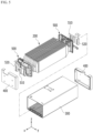
- Fig. 1 is a perspective view showing a conventional battery module
- Fig. 2 is a cross-sectional view taken along the cutting line A-A' of Fig. 1
- Fig. 3 is a perspective view showing an end plate included in the battery module of Fig. 1 .
- Fig. 3 shows the surface of the end plate facing the battery cell.
- a conventional battery module 10 can be manufactured by housing a plurality of battery cells 20 in a module frame 30, and then joining an end plate 40 to the module frame 30.
- each battery module 10 can be fixed to a structure such as a pack frame (not shown).
- the conventional battery module 10 may be fixed by forming a mounting structure at four corners. Specifically, mounting holes 40H into which bolts 40B can be inserted can be formed at both ends of the end plate 40 of the battery module 10. The bolt 40B is inserted in the downward direction into the mounting hole 40H, and the nut 40N is coupled to the end of the bolt 40B, so that the battery module 10 can be fixed to the pack frame or the like.
- the mounting hole 40H has a form that extends along a height direction (a direction parallel to the z-axis) as shown in the figure. Therefore, referring to Figs. 2 and 3 , waste of the space occurs as much as the space in which the mounting hole 40H is formed between the end plate 40 and the battery cells 20. That is, in order to fix the battery module 10, mounting holes 40H that extend along the height direction were formed at both ends of the end plate 40, but this caused the deterioration of the space utilization of the battery module 10.
- Increasing the space utilization of the battery module is directly linked to the performance of the battery pack, such as increasing the energy density of the battery module and the battery pack including the same, or enabling downsizing of the battery pack, there is a need to improve the space utilization of the battery module.
- a battery module comprising: a battery cell stack in which a plurality of battery cells are stacked; a module frame that houses the battery cell stack and is opened in its one surface; and end plate that covers the opened one surface of the module frame, wherein the end plate comprises a mounting portion having a mounting hole formed therein, and wherein the mounting hole is opened at a lower surface of the end plate, and a thread is formed on an inside surface of the mounting hole.
- a height of the mounting portion may be 0.5 times or less a height of the end plate, and an empty space may be provided in the upper portion of the mounting portion between the end plate and the battery cell stack.
- the end plate may include a body portion, first and second side portions, an upper side portion and a lower side portion.
- the body portion may face the battery cell stack, and the first and second side portions, the upper side portion, and the lower side portion may be respectively extended in a direction perpendicular to one surface of the body portion from both sides, an upper side, and a lower side of the body portion.
- the mounting hole may be opened at a lower surface of the lower side portion of the end plate, and the mounting portion may be extended along a direction parallel to the one surface of the body portion.
- the module frame may be opened in its other surface facing the one surface, and the end plate is configured by a plurality of numbers and may cover the opened one surface and the opened other surface of the module frame, respectively.
- a battery pack comprising: the battery module; a pack frame that houses the battery module; and a bolt that passes through a through hole formed at the bottom portion of the pack frame and is coupled to the mounting hole.
- the bolt may be coupled upwardly to the mounting hole.
- the bottom portion of the pack frame may include a mounting plate for supporting the battery module and a lower plate located under the mounting plate.
- the through hole is formed in the mounting plate, and the bolt may pass through the through hole of the mounting plate to be coupled to the mounting hole.
- an opening may be formed in a portion corresponding to the through hole.
- the pack frame may further include a side surface portion located on the side surface of the battery module.
- the side surface portion may be in contact with each of the mounting plate and the lower plate, and a sealing member may be located between the side surface portion and the mounting plate.
- a lower through hole may be formed in the lower plate, and the bolt may pass through the lower through hole of the lower plate and the through hole of the mounting plate to be coupled to the mounting hole.
- the pack frame may further include a side surface portion located on the side surface of the battery module, the side surface portion may be in contact with each of the mounting plate and the lower plate, and a sealing member may be located between the side surface portion and the lower plate.
- a mounting hole is provided at the lower side of the battery module, and the height of the mounting part is adjusted, thereby capable of forming a mounting structure and at the same time, providing an additional space therein and increasing space utilization.
- planar when referred to as “planar”, it means when a target portion is viewed from the upper side, and when referred to as “cross-sectional”, it means when a target portion is viewed from the side of a cross section cut vertically.
- Fig. 4 is a perspective view showing a battery module according to an embodiment of the present disclosure.
- Fig. 5 is an exploded perspective view of the battery module of Fig. 4 .
- Fig. 6 is a perspective view of a battery cell included in the battery module of Fig. 5 .
- a battery module 100a includes a battery cell stack 200 in which a plurality of battery cells 110 are stacked, a module frame 300 that houses the battery cell stack 200 and is opened in its one surface, and end plate 400 hat covers the opened one surface of the module frame 300.
- the battery cell 110 is preferably a pouch-type battery cell, and may be formed in a rectangular sheet-like structure.
- the battery cell 110 according to the present embodiment has a structure in which the two electrode leads 111 and 112 face each other and protrude from one end and the other end, respectively.
- the battery cell 110 has a structure in which the two electrode leads 111 and 112 face each other and protrude from one end 114a and the other end 114b, respectively. More specifically, the electrode leads 111 and 112 are connected to an electrode assembly (not shown) and are protruded from the electrode assembly (not shown) to the outside of the battery cell 110.
- the battery cell 110 can be manufactured by joining both ends 114a and 114b of a cell case 114 and one side portion 114c connecting them in a state in which an electrode assembly (not shown) is housed in a cell case 114.
- the battery cells 110 according to the present embodiment have a total of three sealing portions 114sa, 114sb and 114sc, the sealing portions 114sa, 114sb and 114sc have a structure that is sealed by a method such as heat-sealing, and the remaining other one side portion can be composed of a connection part 115.
- the cell case 114 can be composed of a laminated sheet including a resin layer and a metal layer.
- connection portion 115 may extend long along one edge of the battery cell 110, and a protrusion portion 110p of the battery cell 110 called a bat-ear may be formed at an end portion of the connection part 115.
- the protrusion portion 110p is an exemplary structure, and the battery cell 110 according to another embodiment of the present disclosure may have a form in which a protrusion portion is not formed and the connection portion 115 extends in a straight line.
- the battery cell 110 may be configured by a plurality of numbers, and the plurality of battery cells 110 may be stacked so as to be electrically connected to each other, thereby forming a battery cell stack 200. Particularly, as shown in Fig. 5 , the plurality of battery cells 110 can be stacked along the y-axis direction. Thereby, one electrode lead 111 of the battery cells 110 may be protruded toward the x-axis direction, and the other electrode lead 112 may be protruded toward the -x-axis direction.
- the module frame 300 may be opened not only at the one surface but also at the other surface facing the one surface. More specifically, the module frame 300 may be opened in both directions in which the electrode leads 111 and 112 protrude with respect to the battery cell stack 200.
- the end plate 400 may be configured by a plurality of numbers and can cover the opened one surface and the opened other surface of the module frame 300, respectively.
- the battery cell stack 200 is housed in the module frame 300 and the end plate 400, thereby capable of physically protecting the battery cell stack 200.
- the module frame 300 and the end plate 400 may include a metal material having a predetermined strength. Meanwhile, the module frame 300 and the end plate 400 may be joined by a method such as welding in a state in which corresponding corner portions are in contact with each other.
- the battery module 100 may further include a busbar frame 500 on which a busbar 510 and a terminal busbar 520 are mounted.
- the busbar 510 and the terminal busbar 520 can be joined to the electrode leads 111 and 112 of the battery cells 110 in order to electrically connect the plurality of battery cells 110.
- the busbar frame 500 on which the busbar 510 and the terminal busbar 520 are mounted can be disposed on the one surface (x-axis direction) and the other surface (-x-axis direction) of the battery cell stack 200.
- the one surface (x-axis direction) and the other surface (-x-axis direction) of the battery cell stack 200 correspond to the surfaces in the direction in which the electrode leads 111 and 112 of the battery cells 110 protrude.
- the busbar frame 500 may be located between the battery cell stack 200 and the end plate 400.
- a lead slit may be formed at the busbar frame 500, and the electrode leads 111 and 112 can be bent after passing through the lead slit, and joined to the busbar 510 or the terminal busbar 520.
- the joining method is not particularly limited, and weld-joining can be performed as an example.
- a slit may be formed in the busbar 510 or the terminal busbar 520, and the slit may be located so as to correspond to the lead slit of the busbar frame 500.
- the electrode leads 111 and 112 that have passed through the lead slit may be bent by passing through the slit of the busbar 510 or the slit of the terminal bus bar 520.
- a part of the terminal busbar 520 may be exposed to the outside of the battery module 100. Specifically, an opening is formed in the end plate 400 or an insulating cover (not shown), and a part of the terminal busbar 520 may be exposed as shown in Fig. 4 .
- a part of the exposed terminal busbar 520 can be connected to another battery module or a BDU (battery disconnect unit) or the like to realize a high voltage (HV) connection.
- the HV connection is a connection that plays a role of a power source for supplying electric power, and refers to a connection between battery cells or a connection between battery modules.
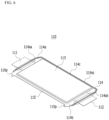
- Fig. 7 is a partial perspective view showing a state in which the lower surface of the battery module of Fig. 4 is inverted so as to face upward.
- Fig. 8 is a perspective view of an end plate included in the battery module of Fig. 5 . Particularly, Fig. 8 shows a surface of the end plate facing the battery cell stack.
- the end plate 400 includes a mounting portion 400M in which a mounting hole 400H is formed.
- the mounting hole 400H is opened at the lower surface of the end plate 400, and a thread is formed on the inner surface of the mounting hole 400H.
- the end plate 400 may include a body portion 450, first and second side portions 410 and 420, an upper side portion 430, and a lower side portion 440.
- the body portion 450 is a portion facing the battery cell stack 200
- the first and second side portions 410 and 420, the upper side portion 430, and the lower side portion 440 are portions that are extended in a direction perpendicular to one surface of the body portion 450 from both sides, an upper side, and a lower side of the body portion 450. That is, the end plate 400 according to the present embodiment may have a cover shape that is opened in one surface facing the battery cell stack 200.
- the mounting hole 400H may be opened on the lower surface of the lower portion 440 of the end plate 400, and the mounting portion 400M may extend along a direction parallel to one surface of the body portion 450. Thereby, in the mounting structure for fixing the battery module 100 to the pack frame, etc., the bolt inserted into the mounting hole 400H may be coupled upwardly to the mounting hole 400H.
- the height h2 of the mounting portion 400M in which the mounting hole is formed may be 0.5 times or less the height h1 of the end plate 400.
- the height h2 of the mounting portion 400M may be 0.3 times or less, more preferably 0.2 times or less the height h1 of the end plate 400. That is, since the mounting hole 400H according to the present embodiment is opened on the lower surface of the lower portion 440 of the end plate 400, the height of the mounting part 400M does not need to be formed in the same manner as the height of the end plate 400, unlike the conventional end plate 40 shown in Fig. 3 .
- the battery module 100 can be sufficiently fixed. Therefore, an empty space can be provided in the upper portion of the mounting portion 400M between the end plate 400 and the battery cell stack 200.
- the lower limit of the height is not particularly limited, but the height h2 of the mounting portion 400M may be 0.05 times or more the height h1 of the end plate 400 in order to have the minimum degree of fastening.
- the conventional battery module 10 has a mounting hole 40H structure that is long in the height direction, and needs to secure a space for mounting and fastening, whereas the battery module 100 according to the present embodiment can implement a mounting hole 400H structure that is short in the height direction, and thus can secure an additional space within the battery module 100. It is possible to utilize the space, such as configuring the conventional wasted space to increase the battery capacity. Because of this advantage in terms of space utilization, the battery module and the battery pack including the same according to the present embodiment can have advantages in terms of energy density or downsizing.
- Fig. 9 is a partial perspective view of a battery module and a pack frame according to an embodiment of the present disclosure.
- Fig. 10 is a schematic diagram showing a state in which a battery module according to an embodiment of the present disclosure is mounted on a pack frame.
- the battery pack 1000 includes a battery module 100, a pack frame 1100 that houses the battery module 100, and a bolt 1200 that passes through the through hole 1111H formed in the bottom portion 1110 of the pack frame 1100 to be coupled to the mounting hole 400H.
- the battery modules 100 may be gathered by a plurality of numbers to form a battery pack 1000, wherein each battery module 100 may be fixed to a structure such as the pack frame 1100. At this time, a through hole 1111H is formed in the bottom portion 1110 of the pack frame 1100, and the bolt 1200 passes upwardly through the through hole 1111H, and then can be fastened to the mounting hole 400H of the battery module 100.
- the bottom portion 1110 of the pack frame 1100 may include a mounting plate 1111 for supporting the battery module 100, and a lower plate 1112 located under mounting plate 1111.
- the mounting plate 1111 By forming the above-mentioned through hole 1111H in the mounting plate 1111, it is possible to support the battery module 100 and at the same time, fix the battery module 100 to the mounting plate 1111, thereby forming a mounting structure. That is, the mounting hole 400H of the battery module 100 and the bolt 1200 may be coupled with the mounting plate 1111 being interposed therebetween.
- the lower plate 1112 is located under the mounting plate 1111, and although not specifically shown in the figure, an equipment such as a cooling water supply pipe for supplying cooling the battery module 100 may be provided between the mounting plate 1111 and the lower plate 1112.
- an equipment such as a cooling water supply pipe for supplying cooling the battery module 100 may be provided between the mounting plate 1111 and the lower plate 1112.
- an opening 1112P may be formed in a portion corresponding to the through hole 1111H formed in the mounting plate 1111. That is, an opening 1112P having an opening shape may be formed in each of the portions corresponding to the through hole 1111H with reference to the Z-axis direction.
- the bolt 1200 according to the present embodiment is coupled upwardly to the mounting hole 400H of the battery module 100, but a space is needed for mounting the equipment for assembling the bolt 1200. Therefore, by forming the opening 1112P in the lower plate 1112, a space for assembling the bolt 1200 is provided.
- the pack frame 1100 may further include a side surface portion 1120 located on side surface of the battery module 100 and bottom portion 1110.
- the side surface portion 1120 can form a stepped structure and come into contact with each of the mounting plate 1111 and the lower plate 1112.
- a sealing member 1300 having adhesive properties may be located between the side surface portion 1120 and the mounting plate 1111. That is, the side surface portion 1120 and the mounting plate 1111 are adhered and fixed, and at the same time, a gap therebetween can be sealed by the sealing member 1300.
- the sealing member 1300 according to the present embodiment is located between the side surface portion 1120 and the mounting plate 1111, the space between the side surface portion 1120 and the mounting plate 1111 is sealed even if the opening 1112P is formed, whereby it is possible to prevent water or the like from flowing into the pack frame 1100.
- the material of the sealing member 1300 is not particularly limited. As described above, a space for assembling the bolt 1200 must be secured, such as an opening 1112P being formed in the lower plate 1112, and it is necessary to seal between the mounting plate 1111 and the side surface portion 1120 to prevent the inflow of water. Thus, it is preferable that the sealing member 1300 is located between the side surface portion 1120 and the mounting plate 1111 to be adhered and sealed.
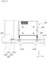
- Fig. 11 is a schematic diagram showing a state in which a battery module according to a modified embodiment of the present disclosure is mounted on a pack frame. Parts overlapping with the above-mentioned contents are omitted in order to avoid repetition of the description.
- the bottom portion 1110 of the pack frame 1100 may include a mounting plate 1111 for supporting the battery module 100 and a lower plate 1112' located under mounting plate 1111.
- the pack frame 1100 may further include a side surface portion 1120 located on the side surface of the battery module 100.
- the lower plate 1112' according to the present embodiment can be formed with a lower through hole 1112H rather than an opening, and the lower through hole 1112H of the lower plate 1112' may be located so as to correspond to the through hole 1111H of the mounting plate 1111 with reference to the Z-axis direction.
- the bolt 1200' according to the present embodiment is formed longer than the bolt 1200 described in Fig. 10 , and after sequentially passing through the lower through hole 1112H of the lower plate 1112' and the through hole 1111H of the mounting plate 1111, it can be coupled to the mounting hole 400H of the battery module 100.
- the adhesive sealing member 1300' according to the present embodiment may be located between the side surface portion 1120 and the lower plate 1112'. Since the lower through hole 1112H of the lower plate 1112' is naturally sealed by the insertion of the bolt 1200' according to the present embodiment, a sealing member 1300' for preventing water from entering the pack frame 1100 can be located between the side surface portion 1120 and the lower plate 1112'. That is, the sealing member 1300' according to the present embodiment can play a function of preventing water inflow while being located between the side surface portion 1120 and the lower plate 1112'. Meanwhile, if necessary, a ring-shaped stopper for sealing may be disposed between the head of the bolt 1200' and the lower plate 1112' according to the present embodiment.
- the one or more battery modules according to embodiments of the present disclosure described above can be mounted together with various control and protection systems such as a battery management system (BMS) and a cooling system to form a battery pack.
- BMS battery management system
- a cooling system to form a battery pack.
- the battery module or the battery pack can be applied to various devices.
- vehicle means such as an electric bike, an electric vehicle, and a hybrid electric vehicle, and may be applied to various devices capable of using a secondary battery, without being limited thereto.
Landscapes
- Chemical & Material Sciences (AREA)
- Chemical Kinetics & Catalysis (AREA)
- Electrochemistry (AREA)
- General Chemical & Material Sciences (AREA)
- Inorganic Chemistry (AREA)
- Battery Mounting, Suspending (AREA)
Abstract
Description
- This application claims the benefit of
Korean Patent Application No. 10-2020-0153468 filed on November 17, 2020 - The present disclosure relates to a battery module and a battery pack including the same, and more particularly to a battery module having improved space utilization and a battery pack including the same.
- In modern society, as portable devices such as a mobile phone, a notebook computer, a camcorder and a digital camera has been daily used, the development of technologies in the fields related to mobile devices as described above has been activated. In addition, chargeable/dischargeable secondary batteries are used as a power source for an electric vehicle (EV), a hybrid electric vehicle (HEV), a plug-in hybrid electric vehicle (P-HEV) and the like, in an attempt to solve air pollution and the like caused by existing gasoline vehicles using fossil fuel. Therefore, there is a growing need for development of the secondary battery.
- Currently commercialized secondary batteries include a nickel cadmium battery, a nickel hydrogen battery, a nickel zinc battery, a lithium secondary battery, and the like. Among them, the lithium secondary battery has come into the spotlight because they have advantages, for example, hardly exhibiting memory effects compared to nickel-based secondary batteries and thus being freely charged and discharged, and having very low self-discharge rate and high energy density.
- Such lithium secondary battery mainly uses a lithium-based oxide and a carbonaceous material as a cathode active material and an anode active material, respectively. The lithium secondary battery includes an electrode assembly in which a cathode plate and an anode plate each coated with the cathode active material and the anode active material are disposed with a separator being interposed between them, and a battery case that seals and houses the electrode assembly together with an electrolyte solution.
- Generally, the lithium secondary battery may be classified based on the shape of the exterior material into a can type secondary battery in which the electrode assembly is built in a metal can, and a pouch type secondary battery in which the electrode assembly is built in a pouch made of an aluminum laminate sheet.
- In the case of a secondary battery used for small-sized devices, two to three battery cells are disposed, but in the case of a secondary battery used for a middle or large-sized device such as an automobile, a battery module in which a large number of battery cells are electrically connected is used. In such a battery module, a large number of battery cells are connected to each other in series or in parallel to form a cell stack, thereby improving capacity and output. In addition, one or more battery modules may be mounted together with various control and protection systems such as BMS (battery management system) and a cooling system to form a battery pack.
-
Fig. 1 is a perspective view showing a conventional battery module,Fig. 2 is a cross-sectional view taken along the cutting line A-A' ofFig. 1 , andFig. 3 is a perspective view showing an end plate included in the battery module ofFig. 1 . Particularly,Fig. 3 shows the surface of the end plate facing the battery cell. - Referring to
Figs. 1 to 3 , a conventional battery module 10 can be manufactured by housing a plurality ofbattery cells 20 in amodule frame 30, and then joining anend plate 40 to themodule frame 30. When the battery modules 10 are gathered by a plurality of numbers to form a battery pack, or when the battery modules are mounted on a vehicle or the like, each battery module 10 can be fixed to a structure such as a pack frame (not shown). At this time, the conventional battery module 10 may be fixed by forming a mounting structure at four corners. Specifically, mountingholes 40H into whichbolts 40B can be inserted can be formed at both ends of theend plate 40 of the battery module 10. Thebolt 40B is inserted in the downward direction into themounting hole 40H, and thenut 40N is coupled to the end of thebolt 40B, so that the battery module 10 can be fixed to the pack frame or the like. - However, in the case of the conventional battery module 10, since the
bolt 40B has a form of being inserted downward, themounting hole 40H has a form that extends along a height direction (a direction parallel to the z-axis) as shown in the figure. Therefore, referring toFigs. 2 and3 , waste of the space occurs as much as the space in which themounting hole 40H is formed between theend plate 40 and thebattery cells 20. That is, in order to fix the battery module 10, mountingholes 40H that extend along the height direction were formed at both ends of theend plate 40, but this caused the deterioration of the space utilization of the battery module 10. - Increasing the space utilization of the battery module is directly linked to the performance of the battery pack, such as increasing the energy density of the battery module and the battery pack including the same, or enabling downsizing of the battery pack, there is a need to improve the space utilization of the battery module.
- It is an object of the present disclosure to provide a battery module capable of providing additional space inside while forming a mounting structure, and a battery pack including the same.
- However, the problem to be solved by embodiments of the present disclosure is not limited to the above-described problems, and can be variously expanded within the scope of the technical idea included in the present disclosure.
- According to one aspect of the present disclosure, there is provided a battery module comprising: a battery cell stack in which a plurality of battery cells are stacked; a module frame that houses the battery cell stack and is opened in its one surface; and end plate that covers the opened one surface of the module frame, wherein the end plate comprises a mounting portion having a mounting hole formed therein, and wherein the mounting hole is opened at a lower surface of the end plate, and a thread is formed on an inside surface of the mounting hole.
- A height of the mounting portion may be 0.5 times or less a height of the end plate, and an empty space may be provided in the upper portion of the mounting portion between the end plate and the battery cell stack.
- The end plate may include a body portion, first and second side portions, an upper side portion and a lower side portion. The body portion may face the battery cell stack, and the first and second side portions, the upper side portion, and the lower side portion may be respectively extended in a direction perpendicular to one surface of the body portion from both sides, an upper side, and a lower side of the body portion.
- The mounting hole may be opened at a lower surface of the lower side portion of the end plate, and the mounting portion may be extended along a direction parallel to the one surface of the body portion.
- The module frame may be opened in its other surface facing the one surface, and the end plate is configured by a plurality of numbers and may cover the opened one surface and the opened other surface of the module frame, respectively.
- According to another aspect of the present disclosure, there is provided a battery pack comprising: the battery module; a pack frame that houses the battery module; and a bolt that passes through a through hole formed at the bottom portion of the pack frame and is coupled to the mounting hole.
- The bolt may be coupled upwardly to the mounting hole.
- The bottom portion of the pack frame may include a mounting plate for supporting the battery module and a lower plate located under the mounting plate. The through hole is formed in the mounting plate, and the bolt may pass through the through hole of the mounting plate to be coupled to the mounting hole.
- In the lower plate, an opening may be formed in a portion corresponding to the through hole.
- The pack frame may further include a side surface portion located on the side surface of the battery module. The side surface portion may be in contact with each of the mounting plate and the lower plate, and a sealing member may be located between the side surface portion and the mounting plate.
- A lower through hole may be formed in the lower plate, and the bolt may pass through the lower through hole of the lower plate and the through hole of the mounting plate to be coupled to the mounting hole.
- The pack frame may further include a side surface portion located on the side surface of the battery module, the side surface portion may be in contact with each of the mounting plate and the lower plate, and a sealing member may be located between the side surface portion and the lower plate.
- According to embodiments of the present disclosure, a mounting hole is provided at the lower side of the battery module, and the height of the mounting part is adjusted, thereby capable of forming a mounting structure and at the same time, providing an additional space therein and increasing space utilization.
- The effects of the present disclosure are not limited to the effects mentioned above and additional other effects not described above will be clearly understood from the description of the appended claims by those skilled in the art.
-
-
Fig. 1 is a perspective view showing a conventional battery module; -
Fig. 2 is a cross-sectional view taken along the cutting line A-A' ofFig. 1 ; -
Fig. 3 is a perspective view showing an end plate included in the battery module ofFig. 1 ; -
Fig. 4 is a perspective view showing a battery module according to an embodiment of the present disclosure; -
Fig. 5 is an exploded perspective view of the battery module ofFig. 4 ; -
Fig. 6 is a perspective view of a battery cell included in the battery module ofFig. 5 ; -
Fig. 7 is a partial perspective view showing a state in which the lower surface of the battery module ofFig. 4 is inverted so as to face upward. -
Fig. 8 is a perspective view of an end plate included in the battery module ofFig. 5 ; -
Fig. 9 is a partial perspective view of a battery module and a pack frame according to an embodiment of the present disclosure; -
Fig. 10 is a schematic diagram showing a state in which a battery module according to an embodiment of the present disclosure is mounted on a pack frame; and -
Fig. 11 is a schematic diagram showing a state in which a battery module according to a modified embodiment of the present disclosure is mounted on a pack frame. - Hereinafter, various embodiments of the present disclosure will be described in detail with reference to the accompanying drawings so that those skilled in the art can easily carry out them. The present disclosure may be modified in various different ways, and is not limited to the embodiments set forth herein.
- A description of parts not related to the description will be omitted herein for clarity, and like reference numerals designate like elements throughout the description.
- Further, in the drawings, the size and thickness of each element are arbitrarily illustrated for convenience of description, and the present disclosure is not necessarily limited to those illustrated in the drawings. In the drawings, the thickness of layers, regions, etc. are exaggerated for clarity. In the drawings, for convenience of description, the thicknesses of some layers and regions are exaggerated.
- In addition, it will be understood that when an element such as a layer, film, region, or plate is referred to as being "on" or "above" another element, it can be directly on the other element or intervening elements may also be present. In contrast, when an element is referred to as being "directly on" another element, it means that other intervening elements are not present. Further, the word "on" or "above" means disposed on or below a reference portion, and does not necessarily mean being disposed on the upper end of the reference portion toward the opposite direction of gravity.
- Further, throughout the description, when a portion is referred to as "including" a certain component, it means that the portion can further include other components, without excluding the other components, unless otherwise stated.
- Further, throughout the description, when referred to as "planar", it means when a target portion is viewed from the upper side, and when referred to as "cross-sectional", it means when a target portion is viewed from the side of a cross section cut vertically.
-
Fig. 4 is a perspective view showing a battery module according to an embodiment of the present disclosure.Fig. 5 is an exploded perspective view of the battery module ofFig. 4 .Fig. 6 is a perspective view of a battery cell included in the battery module ofFig. 5 . - Referring to
Figs. 4 to 6 , a battery module 100a according to one embodiment of the present disclosure includes abattery cell stack 200 in which a plurality ofbattery cells 110 are stacked, amodule frame 300 that houses thebattery cell stack 200 and is opened in its one surface, andend plate 400 hat covers the opened one surface of themodule frame 300. - First, the
battery cell 110 is preferably a pouch-type battery cell, and may be formed in a rectangular sheet-like structure. For example, thebattery cell 110 according to the present embodiment has a structure in which the two electrode leads 111 and 112 face each other and protrude from one end and the other end, respectively. - Particularly, referring to
Fig.6 , thebattery cell 110 according to the present embodiment has a structure in which the two electrode leads 111 and 112 face each other and protrude from oneend 114a and theother end 114b, respectively. More specifically, the electrode leads 111 and 112 are connected to an electrode assembly (not shown) and are protruded from the electrode assembly (not shown) to the outside of thebattery cell 110. - Meanwhile, the
battery cell 110 can be manufactured by joining bothends cell case 114 and oneside portion 114c connecting them in a state in which an electrode assembly (not shown) is housed in acell case 114. In other words, thebattery cells 110 according to the present embodiment have a total of three sealing portions 114sa, 114sb and 114sc, the sealing portions 114sa, 114sb and 114sc have a structure that is sealed by a method such as heat-sealing, and the remaining other one side portion can be composed of aconnection part 115. Thecell case 114 can be composed of a laminated sheet including a resin layer and a metal layer. - Further, the
connection portion 115 may extend long along one edge of thebattery cell 110, and aprotrusion portion 110p of thebattery cell 110 called a bat-ear may be formed at an end portion of theconnection part 115. However, theprotrusion portion 110p is an exemplary structure, and thebattery cell 110 according to another embodiment of the present disclosure may have a form in which a protrusion portion is not formed and theconnection portion 115 extends in a straight line. - The
battery cell 110 may be configured by a plurality of numbers, and the plurality ofbattery cells 110 may be stacked so as to be electrically connected to each other, thereby forming abattery cell stack 200. Particularly, as shown inFig. 5 , the plurality ofbattery cells 110 can be stacked along the y-axis direction. Thereby, oneelectrode lead 111 of thebattery cells 110 may be protruded toward the x-axis direction, and theother electrode lead 112 may be protruded toward the -x-axis direction. - The
module frame 300 may be opened not only at the one surface but also at the other surface facing the one surface. More specifically, themodule frame 300 may be opened in both directions in which the electrode leads 111 and 112 protrude with respect to thebattery cell stack 200. Theend plate 400 may be configured by a plurality of numbers and can cover the opened one surface and the opened other surface of themodule frame 300, respectively. Thebattery cell stack 200 is housed in themodule frame 300 and theend plate 400, thereby capable of physically protecting thebattery cell stack 200. For this purpose, themodule frame 300 and theend plate 400 may include a metal material having a predetermined strength. Meanwhile, themodule frame 300 and theend plate 400 may be joined by a method such as welding in a state in which corresponding corner portions are in contact with each other. - Meanwhile, the
battery module 100 according to the present embodiment may further include abusbar frame 500 on which abusbar 510 and aterminal busbar 520 are mounted. - The
busbar 510 and theterminal busbar 520 can be joined to the electrode leads 111 and 112 of thebattery cells 110 in order to electrically connect the plurality ofbattery cells 110. Specifically, thebusbar frame 500 on which thebusbar 510 and theterminal busbar 520 are mounted can be disposed on the one surface (x-axis direction) and the other surface (-x-axis direction) of thebattery cell stack 200. The one surface (x-axis direction) and the other surface (-x-axis direction) of thebattery cell stack 200 correspond to the surfaces in the direction in which the electrode leads 111 and 112 of thebattery cells 110 protrude. In other words, thebusbar frame 500 may be located between thebattery cell stack 200 and theend plate 400. - A lead slit may be formed at the
busbar frame 500, and the electrode leads 111 and 112 can be bent after passing through the lead slit, and joined to thebusbar 510 or theterminal busbar 520. As long as physical and electrical connection is possible, the joining method is not particularly limited, and weld-joining can be performed as an example. - Meanwhile, a slit may be formed in the
busbar 510 or theterminal busbar 520, and the slit may be located so as to correspond to the lead slit of thebusbar frame 500. The electrode leads 111 and 112 that have passed through the lead slit may be bent by passing through the slit of thebusbar 510 or the slit of theterminal bus bar 520. - Meanwhile, a part of the
terminal busbar 520 may be exposed to the outside of thebattery module 100. Specifically, an opening is formed in theend plate 400 or an insulating cover (not shown), and a part of theterminal busbar 520 may be exposed as shown inFig. 4 . A part of the exposedterminal busbar 520 can be connected to another battery module or a BDU (battery disconnect unit) or the like to realize a high voltage (HV) connection. Here, the HV connection is a connection that plays a role of a power source for supplying electric power, and refers to a connection between battery cells or a connection between battery modules. - Next, an end plate, a mounting portion, and a mounting hole according to an embodiment of the present disclosure will be described in detail with reference to
Figs. 7 and8 . -
Fig. 7 is a partial perspective view showing a state in which the lower surface of the battery module ofFig. 4 is inverted so as to face upward.Fig. 8 is a perspective view of an end plate included in the battery module ofFig. 5 . Particularly,Fig. 8 shows a surface of the end plate facing the battery cell stack. - Referring to
Figs. 5 ,7 and8 , theend plate 400 according to the present embodiment includes a mountingportion 400M in which a mountinghole 400H is formed. The mountinghole 400H is opened at the lower surface of theend plate 400, and a thread is formed on the inner surface of the mountinghole 400H. - More specifically, the
end plate 400 according to the present embodiment may include abody portion 450, first andsecond side portions upper side portion 430, and alower side portion 440. Thebody portion 450 is a portion facing thebattery cell stack 200, and the first andsecond side portions upper side portion 430, and thelower side portion 440 are portions that are extended in a direction perpendicular to one surface of thebody portion 450 from both sides, an upper side, and a lower side of thebody portion 450. That is, theend plate 400 according to the present embodiment may have a cover shape that is opened in one surface facing thebattery cell stack 200. - At this time, the mounting
hole 400H according to the present embodiment may be opened on the lower surface of thelower portion 440 of theend plate 400, and the mountingportion 400M may extend along a direction parallel to one surface of thebody portion 450. Thereby, in the mounting structure for fixing thebattery module 100 to the pack frame, etc., the bolt inserted into the mountinghole 400H may be coupled upwardly to the mountinghole 400H. - Meanwhile, referring to
Fig. 8 , the height h2 of the mountingportion 400M in which the mounting hole is formed may be 0.5 times or less the height h1 of theend plate 400. In another example, the height h2 of the mountingportion 400M may be 0.3 times or less, more preferably 0.2 times or less the height h1 of theend plate 400. That is, since the mountinghole 400H according to the present embodiment is opened on the lower surface of thelower portion 440 of theend plate 400, the height of the mountingpart 400M does not need to be formed in the same manner as the height of theend plate 400, unlike theconventional end plate 40 shown inFig. 3 . Even if the height h2 of the mountingportion 400M is formed to be low by 0.5 times or less the height h1 of theend plate 400, thebattery module 100 can be sufficiently fixed. Therefore, an empty space can be provided in the upper portion of the mountingportion 400M between theend plate 400 and thebattery cell stack 200. The lower limit of the height is not particularly limited, but the height h2 of the mountingportion 400M may be 0.05 times or more the height h1 of theend plate 400 in order to have the minimum degree of fastening. The conventional battery module 10 has a mountinghole 40H structure that is long in the height direction, and needs to secure a space for mounting and fastening, whereas thebattery module 100 according to the present embodiment can implement a mountinghole 400H structure that is short in the height direction, and thus can secure an additional space within thebattery module 100. It is possible to utilize the space, such as configuring the conventional wasted space to increase the battery capacity. Because of this advantage in terms of space utilization, the battery module and the battery pack including the same according to the present embodiment can have advantages in terms of energy density or downsizing. - Next, a battery pack according to an embodiment of the present disclosure will be described in detail with reference to
Figs. 9 and10 . -
Fig. 9 is a partial perspective view of a battery module and a pack frame according to an embodiment of the present disclosure.Fig. 10 is a schematic diagram showing a state in which a battery module according to an embodiment of the present disclosure is mounted on a pack frame. - Referring to
Figs, 7 ,9 and10 , thebattery pack 1000 according to an embodiment of the present disclosure includes abattery module 100, apack frame 1100 that houses thebattery module 100, and abolt 1200 that passes through the throughhole 1111H formed in thebottom portion 1110 of thepack frame 1100 to be coupled to the mountinghole 400H. - The
battery modules 100 may be gathered by a plurality of numbers to form abattery pack 1000, wherein eachbattery module 100 may be fixed to a structure such as thepack frame 1100. At this time, a throughhole 1111H is formed in thebottom portion 1110 of thepack frame 1100, and thebolt 1200 passes upwardly through the throughhole 1111H, and then can be fastened to the mountinghole 400H of thebattery module 100. - More specifically, the
bottom portion 1110 of thepack frame 1100 according to the present embodiment may include a mountingplate 1111 for supporting thebattery module 100, and alower plate 1112 located under mountingplate 1111. - By forming the above-mentioned through
hole 1111H in the mountingplate 1111, it is possible to support thebattery module 100 and at the same time, fix thebattery module 100 to the mountingplate 1111, thereby forming a mounting structure. That is, the mountinghole 400H of thebattery module 100 and thebolt 1200 may be coupled with the mountingplate 1111 being interposed therebetween. - Meanwhile, the
lower plate 1112 is located under the mountingplate 1111, and although not specifically shown in the figure, an equipment such as a cooling water supply pipe for supplying cooling thebattery module 100 may be provided between the mountingplate 1111 and thelower plate 1112. - Meanwhile, referring to
Fig. 10 , in thelower plate 1112 according to the present embodiment, anopening 1112P may be formed in a portion corresponding to the throughhole 1111H formed in the mountingplate 1111. That is, anopening 1112P having an opening shape may be formed in each of the portions corresponding to the throughhole 1111H with reference to the Z-axis direction. As described above, thebolt 1200 according to the present embodiment is coupled upwardly to the mountinghole 400H of thebattery module 100, but a space is needed for mounting the equipment for assembling thebolt 1200. Therefore, by forming theopening 1112P in thelower plate 1112, a space for assembling thebolt 1200 is provided. - Meanwhile, the
pack frame 1100 may further include aside surface portion 1120 located on side surface of thebattery module 100 andbottom portion 1110. Theside surface portion 1120 can form a stepped structure and come into contact with each of the mountingplate 1111 and thelower plate 1112. At this time, a sealingmember 1300 having adhesive properties may be located between theside surface portion 1120 and the mountingplate 1111. That is, theside surface portion 1120 and the mountingplate 1111 are adhered and fixed, and at the same time, a gap therebetween can be sealed by the sealingmember 1300. As the sealingmember 1300 according to the present embodiment is located between theside surface portion 1120 and the mountingplate 1111, the space between theside surface portion 1120 and the mountingplate 1111 is sealed even if theopening 1112P is formed, whereby it is possible to prevent water or the like from flowing into thepack frame 1100. - Meanwhile, if the
side surface portion 1120 and the mountingplate 1111 have adhesive properties so that they can be adhered, fixed, and sealed, the material of the sealingmember 1300 is not particularly limited. As described above, a space for assembling thebolt 1200 must be secured, such as anopening 1112P being formed in thelower plate 1112, and it is necessary to seal between the mountingplate 1111 and theside surface portion 1120 to prevent the inflow of water. Thus, it is preferable that the sealingmember 1300 is located between theside surface portion 1120 and the mountingplate 1111 to be adhered and sealed. -
Fig. 11 is a schematic diagram showing a state in which a battery module according to a modified embodiment of the present disclosure is mounted on a pack frame. Parts overlapping with the above-mentioned contents are omitted in order to avoid repetition of the description. - Referring to
Fig. 11 , thebottom portion 1110 of thepack frame 1100 according to the modified embodiment of the present disclosure may include a mountingplate 1111 for supporting thebattery module 100 and a lower plate 1112' located under mountingplate 1111. Thepack frame 1100 may further include aside surface portion 1120 located on the side surface of thebattery module 100. - At this time, the lower plate 1112' according to the present embodiment can be formed with a lower through
hole 1112H rather than an opening, and the lower throughhole 1112H of the lower plate 1112' may be located so as to correspond to the throughhole 1111H of the mountingplate 1111 with reference to the Z-axis direction. Further, the bolt 1200' according to the present embodiment is formed longer than thebolt 1200 described inFig. 10 , and after sequentially passing through the lower throughhole 1112H of the lower plate 1112' and the throughhole 1111H of the mountingplate 1111, it can be coupled to the mountinghole 400H of thebattery module 100. - At this time, the adhesive sealing member 1300' according to the present embodiment may be located between the
side surface portion 1120 and the lower plate 1112'. Since the lower throughhole 1112H of the lower plate 1112' is naturally sealed by the insertion of the bolt 1200' according to the present embodiment, a sealing member 1300' for preventing water from entering thepack frame 1100 can be located between theside surface portion 1120 and the lower plate 1112'. That is, the sealing member 1300' according to the present embodiment can play a function of preventing water inflow while being located between theside surface portion 1120 and the lower plate 1112'. Meanwhile, if necessary, a ring-shaped stopper for sealing may be disposed between the head of the bolt 1200' and the lower plate 1112' according to the present embodiment. - The terms representing directions such as the front side, the rear side, the left side, the right side, the upper side, and the lower side have been used in embodiments of the present disclosure, but the terms used are provided simply for convenience of description and may become different according to the position of an object, the position of an observer, or the like.
- The one or more battery modules according to embodiments of the present disclosure described above can be mounted together with various control and protection systems such as a battery management system (BMS) and a cooling system to form a battery pack.
- The battery module or the battery pack can be applied to various devices. For example, it can be applied to vehicle means such as an electric bike, an electric vehicle, and a hybrid electric vehicle, and may be applied to various devices capable of using a secondary battery, without being limited thereto.
- Although the invention has been shown and described above with reference to the preferred embodiments, the scope of the present disclosure is not limited thereto, and numerous other modifications and improvements can be devised by those skilled in the art using the basic principles of the invention described in the appended claims, which also falls under the spirit and scope of the present disclosure.
-
- 100: battery module
- 200: battery cell stack
- 300: module frame
- 400: end plate
- 400M: mounting portion
- 400H: mounting hole
Claims (12)
- A battery module comprising:a battery cell stack in which a plurality of battery cells are stacked;a module frame that houses the battery cell stack and is opened in its one surface; andend plate that covers the opened one surface of the module frame,wherein the end plate comprises a mounting portion having a mounting hole formed therein, andwherein the mounting hole is opened at a lower surface of the end plate, and a thread is formed on an inside surface of the mounting hole.
- The battery module according to claim 1, wherein:a height of the mounting portion is 0.5 times or less a height of the end plate, andan empty space is provided in the upper portion of the mounting portion between the end plate and the battery cell stack.
- The battery module according to claim 1, wherein:the end plate comprises a body portion, first and second side portions, an upper side portion and a lower side portion,the body portion faces the battery cell stack, andthe first and second side portions, the upper side portion, and the lower side portion are respectively extended in a direction perpendicular to one surface of the body portion from both sides, an upper side, and a lower side of the body portion.
- The battery module according to claim 3, wherein:the mounting hole is opened at a lower surface of the lower side portion of the end plate,
andthe mounting portion is extended along a direction parallel to the one surface of the body portion. - The battery module according to claim 1, wherein:the module frame is opened in its other surface facing the one surface, andthe end plate is configured by a plurality of numbers and covers the opened one surface and the opened other surface of the module frame, respectively.
- A battery pack comprising:the battery module according to claim 1;a pack frame that houses the battery module; anda bolt that passes through a through hole formed at the bottom portion of the pack frame and is coupled to the mounting hole.
- The battery pack according to claim 6, wherein:
the bolt is coupled upwardly to the mounting hole. - The battery pack according to claim 6, wherein:the bottom portion of the pack frame comprises a mounting plate for supporting the battery module and a lower plate located under the mounting plate, andthe through hole is formed in the mounting plate, and the bolt passes through the through hole of the mounting plate to be coupled to the mounting hole.
- The battery pack according to claim 8, wherein:
in the lower plate, an opening is formed in a portion corresponding to the through hole. - The battery pack according to claim 8, wherein:the pack frame further comprises a side surface portion located on the side surface of the battery module,the side surface portion is in contact with each of the mounting plate and the lower plate, anda sealing member is located between the side surface portion and the mounting plate.
- The battery pack according to claim 8, wherein:a lower through hole is formed in the lower plate, andthe bolt passes through the lower through hole of the lower plate and the through hole of the mounting plate to be coupled to the mounting hole.
- The battery pack according to claim 8, wherein:the pack frame further comprises a side surface portion located on the side surface of the battery module,the side surface portion is in contact with each of the mounting plate and the lower plate, anda sealing member is located between the side surface portion and the lower plate.
Applications Claiming Priority (2)
| Application Number | Priority Date | Filing Date | Title |
|---|---|---|---|
| KR1020200153468A KR20220067118A (en) | 2020-11-17 | 2020-11-17 | Battery module and battery pack including the same |
| PCT/KR2021/014961 WO2022108145A1 (en) | 2020-11-17 | 2021-10-22 | Battery module and battery pack including same |
Publications (3)
| Publication Number | Publication Date |
|---|---|
| EP4199208A1 true EP4199208A1 (en) | 2023-06-21 |
| EP4199208A4 EP4199208A4 (en) | 2024-02-21 |
| EP4199208B1 EP4199208B1 (en) | 2025-04-16 |
Family
ID=81709189
Family Applications (1)
| Application Number | Title | Priority Date | Filing Date |
|---|---|---|---|
| EP21894917.0A Active EP4199208B1 (en) | 2020-11-17 | 2021-10-22 | Battery pack |
Country Status (8)
| Country | Link |
|---|---|
| US (1) | US20230344061A1 (en) |
| EP (1) | EP4199208B1 (en) |
| JP (1) | JP7590032B2 (en) |
| KR (1) | KR20220067118A (en) |
| CN (1) | CN116195115A (en) |
| ES (1) | ES3026514T3 (en) |
| HU (1) | HUE071290T2 (en) |
| WO (1) | WO2022108145A1 (en) |
Cited By (1)
| Publication number | Priority date | Publication date | Assignee | Title |
|---|---|---|---|---|
| RU234478U1 (en) * | 2024-12-24 | 2025-05-29 | федеральное государственное автономное образовательное учреждение высшего образования "Санкт-Петербургский политехнический университет Петра Великого" (ФГАОУ ВО "СПбПУ") | END PLATE OF THE DISASSEMBLEABLE BATTERY MODULE |
Families Citing this family (7)
| Publication number | Priority date | Publication date | Assignee | Title |
|---|---|---|---|---|
| KR102937927B1 (en) * | 2020-09-22 | 2026-03-10 | 주식회사 엘지에너지솔루션 | Battery module and battery pack including the same |
| KR102945051B1 (en) * | 2020-09-22 | 2026-03-26 | 주식회사 엘지에너지솔루션 | Battery module and battery pack including the same |
| CN218385603U (en) * | 2022-10-10 | 2023-01-24 | 中创新航科技股份有限公司 | Battery pack and battery pack |
| KR20240156025A (en) * | 2023-04-21 | 2024-10-29 | 스탠다드에너지(주) | Battery module and battery comprising the same |
| CN118486976B (en) * | 2024-05-31 | 2026-01-13 | 惠州亿纬锂能股份有限公司 | Battery pack box and battery pack |
| WO2025246027A1 (en) * | 2024-05-31 | 2025-12-04 | 惠州亿纬锂能股份有限公司 | Battery pack case and battery pack |
| KR20260047683A (en) * | 2024-10-02 | 2026-04-09 | 주식회사 엘지에너지솔루션 | Battery module easy to install in pack case, and battery pack including the same |
Family Cites Families (11)
| Publication number | Priority date | Publication date | Assignee | Title |
|---|---|---|---|---|
| US8465866B2 (en) * | 2010-04-21 | 2013-06-18 | Samsung Sdi Co., Ltd. | Battery module including a pressure control unit |
| KR101292984B1 (en) | 2011-08-22 | 2013-08-02 | 로베르트 보쉬 게엠베하 | Battery module |
| KR101511024B1 (en) * | 2012-08-07 | 2015-04-17 | 주식회사 엘지화학 | Battery Module Having Assembling-typed Module Case |
| KR102047481B1 (en) * | 2015-10-30 | 2019-11-21 | 주식회사 엘지화학 | Battery module and battery pack including the same |
| US10516145B2 (en) * | 2016-01-26 | 2019-12-24 | Ford Global Technologies, Llc | Battery pack array retention |
| KR102178762B1 (en) * | 2016-12-23 | 2020-11-13 | 주식회사 엘지화학 | The fixed structure of battery module-pack housing using plastic laser welding |
| KR102162968B1 (en) * | 2017-04-07 | 2020-10-07 | 주식회사 엘지화학 | Battery Pack with extendible battery module |
| JP7027255B2 (en) * | 2018-05-31 | 2022-03-01 | 本田技研工業株式会社 | Battery pack |
| CN208923207U (en) * | 2018-11-01 | 2019-05-31 | 宁德时代新能源科技股份有限公司 | A kind of battery modules end plate and its battery modules |
| US20220006134A1 (en) * | 2018-11-28 | 2022-01-06 | Sanyo Electric Co., Ltd. | Battery module |
| CN209344284U (en) * | 2019-02-26 | 2019-09-03 | 宁德时代新能源科技股份有限公司 | A battery module |
-
2020
- 2020-11-17 KR KR1020200153468A patent/KR20220067118A/en not_active Ceased
-
2021
- 2021-10-22 JP JP2023516230A patent/JP7590032B2/en active Active
- 2021-10-22 HU HUE21894917A patent/HUE071290T2/en unknown
- 2021-10-22 ES ES21894917T patent/ES3026514T3/en active Active
- 2021-10-22 EP EP21894917.0A patent/EP4199208B1/en active Active
- 2021-10-22 WO PCT/KR2021/014961 patent/WO2022108145A1/en not_active Ceased
- 2021-10-22 US US18/026,510 patent/US20230344061A1/en active Pending
- 2021-10-22 CN CN202180063070.XA patent/CN116195115A/en active Pending
Cited By (1)
| Publication number | Priority date | Publication date | Assignee | Title |
|---|---|---|---|---|
| RU234478U1 (en) * | 2024-12-24 | 2025-05-29 | федеральное государственное автономное образовательное учреждение высшего образования "Санкт-Петербургский политехнический университет Петра Великого" (ФГАОУ ВО "СПбПУ") | END PLATE OF THE DISASSEMBLEABLE BATTERY MODULE |
Also Published As
| Publication number | Publication date |
|---|---|
| EP4199208A4 (en) | 2024-02-21 |
| JP2023541159A (en) | 2023-09-28 |
| WO2022108145A1 (en) | 2022-05-27 |
| HUE071290T2 (en) | 2025-08-28 |
| EP4199208B1 (en) | 2025-04-16 |
| CN116195115A (en) | 2023-05-30 |
| ES3026514T3 (en) | 2025-06-11 |
| US20230344061A1 (en) | 2023-10-26 |
| KR20220067118A (en) | 2022-05-24 |
| JP7590032B2 (en) | 2024-11-26 |
Similar Documents
| Publication | Publication Date | Title |
|---|---|---|
| EP4199208B1 (en) | Battery pack | |
| US12407042B2 (en) | Battery module and battery pack including the same | |
| US12327850B2 (en) | Battery module and battery pack including the same | |
| EP4184706B1 (en) | Battery module, battery pack including same, and manufacturing method thereof | |
| US20230395946A1 (en) | Battery module and manufacturing method of the same | |
| EP4195365A1 (en) | Battery module and battery pack including same | |
| KR102646710B1 (en) | Battery pack and device including the same | |
| US20230069153A1 (en) | Battery Module, Battery Pack Including The Same And Manufacturing Method Of The Same | |
| US20240106026A1 (en) | Battery module and battery pack including the same | |
| EP4210154A1 (en) | Battery pack and device comprising same | |
| EP4181275B1 (en) | Battery module and battery pack including same | |
| EP4181292A1 (en) | Battery module and battery pack including same | |
| EP4089813A1 (en) | Battery pack and device comprising same | |
| EP4044341A1 (en) | Battery module and battery pack including same | |
| EP4539227A1 (en) | Battery pack and device including the same | |
| EP4181296B1 (en) | Battery pack and device including the same | |
| EP4181286B1 (en) | BATTERY MODULE AND BATTERY BLOCK INCLUDING IT | |
| KR20230083604A (en) | Cell unit and battery pack including the same | |
| EP4607670A1 (en) | Battery module and battery pack including same | |
| EP4250463B1 (en) | Battery module and battery pack comprising same | |
| EP4607672A1 (en) | Battery module and battery pack including same | |
| EP4531183A1 (en) | Battery module and battery pack including same |
Legal Events
| Date | Code | Title | Description |
|---|---|---|---|
| STAA | Information on the status of an ep patent application or granted ep patent |
Free format text: STATUS: THE INTERNATIONAL PUBLICATION HAS BEEN MADE |
|
| PUAI | Public reference made under article 153(3) epc to a published international application that has entered the european phase |
Free format text: ORIGINAL CODE: 0009012 |
|
| STAA | Information on the status of an ep patent application or granted ep patent |
Free format text: STATUS: REQUEST FOR EXAMINATION WAS MADE |
|
| 17P | Request for examination filed |
Effective date: 20230314 |
|
| AK | Designated contracting states |
Kind code of ref document: A1 Designated state(s): AL AT BE BG CH CY CZ DE DK EE ES FI FR GB GR HR HU IE IS IT LI LT LU LV MC MK MT NL NO PL PT RO RS SE SI SK SM TR |
|
| A4 | Supplementary search report drawn up and despatched |
Effective date: 20240123 |
|
| DAV | Request for validation of the european patent (deleted) | ||
| DAX | Request for extension of the european patent (deleted) | ||
| RIC1 | Information provided on ipc code assigned before grant |
Ipc: H01M 50/244 20210101ALI20240117BHEP Ipc: H01M 50/271 20210101ALI20240117BHEP Ipc: H01M 50/264 20210101ALI20240117BHEP Ipc: H01M 50/262 20210101ALI20240117BHEP Ipc: H01M 50/224 20210101ALI20240117BHEP Ipc: H01M 50/211 20210101ALI20240117BHEP Ipc: H01M 50/209 20210101ALI20240117BHEP Ipc: H01M 50/204 20210101ALI20240117BHEP Ipc: H01M 50/20 20210101AFI20240117BHEP |
|
| GRAP | Despatch of communication of intention to grant a patent |
Free format text: ORIGINAL CODE: EPIDOSNIGR1 |
|
| STAA | Information on the status of an ep patent application or granted ep patent |
Free format text: STATUS: GRANT OF PATENT IS INTENDED |
|
| INTG | Intention to grant announced |
Effective date: 20240919 |
|
| GRAJ | Information related to disapproval of communication of intention to grant by the applicant or resumption of examination proceedings by the epo deleted |
Free format text: ORIGINAL CODE: EPIDOSDIGR1 |
|
| STAA | Information on the status of an ep patent application or granted ep patent |
Free format text: STATUS: REQUEST FOR EXAMINATION WAS MADE |
|
| P01 | Opt-out of the competence of the unified patent court (upc) registered |
Free format text: CASE NUMBER: APP_56692/2024 Effective date: 20241017 |
|
| GRAP | Despatch of communication of intention to grant a patent |
Free format text: ORIGINAL CODE: EPIDOSNIGR1 |
|
| STAA | Information on the status of an ep patent application or granted ep patent |
Free format text: STATUS: GRANT OF PATENT IS INTENDED |
|
| INTC | Intention to grant announced (deleted) | ||
| INTG | Intention to grant announced |
Effective date: 20241129 |
|
| GRAS | Grant fee paid |
Free format text: ORIGINAL CODE: EPIDOSNIGR3 |
|
| GRAA | (expected) grant |
Free format text: ORIGINAL CODE: 0009210 |
|
| STAA | Information on the status of an ep patent application or granted ep patent |
Free format text: STATUS: THE PATENT HAS BEEN GRANTED |
|
| AK | Designated contracting states |
Kind code of ref document: B1 Designated state(s): AL AT BE BG CH CY CZ DE DK EE ES FI FR GB GR HR HU IE IS IT LI LT LU LV MC MK MT NL NO PL PT RO RS SE SI SK SM TR |
|
| REG | Reference to a national code |
Ref country code: GB Ref legal event code: FG4D |
|
| REG | Reference to a national code |
Ref country code: CH Ref legal event code: EP Ref country code: DE Ref legal event code: R096 Ref document number: 602021029401 Country of ref document: DE |
|
| REG | Reference to a national code |
Ref country code: IE Ref legal event code: FG4D |
|
| REG | Reference to a national code |
Ref country code: ES Ref legal event code: FG2A Ref document number: 3026514 Country of ref document: ES Kind code of ref document: T3 Effective date: 20250611 |
|
| REG | Reference to a national code |
Ref country code: NL Ref legal event code: MP Effective date: 20250416 |
|
| REG | Reference to a national code |
Ref country code: HU Ref legal event code: AG4A Ref document number: E071290 Country of ref document: HU |
|
| PG25 | Lapsed in a contracting state [announced via postgrant information from national office to epo] |
Ref country code: NL Free format text: LAPSE BECAUSE OF FAILURE TO SUBMIT A TRANSLATION OF THE DESCRIPTION OR TO PAY THE FEE WITHIN THE PRESCRIBED TIME-LIMIT Effective date: 20250416 |
|
| REG | Reference to a national code |
Ref country code: AT Ref legal event code: MK05 Ref document number: 1786436 Country of ref document: AT Kind code of ref document: T Effective date: 20250416 |
|
| PG25 | Lapsed in a contracting state [announced via postgrant information from national office to epo] |
Ref country code: FI Free format text: LAPSE BECAUSE OF FAILURE TO SUBMIT A TRANSLATION OF THE DESCRIPTION OR TO PAY THE FEE WITHIN THE PRESCRIBED TIME-LIMIT Effective date: 20250416 Ref country code: PT Free format text: LAPSE BECAUSE OF FAILURE TO SUBMIT A TRANSLATION OF THE DESCRIPTION OR TO PAY THE FEE WITHIN THE PRESCRIBED TIME-LIMIT Effective date: 20250818 |
|
| REG | Reference to a national code |
Ref country code: LT Ref legal event code: MG9D |
|
| PG25 | Lapsed in a contracting state [announced via postgrant information from national office to epo] |
Ref country code: NO Free format text: LAPSE BECAUSE OF FAILURE TO SUBMIT A TRANSLATION OF THE DESCRIPTION OR TO PAY THE FEE WITHIN THE PRESCRIBED TIME-LIMIT Effective date: 20250716 Ref country code: GR Free format text: LAPSE BECAUSE OF FAILURE TO SUBMIT A TRANSLATION OF THE DESCRIPTION OR TO PAY THE FEE WITHIN THE PRESCRIBED TIME-LIMIT Effective date: 20250717 |
|
| PG25 | Lapsed in a contracting state [announced via postgrant information from national office to epo] |
Ref country code: PL Free format text: LAPSE BECAUSE OF FAILURE TO SUBMIT A TRANSLATION OF THE DESCRIPTION OR TO PAY THE FEE WITHIN THE PRESCRIBED TIME-LIMIT Effective date: 20250416 |
|
| PG25 | Lapsed in a contracting state [announced via postgrant information from national office to epo] |
Ref country code: BG Free format text: LAPSE BECAUSE OF FAILURE TO SUBMIT A TRANSLATION OF THE DESCRIPTION OR TO PAY THE FEE WITHIN THE PRESCRIBED TIME-LIMIT Effective date: 20250416 |
|
| PGFP | Annual fee paid to national office [announced via postgrant information from national office to epo] |
Ref country code: BE Payment date: 20250922 Year of fee payment: 5 Ref country code: GB Payment date: 20250922 Year of fee payment: 5 |
|
| PG25 | Lapsed in a contracting state [announced via postgrant information from national office to epo] |
Ref country code: HR Free format text: LAPSE BECAUSE OF FAILURE TO SUBMIT A TRANSLATION OF THE DESCRIPTION OR TO PAY THE FEE WITHIN THE PRESCRIBED TIME-LIMIT Effective date: 20250416 |
|
| PG25 | Lapsed in a contracting state [announced via postgrant information from national office to epo] |
Ref country code: AT Free format text: LAPSE BECAUSE OF FAILURE TO SUBMIT A TRANSLATION OF THE DESCRIPTION OR TO PAY THE FEE WITHIN THE PRESCRIBED TIME-LIMIT Effective date: 20250416 |
|
| PGFP | Annual fee paid to national office [announced via postgrant information from national office to epo] |
Ref country code: FR Payment date: 20250925 Year of fee payment: 5 |
|
| PG25 | Lapsed in a contracting state [announced via postgrant information from national office to epo] |
Ref country code: RS Free format text: LAPSE BECAUSE OF FAILURE TO SUBMIT A TRANSLATION OF THE DESCRIPTION OR TO PAY THE FEE WITHIN THE PRESCRIBED TIME-LIMIT Effective date: 20250716 |
|
| PG25 | Lapsed in a contracting state [announced via postgrant information from national office to epo] |
Ref country code: IS Free format text: LAPSE BECAUSE OF FAILURE TO SUBMIT A TRANSLATION OF THE DESCRIPTION OR TO PAY THE FEE WITHIN THE PRESCRIBED TIME-LIMIT Effective date: 20250816 |
|
| PG25 | Lapsed in a contracting state [announced via postgrant information from national office to epo] |
Ref country code: LV Free format text: LAPSE BECAUSE OF FAILURE TO SUBMIT A TRANSLATION OF THE DESCRIPTION OR TO PAY THE FEE WITHIN THE PRESCRIBED TIME-LIMIT Effective date: 20250416 |
|
| PGFP | Annual fee paid to national office [announced via postgrant information from national office to epo] |
Ref country code: HU Payment date: 20251029 Year of fee payment: 5 |
|
| PGFP | Annual fee paid to national office [announced via postgrant information from national office to epo] |
Ref country code: DE Payment date: 20250922 Year of fee payment: 5 |
|
| PG25 | Lapsed in a contracting state [announced via postgrant information from national office to epo] |
Ref country code: SM Free format text: LAPSE BECAUSE OF FAILURE TO SUBMIT A TRANSLATION OF THE DESCRIPTION OR TO PAY THE FEE WITHIN THE PRESCRIBED TIME-LIMIT Effective date: 20250416 Ref country code: DK Free format text: LAPSE BECAUSE OF FAILURE TO SUBMIT A TRANSLATION OF THE DESCRIPTION OR TO PAY THE FEE WITHIN THE PRESCRIBED TIME-LIMIT Effective date: 20250416 |
|
| REG | Reference to a national code |
Ref country code: DE Ref legal event code: R097 Ref document number: 602021029401 Country of ref document: DE |
|
| PG25 | Lapsed in a contracting state [announced via postgrant information from national office to epo] |
Ref country code: CZ Free format text: LAPSE BECAUSE OF FAILURE TO SUBMIT A TRANSLATION OF THE DESCRIPTION OR TO PAY THE FEE WITHIN THE PRESCRIBED TIME-LIMIT Effective date: 20250416 |
|
| PG25 | Lapsed in a contracting state [announced via postgrant information from national office to epo] |
Ref country code: EE Free format text: LAPSE BECAUSE OF FAILURE TO SUBMIT A TRANSLATION OF THE DESCRIPTION OR TO PAY THE FEE WITHIN THE PRESCRIBED TIME-LIMIT Effective date: 20250416 |
|
| PG25 | Lapsed in a contracting state [announced via postgrant information from national office to epo] |
Ref country code: SK Free format text: LAPSE BECAUSE OF FAILURE TO SUBMIT A TRANSLATION OF THE DESCRIPTION OR TO PAY THE FEE WITHIN THE PRESCRIBED TIME-LIMIT Effective date: 20250416 |
|
| PG25 | Lapsed in a contracting state [announced via postgrant information from national office to epo] |
Ref country code: IT Free format text: LAPSE BECAUSE OF FAILURE TO SUBMIT A TRANSLATION OF THE DESCRIPTION OR TO PAY THE FEE WITHIN THE PRESCRIBED TIME-LIMIT Effective date: 20250416 |
|
| PGFP | Annual fee paid to national office [announced via postgrant information from national office to epo] |
Ref country code: ES Payment date: 20251117 Year of fee payment: 5 |
|
| PLBE | No opposition filed within time limit |
Free format text: ORIGINAL CODE: 0009261 |
|
| STAA | Information on the status of an ep patent application or granted ep patent |
Free format text: STATUS: NO OPPOSITION FILED WITHIN TIME LIMIT |
|
| REG | Reference to a national code |
Ref country code: CH Ref legal event code: L10 Free format text: ST27 STATUS EVENT CODE: U-0-0-L10-L00 (AS PROVIDED BY THE NATIONAL OFFICE) Effective date: 20260225 |
|
| PG25 | Lapsed in a contracting state [announced via postgrant information from national office to epo] |
Ref country code: RO Free format text: LAPSE BECAUSE OF FAILURE TO SUBMIT A TRANSLATION OF THE DESCRIPTION OR TO PAY THE FEE WITHIN THE PRESCRIBED TIME-LIMIT Effective date: 20250416 |
|
| 26N | No opposition filed |
Effective date: 20260119 |