EP4198977A1 - System and method for road alert systems to improve in-car speech intelligibility and reduce noise pollution - Google Patents
System and method for road alert systems to improve in-car speech intelligibility and reduce noise pollution Download PDFInfo
- Publication number
- EP4198977A1 EP4198977A1 EP22209447.6A EP22209447A EP4198977A1 EP 4198977 A1 EP4198977 A1 EP 4198977A1 EP 22209447 A EP22209447 A EP 22209447A EP 4198977 A1 EP4198977 A1 EP 4198977A1
- Authority
- EP
- European Patent Office
- Prior art keywords
- audio output
- vehicle
- output signal
- road
- loudspeaker array
- Prior art date
- Legal status (The legal status is an assumption and is not a legal conclusion. Google has not performed a legal analysis and makes no representation as to the accuracy of the status listed.)
- Granted
Links
Images




Classifications
-
- G—PHYSICS
- G08—SIGNALLING
- G08G—TRAFFIC CONTROL SYSTEMS
- G08G1/00—Traffic control systems for road vehicles
- G08G1/01—Detecting movement of traffic to be counted or controlled
- G08G1/04—Detecting movement of traffic to be counted or controlled using optical or ultrasonic detectors
-
- H—ELECTRICITY
- H04—ELECTRIC COMMUNICATION TECHNIQUE
- H04R—LOUDSPEAKERS, MICROPHONES, GRAMOPHONE PICK-UPS OR LIKE ACOUSTIC ELECTROMECHANICAL TRANSDUCERS; ELECTRIC HEARING AIDS; PUBLIC ADDRESS SYSTEMS
- H04R9/00—Transducers of moving-coil, moving-strip, or moving-wire type
- H04R9/06—Loudspeakers
-
- G—PHYSICS
- G10—MUSICAL INSTRUMENTS; ACOUSTICS
- G10L—SPEECH ANALYSIS TECHNIQUES OR SPEECH SYNTHESIS; SPEECH RECOGNITION; SPEECH OR VOICE PROCESSING TECHNIQUES; SPEECH OR AUDIO CODING OR DECODING
- G10L21/00—Speech or voice signal processing techniques to produce another audible or non-audible signal, e.g. visual or tactile, in order to modify its quality or its intelligibility
- G10L21/02—Speech enhancement, e.g. noise reduction or echo cancellation
- G10L21/0316—Speech enhancement, e.g. noise reduction or echo cancellation by changing the amplitude
- G10L21/0364—Speech enhancement, e.g. noise reduction or echo cancellation by changing the amplitude for improving intelligibility
-
- G—PHYSICS
- G08—SIGNALLING
- G08G—TRAFFIC CONTROL SYSTEMS
- G08G1/00—Traffic control systems for road vehicles
- G08G1/01—Detecting movement of traffic to be counted or controlled
- G08G1/0104—Measuring and analyzing of parameters relative to traffic conditions
- G08G1/0108—Measuring and analyzing of parameters relative to traffic conditions based on the source of data
- G08G1/0112—Measuring and analyzing of parameters relative to traffic conditions based on the source of data from the vehicle, e.g. floating car data [FCD]
-
- G—PHYSICS
- G08—SIGNALLING
- G08G—TRAFFIC CONTROL SYSTEMS
- G08G1/00—Traffic control systems for road vehicles
- G08G1/01—Detecting movement of traffic to be counted or controlled
- G08G1/0104—Measuring and analyzing of parameters relative to traffic conditions
- G08G1/0108—Measuring and analyzing of parameters relative to traffic conditions based on the source of data
- G08G1/0116—Measuring and analyzing of parameters relative to traffic conditions based on the source of data from roadside infrastructure, e.g. beacons
-
- G—PHYSICS
- G08—SIGNALLING
- G08G—TRAFFIC CONTROL SYSTEMS
- G08G1/00—Traffic control systems for road vehicles
- G08G1/01—Detecting movement of traffic to be counted or controlled
- G08G1/0104—Measuring and analyzing of parameters relative to traffic conditions
- G08G1/0137—Measuring and analyzing of parameters relative to traffic conditions for specific applications
- G08G1/0141—Measuring and analyzing of parameters relative to traffic conditions for specific applications for traffic information dissemination
-
- G—PHYSICS
- G08—SIGNALLING
- G08G—TRAFFIC CONTROL SYSTEMS
- G08G1/00—Traffic control systems for road vehicles
- G08G1/09—Arrangements for giving variable traffic instructions
- G08G1/095—Traffic lights
-
- G—PHYSICS
- G08—SIGNALLING
- G08G—TRAFFIC CONTROL SYSTEMS
- G08G1/00—Traffic control systems for road vehicles
- G08G1/09—Arrangements for giving variable traffic instructions
- G08G1/0962—Arrangements for giving variable traffic instructions having an indicator mounted inside the vehicle, e.g. giving voice messages
- G08G1/09623—Systems involving the acquisition of information from passive traffic signs by means mounted on the vehicle
-
- H—ELECTRICITY
- H04—ELECTRIC COMMUNICATION TECHNIQUE
- H04R—LOUDSPEAKERS, MICROPHONES, GRAMOPHONE PICK-UPS OR LIKE ACOUSTIC ELECTROMECHANICAL TRANSDUCERS; ELECTRIC HEARING AIDS; PUBLIC ADDRESS SYSTEMS
- H04R27/00—Public address systems
-
- H—ELECTRICITY
- H04—ELECTRIC COMMUNICATION TECHNIQUE
- H04R—LOUDSPEAKERS, MICROPHONES, GRAMOPHONE PICK-UPS OR LIKE ACOUSTIC ELECTROMECHANICAL TRANSDUCERS; ELECTRIC HEARING AIDS; PUBLIC ADDRESS SYSTEMS
- H04R3/00—Circuits for transducers
- H04R3/12—Circuits for transducers for distributing signals to two or more loudspeakers
-
- H—ELECTRICITY
- H04—ELECTRIC COMMUNICATION TECHNIQUE
- H04R—LOUDSPEAKERS, MICROPHONES, GRAMOPHONE PICK-UPS OR LIKE ACOUSTIC ELECTROMECHANICAL TRANSDUCERS; ELECTRIC HEARING AIDS; PUBLIC ADDRESS SYSTEMS
- H04R9/00—Transducers of moving-coil, moving-strip, or moving-wire type
- H04R9/02—Details
-
- H—ELECTRICITY
- H04—ELECTRIC COMMUNICATION TECHNIQUE
- H04W—WIRELESS COMMUNICATION NETWORKS
- H04W4/00—Services specially adapted for wireless communication networks; Facilities therefor
- H04W4/30—Services specially adapted for particular environments, situations or purposes
- H04W4/40—Services specially adapted for particular environments, situations or purposes for vehicles, e.g. vehicle-to-pedestrians [V2P]
- H04W4/44—Services specially adapted for particular environments, situations or purposes for vehicles, e.g. vehicle-to-pedestrians [V2P] for communication between vehicles and infrastructures, e.g. vehicle-to-cloud [V2C] or vehicle-to-home [V2H]
-
- G—PHYSICS
- G08—SIGNALLING
- G08G—TRAFFIC CONTROL SYSTEMS
- G08G1/00—Traffic control systems for road vehicles
- G08G1/09—Arrangements for giving variable traffic instructions
- G08G1/0962—Arrangements for giving variable traffic instructions having an indicator mounted inside the vehicle, e.g. giving voice messages
- G08G1/0967—Systems involving transmission of highway information, e.g. weather, speed limits
- G08G1/096708—Systems involving transmission of highway information, e.g. weather, speed limits where the received information might be used to generate an automatic action on the vehicle control
- G08G1/096716—Systems involving transmission of highway information, e.g. weather, speed limits where the received information might be used to generate an automatic action on the vehicle control where the received information does not generate an automatic action on the vehicle control
-
- G—PHYSICS
- G08—SIGNALLING
- G08G—TRAFFIC CONTROL SYSTEMS
- G08G1/00—Traffic control systems for road vehicles
- G08G1/09—Arrangements for giving variable traffic instructions
- G08G1/0962—Arrangements for giving variable traffic instructions having an indicator mounted inside the vehicle, e.g. giving voice messages
- G08G1/0967—Systems involving transmission of highway information, e.g. weather, speed limits
- G08G1/096733—Systems involving transmission of highway information, e.g. weather, speed limits where a selection of the information might take place
- G08G1/096758—Systems involving transmission of highway information, e.g. weather, speed limits where a selection of the information might take place where no selection takes place on the transmitted or the received information
-
- G—PHYSICS
- G08—SIGNALLING
- G08G—TRAFFIC CONTROL SYSTEMS
- G08G1/00—Traffic control systems for road vehicles
- G08G1/09—Arrangements for giving variable traffic instructions
- G08G1/0962—Arrangements for giving variable traffic instructions having an indicator mounted inside the vehicle, e.g. giving voice messages
- G08G1/0967—Systems involving transmission of highway information, e.g. weather, speed limits
- G08G1/096766—Systems involving transmission of highway information, e.g. weather, speed limits where the system is characterised by the origin of the information transmission
- G08G1/096783—Systems involving transmission of highway information, e.g. weather, speed limits where the system is characterised by the origin of the information transmission where the origin of the information is a roadside individual element
-
- H—ELECTRICITY
- H04—ELECTRIC COMMUNICATION TECHNIQUE
- H04R—LOUDSPEAKERS, MICROPHONES, GRAMOPHONE PICK-UPS OR LIKE ACOUSTIC ELECTROMECHANICAL TRANSDUCERS; ELECTRIC HEARING AIDS; PUBLIC ADDRESS SYSTEMS
- H04R2227/00—Details of public address [PA] systems covered by H04R27/00 but not provided for in any of its subgroups
- H04R2227/001—Adaptation of signal processing in PA systems in dependence of presence of noise
-
- H—ELECTRICITY
- H04—ELECTRIC COMMUNICATION TECHNIQUE
- H04R—LOUDSPEAKERS, MICROPHONES, GRAMOPHONE PICK-UPS OR LIKE ACOUSTIC ELECTROMECHANICAL TRANSDUCERS; ELECTRIC HEARING AIDS; PUBLIC ADDRESS SYSTEMS
- H04R2227/00—Details of public address [PA] systems covered by H04R27/00 but not provided for in any of its subgroups
- H04R2227/009—Signal processing in [PA] systems to enhance the speech intelligibility
-
- H—ELECTRICITY
- H04—ELECTRIC COMMUNICATION TECHNIQUE
- H04R—LOUDSPEAKERS, MICROPHONES, GRAMOPHONE PICK-UPS OR LIKE ACOUSTIC ELECTROMECHANICAL TRANSDUCERS; ELECTRIC HEARING AIDS; PUBLIC ADDRESS SYSTEMS
- H04R2400/00—Loudspeakers
- H04R2400/11—Aspects regarding the frame of loudspeaker transducers
-
- H—ELECTRICITY
- H04—ELECTRIC COMMUNICATION TECHNIQUE
- H04R—LOUDSPEAKERS, MICROPHONES, GRAMOPHONE PICK-UPS OR LIKE ACOUSTIC ELECTROMECHANICAL TRANSDUCERS; ELECTRIC HEARING AIDS; PUBLIC ADDRESS SYSTEMS
- H04R2430/00—Signal processing covered by H04R, not provided for in its groups
- H04R2430/20—Processing of the output signals of the acoustic transducers of an array for obtaining a desired directivity characteristic
-
- H—ELECTRICITY
- H04—ELECTRIC COMMUNICATION TECHNIQUE
- H04R—LOUDSPEAKERS, MICROPHONES, GRAMOPHONE PICK-UPS OR LIKE ACOUSTIC ELECTROMECHANICAL TRANSDUCERS; ELECTRIC HEARING AIDS; PUBLIC ADDRESS SYSTEMS
- H04R3/00—Circuits for transducers
- H04R3/04—Circuits for transducers for correcting frequency response
Definitions
- aspects disclosed herein generally relate to a system and method for road alert systems. More specifically, aspects disclosed herein relate to a system and method for road alert system to improve in-car speech intelligibility and reduce noise pollution.
- loudspeaker arrays may be positioned in front of a tunnel that is configured to generate audible alerts to a vehicle prior to entry of the vehicle into the tunnel.
- Such loudspeaker arrays may be known as road alert speaker systems.
- the loudspeaker arrays are configured to provide audible warnings to a driver of the vehicle prior to entry into the tunnel.
- the audible warning may include a message pertaining to lane closure, command to activate headlights, no passing onto other lanes, etc.
- some road alert system may provide a repetitive beeping alert to warn the driver of a condition regarding the tunnel. Due to road noise or other factors, these messages or tones may not be heard by the driver.
- Conventional road alert systems may be unable to perform adequately in both speech intelligibility and noise pollution.
- a road alert system in at least one embodiment, includes a loudspeaker array and at least one controller.
- the loudspeaker array transmits an audio output signal to a vehicle traveling on a road.
- the at least one controller is programmed to receive a message indicative of a warning for the vehicle for transmission on the audio output signal and to apply equalization parameters to the message to increase in-vehicle speech intelligibility of the audio output signal within the vehicle.
- the at least one controller is further programmed to transmit the audio output signal via the loudspeaker array in a beamforming mode to minimize noise pollution for objects positioned along the road.
- a method for transmitting an alert to a vehicle on a road includes transmitting, via a loudspeaker array, an audio output signal to a vehicle traveling on the road; and receiving, at at least one controller, a message indicative of a warning for the vehicle for transmission on the audio output signal.
- the method further includes applying equalization parameters to the message to increase in-vehicle speech intelligibility of the audio output signal within the vehicle; and transmitting the audio output signal via the loudspeaker array in a beamforming mode to minimize noise pollution for objects positioned along the road.
- a computer-program product embodied in a non-transitory computer readable medium that is programmed for transmitting an alert to a vehicle on a road.
- the computer-program product includes instructions for transmitting, via a loudspeaker array, an audio output signal to a vehicle traveling on the road; and for receiving, at at least one controller, a message indicative of a warning for the vehicle for transmission on the audio output signal.
- the computer-program product includes instructions for applying equalization parameters to the message to increase in-vehicle speech intelligibility of the audio output signal within the vehicle; and transmitting the audio output signal via the loudspeaker array in a beamforming mode to minimize noise pollution for objects positioned about along the road.
- controllers/devices as disclosed herein and in the attached Appendix may include any number of microprocessors, integrated circuits, memory devices (e.g., FLASH, random access memory (RAM), read only memory (ROM), electrically programmable read only memory (EPROM), electrically erasable programmable read only memory (EEPROM), or other suitable variants thereof), and software which co-act with one another to perform operation(s) disclosed herein.
- controllers as disclosed utilizes one or more microprocessors to execute a computer-program that is embodied in a non-transitory computer readable medium that is programmed to perform any number of the functions as disclosed.
- controller(s) as provided herein includes a housing and the various number of microprocessors, integrated circuits, and memory devices ((e.g., FLASH, random access memory (RAM), read only memory (ROM), electrically programmable read only memory (EPROM), electrically erasable programmable read only memory (EEPROM)) positioned within the housing.
- the controller(s) as disclosed also include hardware-based inputs and outputs for receiving and transmitting data, respectively from and to other hardware-based devices as discussed herein.
- SPL sound pressure level
- bulky roadside loudspeakers and power amplifiers may be needed.
- SPL sound pressure level
- Some speaker arrays that may compromise portability may be nearly 6 m long and includes two units. While in some regards, this may be considered portable, a single person cannot carry such a system.
- the loudspeaker Without a specialized speaker equalization (EQ), the loudspeaker outputs a plurality of frequencies that may not be essential for speech intelligibility, which further decreases efficiency. Due to limited in-car intelligibility, messages are either repeated or replaced with klaxons which can be jarring.
- EQ speaker equalization
- conventional road alert systems may provide excessive noise pollution to surrounding areas, typically residential areas, due to lack of sound dispersion control.
- enclosed areas such as tunnels and parking structures
- uncontrolled dispersion results in excess reverberation, which worsens speech intelligibility and noise pollution.
- open areas such as arterial roads, excess frequencies that are present in speech (i.e., but not essential for intelligibility) add to noise pollution in surrounding areas.
- the example road alert systems as disclosed herein may generally simultaneously improve in-car speech intelligibility and reduce noise pollution.
- by optimizing the output of the loudspeaker for in-car speech intelligibility using the specialized loudspeaker EQ redundant output may be eliminated.
- This condition enables the loudspeaker itself to be more efficient. This in turn makes the system more portable, energy efficient, and cost effective.
- DSP digital signal processor
- Using a digital signal processor (DSP) based array beamforming in a line array loudspeaker eliminates the need for bulky horns as a mechanism for controlling directivity. This reduces the overall mass and the size of the loudspeaker system, thereby reducing integration complexity and improving portability. This may apply to a system that had a similar SPL inside the vehicle.
- the array beamforming as set forth herein also reduces unwanted reflections, thereby lowering reverberation time. This effect compounds the improvements to speech intelligibility and noise pollution.
- the specialized speaker tuning implementation may include speaker equalization and array beamforming.
- At least one controller positioned on a loudspeaker array of the road alert system may execute the speaker equalization and array beamforming.
- the specialized speaker tuning may optimize in-car speech intelligibility for the warning issued to the driver in the vehicle.
- the array beamforming focuses the audible warning onto a target area and minimizes noise pollution in surrounding areas, such as roadside residential areas.
- FIGURE 1 generally depicts one example of a road alert system 100.
- the system 100 generally includes at least one loudspeaker array 102 (or the loudspeaker array 102) and a vehicle 104.
- the loudspeaker array 102 may be positioned near a road 106 or another path that enables the vehicle 104 to drive thereon.
- the loudspeaker array 102 is generally positioned in an outside or exterior open environment 108 with respect to the vehicle 104.
- the loudspeaker array 102 is programmed to transmit audible warnings to the vehicle 104.
- the loudspeaker array 102 may receive a recorded message from a server 109 to transmit as the audible warning to the vehicle 104.
- the loudspeaker array 102 may include any number of transceivers 111 for receiving the recorded message from the server 109. It is also recognized that the loudspeaker array 102 may also directly receive a memory card (not shown) that includes the recorded message for playback or transmission to the vehicle 104.
- the loudspeaker array 102 may be positioned proximate to a tunnel to provide audible warnings or alerts to a driver of the vehicle 104. It is recognized that the loudspeaker array 102 may be positioned in an area of the environment and that the loudspeaker array 102 doesn't necessarily have to be used in connection with transmitting audible warnings to the vehicle 104 for purposes of warning the driver of aspects related to the tunnel. Any warnings may be transmitted for the purpose of simply alerting a drive in the vehicle 104 from any location in the exterior open environment 108 about any road hazard or obstacle that the vehicle 104 may encounter while traveling on the road 106.
- the loudspeaker array 102 generally includes a plurality of loudspeakers (or speaker elements) 103 arranged therein for transmitting the audible warnings.
- the road alert system 100 generally illustrates various problems with respect to some loudspeaker array 102 implementations.
- the loudspeaker array 102 transmits a wide dispersion of the audio-based warning and that when such a warning reaches the vehicle 104, the audible warning carries poor intelligibility and the driver of the vehicle 104 may not be able to actually hear (or understand) the warning. For example, in this case, the driver may hear a distorted version of the warning and may not be able to discern the meaning over the road noise.
- the loudspeaker array 102 transmits the audio warning (or audio output) at a high SPL. This coupled with the high dispersion area leads to noise leakage and disturbs at least one residence and/or at least one commercial business 110.
- FIGURE 2 generally depicts another example of a road alert system 150 in accordance with one embodiment.
- the loudspeaker array 102 includes at least one controller 202 (hereafter "the controller 202").
- the controller 202 is programmed to perform application specific tuning (or optimized tuning) and beamforming.
- the controller 202 applies the application specific tuning (or employs loudspeaker equalization) to optimize in-car (or in-vehicle) speech intelligibility for the warning issued to the driver in the vehicle 104.
- the controller 202 applies the beamforming to reduce the wide dispersion of the audible warning onto a smaller target area that includes the vehicle 104 and minimizes noise pollution in surrounding areas, such as roadside residential areas.
- FIGURE 3 generally depicts another example of the road alert system 150 in accordance with one embodiment.
- the system 150 as illustrated in FIGURE 3 illustrates that the tuned audio as received at the vehicle 104 is optimized for speech (e.g., speech in the vehicle 104 is intelligible) while taking into account transmission loss due to the vehicle itself including sheet metal, glass, etc. and environmental noise such as, but not limited to, road and engine noise that act to otherwise impede or prevent the audible alert from reaching the driver of the vehicle 104.
- speech e.g., speech in the vehicle 104 is intelligible
- environmental noise such as, but not limited to, road and engine noise that act to otherwise impede or prevent the audible alert from reaching the driver of the vehicle 104.
- the speaker equalization as performed by the controller 202 enables the in-car speech intelligibility to achieve an in-car (or in-vehicle) Speech Transmission Index (STI) rating of at least 0.6 which generally corresponds to "Good” intelligibility according to the IEC 60268-16 standard.
- STI Speech Transmission Index
- the equalization parameters employed by the controller 202 is based on measurements performed on a number of different models and makes of vehicles. For example, in-car noise (e.g., road and engine noise) was measured from 10 vehicles of various makes and sizes to achieve an average in-car noise characteristic. Similarly, a transmission loss of vehicles (e.g., due to sheet metal or exterior shell of the vehicle 104) was obtained from measuring 12 vehicles of various makes and sizes to derive an average transmission loss characteristic. Once the in-car noise characteristic and the transmission characteristic are obtained, it is possible to establish tuning parameters (or apply equalization) on the audible output to ensure in-car intelligibility of the audio in the vehicle 104 while taking into account transmission loss and road and engine noise.
- in-car noise e.g., road and engine noise
- a transmission loss of vehicles e.g., due to sheet metal or exterior shell of the vehicle 104
- tuning parameters or apply equalization
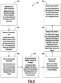
- FIGURE 4 generally depicts a method 250 for improving in-car speech intelligibility and reducing noise pollution as executed by controller 202 the loudspeaker array 102 of the road-alert system in accordance with one embodiment.
- the loudspeaker array 102 receives a recorded announcement (or audio output to be provided).
- the loudspeaker array 102 may be wirelessly coupled to the server 109 via a network connection and receive a command from the server 109 to transmit the recorded announcement to any number of vehicles 104 that drive by.
- the loudspeaker array 102 may include any number of transceivers 111 for wirelessly receiving commands from the server.
- the transceivers 111 may be used in connection with IEEE 802.3 (e.g., Ethernet), IEEE 802.11 (e.g., WIFI), analog audio signals, Pulse-Code Modulation (PCM) audio, Audio Engineering Society digital audio (e.g., AES3 digital audio, AES10 digital audio, or AES67 packetized digital audio), Dante Multichannel IP Audio, etc.
- IEEE 802.3 e.g., Ethernet
- IEEE 802.11 e.g., WIFI
- analog audio signals e.g., analog audio signals
- PCM Pulse-Code Modulation
- Audio Engineering Society digital audio e.g., AES3 digital audio, AES10 digital audio, or AES67 packetized digital audio
- Dante Multichannel IP Audio etc.
- the controller 202 applies specialized equalization parameters to the audio output based on the measurements obtained vehicle(s) to obtain the average in-car noise characteristic.
- the average in-car noise characteristic takes into account the transmission loss attributed to the vehicle 104 and road and engine noise that may be experienced in the vehicle 104. This aspect increases the in-car intelligibility of the audio output when the audio output enters into a cabin of the vehicle 104.
- the controller 202 applies beamforming parameters to minimize noise pollution.
- the controller 202 focuses the dispersion of the audio output onto a smaller target area to reduce noise pollution in the outside or exterior open environment.
- the controller 202 may selectively (i) delay the transmission of the recorded audio from any one or more of the loudspeaker elements 103 in the loudspeaker array 102, (ii) play the recorded audio from any one or more of the loudspeaker elements 103 in the loudspeaker array 102 at different volumes, and/or (iii) employ cancellation effects at the one or more loudspeaker elements 103.
- These different loudspeaker settings allow the loudspeaker array 102 to control the size, shape, and direction of the transmitted recorded audio output.
- the controller 202 transmits the recorded audio output to the various loudspeaker elements 103 in the array 102 to provide the recorded audio output (or recorded announcement) to the vehicle 104.
- FIGURE 5 generally depicts a block diagram 300 for the controller 202 of the loudspeaker array 102 in accordance with one embodiment.
- the controller 202 generally includes an audio player 302, an equalization digital signal processor (DSP) 304, a beamforming DSP 306, a plurality of amplifiers 308, and the loudspeaker elements 103).
- the audio player 302 receives the recorded message and provides a digital version of the recorded audio output to the equalization DSP 304.
- the equalization DSP 304 applies the equalization parameters to the audio output based on the measurements obtained from the vehicle(s) to obtain the average in-car noise characteristic.
- the average in-car noise characteristic takes into account transmission loss attributed to the vehicle 104 and road and engine noise that may be experienced in the vehicle 104 This aspect increases the in-car intelligibility of the audio output when the audio output enters into a cabin of the vehicle 104.
- the beamforming DSP 306 may selectively (i) delay the transmission of the recorded audio from any one or more of the loudspeaker elements 103 in the loudspeaker array 102, (ii) play the recorded audio from any one or more of the loudspeaker elements 103 in the loudspeaker array 102 at different volumes, and/or (iii) employ cancellation effects at the one or more loudspeaker elements 103.
- these different loudspeaker settings allow the loudspeaker array 102 to control the size, shape, and direction of the transmitted recorded audio output.
- the individual amplifiers 308 may amplify various audio inputs that correspond to the recorded audio output based on control signals provided by the beamforming DSP 306. This aspect enables the system 300 to control the volume of the recorded audio output as played back by the individual loudspeaker elements 103.
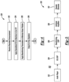
- FIGURE 6 generally depicts a process diagram 350 for improving in-car speech intelligibility and reducing noise pollution as executed by a loudspeaker array 102 of the road-alert system 100 in accordance with one embodiment.
- the in-car noise environment is measured at the vehicle 104.
- measurements are performed at the car to assess road and engine noise that may be experience within the interior of the vehicle 104 or otherwise experienced by driver.
- the measurements may be performed from a number of vehicles to determine the average background noise that a driver will experience.
- the transmission loss is determined at the vehicle 104.
- loudspeakers may be placed outside of a number of vehicles and the received audio may then be measured inside the vehicle 104. This step determines the audio loss that may occur through the windscreen and other aspects of the exterior shell of the vehicle 104.
- an ideal incident sound field may be determined.
- the most ideal (or best) incident audio is ascertained to provide the maximum STI in the vehicle 104.
- the effective noise floor it is then possible to calculate the frequency characteristics of the sound (e.g., warning) that is arriving at the vehicle 104 (or being heard by the driver of the vehicle 104) from the loudspeaker array 102.
- the original "untuned signal" from the loudspeaker array 102 is attenuated non-linearly by the vehicle's exterior (e.g., windshield,etc.), which results in a certain "Transmission Loss".
- This attenuated signal then needs to compete with the surrounding road/engine noise.
- the loudspeaker array 102 is required to meet a minimum signal-to-noise ratio (SNR) at every frequency band. Therefore, the equalization parameters of the loudspeaker array 102 needs to first correct the non-linear transmission loss, then increase gain in specific frequency bands to overcome noise (i.e., to meet the minimum SNR), and finally smooth the overall frequency response.
- SNR signal-to-noise ratio
- a distance of the loudspeaker throw is determined.
- a message time for example, 4 seconds (or a four second message time) and the speed limit of the highway
- a determination may be made that the message needs to be audible, for example, for 100 m from an entrance of the tunnel.
- the speed limit of highways in Japan is 100 km/h.
- a short message may typically be about 4 seconds in length. This provides about 100m of road traveled by the vehicle 104 as the vehicle 104 approaches the tunnel.
- the SPL for the distance determined at step 358 is determined.
- the incident sound field is generally defined as the sound that arrives at the outside (or exterior) of the vehicle 104 (e.g., before the transmission loss or competition with the road noise).
- the incident sound field may be considered the sound that contacts the windscreen of the vehicle 104).
- the SPL may need to be 90 dB as a target.
- the noise pollution is minimized.
- memory of the controller 202 may store the SPL (e.g., 90 dB) as determined at step 364 and equalization settings or parameters to generate an ideal incident sound field.
- the controller 202 may be programmed to avoid creating noise pollution by setting quiet zones for the software executed by the controller 202..
- the disclosed loudspeaker array 102 differs from a traditional horn in two ways. First, by the length of the sound field. For example, to obtain a narrow angle such as the angle achieved with the loudspeaker array 102 which may be, for example, 5 degrees, the horn would need to be very long, which would be impractical. Second by the frequency response. Horn-type based loudspeakers generally do not yield an optimized frequency response. In this regard, it would not be possible to achieve the same STI ratings as provided by the disclosed loudspeaker array 102. As noted above, the controller 202 may generate a beam of audio by adjusting the individual phasing of each of the loudspeaker elements (or the plurality of loudspeakers 103) in the array 102 (using constructive and destructive interference). This aspect enables for the sound to be "steered" into a very tight beam from the loudspeaker array 102. Thus, in this regard, the energy is steered only on the road 106, and not into the surroundings.
- beamforming parameters are applied.
- the controller 202 executes beamforming parameters to control the loudspeaker elements 103 of the loudspeaker array 102 to transmit the recorded message at a lower dispersion to the desired target (e.g., the vehicle 104).
- FIGURE 7 generally depicts a plurality of sound pressure level "SPL" heat maps 400a - 400d for various road alert systems (or audio sources that provided a recorded message to the vehicle).
- a heat map for a generic folded horn is generally shown at 400a.
- the heat map 400a for the generic folded horn illustrates a wide dispersion of the audio output (or recorded message) as provided by the generic folded horn relative to the road 106.
- a heat map for a generic point source is generally shown at 400b.
- the heat map 400b for the generic point source illustrates a narrow dispersion of the audio output at a low amplitude or intensity.
- a point source loudspeaker may be approximated by a single sound source that radiates out in a predictable pattern such as loudspeaker in a home or a paging loudspeaker at a restaurant where the sound is originates from a "point".
- the point source loudspeaker differs from the loudspeaker array 102 where all the loudspeaker elements 103 work together to from more of a cylindrical wavefront. Thus, instead of all the sound radiating from a "point", the sound radiates from a from a "line”.
- a heat map for one loudspeaker array is generally shown at 400c.
- the loudspeaker array may be implemented as a JBL Intellivox ® array and does not include the equalization and beamformer characteristics.
- the heat map 400c for the JBL Intellivox ® array illustrates a medium dispersion of the audio output at a very strong amplitude. While the dispersion of the audio output from the JBL Intellivox ® array may be narrower than that illustrated with respect to the folded horn as shown at 400a, the dispersion of the audio output from the can be seen to overlap over the road 106 and extend onto portions of land adjacent to the road 106.
- a heat map for the loudspeaker array 102 that employs equalization parameters and beamforming is generally shown at 400d.
- the heat map 400d for the loudspeaker array 102 illustrates a narrow dispersion of the audio output in comparison to that illustrated for the folded horn at 400a and the JBL Intellivox ® array at 400c that does not include the equalization parameters or the beamforming. This condition minimizes the amount of noise pollution that may be disbursed in the environment 108.
- the loudspeaker array 102 exhibits an adequate level of amplitude for the audio output on the road 106.
- FIGURE 8 generally depicts a table 500 that illustrates noise pollution relative to various audio sources (e.g., folded horn, point source, JBL Intellivox array ® without equalization and beamforming capability, and the loudspeaker array 102 that incorporates equalization parameters and beamforming).
- various audio sources e.g., folded horn, point source, JBL Intellivox array ® without equalization and beamforming capability, and the loudspeaker array 102 that incorporates equalization parameters and beamforming.
- the point source provides a high noise pollution at roughly 85.0 dBA.
- the JBL Intellivox array without equalization and beamforming generally exhibits the lowest noise pollution from out of the audio sources.
- An aspect to take into account is the difference between the SPL on the road 106 and the SPL at the at least one residence and/or at least one commercial business 110.
- the message needs to reach the car at about 96dB//SPL.
- the loudspeaker array 102 may achieve 96dB on the road 106 while only having about 70dB(a) outside or off of the road.
- the loudspeaker elements 103 provides a warning that may reach 96dB//SPL on the road 106 the volume (or additional loudspeaker elements 103 are added).
- the noise pollution may scale with the volume on the road 106, this may entail that there is more noise pollution in order to provide the warning or message across.
- the loudspeaker array 102 can be steered via beamforming, the loudspeaker array 102 may have a consistent volume the entire way that the warning travels towards the tunnel.
- FIGURE 9 generally depicts a table that illustrates an in-car Speech Transmission Index (STI) rating and IEC quality factor for the audio sources (e.g., folded horn, point source, JBL Intellivox array ® without equalization and beamforming capability, and the loudspeaker array 102 that incorporates equalization parameters and beamforming).
- the folded horn speaker exhibits extremely poor in-car STI rating.
- the point source achieves favorable in-car STI rating at the expense of high noise pollution (e.g., see FIGURE 8 ).
- the JBL Intellivox array ® without equalization and beamforming capabilities exhibits a very low SPL due to lack of headroom which compromises the in-car STI rating.
- the loudspeaker array 102 with equalization and beamforming capabilities exhibits the highest in-car STI rating and also provides approximately 17 - 20dB lower noise pollution compared to the generic point source (e.g., see Table 500) which is the only other audio source with a comparable in-car STI rating.
- the JBL Intellivox array ® without equalization and beamforming capabilities outputs frequencies that are redundant to STI. Therefore, the input wattage is being distributed over a large range of frequencies which provides the limited SPL.
- the loudspeaker array 102 with the equalization and beamforming capabilities provides frequencies that are essential for STI. Thus, given the same input wattage, the power is focused onto these essential frequencies thereby providing more STI.
Landscapes
- Physics & Mathematics (AREA)
- Engineering & Computer Science (AREA)
- General Physics & Mathematics (AREA)
- Signal Processing (AREA)
- Acoustics & Sound (AREA)
- Analytical Chemistry (AREA)
- Chemical & Material Sciences (AREA)
- Health & Medical Sciences (AREA)
- Computer Networks & Wireless Communication (AREA)
- General Health & Medical Sciences (AREA)
- Otolaryngology (AREA)
- Computational Linguistics (AREA)
- Quality & Reliability (AREA)
- Audiology, Speech & Language Pathology (AREA)
- Human Computer Interaction (AREA)
- Multimedia (AREA)
- Fittings On The Vehicle Exterior For Carrying Loads, And Devices For Holding Or Mounting Articles (AREA)
Abstract
Description
- Aspects disclosed herein generally relate to a system and method for road alert systems. More specifically, aspects disclosed herein relate to a system and method for road alert system to improve in-car speech intelligibility and reduce noise pollution.
- Any number of loudspeaker arrays may be positioned in front of a tunnel that is configured to generate audible alerts to a vehicle prior to entry of the vehicle into the tunnel. Such loudspeaker arrays may be known as road alert speaker systems. The loudspeaker arrays are configured to provide audible warnings to a driver of the vehicle prior to entry into the tunnel. The audible warning may include a message pertaining to lane closure, command to activate headlights, no passing onto other lanes, etc. Alternatively, some road alert system may provide a repetitive beeping alert to warn the driver of a condition regarding the tunnel. Due to road noise or other factors, these messages or tones may not be heard by the driver. Conventional road alert systems may be unable to perform adequately in both speech intelligibility and noise pollution.
- In at least one embodiment, a road alert system is provided. The system includes a loudspeaker array and at least one controller. The loudspeaker array transmits an audio output signal to a vehicle traveling on a road. The at least one controller is programmed to receive a message indicative of a warning for the vehicle for transmission on the audio output signal and to apply equalization parameters to the message to increase in-vehicle speech intelligibility of the audio output signal within the vehicle. The at least one controller is further programmed to transmit the audio output signal via the loudspeaker array in a beamforming mode to minimize noise pollution for objects positioned along the road.
- In at least another embodiment, a method for transmitting an alert to a vehicle on a road is provided. The method includes transmitting, via a loudspeaker array, an audio output signal to a vehicle traveling on the road; and receiving, at at least one controller, a message indicative of a warning for the vehicle for transmission on the audio output signal. The method further includes applying equalization parameters to the message to increase in-vehicle speech intelligibility of the audio output signal within the vehicle; and transmitting the audio output signal via the loudspeaker array in a beamforming mode to minimize noise pollution for objects positioned along the road.
- In at least another embodiment, a computer-program product embodied in a non-transitory computer readable medium that is programmed for transmitting an alert to a vehicle on a road is provided. The computer-program product includes instructions for transmitting, via a loudspeaker array, an audio output signal to a vehicle traveling on the road; and for receiving, at at least one controller, a message indicative of a warning for the vehicle for transmission on the audio output signal. The computer-program product includes instructions for applying equalization parameters to the message to increase in-vehicle speech intelligibility of the audio output signal within the vehicle; and transmitting the audio output signal via the loudspeaker array in a beamforming mode to minimize noise pollution for objects positioned about along the road.
- The embodiments of the present disclosure are pointed out with particularity in the appended claims. However, other features of the various embodiments will become more apparent and will be best understood by referring to the following detailed description in conjunction with the accompany drawings in which:
-
FIGURE 1 generally depicts one example of a road alert system; -
FIGURE 2 generally depicts another example of a road alert system that employs beamforming and optimized tuning in accordance with one embodiment; -
FIGURE 3 generally depicts another example of the road alert system in accordance with one embodiment; -
FIGURE 4 generally depicts a method for improving in-car speech intelligibility and reducing noise pollution as executed by a loudspeaker array of the road-alert system in accordance with one embodiment; -
FIGURE 5 generally depicts a block diagram for a controller of the loudspeaker array in accordance with one embodiment; -
FIGURE 6 generally depicts a process diagram for improving in-car speech intelligibility and reducing noise pollution as executed by a loudspeaker array of the road-alert system in accordance with one embodiment; -
FIGURE 7 generally depicts a plurality of sound pressure level "SPL" heat maps for various road alert systems; -
FIGURE 8 generally depicts a table that illustrates noise pollution relative to various road alert systems; and -
FIGURE 9 generally depicts a table that illustrates an in-car Speech Transmission Index (STI) rating and IEC quality factor for various road alert systems. - As required, detailed embodiments of the present invention are disclosed herein; however, it is to be understood that the disclosed embodiments are merely exemplary of the invention that may be embodied in various and alternative forms. The figures are not necessarily to scale; some features may be exaggerated or minimized to show details of particular components. Therefore, specific structural and functional details disclosed herein are not to be interpreted as limiting, but merely as a representative basis for teaching one skilled in the art to variously employ the present invention.
- It is recognized that the controllers/devices as disclosed herein and in the attached Appendix may include any number of microprocessors, integrated circuits, memory devices (e.g., FLASH, random access memory (RAM), read only memory (ROM), electrically programmable read only memory (EPROM), electrically erasable programmable read only memory (EEPROM), or other suitable variants thereof), and software which co-act with one another to perform operation(s) disclosed herein. In addition, such controllers as disclosed utilizes one or more microprocessors to execute a computer-program that is embodied in a non-transitory computer readable medium that is programmed to perform any number of the functions as disclosed. Further, the controller(s) as provided herein includes a housing and the various number of microprocessors, integrated circuits, and memory devices ((e.g., FLASH, random access memory (RAM), read only memory (ROM), electrically programmable read only memory (EPROM), electrically erasable programmable read only memory (EEPROM)) positioned within the housing. The controller(s) as disclosed also include hardware-based inputs and outputs for receiving and transmitting data, respectively from and to other hardware-based devices as discussed herein.
- Conventional road alert loudspeaker systems may be unable to perform adequately in both speech intelligibility and noise pollution. Systems that are able to achieve reasonable in-car speech intelligibility do so at the cost of excessive noise pollution. Conversely, systems that limit noise pollution may not achieve sufficient in-car speech intelligibility to be use usable.
- Current implementations of road alert systems may be further limited in a number of ways. For example, extremely high sound pressure level (SPL) output may be needed to achieve reasonable speech intelligibility inside moving vehicles due to transmission loss and in-car noise. In order to achieve this high SPL output, bulky roadside loudspeakers and power amplifiers may be needed. These devices severely compromise portability, energy efficiency, and costeffectiveness of the system. For example, some speaker arrays that may compromise portability may be nearly 6 m long and includes two units. While in some regards, this may be considered portable, a single person cannot carry such a system.
- Without a specialized speaker equalization (EQ), the loudspeaker outputs a plurality of frequencies that may not be essential for speech intelligibility, which further decreases efficiency. Due to limited in-car intelligibility, messages are either repeated or replaced with klaxons which can be jarring.
- In addition, conventional road alert systems may provide excessive noise pollution to surrounding areas, typically residential areas, due to lack of sound dispersion control. In enclosed areas such as tunnels and parking structures, uncontrolled dispersion results in excess reverberation, which worsens speech intelligibility and noise pollution. In open areas such as arterial roads, excess frequencies that are present in speech (i.e., but not essential for intelligibility) add to noise pollution in surrounding areas.
- The example road alert systems as disclosed herein may generally simultaneously improve in-car speech intelligibility and reduce noise pollution. In addition, by optimizing the output of the loudspeaker for in-car speech intelligibility using the specialized loudspeaker EQ, redundant output may be eliminated. This condition enables the loudspeaker itself to be more efficient. This in turn makes the system more portable, energy efficient, and cost effective. Using a digital signal processor (DSP) based array beamforming in a line array loudspeaker eliminates the need for bulky horns as a mechanism for controlling directivity. This reduces the overall mass and the size of the loudspeaker system, thereby reducing integration complexity and improving portability. This may apply to a system that had a similar SPL inside the vehicle. Most conventional systems aim for a lower volume with the desire that the driver hears the warnings. In enclosed spaces, the array beamforming as set forth herein also reduces unwanted reflections, thereby lowering reverberation time. This effect compounds the improvements to speech intelligibility and noise pollution.
- Aspects disclosed herein generally provide a road alert system that employs a specialized speaker tuning implementation. For example, the specialized speaker tuning implementation may include speaker equalization and array beamforming. At least one controller positioned on a loudspeaker array of the road alert system may execute the speaker equalization and array beamforming. The specialized speaker tuning may optimize in-car speech intelligibility for the warning issued to the driver in the vehicle. The array beamforming focuses the audible warning onto a target area and minimizes noise pollution in surrounding areas, such as roadside residential areas.
-
FIGURE 1 generally depicts one example of aroad alert system 100. Thesystem 100 generally includes at least one loudspeaker array 102 (or the loudspeaker array 102) and avehicle 104. As shown, theloudspeaker array 102 may be positioned near aroad 106 or another path that enables thevehicle 104 to drive thereon. Theloudspeaker array 102 is generally positioned in an outside or exterioropen environment 108 with respect to thevehicle 104. Theloudspeaker array 102 is programmed to transmit audible warnings to thevehicle 104. Theloudspeaker array 102 may receive a recorded message from a server 109 to transmit as the audible warning to thevehicle 104. For example, theloudspeaker array 102 may include any number of transceivers 111 for receiving the recorded message from the server 109. It is also recognized that theloudspeaker array 102 may also directly receive a memory card (not shown) that includes the recorded message for playback or transmission to thevehicle 104. - In one example, the
loudspeaker array 102 may be positioned proximate to a tunnel to provide audible warnings or alerts to a driver of thevehicle 104. It is recognized that theloudspeaker array 102 may be positioned in an area of the environment and that theloudspeaker array 102 doesn't necessarily have to be used in connection with transmitting audible warnings to thevehicle 104 for purposes of warning the driver of aspects related to the tunnel. Any warnings may be transmitted for the purpose of simply alerting a drive in thevehicle 104 from any location in the exterioropen environment 108 about any road hazard or obstacle that thevehicle 104 may encounter while traveling on theroad 106. Theloudspeaker array 102 generally includes a plurality of loudspeakers (or speaker elements) 103 arranged therein for transmitting the audible warnings. - The
road alert system 100 generally illustrates various problems with respect to someloudspeaker array 102 implementations. For example, theloudspeaker array 102 transmits a wide dispersion of the audio-based warning and that when such a warning reaches thevehicle 104, the audible warning carries poor intelligibility and the driver of thevehicle 104 may not be able to actually hear (or understand) the warning. For example, in this case, the driver may hear a distorted version of the warning and may not be able to discern the meaning over the road noise. In addition, theloudspeaker array 102 transmits the audio warning (or audio output) at a high SPL. This coupled with the high dispersion area leads to noise leakage and disturbs at least one residence and/or at least onecommercial business 110. -
FIGURE 2 generally depicts another example of aroad alert system 150 in accordance with one embodiment. In thesystem 150, theloudspeaker array 102 includes at least one controller 202 (hereafter "thecontroller 202"). Thecontroller 202 is programmed to perform application specific tuning (or optimized tuning) and beamforming. Thecontroller 202 applies the application specific tuning (or employs loudspeaker equalization) to optimize in-car (or in-vehicle) speech intelligibility for the warning issued to the driver in thevehicle 104. Thecontroller 202 applies the beamforming to reduce the wide dispersion of the audible warning onto a smaller target area that includes thevehicle 104 and minimizes noise pollution in surrounding areas, such as roadside residential areas. -
FIGURE 3 generally depicts another example of theroad alert system 150 in accordance with one embodiment. Thesystem 150 as illustrated inFIGURE 3 illustrates that the tuned audio as received at thevehicle 104 is optimized for speech (e.g., speech in thevehicle 104 is intelligible) while taking into account transmission loss due to the vehicle itself including sheet metal, glass, etc. and environmental noise such as, but not limited to, road and engine noise that act to otherwise impede or prevent the audible alert from reaching the driver of thevehicle 104. The speaker equalization as performed by thecontroller 202 enables the in-car speech intelligibility to achieve an in-car (or in-vehicle) Speech Transmission Index (STI) rating of at least 0.6 which generally corresponds to "Good" intelligibility according to the IEC 60268-16 standard. - In general, the equalization parameters employed by the
controller 202 is based on measurements performed on a number of different models and makes of vehicles. For example, in-car noise (e.g., road and engine noise) was measured from 10 vehicles of various makes and sizes to achieve an average in-car noise characteristic. Similarly, a transmission loss of vehicles (e.g., due to sheet metal or exterior shell of the vehicle 104) was obtained from measuring 12 vehicles of various makes and sizes to derive an average transmission loss characteristic. Once the in-car noise characteristic and the transmission characteristic are obtained, it is possible to establish tuning parameters (or apply equalization) on the audible output to ensure in-car intelligibility of the audio in thevehicle 104 while taking into account transmission loss and road and engine noise. -
FIGURE 4 generally depicts amethod 250 for improving in-car speech intelligibility and reducing noise pollution as executed bycontroller 202 theloudspeaker array 102 of the road-alert system in accordance with one embodiment. - In
operation 252, theloudspeaker array 102 receives a recorded announcement (or audio output to be provided). For example, theloudspeaker array 102 may be wirelessly coupled to the server 109 via a network connection and receive a command from the server 109 to transmit the recorded announcement to any number ofvehicles 104 that drive by. As noted above, it is recognized that theloudspeaker array 102 may include any number of transceivers 111 for wirelessly receiving commands from the server. In one example, the transceivers 111 may be used in connection with IEEE 802.3 (e.g., Ethernet), IEEE 802.11 (e.g., WIFI), analog audio signals, Pulse-Code Modulation (PCM) audio, Audio Engineering Society digital audio (e.g., AES3 digital audio, AES10 digital audio, or AES67 packetized digital audio), Dante Multichannel IP Audio, etc. - In
operation 254, thecontroller 202 applies specialized equalization parameters to the audio output based on the measurements obtained vehicle(s) to obtain the average in-car noise characteristic. As noted above, the average in-car noise characteristic takes into account the transmission loss attributed to thevehicle 104 and road and engine noise that may be experienced in thevehicle 104. This aspect increases the in-car intelligibility of the audio output when the audio output enters into a cabin of thevehicle 104. - In
operation 256, thecontroller 202 applies beamforming parameters to minimize noise pollution. As noted above, thecontroller 202 focuses the dispersion of the audio output onto a smaller target area to reduce noise pollution in the outside or exterior open environment. For example, to perform the beamforming, thecontroller 202 may selectively (i) delay the transmission of the recorded audio from any one or more of theloudspeaker elements 103 in theloudspeaker array 102, (ii) play the recorded audio from any one or more of theloudspeaker elements 103 in theloudspeaker array 102 at different volumes, and/or (iii) employ cancellation effects at the one ormore loudspeaker elements 103. These different loudspeaker settings allow theloudspeaker array 102 to control the size, shape, and direction of the transmitted recorded audio output. - In
operation 258, thecontroller 202 transmits the recorded audio output to thevarious loudspeaker elements 103 in thearray 102 to provide the recorded audio output (or recorded announcement) to thevehicle 104. -
FIGURE 5 generally depicts a block diagram 300 for thecontroller 202 of theloudspeaker array 102 in accordance with one embodiment. Thecontroller 202 generally includes anaudio player 302, an equalization digital signal processor (DSP) 304, abeamforming DSP 306, a plurality ofamplifiers 308, and the loudspeaker elements 103). Theaudio player 302 receives the recorded message and provides a digital version of the recorded audio output to theequalization DSP 304. Theequalization DSP 304 applies the equalization parameters to the audio output based on the measurements obtained from the vehicle(s) to obtain the average in-car noise characteristic. As noted above, the average in-car noise characteristic takes into account transmission loss attributed to thevehicle 104 and road and engine noise that may be experienced in thevehicle 104 This aspect increases the in-car intelligibility of the audio output when the audio output enters into a cabin of thevehicle 104. - The
beamforming DSP 306 may selectively (i) delay the transmission of the recorded audio from any one or more of theloudspeaker elements 103 in theloudspeaker array 102, (ii) play the recorded audio from any one or more of theloudspeaker elements 103 in theloudspeaker array 102 at different volumes, and/or (iii) employ cancellation effects at the one ormore loudspeaker elements 103. As noted above, these different loudspeaker settings allow theloudspeaker array 102 to control the size, shape, and direction of the transmitted recorded audio output. Theindividual amplifiers 308 may amplify various audio inputs that correspond to the recorded audio output based on control signals provided by thebeamforming DSP 306. This aspect enables thesystem 300 to control the volume of the recorded audio output as played back by theindividual loudspeaker elements 103. -
FIGURE 6 generally depicts a process diagram 350 for improving in-car speech intelligibility and reducing noise pollution as executed by aloudspeaker array 102 of the road-alert system 100 in accordance with one embodiment. - At
step 352, the in-car noise environment is measured at thevehicle 104. As noted above., measurements are performed at the car to assess road and engine noise that may be experience within the interior of thevehicle 104 or otherwise experienced by driver. The measurements may be performed from a number of vehicles to determine the average background noise that a driver will experience. - At
step 354, the transmission loss is determined at thevehicle 104. For example, loudspeakers may be placed outside of a number of vehicles and the received audio may then be measured inside thevehicle 104. This step determines the audio loss that may occur through the windscreen and other aspects of the exterior shell of thevehicle 104. - At
step 356, an ideal incident sound field may be determined. By convolving the in-car noise and transmission loss as determines insteps vehicle 104. By understanding the effective noise floor as noted above, it is then possible to calculate the frequency characteristics of the sound (e.g., warning) that is arriving at the vehicle 104 (or being heard by the driver of the vehicle 104) from theloudspeaker array 102. - For example, the original "untuned signal" from the
loudspeaker array 102 is attenuated non-linearly by the vehicle's exterior (e.g., windshield,etc.), which results in a certain "Transmission Loss". This attenuated signal then needs to compete with the surrounding road/engine noise. To achieve high STI, theloudspeaker array 102 is required to meet a minimum signal-to-noise ratio (SNR) at every frequency band. Therefore, the equalization parameters of theloudspeaker array 102 needs to first correct the non-linear transmission loss, then increase gain in specific frequency bands to overcome noise (i.e., to meet the minimum SNR), and finally smooth the overall frequency response. - At
step 358, a distance of the loudspeaker throw is determined. By using a message time of, for example, 4 seconds (or a four second message time) and the speed limit of the highway, a determination may be made that the message needs to be audible, for example, for 100 m from an entrance of the tunnel. For example, the speed limit of highways in Japan is 100 km/h. A short message may typically be about 4 seconds in length. This provides about 100m of road traveled by thevehicle 104 as thevehicle 104 approaches the tunnel. - At
step 360, based on an incident sound field, the SPL for the distance determined atstep 358 is determined. The incident sound field is generally defined as the sound that arrives at the outside (or exterior) of the vehicle 104 (e.g., before the transmission loss or competition with the road noise). The incident sound field may be considered the sound that contacts the windscreen of the vehicle 104). Assuming that the distance of thevehicle 104 from the tunnel (or other obstacle) is 100 meters, the SPL may need to be 90 dB as a target. - At
step 362, the noise pollution is minimized. For example, memory of thecontroller 202 may store the SPL (e.g., 90 dB) as determined atstep 364 and equalization settings or parameters to generate an ideal incident sound field. In addition, thecontroller 202 may be programmed to avoid creating noise pollution by setting quiet zones for the software executed by thecontroller 202.. - The disclosed
loudspeaker array 102 differs from a traditional horn in two ways. First, by the length of the sound field. For example, to obtain a narrow angle such as the angle achieved with theloudspeaker array 102 which may be, for example, 5 degrees, the horn would need to be very long, which would be impractical. Second by the frequency response. Horn-type based loudspeakers generally do not yield an optimized frequency response. In this regard, it would not be possible to achieve the same STI ratings as provided by the disclosedloudspeaker array 102. As noted above, thecontroller 202 may generate a beam of audio by adjusting the individual phasing of each of the loudspeaker elements (or the plurality of loudspeakers 103) in the array 102 (using constructive and destructive interference). This aspect enables for the sound to be "steered" into a very tight beam from theloudspeaker array 102. Thus, in this regard, the energy is steered only on theroad 106, and not into the surroundings. - At
step 364, beamforming parameters are applied. For example, thecontroller 202 executes beamforming parameters to control theloudspeaker elements 103 of theloudspeaker array 102 to transmit the recorded message at a lower dispersion to the desired target (e.g., the vehicle 104). -
FIGURE 7 generally depicts a plurality of sound pressure level "SPL"heat maps 400a - 400d for various road alert systems (or audio sources that provided a recorded message to the vehicle). A heat map for a generic folded horn is generally shown at 400a. Theheat map 400a for the generic folded horn illustrates a wide dispersion of the audio output (or recorded message) as provided by the generic folded horn relative to theroad 106. A heat map for a generic point source is generally shown at 400b. Theheat map 400b for the generic point source illustrates a narrow dispersion of the audio output at a low amplitude or intensity. A point source loudspeaker may be approximated by a single sound source that radiates out in a predictable pattern such as loudspeaker in a home or a paging loudspeaker at a restaurant where the sound is originates from a "point". - The point source loudspeaker differs from the
loudspeaker array 102 where all theloudspeaker elements 103 work together to from more of a cylindrical wavefront. Thus, instead of all the sound radiating from a "point", the sound radiates from a from a "line". - A heat map for one loudspeaker array is generally shown at 400c. The loudspeaker array may be implemented as a JBL Intellivox ® array and does not include the equalization and beamformer characteristics. The
heat map 400c for the JBL Intellivox ® array illustrates a medium dispersion of the audio output at a very strong amplitude. While the dispersion of the audio output from the JBL Intellivox ® array may be narrower than that illustrated with respect to the folded horn as shown at 400a, the dispersion of the audio output from the can be seen to overlap over theroad 106 and extend onto portions of land adjacent to theroad 106. - A heat map for the
loudspeaker array 102 that employs equalization parameters and beamforming is generally shown at 400d. Theheat map 400d for theloudspeaker array 102 illustrates a narrow dispersion of the audio output in comparison to that illustrated for the folded horn at 400a and the JBL Intellivox ® array at 400c that does not include the equalization parameters or the beamforming. This condition minimizes the amount of noise pollution that may be disbursed in theenvironment 108. In addition, theloudspeaker array 102 exhibits an adequate level of amplitude for the audio output on theroad 106. -
FIGURE 8 generally depicts a table 500 that illustrates noise pollution relative to various audio sources (e.g., folded horn, point source, JBL Intellivox array ® without equalization and beamforming capability, and theloudspeaker array 102 that incorporates equalization parameters and beamforming). As shown, the point source provides a high noise pollution at roughly 85.0 dBA. The JBL Intellivox array without equalization and beamforming generally exhibits the lowest noise pollution from out of the audio sources. - An aspect to take into account is the difference between the SPL on the
road 106 and the SPL at the at least one residence and/or at least onecommercial business 110. In order to be audible, the message needs to reach the car at about 96dB//SPL. Due to the beam steering and the equalization parameters, theloudspeaker array 102 may achieve 96dB on theroad 106 while only having about 70dB(a) outside or off of the road. Theloudspeaker elements 103 provides a warning that may reach 96dB//SPL on theroad 106 the volume (oradditional loudspeaker elements 103 are added). However, since the noise pollution may scale with the volume on theroad 106, this may entail that there is more noise pollution in order to provide the warning or message across. Also, since the point source/folded horn speakers "drop off' quickly, a level of 96dB at the 100 m point entails that the level near the tunnel entrance may be much higher. However, theloudspeaker array 102 can be steered via beamforming, theloudspeaker array 102 may have a consistent volume the entire way that the warning travels towards the tunnel. -
FIGURE 9 generally depicts a table that illustrates an in-car Speech Transmission Index (STI) rating and IEC quality factor for the audio sources (e.g., folded horn, point source, JBL Intellivox array ® without equalization and beamforming capability, and theloudspeaker array 102 that incorporates equalization parameters and beamforming). The folded horn speaker exhibits extremely poor in-car STI rating. The point source achieves favorable in-car STI rating at the expense of high noise pollution (e.g., seeFIGURE 8 ). The JBL Intellivox array ® without equalization and beamforming capabilities exhibits a very low SPL due to lack of headroom which compromises the in-car STI rating. Theloudspeaker array 102 with equalization and beamforming capabilities exhibits the highest in-car STI rating and also provides approximately 17 - 20dB lower noise pollution compared to the generic point source (e.g., see Table 500) which is the only other audio source with a comparable in-car STI rating. The JBL Intellivox array ® without equalization and beamforming capabilities outputs frequencies that are redundant to STI. Therefore, the input wattage is being distributed over a large range of frequencies which provides the limited SPL. Conversely, theloudspeaker array 102 with the equalization and beamforming capabilities provides frequencies that are essential for STI. Thus, given the same input wattage, the power is focused onto these essential frequencies thereby providing more STI. - While exemplary embodiments are described above, it is not intended that these embodiments describe all possible forms of the invention. Rather, the words used in the specification are words of description rather than limitation, and it is understood that various changes may be made without departing from the spirit and scope of the invention. Additionally, the features of various implementing embodiments may be combined to form further embodiments of the invention.
Claims (15)
- A road alert system, the system comprising:a loudspeaker array for transmitting an audio output signal to a vehicle traveling on a road; andat least one controller programmed to:receive a message indicative of a warning for the vehicle for transmission on the audio output signal;apply equalization parameters to the message to increase in-vehicle speech intelligibility of the audio output signal within the vehicle; andtransmit the audio output signal via the loudspeaker array in a beamforming mode to minimize noise pollution for objects positioned along the road.
- The system of claim 1, wherein the at least one controller is further programmed to apply the equalization parameters to the message prior to transmitting the audio output signal in the beamforming mode.
- The system of claim 1, wherein the equalization parameters are based on at least measured vehicle noise from a plurality of vehicles and an average transmission loss characteristic as established from the plurality of vehicles.
- The system of claim 3, wherein the average transmission loss characteristic is based on transmission losses for each vehicle attributed to at least an exterior shell for each of the vehicles.
- The system of claim 3, wherein the measured vehicle noise is based on environmental noise exhibited on each of the plurality of vehicles.
- The system of claim 1, wherein the at least one controller is further programmed to control at least one of a size, shape, and direction of the transmitted audio output signal in the beamforming mode.
- The system of claim 1, wherein the at least one controller is further programmed to at least one of: (i) delay transmission of the audio output signal from any one or more loudspeakers positioned in the loudspeaker array, (ii) playback the audio output signal at one or more different volumes through the loudspeakers array, or (iii) employ cancellation effects at the one or more loudspeakers of the loudspeaker array while transmitting the audio output signal.
- A method for transmitting an alert to a vehicle on a road, the method comprising:transmitting, via a loudspeaker array, an audio output signal to a vehicle traveling on the road; andreceiving, at at least one controller, a message indicative of a warning for the vehicle for transmission on the audio output signal;applying equalization parameters to the message to increase in-vehicle speech intelligibility of the audio output signal within the vehicle; andtransmitting the audio output signal via the loudspeaker array in a beamforming mode to minimize noise pollution for objects positioned along the road.
- The method of claim 8, wherein applying the equalization parameters to the message is performed prior to transmitting the audio output signal in the beamforming mode.
- The method of claim 8, wherein the equalization parameters are based on at least measured vehicle noise from a plurality of vehicles and an average transmission loss characteristic as established from the plurality of vehicles.
- The method of claim 10, wherein the average transmission loss characteristic is based on transmission losses for each vehicle attributed to at least an exterior shell for each of the vehicles.
- The method of claim 10, wherein the measured vehicle noise is based on environmental noise exhibited on each of the plurality of vehicles.
- The method of claim 8, wherein transmitting the audio output signal via the loudspeaker array in the beamforming mode further includes controlling at least one of a size, shape, and direction of the transmitted audio output signal.
- The method of claim 8, wherein transmitting the audio output signal via the loudspeaker array in the beamforming mode further includes controlling at least one of: (i) a delay transmission of the audio output signal from any one or more loudspeakers positioned in the loudspeaker array, (ii) the playback of the audio output signal at one or more different volumes through the loudspeakers array, or (iii) employ cancellation effects at the one or more loudspeakers of the loudspeaker array while transmitting the audio output signal.
- A computer-program product embodied in a non-transitory computer readable medium that is programmed for transmitting the alert to the vehicle on the road, the computer-program product comprising instructions and being executable by at least one processor to perform the operations of claim 8.
Applications Claiming Priority (1)
| Application Number | Priority Date | Filing Date | Title |
|---|---|---|---|
| US17/553,246 US12094334B2 (en) | 2021-12-16 | 2021-12-16 | System and method for road alert systems to improve in-car speech intelligibility and reduce noise pollution |
Publications (2)
| Publication Number | Publication Date |
|---|---|
| EP4198977A1 true EP4198977A1 (en) | 2023-06-21 |
| EP4198977B1 EP4198977B1 (en) | 2025-12-31 |
Family
ID=84361475
Family Applications (1)
| Application Number | Title | Priority Date | Filing Date |
|---|---|---|---|
| EP22209447.6A Active EP4198977B1 (en) | 2021-12-16 | 2022-11-24 | SYSTEM AND METHOD FOR ROAD WARNING SYSTEMS TO IMPROVE SPEECH ININTELLIGENCE IN CARS AND TO REDUCE NOISE POLLUTION |
Country Status (3)
| Country | Link |
|---|---|
| US (1) | US12094334B2 (en) |
| EP (1) | EP4198977B1 (en) |
| CN (1) | CN116405842A (en) |
Citations (1)
| Publication number | Priority date | Publication date | Assignee | Title |
|---|---|---|---|---|
| US11127265B1 (en) * | 2019-10-28 | 2021-09-21 | Amazon Technologies, Inc. | Directed audio emission systems and methods for electric vehicles |
Family Cites Families (1)
| Publication number | Priority date | Publication date | Assignee | Title |
|---|---|---|---|---|
| US20140056438A1 (en) * | 2012-08-21 | 2014-02-27 | Harman International Industries, Incorporated | System for vehicle sound synthesis |
-
2021
- 2021-12-16 US US17/553,246 patent/US12094334B2/en active Active
-
2022
- 2022-11-24 EP EP22209447.6A patent/EP4198977B1/en active Active
- 2022-12-15 CN CN202211615553.9A patent/CN116405842A/en active Pending
Patent Citations (1)
| Publication number | Priority date | Publication date | Assignee | Title |
|---|---|---|---|---|
| US11127265B1 (en) * | 2019-10-28 | 2021-09-21 | Amazon Technologies, Inc. | Directed audio emission systems and methods for electric vehicles |
Non-Patent Citations (2)
| Title |
|---|
| START EVERT: "Design of Voice Alarm Systems for Traffic Tunnels: Optimisation of Speech Intelligibility", 13 January 2015 (2015-01-13), pages 1 - 11, XP093034171, Retrieved from the Internet <URL:https://web.archive.org/web/20150113082648if_/http://www.iris.co.nz/media/17037/Duran-Audio-VA-systems-in-tunnels.pdf> [retrieved on 20230323] * |
| VAN WIJNGAARDEN S J ET AL: "Prediction of speech intelligibility for public address systems in traffic tunnels", APPLIED ACOUSTICS, ELSEVIER PUBLISHING, GB, vol. 67, no. 4, 1 April 2006 (2006-04-01), pages 306 - 323, XP027915145, ISSN: 0003-682X, [retrieved on 20060401] * |
Also Published As
| Publication number | Publication date |
|---|---|
| US20230196911A1 (en) | 2023-06-22 |
| EP4198977B1 (en) | 2025-12-31 |
| CN116405842A (en) | 2023-07-07 |
| US12094334B2 (en) | 2024-09-17 |
Similar Documents
| Publication | Publication Date | Title |
|---|---|---|
| AU744020B2 (en) | Method and device for reproducing a stereophonic audiosignal | |
| JP2005333573A (en) | Horn device | |
| US9102342B2 (en) | Locomotive acoustic warning system | |
| US20070286433A1 (en) | Method for controlling output from ultrasonic speaker and ultrasonic speaker system | |
| JP2015533702A (en) | System for vehicle sound synthesis | |
| US7102536B2 (en) | Microwave vehicle-to-vehicle warning system | |
| US20230379647A1 (en) | System and method for multi-beam constant beamwidth transducer array | |
| CN111698636A (en) | Vehicle-mounted directional sound box and vehicle | |
| US12094334B2 (en) | System and method for road alert systems to improve in-car speech intelligibility and reduce noise pollution | |
| JP4320440B2 (en) | Acoustic transducer | |
| HU207914B (en) | Method for operating radio receiver of vehicle and radio receiver for implementing said method | |
| EP1037501B1 (en) | Public addressing system | |
| JP3026078B2 (en) | In-vehicle alarm sound device | |
| JPH0672253A (en) | Vehicle interior sound reproduction device | |
| JP3207666B2 (en) | In-car audio equipment | |
| KR101736992B1 (en) | Apparatus and method for improving the sound quality during driving. | |
| CN110065434B (en) | Pedestrian warning method and system for electric automobile | |
| CN1965608A (en) | Sound device provided with a geometric and electronic radiation control | |
| KR102505368B1 (en) | Speaker system for crosswalk announcement | |
| JP2606441B2 (en) | In-vehicle speaker device | |
| US20230421949A1 (en) | System and method for dynamic beam-steering control for constant beamwidth transducer arrays | |
| CN107512220A (en) | A kind of vehicle silencing area horn-blowing control control system | |
| JP3076090B2 (en) | Automotive alarm device | |
| JPH05344580A (en) | In-vehicle sound field playback device | |
| CN113470606A (en) | Method, system, medium and device for realizing active noise reduction in vehicle |
Legal Events
| Date | Code | Title | Description |
|---|---|---|---|
| PUAI | Public reference made under article 153(3) epc to a published international application that has entered the european phase |
Free format text: ORIGINAL CODE: 0009012 |
|
| STAA | Information on the status of an ep patent application or granted ep patent |
Free format text: STATUS: THE APPLICATION HAS BEEN PUBLISHED |
|
| AK | Designated contracting states |
Kind code of ref document: A1 Designated state(s): AL AT BE BG CH CY CZ DE DK EE ES FI FR GB GR HR HU IE IS IT LI LT LU LV MC ME MK MT NL NO PL PT RO RS SE SI SK SM TR |
|
| STAA | Information on the status of an ep patent application or granted ep patent |
Free format text: STATUS: REQUEST FOR EXAMINATION WAS MADE |
|
| 17P | Request for examination filed |
Effective date: 20231221 |
|
| RBV | Designated contracting states (corrected) |
Designated state(s): AL AT BE BG CH CY CZ DE DK EE ES FI FR GB GR HR HU IE IS IT LI LT LU LV MC ME MK MT NL NO PL PT RO RS SE SI SK SM TR |
|
| STAA | Information on the status of an ep patent application or granted ep patent |
Free format text: STATUS: EXAMINATION IS IN PROGRESS |
|
| 17Q | First examination report despatched |
Effective date: 20241122 |
|
| GRAP | Despatch of communication of intention to grant a patent |
Free format text: ORIGINAL CODE: EPIDOSNIGR1 |
|
| STAA | Information on the status of an ep patent application or granted ep patent |
Free format text: STATUS: GRANT OF PATENT IS INTENDED |
|
| RIC1 | Information provided on ipc code assigned before grant |
Ipc: G10L 21/0364 20130101AFI20250715BHEP Ipc: H04R 3/12 20060101ALI20250715BHEP Ipc: G08G 1/09 20060101ALI20250715BHEP Ipc: G08B 7/06 20060101ALI20250715BHEP Ipc: G08G 1/095 20060101ALI20250715BHEP Ipc: G08G 1/0962 20060101ALI20250715BHEP Ipc: G08G 1/0967 20060101ALN20250715BHEP Ipc: H04R 3/04 20060101ALN20250715BHEP Ipc: H04R 27/00 20060101ALN20250715BHEP |
|
| INTG | Intention to grant announced |
Effective date: 20250731 |
|
| GRAS | Grant fee paid |
Free format text: ORIGINAL CODE: EPIDOSNIGR3 |
|
| GRAA | (expected) grant |
Free format text: ORIGINAL CODE: 0009210 |
|
| STAA | Information on the status of an ep patent application or granted ep patent |
Free format text: STATUS: THE PATENT HAS BEEN GRANTED |
|
| P01 | Opt-out of the competence of the unified patent court (upc) registered |
Free format text: CASE NUMBER: UPC_APP_0012082_4198977/2025 Effective date: 20251104 |
|
| AK | Designated contracting states |
Kind code of ref document: B1 Designated state(s): AL AT BE BG CH CY CZ DE DK EE ES FI FR GB GR HR HU IE IS IT LI LT LU LV MC ME MK MT NL NO PL PT RO RS SE SI SK SM TR |
|
| REG | Reference to a national code |
Ref country code: CH Ref legal event code: F10 Free format text: ST27 STATUS EVENT CODE: U-0-0-F10-F00 (AS PROVIDED BY THE NATIONAL OFFICE) Effective date: 20251231 Ref country code: GB Ref legal event code: FG4D |
|
| REG | Reference to a national code |
Ref country code: DE Ref legal event code: R096 Ref document number: 602022027829 Country of ref document: DE |
|
| REG | Reference to a national code |
Ref country code: IE Ref legal event code: FG4D |
|
| REG | Reference to a national code |
Ref country code: LT Ref legal event code: MG9D |
|
| PG25 | Lapsed in a contracting state [announced via postgrant information from national office to epo] |
Ref country code: NO Free format text: LAPSE BECAUSE OF FAILURE TO SUBMIT A TRANSLATION OF THE DESCRIPTION OR TO PAY THE FEE WITHIN THE PRESCRIBED TIME-LIMIT Effective date: 20260331 |
|
| PG25 | Lapsed in a contracting state [announced via postgrant information from national office to epo] |
Ref country code: HR Free format text: LAPSE BECAUSE OF FAILURE TO SUBMIT A TRANSLATION OF THE DESCRIPTION OR TO PAY THE FEE WITHIN THE PRESCRIBED TIME-LIMIT Effective date: 20251231 Ref country code: FI Free format text: LAPSE BECAUSE OF FAILURE TO SUBMIT A TRANSLATION OF THE DESCRIPTION OR TO PAY THE FEE WITHIN THE PRESCRIBED TIME-LIMIT Effective date: 20251231 |
|
| PG25 | Lapsed in a contracting state [announced via postgrant information from national office to epo] |
Ref country code: RS Free format text: LAPSE BECAUSE OF FAILURE TO SUBMIT A TRANSLATION OF THE DESCRIPTION OR TO PAY THE FEE WITHIN THE PRESCRIBED TIME-LIMIT Effective date: 20260331 |
|
| PG25 | Lapsed in a contracting state [announced via postgrant information from national office to epo] |
Ref country code: LV Free format text: LAPSE BECAUSE OF FAILURE TO SUBMIT A TRANSLATION OF THE DESCRIPTION OR TO PAY THE FEE WITHIN THE PRESCRIBED TIME-LIMIT Effective date: 20251231 |
|
| PG25 | Lapsed in a contracting state [announced via postgrant information from national office to epo] |
Ref country code: BG Free format text: LAPSE BECAUSE OF FAILURE TO SUBMIT A TRANSLATION OF THE DESCRIPTION OR TO PAY THE FEE WITHIN THE PRESCRIBED TIME-LIMIT Effective date: 20251231 |
|
| REG | Reference to a national code |
Ref country code: NL Ref legal event code: MP Effective date: 20251231 |
|
| REG | Reference to a national code |
Ref country code: AT Ref legal event code: MK05 Ref document number: 1874342 Country of ref document: AT Kind code of ref document: T Effective date: 20251231 |
|
| PG25 | Lapsed in a contracting state [announced via postgrant information from national office to epo] |
Ref country code: NL Free format text: LAPSE BECAUSE OF FAILURE TO SUBMIT A TRANSLATION OF THE DESCRIPTION OR TO PAY THE FEE WITHIN THE PRESCRIBED TIME-LIMIT Effective date: 20251231 |
|
| PG25 | Lapsed in a contracting state [announced via postgrant information from national office to epo] |
Ref country code: LT Free format text: LAPSE BECAUSE OF FAILURE TO SUBMIT A TRANSLATION OF THE DESCRIPTION OR TO PAY THE FEE WITHIN THE PRESCRIBED TIME-LIMIT Effective date: 20251231 |
|
| PG25 | Lapsed in a contracting state [announced via postgrant information from national office to epo] |
Ref country code: SM Free format text: LAPSE BECAUSE OF FAILURE TO SUBMIT A TRANSLATION OF THE DESCRIPTION OR TO PAY THE FEE WITHIN THE PRESCRIBED TIME-LIMIT Effective date: 20251231 |
|
| PG25 | Lapsed in a contracting state [announced via postgrant information from national office to epo] |
Ref country code: ES Free format text: LAPSE BECAUSE OF FAILURE TO SUBMIT A TRANSLATION OF THE DESCRIPTION OR TO PAY THE FEE WITHIN THE PRESCRIBED TIME-LIMIT Effective date: 20251231 |
|
| PG25 | Lapsed in a contracting state [announced via postgrant information from national office to epo] |
Ref country code: PL Free format text: LAPSE BECAUSE OF FAILURE TO SUBMIT A TRANSLATION OF THE DESCRIPTION OR TO PAY THE FEE WITHIN THE PRESCRIBED TIME-LIMIT Effective date: 20251231 |
|
| PG25 | Lapsed in a contracting state [announced via postgrant information from national office to epo] |
Ref country code: IT Free format text: LAPSE BECAUSE OF FAILURE TO SUBMIT A TRANSLATION OF THE DESCRIPTION OR TO PAY THE FEE WITHIN THE PRESCRIBED TIME-LIMIT Effective date: 20251231 |
|
| PG25 | Lapsed in a contracting state [announced via postgrant information from national office to epo] |
Ref country code: AT Free format text: LAPSE BECAUSE OF FAILURE TO SUBMIT A TRANSLATION OF THE DESCRIPTION OR TO PAY THE FEE WITHIN THE PRESCRIBED TIME-LIMIT Effective date: 20251231 |
|
| PG25 | Lapsed in a contracting state [announced via postgrant information from national office to epo] |
Ref country code: EE Free format text: LAPSE BECAUSE OF FAILURE TO SUBMIT A TRANSLATION OF THE DESCRIPTION OR TO PAY THE FEE WITHIN THE PRESCRIBED TIME-LIMIT Effective date: 20251231 |
|
| PG25 | Lapsed in a contracting state [announced via postgrant information from national office to epo] |
Ref country code: PT Free format text: LAPSE BECAUSE OF FAILURE TO SUBMIT A TRANSLATION OF THE DESCRIPTION OR TO PAY THE FEE WITHIN THE PRESCRIBED TIME-LIMIT Effective date: 20260430 Ref country code: IS Free format text: LAPSE BECAUSE OF FAILURE TO SUBMIT A TRANSLATION OF THE DESCRIPTION OR TO PAY THE FEE WITHIN THE PRESCRIBED TIME-LIMIT Effective date: 20260430 |
|
| PG25 | Lapsed in a contracting state [announced via postgrant information from national office to epo] |
Ref country code: CZ Free format text: LAPSE BECAUSE OF FAILURE TO SUBMIT A TRANSLATION OF THE DESCRIPTION OR TO PAY THE FEE WITHIN THE PRESCRIBED TIME-LIMIT Effective date: 20251231 |
|
| PG25 | Lapsed in a contracting state [announced via postgrant information from national office to epo] |
Ref country code: SK Free format text: LAPSE BECAUSE OF FAILURE TO SUBMIT A TRANSLATION OF THE DESCRIPTION OR TO PAY THE FEE WITHIN THE PRESCRIBED TIME-LIMIT Effective date: 20251231 |
|
| PG25 | Lapsed in a contracting state [announced via postgrant information from national office to epo] |
Ref country code: SE Free format text: LAPSE BECAUSE OF FAILURE TO SUBMIT A TRANSLATION OF THE DESCRIPTION OR TO PAY THE FEE WITHIN THE PRESCRIBED TIME-LIMIT Effective date: 20251231 |