EP4198897A1 - Vehicle motion state evaluation method and apparatus, device, and medium - Google Patents
Vehicle motion state evaluation method and apparatus, device, and medium Download PDFInfo
- Publication number
- EP4198897A1 EP4198897A1 EP22742131.0A EP22742131A EP4198897A1 EP 4198897 A1 EP4198897 A1 EP 4198897A1 EP 22742131 A EP22742131 A EP 22742131A EP 4198897 A1 EP4198897 A1 EP 4198897A1
- Authority
- EP
- European Patent Office
- Prior art keywords
- image frame
- feature point
- matching
- coordinate
- target
- Prior art date
- Legal status (The legal status is an assumption and is not a legal conclusion. Google has not performed a legal analysis and makes no representation as to the accuracy of the status listed.)
- Pending
Links
Images







Classifications
-
- G—PHYSICS
- G06—COMPUTING OR CALCULATING; COUNTING
- G06T—IMAGE DATA PROCESSING OR GENERATION, IN GENERAL
- G06T7/00—Image analysis
- G06T7/20—Analysis of motion
- G06T7/246—Analysis of motion using feature-based methods, e.g. the tracking of corners or segments
- G06T7/248—Analysis of motion using feature-based methods, e.g. the tracking of corners or segments involving reference images or patches
-
- G—PHYSICS
- G06—COMPUTING OR CALCULATING; COUNTING
- G06Q—INFORMATION AND COMMUNICATION TECHNOLOGY [ICT] SPECIALLY ADAPTED FOR ADMINISTRATIVE, COMMERCIAL, FINANCIAL, MANAGERIAL OR SUPERVISORY PURPOSES; SYSTEMS OR METHODS SPECIALLY ADAPTED FOR ADMINISTRATIVE, COMMERCIAL, FINANCIAL, MANAGERIAL OR SUPERVISORY PURPOSES, NOT OTHERWISE PROVIDED FOR
- G06Q10/00—Administration; Management
- G06Q10/06—Resources, workflows, human or project management; Enterprise or organisation planning; Enterprise or organisation modelling
- G06Q10/063—Operations research, analysis or management
- G06Q10/0639—Performance analysis of employees; Performance analysis of enterprise or organisation operations
- G06Q10/06393—Score-carding, benchmarking or key performance indicator [KPI] analysis
-
- G—PHYSICS
- G06—COMPUTING OR CALCULATING; COUNTING
- G06T—IMAGE DATA PROCESSING OR GENERATION, IN GENERAL
- G06T7/00—Image analysis
- G06T7/20—Analysis of motion
- G06T7/246—Analysis of motion using feature-based methods, e.g. the tracking of corners or segments
-
- G—PHYSICS
- G01—MEASURING; TESTING
- G01C—MEASURING DISTANCES, LEVELS OR BEARINGS; SURVEYING; NAVIGATION; GYROSCOPIC INSTRUMENTS; PHOTOGRAMMETRY OR VIDEOGRAMMETRY
- G01C21/00—Navigation; Navigational instruments not provided for in groups G01C1/00 - G01C19/00
- G01C21/26—Navigation; Navigational instruments not provided for in groups G01C1/00 - G01C19/00 specially adapted for navigation in a road network
- G01C21/28—Navigation; Navigational instruments not provided for in groups G01C1/00 - G01C19/00 specially adapted for navigation in a road network with correlation of data from several navigational instruments
- G01C21/30—Map- or contour-matching
- G01C21/32—Structuring or formatting of map data
-
- G—PHYSICS
- G06—COMPUTING OR CALCULATING; COUNTING
- G06T—IMAGE DATA PROCESSING OR GENERATION, IN GENERAL
- G06T5/00—Image enhancement or restoration
- G06T5/50—Image enhancement or restoration using two or more images, e.g. averaging or subtraction
-
- G—PHYSICS
- G06—COMPUTING OR CALCULATING; COUNTING
- G06T—IMAGE DATA PROCESSING OR GENERATION, IN GENERAL
- G06T5/00—Image enhancement or restoration
- G06T5/70—Denoising; Smoothing
-
- G—PHYSICS
- G06—COMPUTING OR CALCULATING; COUNTING
- G06T—IMAGE DATA PROCESSING OR GENERATION, IN GENERAL
- G06T7/00—Image analysis
- G06T7/10—Segmentation; Edge detection
- G06T7/13—Edge detection
-
- G—PHYSICS
- G06—COMPUTING OR CALCULATING; COUNTING
- G06T—IMAGE DATA PROCESSING OR GENERATION, IN GENERAL
- G06T7/00—Image analysis
- G06T7/20—Analysis of motion
- G06T7/246—Analysis of motion using feature-based methods, e.g. the tracking of corners or segments
- G06T7/251—Analysis of motion using feature-based methods, e.g. the tracking of corners or segments involving models
-
- G—PHYSICS
- G01—MEASURING; TESTING
- G01C—MEASURING DISTANCES, LEVELS OR BEARINGS; SURVEYING; NAVIGATION; GYROSCOPIC INSTRUMENTS; PHOTOGRAMMETRY OR VIDEOGRAMMETRY
- G01C11/00—Photogrammetry or videogrammetry, e.g. stereogrammetry; Photographic surveying
- G01C11/04—Interpretation of pictures
- G01C11/06—Interpretation of pictures by comparison of two or more pictures of the same area
-
- G—PHYSICS
- G06—COMPUTING OR CALCULATING; COUNTING
- G06T—IMAGE DATA PROCESSING OR GENERATION, IN GENERAL
- G06T2207/00—Indexing scheme for image analysis or image enhancement
- G06T2207/20—Special algorithmic details
- G06T2207/20021—Dividing image into blocks, subimages or windows
-
- G—PHYSICS
- G06—COMPUTING OR CALCULATING; COUNTING
- G06T—IMAGE DATA PROCESSING OR GENERATION, IN GENERAL
- G06T2207/00—Indexing scheme for image analysis or image enhancement
- G06T2207/20—Special algorithmic details
- G06T2207/20212—Image combination
-
- G—PHYSICS
- G06—COMPUTING OR CALCULATING; COUNTING
- G06T—IMAGE DATA PROCESSING OR GENERATION, IN GENERAL
- G06T2207/00—Indexing scheme for image analysis or image enhancement
- G06T2207/30—Subject of image; Context of image processing
- G06T2207/30248—Vehicle exterior or interior
- G06T2207/30252—Vehicle exterior; Vicinity of vehicle
Definitions
- the present disclosure relates to the technical field of Internet, and in particular to a method and apparatus for evaluating a motion state of a traffic tool, a device, and a medium.
- a motion state of a vehicle serves as a condition for validity detection of an active safety system of the vehicle, positioning and navigation of the vehicle, and a burglar alarm of the vehicle. Therefore, an evaluation of the motion state of the vehicle becomes an extensively studied topic.
- the motion state of the vehicle may be generally determined through satellite positioning or an inertial sensor, and positioning and navigation of the vehicle can be effectively assisted based on a determination result of the motion state of the vehicle.
- a position determined by a satellite may deviate from an actual position of the vehicle, and a position error of satellite positioning and a performance error of the inertial sensor result in low accuracy of the motion state of the vehicle.
- a method and apparatus for evaluating a motion state of a traffic tool, a device, and a medium are provided, so as to improve the evaluation accuracy of the motion state of the traffic tool.
- a method for evaluating a motion state of a traffic tool is provided.
- the method is performed by a computer device, and the method includes:
- an apparatus for evaluating a motion state of a traffic tool includes:
- a computer device including a memory and a processor
- the memory is connected to the processor, the memory is configured to store a computer program, and the processor is configured to invoke the computer program, to cause the computer device to perform the method provided in the foregoing aspects of the embodiments of the present disclosure.
- a computer-readable storage medium storing a computer program.
- the computer program is adapted to be loaded and executed by a processor, to cause a computer device including the processor to perform the method provided in the foregoing aspects of the embodiments of the present disclosure.
- a computer program product or a computer program includes computer instructions, and the computer instructions are stored in a computer-readable storage medium.
- a processor of a computer device reads the computer instructions from the computer-readable storage medium and executes the computer instructions to cause the computer device to perform the method provided in the foregoing aspects.
- target image data of a traffic tool is obtained, every two adjacent image frames in the target image data are combined to obtain N image frame groups, matching feature points between two image frames included in each image frame group of the N image frame groups are obtained, and target mesh plane graphs respectively corresponding to the N image frame groups are constructed according to the matching feature points corresponding to each image frame group.
- a motion state of the traffic tool is determined according to the target mesh plane graphs respectively corresponding to the N image frame groups.
- the target image data of the traffic tool is obtained, the matching feature points between two adjacent image frames are extracted; the target mesh plane graph corresponding to the two adjacent image frames is constructed according to the matching feature points between the two adjacent image frames, and the motion state of the traffic tool is accurately evaluated based on the target mesh plane graph, thereby improving the evaluation accuracy of the motion state of the traffic tool.
- LBS Location-based service
- LBS is a location-related service provided by a wireless operator for a user.
- the LBS obtains a current position of a positioning device through various types of positioning technologies, and provides information resources and basic services to the positioning device through the mobile Internet.
- the LBS integrates multiple information technologies such as mobile communication, interconnection network, space positioning, location information, and big data, and performs data updating and exchange through a mobile interconnection network service platform, so that the user may obtain a corresponding service through space positioning.
- In-vehicle image data may be data provided by an in-vehicle camera, and the in-vehicle camera is a basis for implementing various pre-warning, and recognition-type advanced driving assistance system (ADAS) functions.
- ADAS advanced driving assistance system
- a visual image processing system is a basic function in ADAS functions, and a camera may serve as an input of the visual image processing system, so that the in-vehicle camera is essential for smart driving.
- In-vehicle cameras of a vehicle may include a built-in camera, a surround view camera, a side view camera, a reverse rear view camera, a front view sensor camera, and a driving recorder camera.
- the front view sensor camera may include a monocular camera and a binocular camera.
- the surround view camera may be a wide-angle lens, 4 surround view cameras may be assembled surrounding the vehicle, and images photographed by the 4 surround view cameras are spliced to generate a panoramic image.
- Road line sensing may be implemented by using an algorithm according to the panoramic image.
- the rear view camera may be a wide-angle lens or a fisheye lens, which is mainly used during reversing.
- the in-vehicle cameras of the vehicle are mainly applicable to reversing image (photographed by the rear view camera) and 360-degree panoramic image (photographed by the surround view cameras) scenarios in the vehicle.
- Up to 8 cameras may be provided for various assistance devices of a high-end vehicle, which are configured to assist a driver in parking or triggering emergency braking.
- the in-vehicle cameras successfully replace side mirrors, the number of cameras on the vehicle may reach 12.
- image data acquired by a front view sensor camera or a driving recorder camera may be used to assist a satellite positioning device.
- An image feature point refers to a point whose image grayscale value changes drastically or a point having a relatively great curvature on an edge of an image (namely, an intersection point of two edges).
- the image feature point has a quite important function in a feature point-based image matching algorithm.
- the image feature point can reflect an essential feature of an image, and a target object in the image may be identified, so that image matching can be completed through feature point matching.
- the image feature point mainly includes two parts: a key point and a descriptor.
- the key point refers to a position of a feature point in an image, and sometimes may further include information such as a direction and a scale; and the descriptor may refer to a vector, and the descriptor may be manually designed to describe relationship information of the key point with surrounding pixels.
- a distance for example, a Mahalanobis distance or a Hamming distance
- a Delaunay triangulation network may refer to a set of series of connected but non-overlapping triangles, and a circumscribed circle of each triangle in the Delaunay triangulation network does not include any point other than vertexes of the triangle.
- the Delaunay triangulation network may include features such as a good structure, a simple data structure, small data redundancy, high storage efficiency, and being harmony and consistent with irregular ground features.
- the Delaunay triangulation network may represent a region boundary of a linear feature on which any shape is superimposed, which is easy to update and may adapt to data of various distribution densities.
- the Delaunay triangulation network includes two specific properties, which are as follows:
- FIG. 1 is a schematic structural diagram of a network architecture according to an embodiment of the present disclosure.
- the network architecture may include a server 10d and a user terminal cluster.
- the user terminal cluster may include one or more user terminals, and the number of the user terminals is not limited herein.
- the user terminal cluster may include a user terminal 10a, a user terminal 10b, and a user terminal 10c.
- the server 10d may be an independent physical server, or may be a server cluster including multiple physical servers or a distributed system, or may be a cloud server providing basic cloud computing services, such as a cloud service, a cloud database, cloud computing, a cloud function, cloud storage, a network service, cloud communication, a middleware service, a domain name service, a security service, a content delivery network (CDN), big data, and an artificial intelligence platform.
- basic cloud computing services such as a cloud service, a cloud database, cloud computing, a cloud function, cloud storage, a network service, cloud communication, a middleware service, a domain name service, a security service, a content delivery network (CDN), big data, and an artificial intelligence platform.
- the user terminal 10a, the user terminal 10b, and the user terminal 10c may each include: a smartphone, a tablet computer, a notebook computer, a palmtop computer, a mobile Internet device (MID), a wearable device (for example, a smart watch or a smart bracelet), and a mobile terminal including an image processing function and a positioning function such as an in-vehicle terminal in an automatic driving system.
- the user terminal 10a, the user terminal 10b, and the user terminal 10c may each establish a network connection to the service server 10d, so that each user terminal can exchange data with the service server 10d through the network connection.
- the user terminal 10a is used as an example.
- the user terminal 10a may be a terminal device in a traffic tool, and the user terminal 10a may obtain image data photographed by a camera (for example, a front view camera or a driving recorder camera).
- the image data may be a series of consecutive image frames (for example, N+1 image frames, N is a positive integer, and N may be 1, 2, 3, ...), or the image data may be photographed video data.
- the user terminal 10a may perform framing on the image data to obtain N+1 image frames.
- the user terminal 10a may extract feature points from the N+1 image frames, match image feature points in every two adjacent image frames to obtain matching feature points between every two adjacent image frames, and construct a mesh plane graph (for example, a Delaunay triangulation network) corresponding to every two adjacent image frames according to the matching feature points.
- the user terminal 10a evaluates a motion state of the traffic tool according to the mesh plane graph. The motion state may be used for assisting a satellite positioning device.
- the user terminal 10a may transmit the N+1 image frames to the server 10d.
- the server 10d extracts feature points from the N+1 image frames, matches image feature points in every two adjacent image frames to obtain matching feature points between every two adjacent image frames, and constructs a mesh plane graph corresponding to every two adjacent image frames according to the matching feature points.
- a motion state of the traffic tool evaluated based on the mesh plane graph may be returned to the user terminal 10a, and the user terminal 10a may provide an assistance foundation for the satellite positioning device of the traffic tool according to the motion state of the traffic tool.
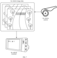
- FIG. 2 is a diagram of a scenario of evaluating a motion state of a traffic tool according to an embodiment of the present disclosure.
- the traffic tool being a driving vehicle is used as an example to describe an evaluation process of a motion state of the traffic tool.
- the driving vehicle may be configured with one or more in-vehicle cameras (for example, a driving recorder camera and a front view sensor camera), and the number of the in-vehicle cameras is not limited in the embodiments of the present disclosure.
- the driving vehicle may be further configured with an in-vehicle terminal 20b, and the in-vehicle camera 20a may acquire in-vehicle image data 20c corresponding to the driving vehicle and transmit the acquired in-vehicle image data 20c to the in-vehicle terminal 20b through a data cable or a wireless local area network.
- the in-vehicle image data 20c (in this case, the in-vehicle image data 20c may be video data) transmitted by the in-vehicle camera 20a is obtained
- the in-vehicle terminal 20b performs framing on the in-vehicle image data 20c to obtain N+1 image frames corresponding to the in-vehicle image data 20c, where N is a positive integer.
- the N+1 image frames may be represented according to a time sequence of the in-vehicle image data 20c as: an image frame T1, an image frame T2, an image frame T3, ..., and an image frame TN+1. Every two adjacent image frames in the N+1 image frames are combined to obtain N image frame groups.
- the image frame T1 and the image frame T2 may form an image frame group 1
- the image frame T2 and the image frame T3 may form an image frame group 2
- an image frame TN and the image frame TN+1 may form an image frame group N.
- any image frame group in the N image frame groups matching feature points between two image frames included in the image frame group may be obtained, Delaunay triangulation networks respectively corresponding to the N image frame groups may be constructed according to the matching feature points corresponding to each image frame group, and the motion state of the driving vehicle may be determined according to the Delaunay triangulation networks respectively corresponding to the N image frame groups.
- Processing on each image frame group of the N image frame groups is the same. The processing on each image frame group is described in detail below by using the image frame group 1 as an example.
- the in-vehicle terminal 20b may extract feature points from the image frame T1 and the image frame T2 included in the image frame group 1. Points whose image grayscale values change drastically or points having a relatively great curvature on an edge of an image (namely, intersection points of two edges) are extracted from the image frame T1 through a feature extraction algorithm, and the extracted image points are determined as a feature point set 20d corresponding to the image frame T1. Similarly, a feature point set 20e may be extracted from the image frame T2 through the same feature extraction algorithm. An image coordinate system may be established in both the image frame T1 and the image frame T2.
- the image coordinate system includes an axis U and an axis V
- a coordinate on the axis U may represent a column of a feature point in the image frame
- a coordinate on the axis V may represent a row of the feature point in the image frame.
- positions of feature points included in the feature point set 20d may be displayed in the image coordinate system of the image frame T1
- positions of feature points included in the feature point set 20e may be displayed in the image coordinate system of the image frame T2.
- the in-vehicle terminal 20b may perform feature point matching on the feature point set 20d and the feature point set 20e through a matching algorithm, determine matching feature points between the feature point set 20d and the feature point set 20e by using a distance between two feature point descriptors (or may be referred to as descriptive features) as a matching principle, to obtain a matching feature point set 20f corresponding to the image frame group 1.
- Image coordinates corresponding to each matching feature point in the matching feature point set 20f may be: an average value of image coordinates on the image frame T1 and the image frame T2.
- a distance threshold may be manually set, and for example, the distance threshold is set to 0.8
- the feature point 1 and the feature point 2 are determined as a matching feature point A between the image frame T1 and the image frame T2.
- image coordinates of the feature point 1 are represented as (u1, v1)
- image coordinates of the feature point 2 are represented as (u2, v2)
- image coordinates of the matching feature point A may be represented as ((u1+u2)/2, (v1+v2)/2).
- a Delaunay triangulation network 20g corresponding to the image frame group 1 may be constructed according to the matching feature point set 20f.
- the Delaunay triangulation network 20g includes connected but non-overlapping triangles, a circumscribed circle of each triangle does not include any matching feature points other than vertexes of the current triangle, and vertexes of each triangle in the Delaunay triangulation network 20g are matching feature points in the matching feature point set 20f.
- the in-vehicle terminal 20b may remove abnormal matching feature points in the matching feature point set 20f according to the Delaunay triangulation network 20g.
- a coordinate change value of a side length AB, a coordinate change value of a side length BC, and a coordinate change value of a side length AC of the triangle may be calculated according to coordinates of the three vertexes in the image frame T1 and the image frame T2 respectively.
- the abnormal matching feature points in the matching feature point set 20f is filtered based on the coordinate change values of the three side lengths in each triangle, to delete the abnormal matching feature points from the matching feature point set 20f.
- the in-vehicle terminal 20b may update the Delaunay triangulation network 20g according to a matching feature point set from which the abnormal matching feature points are deleted, to generate a Delaunay triangulation network 20h corresponding to the image frame group 1. Based on the same operation process, Delaunay triangulation networks respectively corresponding to the N image frame groups may be finally obtained, and the motion state of the driving vehicle is evaluated according to the Delaunay triangulation networks respectively corresponding to the N image frame groups.
- the motion state of the driving vehicle may include a static state, a non-static state, and a linear motion state.
- the motion state of the driving vehicle may be used for assisting a satellite positioning device of the vehicle.
- a Delaunay triangulation network may be constructed according to matching feature points between adjacent image frames, and the motion state of the vehicle may be evaluated based on the Delaunay triangulation network, thereby improving the evaluation accuracy of the motion state of the vehicle.
- FIG. 3 is a schematic flowchart of a method for evaluating a motion state of a traffic tool according to an embodiment of the present disclosure.
- the method for evaluating a motion state of a traffic tool may be performed by a computer device, and the computer device may be a mobile terminal configured for the traffic tool or may be a server exchaing data with the traffic tool.
- the method for evaluating a motion state of a traffic tool may include the following steps S101 to S104.
- step S101 target image data of the traffic tool is obtained, and every two adjacent image frames in the target image data are combined to obtain N image frame groups.
- a photographing device configured for the traffic tool may acquire image data (for example, the in-vehicle image data 20c in the embodiment corresponding to FIG. 2 ) of the traffic tool in a driving process.
- the image data acquired by the photographing device may be transmitted to the computer device.
- the computer device After obtaining the image data acquired by the photographing device, the computer device may determine the acquired image data as target image data.
- the target image data may refer to a series of consecutive image frames (for example, N+1 image frames, and N may be 1, 2, 3, ...) or video data for the traffic tool.
- every two adjacent image frames in the N+1 image frames may be combined to obtain N image frame groups.
- the target image data is video data
- framing may be performed on the target image data to divide the target image data into N+1 image frames, and every two adjacent image frames in the N+1 image frames are combined to obtain N image frame groups.
- the N+1 image frames included in the target image data may be represented according to a time sequence as: an image frame T1, an image frame T2, ..., an image frame TN, and an image frame TN+1.
- the computer device may combine the image frame T1 and the image frame T2 to generate an image frame group 1, combine the image frame T2 and an image frame T3 to generate an image frame group 2, ..., and combine the image frame TN and the image frame TN+1 to generate an image frame group N, thereby obtaining the N image frame groups.
- the traffic tool may be a vehicle on the land, a ship in the sea, an airplane in the air, or a spacecraft.
- the photographing device may serve as a video input device, the photographing device may include a binocular photographing device and a monocular photographing device or may include a wide-angle camera photographing device and a fisheye camera photographing device.
- a type of the photographing device is not limited in the present disclosure.
- step S102 matching feature points between two image frames included in each image frame group of the N image frame groups are obtained.
- the computer device may perform feature point extraction on the target image data, namely, extract feature points from the N+1 image frames respectively.
- Matching feature points (which may be understood as same feature points between two image frames included in each image frame group) respectively corresponding to the N image frame groups may be obtained according to the feature points extracted from each image frame.
- obtaining processes of the matching feature points corresponding to different image frame groups are same. Therefore, the obtaining process of the matching feature points is described by only using any image frame group in the N image frame groups as an example.
- the computer device may obtain any image frame group G i from the N image frame groups.
- the image frame group G i may include an image frame T i and an image frame T i+1 , i is a positive integer less than or equal to N, and namely, a minimum value of i is 1, and a maximum value thereof is N.
- the computer device may obtain a first feature point set in the image frame T i (for example, the feature point set 20d in the embodiment corresponding to FIG. 2 ) and a second feature point set in the image frame T i+1 (for example, the feature point set 20e in the embodiment corresponding to FIG.
- the computer device may, through a feature point extraction algorithm, extract feature points from the image frame T i to obtain the first feature point set, and extract feature points from the image frame T i+1 to obtain the second feature point set, and further determine the matching feature points between the first feature point set and the second feature point set according to a matching algorithm.
- the feature point extraction algorithm may include, but not limited to: a scale-invariant feature transform (SIFT) algorithm, a speeded up robust features (SURF, an improved SIFT algorithm) algorithm, a binary robust invariant scalable keypoints (BRISK, a feature point detection algorithm) algorithm, a binary robust independent elementary features (BRIEF, a binary-coded descriptor) algorithm, a FAST (a feature point detection algorithm) algorithm, and an oriented FAST and rotated BRIEF (ORB, a fast feature point extraction and description algorithm) algorithm.
- the matching algorithm may include, but not limited to: a BruteForce algorithm, a k-nearest neighbors (KNN) algorithm, a fast library for approximate nearest neighbors (FLANN) algorithm.
- the computer device may construct a scale space for the image frame T i and the image frame T i+1 , search the scale space for a first key point position set corresponding to the image frame T i , and search the scale space for a second key point position set corresponding to the image frame T i+1 . Further, the computer device may determine, according to a local gradient corresponding to a first key point position included in the first key point position set, a first descriptive feature corresponding to the first key point position, and obtain the first feature point set of the image frame T i according to the first key point position and the first descriptive feature.
- F' represents the first key point position set corresponding to the image frame T i , namely, F' represents a coordinate set formed by first key point positions of all feature points in the first feature point set;
- f j i represents coordinates of a j th feature point in the first feature point set,
- u j i represents a U-axis coordinate of the j th feature point in an image coordinate system, and
- v j i represents a V-axis coordinate of the j th feature point in the image coordinate system;
- m i represents the number of feature points included in the first feature point set;
- ⁇ i represents a descriptive feature set formed by first descriptive features of all the feature points in the first feature point set, and
- ⁇ 1 i represents a first descriptive feature of a first feature point in the first feature point set.
- the computer device may determine, according to a local gradient corresponding to a second key point position included in the second key point position set, a second descriptive feature corresponding to the second key point position, and obtain the second feature point set of the image frame T i+1 according to the second key point position and the second descriptive feature.
- a representation form of each feature point included in the second feature point set one may refer to the foregoing formula (1).
- F' may be replaced with F i+1
- ⁇ i may be replaced with ⁇ i+1 .
- F i+1 represents a coordinate set formed by second key point positions of all feature points in the second feature point set
- ⁇ i+1 represents a descriptive feature set formed by second descriptive features of all the feature points in the second feature point set.
- the computer device may extract a key point from the image frame (the image frame T i or the image frame T i+1 ), and search the image frame for pixels having a specific feature (in this case, the specific feature is associated with an adopted feature point extraction algorithm), and may further calculate a descriptive feature (may also be referred to as a descriptor) of the key point according to a position of the key point.
- a descriptive feature may also be referred to as a descriptor
- the position of the key point and the corresponding descriptive feature may be referred to as a feature point in the image frame.
- the first feature point set may include one or more feature points
- the second feature point set may include one or more feature points
- the number of feature points included in the first feature point set may be the same as or different from the number of feature points included in the second feature point set.
- Feature point extraction algorithms adopted for the N image frame groups are same.
- the computer device may obtain a first feature point at from the first feature point set and obtain a second feature point b k from the second feature point set, where t is a positive integer less than or equal to the number of the feature points included in the first feature point set, and k is a positive integer less than or equal to the number of the feature points included in the second feature point set.
- the computer device may determine a matching degree between the first feature point at and the second feature point b k according to a first descriptive feature corresponding to the first feature point at and a second descriptive feature corresponding to the second feature point b k ; and determine, in a case that the matching degree is greater than a matching threshold, the first feature point at and the second feature point b k as matching feature points between the image frame T i and the image frame T i+1 .
- matching degrees between the feature point and all the feature points included in the second feature point set need to be calculated respectively, and two feature points whose matching degree is greater than the matching threshold are determined as the matching feature points between the image frame T i and the image frame Ti+i.
- the matching degree may refer to a distance between descriptive features corresponding to two feature points calculated according to the matching algorithm.
- the distance may include, but not limited to, a Mahalanobis distance or a Hamming distance.
- a feature point in the first feature point set matches with at most one feature point in the second feature point set. That is, for any feature point at in the first feature point set, no matching feature point or one matching feature point exists in the second feature point set.
- the first feature point set includes a feature point a1, a feature point a2, and a feature point a3, and the second feature point set includes a feature point b1, a feature point b2, a feature point b3, and a feature point b4.
- Matching degrees between the feature point a1 and the feature point b1, the feature point b2, the feature point b3, and the feature point b4 may be calculated respectively.
- the feature point a1 and the feature point b2 may be determined as matching feature points between the image frame T i and the image frame T i+1 .
- matching degrees between the feature point a2 and the feature point b1, the feature point b2, the feature point b3, and the feature point b4 may be calculated respectively. If no feature point whose matching degree is greater than the matching threshold exists among the feature point b1, the feature point b2, the feature point b3, and the feature point b4, it is determined that no feature point same as the feature point a2 exists in the image frame T i+1 .
- Matching degrees between the feature point a3 and the feature point b1, the feature point b2, the feature point b3, and the feature point b4 are calculated respectively. If the feature point b4 whose matching degree is greater than the matching threshold, the feature point a3 and the feature point b4 may be determined as matching feature points between the image frame T i and the image frame T i+1 , and in this case, two matching feature points exist between the image frame T i and the image frame T i+1 . It may be understood that, matching degrees between feature points in the first feature point set and the second feature point set may be calculated in parallel or in serial.
- the computer device may calculate matching degrees between the feature points in the first feature point set and the feature points in the second feature point set in parallel, and further determine the matching feature points between the image frame T i and the image frame T i+1 according to all calculated matching degrees.
- the computer device may calculate matching degrees between the feature points in the first feature point set and the feature points in the second feature point set in serial, namely, the computer device may stop, in a case that a feature point matching with a feature point at is determined from the second feature point set, calculating matching degrees between the feature point at and other feature points in the second feature point set.
- matching degrees between the feature point a1 and feature points other than the feature point b2 in the second feature point set are unnecessary to be calculated subsequently.
- FIG. 4 is a schematic diagram of feature point extraction performed in two image frames according to an embodiment of the present disclosure.
- the SIFT algorithm is used as an example to describe a feature point extraction process.
- the SIFT algorithm may be used to perform feature point extraction on the image frame T i and the image frame T i+1 that are adjacent to each other, and the feature point extraction process may include two parts: feature point detection and feature point description.
- the SIFT algorithm may be used for detecting and describing local features in an image. According to the algorithm, an extreme point in a space size is searched for, and a position, a scale, and a rotation invariant of the extreme point are extracted.
- a feature point extracted through the SIFT algorithm may be referred to as an SIFT feature, and the SIFT feature is based on points of interest of some local appearance of the image and is not related to a size or rotation of the image.
- the computer device may construct a scale space of the image frame T i , and the scale space may be represented by using a Gaussian pyramid.
- the Gaussian pyramid may be obtained by performing blurring and down-sampling processing on the image frame T i through a Gaussian function. That is, Gaussian blurring of different scales may be performed on the image frame T i , and down-sampling processing is performed on the image frame T i .
- the down-sampling processing may be dot interlaced sampling processing.
- the Gaussian pyramid of the image frame T i introduces a Gaussian filter on the basis of an image pyramid formed through simple down-sampling.
- the image pyramid may include: continuously performing reduced-order sampling processing on the image frame T i to obtain a series of images with different sizes, and constructing the series of images into a tower-shaped model from big to small and from bottom to top.
- the image frame T i may be a first layer of the image pyramid, and a new image obtained through each down-sampling may serve as one layer in the image pyramid (each layer in the image pyramid is an image).
- Gaussian blurring may be performed on each layer of image in the image pyramid by using different parameters, so that each layer of the image pyramid may include multiple Gaussian-blurred images, and the image pyramid may be referred to as a Gaussian pyramid.
- the Gaussian blurring is an image filter, which may calculate a blurring template by using normal distribution (namely, a Gaussian function), and perform convolution operation by using the blurring template and the image frame T i , to blur an image.
- the SIFT algorithm may include steps such as scale space extrema detection, key point positioning, direction determining, and key point description, and the scale space extrema detection, the key point positioning, and the direction determining may be referred to as a feature point detection process.
- the scale space extrema detection may include searching for image positions in all scales, namely, identifying potential points of interest invariant to scales and rotation through a Gaussian differentiation function, where there may be multiple points of interest in this case.
- the key point positioning may include determining a position and a scale of a key point in the Gaussian pyramid from the points of interest through a finely fitted model, where selection of the key point depends on the stability of the points of the interest.
- the direction determining may include allocating one or more directions to a position of each feature point based on a local gradient direction of an image in the image frame T i , so that the image frame T i may be operated by transforming the direction, the scale, and the position of the key point.
- the key point description may include measuring a local gradient of an image in a selected scale in the Gaussian pyramid in a neighbourhood of each key point. The gradient may be transformed into a vector representation, and the vector representation may allow relatively great local shape deformation and illumination changes.
- the first feature point set corresponding to the image frame T i is obtained.
- the second feature point set corresponding to the image frame T i+1 is obtained based on the same processing procedure.
- the computer device may perform feature point matching on the first feature point set and the second feature point set to obtain the matching feature points between the image frame T i and the image frame Ti+i.
- FIG. 5 is a schematic diagram of feature point matching performed between two image frames according to an embodiment of the present disclosure.
- the KNN algorithm is used as an example to describe the feature point matching process between the first feature point set and the second feature point set.
- an image coordinate system of the image frame T i and an image coordinate system of the image frame T i+1 are established, position coordinates of the feature points included in the first feature point set are represented in the image coordinate system of the image frame T i , and position coordinates of the feature points included in the second feature point set are represented in the image coordinate system of the image frame T i+1 .
- the computer device may calculate distances between any feature point at in the first feature point set and all the feature points included in the second feature point set respectively (the distance may refer to a distance such as a Mahalanobis distance or a Hamming distance between descriptive features corresponding to different feature points, and a smaller distance between two feature points indicates a larger matching degree between the two feature points), may further rank the distances in ascending order, select K feature points with smallest distance, determine appearance frequencies of the feature point at corresponding to the first K feature points in the second feature point set, and determines a feature point with the highest appearance frequency in the first K feature points as a feature point same as the feature point at. As shown in FIG.
- a feature point a1 in the first feature point set and a feature point b1 in the second feature point set are matching feature points
- a feature point a2 in the first feature point set and a feature point b2 in the second feature point set are matching feature points
- a feature point a3 in the first feature point set and a feature point b3 in the second feature point set are matching feature points
- a feature point a4 in the first feature point set and a feature point b4 in the second feature point set are matching feature points.
- step S103 target mesh plane graphs respectively corresponding to the N image frame groups are constructed according to the matching feature points corresponding to each image frame group.
- the computer device may construct target mesh plane graphs respectively corresponding to the N image frame groups according to the matching feature points respectively corresponding to each image frame group. That is, one image frame group may correspond to one target mesh plane graph, each target mesh plane graph may include multiple connected but non-overlapping polygons, a circumscribed circle of each polygon does not include any matching feature point, and vertexes of each polygon may be the matching feature points corresponding to each image frame group.
- the target mesh plane graph may be a Delaunay triangulation network
- the polygons in the target mesh plane graph may all be triangles
- the computer device may construct a corresponding Delaunay triangulation network for each image frame group according to the empty circumscribed circle property and the largest minimum angle property of the Delaunay triangulation network.
- a method for constructing a Delaunay triangulation network may include, but not limited to: a segmentation and merging algorithm, a point-by-point insertion algorithm, and a recursive growth algorithm.
- a segmentation and merging algorithm matching feature points corresponding to a single image frame group is segmented into point subsets that is easy to triangulation (for example, each point subset may include 3 or 4 matching feature points), triangulation processing is performed on each point subset, a triangulated triangulation network is optimized into a Delaunay triangulation network through a local optimization procedure (LOP) algorithm, and the Delaunay triangulation network of each point subset is merged to form a final Delaunay triangulation network.
- LOP local optimization procedure
- initial triangles of all matching feature points in a single image frame group are constructed, the initial triangles are stored in a triangle linked list, and the matching feature points in the image frame group are inersted into the triangle linked list sequentially, so that a Delaunay triangulation network corresponding to the image frame group is formed after all the matching feature points in the image frame group are inserted into the triangle linked list.
- any matching feature point 1 is selected from matching feature points corresponding to a single image frame group, a matching feature point 2 that is closest to the matching feature point 1 is searched for, the matching feature point 1 and the matching feature point 2 are connected as an initial baseline 1-2, a matching feature point 3 is searched for on one side (for example, a right side or a left side) of the initial baseline 1-2 by adopting a Delaunay principle to form a first Delaunay triangle, two new sides (a side length 2-3 and a side length 1-3) of the Delaunay triangle are used as a new initial baseline, and the foregoing steps are repeated until all the matching feature points in the image frame group are processed, to obtain a Delaunay triangulation network corresponding to the image frame group.
- step S104 the motion state of the traffic tool is determined according to the target mesh plane graphs respectively corresponding to the N image frame groups.
- the computer device may determine the motion state of the traffic tool according to an average coordinate change value of each triangle in the Delaunay triangulation network, and the motion state of the traffic tool may be a static state or a non-static state; or determine the motion state of the traffic tool according to direction change values respectively corresponding to three sides included in each triangle in the Delaunay triangulation network, and the motion state of the traffic tool may be a linear motion state or a non-linear motion state.
- the motion state of the traffic tool may be used for providing an assistance foundation for positioning and navigation of the traffic tool.
- positioning information of the traffic tool may be determined according to a positioning and navigation system (for example, satellite positioning) in a case that the motion state of the traffic tool is the static state; and in a case that the motion state of the traffic tool is the linear motion state, a motion direction of the traffic tool may be determined according to the linear motion state, and the positioning information of the traffic tool may be determined according to the motion direction and the positioning and navigation system.
- a positioning and navigation system for example, satellite positioning
- a motion direction of the traffic tool may be determined according to the linear motion state
- the positioning information of the traffic tool may be determined according to the motion direction and the positioning and navigation system.
- the motion state of the traffic tool may effectively assist the positioning and navigation system, and may further improve the positioning precision of a terminal configured for the traffic tool.
- an accurate motion state may effectively assist lane-level positioning and navigation.
- the target image data corresponding to the traffic tool may be obtained, the matching feature points between two adjacent image frames are extracted, the target mesh plane graph corresponding to the two adjacent image frames is constructed according to the matching feature points between the two adjacent image frames, and the motion state of the traffic tool is accurately evaluated based on the target mesh plane graph, thereby improving the evaluation accuracy of the motion state of the traffic tool.
- the motion state of the traffic tool can effectively assist the positioning and navigation system, and can further improve the positioning precision of a terminal configured for the traffic tool.
- FIG. 6 is a schematic flowchart of obtaining a target mesh plane graph according to an embodiment of the present disclosure.
- step S101 to step S103 in the embodiment corresponding to FIG. 3 are described in more detail by using an example in which the target mesh plane graph is a Delaunay triangulation network.
- the target mesh plane graph may be obtained through the following step S201 to step S207.
- step S201 in-vehicle image data is obtained through a connection line.
- a computer device may obtain original image data of a traffic tool acquired by a photographing device.
- the computer device may be an in-vehicle terminal
- the photographing device may be a front-facing camera or a driving recorder camera configured for the driving vehicle
- the original image data may be in-vehicle image data.
- the in-vehicle image data may refer to image data acquired by the photographing device within a period of time.
- the in-vehicle image data may refer to N+1 image frames acquired by the photographing device within 1 second.
- the in-vehicle terminal 30e may obtain in-vehicle image data acquired by the in-vehicle camera 30a through a universal serial bus (USB) or a high definition multimedia interface (HDMI) connection line.
- the in-vehicle image data may be multiple image frames in an RGB (a color standard, where R represents color, G represents green, and B represents blue) format, such as an image frame 30b, an image frame 30c, and an image frame 30d.
- RGB a color standard, where R represents color, G represents green, and B represents blue
- step S202 denoising processing is performed on the in-vehicle image data based on a Wiener filter, and distortion removing processing is performed on an image according to parameters of the in-vehicle camera to obtain a corrected image.
- the computer device may perform denoising processing on the in-vehicle image data to obtain denoised image data, and may further perform distortion removing processing on the denoised image data according to device parameters of the photographing device to obtain target image data of the traffic tool.
- the target image data is divided into N+1 image frames, every two adjacent image frames in the N+1 image frames are combined to obtain N image frame groups. In this case, image frames included in the N image frame groups are all corrected images obtained through denoising processing and distortion removing processing.
- the denoising processing of the in-vehicle image data may be implemented through a Wiener filter (which may be referred to as a least square filter), noise and interference may be filtered from the in-vehicle image data through the Wiener filter.
- the Wiener filter may refer to a linear filter using a least square as an optimal principle, and in a specific constraint condition, a square of a difference between an output and a desired output of the Wiener filter is minimized, which may be finally converted into a problem of calculating a solution to a Toeplitz equation through mathematical calculation.
- the device parameters of the photographing device may be parameters of the in-vehicle camera, and the distortion removing processing on the in-vehicle image data may be implemented based on the parameters of the in-vehicle camera.
- the denoising processing and the distortion removing processing belong to pre-processing of the in-vehicle image data.
- the pre-processing of the in-vehicle image data may further include deblurring processing and smoothing processing.
- a method adopted in the pre-processing is not limited in the embodiments of the present disclosure.
- the original image data (namely, the in-vehicle image data obtained from the in-vehicle camera through the USB or HDMI connection line) obtained by the computer device may include N+1 image frames, which are respectively an image frame T1, an image frame T2, ..., and an image frame TN+1. Due to factors such as the photographing device and data transmission, the N+1 image frames included in the original image data may have distortion or have noise data, thus the computer device may perform denoising processing on the N+1 image frames included in the original image data by using the Wiener filter.
- distortion removing processing may be performed on the N+1 image frames included in the original image data according to the parameters of the in-vehicle camera.
- the N+1 image frames subjected to denoising processing and distortion removing processing are determined as the target image data, and N image frame groups may be obtained by combining every two adjacent image frames in the N+1 image frames in the target image data.
- step S203 image feature points of an image frame T i and an image frame T i+1 are extracted according to an image feature point extraction algorithm.
- step S204 matching feature points between the image frame T i and the image frame T i+1 are matched through a matching algorithm.
- Every image frame group of the N image frame groups includes two adjacent image frames, and the two adjacent image frames are corrected image frames subjected to denoising processing and distortion removing processing.
- a generation process of a target mesh plane graph corresponding to different image frame groups is similar.
- the generation process of the target mesh plane graph is described by using any image frame group G i in the N image frame groups as an example.
- the image frame group G i may include a corrected image frame T i and a corrected image frame T i+1 .
- the generation process of the target mesh plane graph may include a process of extracting feature points of the image frame T i and the image frame T i+1 , a process of determining matching feature points between the image frame T i and the image frame T i+1 , and a process of constructing a Delaunay triangulation network corresponding to the image frame group G i . Therefore, for a specific implementation of step S203 and step S204, one may refer to step S102 in the embodiment corresponding to FIG. 3 , and details are not described herein again.
- step S205 Delaunay triangulation processing is performed on all matching feature points between the image frame T i and the image frame Ti+i.
- the computer device may determine, according to image coordinate information of each matching feature point of the q matching feature points in the image frame T i and the image frame T i+1 , matching coordinate information respectively corresponding to the q matching feature points.
- the matching coordinate information is an image coordinate average value in the image frame T i and the image frame T i+1 , i is a positive integer less than or equal to N, and q is a positive integer.
- the computer device may obtain an initial polygon linked list associated with the q matching feature points according to the matching coordinate information respectively corresponding to the q matching feature points.
- an associated polygon matching with the matching feature point c r is obtained from the initial polygon linked list.
- a circumscribed circle of the associated polygon may include the matching feature point c r , r is a positive integer less than or equal to q, namely, a minimum value of r is 1, and a maximum value thereof is q.
- the computer device may delete a common side of the associated polygon, connect the matching feature point c r to all vertexes of the associated polygon to generate a candidate polygon corresponding to the matching feature point c r , may further convert the candidate polygon into a target polygon corresponding to the matching feature point c r , and add the target polygon to the initial polygon linked list.
- the target polygon meets the empty circumscribed circle property in this case.
- the initial polygon linked list including the target polygons corresponding to the q matching feature points is determined as a target polygon linked list.
- a mesh plane graph corresponding to the image frame group G i is generated according to the target polygon linked list.
- the mesh plane graph in this case may be referred to as a candidate mesh plane graph.
- Delaunay triangulation network processing may be performed on the q matching feature points between the image frame T i and the image frame T i+1 based on a Bowyer-Watson algorithm (a triangulation network generation algorithm), and a process thereof may include: 1. traversing the q matching feature points, constructing an initial triangle including the q matching feature points according to the matching coordinate information respectively corresponding to the q matching feature points, and storing the initial triangle into an initial triangle linked list (namely, the initial polygon linked list); 2.
- a Bowyer-Watson algorithm a triangulation network generation algorithm
- each matching feature point in the q matching feature points sequentially (for example, the matching feature point c r in the q matching feature points), searching for an affected triangle (namely, the associated polygon) whose circumscribed circle includes the matching feature point c r from the initial triangle linked list, deleting a common side of the affected triangle, and connecting the matching feature point c r to all vertexes of the affected triangle to obtain a candidate triangle (namely, the foregoing candidate polygon) corresponding to the matching feature point c r , so as to complete insertion of the matching feature point c r in the initial triangle linked list; 3.
- the initial triangle linked list in this case may be referred to as a target triangle linked list (namely, the target polygon linked list), and the target triangle linked list may be determined as the Delaunay triangulation network corresponding to the image frame group G i .
- FIG. 9 is a schematic structural diagram of constructing a mesh plane graph according to an embodiment of the present disclosure.
- the 7 matching feature points are respectively represented as a matching feature point A, a matching feature point B, a matching feature point C, a matching feature point D, a matching feature point E, a matching feature point F, and a matching feature point P.
- the triangle linked list may include a triangle ABD, a triangle ABC, a triangle BCE, a triangle BEF, and a triangle BDF.
- the computer device may search the triangle linked list for a triangle whose circumscribed circle includes the matching feature point P.
- a circumscribed circle 1 of the triangle ABD and a circumscribed circle 2 of the triangle ABC both includes the matching feature point P, and the triangle ABD and the triangle ABC may be referred to as affected triangles of the matching feature point P.
- the computer device may delete a common side AB of the triangle ABD and the triangle ABC, connect the matching feature point P to all vertexes of the triangle ABD and the triangle ABC to form new triangles. That is, the matching feature point P is connected to the matching feature point A, the matching feature point P is connected to the matching feature point B, the matching feature point P is connected to the matching feature point C, and the matching feature point P is connected to the matching feature point D, to form a new triangle ADP, a new triangle ACP, a new triangle BCP, and a new triangle BDP.
- the triangle ADP, the triangle ACP, the triangle BCP, and the triangle BDP are stored into the triangle linked list, and the Delaunay triangulation network corresponding to the image frame group G i is generated according to the triangle linked list.
- step S206 abnormal matching feature points are removed based on an established Delaunay triangulation network.
- the matching feature points between the image frame T i and the image frame T i+1 may include abnormal matching feature points, so the computer device may remove the abnormal matching feature points from the Delaunay triangulation network generated according to step S205.
- the computer device may determine the Delaunay triangulation network generated through step S205 as a candidate mesh plane graph, and obtain any polygon D j from the candidate mesh plane graph, where j is a positive integer less than or equal to the number of polygons included in the candidate mesh plane graph. Further, the computer device may obtain first vertex coordinates of matching feature points corresponding to the polygon D j in the image frame T i and second vertex coordinates of the matching feature points corresponding to the polygon D j in the image frame T i+1 .
- a coordinate change value corresponding to each side length included in the polygon D j is determined according to the first vertex coordinates and the second vertex coordinates; a side length whose coordinate change value is less than a change threshold is determined as a target side length, normal verification parameters (the normal verification parameter may be a counter value) corresponding to matching feature points on two ends of the target side length are accumulated to obtain a total value of a normal verification parameter corresponding to each of the matching feature points of the polygon D j ; and a matching feature point whose total value of the normal verification parameter is greater than a parameter threshold is determined as a normal matching feature point, and a matching feature point other than the normal matching feature point may be referred to as an abnormal matching feature point. Specifically, matching feature points other than normal matching feature points in the q matching feature points may be deleted.
- the first vertex coordinates may refer to coordinates of the three vertexes of the triangle ⁇ D j in the image frame T i , u D j , 1 i , u D j , 2 i , and u D j , 3 i may represent coordinates of the three vertexes of the triangle ⁇ D j on the axis U in the image frame T i respectively, and v D j , 1 i , v D j , 2 i , and v D j , 3 i may represent coordinates of the three vertexes of the triangle ⁇ D j on the axis V in the image frame T i respectively.
- Second vertex coordinates of the three vertexes of the triangle ⁇ D j in the image frame T i+1 may be shown by the following formula (4): u D j , 1 i + 1 v D j , 1 i + 1 u D j , 2 i + 1 v D j , 2 i + 1 u D j , 3 i + 1 v D j , 3 i + 1
- the second vertex coordinates may refer to coordinates of the three vertexes of the triangle ⁇ D j in the image frame T i+1 , u D j , 1 i + 1 , u D j , 2 i + 1 , and u D j , 3 i + 1 may represent coordinates of the three vertexes of the triangle ⁇ D j on the axis U in the image frame T i +1 respectively, and v D j , 1 i + 1 , v D j , 2 i + 1 , and v D j , 3 i + 1 may represent coordinates of the three vertexes of the triangle ⁇ D j on the axis V in the image frame T i+1 respectively.
- a counter may be allocated to each matching feature point in the q matching feature points. If the coordinate change value dAB of the side length AB in formula (5) is less than a change threshold (the change threshold may be preset), the side length AB may be determined as a target side length, and counters of two vertexes (namely, the matching feature point A and the matching feature point B) of the target side length AB is increased by 1; and if the coordinate change value dAB is greater than or equal to the change threshold, no processing may be performed on the counters of the matching feature point A and the matching feature point B.
- a change threshold the change threshold may be preset
- the side length BC may be determined as a target side length, and counters of two vertexes (namely, the matching feature point B and the matching feature point C) of the target side length BC is increased by 1; and if the coordinate change value dBC is greater than or equal to the change threshold, no processing may be performed on the counters of the matching feature point B and the matching feature point C.
- the side length AC may be determined as a target side length, and counters of two vertexes (namely, the matching feature point A and the matching feature point C) of the target side length AC is increased by 1; and if the coordinate change value dAC is greater than or equal to the change threshold, no processing may be performed on the counters of the matching feature point A and the matching feature point C.
- the computer device may circularly process each triangle in the candidate mesh plane graph according to formula (5) to formula (7) until the m triangles are all processed, to obtain total values of counters (namely, the total values of the normal verification parameters) respectively corresponding to the q matching feature points. If a total value of the counter of a matching feature point is greater than a parameter threshold (the parameter threshold may be preset, and for example, the parameter threshold is 4), the matching feature point may be determined as a normal matching feature point, and the matching feature point may be reserved; and if a total value of the counter of a matching feature point is less than or equal to the parameter threshold (for example, the parameter threshold is 4), the matching feature point may be determined as an abnormal matching feature point, and the abnormal matching feature point may be deleted.
- a parameter threshold may be preset, and for example, the parameter threshold is 4
- the matching feature point may be determined as a normal matching feature point, and the matching feature point may be reserved; and if a total value of the counter of a matching feature point is less than or equal
- step S207 the Delaunay triangulation network from which abnormal matching feature points are removed is obtained.
- the computer device may update, according to normal matching feature points, the candidate mesh plane graph to a target mesh plane graph corresponding to the image frame group G i , for example, obtain a Delaunay triangulation network from which abnormal matching feature points are removed according to the normal matching feature points. That is, the computer device may delete triangles including the abnormal matching feature points from the candidate mesh plane graph, to form a final Delaunay triangulation network corresponding to the image frame group G i .
- the computer device may re-construct, according to the Delaunay triangulation processing described in step S205, a Delaunay triangulation network according to the normal matching feature points.
- the Delaunay triangulation network including the normal matching feature points may be referred to as the target mesh plane graph.
- Target Delaunay triangulation networks respectively corresponding to the N image frame groups may be obtained based on step S203 to step S207.
- in-vehicle image data corresponding to a driving vehicle is obtained, matching feature points between two adjacent image frames are extracted, a Delaunay triangulation network corresponding to the two adjacent image frames is constructed by using the matching feature points between the two adjacent image frames, and abnormal matching feature points are removed based on the Delaunay triangulation network. Therefore, the effectiveness of the matching feature points can be improved, and a motion state of the driving vehicle is determined based on the Delaunay triangulation network, thereby improving the evaluation accuracy of the motion state of the vehicle.
- FIG. 10 is a schematic flowchart of a method for evaluating a motion state of a traffic tool according to an embodiment of the present disclosure.
- the method for evaluating a motion state of a traffic tool may be performed by a computer device, and the computer device may be a mobile terminal configured for the traffic tool.
- the method for evaluating a motion state of a traffic tool may include the following steps: S301 ti S306.
- step S301 in-vehicle image data is pre-processed (eliminate image noise and distortion).
- step S302 image feature points of the in-vehicle image data are extracted.
- step S303 feature points of adjacent image frames are matched.
- step S304 a Delaunay triangulation network is established by using matching feature points.
- step S305 abnormal matching feature points are removed based on the Delaunay triangulation network.
- step S301 to step S305 an implementation procedure of the method for evaluating a motion state of a traffic tool is described by using an example in which the traffic tool is a driving vehicle and a target mesh plane graph is a Delaunay triangulation network.
- a target mesh plane graph is a Delaunay triangulation network.
- step S306 a motion state of a vehicle is determined based on the Delaunay triangulation network.
- the computer device may determine a motion state of a driving vehicle according to triangles included in the Delaunay triangulation network, and a process of determining a motion state of a vehicle (or a process of evaluating a motion state of a vehicle) is described in detail based on FIG. 11 to FIG. 14 .
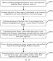
- FIG. 11 and FIG. 12 describe a process of determining a static motion state
- FIG. 13 and FIG. 14 describe a process of determining a linear motion state of the vehicle.
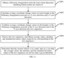
- FIG. 11 is a schematic flowchart of determining a static state of a traffic tool based on a target mesh plane graph according to an embodiment of the present disclosure.
- the determining process of a static state of a traffic tool may include step S401 to step S405.
- step S401 a Delaunay triangulation network from which abnormal matching feature points are removed is obtained.
- the computer device may obtain an image frame group G i in N image frame groups, and further obtain a target mesh plane graph H; corresponding to the image frame group G i .
- the target mesh plane graph H i includes M polygons, M is a positive integer, and i is a positive integer less than or equal to N.
- the target mesh plane graph H may refer to a Delaunay triangulation network from which abnormal matching feature points are removed and corresponding to the image frame group G i (for ease of description, the "Delaunay triangulation network from which abnormal matching feature points are removed and corresponding to the image frame group G i " is referred to as a "Delaunay triangulation network corresponding to the image frame group G i ").
- the image frame group G i may include an image frame T i and an image frame T i+1
- the Delaunay triangulation network corresponding to the image frame group G i may include M triangles, and a minimum value of i is 1 and a maximum value thereof is N.
- the determining process of a static state of a vehicle is described by using the Delaunay triangulation network corresponding to the image frame group G i as an example.
- step S402 average coordinate change values of each triangle in the Delaunay triangulation network in a U-axis direction and a V-axis direction are calculated.
- the computer device may obtain image coordinate information of all matching feature points included in the Delaunay triangulation network in the image frame T i and the image frame T i+1 respectively, that is, image coordinate information of vertexes of each triangle in the Delaunay triangulation network in the image frame T i and the image frame Ti+i. Further, the computer device may obtain average coordinate change values respectively corresponding to the M triangles in the Delaunay triangulation network (namely, the polygon in this embodiment of this application is a triangle) according to the image coordinate information of the vertexes of each triangle in the image frame T i and the image frame Ti+i.
- the average coordinate change value herein may include average coordinate change values in a U-axis direction and in a V-axis direction in an image coordinate system.
- ⁇ representd the Delaunay triangulation network (namely, the Delaunay triangulation network from which abnormal matching feature points are removed) corresponding to the image frame group G i
- ⁇ D s 1 represents a first triangle in the Delaunay triangulation network
- ⁇ D sM represents an M th triangle in the Delaunay triangulation network.
- Image coordinate information of three vertexes (one vertex corresponds to one normal matching feature point) of any triangle ⁇ Ds j , j 1,2, ...
- M in the Delaunay triangulation network in the image frame T i may be shown by the following formula (9): u D sj , 1 i v D sj , 1 i u D sj , 2 i v D sj , 2 i u D sj , 3 i v D sj , 3 i u D sj , 1 i , u D sj , 2 i , and u D sj , 3 i represent coordinates of the three vertexes of the triangle ⁇ Ds j on the axis U in the image frame T i respectively, and v D sj , 1 i , v D sj , 2 i , and v D sj , 3 i represent coordinates of the three vertexes of the triangle ⁇ Ds j on the axis V in the image frame T i respectively.
- Image coordinate information of the three vertexes of the triangle ⁇ Ds j in the image frame Ti+i may be shown by the following formula (10): u D sj , 1 i + 1 v D sj , 1 i + 1 u D sj , 2 i + 1 v D sj , 2 i + 1 u D sj , 3 i + 1 v D sj , 3 i + 1 u D sj , 1 i + 1 , u D sj , 2 i + 1 , and u D sj , 3 i + 1 represent coordinates of the three vertexes of the triangle ⁇ Ds j on the axis U in the image frame T i +1 respectively, and v D sj , 1 i + 1 , v D sj , 1 i + 1 represent coordinates of the three vertexes of the triangle ⁇ Ds j on the axis U in the image frame T
- d v , sj v D sj , 1 i + 1 ⁇ v D sj , 1 i + v D sj , 2 i + 1 ⁇ v D sj , 2 i + v D sj , 3 i + 1 ⁇ v D sj , 3 i 3
- step S403 average coordinate change values of all triangles in the Delaunay triangulation network in the U-axis direction and in the V-axis direction are combined to form two sequences.
- step S404 the two sequences are processed, to obtain average values, medians, and standard deviation values respectively corresponding to the two sequences.
- the computer device may process a sequence ⁇ u and a sequence ⁇ v to obtain statistical values associated with the Delaunay triangulation network.
- the statistical values may include an average value, a median, and a standard deviation value calculated according to the sequence ⁇ u and an average value, a median, and a standard deviation value calculated according to the sequence ⁇ v .
- the average values corresponding to the sequence ⁇ u and the sequence ⁇ v may be referred to as coordinate average values
- the medians corresponding to the sequence ⁇ u and the sequence ⁇ v may be referred to as coordinate medians
- the standard deviation values corresponding to the sequence ⁇ u and the sequence ⁇ v may be referred to as coordinate standard deviation values.
- the statistical values one may refer to the description in the following embodiment corresponding to FIG. 12 .
- step S405 the current vehicle is determined to be in a static state in a case that the average values, the medians, and the standard deviation values of the two sequences are all less than a given threshold.
- a target mesh plane graph may be constructed for each image frame group, namely, N Delaunay triangulation networks may be obtained according to normal matching feature points respectively corresponding to the N image frame groups, one Delaunay triangulation network may correspond to one sequence ⁇ u and one sequence ⁇ v .
- the first threshold herein may include a first average value threshold, a first median threshold, and a standard deviation value threshold, and the first average value threshold, the first median threshold, and the standard deviation value threshold may be different preset values.
- in-vehicle image data of a traffic tool is obtained, matching feature points between two adjacent image frames are extracted, a Delaunay triangulation network corresponding to the two adjacent image frames is constructed by using the matching feature points between the two adjacent image frames, and abnormal matching feature points are removed based on the Delaunay triangulation network. Therefore, the effectiveness of the matching feature points can be improved, and a motion state of the traffic tool is determined based on the Delaunay triangulation network, thereby not only improving the evaluation accuracy of the motion state of the traffic tool, but also simplifying the evaluation procedure of the static state of the traffic tool, and thus improving the evaluation efficiency of the motion state of the traffic tool.
- FIG. 12 is a schematic flowchart of determining a static state of a traffic tool based on a target mesh plane graph according to an embodiment of the present disclosure.
- the process of evaluating the static state of the traffic tool according to the target mesh plane graphs respectively corresponding to the N image frame groups may be performed as follows.
- the computer device may obtain a target mesh plane graph H; corresponding to an image frame group G i of the N image frame groups.
- the target mesh plane graph H i may include M polygons.
- the computer device may obtain average coordinate change values respectively corresponding to the M polygons, rank the average coordinate change values respectively corresponding to the M polygons, determine the ranked average coordinate change values as a first coordinate sequence of the target mesh plane graph H i , and determine statistical values associated with the target mesh plane graph H; according to the first coordinate sequence; and determine the motion state of the traffic tool as a static state in a case that statistical values respectively associated with N target mesh plane graphs are all less than a first threshold.
- the first coordinate sequence may include a sequence of the target mesh plane graph H; in the U-axis direction (for example, a sequence obtained by ranking average coordinate change values included in a first sequence below in an ascending order) and a sequence of the target mesh plane graph H; in the V-axis direction (for example, a sequence obtained by ranking average coordinate change values included in a second sequence below in an ascending order).
- the statistical values may include a coordinate average value, a coordinate median, and a coordinate standard deviation value.
- the coordinate average value may include an average value corresponding to the sequence in the U-axis direction and an average value corresponding to the sequence in the V-axis direction
- the coordinate median may include a median corresponding to the sequence in the U-axis direction and a median corresponding to the sequence in the V-axis direction
- the coordinate standard deviation value may include a standard deviation value corresponding to the sequence in the U-axis direction and a standard deviation value corresponding to the sequence in the V-axis direction.
- the first threshold may include a first average value threshold, a first median threshold, and a standard deviation value threshold which are different from each other.
- a determining process of statistical values thereof may be performed as follows.
- the computer device may update the first coordinate sequence according to a median corresponding to the first coordinate sequence and the average coordinate change values included in the first coordinate sequence to obtain a second coordinate sequence. Further, the computer device may determine an effective value range of element values included in the second coordinate sequence according to a lower quartile corresponding to the second coordinate sequence and an upper quartile corresponding to the second coordinate sequence, and determine element values falling within the effective value range in the second coordinate sequence as a third coordinate sequence.
- the computer device may obtain an initial tagged array corresponding to the first coordinate sequence, and update the initial tagged array according to a lower quartile corresponding to the first coordinate sequence, an upper quartile corresponding to the first coordinate sequence, and a median corresponding to the third coordinate sequence to obtain a target tagged array. Further, the computer device may filter the average coordinate change values included in the first coordinate sequence according to a non-zero element in the target tagged array to update the first coordinate sequence to a fourth coordinate sequence, to obtain a coordinate average value, a coordinate median, and a coordinate standard deviation value corresponding to the fourth coordinate sequence.
- the determining process (or may be referred to as an evaluation process) of a static state of a traffic tool may include step S1201 to step S1223.
- step S1201 a Delaunay triangulation network from which abnormal matching feature points are removed is obtained.
- step S1202 average coordinate change values of each triangle in the Delaunay triangulation network in a U-axis direction and a V-axis direction are calculated.
- step S1201 and step S1202 For a specific implementation of step S1201 and step S1202, one may refer to step S401 and step S402 in the embodiment corresponding to FIG. 11 , and details are not described herein again.
- step S1203 the average coordinate change value of each triangle in the U-axis direction froms a first sequence.
- the computer device may form a sequence of the Delaunay triangulation network in the U-axis direction according to average coordinate change values of M triangles in the Delaunay triangulation network in the U-axis direction.
- the sequence may be referred to as a first sequence, and the first sequence is expressed as the foregoing formula (13).
- step S1204 elements of the first sequence are ranked in an ascending order.
- the first sequence may include the average coordinate change values of the M triangles of the Delaunay triangulation network in the U-axis direction respectively, and a first coordinate sequence in the U-axis direction may be obtained by ranking the average coordinate change values included in the first sequence in an ascending order.
- step S1205 a first tagged array is initialized.
- the initial tagged array mask[M] may be an array including M elements, namely, the number of elements in the initial tagged array mask[M] is the same as the number of triangles included in the Delaunay triangulation network.
- step S1206 an upper quartile, a lower quartile, and a median of the ranked first sequence are calcualted.
- the ranked first sequence may be referred to as the first coordinate sequence ⁇ u sort of the M triangles in the U-axis direction
- the computer device may calculate an upper quartile, a lower quartile, and a median of the first coordinate sequence ⁇ u sort in the U-axis direction.
- the upper quartile may refer to an average coordinate change value at a 75% position in the first coordinate sequence ⁇ u sort in the U-axis direction
- the lower quartile may refer to an average coordinate change value at a 25% position in the first coordinate sequence ⁇ u sort in the U-axis direction
- the median may refer to an average coordinate change value at a 50% position in the first coordinate sequence ⁇ u sort in the U-axis direction.
- Int in formula (17) represents rounding operation
- Dec represents a decimal calculation operation
- step S1207 the first tagged array is updated.
- the gross error may refer to a large error, which is an error greater than a maximum error that is likely to occur in a normal observation condition
- step S1208 the ranked first sequence is processed to obtain a new sequence.
- the computer device may update the first coordinate sequence ⁇ u sort in the U-axis direction according to the median M 1/2 of the first coordinate sequence ⁇ u sort in the U-axis direction to obtain a new sequence.
- the new sequence may be referred to as a second coordinate sequence ⁇ ⁇ u sort in the U-axis direction
- step S1209 an upper quartile, a lower quartile, and a median of the new sequence are calculated.
- the computer device may calculate a lower quartile, an upper quartile, and a median corresponding to the second coordinate sequence ⁇ ⁇ u sort in the U-axis direction.
- a calculation process thereof is similar to the calculation process of the lower quartile M 1/4 , the upper quartile M 3/4 , and the median M 2/4 of the first coordinate sequence ⁇ u sort in the U-axis direction, and details are not described herein again.
- the lower quartile of the second coordinate sequence ⁇ ⁇ u sort in the U-axis direction may be represented as M 1/4
- the upper quartile of the second coordinate sequence ⁇ ⁇ u sort in the U-axis direction may be represented as M 3/4
- the median of the second coordinate sequence ⁇ ⁇ u sort in the U-axis direction may be represented as M 2/4 .
- the computer device may determine an effective value range of element values included in the second coordinate sequence ⁇ ⁇ u sort in the U-axis direction according to the lower quartile M 1/4 and the upper quartile M 3/4 corresponding to the second coordinate sequence ⁇ ⁇ u sort in the U-axis direction, and determine element values falling within the effective value range in the second coordinate sequence ⁇ ⁇ u sort in the U-axis direction as a third coordinate sequence ⁇ ⁇ ⁇ u sort in the U-axis direction.
- the computer device may further calculate a median M ⁇ ⁇ 2 / 4 corresponding to the third coordinate sequence ⁇ ⁇ ⁇ u sort in the U-axis direction, and a calculation process of the median M ⁇ ⁇ 2 / 4 is similar to the calculation process of the median M 2/4 of the first coordinate sequence ⁇ u sort in the U-axis direction.
- step S1210 the first tagged array is updated.
- This operation is a process of updating and processing the updated first tagged array again, and an updated first tagged array may be obtained after this operation.
- step S1211 a gross error in the first sequence is removed according to the first tagged array.
- step S1212 an average value, a median, and a standard deviation value of the first sequence from which the gross error is removed are calculated.
- the computer device may obtain an average value Avg u , a median Med u , and a standard deviation value STD u of the fourth coordinate sequence ⁇ u in the U-axis direction according to element values included in the fourth coordinate sequence ⁇ u in the U-axis direction.
- the average value Avg u , the median Med u , and the standard deviation value STD u may be referred to as statistical values of the Delaunay triangulation network in the U-axis direction.
- step S1213 the average coordinate change value of each triangle in the V-axis direction froms a second sequence.
- the computer device may form a sequence of the Delaunay triangulation network in the V-axis direction according to average coordinate change values of the M triangles in the Delaunay triangulation network in the V-axis direction.
- the sequence may be referred to as a second sequence, and the second sequence is expressed as the foregoing formula (14).
- step S1214 elements of the second sequence are ranked in an ascending order.
- the second sequence may include the average coordinate change values of the M triangles of the Delaunay triangulation network in the V-axis direction respectively, and a first coordinate sequence in the V-axis direction may be obtained by ranking the average coordinate change values included in the second sequence in an ascending order.
- step S1215 a second tagged array is initialized.
- An initial tagged array corresponding to the first coordinate sequence in the V-axis direction is the same as the initial tagged array corresponding to the first coordinate sequence in the U-axis direction, namely, an initialized second tagged array is the same as the initialized first tagged array.
- the initialized second tagged array may be shown by the foregoing formula (16), and the second tagged array may also be an array including M elements.
- step S1216 an upper quartile, a lower quartile, and a median of the ranked second sequence are calculated.
- step S1217 the second tagged array is updated.
- step S1218 the second sequence is processed to obtain a new sequence.
- step S1219 an upper quartile, a lower quartile, and a median of the new sequence are calculated.
- step S1220 the second tagged array is updated.
- step S1221 a gross error in the second sequence is removed according to the second tagged array.
- step S1222 an average value, a median, and a standard deviation value of the second sequence from which the gross error is removed are calculated.
- the computer device may process the first coordinate sequence ⁇ v sort in the V-axis direction according to step S1216 to step S1222.
- first coordinate sequence ⁇ v sort one may refer to the processing of the first coordinate sequence ⁇ u sort in the U-axis direction in step S1206 to step S1212, and details are not described herein again.
- the processing of the first coordinate sequence ⁇ v sort in the V-axis direction is similar to that of the first coordinate sequence ⁇ u sort in the U-axis direction, namely, in the processing, processed objects are different, but processing manners are the same.
- a fourth coordinate sequence ⁇ v of the Delaunay triangulation network in the V-axis direction may be obtained.
- an average value Avg v , a median Med v , and a standard deviation value STD v of the fourth coordinate sequence ⁇ v in the V-axis direction may be obtained according to element values included in the fourth coordinate sequence ⁇ v in the V-axis direction.
- the average value Avg v , the median Med v , and the standard deviation value STD v may be referred to as statistical values of the Delaunay triangulation network in the V-axis direction.
- the average value Avg u , the median Med u , the standard deviation value STD u , the average value Avg v , the median Med v , and the standard deviation value STD v may be referred to as statistical values of the Delaunay triangulation network corresponding to the image frame group G i .
- step S1223 it is determined that the vehicle is in a static state in a case that the average values, the medians, and the standard deviation values of the two sequences are all less than a given threshold; otherwise, it is determined that the vehicle is in a non-static state.
- the computer device may obtain statistical values respectively corresponding to the N Delaunay triangulation networks. That is, each Delaunay triangulation network may be associated with the average value Avg u , the median Med u , and the standard deviation value STD u in the U-axis direction and the average value Avg v , the median Med v , and the standard deviation value STD v in the V-axis direction.
- the statistical values respectively associated with the N Delaunay triangulation networks are all less than a given threshold (namely, the first threshold)
- a statistical value in the statistical values respectively associated with the N Delaunay triangulation networks is greater than or equal to the given threshold (namely, the first threshold)
- the motion state of the traffic tool is a non-static state.
- the first threshold includes a first average value threshold, a first median threshold, and a standard deviation value threshold which are different from each other
- the average values (including the average values Avg u and the average values Avg v ) respectively associated with the N Delaunay triangulation networks are all less than the first average value threshold
- the medians (including the medians Med u and the medians Med v ) respectively associated with the N Delaunay triangulation networks are all less than the first median threshold
- the standard deviation values including the standard deviation values STD u and the standard deviation values STD v ) respectively associated with the N Delaunay triangulation networks are all less than the standard deviation value threshold
- in-vehicle image data of a traffic tool is obtained, matching feature points between two adjacent image frames are extracted, a Delaunay triangulation network corresponding to the two adjacent image frames is constructed by using the matching feature points between the two adjacent image frames, and abnormal matching feature points are removed based on the Delaunay triangulation network. Therefore, the effectiveness of the matching feature points can be improved, and a motion state of the traffic tool is determined based on the Delaunay triangulation network, thereby not only improving the evaluation accuracy of the motion state of the traffic tool, but also simplifying the evaluation procedure of the static state of the traffic tool, and thus improving the evaluation efficiency of the motion state of the traffic tool.
- the motion state of the traffic tool is evaluated based on the in-vehicle image data and the Delaunay triangulation network, so that limitations to a scenario in which the traffic tool is located can be reduced, thereby effectively improving the evaluation accuracy of the motion state of the traffic tool in a complex scenario (such as city overpass) and thus improving the applicability of the method for evaluating a motion state of a traffic tool.
- FIG. 13 is a schematic flowchart of determining a linear motion state based on a target mesh plane graph according to an embodiment of the present disclosure.
- the process of evaluating the linear motion state of the traffic tool according to the target mesh plane graphs respectively corresponding to the N image frame groups may be performed as follows.
- the computer device may obtain a target mesh plane graph H; corresponding to an image frame group G i in the N image frame groups.
- the image frame group G i includes an image frame T i and an image frame Ti+i.
- the target mesh plane graph H i includes M polygons, M is a positive integer, and i is a positive integer less than or equal to N.
- the computer device may obtain a first direction of each side of the M polygons in the image frame T i and a second direction of each side of the M polygons in the image frame Ti+i, determine a direction change value respectively corresponding to each side included in the M polygons according to the first direction and the second direction, generate a direction change sequence associated with the M polygons according to the direction change value respectively corresponding to the M polygons, and determine a direction average value and a direction median associated with the target mesh plane graph H; according to the direction change sequence.
- the motion state of the traffic tool is determined as a linear motion state.
- any polygon in the M polygons may include multiple side lengths.
- the polygon when the polygon is a triangle, the polygon may include three side lengths.
- the first direction may include directions of three sides in the image frame T i respectively
- the second direction may include directions of the three sides in the image frame Ti+i respectively
- the number of direction change sequences is 3 (for example, a third sequence, a fourth sequence, and a fifth sequence in the embodiment corresponding to FIG. 14 ).
- the polygon is a quadrangle
- the polygon may include four side lengths.
- the first direction may include directions of four sides in the image frame T i respectively
- the second direction may include directions of the four sides in the image frame Ti+i respectively
- the number of direction change sequences is 4.
- the second threshold may include a second average value threshold and a second median threshold, and the second average value threshold may be different from the second median threshold.
- the determining process of a linear motion state of a traffic tool may include step S501 to step S506.
- step S501 a Delaunay triangulation network from which abnormal matching feature points are removed is obtained.
- step S501 For a specific implementation process of step S501, one may refer to step S401 in the embodiment corresponding to FIG. 11 , and details are not described herein again.
- step S502 directions of three sides of each triangle in the Delaunay triangulation network in the image frame T i are calculated.
- the computer device may obtain image coordinate information of all matching feature points included in the Delaunay triangulation network in the image frame T i , that is, image coordinate information of vertexes of each triangle in the Delaunay triangulation network in the image frame T i .
- the computer device may obtain directions of three sides included in each triangle in the Delaunay triangulation network (namely, the polygon in this embodiment of the present disclosure is a triangle) in the image frame T i according to the image coordinate information of the vertexes of the triangle in the image frame T i .
- the Delaunay triangulation network corresponding to the image frame group G i may be shown by the foregoing formula (8), and the Delaunay triangulation network may include M triangles.
- b i D sj , 1 represents a direction of a first side of the triangle ⁇ Ds j in the image frame T i
- b i D sj , 2 represents a direction of a second side of the triangle ⁇ Ds j in the image frame T i
- b i D sj , 3 represents a direction of a third side of the triangle ⁇ Ds j in the image frame T i .
- b i D sj , 1 , b i D sj , 2 , and b i D sj , 3 may all be referred to as first directions of the triangle ⁇ Ds j in the image frame T i .
- step S503 directions of the three sides of each triangle in the Delaunay triangulation network in the image frame Ti+i are calculated.
- the computer device may obtain image coordinate information of all the matching feature points included in the Delaunay triangulation network in the image frame Ti+i, that is, image coordinate information of the vertexes of each triangle in the Delaunay triangulation network in the image frame Ti+i.
- the computer device may obtain directions of the three sides included in each triangle in the Delaunay triangulation network in the image frame Ti+i according to the image coordinate information of the vertexes of each triangle in the image frame Ti+i.
- Image coordinate information of three vertexes of any triangle ⁇ Ds j in the M triangles in the image frame Ti+i may be shown by the foregoing formula (10).
- b i + 1 D sj , 1 represents a direction of a first side of the triangle ⁇ Ds j in the image frame T i+1
- b i + 1 D sj , 2 represents a direction of a second side of the triangle ⁇ Ds j in the image frame T i+1
- b i + 1 D sj , 3 represents a direction of a third side of the triangle ⁇ Ds j in the image frame Ti+i.
- b i + 1 D sj , 1 , b i + 1 D sj , 2 , and b i + 1 D sj , 3 may all be referred to as second directions of the triangle ⁇ Ds j in the image frame T i+1 .
- step S504 direction change values of the three sides of each triangle in the Delaunay triangulation network in the image frame T i and in the image frame T i+1 are calculated to form three sequences.
- db D sj 1 represents a direction change value of the first side of the triangle ⁇ Ds j between the image frame T i and the image frame T i+1
- db D sj 2 represents a direction change value of the second side of the triangle ⁇ Ds j between the image frame T i and the image frame Ti+i
- db D sj 3 represents a direction change value of the third side of the triangle ⁇ Ds j between the image frame T i and the image frame T i+1 .
- the computer device obtains three direction change values respectively corresponding to the M triangles in the Delaunay triangulation network according to formula (22) to formula (24), and generates three sequences corresponding to the Delaunay triangulation network according to the three direction change values respectively corresponding to the M triangles.
- ⁇ 1 ⁇ 2 , and ⁇ 3 represent the three sequences corresponding to the Delaunay triangulation network.
- the three sequences may all be referred to as direction change sequences corresponding to the Delaunay triangulation network.
- the three sequences include a third sequence ⁇ 1 , a fourth sequence ⁇ 2 , and a fifth sequence ⁇ 3 .
- step S505 the three sequences are processed to obtain average values and medians respectively corresponding to the three sequences.
- the computer device may process the third sequence ⁇ 1 the fourth sequence ⁇ 2 , and the fifth sequence ⁇ 3 corresponding to the Delaunay triangulation network, to obtain an average value Avg 1 and a median Med 1 of the third sequence ⁇ 1 an average value Avg 2 and a median Med 2 of the fourth sequence ⁇ 2 , and an average value Avg 3 and a median Med 3 of the fifth sequence Q 3 .
- step S506 it is determined that the current vehicle is in a linear motion state in a case that the average values and the medians of the three sequences are all less than a given threshold.
- a target mesh plane graph may be constructed for each image frame group, namely, N Delaunay triangulation networks may be obtained according to normal matching feature points respectively corresponding to the N image frame groups.
- One Delaunay triangulation network may correspond to one sequence ⁇ 1 one sequence ⁇ 2 , and one sequence ⁇ 3 , and direction average values respectively associated with the N Delaunay triangulation networks and direction medians respectively associated with the N Delaunay triangulation networks may be calculated.
- the motion state of the traffic tool may be determined as a linear motion state.
- the second threshold herein may include a second average value threshold and a second median threshold which are different from each other.
- in-vehicle image data of a traffic tool is obtained, matching feature points between two adjacent image frames are extracted, a Delaunay triangulation network corresponding to the two adjacent image frames is constructed by using the matching feature points between the two adjacent image frames, and abnormal matching feature points are removed based on the Delaunay triangulation network. Therefore, the effectiveness of the matching feature points can be improved, and a motion state of the traffic tool is determined based on the Delaunay triangulation network, thereby not only improving the evaluation accuracy of the motion state of the traffic tool, but also simplifying the evaluation procedure of the linear motion state of the traffic tool, and thus improving the evaluation efficiency of the motion state of the traffic tool.
- FIG. 14 is a schematic flowchart of determining a linear motion state based on a target mesh plane graph according to an embodiment of the present disclosure.
- the determining process of a linear motion state of a traffic tool may include step S1401 to step S1432.
- step S140 a Delaunay triangulation network from which abnormal matching feature points are removed is obtained.
- step S1402 directions of three sides of each triangle in the Delaunay triangulation network in the image frame T i are calculated.
- step S1403 directions of the three sides of each triangle in the Delaunay triangulation network in the image frame Ti+i are calculated.
- step S1404 direction change values of the three sides of each triangle in the Delaunay triangulation network in the image frame T i and in the image frame T i+1 are calculated to form three sequences.
- step S1401 to step S1404 For a specific implementation process of step S1401 to step S1404, one may refer to step S501 to step S504 in the embodiment corresponding to FIG. 13 , and details are not described herein again.
- step S1405 elements of a third sequence are ranked in an ascending order.
- the computer device may obtain a ranked third sequence ⁇ 1 by ranking the direction change values included in the third sequence ⁇ 1 in formula (25) in an ascending order.
- step S1406 a third tagged array is initialized.
- the computer device may obtain an initial tagged array corresponding to the third sequence ⁇ 1 .
- the initial tagged array may refer to an initialized third tagged array.
- the Delaunay triangulation network includes M triangles, it may be determined that the initialized third tagged array is the same as the initialized first tagged array in the embodiment corresponding to FIG. 12 , namely, the initialized third tagged array is shown by formula (16).
- step S1407 an upper quartile, a lower quartile, and a median of the ranked third sequence are calcualted.
- step S1408 the third tagged array is updated.
- step S1409 the third sequence is processed to obtain a new sequence.
- an upper quartile, a lower quartile, and a median of the new sequence are calculated.
- step S1411 the third tagged array is updated.
- step S1412 a gross error in the third sequence is removed according to the third tagged array.
- step S1413 an average value and a median of the third sequence from which the gross error is removed are calculated.
- the computer device may process the ranked third sequence ⁇ 1 according to step S1407 to step S1413.
- a processing of the ranked third sequence ⁇ 1 one may refer to the processing of the first coordinate sequence ⁇ u sort in the U-axis direction in step S1206 to step S1212, and details are not described herein again.
- the processing of the ranked third sequence ⁇ 1 is similar to that of the first coordinate sequence ⁇ u sort in the U-axis direction, namely, in the processing, processed objects are different, but processing manners are the same.
- a third sequence ⁇ 1 from which a gross error is removed and corresponding to the Delaunay triangulation network may be obtained, and an average value Avg 1 and a median Med 1 of the third sequence ⁇ 1 from which the gross error is removed may be further obtained according to element values included in the third sequence ⁇ 1 from which the gross error is removed.
- factors for evaluating the static state of the traffic tool may include an average value, a median, and a standard deviation value; and factors for evaluating the linear motion state of the traffic tool may include an average value and a median.
- step S1414 elements of a fourth sequence are ranked in an ascending order.
- the computer device may obtain a ranked fourth sequence ⁇ 2 by ranking the direction change values included in the fourth sequence ⁇ 2 in formula (25) in an ascending order.
- step S1415 a fourth tagged array is initialized.
- the computer device may obtain an initial tagged array corresponding to the fourth sequence ⁇ 2 .
- the initial tagged array may refer to an initialized fourth tagged array.
- the Delaunay triangulation network includes M triangles, it may be determined that the initialized fourth tagged array is the same as the initialized first tagged array in the embodiment corresponding to FIG. 12 , namely, the initialized fourth tagged array is shown by formula (16).
- step S1416 an upper quartile, a lower quartile, and a median of the ranked fourth sequence are calculated.
- step S1417 the fourth tagged array is updated.
- step S1418 the fourth sequence is processed to obtain a new sequence.
- step S1419 an upper quartile, a lower quartile, and a median of the new sequence are calculated.
- step S1420 the fourth tagged array is updated.
- step S1421 a gross error in the fourth sequence is removed according to the fourth tagged array.
- step S 1422 an average value and a median of the fourth sequence from which the gross error is removed are calculated.
- the computer device may process the ranked fourth sequence ⁇ 2 according to step S1416 to step S1422.
- a processing of the ranked fourth sequence ⁇ 2 one may refer to the processing of the first coordinate sequence ⁇ u sort in the U-axis direction in step S1206 to step S1212, and details are not described herein again.
- the processing of the ranked fourth sequence ⁇ 2 is similar to that of the first coordinate sequence ⁇ u sort in the U-axis direction, namely, in the processing, processed objects are different, but processing manners are the same.
- a fourth sequence ⁇ 2 from which a gross error is removed and corresponding to the Delaunay triangulation network may be obtained, and an average value Avg 2 and a median Med 2 of the fourth sequence ⁇ 2 from which the gross error is removed may be further obtained according to element values included in the fourth sequence ⁇ 2 from which the gross error is removed.
- the median, the average value, and the standard deviation value corresponding to the first coordinate sequence ⁇ u sort in the U-axis direction need to be finally obtained.
- the average value and the median corresponding to fourth sequence ⁇ 2 need to be finally obtained.
- step S1423 elements of a fifth sequence are ranked in an ascending order.
- the computer device may obtain a ranked fifth sequence ⁇ 3 by ranking the direction change values included in the fifth sequence ⁇ 3 in formula (25) in an ascending order.
- step S1424 a fifth tagged array is initialized.
- the computer device may obtain an initial tagged array corresponding to the fifth sequence ⁇ 3 .
- the initial tagged array may refer to an initialized fifth tagged array.
- the Delaunay triangulation network includes M triangles, it may be determined that the initialized fifth tagged array is the same as the initialized first tagged array in the embodiment corresponding to FIG. 12 , namely, the initialized fifth tagged array is shown by formula (16).
- step S1425 an upper quartile, a lower quartile, and a median of the ranked fifth sequence are calculated.
- step S1426 the fifth tagged array is updated.
- step S1427 the fifth sequence is processed to obtain a new sequence.
- step S1428 an upper quartile, a lower quartile, and a median of the new sequence are calculated.
- step S1429 the fifth tagged array is updated.
- step S1430 a gross error in the fifth sequence is removed according to the fifth tagged array.
- step S 1431 an average value and a median of the fifth sequence from which the gross error is removed are calculated.
- the computer device may process the ranked fifth sequence ⁇ 3 according to step S1425 to step S1431.
- a processing of the ranked fifth sequence ⁇ 3 one may be refer to the processing of the first coordinate sequence ⁇ u sort in the U-axis direction in step S1206 to step S1212, and details are not described herein again.
- the processing of the ranked fifth sequence ⁇ 3 is similar to that of the first coordinate sequence ⁇ u sort in the U-axis direction, namely, in the processing, processed objects are different, but processing manners are the same.
- a fifth sequence ⁇ 3 from which a gross error is removed and corresponding to the Delaunay triangulation network may be obtained, and an average value Avg 3 and a median Med 3 of the fifth sequence ⁇ 3 from which the gross error is removed may be further obtained according to element values included in the fifth sequence ⁇ 3 from which the gross error is removed.
- the median, the average value, and the standard deviation value corresponding to the first coordinate sequence ⁇ u sort in the U-axis direction need to be finally obtained.
- the average value and the median corresponding to fifth sequence ⁇ 3 need to be finally obtained.
- step S1432 it is determined that the vehicle is in a linear motion state in a case that the average values and the medians of the three sequences are all less than a given threshold.
- the computer device may determine an average value of the average value Avg 1 , the average value Avg 2 , and the average value Avg 3 as a direction average value associated with the Delaunay triangulation network, and determine an average value of the median Med 1 , the median Med 2 , and the median Med 3 as a direction median associated with the Delaunay triangulation network.
- the computer device may obtain direction average values respectively associated with N Delaunay triangulation networks and direction medians respectively associated with the N Delaunay triangulation networks.
- the direction average values respectively associated with N Delaunay triangulation networks and the direction medians respectively associated with the N Delaunay triangulation networks are all less than a second threshold (which may be a preset threshold)
- the motion state of the traffic tool is determined as a linear motion state.
- the motion state of the traffic tool is determined as a non-linear motion state.
- the motion state of the traffic tool is determined as a linear motion state; and in a case that a direction average value greater than or equal to the second average value threshold exists in the direction average values associated with the N Delaunay triangulation networks or a direction median greater than or equal to the second median threshold exists in the direction medians associated with the N Delaunay triangulation networks, the motion state of the traffic tool is determined as a non-linear motion state.
- in-vehicle image data of a traffic tool is obtained, matching feature points between two adjacent image frames are extracted, a Delaunay triangulation network corresponding to the two adjacent image frames is constructed by using the matching feature points between the two adjacent image frames, and abnormal matching feature points are removed based on the Delaunay triangulation network. Therefore, the effectiveness of the matching feature points can be improved, and a motion state of the traffic tool is determined based on the Delaunay triangulation network, thereby not only improving the evaluation accuracy of the motion state of the traffic tool, but also simplifying the evaluation procedure of the linear motion state of the traffic tool, and thus improving the evaluation efficiency of the motion state of the traffic tool.
- the motion state of the traffic tool is evaluated based on the in-vehicle image data and the Delaunay triangulation network, so that limitations to a scenario in which the traffic tool is located is reduced, thereby effectively improving the evaluation accuracy of the motion state of the traffic tool in a complex scenario (such as city overpass) and thus improving the applicability of the method for evaluating a motion state of a traffic tool.
- FIG. 15 is a schematic structural diagram of an apparatus for evaluating a motion state of a traffic tool according to an embodiment of the present disclosure.
- the apparatus 1 for evaluating a motion state of a traffic tool may include: a first obtaining module 11, a second obtaining module 12, a mesh graph construction module 13, and a motion state determining module 14.
- the first obtaining module 11 is configured to obtain target image data of the traffic tool, and combine every two adjacent image frames in the target image data to obtain N image frame groups, N being a positive integer.
- the second obtaining module 12 is configured to obtain matching feature points between two image frames included in each image frame group of the N image frame groups.
- the mesh graph construction module 13 is configured to construct target mesh plane graphs respectively corresponding to the N image frame groups according to the matching feature points corresponding to each image frame group.
- the motion state determining module 14 is configured to determine the motion state of the traffic tool according to the target mesh plane graphs respectively corresponding to the N image frame groups.
- step S101 For specific function implementations of the first obtaining module 11, the second obtaining module 12, the mesh figure construction module 13, and the motion state determining module 14, one may refer to step S101 to step S104 in the embodiment corresponding to FIG. 3 , and details are not described herein again.
- the first obtaining module 11 may include a denoising processing unit 111, a distortion removing processing unit 112, and an image frame combination unit 113.
- the denoising processing unit 111 is configured to obtain original image data of the traffic tool acquired by a photographing device, and perform denoising processing on the original image data to obtain denoised image data.
- the distortion removing processing unit 112 is configured to perform distortion removing processing on the denoised image data according to a device parameter of the photographing device, to obtain the target image data of the traffic tool.
- the image frame combination unit 113 is configured to divide the target image data into N+1 image frames, and combine every two adjavent image frames in the N+1 image frames to obtain the N image frame groups.
- step S202 For specific function implementations of the denoising processing unit 111, the distortion removing processing unit 112, and the image frame combination unit 113, one may refer to step S202 in the embodiment corresponding to FIG. 6 , and details are not described herein again.
- the second obtaining module 12 may include an image frame group selection unit 121, a feature point obtaining unit 122, and a feature point matching unit 123.
- the image frame group selection unit 121 is configured to obtain an image frame group G i in the N image frame groups.
- the image frame group G i includes an image frame T i and an image frame Ti+i, i is a positive integer less than or equal to N.
- the feature point obtaining unit 122 is configured to obtain a first feature point set in the image frame T i and a second feature point set in the image frame T i+1 .
- the feature point matching unit 123 is configured to perform feature point matching on the first feature point set and the second feature point set to obtain matching feature points between the image frame T i and the image frame T i+1 .
- step S102 For specific function implementations of the image frame group selection unit 121, the feature point obtaining unit 122, and the feature point matching unit 123, one may be refer to step S102 in the embodiment corresponding to FIG. 3 , and details are not described herein again.
- the feature point obtaining unit 122 may include a scale space construction subunit 1221, a first feature point set obtaining subunit 1222, and a second feature point set obtaining subunit 1223.
- the scale space construction subunit 1221 is configured to construct a scale space for the image frame T i and the image frame Ti+i, search the scale space for a first key point position set corresponding to the image frame T i , and search the scale space for a second key point position set corresponding to the image frame Ti+1.
- the first feature point set obtaining subunit 1222 is configured to determine, according to a local gradient corresponding to a first key point position included in the first key point position set, a first descriptive feature corresponding to the first key point position, and obtain the first feature point set of the image frame T i according to the first key point position and the first descriptive feature.
- the second feature point set obtaining subunit 1223 is configured to determine, according to a local gradient corresponding to a second key point position included in the second key point position set, a second descriptive feature corresponding to the second key point position, and obtain the second feature point set of the image frame Ti+i according to the second key point position and the second descriptive feature.
- step S102 For specific function implementations of the scale space construction subunit 1221, the first feature point set obtaining subunit 1222, and the second feature point set obtaining subunit 1223, one may refer to step S102 in the embodiment corresponding to FIG. 3 , and details are not described herein again.
- the feature point matching unit 123 may include a feature point selection subunit 1231, a matching degree determining subunit 1232, and a matching feature point determining subunit 1233.
- the feature point selection subunit 1231 is configured to obtain a first feature point at from the first feature point set, and obtain a second feature point b k from the second feature point set.
- t is a positive integer less than or equal to the number of feature points included in the first feature point set
- k is a positive integer less than or equal to the number of feature points included in the second feature point set.
- the matching degree determining subunit 1232 is configured to determine a matching degree between the first feature point at and the second feature point b k according to a first descriptive feature corresponding to the first feature point at and a second descriptive feature corresponding to the second feature point b k .
- the matching feature point determining subunit 1233 is configured to determine, in a case that the matching degree is greater than a matching threshold, the first feature point at and the second feature point b k as the matching feature points between the image frame T i and the image frame T i+1 .
- step S102 For specific function implementations of the feature point selection subunit 1231, the matching degree determining subunit 1232, and the matching feature point determining subunit 1233, one may be refer to step S102 in the embodiment corresponding to FIG. 3 , and details are not described herein again.
- the mesh graph construction module 13 may include a matching feature point obtaining unit 131, an initial linked list obtaining unit 132, an associated polygon obtaining unit 133, a candidate polygon generation unit 134, a polygon conversion unit 135, and a target mesh graph generation unit 136.
- the matching feature point obtaining unit 131 is configured to obtain q matching feature points between an image frame T i and an image frame Ti+i included in an image frame group G i , and determine matching coordinate information respectively corresponding to the q matching feature points according to image coordinate information of each matching feature point of the q matching feature points in the image frame T i and the image frame T i+1 respectively.
- the image frame group G belongs to the N image frame groups, i is a positive integer less than or equal to N, and q is a positive integer;
- the initial linked list obtaining unit 132 is configured to obtain an initial polygon linked list associated with the q matching feature points according to the matching coordinate information respectively corresponding to the q matching feature points.
- the associated polygon obtaining unit 133 is configured to obtain, for a matching feature point c r in the q matching feature points, an associated polygon matching with the matching feature point c r from the initial polygon linked list.
- a circumscribed circle of the associated polygon includes the matching feature point c r , and r is a positive integer less than or equal to q.
- the candidate polygon generation unit 134 is configured to delete a common side of the associated polygon, and connect the matching feature point c r to vertexes of the associated polygon to generate a candidate polygon corresponding to the matching feature point c r .
- the polygon conversion unit 135 is configured to convert the candidate polygon into a target polygon corresponding to the matching feature point c r , and add the target polygon to the initial polygon linked list.
- a circumscribed circle of the target polygon does not include any matching feature point.
- the target mesh graph generation unit 136 is configured to determine the initial polygon linked list as a target polygon linked list in a case that target polygons respectively corresponding to the q matching feature points are all added to the initial polygon linked list, and generate a target mesh plane graph corresponding to the image frame group G; according to the target polygon linked list.
- step S205 For specific function implementations of the matching feature point obtaining unit 131, the initial linked list obtaining unit 132, the associated polygon obtaining unit 133, the candidate polygon generation unit 134, the polygon conversion unit 135, and the target mesh graph generation unit 136, one may refer to step S205 in the embodiment corresponding to FIG. 6 , and details are not described herein again.
- the target mesh graph generation unit 136 may include a polygon selection subunit 1361, a vertex coordinate obtaining subunit 1362, a coordinate change value determining subunit 1363, a parameter total value obtaining subunit 1364, and an abnormal point deleting subunit 1365.
- the polygon selection subunit 1361 is configured to generate a candidate mesh plane graph corresponding to the image frame group G; according to the target polygon linked list, and obtain a polygon D j from the candidate mesh plane graph, where j is a positive integer less than or equal to the number of polygons included in the candidate mesh plane graph.
- the vertex coordinate obtaining subunit 1362 is configured to obtain first vertex coordinates of matching feature points corresponding to the polygon D j in the image frame T i , and obtain second vertex coordinates of the matching feature points corresponding to the polygon D j in the image frame Ti+i.
- the coordinate change value determining subunit 1363 is configured to determine a coordinate change value corresponding to each side length included in the polygon D j according to the first vertex coordinates and the second vertex coordinates.
- the parameter total value obtaining subunit 1364 is configured to determine a side length whose coordinate change value is less than a change threshold as a target side length, accumulate normal verification parameters corresponding to matching feature points on two ends of the target side length to obtain a total value of a normal verification parameter corresponding to each of the matching feature points of the polygon D j .
- the abnormal point deleting subunit 1365 is configured to determine a matching feature point whose total value of the normal verification parameter is greater than a parameter threshold as a normal matching feature point, and update the candidate mesh plane graph to the target mesh plane graph corresponding to the image frame group G; according to the normal matching feature point.
- step S206 and step S207 for specific function implementations of the polygon selection subunit 1361, the vertex coordinate obtaining subunit 1362, the coordinate change value determining subunit 1363, the parameter total value obtaining subunit 1364, and the abnormal point deleting subunit 1365, one may refer to step S206 and step S207 in the embodiment corresponding to FIG. 6 , and details are not described herein again.
- the motion state determining module 14 may include a first mesh graph selection unit 141, a ranking unit 142, a statistical value determining unit 143, and a static state determining unit 144.
- the first mesh graph selection unit 141 is configured to obtain a target mesh plane graph H; corresponding to an image frame group G i in the N image frame groups.
- the target mesh plane graph H i includes M connected but non-overlapping polygons, a circumscribed circle of each of the polygons does not include any matching feature point, M is a positive integer, and i is a positive integer less than or equal to N.
- the ranking unit 142 is configured to obtain average coordinate change values respectively corresponding to the M polygons, rank the average coordinate change values respectively corresponding to the M polygons, and determine the ranked average coordinate change values as a first coordinate sequence of the target mesh plane graph H i .
- the statistical value determining unit 143 is configured to determine a statistical value associated with the target mesh plane graph H; according to the first coordinate sequence.
- the static state determining unit 144 is configured to determine the motion state of the traffic tool as a static state in a case that statistical values respectively associated with N target mesh plane graphs are all less than a first threshold.
- the first mesh graph selection unit 141 For specific function implementations of the first mesh graph selection unit 141, the ranking unit 142, the statistical value determining unit 143, and the static state determining unit 144, one may refer to the embodiment corresponding to FIG. 11 , and details are not described herein again.
- the statistical value associated with the target mesh plane graph H i includes a coordinate average value, a coordinate median, and a coordinate standard deviation value.
- the statistical value determining unit 143 may include a first sequence update subunit 1431, a second sequence update subunit 1432, a tagged array update subunit 1433, and a filtering subunit 1434.
- the first sequence update subunit 1431 is configured to update the first coordinate sequence according to a median corresponding to the first coordinate sequence and the average coordinate change values included in the first coordinate sequence to obtain a second coordinate sequence.
- the second sequence update subunit 1432 is configured to update the second coordinate sequence according to a lower quartile corresponding to the second coordinate sequence and an upper quartile corresponding to the second coordinate sequence to obtain a third coordinate sequence.
- the tagged array update subunit 1433 is configured to obtain an initial tagged array corresponding to the first coordinate sequence, and update the initial tagged array according to a lower quartile corresponding to the first coordinate sequence, an upper quartile corresponding to the first coordinate sequence, and a median corresponding to the third coordinate sequence to obtain a target tagged array.
- the filtering subunit 1434 is configured to filter the average coordinate change values included in the first coordinate sequence according to a non-zero element in the target tagged array to update the first coordinate sequence to a fourth coordinate sequence, and obtain a coordinate average value, a coordinate median, and a coordinate standard deviation value corresponding to the fourth coordinate sequence.
- the second sequence update subunit 1432 is configured to:
- step S1203 For specific function implementations of the first sequence update subunit 1431, the second sequence update subunit 1432, the tagged array update subunit 1433, and the filtering subunit 1434, one may refer to step S1203 to step S1222 in the embodiment corresponding to FIG. 12 , and details are not described herein again.
- the motion state determining module 14 may include a second mesh graph selection unit 145, a direction obtaining unit 146, a direction change value determining unit 147, a direction change sequence generation unit 148, and a linear motion state determining unit 149.
- the second mesh graph selection unit 145 is configured to obtain a target mesh plane graph H; corresponding to an image frame group G i in the N image frame groups.
- the image frame group G i includes an image frame T i and an image frame Ti+i
- the target mesh plane graph H i includes M connected but non-overlapping polygons, a circumscribed circle of each of the polygons does not include any matching feature point, M is a positive integer, and i is a positive integer less than or equal to N.
- the direction obtaining unit 146 is configured to obtain a first direction of each side of the M polygons in the image frame T i , and obtain a second direction of each side of the M polygons in the image frame T i+1 .
- the direction change value determining unit 147 is configured to determine a direction change value corresponding to each side of the M polygons according to the first direction and the second direction.
- the direction change sequence generation unit 148 is configured to generate a direction change sequence associated with the M polygons according to direction change values respectively corresponding to the M polygons, and determine a direction average value and a direction median associated with the target mesh plane graph H; according to the direction change sequence.
- the linear motion state determining unit 149 is configured to determine the motion state of the traffic tool as a linear motion state in a case that direction average values respectively associated with N target mesh plane graphs and direction medians respectively associated with the N target mesh plane graphs are all less than a second threshold.
- the second mesh graph selection unit 145 For specific function implementations of the second mesh graph selection unit 145, the direction obtaining unit 146, the direction change value determining unit 147, the direction change sequence generation unit 148, and the linear motion state determining unit 149, one may refer to the embodiments corresponding to FIG. 13 and FIG. 14 , and details are not described herein again.
- the apparatus 1 for evaluating a motion state of a traffic tool may further include a first positioning module 15 and a second positioning module 16.
- the first positioning module 15 is configured to determine positioning information of the traffic tool by using a positioning and navigation system in a case that the motion state of the traffic tool is the static state.
- the second positioning module 16 is configured to determine, in a case that the motion state of the traffic tool is the linear motion state, a motion direction of the traffic tool according to the linear motion state, and determine the positioning information of the traffic tool according to the motion direction and the positioning and navigation system.
- step S104 For specific function implementations of the first positioning module 15 and the second positioning module 16, one may refer to step S104 in the embodiment corresponding to FIG. 3 , and details are not described herein again.
- in-vehicle image data corresponding to a driving vehicle is obtained, matching feature points between two adjacent image frames are extracted, a target mesh plane graph corresponding to the two adjacent image frames is constructed by using the matching feature points between the two adjacent image frames, and abnormal matching feature points are removed based on the target mesh plane graph. Therefore, the effectiveness of the matching feature points can be improved, and the motion state of the traffic tool is determined based on the target mesh plane graph, thereby not only improving the evaluation accuracy of the motion state of the traffic tool, but also simplifying the evaluation procedure of the motion state of the traffic tool, and thus improving the evaluation efficiency of the motion state of the traffic tool.
- the motion state of the traffic tool is evaluated based on the in-vehicle image data and the target mesh plane graph, so that limitations to a scenario in which the traffic tool is located is reduced, thereby effectively improving the evaluation accuracy of the motion state of the traffic tool in a complex scenario (such as city overpass) and thus improving the applicability of the method for evaluating a motion state of a traffic tool.
- the motion state of the traffic tool can effectively assist the positioning and navigation system, thereby improving the positioning precision of a terminal configured for the traffic tool.
- the computer device 1000 may include: a processor 1001, a network interface 1004, and a memory 1005.
- the computer device 1000 may further include a user interface 1003 and at least one communication bus 1002.
- the communication bus 1002 is configured to implement connection and communication between these components.
- the user interface 1003 may include a display and a keyboard.
- the user interface 1003 may further include a standard wired interface and a wireless interface.
- the network interface 1004 may include a standard wired interface and a standard wireless interface (such as a Wi-Fi interface).
- the memory 1005 may be a high-speed RAM, or may be a non-volatile memory, for example, at least one magnetic disk memory. In an embodiment, the memory 1005 may also be at least one storage apparatus being away from the processor 1001. As shown in FIG. 16 , the memory 1005 serving as a computer-readable storage medium may include an operating system, a network communication module, a user interface module, and a device-control application program.
- the network interface 1004 may provide a network communication function
- the user interface 1003 is an interface for inputting by a user
- the processor 1001 may be configured to invoke the device-control application program stored in the memory 1005 to perform the following operations:
- the computer device 1000 described in this embodiment of the present disclosure may implement the method for evaluating a motion state of a traffic tool in the embodiment corresponding to any one of FIG. 3 , FIG. 6 , or FIG. 10 to FIG. 14 , or the functions of the apparatus 1 for evaluating a motion state of a traffic tool in the embodiment corresponding to FIG. 15 , and details are not described herein again.
- beneficial effects achieved by using the same method are not described herein again.
- a computer-readable storage medium stores a computer program executed by the apparatus 1 for evaluating a motion state of a traffic tool mentioned above, and the computer program includes program instructions.
- a processor can implement the method for evaluating a motion state of a traffic tool in the embodiment corresponding to any one of FIG. 3 , FIG. 6 , or FIG. 10 to FIG. 14 . Therefore, details are not described herein again. In addition, beneficial effects achieved by using the same method are not described herein again.
- the method embodiments of the present disclosure one may refer to the method embodiments of the present disclosure.
- the program instructions may be deployed to be executed on a computing device, or deployed to be executed on mutiple computing devices at the same position, or deployed to be executed on multiple computing devices that are distributed in multiple positions and interconnected through a communication network.
- the multiple computing devices that are distributed in multiple positions and interconnected through a communication network may form a blockchain system.
- a computer program product or a computer program is further provided according to embodiments of the presnt disclosure.
- the computer program product or the computer program may include computer instructions, and the computer instructions may be stored in a computer-readable storage medium.
- a processor of a computer device reads the computer instructions from the computer-readable storage medium, and executes the computer instructions, to cause the computer device to perform the method for evaluating a motion state of a traffic tool in the embodiment corresponding to any one of FIG. 3 , FIG. 6 , or FIG. 10 to FIG. 14 . Therefore, details are not described herein again. In addition, beneficial effects achieved by using the same method are not described herein again.
- the description of the method embodiments of the present disclosure For technical details that are not disclosed in the embodiment of the computer program product or the computer program of the present disclosure, one may be refer to the description of the method embodiments of the present disclosure.
- a sequence of the steps of the method in the embodiments of the present disclosure may be adjusted, and certain steps may also be combined or deleted according to an actual requirement.
- the modules in the apparatus in the embodiments of the present disclosure may be combined, divided, and deleted according to an actual requirement.
- the computer program may be stored in a computer-readable storage medium.
- the foregoing storage medium may include a magnetic disc, an optical disc, a read-only memory (ROM), a random access memory (RAM), or the like.
Landscapes
- Engineering & Computer Science (AREA)
- General Physics & Mathematics (AREA)
- Physics & Mathematics (AREA)
- Theoretical Computer Science (AREA)
- Business, Economics & Management (AREA)
- Computer Vision & Pattern Recognition (AREA)
- Radar, Positioning & Navigation (AREA)
- Remote Sensing (AREA)
- Human Resources & Organizations (AREA)
- Multimedia (AREA)
- Entrepreneurship & Innovation (AREA)
- Development Economics (AREA)
- Economics (AREA)
- Strategic Management (AREA)
- Educational Administration (AREA)
- Automation & Control Theory (AREA)
- Game Theory and Decision Science (AREA)
- Tourism & Hospitality (AREA)
- General Business, Economics & Management (AREA)
- Quality & Reliability (AREA)
- Operations Research (AREA)
- Marketing (AREA)
- Image Analysis (AREA)
- Image Processing (AREA)
Abstract
Description
- This application claims priority to
Chinese Patent Application No. 202110100057.9, titled "METHOD AND APPARATUS FOR EVALUATING MOTION STATE OF TRAFFIC TOOL, DEVICE, AND MEDIUM" filed with the China National Intellectual Property Administration on January 25, 2021 - The present disclosure relates to the technical field of Internet, and in particular to a method and apparatus for evaluating a motion state of a traffic tool, a device, and a medium.
- A motion state of a vehicle serves as a condition for validity detection of an active safety system of the vehicle, positioning and navigation of the vehicle, and a burglar alarm of the vehicle. Therefore, an evaluation of the motion state of the vehicle becomes an extensively studied topic. In the related art, the motion state of the vehicle may be generally determined through satellite positioning or an inertial sensor, and positioning and navigation of the vehicle can be effectively assisted based on a determination result of the motion state of the vehicle.
- When the vehicle is in a special environment (for example, an urban canyon formed by tall buildings or a positioning blind zone formed by flyovers) of a modern city, a position determined by a satellite may deviate from an actual position of the vehicle, and a position error of satellite positioning and a performance error of the inertial sensor result in low accuracy of the motion state of the vehicle.
- In view of this, according to embodiments of the present disclosure, a method and apparatus for evaluating a motion state of a traffic tool, a device, and a medium are provided, so as to improve the evaluation accuracy of the motion state of the traffic tool.
- According to an aspect of the embodiments of the present disclosure, a method for evaluating a motion state of a traffic tool is provided. The method is performed by a computer device, and the method includes:
- obtaining target image data of the traffic tool, and combining every two adjacent image frames in the target image data to obtain N image frame groups, N being a positive integer;
- obtaining matching feature points between two image frames included in each image frame group of the N image frame groups;
- constructing target mesh plane graphs respectively corresponding to the N image frame groups according to the matching feature points corresponding to each image frame group; and
- determining the motion state of the traffic tool according to the target mesh plane graphs respectively corresponding to the N image frame groups.
- According to an aspect of the embodiments of the present disclosure, an apparatus for evaluating a motion state of a traffic tool is provided. The apparatus includes:
- a first obtaining module, configured to obtain target image data of the traffic tool, and combine every two adjancent image frames in the target image data to obtain N image frame groups, N being a positive integer;
- a second obtaining module, configured to obtain matching feature points between two image frames included in each image frame group of the N image frame groups;
- a mesh graph construction module, configured to construct target mesh plane graphs respectively corresponding to the N image frame groups according to the matching feature points corresponding to each image frame group; and
- a motion state determining module, configured to determine the motion state of the traffic tool according to the target mesh plane graphs respectively corresponding to the N image frame groups.
- According to an aspect of the embodiments of the present disclosure, a computer device including a memory and a processor is provided. The memory is connected to the processor, the memory is configured to store a computer program, and the processor is configured to invoke the computer program, to cause the computer device to perform the method provided in the foregoing aspects of the embodiments of the present disclosure.
- According to an aspect of the embodiments of the present disclosure, a computer-readable storage medium storing a computer program is provided. The computer program is adapted to be loaded and executed by a processor, to cause a computer device including the processor to perform the method provided in the foregoing aspects of the embodiments of the present disclosure.
- According to an aspect of the present disclosure, a computer program product or a computer program is provided. The computer program product or the computer program includes computer instructions, and the computer instructions are stored in a computer-readable storage medium. A processor of a computer device reads the computer instructions from the computer-readable storage medium and executes the computer instructions to cause the computer device to perform the method provided in the foregoing aspects.
- According to the embodiments of the present disclosure, target image data of a traffic tool is obtained, every two adjacent image frames in the target image data are combined to obtain N image frame groups, matching feature points between two image frames included in each image frame group of the N image frame groups are obtained, and target mesh plane graphs respectively corresponding to the N image frame groups are constructed according to the matching feature points corresponding to each image frame group. A motion state of the traffic tool is determined according to the target mesh plane graphs respectively corresponding to the N image frame groups. As can be seen, the target image data of the traffic tool is obtained, the matching feature points between two adjacent image frames are extracted; the target mesh plane graph corresponding to the two adjacent image frames is constructed according to the matching feature points between the two adjacent image frames, and the motion state of the traffic tool is accurately evaluated based on the target mesh plane graph, thereby improving the evaluation accuracy of the motion state of the traffic tool.
-
-
FIG. 1 is a schematic structural diagram of a network architecture according to an embodiment of the present disclosure. -
FIG. 2 is a diagram of a scenario of evaluating a motion state of a traffic tool according to an embodiment of the present disclosure. -
FIG. 3 is a schematic flowchart of a method for evaluating a motion state of a traffic tool according to an embodiment of the present disclosure. -
FIG. 4 is a schematic diagram of feature point extraction performed in two image frames according to an embodiment of the present disclosure. -
FIG. 5 is a schematic diagram of feature point matching performed between two image frames according to an embodiment of the present disclosure. -
FIG. 6 is a schematic flowchart of obtaining a target mesh plane graph according to an embodiment of the present disclosure. -
FIG. 7 is a schematic diagram of obtaining original image data according to an embodiment of the present disclosure. -
FIG. 8 is a schematic diagram of denoising and distortion removing processing performed on original image data according to an embodiment of the present disclosure. -
FIG. 9 is a schematic structural diagram of constructing a mesh plane graph according to an embodiment of the present disclosure. -
FIG. 10 is a schematic flowchart of a method for evaluating a motion state of a traffic tool according to an embodiment of the present disclosure. -
FIG. 11 is a schematic flowchart of determining a static state of a traffic tool based on a target mesh plane graph according to an embodiment of the present disclosure. -
FIG. 12 is a schematic flowchart of determining a static state of a traffic tool based on a target mesh plane graph according to an embodiment of the present disclosure. -
FIG. 13 is a schematic flowchart of determining a linear motion state of a traffic tool based on a target mesh plane graph according to an embodiment of the present disclosure. -
FIG. 14 is a schematic flowchart of determining a linear motion state of a traffic tool based on a target mesh plane graph according to an embodiment of the present disclosure. -
FIG. 15 is a schematic structural diagram of an apparatus for evaluating a motion state of a traffic tool according to an embodiment of the present disclosure. -
FIG. 16 is a schematic structural diagram of a computer device according to an embodiment of the present disclosure. - The technical solutions in the embodiments of the present disclosure are clearly and completely described below with reference to the accompanying drawings in the embodiments of the present disclosure. Apparently, the described embodiments are merely some embodiments of the present disclosure rather than all of the embodiments. All other embodiments obtained by a person of ordinary skill in the art based on the embodiments of the present disclosure without creative efforts shall fall within the protection scope of the present disclosure.
- The embodiments of the present disclosure involve the following concepts:
Location-based service (LBS): LBS is a location-related service provided by a wireless operator for a user. The LBS obtains a current position of a positioning device through various types of positioning technologies, and provides information resources and basic services to the positioning device through the mobile Internet. The LBS integrates multiple information technologies such as mobile communication, interconnection network, space positioning, location information, and big data, and performs data updating and exchange through a mobile interconnection network service platform, so that the user may obtain a corresponding service through space positioning. - In-vehicle image data may be data provided by an in-vehicle camera, and the in-vehicle camera is a basis for implementing various pre-warning, and recognition-type advanced driving assistance system (ADAS) functions. In most ADAS functions, a visual image processing system is a basic function in ADAS functions, and a camera may serve as an input of the visual image processing system, so that the in-vehicle camera is essential for smart driving. In-vehicle cameras of a vehicle may include a built-in camera, a surround view camera, a side view camera, a reverse rear view camera, a front view sensor camera, and a driving recorder camera. The front view sensor camera may include a monocular camera and a binocular camera. Different from the monocular camera, the binocular camera has a better ranging function, but the binocular camera needs to be installed at two different positions, resuoting in that the binocular camera costs about 50% more than the monocular camera. The surround view camera may be a wide-angle lens, 4 surround view cameras may be assembled surrounding the vehicle, and images photographed by the 4 surround view cameras are spliced to generate a panoramic image. Road line sensing may be implemented by using an algorithm according to the panoramic image. The rear view camera may be a wide-angle lens or a fisheye lens, which is mainly used during reversing. The in-vehicle cameras of the vehicle are mainly applicable to reversing image (photographed by the rear view camera) and 360-degree panoramic image (photographed by the surround view cameras) scenarios in the vehicle. Up to 8 cameras may be provided for various assistance devices of a high-end vehicle, which are configured to assist a driver in parking or triggering emergency braking. When the in-vehicle cameras successfully replace side mirrors, the number of cameras on the vehicle may reach 12. With the development of unmanned driving technologies, a requirement of a smart driving vehicle on cameras may increase. In the embodiments of the present disclosure, image data acquired by a front view sensor camera or a driving recorder camera may be used to assist a satellite positioning device.
- An image feature point refers to a point whose image grayscale value changes drastically or a point having a relatively great curvature on an edge of an image (namely, an intersection point of two edges). During image processing, the image feature point has a quite important function in a feature point-based image matching algorithm. The image feature point can reflect an essential feature of an image, and a target object in the image may be identified, so that image matching can be completed through feature point matching. The image feature point mainly includes two parts: a key point and a descriptor. The key point refers to a position of a feature point in an image, and sometimes may further include information such as a direction and a scale; and the descriptor may refer to a vector, and the descriptor may be manually designed to describe relationship information of the key point with surrounding pixels. Generally, according to a principle that features with similar appearance should have similar descriptors, it may be considered that the two feature points are the same feature point if a distance (for example, a Mahalanobis distance or a Hamming distance) between descriptors of two feature points in a vector space is close, during feature point matching.
- A Delaunay triangulation network may refer to a set of series of connected but non-overlapping triangles, and a circumscribed circle of each triangle in the Delaunay triangulation network does not include any point other than vertexes of the triangle. The Delaunay triangulation network may include features such as a good structure, a simple data structure, small data redundancy, high storage efficiency, and being harmony and consistent with irregular ground features. The Delaunay triangulation network may represent a region boundary of a linear feature on which any shape is superimposed, which is easy to update and may adapt to data of various distribution densities. The Delaunay triangulation network includes two specific properties, which are as follows:
- 1. An empty circumscribed circle property of the Delaunay triangulation network: The Delaunay triangulation network is unique (any four points cannot be concyclic), a circumscribed circle of each triangle in the Delaunay triangulation network does not include any other point in a Delaunay triangulation network plane, and the property may be used as a discrimination standard for creation of a Delaunay triangulation network; and
- 2. A largest minimum angle property: in triangulations that may be formed by scattered point sets, a minimum angle of a triangle formed by a Delaunay triangulation is the largest. In other words, a minimum angle of six internal angles is no longer increased after diagonal lines of a convex quadrilateral formed by every two adjacent triangles in the Delaunay triangulation network are interchanged.
- Reference is made to
FIG. 1 , which is a schematic structural diagram of a network architecture according to an embodiment of the present disclosure. As shown inFIG. 1 , the network architecture may include aserver 10d and a user terminal cluster. The user terminal cluster may include one or more user terminals, and the number of the user terminals is not limited herein. As shown inFIG. 1 , the user terminal cluster may include auser terminal 10a, auser terminal 10b, and auser terminal 10c. Theserver 10d may be an independent physical server, or may be a server cluster including multiple physical servers or a distributed system, or may be a cloud server providing basic cloud computing services, such as a cloud service, a cloud database, cloud computing, a cloud function, cloud storage, a network service, cloud communication, a middleware service, a domain name service, a security service, a content delivery network (CDN), big data, and an artificial intelligence platform. Theuser terminal 10a, theuser terminal 10b, and theuser terminal 10c may each include: a smartphone, a tablet computer, a notebook computer, a palmtop computer, a mobile Internet device (MID), a wearable device (for example, a smart watch or a smart bracelet), and a mobile terminal including an image processing function and a positioning function such as an in-vehicle terminal in an automatic driving system. As shown inFIG. 1 , theuser terminal 10a, theuser terminal 10b, and theuser terminal 10c may each establish a network connection to theservice server 10d, so that each user terminal can exchange data with theservice server 10d through the network connection. - The
user terminal 10a is used as an example. Theuser terminal 10a may be a terminal device in a traffic tool, and theuser terminal 10a may obtain image data photographed by a camera (for example, a front view camera or a driving recorder camera). The image data may be a series of consecutive image frames (for example, N+1 image frames, N is a positive integer, and N may be 1, 2, 3, ...), or the image data may be photographed video data. When the image data is video data, theuser terminal 10a may perform framing on the image data to obtain N+1 image frames. Theuser terminal 10a may extract feature points from the N+1 image frames, match image feature points in every two adjacent image frames to obtain matching feature points between every two adjacent image frames, and construct a mesh plane graph (for example, a Delaunay triangulation network) corresponding to every two adjacent image frames according to the matching feature points. Theuser terminal 10a evaluates a motion state of the traffic tool according to the mesh plane graph. The motion state may be used for assisting a satellite positioning device. Certainly, theuser terminal 10a may transmit the N+1 image frames to theserver 10d. Theserver 10d extracts feature points from the N+1 image frames, matches image feature points in every two adjacent image frames to obtain matching feature points between every two adjacent image frames, and constructs a mesh plane graph corresponding to every two adjacent image frames according to the matching feature points. A motion state of the traffic tool evaluated based on the mesh plane graph may be returned to theuser terminal 10a, and theuser terminal 10a may provide an assistance foundation for the satellite positioning device of the traffic tool according to the motion state of the traffic tool. - Reference is made to
FIG. 2 , which is a diagram of a scenario of evaluating a motion state of a traffic tool according to an embodiment of the present disclosure. The traffic tool being a driving vehicle is used as an example to describe an evaluation process of a motion state of the traffic tool. As shown inFIG. 2 , the driving vehicle may be configured with one or more in-vehicle cameras (for example, a driving recorder camera and a front view sensor camera), and the number of the in-vehicle cameras is not limited in the embodiments of the present disclosure. The driving vehicle may be further configured with an in-vehicle terminal 20b, and the in-vehicle camera 20a may acquire in-vehicle image data 20c corresponding to the driving vehicle and transmit the acquired in-vehicle image data 20c to the in-vehicle terminal 20b through a data cable or a wireless local area network. After the in-vehicle image data 20c (in this case, the in-vehicle image data 20c may be video data) transmitted by the in-vehicle camera 20a is obtained, the in-vehicle terminal 20b performs framing on the in-vehicle image data 20c to obtain N+1 image frames corresponding to the in-vehicle image data 20c, where N is a positive integer. The N+1 image frames may be represented according to a time sequence of the in-vehicle image data 20c as: an image frame T1, an image frame T2, an image frame T3, ..., and an image frame TN+1. Every two adjacent image frames in the N+1 image frames are combined to obtain N image frame groups. For example, the image frame T1 and the image frame T2 may form animage frame group 1, the image frame T2 and the image frame T3 may form animage frame group 2, ..., and an image frame TN and the image frame TN+1 may form an image frame group N. For any image frame group in the N image frame groups, matching feature points between two image frames included in the image frame group may be obtained, Delaunay triangulation networks respectively corresponding to the N image frame groups may be constructed according to the matching feature points corresponding to each image frame group, and the motion state of the driving vehicle may be determined according to the Delaunay triangulation networks respectively corresponding to the N image frame groups. Processing on each image frame group of the N image frame groups is the same. The processing on each image frame group is described in detail below by using theimage frame group 1 as an example. - The in-
vehicle terminal 20b may extract feature points from the image frame T1 and the image frame T2 included in theimage frame group 1. Points whose image grayscale values change drastically or points having a relatively great curvature on an edge of an image (namely, intersection points of two edges) are extracted from the image frame T1 through a feature extraction algorithm, and the extracted image points are determined as a feature point set 20d corresponding to the image frame T1. Similarly, a feature point set 20e may be extracted from the image frame T2 through the same feature extraction algorithm. An image coordinate system may be established in both the image frame T1 and the image frame T2. The image coordinate system includes an axis U and an axis V, a coordinate on the axis U may represent a column of a feature point in the image frame, and a coordinate on the axis V may represent a row of the feature point in the image frame. As shown inFIG. 2 , positions of feature points included in thefeature point set 20d may be displayed in the image coordinate system of the image frame T1, and positions of feature points included in the feature point set 20e may be displayed in the image coordinate system of the image frame T2. - The in-
vehicle terminal 20b may perform feature point matching on the feature point set 20d and the feature point set 20e through a matching algorithm, determine matching feature points between the feature point set 20d and the feature point set 20e by using a distance between two feature point descriptors (or may be referred to as descriptive features) as a matching principle, to obtain a matching feature point set 20f corresponding to theimage frame group 1. Image coordinates corresponding to each matching feature point in the matching feature point set 20f may be: an average value of image coordinates on the image frame T1 and the image frame T2. For example, when a distance between afeature point 1 in the feature point set 20d and afeature point 2 in the feature point set 20e is less than a distance threshold (the distance threshold may be manually set, and for example, the distance threshold is set to 0.8), thefeature point 1 and thefeature point 2 are determined as a matching feature point A between the image frame T1 and the image frame T2. If image coordinates of thefeature point 1 are represented as (u1, v1) and image coordinates of thefeature point 2 are represented as (u2, v2), image coordinates of the matching feature point A may be represented as ((u1+u2)/2, (v1+v2)/2). - Further, a
Delaunay triangulation network 20g corresponding to theimage frame group 1 may be constructed according to the matching feature point set 20f. TheDelaunay triangulation network 20g includes connected but non-overlapping triangles, a circumscribed circle of each triangle does not include any matching feature points other than vertexes of the current triangle, and vertexes of each triangle in theDelaunay triangulation network 20g are matching feature points in the matching feature point set 20f. - The in-
vehicle terminal 20b may remove abnormal matching feature points in the matching feature point set 20f according to theDelaunay triangulation network 20g. For any triangle (vertexes of the triangle may be respectively represented as: a vertex A, a vertex B, and a vertex C) in theDelaunay triangulation network 20g, a coordinate change value of a side length AB, a coordinate change value of a side length BC, and a coordinate change value of a side length AC of the triangle may be calculated according to coordinates of the three vertexes in the image frame T1 and the image frame T2 respectively. The abnormal matching feature points in the matching feature point set 20f is filtered based on the coordinate change values of the three side lengths in each triangle, to delete the abnormal matching feature points from the matching feature point set 20f. The in-vehicle terminal 20b may update theDelaunay triangulation network 20g according to a matching feature point set from which the abnormal matching feature points are deleted, to generate aDelaunay triangulation network 20h corresponding to theimage frame group 1. Based on the same operation process, Delaunay triangulation networks respectively corresponding to the N image frame groups may be finally obtained, and the motion state of the driving vehicle is evaluated according to the Delaunay triangulation networks respectively corresponding to the N image frame groups. The motion state of the driving vehicle may include a static state, a non-static state, and a linear motion state. The motion state of the driving vehicle may be used for assisting a satellite positioning device of the vehicle. In the embodiments of the present disclosure, a Delaunay triangulation network may be constructed according to matching feature points between adjacent image frames, and the motion state of the vehicle may be evaluated based on the Delaunay triangulation network, thereby improving the evaluation accuracy of the motion state of the vehicle. - Reference is made to
FIG. 3 , which is a schematic flowchart of a method for evaluating a motion state of a traffic tool according to an embodiment of the present disclosure. The method for evaluating a motion state of a traffic tool may be performed by a computer device, and the computer device may be a mobile terminal configured for the traffic tool or may be a server exchaing data with the traffic tool. As shown inFIG. 3 , the method for evaluating a motion state of a traffic tool may include the following steps S101 to S104. - In step S101, target image data of the traffic tool is obtained, and every two adjacent image frames in the target image data are combined to obtain N image frame groups.
- A photographing device (for example, the in-
vehicle camera 20a in the embodiment corresponding toFIG. 2 ) configured for the traffic tool may acquire image data (for example, the in-vehicle image data 20c in the embodiment corresponding toFIG. 2 ) of the traffic tool in a driving process. The image data acquired by the photographing device may be transmitted to the computer device. After obtaining the image data acquired by the photographing device, the computer device may determine the acquired image data as target image data. In this case, the target image data may refer to a series of consecutive image frames (for example, N+1 image frames, and N may be 1, 2, 3, ...) or video data for the traffic tool. When the target image data is N+1 image frames, every two adjacent image frames in the N+1 image frames may be combined to obtain N image frame groups. When the target image data is video data, framing may be performed on the target image data to divide the target image data into N+1 image frames, and every two adjacent image frames in the N+1 image frames are combined to obtain N image frame groups. For example, the N+1 image frames included in the target image data may be represented according to a time sequence as: an image frame T1, an image frame T2, ..., an image frame TN, and an image frame TN+1. The computer device may combine the image frame T1 and the image frame T2 to generate animage frame group 1, combine the image frame T2 and an image frame T3 to generate animage frame group 2, ..., and combine the image frame TN and the image frame TN+1 to generate an image frame group N, thereby obtaining the N image frame groups. - The traffic tool may be a vehicle on the land, a ship in the sea, an airplane in the air, or a spacecraft. The photographing device may serve as a video input device, the photographing device may include a binocular photographing device and a monocular photographing device or may include a wide-angle camera photographing device and a fisheye camera photographing device. A type of the photographing device is not limited in the present disclosure.
- In step S102, matching feature points between two image frames included in each image frame group of the N image frame groups are obtained.
- The computer device may perform feature point extraction on the target image data, namely, extract feature points from the N+1 image frames respectively. Matching feature points (which may be understood as same feature points between two image frames included in each image frame group) respectively corresponding to the N image frame groups may be obtained according to the feature points extracted from each image frame. For the N image frame groups, obtaining processes of the matching feature points corresponding to different image frame groups are same. Therefore, the obtaining process of the matching feature points is described by only using any image frame group in the N image frame groups as an example.
- The computer device may obtain any image frame group Gi from the N image frame groups. The image frame group Gi may include an image frame Ti and an image frame Ti+1, i is a positive integer less than or equal to N, and namely, a minimum value of i is 1, and a maximum value thereof is N. The computer device may obtain a first feature point set in the image frame Ti (for example, the feature point set 20d in the embodiment corresponding to
FIG. 2 ) and a second feature point set in the image frame Ti+1 (for example, the feature point set 20e in the embodiment corresponding toFIG. 2 ), and perform feature point matching on the first feature point set and the second feature point set, to obtain matching feature points between the image frame Ti and the image frame Ti+1. In other words, the computer device may, through a feature point extraction algorithm, extract feature points from the image frame Ti to obtain the first feature point set, and extract feature points from the image frame Ti+1 to obtain the second feature point set, and further determine the matching feature points between the first feature point set and the second feature point set according to a matching algorithm. The feature point extraction algorithm may include, but not limited to: a scale-invariant feature transform (SIFT) algorithm, a speeded up robust features (SURF, an improved SIFT algorithm) algorithm, a binary robust invariant scalable keypoints (BRISK, a feature point detection algorithm) algorithm, a binary robust independent elementary features (BRIEF, a binary-coded descriptor) algorithm, a FAST (a feature point detection algorithm) algorithm, and an oriented FAST and rotated BRIEF (ORB, a fast feature point extraction and description algorithm) algorithm. The matching algorithm may include, but not limited to: a BruteForce algorithm, a k-nearest neighbors (KNN) algorithm, a fast library for approximate nearest neighbors (FLANN) algorithm. - During feature point extraction, the computer device may construct a scale space for the image frame Ti and the image frame Ti+1, search the scale space for a first key point position set corresponding to the image frame Ti, and search the scale space for a second key point position set corresponding to the image frame Ti+1. Further, the computer device may determine, according to a local gradient corresponding to a first key point position included in the first key point position set, a first descriptive feature corresponding to the first key point position, and obtain the first feature point set of the image frame Ti according to the first key point position and the first descriptive feature. A feature point included in the first feature point set may be shown by the following formula (1):

- F' represents the first key point position set corresponding to the image frame Ti, namely, F' represents a coordinate set formed by first key point positions of all feature points in the first feature point set;


- The computer device may determine, according to a local gradient corresponding to a second key point position included in the second key point position set, a second descriptive feature corresponding to the second key point position, and obtain the second feature point set of the image frame Ti+1 according to the second key point position and the second descriptive feature. For a representation form of each feature point included in the second feature point set, one may refer to the foregoing formula (1). For the second feature point set, F' may be replaced with Fi+1, and Πi may be replaced with Πi+1. Fi+1 represents a coordinate set formed by second key point positions of all feature points in the second feature point set, and Πi+1 represents a descriptive feature set formed by second descriptive features of all the feature points in the second feature point set. In other words, no matter the image frame Ti or the image frame Ti+1, the computer device may extract a key point from the image frame (the image frame Ti or the image frame Ti+1), and search the image frame for pixels having a specific feature (in this case, the specific feature is associated with an adopted feature point extraction algorithm), and may further calculate a descriptive feature (may also be referred to as a descriptor) of the key point according to a position of the key point. The position of the key point and the corresponding descriptive feature may be referred to as a feature point in the image frame. The first feature point set may include one or more feature points, the second feature point set may include one or more feature points, and the number of feature points included in the first feature point set may be the same as or different from the number of feature points included in the second feature point set. Feature point extraction algorithms adopted for the N image frame groups are same.
- After the first feature point set of the image frame Ti and the second feature point set of the image frame Ti+1 are obtained, the computer device may obtain a first feature point at from the first feature point set and obtain a second feature point bk from the second feature point set, where t is a positive integer less than or equal to the number of the feature points included in the first feature point set, and k is a positive integer less than or equal to the number of the feature points included in the second feature point set. Further, the computer device may determine a matching degree between the first feature point at and the second feature point bk according to a first descriptive feature corresponding to the first feature point at and a second descriptive feature corresponding to the second feature point bk; and determine, in a case that the matching degree is greater than a matching threshold, the first feature point at and the second feature point bk as matching feature points between the image frame Ti and the image frame Ti+1. In other words, for any feature point in the first feature point set, matching degrees between the feature point and all the feature points included in the second feature point set need to be calculated respectively, and two feature points whose matching degree is greater than the matching threshold are determined as the matching feature points between the image frame Ti and the image frame Ti+i. That is, it is indicated that two feature points whose matching degree is greater than the matching threshold are same feature points in different image frames, and two feature points whose matching degree is less than or equal to the matching threshold are different feature points in different image frames. The matching degree may refer to a distance between descriptive features corresponding to two feature points calculated according to the matching algorithm. The distance may include, but not limited to, a Mahalanobis distance or a Hamming distance.
- A feature point in the first feature point set matches with at most one feature point in the second feature point set. That is, for any feature point at in the first feature point set, no matching feature point or one matching feature point exists in the second feature point set. For example, the first feature point set includes a feature point a1, a feature point a2, and a feature point a3, and the second feature point set includes a feature point b1, a feature point b2, a feature point b3, and a feature point b4. Matching degrees between the feature point a1 and the feature point b1, the feature point b2, the feature point b3, and the feature point b4 may be calculated respectively. If the feature point b2 whose matching degree is greater than the matching threshold, the feature point a1 and the feature point b2 may be determined as matching feature points between the image frame Ti and the image frame Ti+1. Similarly, matching degrees between the feature point a2 and the feature point b1, the feature point b2, the feature point b3, and the feature point b4 may be calculated respectively. If no feature point whose matching degree is greater than the matching threshold exists among the feature point b1, the feature point b2, the feature point b3, and the feature point b4, it is determined that no feature point same as the feature point a2 exists in the image frame Ti+1. Matching degrees between the feature point a3 and the feature point b1, the feature point b2, the feature point b3, and the feature point b4 are calculated respectively. If the feature point b4 whose matching degree is greater than the matching threshold, the feature point a3 and the feature point b4 may be determined as matching feature points between the image frame Ti and the image frame Ti+1, and in this case, two matching feature points exist between the image frame Ti and the image frame Ti+1. It may be understood that, matching degrees between feature points in the first feature point set and the second feature point set may be calculated in parallel or in serial. The computer device may calculate matching degrees between the feature points in the first feature point set and the feature points in the second feature point set in parallel, and further determine the matching feature points between the image frame Ti and the image frame Ti+1 according to all calculated matching degrees. Alternatively, the computer device may calculate matching degrees between the feature points in the first feature point set and the feature points in the second feature point set in serial, namely, the computer device may stop, in a case that a feature point matching with a feature point at is determined from the second feature point set, calculating matching degrees between the feature point at and other feature points in the second feature point set. For example, in a case of determining that the matching degree between the feature point a1 and the feature point b2 is greater than the matching threshold, matching degrees between the feature point a1 and feature points other than the feature point b2 in the second feature point set are unnecessary to be calculated subsequently.
- Referrence is made to
FIG. 4 , which is a schematic diagram of feature point extraction performed in two image frames according to an embodiment of the present disclosure. The SIFT algorithm is used as an example to describe a feature point extraction process. As shown inFIG. 4 , the SIFT algorithm may be used to perform feature point extraction on the image frame Ti and the image frame Ti+1 that are adjacent to each other, and the feature point extraction process may include two parts: feature point detection and feature point description. The SIFT algorithm may be used for detecting and describing local features in an image. According to the algorithm, an extreme point in a space size is searched for, and a position, a scale, and a rotation invariant of the extreme point are extracted. A feature point extracted through the SIFT algorithm may be referred to as an SIFT feature, and the SIFT feature is based on points of interest of some local appearance of the image and is not related to a size or rotation of the image. - The computer device may construct a scale space of the image frame Ti, and the scale space may be represented by using a Gaussian pyramid. The Gaussian pyramid may be obtained by performing blurring and down-sampling processing on the image frame Ti through a Gaussian function. That is, Gaussian blurring of different scales may be performed on the image frame Ti, and down-sampling processing is performed on the image frame Ti. The down-sampling processing may be dot interlaced sampling processing. The Gaussian pyramid of the image frame Ti introduces a Gaussian filter on the basis of an image pyramid formed through simple down-sampling. The image pyramid may include: continuously performing reduced-order sampling processing on the image frame Ti to obtain a series of images with different sizes, and constructing the series of images into a tower-shaped model from big to small and from bottom to top. The image frame Ti may be a first layer of the image pyramid, and a new image obtained through each down-sampling may serve as one layer in the image pyramid (each layer in the image pyramid is an image). Further, Gaussian blurring may be performed on each layer of image in the image pyramid by using different parameters, so that each layer of the image pyramid may include multiple Gaussian-blurred images, and the image pyramid may be referred to as a Gaussian pyramid. The Gaussian blurring is an image filter, which may calculate a blurring template by using normal distribution (namely, a Gaussian function), and perform convolution operation by using the blurring template and the image frame Ti, to blur an image.
- After the scale space (namely, the foregoing Gaussian pyramid) of the image frame Ti is constructed, the SIFT algorithm may include steps such as scale space extrema detection, key point positioning, direction determining, and key point description, and the scale space extrema detection, the key point positioning, and the direction determining may be referred to as a feature point detection process. The scale space extrema detection may include searching for image positions in all scales, namely, identifying potential points of interest invariant to scales and rotation through a Gaussian differentiation function, where there may be multiple points of interest in this case. The key point positioning may include determining a position and a scale of a key point in the Gaussian pyramid from the points of interest through a finely fitted model, where selection of the key point depends on the stability of the points of the interest. The direction determining may include allocating one or more directions to a position of each feature point based on a local gradient direction of an image in the image frame Ti, so that the image frame Ti may be operated by transforming the direction, the scale, and the position of the key point. The key point description may include measuring a local gradient of an image in a selected scale in the Gaussian pyramid in a neighbourhood of each key point. The gradient may be transformed into a vector representation, and the vector representation may allow relatively great local shape deformation and illumination changes. According to the foregoing feature point detection and feature point description parts, the first feature point set corresponding to the image frame Ti is obtained. Similarly, the second feature point set corresponding to the image frame Ti+1 is obtained based on the same processing procedure. The computer device may perform feature point matching on the first feature point set and the second feature point set to obtain the matching feature points between the image frame Ti and the image frame Ti+i.
- For the feature point matching process between the first feature point set and the second feature point set, one may refer to
FIG. 5. FIG. 5 is a schematic diagram of feature point matching performed between two image frames according to an embodiment of the present disclosure. The KNN algorithm is used as an example to describe the feature point matching process between the first feature point set and the second feature point set. As shown inFIG. 5 , an image coordinate system of the image frame Ti and an image coordinate system of the image frame Ti+1 are established, position coordinates of the feature points included in the first feature point set are represented in the image coordinate system of the image frame Ti, and position coordinates of the feature points included in the second feature point set are represented in the image coordinate system of the image frame Ti+1. The computer device may calculate distances between any feature point at in the first feature point set and all the feature points included in the second feature point set respectively (the distance may refer to a distance such as a Mahalanobis distance or a Hamming distance between descriptive features corresponding to different feature points, and a smaller distance between two feature points indicates a larger matching degree between the two feature points), may further rank the distances in ascending order, select K feature points with smallest distance, determine appearance frequencies of the feature point at corresponding to the first K feature points in the second feature point set, and determines a feature point with the highest appearance frequency in the first K feature points as a feature point same as the feature point at. As shown inFIG. 5 , a feature point a1 in the first feature point set and a feature point b1 in the second feature point set are matching feature points, a feature point a2 in the first feature point set and a feature point b2 in the second feature point set are matching feature points, a feature point a3 in the first feature point set and a feature point b3 in the second feature point set are matching feature points, and a feature point a4 in the first feature point set and a feature point b4 in the second feature point set are matching feature points. - In step S103, target mesh plane graphs respectively corresponding to the N image frame groups are constructed according to the matching feature points corresponding to each image frame group.
- The computer device may construct target mesh plane graphs respectively corresponding to the N image frame groups according to the matching feature points respectively corresponding to each image frame group. That is, one image frame group may correspond to one target mesh plane graph, each target mesh plane graph may include multiple connected but non-overlapping polygons, a circumscribed circle of each polygon does not include any matching feature point, and vertexes of each polygon may be the matching feature points corresponding to each image frame group. In the embodiments of the present disclosure, the target mesh plane graph may be a Delaunay triangulation network, the polygons in the target mesh plane graph may all be triangles, and the computer device may construct a corresponding Delaunay triangulation network for each image frame group according to the empty circumscribed circle property and the largest minimum angle property of the Delaunay triangulation network.
- A method for constructing a Delaunay triangulation network may include, but not limited to: a segmentation and merging algorithm, a point-by-point insertion algorithm, and a recursive growth algorithm. According to the segmentation and merging algorithm, matching feature points corresponding to a single image frame group is segmented into point subsets that is easy to triangulation (for example, each point subset may include 3 or 4 matching feature points), triangulation processing is performed on each point subset, a triangulated triangulation network is optimized into a Delaunay triangulation network through a local optimization procedure (LOP) algorithm, and the Delaunay triangulation network of each point subset is merged to form a final Delaunay triangulation network. According to the point-by-point insertion algorithm, initial triangles of all matching feature points in a single image frame group are constructed, the initial triangles are stored in a triangle linked list, and the matching feature points in the image frame group are inersted into the triangle linked list sequentially, so that a Delaunay triangulation network corresponding to the image frame group is formed after all the matching feature points in the image frame group are inserted into the triangle linked list. According to the recursive growth algorithm, any
matching feature point 1 is selected from matching feature points corresponding to a single image frame group, amatching feature point 2 that is closest to thematching feature point 1 is searched for, thematching feature point 1 and thematching feature point 2 are connected as an initial baseline 1-2, a matching feature point 3 is searched for on one side (for example, a right side or a left side) of the initial baseline 1-2 by adopting a Delaunay principle to form a first Delaunay triangle, two new sides (a side length 2-3 and a side length 1-3) of the Delaunay triangle are used as a new initial baseline, and the foregoing steps are repeated until all the matching feature points in the image frame group are processed, to obtain a Delaunay triangulation network corresponding to the image frame group. - In step S104, the motion state of the traffic tool is determined according to the target mesh plane graphs respectively corresponding to the N image frame groups.
- The computer device may determine the motion state of the traffic tool according to an average coordinate change value of each triangle in the Delaunay triangulation network, and the motion state of the traffic tool may be a static state or a non-static state; or determine the motion state of the traffic tool according to direction change values respectively corresponding to three sides included in each triangle in the Delaunay triangulation network, and the motion state of the traffic tool may be a linear motion state or a non-linear motion state. The motion state of the traffic tool may be used for providing an assistance foundation for positioning and navigation of the traffic tool.
- In an embodiment, positioning information of the traffic tool may be determined according to a positioning and navigation system (for example, satellite positioning) in a case that the motion state of the traffic tool is the static state; and in a case that the motion state of the traffic tool is the linear motion state, a motion direction of the traffic tool may be determined according to the linear motion state, and the positioning information of the traffic tool may be determined according to the motion direction and the positioning and navigation system. In other words, the motion state of the traffic tool may effectively assist the positioning and navigation system, and may further improve the positioning precision of a terminal configured for the traffic tool. In a driving process of the traffic tool, an accurate motion state may effectively assist lane-level positioning and navigation.
- In the embodiments of the present disclosure, the target image data corresponding to the traffic tool may be obtained, the matching feature points between two adjacent image frames are extracted, the target mesh plane graph corresponding to the two adjacent image frames is constructed according to the matching feature points between the two adjacent image frames, and the motion state of the traffic tool is accurately evaluated based on the target mesh plane graph, thereby improving the evaluation accuracy of the motion state of the traffic tool. The motion state of the traffic tool can effectively assist the positioning and navigation system, and can further improve the positioning precision of a terminal configured for the traffic tool.
- Reference is made to
FIG. 6 , which is a schematic flowchart of obtaining a target mesh plane graph according to an embodiment of the present disclosure. In this embodiment of the present disclosure, step S101 to step S103 in the embodiment corresponding toFIG. 3 are described in more detail by using an example in which the target mesh plane graph is a Delaunay triangulation network. As shown inFIG. 6 , the target mesh plane graph may be obtained through the following step S201 to step S207. - In step S201, in-vehicle image data is obtained through a connection line.
- A computer device may obtain original image data of a traffic tool acquired by a photographing device. When the traffic tool is a driving vehicle, the computer device may be an in-vehicle terminal, the photographing device may be a front-facing camera or a driving recorder camera configured for the driving vehicle, and the original image data may be in-vehicle image data. The in-vehicle image data may refer to image data acquired by the photographing device within a period of time. For example, the in-vehicle image data may refer to N+1 image frames acquired by the photographing device within 1 second.
- Reference is made to
FIG. 7 , which is a schematic diagram of obtaining original image data according to an embodiment of the present disclosure. As shown inFIG. 7 , the in-vehicle terminal 30e may obtain in-vehicle image data acquired by the in-vehicle camera 30a through a universal serial bus (USB) or a high definition multimedia interface (HDMI) connection line. The in-vehicle image data may be multiple image frames in an RGB (a color standard, where R represents color, G represents green, and B represents blue) format, such as an image frame 30b, an image frame 30c, and an image frame 30d. - In step S202, denoising processing is performed on the in-vehicle image data based on a Wiener filter, and distortion removing processing is performed on an image according to parameters of the in-vehicle camera to obtain a corrected image.
- After obtaining the in-vehicle image data (namely, the original image data) acquired by the photographing device, the computer device may perform denoising processing on the in-vehicle image data to obtain denoised image data, and may further perform distortion removing processing on the denoised image data according to device parameters of the photographing device to obtain target image data of the traffic tool. The target image data is divided into N+1 image frames, every two adjacent image frames in the N+1 image frames are combined to obtain N image frame groups. In this case, image frames included in the N image frame groups are all corrected images obtained through denoising processing and distortion removing processing.
- The denoising processing of the in-vehicle image data may be implemented through a Wiener filter (which may be referred to as a least square filter), noise and interference may be filtered from the in-vehicle image data through the Wiener filter. The Wiener filter may refer to a linear filter using a least square as an optimal principle, and in a specific constraint condition, a square of a difference between an output and a desired output of the Wiener filter is minimized, which may be finally converted into a problem of calculating a solution to a Toeplitz equation through mathematical calculation. The device parameters of the photographing device may be parameters of the in-vehicle camera, and the distortion removing processing on the in-vehicle image data may be implemented based on the parameters of the in-vehicle camera. The denoising processing and the distortion removing processing belong to pre-processing of the in-vehicle image data. The pre-processing of the in-vehicle image data may further include deblurring processing and smoothing processing. A method adopted in the pre-processing is not limited in the embodiments of the present disclosure.
- Reference is made to
FIG. 8 , which is a schematic diagram of denoising and distortion removing processing performed on original image data according to an embodiment of the present disclosure. As shown inFIG. 8 , the original image data (namely, the in-vehicle image data obtained from the in-vehicle camera through the USB or HDMI connection line) obtained by the computer device may include N+1 image frames, which are respectively an image frame T1, an image frame T2, ..., and an image frame TN+1. Due to factors such as the photographing device and data transmission, the N+1 image frames included in the original image data may have distortion or have noise data, thus the computer device may perform denoising processing on the N+1 image frames included in the original image data by using the Wiener filter. Meanwhile, distortion removing processing may be performed on the N+1 image frames included in the original image data according to the parameters of the in-vehicle camera. The N+1 image frames subjected to denoising processing and distortion removing processing are determined as the target image data, and N image frame groups may be obtained by combining every two adjacent image frames in the N+1 image frames in the target image data. - In step S203, image feature points of an image frame Ti and an image frame Ti+1 are extracted according to an image feature point extraction algorithm.
- In step S204, matching feature points between the image frame Ti and the image frame Ti+1 are matched through a matching algorithm.
- Every image frame group of the N image frame groups includes two adjacent image frames, and the two adjacent image frames are corrected image frames subjected to denoising processing and distortion removing processing. A generation process of a target mesh plane graph corresponding to different image frame groups is similar. For ease of description, the generation process of the target mesh plane graph is described by using any image frame group Gi in the N image frame groups as an example. The image frame group Gi may include a corrected image frame Ti and a corrected image frame Ti+1. The generation process of the target mesh plane graph may include a process of extracting feature points of the image frame Ti and the image frame Ti+1, a process of determining matching feature points between the image frame Ti and the image frame Ti+1, and a process of constructing a Delaunay triangulation network corresponding to the image frame group Gi. Therefore, for a specific implementation of step S203 and step S204, one may refer to step S102 in the embodiment corresponding to
FIG. 3 , and details are not described herein again. - In step S205, Delaunay triangulation processing is performed on all matching feature points between the image frame Ti and the image frame Ti+i.
- It is assumed that the number of matching feature points between the image frame Ti and the image frame Ti+1 is q. The computer device may determine, according to image coordinate information of each matching feature point of the q matching feature points in the image frame Ti and the image frame Ti+1, matching coordinate information respectively corresponding to the q matching feature points. The matching coordinate information is an image coordinate average value in the image frame Ti and the image frame Ti+1, i is a positive integer less than or equal to N, and q is a positive integer. Further, the computer device may obtain an initial polygon linked list associated with the q matching feature points according to the matching coordinate information respectively corresponding to the q matching feature points. For any matching feature point cr in the q matching feature points, an associated polygon matching with the matching feature point cr is obtained from the initial polygon linked list. A circumscribed circle of the associated polygon may include the matching feature point cr, r is a positive integer less than or equal to q, namely, a minimum value of r is 1, and a maximum value thereof is q. The computer device may delete a common side of the associated polygon, connect the matching feature point cr to all vertexes of the associated polygon to generate a candidate polygon corresponding to the matching feature point cr, may further convert the candidate polygon into a target polygon corresponding to the matching feature point cr, and add the target polygon to the initial polygon linked list. The target polygon meets the empty circumscribed circle property in this case. When target polygons corresponding to the q matching feature points are added to the initial polygon linked list, the initial polygon linked list including the target polygons corresponding to the q matching feature points is determined as a target polygon linked list. A mesh plane graph corresponding to the image frame group Gi is generated according to the target polygon linked list. The mesh plane graph in this case may be referred to as a candidate mesh plane graph.
- When the mesh plane graph is a Delaunay triangulation network, Delaunay triangulation network processing may be performed on the q matching feature points between the image frame Ti and the image frame Ti+1 based on a Bowyer-Watson algorithm (a triangulation network generation algorithm), and a process thereof may include: 1. traversing the q matching feature points, constructing an initial triangle including the q matching feature points according to the matching coordinate information respectively corresponding to the q matching feature points, and storing the initial triangle into an initial triangle linked list (namely, the initial polygon linked list); 2. inserting each matching feature point in the q matching feature points sequentially (for example, the matching feature point cr in the q matching feature points), searching for an affected triangle (namely, the associated polygon) whose circumscribed circle includes the matching feature point cr from the initial triangle linked list, deleting a common side of the affected triangle, and connecting the matching feature point cr to all vertexes of the affected triangle to obtain a candidate triangle (namely, the foregoing candidate polygon) corresponding to the matching feature point cr, so as to complete insertion of the matching feature point cr in the initial triangle linked list; 3. optimizing the local newly formed candidate triangle according to a Delaunay triangulation network optimization principle to generate a target triangle associated with the matching feature point cr, and storing the target triangle into the initial triangle linked list; 4. performing
step 2 and step 3 circularly until the q matching feature points are inserted into the initial triangle linked list. The initial triangle linked list in this case may be referred to as a target triangle linked list (namely, the target polygon linked list), and the target triangle linked list may be determined as the Delaunay triangulation network corresponding to the image frame group Gi. - Refernce is made to
FIG. 9 , which is a schematic structural diagram of constructing a mesh plane graph according to an embodiment of the present disclosure. As shown inFIG. 9 , it is assumed that there are 7 matching feature points between the image frame Ti and the image frame Ti+1. The 7 matching feature points are respectively represented as a matching feature point A, a matching feature point B, a matching feature point C, a matching feature point D, a matching feature point E, a matching feature point F, and a matching feature point P. After the matching feature point A, the matching feature point B, the matching feature point C, the matching feature point D, the matching feature point E, and the matching feature point F are all inserted into a triangle linked list, the triangle linked list may include a triangle ABD, a triangle ABC, a triangle BCE, a triangle BEF, and a triangle BDF. When inserting the matching feature point P into the triangle linked list, the computer device may search the triangle linked list for a triangle whose circumscribed circle includes the matching feature point P. As shown inFIG. 9 , a circumscribedcircle 1 of the triangle ABD and a circumscribedcircle 2 of the triangle ABC both includes the matching feature point P, and the triangle ABD and the triangle ABC may be referred to as affected triangles of the matching feature point P. - The computer device may delete a common side AB of the triangle ABD and the triangle ABC, connect the matching feature point P to all vertexes of the triangle ABD and the triangle ABC to form new triangles. That is, the matching feature point P is connected to the matching feature point A, the matching feature point P is connected to the matching feature point B, the matching feature point P is connected to the matching feature point C, and the matching feature point P is connected to the matching feature point D, to form a new triangle ADP, a new triangle ACP, a new triangle BCP, and a new triangle BDP. The triangle ADP, the triangle ACP, the triangle BCP, and the triangle BDP are stored into the triangle linked list, and the Delaunay triangulation network corresponding to the image frame group Gi is generated according to the triangle linked list.
- In step S206, abnormal matching feature points are removed based on an established Delaunay triangulation network.
- The matching feature points between the image frame Ti and the image frame Ti+1 may include abnormal matching feature points, so the computer device may remove the abnormal matching feature points from the Delaunay triangulation network generated according to step S205. The computer device may determine the Delaunay triangulation network generated through step S205 as a candidate mesh plane graph, and obtain any polygon Dj from the candidate mesh plane graph, where j is a positive integer less than or equal to the number of polygons included in the candidate mesh plane graph. Further, the computer device may obtain first vertex coordinates of matching feature points corresponding to the polygon Dj in the image frame Ti and second vertex coordinates of the matching feature points corresponding to the polygon Dj in the image frame Ti+1. A coordinate change value corresponding to each side length included in the polygon Dj is determined according to the first vertex coordinates and the second vertex coordinates; a side length whose coordinate change value is less than a change threshold is determined as a target side length, normal verification parameters (the normal verification parameter may be a counter value) corresponding to matching feature points on two ends of the target side length are accumulated to obtain a total value of a normal verification parameter corresponding to each of the matching feature points of the polygon Dj; and a matching feature point whose total value of the normal verification parameter is greater than a parameter threshold is determined as a normal matching feature point, and a matching feature point other than the normal matching feature point may be referred to as an abnormal matching feature point. Specifically, matching feature points other than normal matching feature points in the q matching feature points may be deleted.
- It is assumed that the candidate mesh plane graph includes m triangles, and the candidate mesh plane graph may be shown by the following formula (2):

- Θ represents the candidate mesh plane graph corresponding to the image frame group Gi, Δ D
j , j = 1,2, ... ..., m may represent a jth triangle (namely, the polygon Dj) in the candidate mesh plane graph, and first vertex coordinates of three vertexes (one vertex corresponds to one matching feature point) of the triangle Δ Dj in the image frame Ti may be shown by the following formula (3):
- The first vertex coordinates may refer to coordinates of the three vertexes of the triangle Δ D
j in the image frame Ti,

j on the axis U in the image frame Ti respectively, and

j on the axis V in the image frame Ti respectively. - Second vertex coordinates of the three vertexes of the triangle Δ D
j in the image frame Ti+1 may be shown by the following formula (4):
- The second vertex coordinates may refer to coordinates of the three vertexes of the triangle Δ D
j in the image frame Ti+1,

j on the axis U in the image frame Ti+1 respectively, and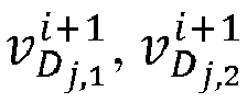

j on the axis V in the image frame Ti+1 respectively. - When the three vertexes of the triangle Δ D
j are respectively a matching feature point A, a matching feature point B, and a matching feature point C, a process of removing abnormal matching feature points is described by using the triangle Δ Dj as an example. A coordinate change value of a side length AB in the triangle Δ Dj is shown by the following formula (5):
- A coordinate change value of a side length BC in the triangle Δ D
j is shown by the following formula (6):
- A coordinate change value of a side length AC in the triangle Δ D
j is shown by the following formula (7):
- A counter may be allocated to each matching feature point in the q matching feature points. If the coordinate change value dAB of the side length AB in formula (5) is less than a change threshold (the change threshold may be preset), the side length AB may be determined as a target side length, and counters of two vertexes (namely, the matching feature point A and the matching feature point B) of the target side length AB is increased by 1; and if the coordinate change value dAB is greater than or equal to the change threshold, no processing may be performed on the counters of the matching feature point A and the matching feature point B. If the coordinate change value dBC of the side length BC in formula (6) is less than the change threshold, the side length BC may be determined as a target side length, and counters of two vertexes (namely, the matching feature point B and the matching feature point C) of the target side length BC is increased by 1; and if the coordinate change value dBC is greater than or equal to the change threshold, no processing may be performed on the counters of the matching feature point B and the matching feature point C. If the coordinate change value dAC of the side length AC in formula (7) is less than the change threshold, the side length AC may be determined as a target side length, and counters of two vertexes (namely, the matching feature point A and the matching feature point C) of the target side length AC is increased by 1; and if the coordinate change value dAC is greater than or equal to the change threshold, no processing may be performed on the counters of the matching feature point A and the matching feature point C.
- The computer device may circularly process each triangle in the candidate mesh plane graph according to formula (5) to formula (7) until the m triangles are all processed, to obtain total values of counters (namely, the total values of the normal verification parameters) respectively corresponding to the q matching feature points. If a total value of the counter of a matching feature point is greater than a parameter threshold (the parameter threshold may be preset, and for example, the parameter threshold is 4), the matching feature point may be determined as a normal matching feature point, and the matching feature point may be reserved; and if a total value of the counter of a matching feature point is less than or equal to the parameter threshold (for example, the parameter threshold is 4), the matching feature point may be determined as an abnormal matching feature point, and the abnormal matching feature point may be deleted.
- In step S207, the Delaunay triangulation network from which abnormal matching feature points are removed is obtained.
- The computer device may update, according to normal matching feature points, the candidate mesh plane graph to a target mesh plane graph corresponding to the image frame group Gi, for example, obtain a Delaunay triangulation network from which abnormal matching feature points are removed according to the normal matching feature points. That is, the computer device may delete triangles including the abnormal matching feature points from the candidate mesh plane graph, to form a final Delaunay triangulation network corresponding to the image frame group Gi.
- In an embodiment, the computer device may re-construct, according to the Delaunay triangulation processing described in step S205, a Delaunay triangulation network according to the normal matching feature points. The Delaunay triangulation network including the normal matching feature points may be referred to as the target mesh plane graph.
- Target Delaunay triangulation networks respectively corresponding to the N image frame groups may be obtained based on step S203 to step S207.
- In the embodiments of the present disclosur, in-vehicle image data corresponding to a driving vehicle is obtained, matching feature points between two adjacent image frames are extracted, a Delaunay triangulation network corresponding to the two adjacent image frames is constructed by using the matching feature points between the two adjacent image frames, and abnormal matching feature points are removed based on the Delaunay triangulation network. Therefore, the effectiveness of the matching feature points can be improved, and a motion state of the driving vehicle is determined based on the Delaunay triangulation network, thereby improving the evaluation accuracy of the motion state of the vehicle.
- Reference is made to
FIG. 10 , which is a schematic flowchart of a method for evaluating a motion state of a traffic tool according to an embodiment of the present disclosure. The method for evaluating a motion state of a traffic tool may be performed by a computer device, and the computer device may be a mobile terminal configured for the traffic tool. As shown inFIG. 10 , the method for evaluating a motion state of a traffic tool may include the following steps: S301 ti S306. - In step S301, in-vehicle image data is pre-processed (eliminate image noise and distortion).
- In step S302, image feature points of the in-vehicle image data are extracted.
- In step S303, feature points of adjacent image frames are matched.
- In step S304, a Delaunay triangulation network is established by using matching feature points.
- In step S305, abnormal matching feature points are removed based on the Delaunay triangulation network.
- In this embodiment of the present disclosure, an implementation procedure of the method for evaluating a motion state of a traffic tool is described by using an example in which the traffic tool is a driving vehicle and a target mesh plane graph is a Delaunay triangulation network. For specific implementations of step S301 to step S305, one may refer to step S201 to step S207 in the embodiment corresponding to
FIG. 8 , and details are not described herein again. - In step S306, a motion state of a vehicle is determined based on the Delaunay triangulation network.
- The computer device may determine a motion state of a driving vehicle according to triangles included in the Delaunay triangulation network, and a process of determining a motion state of a vehicle (or a process of evaluating a motion state of a vehicle) is described in detail based on
FIG. 11 to FIG. 14 .FIG. 11 andFIG. 12 describe a process of determining a static motion state, andFIG. 13 andFIG. 14 describe a process of determining a linear motion state of the vehicle. - Reference is made to
FIG. 11 , which is a schematic flowchart of determining a static state of a traffic tool based on a target mesh plane graph according to an embodiment of the present disclosure. As shown inFIG. 11 , the determining process of a static state of a traffic tool may include step S401 to step S405. - In step S401, a Delaunay triangulation network from which abnormal matching feature points are removed is obtained.
- The computer device may obtain an image frame group Gi in N image frame groups, and further obtain a target mesh plane graph H; corresponding to the image frame group Gi. The target mesh plane graph Hi includes M polygons, M is a positive integer, and i is a positive integer less than or equal to N. In this embodiment of the present disclosure, the target mesh plane graph H; may refer to a Delaunay triangulation network from which abnormal matching feature points are removed and corresponding to the image frame group Gi (for ease of description, the "Delaunay triangulation network from which abnormal matching feature points are removed and corresponding to the image frame group Gi" is referred to as a "Delaunay triangulation network corresponding to the image frame group Gi"). The image frame group Gi may include an image frame Ti and an image frame Ti+1, the Delaunay triangulation network corresponding to the image frame group Gi may include M triangles, and a minimum value of i is 1 and a maximum value thereof is N. For ease of description, the determining process of a static state of a vehicle is described by using the Delaunay triangulation network corresponding to the image frame group Gi as an example.
- In step S402, average coordinate change values of each triangle in the Delaunay triangulation network in a U-axis direction and a V-axis direction are calculated.
- The computer device may obtain image coordinate information of all matching feature points included in the Delaunay triangulation network in the image frame Ti and the image frame Ti+1 respectively, that is, image coordinate information of vertexes of each triangle in the Delaunay triangulation network in the image frame Ti and the image frame Ti+i. Further, the computer device may obtain average coordinate change values respectively corresponding to the M triangles in the Delaunay triangulation network (namely, the polygon in this embodiment of this application is a triangle) according to the image coordinate information of the vertexes of each triangle in the image frame Ti and the image frame Ti+i. The average coordinate change value herein may include average coordinate change values in a U-axis direction and in a V-axis direction in an image coordinate system.
- The Delaunay triangulation network corresponding to the image frame group Gi may be shown by the following formula (8):

- Ψrepresentd the Delaunay triangulation network (namely, the Delaunay triangulation network from which abnormal matching feature points are removed) corresponding to the image frame group Gi, Δ D
s1 represents a first triangle in the Delaunay triangulation network, and Δ DsM represents an Mth triangle in the Delaunay triangulation network. Image coordinate information of three vertexes (one vertex corresponds to one normal matching feature point) of any triangle Δ Dsj , j = 1,2, ... ..., M in the Delaunay triangulation network in the image frame Ti may be shown by the following formula (9):


j on the axis U in the image frame Ti respectively, and


j on the axis V in the image frame Ti respectively. - Image coordinate information of the three vertexes of the triangle Δ Ds
j in the image frame Ti+i may be shown by the following formula (10):
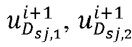

j on the axis U in the image frame Ti+1 respectively, and
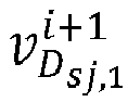

j on the axis V in the image frame Ti+1 respectively. - An average coordinate change value d u,sj of the triangle Δ Ds
j in the U-axis direction is shown by the following formula (11):
- An average coordinate change value d v,sj of the triangle Δ Ds
j in the V-axis direction is shown by the following formula (12):
- In step S403, average coordinate change values of all triangles in the Delaunay triangulation network in the U-axis direction and in the V-axis direction are combined to form two sequences.
- The computer device may form a sequence of the Delaunay triangulation network in the U-axis direction according to average coordinate change values of the M triangles in the Delaunay triangulation network in the U-axis direction, and the sequence may be shown by the following formula (13):

- Further, the computer device may form a sequence of the Delaunay triangulation network in the V-axis direction according to average coordinate change values of the M triangles in the Delaunay triangulation network in the V-axis direction, and the sequence may be shown by the following formula (14):

- In step S404, the two sequences are processed, to obtain average values, medians, and standard deviation values respectively corresponding to the two sequences.
- The computer device may process a sequence Φu and a sequence Φv to obtain statistical values associated with the Delaunay triangulation network. The statistical values may include an average value, a median, and a standard deviation value calculated according to the sequence Φu and an average value, a median, and a standard deviation value calculated according to the sequence Φv. The average values corresponding to the sequence Φu and the sequence Φv may be referred to as coordinate average values, the medians corresponding to the sequence Φu and the sequence Φv may be referred to as coordinate medians, and the standard deviation values corresponding to the sequence Φu and the sequence Φv may be referred to as coordinate standard deviation values. For a specific calculation process of the statistical values, one may refer to the description in the following embodiment corresponding to
FIG. 12 . - In step S405, the current vehicle is determined to be in a static state in a case that the average values, the medians, and the standard deviation values of the two sequences are all less than a given threshold.
- A target mesh plane graph may be constructed for each image frame group, namely, N Delaunay triangulation networks may be obtained according to normal matching feature points respectively corresponding to the N image frame groups, one Delaunay triangulation network may correspond to one sequence Φu and one sequence Φv. When statistical values respectively associated with the N Delaunay triangulation networks are all less than a first threshold, it may be determined that the motion state of the traffic tool is a static state. It may be understood that, the first threshold herein may include a first average value threshold, a first median threshold, and a standard deviation value threshold, and the first average value threshold, the first median threshold, and the standard deviation value threshold may be different preset values.
- In the embodiments of the present disclosure, in-vehicle image data of a traffic tool is obtained, matching feature points between two adjacent image frames are extracted, a Delaunay triangulation network corresponding to the two adjacent image frames is constructed by using the matching feature points between the two adjacent image frames, and abnormal matching feature points are removed based on the Delaunay triangulation network. Therefore, the effectiveness of the matching feature points can be improved, and a motion state of the traffic tool is determined based on the Delaunay triangulation network, thereby not only improving the evaluation accuracy of the motion state of the traffic tool, but also simplifying the evaluation procedure of the static state of the traffic tool, and thus improving the evaluation efficiency of the motion state of the traffic tool.
- Reference is made to
FIG. 12 , which is a schematic flowchart of determining a static state of a traffic tool based on a target mesh plane graph according to an embodiment of the present disclosure. In a possible implementation, the process of evaluating the static state of the traffic tool according to the target mesh plane graphs respectively corresponding to the N image frame groups may be performed as follows. The computer device may obtain a target mesh plane graph H; corresponding to an image frame group Gi of the N image frame groups. The target mesh plane graph Hi may include M polygons. Further, the computer device may obtain average coordinate change values respectively corresponding to the M polygons, rank the average coordinate change values respectively corresponding to the M polygons, determine the ranked average coordinate change values as a first coordinate sequence of the target mesh plane graph Hi, and determine statistical values associated with the target mesh plane graph H; according to the first coordinate sequence; and determine the motion state of the traffic tool as a static state in a case that statistical values respectively associated with N target mesh plane graphs are all less than a first threshold. - The first coordinate sequence may include a sequence of the target mesh plane graph H; in the U-axis direction (for example, a sequence obtained by ranking average coordinate change values included in a first sequence below in an ascending order) and a sequence of the target mesh plane graph H; in the V-axis direction (for example, a sequence obtained by ranking average coordinate change values included in a second sequence below in an ascending order). The statistical values may include a coordinate average value, a coordinate median, and a coordinate standard deviation value. The coordinate average value may include an average value corresponding to the sequence in the U-axis direction and an average value corresponding to the sequence in the V-axis direction, the coordinate median may include a median corresponding to the sequence in the U-axis direction and a median corresponding to the sequence in the V-axis direction, and the coordinate standard deviation value may include a standard deviation value corresponding to the sequence in the U-axis direction and a standard deviation value corresponding to the sequence in the V-axis direction. The first threshold may include a first average value threshold, a first median threshold, and a standard deviation value threshold which are different from each other.
- Processing of the sequence in the U-axis direction and the sequence in the V-axis direction are similar (as shown in
FIG. 12 ). For any sequence in a coordinate axis direction of an image coordinate system, a determining process of statistical values thereof may be performed as follows. The computer device may update the first coordinate sequence according to a median corresponding to the first coordinate sequence and the average coordinate change values included in the first coordinate sequence to obtain a second coordinate sequence. Further, the computer device may determine an effective value range of element values included in the second coordinate sequence according to a lower quartile corresponding to the second coordinate sequence and an upper quartile corresponding to the second coordinate sequence, and determine element values falling within the effective value range in the second coordinate sequence as a third coordinate sequence. The computer device may obtain an initial tagged array corresponding to the first coordinate sequence, and update the initial tagged array according to a lower quartile corresponding to the first coordinate sequence, an upper quartile corresponding to the first coordinate sequence, and a median corresponding to the third coordinate sequence to obtain a target tagged array. Further, the computer device may filter the average coordinate change values included in the first coordinate sequence according to a non-zero element in the target tagged array to update the first coordinate sequence to a fourth coordinate sequence, to obtain a coordinate average value, a coordinate median, and a coordinate standard deviation value corresponding to the fourth coordinate sequence. - As shown in
FIG. 12 , in a case that the target mesh plane graph Hi is a Delaunay triangulation network corresponding to the image frame group Gi, the determining process (or may be referred to as an evaluation process) of a static state of a traffic tool may include step S1201 to step S1223. - In step S1201, a Delaunay triangulation network from which abnormal matching feature points are removed is obtained.
- In step S1202, average coordinate change values of each triangle in the Delaunay triangulation network in a U-axis direction and a V-axis direction are calculated.
- For a specific implementation of step S1201 and step S1202, one may refer to step S401 and step S402 in the embodiment corresponding to
FIG. 11 , and details are not described herein again. - In step S1203, the average coordinate change value of each triangle in the U-axis direction froms a first sequence.
- The computer device may form a sequence of the Delaunay triangulation network in the U-axis direction according to average coordinate change values of M triangles in the Delaunay triangulation network in the U-axis direction. In this case, the sequence may be referred to as a first sequence, and the first sequence is expressed as the foregoing formula (13).
- In step S1204, elements of the first sequence are ranked in an ascending order.
- The first sequence may include the average coordinate change values of the M triangles of the Delaunay triangulation network in the U-axis direction respectively, and a first coordinate sequence in the U-axis direction may be obtained by ranking the average coordinate change values included in the first sequence in an ascending order. The first coordinate sequence in the U-axis direction may be shown by the following formula (15):



- In step S1205, a first tagged array is initialized.
- An initial tagged array corresponding to the first coordinate sequence in the U-axis direction is obtained. The initial tagged array may refer to an initialized first tagged array, and the initial tagged array may be set to:

- The initial tagged array mask[M] may be an array including M elements, namely, the number of elements in the initial tagged array mask[M] is the same as the number of triangles included in the Delaunay triangulation network.
- In step S1206, an upper quartile, a lower quartile, and a median of the ranked first sequence are calcualted.
- The ranked first sequence may be referred to as the first coordinate sequence




- When the computer device calculates the lower quartile of the first coordinate sequence


- Int in formula (17) represents rounding operation, and Dec represents a decimal calculation operation.
- When the computer device calculates the upper quartile of the first coordinate sequence


- When the computer device calculates the median of the first coordinate sequence


- In step S1207, the first tagged array is updated.
- After the upper quartile M3/4 and the lower quartile M1/4 corresponding to the first coordinate sequence


- In step S1208, the ranked first sequence is processed to obtain a new sequence.
- The computer device may update the first coordinate sequence


- In step S1209, an upper quartile, a lower quartile, and a median of the new sequence are calculated.
- The computer device may calculate a lower quartile, an upper quartile, and a median corresponding to the second coordinate sequence


M 1/4, the upper quartile of the second coordinate sequence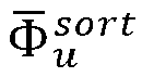
M 3/4, and the median of the second coordinate sequence
M 2/4. - Further, the computer device may determine an effective value range of element values included in the second coordinate sequence

M 1/4 and the upper quartileM 3/4 corresponding to the second coordinate sequence


M 1/4 - 1.5 · (M 3/4 -M 1/4) <


- The computer device may further calculate a median


- In step S1210, the first tagged array is updated.
- The computer device may update the first tagged array again according to the median


- In step S1211, a gross error in the first sequence is removed according to the first tagged array.
- The computer device may remove an average coordinate change value included in the first coordinate sequence


- In step S1212, an average value, a median, and a standard deviation value of the first sequence from which the gross error is removed are calculated.
- The computer device may obtain an average value Avgu, a median Medu, and a standard deviation value STDu of the fourth coordinate sequence Φ̃ u in the U-axis direction according to element values included in the fourth coordinate sequence Φ̃ u in the U-axis direction. In this case, the average value Avgu, the median Medu, and the standard deviation value STDu may be referred to as statistical values of the Delaunay triangulation network in the U-axis direction.
- In step S1213, the average coordinate change value of each triangle in the V-axis direction froms a second sequence.
- The computer device may form a sequence of the Delaunay triangulation network in the V-axis direction according to average coordinate change values of the M triangles in the Delaunay triangulation network in the V-axis direction. In this case, the sequence may be referred to as a second sequence, and the second sequence is expressed as the foregoing formula (14).
- In step S1214, elements of the second sequence are ranked in an ascending order.
- The second sequence may include the average coordinate change values of the M triangles of the Delaunay triangulation network in the V-axis direction respectively, and a first coordinate sequence in the V-axis direction may be obtained by ranking the average coordinate change values included in the second sequence in an ascending order. The first coordinate sequence in the V-axis direction may be shown by the following formula (21):


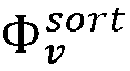

- In step S1215, a second tagged array is initialized.
- An initial tagged array corresponding to the first coordinate sequence in the V-axis direction is the same as the initial tagged array corresponding to the first coordinate sequence in the U-axis direction, namely, an initialized second tagged array is the same as the initialized first tagged array. The initialized second tagged array may be shown by the foregoing formula (16), and the second tagged array may also be an array including M elements.
- In step S1216, an upper quartile, a lower quartile, and a median of the ranked second sequence are calculated.
- In step S1217, the second tagged array is updated.
- In step S1218, the second sequence is processed to obtain a new sequence.
- In step S1219, an upper quartile, a lower quartile, and a median of the new sequence are calculated.
- In step S1220, the second tagged array is updated.
- In step S1221, a gross error in the second sequence is removed according to the second tagged array.
- In step S1222, an average value, a median, and a standard deviation value of the second sequence from which the gross error is removed are calculated.
- The computer device may process the first coordinate sequence





- In step S1223, it is determined that the vehicle is in a static state in a case that the average values, the medians, and the standard deviation values of the two sequences are all less than a given threshold; otherwise, it is determined that the vehicle is in a non-static state.
- According to the foregoing step S1201 to step S1222, the computer device may obtain statistical values respectively corresponding to the N Delaunay triangulation networks. That is, each Delaunay triangulation network may be associated with the average value Avgu, the median Medu, and the standard deviation value STDu in the U-axis direction and the average value Avgv, the median Medv, and the standard deviation value STDv in the V-axis direction. In a case that the statistical values respectively associated with the N Delaunay triangulation networks are all less than a given threshold (namely, the first threshold), it is determined that the motion state of the traffic tool is a static state. In a case that a statistical value in the statistical values respectively associated with the N Delaunay triangulation networks is greater than or equal to the given threshold (namely, the first threshold), it is determined that the motion state of the traffic tool is a non-static state.
- In an embodiment, when the first threshold includes a first average value threshold, a first median threshold, and a standard deviation value threshold which are different from each other, if the average values (including the average values Avgu and the average values Avgv) respectively associated with the N Delaunay triangulation networks are all less than the first average value threshold, the medians (including the medians Medu and the medians Medv) respectively associated with the N Delaunay triangulation networks are all less than the first median threshold, and the standard deviation values (including the standard deviation values STDu and the standard deviation values STDv) respectively associated with the N Delaunay triangulation networks are all less than the standard deviation value threshold, it is determined that the motion state of the traffic tool is a static state; otherwise, it is determined that the motion state of the traffic tool is a non-static state.
- In the embodiments of the present application, in-vehicle image data of a traffic tool is obtained, matching feature points between two adjacent image frames are extracted, a Delaunay triangulation network corresponding to the two adjacent image frames is constructed by using the matching feature points between the two adjacent image frames, and abnormal matching feature points are removed based on the Delaunay triangulation network. Therefore, the effectiveness of the matching feature points can be improved, and a motion state of the traffic tool is determined based on the Delaunay triangulation network, thereby not only improving the evaluation accuracy of the motion state of the traffic tool, but also simplifying the evaluation procedure of the static state of the traffic tool, and thus improving the evaluation efficiency of the motion state of the traffic tool. The motion state of the traffic tool is evaluated based on the in-vehicle image data and the Delaunay triangulation network, so that limitations to a scenario in which the traffic tool is located can be reduced, thereby effectively improving the evaluation accuracy of the motion state of the traffic tool in a complex scenario (such as city overpass) and thus improving the applicability of the method for evaluating a motion state of a traffic tool.
- Reference is made to
FIG. 13 , which is a schematic flowchart of determining a linear motion state based on a target mesh plane graph according to an embodiment of the present disclosure. In some implementations, the process of evaluating the linear motion state of the traffic tool according to the target mesh plane graphs respectively corresponding to the N image frame groups may be performed as follows. The computer device may obtain a target mesh plane graph H; corresponding to an image frame group Gi in the N image frame groups. The image frame group Gi includes an image frame Ti and an image frame Ti+i. The target mesh plane graph Hi includes M polygons, M is a positive integer, and i is a positive integer less than or equal to N. Further, the computer device may obtain a first direction of each side of the M polygons in the image frame Ti and a second direction of each side of the M polygons in the image frame Ti+i, determine a direction change value respectively corresponding to each side included in the M polygons according to the first direction and the second direction, generate a direction change sequence associated with the M polygons according to the direction change value respectively corresponding to the M polygons, and determine a direction average value and a direction median associated with the target mesh plane graph H; according to the direction change sequence. In a case that direction average values respectively associated with N target mesh plane graph and direction medians respectively associated with the N target mesh plane graphs are all less than a second threshold, the motion state of the traffic tool is determined as a linear motion state. - Any polygon in the M polygons may include multiple side lengths. For example, when the polygon is a triangle, the polygon may include three side lengths. In this case, the first direction may include directions of three sides in the image frame Ti respectively, the second direction may include directions of the three sides in the image frame Ti+i respectively, and the number of direction change sequences is 3 (for example, a third sequence, a fourth sequence, and a fifth sequence in the embodiment corresponding to
FIG. 14 ). When the polygon is a quadrangle, the polygon may include four side lengths. In this case, the first direction may include directions of four sides in the image frame Ti respectively, the second direction may include directions of the four sides in the image frame Ti+i respectively, and the number of direction change sequences is 4. The second threshold may include a second average value threshold and a second median threshold, and the second average value threshold may be different from the second median threshold. - As shown in
FIG. 13 , in a case that the target mesh plane graph Hi is a Delaunay triangulation network corresponding to the image frame group Gi, the determining process of a linear motion state of a traffic tool may include step S501 to step S506. - In step S501, a Delaunay triangulation network from which abnormal matching feature points are removed is obtained.
- For a specific implementation process of step S501, one may refer to step S401 in the embodiment corresponding to
FIG. 11 , and details are not described herein again. - In step S502, directions of three sides of each triangle in the Delaunay triangulation network in the image frame Ti are calculated.
- The computer device may obtain image coordinate information of all matching feature points included in the Delaunay triangulation network in the image frame Ti, that is, image coordinate information of vertexes of each triangle in the Delaunay triangulation network in the image frame Ti. The computer device may obtain directions of three sides included in each triangle in the Delaunay triangulation network (namely, the polygon in this embodiment of the present disclosure is a triangle) in the image frame Ti according to the image coordinate information of the vertexes of the triangle in the image frame Ti.
- The Delaunay triangulation network corresponding to the image frame group Gi may be shown by the foregoing formula (8), and the Delaunay triangulation network may include M triangles. Image coordinate information of three vertexes of any triangle Δ Ds
j ,j = 1,2, ......, M in the M triangles in the image frame Ti may be shown by the foregoing formula (9), and according to the foregoing formula (8) and formula (9), directions of three sides of the triangle Δ Dsj in the image frame Ti may be represented as:
- In which, atan represents an arc-tangent function,

j in the image frame Ti,
j in the image frame Ti, and
j in the image frame Ti. In this case,

j in the image frame Ti. - In step S503, directions of the three sides of each triangle in the Delaunay triangulation network in the image frame Ti+i are calculated.
- The computer device may obtain image coordinate information of all the matching feature points included in the Delaunay triangulation network in the image frame Ti+i, that is, image coordinate information of the vertexes of each triangle in the Delaunay triangulation network in the image frame Ti+i. The computer device may obtain directions of the three sides included in each triangle in the Delaunay triangulation network in the image frame Ti+i according to the image coordinate information of the vertexes of each triangle in the image frame Ti+i.
- Image coordinate information of three vertexes of any triangle Δ Ds
j in the M triangles in the image frame Ti+i may be shown by the foregoing formula (10). According to the foregoing formula (8) and formula (10), directions of three sides of the triangle Δ Dsj in the image frame Ti+i may be represented as:
- In which, atan represents an arc-tangent function,

j in the image frame Ti+1,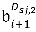
j in the image frame Ti+1, and
j in the image frame Ti+i. In this case,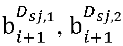
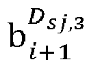
j in the image frame Ti+1. - In step S504, direction change values of the three sides of each triangle in the Delaunay triangulation network in the image frame Ti and in the image frame Ti+1 are calculated to form three sequences.
- The computer device may calculate direction change values of the three sides of the triangle Δ Ds
j between the image frame Ti and the image frame Ti+i, and the direction change values of the three sides may be shown by the following formula (24):
- In which,

j between the image frame Ti and the image frame Ti+1,
j between the image frame Ti and the image frame Ti+i, and
j between the image frame Ti and the image frame Ti+1. - The computer device obtains three direction change values respectively corresponding to the M triangles in the Delaunay triangulation network according to formula (22) to formula (24), and generates three sequences corresponding to the Delaunay triangulation network according to the three direction change values respectively corresponding to the M triangles. The three sequences may be shown in the following formula (25):

- In which, Ω1 Ω2, and Ω3 represent the three sequences corresponding to the Delaunay triangulation network. The three sequences may all be referred to as direction change sequences corresponding to the Delaunay triangulation network. The three sequences include a third sequence Ω1, a fourth sequence Ω2, and a fifth sequence Ω3.
- In step S505, the three sequences are processed to obtain average values and medians respectively corresponding to the three sequences.
- The computer device may process the third sequence Ω1 the fourth sequence Ω2, and the fifth sequence Ω3 corresponding to the Delaunay triangulation network, to obtain an average value Avg1 and a median Med1 of the third sequence Ω1 an average value Avg2 and a median Med2 of the fourth sequence Ω2, and an average value Avg3 and a median Med3 of the fifth sequence Q3. Further, the computer device may calculate an average value Avgb (the Avgb herein may be referred to as a direction average value) of the average value Avg1, the average value Avg2, and the average value Avg3, and the average value Avgb may be represented as: Avgb=(Avg1+Avg2+Avg3)/3. Further, the computer device may calculate an average value Medb (the Medb herein may be referred to as a direction median) of the median Med1, the median Med2, and the median Med3, and the average value Medb may be represented as: Medb=(Med1+Med2+Med3)/3.
- In step S506, it is determined that the current vehicle is in a linear motion state in a case that the average values and the medians of the three sequences are all less than a given threshold.
- A target mesh plane graph may be constructed for each image frame group, namely, N Delaunay triangulation networks may be obtained according to normal matching feature points respectively corresponding to the N image frame groups. One Delaunay triangulation network may correspond to one sequence Ω1 one sequence Ω2, and one sequence Ω3, and direction average values respectively associated with the N Delaunay triangulation networks and direction medians respectively associated with the N Delaunay triangulation networks may be calculated. In a case that the direction average values respectively associated with N Delaunay triangulation networks and the direction medians respectively associated with the N Delaunay triangulation networks are all less than a second threshold (which may be a preset threshold), the motion state of the traffic tool may be determined as a linear motion state. It may be understood that, the second threshold herein may include a second average value threshold and a second median threshold which are different from each other.
- In the embodiments of the present disclosure, in-vehicle image data of a traffic tool is obtained, matching feature points between two adjacent image frames are extracted, a Delaunay triangulation network corresponding to the two adjacent image frames is constructed by using the matching feature points between the two adjacent image frames, and abnormal matching feature points are removed based on the Delaunay triangulation network. Therefore, the effectiveness of the matching feature points can be improved, and a motion state of the traffic tool is determined based on the Delaunay triangulation network, thereby not only improving the evaluation accuracy of the motion state of the traffic tool, but also simplifying the evaluation procedure of the linear motion state of the traffic tool, and thus improving the evaluation efficiency of the motion state of the traffic tool.
- Refernece is made to
FIG. 14 , which is a schematic flowchart of determining a linear motion state based on a target mesh plane graph according to an embodiment of the present disclosure. As shown inFIG. 14 , the determining process of a linear motion state of a traffic tool may include step S1401 to step S1432. - In step S1401, a Delaunay triangulation network from which abnormal matching feature points are removed is obtained.
- In step S1402, directions of three sides of each triangle in the Delaunay triangulation network in the image frame Ti are calculated.
- In step S1403, directions of the three sides of each triangle in the Delaunay triangulation network in the image frame Ti+i are calculated.
- In step S1404, direction change values of the three sides of each triangle in the Delaunay triangulation network in the image frame Ti and in the image frame Ti+1 are calculated to form three sequences.
- For a specific implementation process of step S1401 to step S1404, one may refer to step S501 to step S504 in the embodiment corresponding to
FIG. 13 , and details are not described herein again. - In step S1405, elements of a third sequence are ranked in an ascending order.
- The computer device may obtain a ranked third sequence Ω1 by ranking the direction change values included in the third sequence Ω1 in formula (25) in an ascending order.
- In step S1406, a third tagged array is initialized.
- The computer device may obtain an initial tagged array corresponding to the third sequence Ω1. The initial tagged array may refer to an initialized third tagged array. When the Delaunay triangulation network includes M triangles, it may be determined that the initialized third tagged array is the same as the initialized first tagged array in the embodiment corresponding to
FIG. 12 , namely, the initialized third tagged array is shown by formula (16). - In step S1407, an upper quartile, a lower quartile, and a median of the ranked third sequence are calcualted.
- In step S1408, the third tagged array is updated.
- In step S1409, the third sequence is processed to obtain a new sequence.
- In setp S1410, an upper quartile, a lower quartile, and a median of the new sequence are calculated.
- In step S1411, the third tagged array is updated.
- In step S1412, a gross error in the third sequence is removed according to the third tagged array.
- In step S1413, an average value and a median of the third sequence from which the gross error is removed are calculated.
- The computer device may process the ranked third sequence Ω1 according to step S1407 to step S1413. For a processing of the ranked third sequence Ω1 one may refer to the processing of the first coordinate sequence


- It may be understood that, in the processing of the first coordinate sequence


- In step S1414, elements of a fourth sequence are ranked in an ascending order.
- The computer device may obtain a ranked fourth sequence Ω2 by ranking the direction change values included in the fourth sequence Ω2 in formula (25) in an ascending order.
- In step S1415, a fourth tagged array is initialized.
- The computer device may obtain an initial tagged array corresponding to the fourth sequence Ω2. The initial tagged array may refer to an initialized fourth tagged array. When the Delaunay triangulation network includes M triangles, it may be determined that the initialized fourth tagged array is the same as the initialized first tagged array in the embodiment corresponding to
FIG. 12 , namely, the initialized fourth tagged array is shown by formula (16). - In step S1416, an upper quartile, a lower quartile, and a median of the ranked fourth sequence are calculated.
- In step S1417, the fourth tagged array is updated.
- In step S1418, the fourth sequence is processed to obtain a new sequence.
- In step S1419, an upper quartile, a lower quartile, and a median of the new sequence are calculated.
- In step S1420, the fourth tagged array is updated.
- In step S1421, a gross error in the fourth sequence is removed according to the fourth tagged array.
- In step S 1422, an average value and a median of the fourth sequence from which the gross error is removed are calculated.
- The computer device may process the ranked fourth sequence Ω2 according to step S1416 to step S1422. For a processing of the ranked fourth sequence Ω2, one may refer to the processing of the first coordinate sequence


- It may be understood that, in the processing of the first coordinate sequence


- In step S1423, elements of a fifth sequence are ranked in an ascending order.
- The computer device may obtain a ranked fifth sequence Ω3 by ranking the direction change values included in the fifth sequence Ω3 in formula (25) in an ascending order.
- In step S1424, a fifth tagged array is initialized.
- The computer device may obtain an initial tagged array corresponding to the fifth sequence Ω3. The initial tagged array may refer to an initialized fifth tagged array. When the Delaunay triangulation network includes M triangles, it may be determined that the initialized fifth tagged array is the same as the initialized first tagged array in the embodiment corresponding to
FIG. 12 , namely, the initialized fifth tagged array is shown by formula (16). - In step S1425, an upper quartile, a lower quartile, and a median of the ranked fifth sequence are calculated.
- In step S1426, the fifth tagged array is updated.
- In step S1427, the fifth sequence is processed to obtain a new sequence.
- In step S1428, an upper quartile, a lower quartile, and a median of the new sequence are calculated.
- In step S1429, the fifth tagged array is updated.
- In step S1430, a gross error in the fifth sequence is removed according to the fifth tagged array.
- In
step S 1431, an average value and a median of the fifth sequence from which the gross error is removed are calculated. - The computer device may process the ranked fifth sequence Ω3 according to step S1425 to step S1431. For a processing of the ranked fifth sequence Ω3, one may be refer to the processing of the first coordinate sequence


- It may be understood that, in the processing of the first coordinate sequence


- In step S1432, it is determined that the vehicle is in a linear motion state in a case that the average values and the medians of the three sequences are all less than a given threshold.
- After obtaining the average value Avg1 and the median Med1 of the third sequence Ω1 the average value Avg2 and the median Med2 of the fourth sequence Ω2, and the average value Avg3 and the median Med3 of the fifth sequence Ω3, the computer device may determine an average value of the average value Avg1, the average value Avg2, and the average value Avg3 as a direction average value associated with the Delaunay triangulation network, and determine an average value of the median Med1, the median Med2, and the median Med3 as a direction median associated with the Delaunay triangulation network. Based on the same processing, the computer device may obtain direction average values respectively associated with N Delaunay triangulation networks and direction medians respectively associated with the N Delaunay triangulation networks. In a case that the direction average values respectively associated with N Delaunay triangulation networks and the direction medians respectively associated with the N Delaunay triangulation networks are all less than a second threshold (which may be a preset threshold), the motion state of the traffic tool is determined as a linear motion state. In a case that a direction average value greater than or equal to the second threshold exists in the direction average values associated with the N Delaunay triangulation networks or a direction median greater than or equal to the second threshold exists in the direction medians associated with the N Delaunay triangulation networks, the motion state of the traffic tool is determined as a non-linear motion state.
- In an embodiment, when the second threshold includes a second average value threshold and a second median value threshold, in a case that the direction average values respectively associated with the N Delaunay triangulation networks are all less than the second average value threshold, and the direction medians respectively associated with the N Delaunay triangulation networks are all less than the second median threshold, the motion state of the traffic tool is determined as a linear motion state; and in a case that a direction average value greater than or equal to the second average value threshold exists in the direction average values associated with the N Delaunay triangulation networks or a direction median greater than or equal to the second median threshold exists in the direction medians associated with the N Delaunay triangulation networks, the motion state of the traffic tool is determined as a non-linear motion state.
- In the embodiments of the present disclosure, in-vehicle image data of a traffic tool is obtained, matching feature points between two adjacent image frames are extracted, a Delaunay triangulation network corresponding to the two adjacent image frames is constructed by using the matching feature points between the two adjacent image frames, and abnormal matching feature points are removed based on the Delaunay triangulation network. Therefore, the effectiveness of the matching feature points can be improved, and a motion state of the traffic tool is determined based on the Delaunay triangulation network, thereby not only improving the evaluation accuracy of the motion state of the traffic tool, but also simplifying the evaluation procedure of the linear motion state of the traffic tool, and thus improving the evaluation efficiency of the motion state of the traffic tool. The motion state of the traffic tool is evaluated based on the in-vehicle image data and the Delaunay triangulation network, so that limitations to a scenario in which the traffic tool is located is reduced, thereby effectively improving the evaluation accuracy of the motion state of the traffic tool in a complex scenario (such as city overpass) and thus improving the applicability of the method for evaluating a motion state of a traffic tool.
- Reference is made to
FIG. 15 , which is a schematic structural diagram of an apparatus for evaluating a motion state of a traffic tool according to an embodiment of the present disclosure. As shown inFIG. 15 , theapparatus 1 for evaluating a motion state of a traffic tool may include: a first obtainingmodule 11, a second obtainingmodule 12, a meshgraph construction module 13, and a motionstate determining module 14. - The first obtaining
module 11 is configured to obtain target image data of the traffic tool, and combine every two adjacent image frames in the target image data to obtain N image frame groups, N being a positive integer. - The second obtaining
module 12 is configured to obtain matching feature points between two image frames included in each image frame group of the N image frame groups. - The mesh
graph construction module 13 is configured to construct target mesh plane graphs respectively corresponding to the N image frame groups according to the matching feature points corresponding to each image frame group. - The motion
state determining module 14 is configured to determine the motion state of the traffic tool according to the target mesh plane graphs respectively corresponding to the N image frame groups. - For specific function implementations of the first obtaining
module 11, the second obtainingmodule 12, the meshfigure construction module 13, and the motionstate determining module 14, one may refer to step S101 to step S104 in the embodiment corresponding toFIG. 3 , and details are not described herein again. - In some implementations, the first obtaining
module 11 may include adenoising processing unit 111, a distortion removingprocessing unit 112, and an imageframe combination unit 113. - The
denoising processing unit 111 is configured to obtain original image data of the traffic tool acquired by a photographing device, and perform denoising processing on the original image data to obtain denoised image data. - The distortion removing
processing unit 112 is configured to perform distortion removing processing on the denoised image data according to a device parameter of the photographing device, to obtain the target image data of the traffic tool. - The image
frame combination unit 113 is configured to divide the target image data into N+1 image frames, and combine every two adjavent image frames in the N+1 image frames to obtain the N image frame groups. - For specific function implementations of the
denoising processing unit 111, the distortion removingprocessing unit 112, and the imageframe combination unit 113, one may refer to step S202 in the embodiment corresponding toFIG. 6 , and details are not described herein again. - In some implementations, the second obtaining
module 12 may include an image framegroup selection unit 121, a featurepoint obtaining unit 122, and a featurepoint matching unit 123. - The image frame
group selection unit 121 is configured to obtain an image frame group Gi in the N image frame groups. The image frame group Gi includes an image frame Ti and an image frame Ti+i, i is a positive integer less than or equal to N. - The feature
point obtaining unit 122 is configured to obtain a first feature point set in the image frame Ti and a second feature point set in the image frame Ti+1. - The feature
point matching unit 123 is configured to perform feature point matching on the first feature point set and the second feature point set to obtain matching feature points between the image frame Ti and the image frame Ti+1. - For specific function implementations of the image frame
group selection unit 121, the featurepoint obtaining unit 122, and the featurepoint matching unit 123, one may be refer to step S102 in the embodiment corresponding toFIG. 3 , and details are not described herein again. - In some implementations, the feature
point obtaining unit 122 may include a scalespace construction subunit 1221, a first feature point set obtainingsubunit 1222, and a second feature point set obtainingsubunit 1223. - The scale
space construction subunit 1221 is configured to construct a scale space for the image frame Ti and the image frame Ti+i, search the scale space for a first key point position set corresponding to the image frame Ti, and search the scale space for a second key point position set corresponding to the image frame Ti+1. - The first feature point set obtaining
subunit 1222 is configured to determine, according to a local gradient corresponding to a first key point position included in the first key point position set, a first descriptive feature corresponding to the first key point position, and obtain the first feature point set of the image frame Ti according to the first key point position and the first descriptive feature. - The second feature point set obtaining
subunit 1223 is configured to determine, according to a local gradient corresponding to a second key point position included in the second key point position set, a second descriptive feature corresponding to the second key point position, and obtain the second feature point set of the image frame Ti+i according to the second key point position and the second descriptive feature. - For specific function implementations of the scale
space construction subunit 1221, the first feature point set obtainingsubunit 1222, and the second feature point set obtainingsubunit 1223, one may refer to step S102 in the embodiment corresponding toFIG. 3 , and details are not described herein again. - In some implementations, the feature
point matching unit 123 may include a featurepoint selection subunit 1231, a matchingdegree determining subunit 1232, and a matching featurepoint determining subunit 1233. - The feature
point selection subunit 1231 is configured to obtain a first feature point at from the first feature point set, and obtain a second feature point bk from the second feature point set. In which, t is a positive integer less than or equal to the number of feature points included in the first feature point set, and k is a positive integer less than or equal to the number of feature points included in the second feature point set. - The matching
degree determining subunit 1232 is configured to determine a matching degree between the first feature point at and the second feature point bk according to a first descriptive feature corresponding to the first feature point at and a second descriptive feature corresponding to the second feature point bk. - The matching feature
point determining subunit 1233 is configured to determine, in a case that the matching degree is greater than a matching threshold, the first feature point at and the second feature point bk as the matching feature points between the image frame Ti and the image frame Ti+1. - For specific function implementations of the feature
point selection subunit 1231, the matchingdegree determining subunit 1232, and the matching featurepoint determining subunit 1233, one may be refer to step S102 in the embodiment corresponding toFIG. 3 , and details are not described herein again. - In some implementations, the mesh
graph construction module 13 may include a matching featurepoint obtaining unit 131, an initial linkedlist obtaining unit 132, an associatedpolygon obtaining unit 133, a candidatepolygon generation unit 134, apolygon conversion unit 135, and a target meshgraph generation unit 136. - The matching feature
point obtaining unit 131 is configured to obtain q matching feature points between an image frame Ti and an image frame Ti+i included in an image frame group Gi, and determine matching coordinate information respectively corresponding to the q matching feature points according to image coordinate information of each matching feature point of the q matching feature points in the image frame Ti and the image frame Ti+1 respectively. The image frame group G; belongs to the N image frame groups, i is a positive integer less than or equal to N, and q is a positive integer; - The initial linked
list obtaining unit 132 is configured to obtain an initial polygon linked list associated with the q matching feature points according to the matching coordinate information respectively corresponding to the q matching feature points. - The associated
polygon obtaining unit 133 is configured to obtain, for a matching feature point cr in the q matching feature points, an associated polygon matching with the matching feature point cr from the initial polygon linked list. A circumscribed circle of the associated polygon includes the matching feature point cr, and r is a positive integer less than or equal to q. - The candidate
polygon generation unit 134 is configured to delete a common side of the associated polygon, and connect the matching feature point cr to vertexes of the associated polygon to generate a candidate polygon corresponding to the matching feature point cr. - The
polygon conversion unit 135 is configured to convert the candidate polygon into a target polygon corresponding to the matching feature point cr, and add the target polygon to the initial polygon linked list. A circumscribed circle of the target polygon does not include any matching feature point. - The target mesh
graph generation unit 136 is configured to determine the initial polygon linked list as a target polygon linked list in a case that target polygons respectively corresponding to the q matching feature points are all added to the initial polygon linked list, and generate a target mesh plane graph corresponding to the image frame group G; according to the target polygon linked list. - For specific function implementations of the matching feature
point obtaining unit 131, the initial linkedlist obtaining unit 132, the associatedpolygon obtaining unit 133, the candidatepolygon generation unit 134, thepolygon conversion unit 135, and the target meshgraph generation unit 136, one may refer to step S205 in the embodiment corresponding toFIG. 6 , and details are not described herein again. - In some implementations, the target mesh
graph generation unit 136 may include apolygon selection subunit 1361, a vertex coordinate obtainingsubunit 1362, a coordinate changevalue determining subunit 1363, a parameter totalvalue obtaining subunit 1364, and an abnormalpoint deleting subunit 1365. - The
polygon selection subunit 1361 is configured to generate a candidate mesh plane graph corresponding to the image frame group G; according to the target polygon linked list, and obtain a polygon Dj from the candidate mesh plane graph, where j is a positive integer less than or equal to the number of polygons included in the candidate mesh plane graph. - The vertex coordinate obtaining
subunit 1362 is configured to obtain first vertex coordinates of matching feature points corresponding to the polygon Dj in the image frame Ti, and obtain second vertex coordinates of the matching feature points corresponding to the polygon Dj in the image frame Ti+i. - The coordinate change
value determining subunit 1363 is configured to determine a coordinate change value corresponding to each side length included in the polygon Dj according to the first vertex coordinates and the second vertex coordinates. - The parameter total
value obtaining subunit 1364 is configured to determine a side length whose coordinate change value is less than a change threshold as a target side length, accumulate normal verification parameters corresponding to matching feature points on two ends of the target side length to obtain a total value of a normal verification parameter corresponding to each of the matching feature points of the polygon Dj. - The abnormal
point deleting subunit 1365 is configured to determine a matching feature point whose total value of the normal verification parameter is greater than a parameter threshold as a normal matching feature point, and update the candidate mesh plane graph to the target mesh plane graph corresponding to the image frame group G; according to the normal matching feature point. - For specific function implementations of the
polygon selection subunit 1361, the vertex coordinate obtainingsubunit 1362, the coordinate changevalue determining subunit 1363, the parameter totalvalue obtaining subunit 1364, and the abnormalpoint deleting subunit 1365, one may refer to step S206 and step S207 in the embodiment corresponding toFIG. 6 , and details are not described herein again. - In some implementations, the motion
state determining module 14 may include a first meshgraph selection unit 141, aranking unit 142, a statisticalvalue determining unit 143, and a staticstate determining unit 144. - The first mesh
graph selection unit 141 is configured to obtain a target mesh plane graph H; corresponding to an image frame group Gi in the N image frame groups. The target mesh plane graph Hi includes M connected but non-overlapping polygons, a circumscribed circle of each of the polygons does not include any matching feature point, M is a positive integer, and i is a positive integer less than or equal to N. - The
ranking unit 142 is configured to obtain average coordinate change values respectively corresponding to the M polygons, rank the average coordinate change values respectively corresponding to the M polygons, and determine the ranked average coordinate change values as a first coordinate sequence of the target mesh plane graph Hi. - The statistical
value determining unit 143 is configured to determine a statistical value associated with the target mesh plane graph H; according to the first coordinate sequence. - The static
state determining unit 144 is configured to determine the motion state of the traffic tool as a static state in a case that statistical values respectively associated with N target mesh plane graphs are all less than a first threshold. - For specific function implementations of the first mesh
graph selection unit 141, theranking unit 142, the statisticalvalue determining unit 143, and the staticstate determining unit 144, one may refer to the embodiment corresponding toFIG. 11 , and details are not described herein again. - In some implementations, the statistical value associated with the target mesh plane graph Hi includes a coordinate average value, a coordinate median, and a coordinate standard deviation value.
- The statistical
value determining unit 143 may include a firstsequence update subunit 1431, a secondsequence update subunit 1432, a taggedarray update subunit 1433, and afiltering subunit 1434. - The first
sequence update subunit 1431 is configured to update the first coordinate sequence according to a median corresponding to the first coordinate sequence and the average coordinate change values included in the first coordinate sequence to obtain a second coordinate sequence. - The second
sequence update subunit 1432 is configured to update the second coordinate sequence according to a lower quartile corresponding to the second coordinate sequence and an upper quartile corresponding to the second coordinate sequence to obtain a third coordinate sequence. - The tagged
array update subunit 1433 is configured to obtain an initial tagged array corresponding to the first coordinate sequence, and update the initial tagged array according to a lower quartile corresponding to the first coordinate sequence, an upper quartile corresponding to the first coordinate sequence, and a median corresponding to the third coordinate sequence to obtain a target tagged array. - The
filtering subunit 1434 is configured to filter the average coordinate change values included in the first coordinate sequence according to a non-zero element in the target tagged array to update the first coordinate sequence to a fourth coordinate sequence, and obtain a coordinate average value, a coordinate median, and a coordinate standard deviation value corresponding to the fourth coordinate sequence. - The second
sequence update subunit 1432 is configured to: - determine an effective value range of element values included in the second coordinate sequence according to the lower quartile corresponding to the second coordinate sequence and the upper quartile corresponding to the second coordinate sequence; and
- determine element values within the effective value range in the second coordinate sequence as the third coordinate sequence.
- For specific function implementations of the first
sequence update subunit 1431, the secondsequence update subunit 1432, the taggedarray update subunit 1433, and thefiltering subunit 1434, one may refer to step S1203 to step S1222 in the embodiment corresponding toFIG. 12 , and details are not described herein again. - In some implementations, the motion
state determining module 14 may include a second meshgraph selection unit 145, adirection obtaining unit 146, a direction changevalue determining unit 147, a direction changesequence generation unit 148, and a linear motionstate determining unit 149. - The second mesh
graph selection unit 145 is configured to obtain a target mesh plane graph H; corresponding to an image frame group Gi in the N image frame groups. The image frame group Gi includes an image frame Ti and an image frame Ti+i, the target mesh plane graph Hi includes M connected but non-overlapping polygons, a circumscribed circle of each of the polygons does not include any matching feature point, M is a positive integer, and i is a positive integer less than or equal to N. - The
direction obtaining unit 146 is configured to obtain a first direction of each side of the M polygons in the image frame Ti, and obtain a second direction of each side of the M polygons in the image frame Ti+1. - The direction change
value determining unit 147 is configured to determine a direction change value corresponding to each side of the M polygons according to the first direction and the second direction. - The direction change
sequence generation unit 148 is configured to generate a direction change sequence associated with the M polygons according to direction change values respectively corresponding to the M polygons, and determine a direction average value and a direction median associated with the target mesh plane graph H; according to the direction change sequence. - The linear motion
state determining unit 149 is configured to determine the motion state of the traffic tool as a linear motion state in a case that direction average values respectively associated with N target mesh plane graphs and direction medians respectively associated with the N target mesh plane graphs are all less than a second threshold. - For specific function implementations of the second mesh
graph selection unit 145, thedirection obtaining unit 146, the direction changevalue determining unit 147, the direction changesequence generation unit 148, and the linear motionstate determining unit 149, one may refer to the embodiments corresponding toFIG. 13 andFIG. 14 , and details are not described herein again. - In some implementations, the
apparatus 1 for evaluating a motion state of a traffic tool may further include afirst positioning module 15 and asecond positioning module 16. - The
first positioning module 15 is configured to determine positioning information of the traffic tool by using a positioning and navigation system in a case that the motion state of the traffic tool is the static state. - The
second positioning module 16 is configured to determine, in a case that the motion state of the traffic tool is the linear motion state, a motion direction of the traffic tool according to the linear motion state, and determine the positioning information of the traffic tool according to the motion direction and the positioning and navigation system. - For specific function implementations of the
first positioning module 15 and thesecond positioning module 16, one may refer to step S104 in the embodiment corresponding toFIG. 3 , and details are not described herein again. - In the embodiments of the present disclosure, in-vehicle image data corresponding to a driving vehicle is obtained, matching feature points between two adjacent image frames are extracted, a target mesh plane graph corresponding to the two adjacent image frames is constructed by using the matching feature points between the two adjacent image frames, and abnormal matching feature points are removed based on the target mesh plane graph. Therefore, the effectiveness of the matching feature points can be improved, and the motion state of the traffic tool is determined based on the target mesh plane graph, thereby not only improving the evaluation accuracy of the motion state of the traffic tool, but also simplifying the evaluation procedure of the motion state of the traffic tool, and thus improving the evaluation efficiency of the motion state of the traffic tool. The motion state of the traffic tool is evaluated based on the in-vehicle image data and the target mesh plane graph, so that limitations to a scenario in which the traffic tool is located is reduced, thereby effectively improving the evaluation accuracy of the motion state of the traffic tool in a complex scenario (such as city overpass) and thus improving the applicability of the method for evaluating a motion state of a traffic tool. The motion state of the traffic tool can effectively assist the positioning and navigation system, thereby improving the positioning precision of a terminal configured for the traffic tool.
- Reference is made to
FIG. 16 , which is a schematic structural diagram of a computer device according to an embodiment of the present disclosure. As shown inFIG. 16 , thecomputer device 1000 may include: aprocessor 1001, anetwork interface 1004, and amemory 1005. Thecomputer device 1000 may further include auser interface 1003 and at least onecommunication bus 1002. Thecommunication bus 1002 is configured to implement connection and communication between these components. Theuser interface 1003 may include a display and a keyboard. In an embodiment, theuser interface 1003 may further include a standard wired interface and a wireless interface. In an embodiment, thenetwork interface 1004 may include a standard wired interface and a standard wireless interface (such as a Wi-Fi interface). Thememory 1005 may be a high-speed RAM, or may be a non-volatile memory, for example, at least one magnetic disk memory. In an embodiment, thememory 1005 may also be at least one storage apparatus being away from theprocessor 1001. As shown inFIG. 16 , thememory 1005 serving as a computer-readable storage medium may include an operating system, a network communication module, a user interface module, and a device-control application program. - In the
computer device 1000 shown inFIG. 16 , thenetwork interface 1004 may provide a network communication function, theuser interface 1003 is an interface for inputting by a user, and theprocessor 1001 may be configured to invoke the device-control application program stored in thememory 1005 to perform the following operations: - obtaining target image data of the traffic tool, and combining every two adjancent image frames in the target image data to obtain N image frame groups, N being a positive integer;
- obtaining matching feature points between two image frames included in each image frame group of the N image frame groups;
- constructing target mesh plane graphs respectively corresponding to the N image frame groups according to the matching feature points corresponding to each image frame group; and
- determining the motion state of the traffic tool according to the target mesh plane graphs respectively corresponding to the N image frame groups.
- It is to be understood that, the
computer device 1000 described in this embodiment of the present disclosure may implement the method for evaluating a motion state of a traffic tool in the embodiment corresponding to any one ofFIG. 3 ,FIG. 6 , orFIG. 10 toFIG. 14 , or the functions of theapparatus 1 for evaluating a motion state of a traffic tool in the embodiment corresponding toFIG. 15 , and details are not described herein again. In addition, beneficial effects achieved by using the same method are not described herein again. - In addition, a computer-readable storage medium is further provided according to embodiments of the present disclosure. The computer-readable storage medium stores a computer program executed by the
apparatus 1 for evaluating a motion state of a traffic tool mentioned above, and the computer program includes program instructions. When executing the program instructions, a processor can implement the method for evaluating a motion state of a traffic tool in the embodiment corresponding to any one ofFIG. 3 ,FIG. 6 , orFIG. 10 toFIG. 14 . Therefore, details are not described herein again. In addition, beneficial effects achieved by using the same method are not described herein again. For technical details that are not disclosed in the embodiments of the computer-readable storage medium of the present disclosure, one may refer to the method embodiments of the present disclosure. In an example, the program instructions may be deployed to be executed on a computing device, or deployed to be executed on mutiple computing devices at the same position, or deployed to be executed on multiple computing devices that are distributed in multiple positions and interconnected through a communication network. The multiple computing devices that are distributed in multiple positions and interconnected through a communication network may form a blockchain system. - In addition, a computer program product or a computer program is further provided according to embodiments of the presnt disclosure. The computer program product or the computer program may include computer instructions, and the computer instructions may be stored in a computer-readable storage medium. A processor of a computer device reads the computer instructions from the computer-readable storage medium, and executes the computer instructions, to cause the computer device to perform the method for evaluating a motion state of a traffic tool in the embodiment corresponding to any one of
FIG. 3 ,FIG. 6 , orFIG. 10 toFIG. 14 . Therefore, details are not described herein again. In addition, beneficial effects achieved by using the same method are not described herein again. For technical details that are not disclosed in the embodiment of the computer program product or the computer program of the present disclosure, one may be refer to the description of the method embodiments of the present disclosure. - For ease of the description, the foregoing method embodiments are illustrated as a series of action combinations. However, a person skilled in the art is to know that the present disclosure is not limited to the described sequence of the actions. According to the present disclosure, some steps may be performed in another sequence or may be simultaneously performed. In addition, a person skilled in the art is further to understand that the embodiments described in this specification are exemplary embodiments, and the involved actions and modules are unnecessary for the present disclosure.
- A sequence of the steps of the method in the embodiments of the present disclosure may be adjusted, and certain steps may also be combined or deleted according to an actual requirement.
- The modules in the apparatus in the embodiments of the present disclosure may be combined, divided, and deleted according to an actual requirement.
- A person of ordinary skill in the art may understand that all or some of the procedures of the methods in the foregoing embodiments may be implemented by a computer program instructing relevant hardware. The computer program may be stored in a computer-readable storage medium. When the program is executed, the foregoing method embodiments may be performed. The foregoing storage medium may include a magnetic disc, an optical disc, a read-only memory (ROM), a random access memory (RAM), or the like.
- The foregoing disclosed is merely exemplary embodiments of the present disclosure, and the embodiments are not intended to limit the protection scope of the present disclosure. Therefore, equivalent variations made in accordance with the claims of the present disclosure shall fall within the scope of the present disclosure.
Claims (16)
- A method for evaluating a motion state of a traffic tool such as a vehicle, performed by a computer device, the method comprising:obtaining target image data of the traffic tool, and combining every two adjacent image frames in the target image data to obtain N image frame groups, N being a positive integer;obtaining matching feature points between two image frames comprised in each image frame group of the N image frame groups;constructing target mesh plane graphs respectively corresponding to the N image frame groups according to the matching feature points corresponding to each image frame group; anddetermining the motion state of the traffic tool according to the target mesh plane graphs respectively corresponding to the N image frame groups.
- The method according to claim 1, wherein the obtaining target image data of the traffic tool, and combining every two adjacent image frames in the target image data to obtain N image frame groups comprises:obtaining original image data of the traffic tool acquired by a photographing device, and performing denoising processing on the original image data to obtain denoised image data;performing distortion removing processing on the denoised image data according to a device parameter of the photographing device, to obtain the target image data of the traffic tool; anddividing the target image data into N+1 image frames, and combining every two adjacent image frames in the N+1 image frames to obtain the N image frame groups.
- The method according to claim 1, wherein the obtaining matching feature points between two image frames comprised in each image frame group of the N image frame groups comprises:obtaining an image frame group Gi in the N image frame groups, wherein the image frame group Gi comprises an image frame Ti and an image frame Ti+i, and i is a positive integer less than or equal to N;obtaining a first feature point set in the image frame Ti and a second feature point set in the image frame Ti+i; andperforming feature point matching on the first feature point set and the second feature point set to obtain matching feature points between the image frame Ti and the image frame Ti+i.
- The method according to claim 3, wherein the obtaining a first feature point set in the image frame Ti and a second feature point set in the image frame Ti+1 comprises:constructing a scale space for the image frame Ti and the image frame Ti+1, searching the scale space for a first key point position set corresponding to the image frame Ti, and searching the scale space for a second key point position set corresponding to the image frame Ti+i;determining, according to a local gradient corresponding to a first key point position comprised in the first key point position set, a first descriptive feature corresponding to the first key point position, and obtaining the first feature point set of the image frame Ti according to the first key point position and the first descriptive feature; anddetermining, according to a local gradient corresponding to a second key point position comprised in the second key point position set, a second descriptive feature corresponding to the second key point position, and obtaining the second feature point set of the image frame Ti according to the second key point position and the second descriptive feature.
- The method according to claim 3, wherein the performing feature point matching on the first feature point set and the second feature point set to obtain matching feature points between the image frame Ti and the image frame Ti+1 comprises:obtaining a first feature point at from the first feature point set, and obtaining a second feature point bk from the second feature point set, wherein t is a positive integer less than or equal to the number of feature points comprised in the first feature point set, and k is a positive integer less than or equal to the number of feature points comprised in the second feature point set;determining a matching degree between the first feature point at and the second feature point bk according to a first descriptive feature corresponding to the first feature point at and a second descriptive feature corresponding to the second feature point bk; anddetermining, in a case that the matching degree is greater than a matching threshold, the first feature point at and the second feature point bk as the matching feature points between the image frame Ti and the image frame Ti+1.
- The method according to claim 1, wherein the constructing target mesh plane graphs respectively corresponding to the N image frame groups according to the matching feature points corresponding to each image frame group comprises:obtaining q matching feature points between an image frame Ti and an image frame Ti+i comprised in an image frame group Gi, and determining matching coordinate information respectively corresponding to the q matching feature points according to image coordinate information of the q matching feature points in the image frame Ti and the image frame Ti+1 respectively, wherein the image frame group G; belongs to the N image frame groups, i is a positive integer less than or equal to N, and q is a positive integer;obtaining an initial polygon linked list associated with the q matching feature points according to the matching coordinate information respectively corresponding to the q matching feature points;obtaining, for a matching feature point cr in the q matching feature points, an associated polygon matching with the matching feature point cr from the initial polygon linked list, wherein a circumscribed circle of the associated polygon comprises the matching feature point cr, and r is a positive integer less than or equal to q;deleting a common side of the associated polygon, and connecting the matching feature point cr to vertexes of the associated polygon to generate a candidate polygon corresponding to the matching feature point cr;converting the candidate polygon into a target polygon corresponding to the matching feature point cr, and adding the target polygon to the initial polygon linked list, wherein a circumscribed circle of the target polygon does not comprise the matching feature point; anddetermining the initial polygon linked list as a target polygon linked list in a case that target polygons respectively corresponding to the q matching feature points are all added to the initial polygon linked list, and generating a target mesh plane graph corresponding to the image frame group G; according to the target polygon linked list.
- The method according to claim 6, wherein the generating a target mesh plane graph corresponding to the image frame group G; according to the target polygon linked list comprises:generating a candidate mesh plane graph corresponding to the image frame group G; according to the target polygon linked list, and obtaining a polygon Dj from the candidate mesh plane graph, wherein j is a positive integer less than or equal to the number of polygons comprised in the candidate mesh plane graph;obtaining first vertex coordinates of matching feature points corresponding to the polygon Dj in the image frame Ti, and obtaining second vertex coordinates of the matching feature points corresponding to the polygon Dj in the image frame Ti+1;determining a coordinate change value corresponding to each side length of the polygon Dj according to the first vertex coordinates and the second vertex coordinates;determining a side length whose coordinate change value is less than a change threshold as a target side length, accumulating normal verification parameters corresponding to matching feature points on two ends of the target side length to obtain a total value of the normal verification parameter corresponding to each of the matching feature points of the polygon Dj; anddetermining a matching feature point whose total value of the normal verification parameter is greater than a parameter threshold as a normal matching feature point, and updating the candidate mesh plane graph to the target mesh plane graph corresponding to the image frame group G; according to the normal matching feature point.
- The method according to claim 1, wherein the determining the motion state of the traffic tool according to the target mesh plane graphs respectively corresponding to the N image frame groups comprises:obtaining a target mesh plane graph Hi corresponding to an image frame group Gi in the N image frame groups, wherein the target mesh plane graph Hi comprises M connected but non-overlapping polygons, a circumscribed circle of each of the polygons does not comprise the matching feature point, M is a positive integer, and i is a positive integer less than or equal to N;obtaining average coordinate change values respectively corresponding to the M polygons, ranking the average coordinate change values respectively corresponding to the M polygons, and determining the ranked average coordinate change values as a first coordinate sequence of the target mesh plane graph Hi;determining a statistical value associated with the target mesh plane graph Hi according to the first coordinate sequence; anddetermining the motion state of the traffic tool as a static state in a case that statistical values respectively associated with N target mesh plane graphs are all less than a first threshold.
- The method according to claim 8, wherein the statistical value associated with the target mesh plane graph Hi comprises a coordinate average value, a coordinate median, and a coordinate standard deviation value; and
wherein the determining a statistical value associated with the target mesh plane graph Hi according to the first coordinate sequence comprises:updating the first coordinate sequence according to a median of the first coordinate sequence and the average coordinate change values comprised in the first coordinate sequence to obtain a second coordinate sequence;updating the second coordinate sequence according to a lower quartile corresponding to the second coordinate sequence and an upper quartile corresponding to the second coordinate sequence to obtain a third coordinate sequence;obtaining an initial tagged array corresponding to the first coordinate sequence, and updating the initial tagged array according to a lower quartile corresponding to the first coordinate sequence, a lower quartile corresponding to the first coordinate sequence, and a median of the third coordinate sequence, to obtain a target tagged array; andfiltering the average coordinate change values comprised in the first coordinate sequence according to a non-zero element in the target tagged array to update the first coordinate sequence to a fourth coordinate sequence, and obtaining a coordinate average value, a coordinate median, and a coordinate standard deviation value corresponding to the fourth coordinate sequence. - The method according to claim 9, wherein the updating the second coordinate sequence according to a lower quartile corresponding to the second coordinate sequence and an upper quartile corresponding to the second coordinate sequence to obtain a third coordinate sequence comprises:determining an effective value range of element values comprised in the second coordinate sequence according to the lower quartile corresponding to the second coordinate sequence and the upper quartile corresponding to the second coordinate sequence; anddetermining element values within the effective value range in the second coordinate sequence as the third coordinate sequence.
- The method according to claim 1, wherein the determining the motion state of the traffic tool according to the target mesh plane graphs comprises:obtaining a target mesh plane graph H; corresponding to an image frame group Gi in the N image frame groups, wherein the image frame group Gi comprises an image frame Ti and an image frame Ti+i, the target mesh plane graph Hi comprises M connected but non-overlapping polygons, a circumscribed circle of each of the polygons does not comprise the matching feature point, M is a positive integer, and i is a positive integer less than or equal to N;obtaining a first direction of each side of the M polygons in the image frame Ti, and obtaining a second direction of each side of the M polygons in the image frame Ti+1;determining a direction change value corresponding to each side of the M polygons according to the first direction and the second direction;generating a direction change sequence associated with the M polygons according to direction change values respectively corresponding to the M polygons, and determining a direction average value and a direction median associated with the target mesh plane graph H; according to the direction change sequence; anddetermining the motion state of the traffic tool as a linear motion state in a case that direction average values respectively associated with N target mesh plane graphs and direction medians respectively associated with the N target mesh plane graphs are all less than a second threshold.
- The method according to any one of claims 1 to 11, further comprising:determining positioning information of the traffic tool by using a positioning and navigation system in a case that the motion state of the traffic tool is static; anddetermining, in a case that the motion state of the traffic tool is a linear motion state, a motion direction of the traffic tool according to the linear motion state, and determining the positioning information of the traffic tool according to the motion direction by using the positioning and navigation system.
- An apparatus for evaluating a motion state of a traffic tool, comprising:a first obtaining module, configured to obtain target image data of the traffic tool, and combine every two adjancent image frames in the target image data to obtain N image frame groups, N being a positive integer;a second obtaining module, configured to obtain matching feature points between two image frames comprised in each image frame group of the N image frame groups;a mesh graph construction module, configured to construct target mesh plane graphs respectively corresponding to the N image frame groups according to the matching feature points corresponding to each image frame group; anda motion state determining module, configured to determine the motion state of the traffic tool according to the target mesh plane graphs respectively corresponding to the N image frame groups.
- A computer device, comprising a memory and a processor,
wherein the processor is connected to the memory, the memory is configured to store a computer program, and the processor is configured to invoke the computer program, to cause the computer device to perform the method according to any one of claims 1 to 12. - A computer-readable storage medium, storing a computer program, wherein the computer program is adapted to be loaded and executed by a processor, to cause a computer device comprising the processor to perform the method according to any of claims 1 to 12.
- A computer program product comprising instructions, wherein the computer program product, when run on a computer, causes the computer to perform the method according to any one of claims 1 to 12.
Applications Claiming Priority (2)
| Application Number | Priority Date | Filing Date | Title |
|---|---|---|---|
| CN202110100057.9A CN112734290B (en) | 2021-01-25 | 2021-01-25 | Vehicle motion state evaluation method, device, equipment and medium |
| PCT/CN2022/072436 WO2022156652A1 (en) | 2021-01-25 | 2022-01-18 | Vehicle motion state evaluation method and apparatus, device, and medium |
Publications (2)
| Publication Number | Publication Date |
|---|---|
| EP4198897A1 true EP4198897A1 (en) | 2023-06-21 |
| EP4198897A4 EP4198897A4 (en) | 2024-06-19 |
Family
ID=75593971
Family Applications (1)
| Application Number | Title | Priority Date | Filing Date |
|---|---|---|---|
| EP22742131.0A Pending EP4198897A4 (en) | 2021-01-25 | 2022-01-18 | VEHICLE MOTION STATE EVALUATION METHOD AND APPARATUS, DEVICE AND MEDIUM |
Country Status (4)
| Country | Link |
|---|---|
| US (1) | US12361566B2 (en) |
| EP (1) | EP4198897A4 (en) |
| CN (1) | CN112734290B (en) |
| WO (1) | WO2022156652A1 (en) |
Families Citing this family (4)
| Publication number | Priority date | Publication date | Assignee | Title |
|---|---|---|---|---|
| CN112734290B (en) | 2021-01-25 | 2022-02-11 | 腾讯科技(深圳)有限公司 | Vehicle motion state evaluation method, device, equipment and medium |
| CN112558125B (en) * | 2021-02-22 | 2021-05-25 | 腾讯科技(深圳)有限公司 | Vehicle positioning method, related device, equipment and storage medium |
| CN117058563B (en) * | 2023-07-03 | 2025-09-02 | 中国人民解放军92728部队 | A visually assisted landing method and system for shipborne helicopters based on image recognition |
| CN119991736A (en) * | 2025-01-17 | 2025-05-13 | 南京先维信息技术有限公司 | A method for detecting abnormal behavior of highway vehicles based on deep learning |
Family Cites Families (17)
| Publication number | Priority date | Publication date | Assignee | Title |
|---|---|---|---|---|
| US7460730B2 (en) * | 2005-08-04 | 2008-12-02 | Microsoft Corporation | Video registration and image sequence stitching |
| US8660723B2 (en) * | 2012-06-29 | 2014-02-25 | Mitsubishi Electric Research Laboratories, Inc. | Method for determining run-curves for vehicles in real-time subject to dynamic travel time and speed limit constraint |
| US9070289B2 (en) * | 2013-05-10 | 2015-06-30 | Palo Alto Research Incorporated | System and method for detecting, tracking and estimating the speed of vehicles from a mobile platform |
| US9025825B2 (en) * | 2013-05-10 | 2015-05-05 | Palo Alto Research Center Incorporated | System and method for visual motion based object segmentation and tracking |
| KR102016551B1 (en) * | 2014-01-24 | 2019-09-02 | 한화디펜스 주식회사 | Apparatus and method for estimating position |
| CN104915965A (en) * | 2014-03-14 | 2015-09-16 | 华为技术有限公司 | Camera tracking method and device |
| CN105513094A (en) * | 2015-12-17 | 2016-04-20 | 上海交通大学 | Stereo vision tracking method and stereo vision tracking system based on 3D Delaunay triangulation |
| US9946264B2 (en) * | 2016-03-22 | 2018-04-17 | Sharp Laboratories Of America, Inc. | Autonomous navigation using visual odometry |
| CN111108342B (en) * | 2016-12-30 | 2023-08-15 | 辉达公司 | Visual range method and pair alignment for high definition map creation |
| CN107123128B (en) * | 2017-04-24 | 2019-07-16 | 南京邮电大学 | An Accurate Vehicle Motion State Estimation Method |
| CN109146972B (en) * | 2018-08-21 | 2022-04-12 | 南京师范大学镇江创新发展研究院 | Visual navigation method based on rapid feature point extraction and gridding triangle constraint |
| CN110111375B (en) * | 2019-03-29 | 2021-05-04 | 中国地质大学(武汉) | A method and device for image matching gross error elimination under the constraint of Delaunay triangulation |
| CN110458747A (en) | 2019-07-29 | 2019-11-15 | 淮阴工学院 | Robust Reversible Image Watermarking Algorithm Based on Invariant Features |
| CN110705568B (en) * | 2019-09-18 | 2022-07-26 | 芜湖职业技术学院 | Optimization method for image feature point extraction |
| CN111736188B (en) * | 2020-03-09 | 2022-05-17 | 腾讯科技(深圳)有限公司 | Satellite positioning method, device, electronic equipment and storage medium |
| CN112255648B (en) * | 2020-10-20 | 2022-03-25 | 腾讯科技(深圳)有限公司 | Motion state detection method and device, electronic equipment and storage medium |
| CN112734290B (en) * | 2021-01-25 | 2022-02-11 | 腾讯科技(深圳)有限公司 | Vehicle motion state evaluation method, device, equipment and medium |
-
2021
- 2021-01-25 CN CN202110100057.9A patent/CN112734290B/en active Active
-
2022
- 2022-01-18 WO PCT/CN2022/072436 patent/WO2022156652A1/en not_active Ceased
- 2022-01-18 EP EP22742131.0A patent/EP4198897A4/en active Pending
- 2022-10-31 US US17/978,113 patent/US12361566B2/en active Active
Also Published As
| Publication number | Publication date |
|---|---|
| US12361566B2 (en) | 2025-07-15 |
| US20230053952A1 (en) | 2023-02-23 |
| CN112734290B (en) | 2022-02-11 |
| WO2022156652A1 (en) | 2022-07-28 |
| CN112734290A (en) | 2021-04-30 |
| EP4198897A4 (en) | 2024-06-19 |
Similar Documents
| Publication | Publication Date | Title |
|---|---|---|
| EP4198897A1 (en) | Vehicle motion state evaluation method and apparatus, device, and medium | |
| CN111754394B (en) | Method and device for detecting object in fisheye image and storage medium | |
| CN115236655A (en) | Landslide identification method, system, equipment and medium based on fully polarized SAR | |
| CN108764039B (en) | Neural network, building extraction method, medium and computing equipment from remote sensing images | |
| CN110346808A (en) | A kind of Processing Method of Point-clouds and system of laser radar | |
| CN113838064A (en) | A Cloud Removal Method Using Multitemporal Remote Sensing Data Based on Branch GAN | |
| AliAkbarpour et al. | Parallax-tolerant aerial image georegistration and efficient camera pose refinement—without piecewise homographies | |
| CN113836251B (en) | Cognitive map construction method, device, equipment and medium | |
| US20250118068A1 (en) | Method and system for detecting changes in areas | |
| CN121236166A (en) | Method, device, equipment and storage medium for detecting three-dimensional space change | |
| CN117201708B (en) | Unmanned aerial vehicle video stitching method, device, equipment and medium with position information | |
| CN112946679A (en) | Unmanned aerial vehicle surveying and mapping jelly effect detection method and system based on artificial intelligence | |
| CN112348038A (en) | A Visual Localization Method Based on Capsule Network | |
| CN113763468B (en) | A positioning method, device, system and storage medium | |
| CN113129422A (en) | Three-dimensional model construction method and device, storage medium and computer equipment | |
| CN115656991A (en) | Vehicle external parameter calibration method, device, equipment and storage medium | |
| CN120543614A (en) | Scene-aware depth completion method, device, electronic device, and storage medium | |
| CN118334388B (en) | Unmanned aerial vehicle image and point cloud matching method and device | |
| CN116805371B (en) | Cross-modal scene matching method, device and equipment for laser point cloud and visual image | |
| CN119107426A (en) | Building 3D model reconstruction method and reconstruction system based on improved MVSNet | |
| Chu et al. | Robust registration of aerial and close‐range photogrammetric point clouds using visual context features and scale consistency | |
| CN117011481A (en) | Method and device for constructing three-dimensional map, electronic equipment and storage medium | |
| Mahphood et al. | Virtual first and last pulse method for building detection from dense LiDAR point clouds | |
| CN116309050A (en) | Image super-resolution method, program product, storage medium and electronic device | |
| CN110490069B (en) | A Target Recognition Method of Remote Sensing Image Based on Subsampling Local Difference Binary |
Legal Events
| Date | Code | Title | Description |
|---|---|---|---|
| STAA | Information on the status of an ep patent application or granted ep patent |
Free format text: STATUS: THE INTERNATIONAL PUBLICATION HAS BEEN MADE |
|
| PUAI | Public reference made under article 153(3) epc to a published international application that has entered the european phase |
Free format text: ORIGINAL CODE: 0009012 |
|
| STAA | Information on the status of an ep patent application or granted ep patent |
Free format text: STATUS: REQUEST FOR EXAMINATION WAS MADE |
|
| 17P | Request for examination filed |
Effective date: 20230316 |
|
| AK | Designated contracting states |
Kind code of ref document: A1 Designated state(s): AL AT BE BG CH CY CZ DE DK EE ES FI FR GB GR HR HU IE IS IT LI LT LU LV MC MK MT NL NO PL PT RO RS SE SI SK SM TR |
|
| DAV | Request for validation of the european patent (deleted) | ||
| DAX | Request for extension of the european patent (deleted) | ||
| A4 | Supplementary search report drawn up and despatched |
Effective date: 20240523 |
|
| RIC1 | Information provided on ipc code assigned before grant |
Ipc: G01C 11/06 20060101ALI20240516BHEP Ipc: G06T 7/246 20170101AFI20240516BHEP |
|
| GRAP | Despatch of communication of intention to grant a patent |
Free format text: ORIGINAL CODE: EPIDOSNIGR1 |
|
| STAA | Information on the status of an ep patent application or granted ep patent |
Free format text: STATUS: GRANT OF PATENT IS INTENDED |
|
| GRAJ | Information related to disapproval of communication of intention to grant by the applicant or resumption of examination proceedings by the epo deleted |
Free format text: ORIGINAL CODE: EPIDOSDIGR1 |
|
| STAA | Information on the status of an ep patent application or granted ep patent |
Free format text: STATUS: REQUEST FOR EXAMINATION WAS MADE |
|
| GRAP | Despatch of communication of intention to grant a patent |
Free format text: ORIGINAL CODE: EPIDOSNIGR1 |
|
| STAA | Information on the status of an ep patent application or granted ep patent |
Free format text: STATUS: GRANT OF PATENT IS INTENDED |
|
| INTG | Intention to grant announced |
Effective date: 20260217 |
|
| INTC | Intention to grant announced (deleted) | ||
| INTG | Intention to grant announced |
Effective date: 20260313 |