EP4198776A1 - Image processing method and apparatus, electronic device, and computer readable storage medium - Google Patents
Image processing method and apparatus, electronic device, and computer readable storage medium Download PDFInfo
- Publication number
- EP4198776A1 EP4198776A1 EP21857355.8A EP21857355A EP4198776A1 EP 4198776 A1 EP4198776 A1 EP 4198776A1 EP 21857355 A EP21857355 A EP 21857355A EP 4198776 A1 EP4198776 A1 EP 4198776A1
- Authority
- EP
- European Patent Office
- Prior art keywords
- dimensional
- dimensional coordinates
- center
- represented
- circle
- Prior art date
- Legal status (The legal status is an assumption and is not a legal conclusion. Google has not performed a legal analysis and makes no representation as to the accuracy of the status listed.)
- Granted
Links
Images





Classifications
-
- G—PHYSICS
- G06—COMPUTING OR CALCULATING; COUNTING
- G06V—IMAGE OR VIDEO RECOGNITION OR UNDERSTANDING
- G06V10/00—Arrangements for image or video recognition or understanding
- G06V10/20—Image preprocessing
- G06V10/24—Aligning, centring, orientation detection or correction of the image
- G06V10/245—Aligning, centring, orientation detection or correction of the image by locating a pattern; Special marks for positioning
-
- G—PHYSICS
- G06—COMPUTING OR CALCULATING; COUNTING
- G06V—IMAGE OR VIDEO RECOGNITION OR UNDERSTANDING
- G06V20/00—Scenes; Scene-specific elements
- G06V20/60—Type of objects
- G06V20/64—Three-dimensional [3D] objects
- G06V20/653—Three-dimensional [3D] objects by matching three-dimensional models, e.g. conformal mapping of Riemann surfaces
-
- G—PHYSICS
- G06—COMPUTING OR CALCULATING; COUNTING
- G06V—IMAGE OR VIDEO RECOGNITION OR UNDERSTANDING
- G06V20/00—Scenes; Scene-specific elements
- G06V20/60—Type of objects
- G06V20/64—Three-dimensional [3D] objects
- G06V20/647—Three-dimensional [3D] objects by matching two-dimensional images to three-dimensional objects
-
- G—PHYSICS
- G06—COMPUTING OR CALCULATING; COUNTING
- G06T—IMAGE DATA PROCESSING OR GENERATION, IN GENERAL
- G06T12/00—Tomographic reconstruction from projections
-
- G—PHYSICS
- G06—COMPUTING OR CALCULATING; COUNTING
- G06T—IMAGE DATA PROCESSING OR GENERATION, IN GENERAL
- G06T7/00—Image analysis
- G06T7/50—Depth or shape recovery
- G06T7/55—Depth or shape recovery from multiple images
- G06T7/564—Depth or shape recovery from multiple images from contours
-
- G—PHYSICS
- G06—COMPUTING OR CALCULATING; COUNTING
- G06T—IMAGE DATA PROCESSING OR GENERATION, IN GENERAL
- G06T7/00—Image analysis
- G06T7/60—Analysis of geometric attributes
- G06T7/62—Analysis of geometric attributes of area, perimeter, diameter or volume
-
- G—PHYSICS
- G06—COMPUTING OR CALCULATING; COUNTING
- G06T—IMAGE DATA PROCESSING OR GENERATION, IN GENERAL
- G06T7/00—Image analysis
- G06T7/70—Determining position or orientation of objects or cameras
-
- G—PHYSICS
- G06—COMPUTING OR CALCULATING; COUNTING
- G06V—IMAGE OR VIDEO RECOGNITION OR UNDERSTANDING
- G06V20/00—Scenes; Scene-specific elements
- G06V20/60—Type of objects
- G06V20/64—Three-dimensional [3D] objects
-
- G—PHYSICS
- G06—COMPUTING OR CALCULATING; COUNTING
- G06T—IMAGE DATA PROCESSING OR GENERATION, IN GENERAL
- G06T2207/00—Indexing scheme for image analysis or image enhancement
- G06T2207/10—Image acquisition modality
- G06T2207/10028—Range image; Depth image; 3D point clouds
-
- G—PHYSICS
- G06—COMPUTING OR CALCULATING; COUNTING
- G06V—IMAGE OR VIDEO RECOGNITION OR UNDERSTANDING
- G06V10/00—Arrangements for image or video recognition or understanding
- G06V10/20—Image preprocessing
- G06V10/26—Segmentation of patterns in the image field; Cutting or merging of image elements to establish the pattern region, e.g. clustering-based techniques; Detection of occlusion
- G06V10/267—Segmentation of patterns in the image field; Cutting or merging of image elements to establish the pattern region, e.g. clustering-based techniques; Detection of occlusion by performing operations on regions, e.g. growing, shrinking or watersheds
-
- G—PHYSICS
- G06—COMPUTING OR CALCULATING; COUNTING
- G06V—IMAGE OR VIDEO RECOGNITION OR UNDERSTANDING
- G06V2201/00—Indexing scheme relating to image or video recognition or understanding
- G06V2201/06—Recognition of objects for industrial automation
Definitions
- the present disclosure relates to the field of image processing technologies, and in particular, to an image processing method and apparatus, an electronic device, and a computer-readable storage medium.
- Target recognition and localization are very important basic research in the field of artificial intelligence and machine vision, whose research goal is to perceive an environment and recognize an object in the environment by using image information, video information, or spatial information, for example, perform image capture and recognition on a to-be-grasped cylinder in a target pipeline, so that a mechanical arm can grasp the cylinder; or in another example, perform image capture and recognition on a circular plum-blossom pile on which a legged robot is about to land, to control a foothold of the legged robot during movement of the legged robot.
- a to-be-recognized target may not be accurately recognized due to an angle of image capture, a color of the photographed target, or the like.
- an image processing method and apparatus an electronic device, and a computer-readable storage medium are provided.
- An image processing method includes: obtaining a first three-dimensional image in a three-dimensional coordinate system; determining multiple surfaces in the first three-dimensional image, the multiple surfaces each including surface points respectively represented by three-dimensional coordinates; projecting the surface points of each of the multiple surfaces to a two-dimensional coordinate system, in which a plane extracted from the respective surface is located, to obtain two-dimensional coordinates respectively representing the surface points; determining, for the plane extracted from the respective surface, a polygon and a minimum circumscribed graphic of the polygon according to the two-dimensional coordinates respectively representing the surface points, the minimum circumscribed graphic having a same shape as a first graphic to be recognized; and recognizing a surface whose area ratio obtained by dividing its corresponding polygon by its corresponding minimum circumscribed graphic is greater than a pre-defined threshold as the first graphic in the first three-dimensional image.
- the image processing apparatus includes: a first three-dimensional image obtaining module, a surface obtaining module, a two-dimensional-based point obtaining module, a minimum circumscribed graphic determining module, and a first graphic determining module.
- the first three-dimensional image obtaining module may be configured to obtain a first three-dimensional image in a three-dimensional coordinate system.
- the surface obtaining module may be configured to determine multiple surfaces in the first three-dimensional image, the multiple surfaces each including surface points respectively represented by three-dimensional coordinates.
- the two-dimensional-based point obtaining module may be configured to project the surface points of each of the multiple surfaces to a two-dimensional coordinate system, in which a plane extracted from the respective surface is located, to obtain two-dimensional coordinates respectively representing the surface points.
- the minimum circumscribed graphic determining module may be configured to determine, for the plane extracted from the respective surface, a polygon and a minimum circumscribed graphic of the polygon according to the two-dimensional coordinates respectively representing the surface points, the minimum circumscribed graphic having a same shape as a first graphic to be recognized.
- the first graphic determining module may be configured to recognize a surface whose area ratio obtained by dividing its corresponding polygon by its corresponding minimum circumscribed graphic is greater than a pre-defined threshold as the first graphic in the first three-dimensional image.
- the minimum circumscribed graphic is a minimum circumscribed circle
- the first graphic is a first circle
- the image processing apparatus may include: a first center obtaining unit and a first center coordinate obtaining unit.
- the first center obtaining unit may be configured to obtain a first center of the minimum circumscribed circle in the two-dimensional coordinate system.
- the first center coordinate obtaining unit may be configured to map the first center of the minimum circumscribed circle to the three-dimensional coordinate system to obtain three-dimensional coordinates representing the first center, and determine the three-dimensional coordinates representing the first center as three-dimensional coordinates of a center of the first circle; and determine a first radius of the first circle according to the three-dimensional coordinates of the center of the first circle and three-dimensional coordinates respectively representing contour points of the first circle.
- the first center coordinate obtaining unit may include: a three-dimensional-based start point obtaining subunit, a two-dimensional-based start point obtaining subunit, a distance obtaining subunit, a two-dimensional-based search point obtaining subunit, and a coordinate obtaining subunit.
- the three-dimensional-based start point obtaining subunit may be configured to determine, in the surface points respectively represented by three-dimensional coordinates, a start point represented by three-dimensional coordinates.
- the two-dimensional-based start point obtaining subunit may be configured to map the start point represented by three-dimensional coordinates to the two-dimensional coordinate system, to obtain two-dimensional coordinates representing the start point.
- the distance obtaining subunit may be configured to obtain a distance between the first center and the start point represented by two-dimensional coordinates.
- the two-dimensional-based search point obtaining subunit may be configured to use a surface point, represented by three-dimensional coordinates, adjacent to the start point represented by three-dimensional coordinates as a search point represented by three-dimensional coordinates, and map the search point represented by three-dimensional coordinates to the two-dimensional coordinate system to obtain two-dimensional representing the search point.
- the coordinate obtaining subunit may be configured to use the three-dimensional coordinates representing the start point as the three-dimensional coordinates representing the first center in a case that a distance between the first center and each search point represented by two-dimensional coordinates is greater than or equal to the distance between the first center and the start point represented by two-dimensional coordinates.
- the first center coordinate obtaining unit may further include: a two-dimensional-based search point obtaining subunit, a three-dimensional-based start point update subunit, two-dimensional-based start point update subunit, and a three-dimensional-based search point update subunit.
- the two-dimensional-based search point obtaining subunit may be configured to determine, in a case that there is at least one search point represented by two-dimensional coordinates and whose distance to the first center is less than the distance between the first center and the start point represented by two-dimensional coordinates, a search point represented by two-dimensional coordinates and having a minimum distance to the first center in the at least one search point represented by two-dimensional coordinates.
- the three-dimensional-based start point update subunit may be configured to update the distance between the first center and the start point represented by two-dimensional coordinates by using the distance between the first center and the determined search point represented by two-dimensional coordinates, and update the start point represented by three-dimensional coordinates by using a surface point represented by three-dimensional coordinates and corresponding to the determined search point represented by two-dimensional coordinates.
- the two-dimensional-based start point update subunit may be configured to map the updated start point represented by three-dimensional coordinates to the two-dimensional coordinate system, to update the start point represented by two-dimensional coordinates.
- the search point represented by three-dimensional coordinates update subunit may be configured to update the search point represented by three-dimensional coordinates by using a surface point, represented by three-dimensional coordinates, adjacent to the updated start point represented by three-dimensional coordinates, and map the updated search point represented by three-dimensional coordinates to the two-dimensional coordinate system to update the search point represented by two-dimensional coordinates.
- the two-dimensional-based point obtaining module may include: a three-dimensional-based contour point determining unit and a two-dimensional-based contour point determining unit.
- the three-dimensional-based contour point determining unit may be configured to determine contour points, represented by three-dimensional coordinates, of each of the multiple surfaces in the surfaces points of the respective surface.
- the two-dimensional-based contour point determining unit may be configured to project the contour points represented by three-dimensional coordinates to the two-dimensional coordinate system, to obtain two-dimensional coordinates respectively representing the contour points, so as to determine the polygon according to the contour points represented by two-dimensional coordinates.
- the image processing apparatus may further include: a second three-dimensional image obtaining module, a second circle obtaining module, a first distance determining module, a second distance determining module, and a center coordinate determining module.
- the second three-dimensional image obtaining module may be configured to obtain a second three-dimensional image in the three-dimensional coordinate system, the first three-dimensional image and the second three-dimensional image both including a target object, and the target object including a circular surface.
- the second circle obtaining module may be configured to determine a second circle and three-dimensional coordinates of a center of the second circle in the second three-dimensional image.
- the first distance determining module may be configured to determine a first distance between the first center and an image capture device that captures the first three-dimensional image.
- the second distance determining module may be configured to determine a second distance between the second center and an image capture device that captures the second three-dimensional image.
- the center coordinate determining module may be configured to determine three-dimensional coordinates of a center of the circular surface of the target object according to the first distance, the second distance, the three-dimensional coordinates of the center of the first circle, and the three-dimensional coordinates of the center of the second circle.
- the image processing apparatus may further include: a radius obtaining module and a radius determining module.
- the radius obtaining module may be configured to determine the first radius of the first circle and a second radius of the second circle.
- the radius determining module may be configured to determine a radius of the circular surface according to the first distance, the second distance, the first radius, and the second radius.
- the first center coordinate obtaining unit may include: a mapped point obtaining unit, a distance obtaining subunit, and a coordinate obtaining subunit.
- the mapped point obtaining unit may be configured to map the first center of the minimum circumscribed circle to the three-dimensional coordinate system, to obtain a mapped point and three-dimensional coordinates representing the mapped point.
- the distance obtaining subunit may be configured to obtain a distance between the mapped point and each contour point, represented by three-dimensional coordinates, of the first circle.
- the coordinate obtaining subunit may be configured to use the three-dimensional coordinates representing the mapped point as the three-dimensional coordinates representing the first center in the three-dimensional coordinate system in a case that a distance between each contour point, represented by three-dimensional coordinates, of the first circle and the mapped point falls within a pre-defined range.
- the image processing apparatus may further include: a first normal determining module, a first radius obtaining module, and a robot control module.
- the first normal determining module may be configured to determine a normal of the first circle.
- the first radius obtaining module may be configured to determine the first radius of the first circle according to contour points, respectively represented by three-dimensional coordinates, of the first circle and the first center.
- the robot control module may be configured to generate control information according to the three-dimensional coordinates of the center, the first radius, and the normal of the first circle, the control information being used for controlling a center of a foot of a robot to coincide with the three-dimensional coordinates of the center of the first circle.
- the first three-dimensional image is captured from a circular surface of a cylinder.
- the image processing apparatus may include: a second normal determining module, a second radius obtaining module, and a mechanical arm control module.
- the second normal determining module may be configured to determine a normal of the first circle.
- the second radius obtaining module may be configured to determine the first radius of the first circle according to contour points, respectively represented by three-dimensional coordinates, of the first circle and the first center.
- the mechanical arm control module may be configured to control, according to the three-dimensional coordinates of the center, the first radius, and the normal of the first circle and a height of the cylinder, a mechanical arm to grasp the cylinder.
- the first three-dimensional image is obtained by using a depth image.
- the first three-dimensional image obtaining module may include: a depth image obtaining unit, a pose matrix obtaining unit, and a first three-dimensional image obtaining unit.
- the depth image obtaining unit may be configured to obtain the depth image, the depth image being obtained by using a first image capture device.
- the pose matrix obtaining unit may be configured to obtain a pose matrix of the first image capture device in the three-dimensional coordinate system.
- the first three-dimensional image obtaining unit may be configured to perform coordinate transformation on the depth image according to the pose matrix of the first image capture device, to obtain the first three-dimensional image.
- the electronic device includes: one or more processors; and a storage apparatus, configured to store one or more programs, the one or more programs, when executed by the one or more processor, causing the one or more processors to implement the foregoing image processing method.
- a computer-readable storage medium stores a computer program, the computer program, when executed by a processor, implementing the foregoing image processing method.
- a computer program product or a computer program is provided.
- the computer program product or the computer program includes a computer instruction, the computer instruction being stored in a computer-readable storage medium.
- a processor of a computer device reads the computer instruction from the computer-readable storage medium, and the processor executes the computer instruction, to cause the computer device to execute the foregoing image processing method.
- the terms “a”, “an”, “the”, and “at least one” are used for indicating presence of one or more elements, components, or the like.
- the terms “comprising”, “including”, and “having” are used for indicating an open-ended inclusive meaning and referring to possible presence of additional elements, components, or the like in addition to the listed elements, components, or the like.
- the terms “first,” “second”, “third”, and the like are used only as labels and are not intended to limit the number of objects thereof.
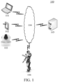
- FIG. 1 is a schematic diagram of an exemplary system architecture that may be applied to an image processing method or an image processing apparatus according to an embodiment of the present disclosure.
- the system architecture 100 may include terminal devices 101 and 102, an image capture device 103, a network 104, a server 105, and a robot 106.
- the image capture device 103 or the terminal device 101 may be configured to capture a first three-dimensional image.
- the network 104 may be configured as a medium to provide a communication link between the terminal device 101 (or 102), the image capture device 103, the server 105, and the robot 106.
- the network 104 may include various connection types, such as a wired or wireless communication link, or a fiber optic cable.
- a user may use the terminal device 101 or 102 to interact with the server 105 through the network 104 to receive or send a message or the like, and the user may also use the image capture device 103 to exchange information with the server 105 or the terminal device 101 or 102 through the network.
- the terminal devices 101 and 102 may be various electronic devices with a display screen and supporting web browsing, including but not limited to smart phones, tablet computers, laptop computers, desktop computers, wearable devices, virtual reality devices, smart homes, and the like.
- the server 105 may be a server that provides various services, for example, a background management server that provides support for an apparatus operated by the user using the terminal device and/or the image capture device 103; or in another example, a background service manager that provides support for a moving operation of the robot.
- the background management server may perform processing such as analysis on data such as a request received from the terminal device or the image capture device, and send a processing result to the robot 106, to control the robot to move.
- the server 105 may, for example, obtain a first three-dimensional image in a three-dimensional coordinate system by using the terminal device 101 (or 102) or the image capture device 103.
- the server 105 may, for example, determine multiple surfaces in the first three-dimensional image, the multiple surfaces each including surface points respectively represented by three-dimensional coordinates.
- the server 105 may, for example, project the surface points of each of the multiple surfaces to a two-dimensional coordinate system, in which a plane extracted from the respective surface is located, to obtain two-dimensional coordinates respectively representing the surface points.
- the server 105 may, for example, determine, for the plane extracted from the respective surface, a polygon and a minimum circumscribed graphic of the polygon according to the two-dimensional coordinates respectively representing the surface points, the minimum circumscribed graphic having a same shape as a first graphic to be recognized.
- the server 105 may, for example, recognize a surface whose area ratio obtained by dividing its corresponding polygon by its corresponding minimum circumscribed graphic is greater than a pre-defined threshold as the first graphic in the first three-dimensional image.
- the server 105 may, for example, control, according to the first graphic, the robot 106 to move.
- the server 105 may be an entity server, or may include a plurality of servers, and any numbers of terminal devices, networks, and servers may be used as actually required.
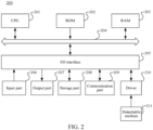
- FIG. 2 is a schematic structural diagram of a computer system 200 applicable to implementing a terminal device according to an embodiment of this application.
- the terminal device shown in FIG. 2 is merely an example, and is not to impose any limitation on a function and use scope of the embodiments of this application.
- the computer system 200 includes a central processing unit (CPU) 201.
- the CPU 201 can perform various appropriate actions and processing according to a program stored in a read-only memory (ROM) 202 or a program loaded into a random access memory (RAM) 203 from a storage part 208.
- the RAM 203 further stores various programs and data required for operations of the system 200.
- the CPU 201, the ROM 202, and the RAM 203 are connected to each other through a bus 204.
- An input/output (I/O) interface 205 is also connected to the bus 204.
- the following components are connected to the I/O interface 205, which include an input part 206 such as a keyboard and a mouse; an output part 207 including a cathode ray tube (CRT), a liquid crystal display (LCD), and a speaker; a storage part 208 including a hard disk; and a communication part 209 including a network interface card such as an LAN card or a modem.
- the communication part 209 performs communication processing by using a network such as the Internet.
- a drive 210 is also connected to the I/O interface 205 as required.
- a removable medium 211 such as a magnetic disk, an optical disc, a magneto-optical disk, or a semiconductor memory, is installed on the drive 210 as required, so that a computer program read from the removable medium is installed into the storage part 208 as required.
- the processes described above with reference to the flowchart may be implemented as a computer software program.
- the embodiments of the present disclosure include a computer program product, including a computer program carried on a computer-readable storage medium.
- the computer program includes program code for performing the methods shown in the flowcharts.
- the computer program may be downloaded and installed through the communication part 209 from a network, and/or installed from the removable medium 211.
- the computer program is executed by the CPU 201, the above functions defined in the system of this application are performed.
- the computer-readable storage medium in this application may be a computer-readable signal medium or a computer-readable storage medium or any combination thereof.
- the computer-readable storage medium may be, for example, but is not limited to, an electric, magnetic, optical, electromagnetic, infrared, or semi-conductive system, apparatus, or component, or any combination of the above.
- a more specific example of the computer-readable storage medium may include, but is not limited to: an electrical connection with one or more wires, a portable computer disk, a hard disk, a random access memory (RAM), a read-only memory (ROM), an erasable programmable read-only memory (EPROM or a flash memory), an optical fiber, a portable compact disc read-only memory (CD-ROM), an optical storage device, a magnetic storage device, or any suitable combination thereof.
- the computer-readable storage medium may be any tangible medium containing or storing a program, and the program may be used by or used in combination with an instruction execution system, an apparatus, or a device.
- a computer-readable signal medium may include a data signal being in a baseband or propagated as a part of a carrier wave, the data signal carrying computer-readable program code.
- a data signal propagated in such a way may assume a plurality of forms, including, but not limited to, an electromagnetic signal, an optical signal, or any appropriate combination thereof.
- the computer-readable signal medium may alternatively be any computer-readable storage medium other than the computer-readable storage medium.
- the computer-readable storage medium may send, propagate, or transmit a program for use by or in combination with an instruction execution system, apparatus, or device.
- the program code contained in the computer-readable storage medium may be transmitted by using any appropriate medium, including but not limited to: a wireless medium, a wire, an optical cable, RF, or any suitable combination thereof.
- each box in a flowchart or a block diagram may represent a module, a program segment, or a part of code.
- the module, the program segment, or the part of code includes one or more executable instructions used for implementing designated logic functions.
- functions annotated in boxes may alternatively occur in a sequence different from that annotated in an accompanying drawing. For example, actually two boxes shown in succession may be performed basically in parallel, and sometimes the two boxes may be performed in a reverse sequence. This is determined by a related function.
- Each box in a block diagram and/or a flowchart and a combination of boxes in the block diagram and/or the flowchart may be implemented by using a dedicated hardware-based system configured to perform a specified function or operation, or may be implemented by using a combination of dedicated hardware and a computer instruction.
- modules and/or units and/or subunits involved in the description of the embodiments of this application may be implemented by software or hardware.
- the described modules and/or units and/or subunits may be disposed in a processor, for example, may be described as follows: a processor includes a sending unit, an obtaining unit, a determining unit, and a first processing unit. Names of the modules and/or units and/or subunits do not constitute a limitation on the modules and/or units and/or subunits in a specific case.
- this application further provides a computer-readable storage medium.
- the computer-readable storage medium may be included in the device described in the foregoing embodiment, or may exist alone without being assembled into the device.
- the computer-readable storage medium carries one or more programs, the one or more programs, when executed by the device, causing the device to implement functions including: obtaining a first three-dimensional image in a three-dimensional coordinate system; determining multiple surfaces in the first three-dimensional image, the multiple surfaces each including surface points respectively represented by three-dimensional coordinates; projecting the surface points of each of the multiple surfaces to a two-dimensional coordinate system, in which a plane extracted from the respective surface is located, to obtain two-dimensional coordinates respectively representing the surface points; determining, for the plane extracted from the respective surface, a polygon and a minimum circumscribed graphic of the polygon according to the two-dimensional coordinates respectively representing the surface points, the minimum circumscribed graphic having a same shape as a first graphic to be recognized; and recognizing a surface whose area ratio obtained by dividing its corresponding polygon by its
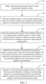
- FIG. 3 is a flowchart of an image processing method according to an exemplary embodiment.
- the method provided in this embodiment of the present disclosure may be processed by any electronic device with a computing processing capability, for example, the server 105 and/or the terminal device 102 or 103 in the embodiment of FIG. 1 .
- the server 105 is an execution body is used as an example for illustration, but the present disclosure is not limited thereto.
- the image processing method provided in this embodiment of the present disclosure includes the following steps.
- the first three-dimensional image may be a three-dimensional image including a to-be-recognized target.
- the to-be-recognized target may be a to-be-recognized object (for example, a plum-blossom pile, a rectangular staircase, or a prism) in the first three-dimensional image, or may be a to-be-recognized graphic (for example, a circular surface of a plum-blossom pile or a rectangular surface of a rectangular staircase) in the first three-dimensional image, or the like, which is not limited in the present disclosure.
- a target scene including the to-be-recognized target may be photographed by using a depth camera, to obtain a depth image of the target scene.
- the depth image may be transformed into a three-dimensional image in the three-dimensional coordinate system according to a pose matrix of the depth camera in the three-dimensional coordinate system, to obtain the first three-dimensional image.
- the depth camera may be an RGB-D camera (for example, a Kinect camera (a three-dimensional somatosensory camera)).
- the three-dimensional coordinate system may be a world coordinate system or the like. This is not limited in the present disclosure.
- the pose matrix of the depth camera may be obtained through simultaneous localization and mapping (SLAM), which is not limited in the present disclosure, either.
- SLAM is a real-time localization and mapping technology, which may be used to obtain in real time a three-dimensional pose of the depth camera in the three-dimensional coordinate system.
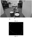
- the depth camera may be first used to perform image capture on a plum-blossom pile on which the legged robot is about to land, to obtain a depth image shown in FIG. 4 , and then the depth image is processed according to a real-time three-dimensional pose of the depth camera, to obtain a first three-dimensional image in the three-dimensional coordinate system.
- S02. Determine multiple surfaces in the first three-dimensional image, the multiple surfaces each including surface points respectively represented by three-dimensional coordinates.
- the depth image shown in FIG. 4 includes a to-be-recognized circular surface 401 or 402, and may further include a table surface, a chair surface, and the like. Therefore, the first three-dimensional image may include the to-be-recognized circular surface, and may also include a recognition interference item such as the table surface or the chair surface.
- the surface may be a plane surface such as a circular plane of a plum-blossom pile or a rectangular plane of a rectangular staircase, or may be a curved surface such as the curved surface of a three-dimensional object.
- all surface graphics (which may be referred to as surfaces) in the first three-dimensional image may be recognized by using a plane fitting technology or a curved surface recognition technology. Then, the surfaces may be screened, to determine a to-be-recognized first graphic from the surfaces.
- a plane surface including points (or points represented by three-dimensional coordinates) with slight depth gradients in a local spatial domain range may be extracted from the depth image (or the three-dimensional image including depth information) by using the plane fitting technology.
- a curved surface of a three-dimensional object may be extracted from the depth image (or the three-dimensional image including depth information) by using the curved surface recognition technology.
- a relatively classical plane fitting method is a region growing segmentation method.
- the region growing segmentation method may include the following steps: dividing the entire depth image (or three-dimensional image including depth information) according to a uniform grid to obtain a plurality of image blocks; fusing image blocks that are adjacent in a spatial domain, and using the fused adjacent image blocks as a new plane to re-solve a plane equation, there being two conditions for whether adjacent image blocks can be fused, a first condition being that a distance between a current image block and a plane equation of its adjacent image block needs to be less than a threshold, and a second condition being that a normal angle between the two adjacent image blocks is less than a threshold; and after a large plane is obtained, performing flood filling by using any point in the plane as a start point to refine a boundary.
- a distance between a neighboring point in the spatial domain and the plane is less than a threshold, it indicates that the point belongs to the current plane.
- a flood filling method is a method of filling a connected region in a specific manner (for example, using a specific color), which achieves different filling effects by setting upper and lower limits for connectable pixels and connection manners.
- the first three-dimensional image may also include the depth information of the image, and plane fitting or curved surface recognition on the depth image may be plane fitting or curved surface recognition on the first three-dimensional image. This is not limited in the present disclosure.
- the plane fitting technology may be used to not only recognize a plane surface from the first three-dimensional image, but also provide a plane equation and a normal direction of the plane surface.
- the curved surface recognition may be used to not only recognize a curved surface from the first three-dimensional image, but also provide a curved surface equation and a normal direction of the curved surface within a local area range. Details are not described in the present disclosure.
- the two-dimensional coordinate system may be constructed according to a plane (in other words, a two-dimensional coordinate system), in which a plane extracted from the respective surface is located.
- a plane in other words, a two-dimensional coordinate system
- the plane extracted from the surface is namely the plane surface itself.
- the plane extracted from the surface may be, for example, a plane region of the curved surface.
- a method of constructing the two-dimensional coordinate system is not limited in the present disclosure.
- the points represented by three-dimensional coordinates in the surface may be projected to the two-dimensional coordinate system, in which a plane extracted from the respective surface is located, to obtain the points, represented by two-dimensional coordinates in the two-dimensional coordinate system, of the surface.
- contour points, represented by three-dimensional coordinates, of the surface may be extracted from the points represented by three-dimensional coordinates, and then the contour points represented by three-dimensional coordinates are mapped to the two-dimensional coordinate system, to obtain two-dimensional coordinates respectively representing the contour points.
- S04. Determine, for the plane extracted from the respective surface, a polygon and a minimum circumscribed graphic of the polygon according to the two-dimensional coordinates respectively representing the surface points, the minimum circumscribed graphic having a same shape as a first graphic to be recognized.
- contours of the surface points respectively represented by two-dimensional coordinates may be connected to generate the polygon.
- contours points represented by two-dimensional coordinates among the surface points respectively represented by two-dimensional coordinates may be directly connected to generate the polygon.
- contour points represented by three-dimensional coordinates in the surface points respectively represented by three-dimensional coordinates may be projected to the two-dimensional coordinate system, to obtain two-dimensional coordinates respectively representing the contour points shown by a dotted line in FIG. 5 ; and positions in the contours points represented by two-dimensional coordinates may be highlighted by using star marks shown in FIG. 5 , and then the stars are connected to obtain the polygon. This is not limited in the present disclosure.
- the minimum circumscribed graphic of the polygon may be further obtained, shapes of the minimum circumscribed graphic and the to-be-recognized first graphic being consistent.
- the to-be-recognized first graphic is a circle
- a circumscribed circle shown in FIG. 6
- the to-be-recognized first graphic is a square
- it may be determined that a circumscribed square of the polygon is used as the minimum circumscribed graphic.
- the to-be-recognized first graphic is a rhombus
- it may be determined that a circumscribed rhombus of the polygon is used as the minimum circumscribed graphic. This is not limited in the present disclosure.
- an area ratio may be obtained by dividing the polygon and the minimum circumscribed graphic. If the area ratio is greater than the pre-defined threshold (for example, 0.8), it may be considered that a surface corresponding to the polygon is a to-be-recognized first graphic in the first three-dimensional image.
- the pre-defined threshold for example, 0.8
- the first graphic may be accurately recognized from the first three-dimensional image, to perform an operation according to the first graphic and the three-dimensional coordinates of the first graphic.
- the first graphic may be a circular surface of a plum-blossom pile on which the legged robot is about to land.
- the legged robot may be controlled to land according to the circular plane and the three-dimensional coordinates of the circular plane.
- the first graphic may be a circular surface of the cylinder.
- the mechanical arm may be controlled to grasp the cylinder according to a position of the circular plane of the cylinder and information (which may be known) such as a height of the cylinder.
- height information of the cylinder may be known in advance. For example, in a situation of grasping a cylindrical ring-pull can in a pipeline, height information of the ring-pull can may be known before the grasping.
- height information of the cylinder may be calculated according to three-dimensional information of the first graphic. For example, assuming that the cylinder stands on a table, the table may be first recognized from the first three-dimensional image and three-dimensional information of the table is obtained. Then, the height information of the cylinder may be determined according to the first graphic and the three-dimensional information of the table.
- FIG. 7 is a flowchart of step S01 in FIG. 3 according to an exemplary embodiment.
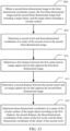
- the first three-dimensional image may be obtained by using a depth image. Referring to FIG. 7 , the following process may be included for obtaining the first three-dimensional image according to the depth image.
- Step S011 Obtain the depth image, the depth image being obtained by using a first image capture device.
- the first image capture device may be a depth camera, and image capture may be performed on a target scene including a to-be-recognized target by using a depth camera, to obtain a depth image of the target scene.
- Step S012 Obtain a pose matrix of the first image capture device in the three-dimensional coordinate system.
- a real-time pose matrix of the depth camera in the three-dimensional coordinate system may be obtained according to SLAM.
- Step S013 Perform coordinate transformation on the depth image according to the pose matrix of the first image capture device, to obtain the first three-dimensional image.
- the depth image may be transformed through matrix transformation to obtain the first three-dimensional image in the three-dimensional coordinate system. Details are not described in the present disclosure.
- the first three-dimensional image including the to-be-recognized object may be accurately obtained by using the depth image including the to-be-recognized object.
- FIG. 8 shows an image processing method according to an exemplary embodiment.
- the minimum circumscribed graphic in this embodiment needs to be a minimum circumscribed circle.
- a center position of the first circle may be further determined.
- the image processing method may include the following steps.
- Step S06 Obtain a first center of the minimum circumscribed circle in the two-dimensional coordinate system.
- Step S07 Map the first center of the minimum circumscribed circle to the three-dimensional coordinate system to obtain three-dimensional coordinates representing the first center, and determine the three-dimensional coordinates representing the first center as three-dimensional coordinates of a center of the first circle.
- the first circle in the first three-dimensional image may not be presented as a complete circle. Therefore, the first circle and a position of the first circle cannot be directly determined in the first three-dimensional image through circle recognition.
- the minimum circumscribed circle serves as a circle image when the first circle is mapped into the two-dimensional coordinate system. Then, three-dimensional coordinates obtained by reversely mapping a center of the minimum circumscribed circle to the three-dimensional coordinate system serve as center coordinates of the first circle.
- Step S08 Determine a first radius of the first circle according to the three-dimensional coordinates of the center of the first circle and three-dimensional coordinates respectively representing contour points of the first circle.
- a distance between each contour point, represented by three-dimensional coordinates, of the first circle and the center of the first circle may be determined by using three-dimensional coordinates of each contour point of the first circle and the three-dimensional coordinates of the center of the first circle, and a maximum distance value may be used as the first radius of the first circle.
- the first center of the minimum circumscribed circle is determined in the two-dimensional coordinate system. Then, the first center is mapped to the three-dimensional coordinate system to obtain the center of the first circle, and the three-dimensional coordinates of the first center in the three-dimensional coordinate system are used as three-dimensional coordinates of the center of the first circle.
- the first radius of the first circle is determined according to the contour points, represented by three-dimensional coordinates, of the first circle and the center of the first circle.
- a first center 9011 of a first circle 901 shown in FIG. 9 may be accurately determined in the first three-dimensional image, and three-dimensional coordinates of the center of the first circle 901 and a first radius of the first circle 901 may be accurately obtained.
- FIG. 10 is a flowchart of step S07 in FIG. 8 according to an exemplary embodiment.
- the first center may not have corresponding three-dimensional coordinates in the three-dimensional coordinate system.
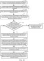
- the points represented by three-dimensional coordinates may be searched by using a flood search algorithm, to determine three-dimensional coordinates corresponding to the first center.
- the following steps may be included for searching the points represented by three-dimensional coordinates by using the flood search algorithm.
- Step S071 Determine, in the surface points respectively represented by three-dimensional coordinates, a start point represented by three-dimensional coordinates.
- the surface points represented by three-dimensional coordinates in the surface may be averaged to obtain a start search point.
- any one of the surface points represented by three-dimensional coordinates in the surface may be selected as a start point represented by three-dimensional coordinates. This is not limited in the present disclosure.
- Step S072 Map the start point represented by three-dimensional coordinates to the two-dimensional coordinate system, to obtain two-dimensional coordinates representing the start point.
- a surface point represented by two-dimensional coordinates and corresponding to the start point represented by three-dimensional coordinates may be directly obtained as the start point represented by two-dimensional coordinates.
- Step S073 Obtain a distance between the first center and the start point represented by two-dimensional coordinates.
- a distance d between the first center and the start point represented by two-dimensional coordinates may be obtained in the two-dimensional coordinate system.
- Step S074 Use a surface point, represented by three-dimensional coordinates, adjacent to the start point represented by three-dimensional coordinates as a search point represented by three-dimensional coordinates, and map the search point represented by three-dimensional coordinates to the two-dimensional coordinate system to obtain two-dimensional representing the search point.
- the surface points represented by three-dimensional coordinates in the first three-dimensional image may be stored in a row-column form.
- the surface point, represented by three-dimensional coordinates, adjacent to the start point represented by three-dimensional coordinates may refer to surface points, represented by three-dimensional coordinates, adjacent to the start point represented by three-dimensional coordinates in storage positions in four directions, including upper, lower, left, and right, or may refer to surface points, represented by three-dimensional coordinates, adjacent to the start point represented by three-dimensional coordinates in storage positions in eight directions, including upper, lower, left, right, upper left, lower left, upper right, and lower right. This is not limited in the present disclosure.
- each search point represented by three-dimensional coordinates may be mapped to the two-dimensional coordinate system, to obtain two-dimensional representing the search point, to perform search according to the search point represented by two-dimensional coordinates.
- Step S075 Determine whether there is at least one search point represented by two-dimensional coordinates and whose distance to the first center is less than the distance between the first center and the start point represented by two-dimensional coordinates.
- a distance between the first center and each search point represented by two-dimensional coordinates may be obtained, and it is determined whether there is at least one search point represented by two-dimensional coordinates and whose distance to the first center is less than the distance between the first center and the start point represented by two-dimensional coordinates.
- Step S076 Determine a search point represented by two-dimensional coordinates and having a minimum distance to the first center in the at least one search point represented by two-dimensional coordinates.
- a search point, represented by two-dimensional coordinates, closest to the first center is used as the search point represented by two-dimensional coordinates, to continue to search the search point represented by two-dimensional coordinates.
- Step S077 Update the distance between the first center and the start point represented by two-dimensional coordinates by using the distance between the first center and the determined search point represented by two-dimensional coordinates, and update the start point represented by three-dimensional coordinates by using a surface point represented by three-dimensional coordinates and corresponding to the determined search point represented by two-dimensional coordinates.
- d may be made equal to d', to update the distance between the first center and the start point represented by two-dimensional coordinates.
- Step S078 Map the updated start point represented by three-dimensional coordinates to the two-dimensional coordinate system, to update the start point represented by two-dimensional coordinates.
- Step S079 Update the search point represented by three-dimensional coordinates by using a surface point, represented by three-dimensional coordinates, adjacent to the updated start point represented by three-dimensional coordinates, and map the updated search point represented by three-dimensional coordinates to the two-dimensional coordinate system to update the search point represented by two-dimensional coordinates.
- a surface point, represented by three-dimensional coordinates, adjacent to the start point represented by three-dimensional coordinates may be further obtained in the first three-dimensional image to update the search point represented by three-dimensional coordinates.
- the updated search point represented by three-dimensional coordinates further needs to be mapped to the two-dimensional coordinate system to update the search point represented by two-dimensional coordinates, and search continues to be performed according to step S075 to step S0710, until a distance between each current search point represented by two-dimensional coordinates and the first center is greater than a current distance between the first center and the start point represented by two-dimensional coordinates, and step S0710 is performed.
- Step S0710 Use the three-dimensional coordinates representing the start point as the three-dimensional coordinates representing the first center.
- FIG. 11 is a schematic diagram of completing coordinate search according to a search point represented by two-dimensional coordinates in a minimum circumscribed circle according to an exemplary embodiment.
- a solid circular represents a search point represented by two-dimensional coordinates
- a hollow circular point represents a search point, represented by two-dimensional coordinates, at which search is stopped
- a path represented by a solid arrow may represent a valid search path (that is, search points, represented by two-dimensional coordinates, on the path are gradually close to a first center 111, and two-dimensional coordinates close to the first center may be found by using the path)
- a path represented by a dashed arrow may represent an invalid search path (that is, search points, represented by two-dimensional coordinates, on the path are gradually away from the first center, and search on the path is stopped).
- FIG. 11 in a minimum circumscribed circle 110, a solid circular represents a search point represented by two-dimensional coordinates
- a hollow circular point represents a search point, represented by two-dimensional coordinates, at which search is stopped
- a path represented by a solid arrow may represent a valid search path (that is, search points, represented by two-dimensional coordinates, on
- search points represented by two-dimensional coordinates in the two-dimensional coordinate system may be controlled to be gradually close to the first center 111, so that search points, represented by three-dimensional coordinates, corresponding to the search points represented by two-dimensional coordinates are gradually close to the center of the first circle, to obtain the three-dimensional coordinates of the center of the first circle.
- the search point represented by three-dimensional coordinates in the three-dimensional coordinate system is mapped to the two-dimensional coordinate system, to obtain the two-dimensional search point, thereby implementing a mapping between the search point represented by two-dimensional coordinates and the search point represented by three-dimensional coordinates.
- the search points represented by two-dimensional coordinates are controlled to be gradually close to the first center, so that the search point represented by three-dimensional coordinates in the three-dimensional coordinate system are gradually close to the center of the first circle, to obtain the three-dimensional coordinates of the center of the first circle.
- a mapping relationship between the search point represented by three-dimensional coordinates and the search point represented by two-dimensional coordinates is constructed through transformation of the surface point represented by three-dimensional coordinates between the three-dimensional coordinate system and the two-dimensional coordinate system, the point represented by two-dimensional coordinates and being closest to the first center is determined by searching for the search point represented by two-dimensional coordinates in the two-dimensional coordinate system, and the point represented by two-dimensional coordinates and being closest to the first center is mapped to the three-dimensional coordinate system to obtain the three-dimensional coordinates of the center of the first circle.
- the three-dimensional coordinates determined through flood search may be used as the three-dimensional coordinates of a mapped point obtained by mapping the first center of the minimum circumscribed circle to the three-dimensional coordinate system. Then, a distance between the mapped point and each contour point, represented by three-dimensional coordinates, of the first circle is obtained, and a maximum distance is used as the first radius of the first circle.
- the three-dimensional coordinates representing the mapped point are used as the three-dimensional coordinates representing the first center in the three-dimensional coordinate system in a case that a distance between each contour point, represented by three-dimensional coordinates, of the first circle and the mapped point falls within a pre-defined range.
- a first circle with a first radius value greater than the pre-defined range may be filtered out.
- FIG. 12 shows a method of mapping a first center to a three-dimensional coordinate system according to an exemplary embodiment. Referring to FIG. 12 , the method may include the following steps.
- Step S121 Determine, in the surface points respectively represented by three-dimensional coordinates, a start point represented by three-dimensional coordinates.
- Step S122 Map the start point represented by three-dimensional coordinates to the two-dimensional coordinate system, to obtain two-dimensional coordinates representing the start point.
- the start point represented by three-dimensional coordinates may be mapped to the two-dimensional coordinate system, to obtain two-dimensional coordinates representing the start point 112 shown in FIG. 11 .
- Step S123 Obtain a distance between the first center and the start point represented by two-dimensional coordinates.
- a distance d between the start point 112 represented by two-dimensional coordinates and the first center 111 in FIG. 11 may be obtained.
- Step S124 Use a surface point, represented by three-dimensional coordinates, adjacent to the start point represented by three-dimensional coordinates as a search point represented by three-dimensional coordinates, and map the search point represented by three-dimensional coordinates to the two-dimensional coordinate system to obtain two-dimensional representing the search point.
- a search point 113 represented by two-dimensional coordinates shown in FIG. 11 may be obtained by mapping the search point represented by three-dimensional coordinates to the two-dimensional coordinate system. It is to be understood that more than one point represented by three-dimensional coordinates may be adjacent to the start point represented by three-dimensional coordinates.
- a distance d' between the search point 113 represented by two-dimensional coordinates and the first center 11 may be obtained.
- Step S125 Determine whether there is a search point represented by two-dimensional coordinates and whose distance to the first center is less than the distance between the first center and the start point represented by two-dimensional coordinates, the search point represented by two-dimensional coordinates being corresponding to a search point represented by three-dimensional coordinates.
- step S126 if in search points represented by two-dimensional coordinates there is a search point represented by two-dimensional coordinates and whose distance to the first center is less than the distance between the first center and the start point represented by two-dimensional coordinates, step S126 continues to be performed.
- step S126 needs to be performed to continue to perform search on a search point represented by three-dimensional coordinates and corresponding to the search point 113 represented by two-dimensional coordinates.
- Step S126 Determine whether there is a pixel adjacent to the search point, represented by three-dimensional coordinates, in the surface points respectively represented by three-dimensional coordinates.
- step S127 it is determined whether there is a point, represented by three-dimensional coordinates, adjacent to the current search point represented by three-dimensional coordinates in the surface. If there is still a point, represented by three-dimensional coordinates, adjacent to the current search point represented by three-dimensional coordinates in the surface, step S127 continues to be performed.
- Step S127 Update the start point represented by three-dimensional coordinates by using the search point represented by three-dimensional coordinates.
- the current search point represented by three-dimensional coordinates may be used as a start point represented by three-dimensional coordinates, and the updated start point represented by three-dimensional coordinates may be mapped to the two-dimensional coordinate system to obtain the start point 113 represented by two-dimensional coordinates.
- steps S122 to S126 continue to be performed, until it is determined in step S125 that in the search points represented by two-dimensional coordinates, there is no search point represented by two-dimensional coordinates and whose distance to the first center is less than a current distance between the first center and the start point represented by two-dimensional coordinates, or it is determined in step S126 that in the surface points respectively represented by three-dimensional coordinates, there is no pixel adjacent to the search point represented by three-dimensional coordinates, and step S 128 continues to be performed.
- Step S128 Use the three-dimensional coordinates representing the start point as the three-dimensional coordinates representing the first center.
- a mapping relationship between the search point represented by three-dimensional coordinates and the search point represented by two-dimensional coordinates is constructed through transformation of the point represented by three-dimensional coordinates between the three-dimensional coordinate system and the two-dimensional coordinate system, the point represented by two-dimensional coordinates and being closest to the first center is determined by searching for the search point represented by two-dimensional coordinates in the two-dimensional coordinate system, and the point, represented by two-dimensional coordinates, closest to the first center is mapped to the three-dimensional coordinate system to obtain the three-dimensional coordinates of the center of the first circle.
- FIG. 13 shows an image processing method according to an exemplary embodiment.
- depth data of image capture is usually limited by working distances, including a shortest working distance and a longest working distance. Depth information beyond the working distances is unreliable and is usually filtered out directly. However, within an effective working distance range, depth information is related to a distance, that is, an object being closer to the camera indicates more accurate depth information to be obtained, and a center and a radius of a circular surface extracted within a closer distance range are more accurate.
- the image processing method may include the following steps.
- Step S08 Obtain a second three-dimensional image in the three-dimensional coordinate system, the first three-dimensional image and the second three-dimensional image both including a target object, and the target object including a circular surface.
- the target object may be a to-be-recognized cylinder or the like, or the target object may include a to-be-recognized circular plane.
- a first depth image capture device and a second depth image capture device may be used to perform image capture on the circular surface of the target object respectively.
- the first depth image capture device and the second depth image capture device may be the same device or different devices, which is not limited in the present disclosure.
- Step S09 Determine a second circle and three-dimensional coordinates of a center of the second circle in the second three-dimensional image.
- the first circle and the three-dimensional coordinates of the center of the first circle may be determined from the first three-dimensional image by using the image processing method provided in the present disclosure.
- the second circle and the three-dimensional coordinates of the center of the second circle may be determined from the second three-dimensional image by using the image processing method provided in the present disclosure.
- Step S10 Determine a first distance between the first center and an image capture device that captures the first three-dimensional image.
- Step S11 Determine a second distance between the second center and an image capture device that captures the second three-dimensional image.
- the first distance and the second distance may be distances determined in the same coordinate system (for example, the three-dimensional coordinate system).
- Step S12 Determine three-dimensional coordinates of a center of the circular surface of the target object according to the first distance, the second distance, the three-dimensional coordinates of the center of the first circle, and the three-dimensional coordinates of the center of the second circle.
- the first distance di may be processed according to formula (1) to determine a first weight wi of the three-dimensional coordinates of the center of the first circle
- the second distance d 2 may be further processed according to formula (1) to determine a first weight w 2 of the three-dimensional coordinates of the center of the second circle
- the three-dimensional coordinates of the center of the circular surface of the target object may be accurately determined.
- FIG. 14 shows an image processing method according to an exemplary embodiment.
- the image processing method may include the following steps.
- Step S13 Determine the first radius of the first circle and a second radius of the second circle.
- Step S14 Determine a radius of the circular surface according to the first distance, the second distance, the first radius, and the second radius.
- the first radius r1 of the first circle and the second radius r2 of the second circle may be respectively used as c 1 and c 2 in formula (2), and then the radius of the circular surface may be accurately determined according to formula (2).
- a method that may be used to accurately determine a radius of a surface is provided.
- FIG. 15 shows an image processing method according to an exemplary embodiment.
- the image processing method may include the following steps.
- Step S 1 Determine a normal of the first circle.
- a plane equation of each surface may be obtained during plane fitting on the first three-dimensional image.
- the first circle is selected from the surfaces. Therefore, a normal direction of the first circle may be directly obtained according to the plane equation of the surface.
- Step S2 Determine the first radius of the first circle according to contour points, respectively represented by three-dimensional coordinates, of the first circle and the first center.
- distances between the first center of the first circle and the contour points, represented by three-dimensional coordinates, of the first circle may be obtained, and a maximum distance value is used as the first radius of the first circle.
- Step S3 Generate control information according to the three-dimensional coordinates of the center, the first radius, and the normal of the first circle, the control information being used for controlling a center of a foot of a robot to coincide with the three-dimensional coordinates of the center of the first circle.
- the first circle may be a circular surface of a plum-blossom pile on which a legged robot is about to land.
- the robot may be controlled to land at the center position of the first circle along the normal direction, thereby controlling the robot to move.
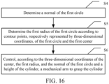
- FIG. 16 shows an image processing method according to an exemplary embodiment.
- the first three-dimensional image is captured from a circular surface of a cylinder.
- the image processing method may include the following steps.
- Step S4 Determine a normal of the first circle.
- Step S5 Determine the first radius of the first circle according to contour points, respectively represented by three-dimensional coordinates, of the first circle and the first center.
- distances between the first center of the first circle and the contour points, represented by three-dimensional coordinates, of the first circle may be obtained, and a maximum distance value is used as the first radius of the first circle.
- Step S6 Control, according to the three-dimensional coordinates of the center, the first radius, and the normal of the first circle and a height of the cylinder, a mechanical arm to grasp the cylinder.
- the cylinder may be a cylinder that the mechanical arm needs to grasp.
- height information of the cylinder may be known in advance. For example, in a situation of grasping a cylindrical ring-pull can in a pipeline, height information of the ring-pull can may be known.
- height information of the cylinder may be calculated according to three-dimensional information of the first graphic. For example, assuming that the cylinder stands on a table, the table may be first recognized from the first three-dimensional image and three-dimensional information of the table is obtained. Then, the height information of the cylinder may be determined according to the first graphic and the three-dimensional information of the table.
- the mechanical arm may be controlled to grasp the cylinder.
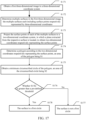
- FIG. 17 shows an image processing method according to an exemplary embodiment.
- the image processing method may include the following steps.
- Step S171 Obtain a first three-dimensional image in a three-dimensional coordinate system.
- Step S172 Determine multiple surfaces in the first three-dimensional image, the multiple surfaces each including surface points respectively represented by three-dimensional coordinates.
- Step S173 Project the surface points of each of the multiple surfaces to a two-dimensional coordinate system, in which a plane extracted from the respective surface is located, to obtain two-dimensional coordinates respectively representing the surface points.
- Step S174 Determine a polygon according to the two-dimensional coordinates respectively representing the surface points, an area of the polygon being S 1.
- Step S175 Obtain a minimum circumscribed circle of the polygon, an area of the circumscribed circle being S2.
- Step S176 Determine whether S1/S2 is greater than a pre-defined threshold.
- step S177 is performed. If S1/S2 is less than or equal to the pre-defined threshold, step S 178 is performed.
- Step S177 The surface is not a first circle.
- Step S178 The surface is a first circle.
- the first graphic may be accurately recognized from the first three-dimensional image, to perform an operation according to the first graphic and the three-dimensional coordinates of the first graphic.
- the first graphic may be a circular surface of a plum-blossom pile on which the legged robot is about to land.
- the legged robot may be controlled to land according to the circular plane and the three-dimensional coordinates of the circular plane.
- the first graphic may be a circular surface of the cylinder.
- the mechanical arm may be controlled to grasp the cylinder according to a position of the circular plane of the cylinder and information such as a length (or height) of the cylinder.
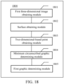
- FIG. 18 is a block diagram of an image processing apparatus according to an exemplary embodiment.
- the image processing apparatus 1800 provided in this embodiment of the present disclosure may include: a first three-dimensional image obtaining module 1801, a surface obtaining module 1802, a two-dimensional-based point obtaining module 1803, a minimum circumscribed graphic determining module 1804, and a first graphic determining module 1805.
- the first three-dimensional image obtaining module 1801 may be configured to obtain a first three-dimensional image in a three-dimensional coordinate system.
- the surface obtaining module 1802 may be configured to determine multiple surfaces in the first three-dimensional image, the multiple surfaces each including surface points respectively represented by three-dimensional coordinates.
- the two-dimensional-based point obtaining module 1803 may be configured to project the surface points of each of the multiple surfaces to a two-dimensional coordinate system, in which a plane extracted from the respective surface is located, to obtain two-dimensional coordinates respectively representing the surface points.
- the minimum circumscribed graphic determining module 1804 may be configured to determine, for the plane extracted from the respective surface, a polygon and a minimum circumscribed graphic of the polygon according to the two-dimensional coordinates respectively representing the surface points, the minimum circumscribed graphic having a same shape as a first graphic to be recognized.
- the first graphic determining module 1805 may be configured to recognize a surface whose area ratio obtained by dividing its corresponding polygon by its corresponding minimum circumscribed graphic is greater than a pre-defined threshold as the first graphic in the first three-dimensional image.
- the minimum circumscribed graphic is a minimum circumscribed circle
- the first graphic is a first circle
- the image processing apparatus 1800 may include: a first center obtaining unit and a first center coordinate obtaining unit.
- the first center obtaining unit may be configured to obtain a first center of the minimum circumscribed circle in the two-dimensional coordinate system.
- the first center coordinate obtaining unit may be configured to map the first center of the minimum circumscribed circle to the three-dimensional coordinate system to obtain three-dimensional coordinates representing the first center, and determine the three-dimensional coordinates representing the first center as three-dimensional coordinates of a center of the first circle; and determine a first radius of the first circle according to the three-dimensional coordinates of the center of the first circle and three-dimensional coordinates respectively representing contour points of the first circle.
- the first center coordinate obtaining unit may include: a three-dimensional-based start point obtaining subunit, a two-dimensional-based start point obtaining subunit, a distance obtaining subunit, a two-dimensional-based search point obtaining subunit, and a coordinate obtaining subunit.
- the three-dimensional-based start point obtaining subunit may be configured to determine, in the surface points respectively represented by three-dimensional coordinates, a start point represented by three-dimensional coordinates.
- the two-dimensional-based start point obtaining subunit may be configured to map the start point represented by three-dimensional coordinates to the two-dimensional coordinate system, to obtain two-dimensional coordinates representing the start point.
- the distance obtaining subunit may be configured to obtain a distance between the first center and the start point represented by two-dimensional coordinates.
- the two-dimensional-based search point obtaining subunit may be configured to use a surface point, represented by three-dimensional coordinates, adjacent to the start point represented by three-dimensional coordinates as a search point represented by three-dimensional coordinates, and map the search point represented by three-dimensional coordinates to the two-dimensional coordinate system to obtain two-dimensional representing the search point.
- the coordinate obtaining subunit may be configured to use the three-dimensional coordinates representing the start point as the three-dimensional coordinates representing the first center in a case that a distance between the first center and each search point represented by two-dimensional coordinates is greater than or equal to the distance between the first center and the start point represented by two-dimensional coordinates.
- the first center coordinate obtaining unit may further include: a two-dimensional-based search point obtaining subunit, a three-dimensional-based start point update subunit, two-dimensional-based start point update subunit, and a three-dimensional-based search point update subunit.
- the two-dimensional-based search point obtaining subunit may be configured to determine, in a case that there is at least one search point represented by two-dimensional coordinates and whose distance to the first center is less than the distance between the first center and the start point represented by two-dimensional coordinates, a search point represented by two-dimensional coordinates and having a minimum distance to the first center in the at least one search point represented by two-dimensional coordinates.
- the three-dimensional-based start point update subunit may be configured to update the distance between the first center and the start point represented by two-dimensional coordinates by using the distance between the first center and the determined search point represented by two-dimensional coordinates, and update the start point represented by three-dimensional coordinates by using a surface point represented by three-dimensional coordinates and corresponding to the determined search point represented by two-dimensional coordinates.
- the two-dimensional-based start point update subunit may be configured to map the updated start point represented by three-dimensional coordinates to the two-dimensional coordinate system, to update the start point represented by two-dimensional coordinates.
- the search point represented by three-dimensional coordinates update subunit may be configured to update the search point represented by three-dimensional coordinates by using a surface point, represented by three-dimensional coordinates, adjacent to the updated start point represented by three-dimensional coordinates, and map the updated search point represented by three-dimensional coordinates to the two-dimensional coordinate system to update the search point represented by two-dimensional coordinates.
- the two-dimensional-based point obtaining module 1803 may include: a three-dimensional-based contour point determining unit and a two-dimensional-based contour point determining unit.
- the three-dimensional-based contour point determining unit may be configured to determine contour points, represented by three-dimensional coordinates, of each of the multiple surfaces in the surfaces points of the respective surface.
- the two-dimensional-based contour point determining unit may be configured to project the contour points represented by three-dimensional coordinates to the two-dimensional coordinate system, to obtain two-dimensional coordinates respectively representing the contour points, so as to determine the polygon according to the contour points represented by two-dimensional coordinates.
- the image processing apparatus may further include: a second three-dimensional image obtaining module, a second circle obtaining module, a first distance determining module, a second distance determining module, and a center coordinate determining module.
- the second three-dimensional image obtaining module may be configured to obtain a second three-dimensional image in the three-dimensional coordinate system, the first three-dimensional image and the second three-dimensional image both including a target object, and the target object including a circular surface.
- the second circle obtaining module may be configured to determine a second circle and three-dimensional coordinates of a center of the second circle in the second three-dimensional image.
- the first distance determining module may be configured to determine a first distance between the first center and an image capture device that captures the first three-dimensional image.
- the second distance determining module may be configured to determine a second distance between the second center and an image capture device that captures the second three-dimensional image.
- the center coordinate determining module may be configured to determine three-dimensional coordinates of a center of the circular surface of the target object according to the first distance, the second distance, the three-dimensional coordinates of the center of the first circle, and the three-dimensional coordinates of the center of the second circle.
- the image processing apparatus may further include: a radius obtaining module and a radius determining module.
- the radius obtaining module may be configured to determine the first radius of the first circle and a second radius of the second circle.
- the radius determining module may be configured to determine a radius of the circular surface according to the first distance, the second distance, the first radius, and the second radius.
- the first center coordinate obtaining unit may include: a mapped point obtaining unit, a distance obtaining subunit, and a coordinate obtaining subunit.
- the mapped point obtaining unit may be configured to map the first center of the minimum circumscribed circle to the three-dimensional coordinate system, to obtain a mapped point and three-dimensional coordinates representing the mapped point.
- the distance obtaining subunit may be configured to obtain a distance between the mapped point and each contour point, represented by three-dimensional coordinates, of the first circle.
- the coordinate obtaining subunit may be configured to use the three-dimensional coordinates representing the mapped point as the three-dimensional coordinates representing the first center in the three-dimensional coordinate system in a case that a distance between each contour point, represented by three-dimensional coordinates, of the first circle and the mapped point falls within a pre-defined range.
- the image processing apparatus may further include: a first normal determining module, a first radius obtaining module, and a robot control module.
- the first normal determining module may be configured to determine a normal of the first circle.
- the first radius obtaining module may be configured to determine the first radius of the first circle according to contour points, respectively represented by three-dimensional coordinates, of the first circle and the first center.
- the robot control module may be configured to generate control information according to the three-dimensional coordinates of the center, the first radius, and the normal of the first circle, the control information being used for controlling a center of a foot of a robot to coincide with the three-dimensional coordinates of the center of the first circle.
- the first three-dimensional image is captured from a circular surface of a cylinder.
- the image processing apparatus may include: a second normal determining module, a second radius obtaining module, and a mechanical arm control module.
- the second normal determining module may be configured to determine a normal of the first circle.
- the second radius determining module may be configured to determine the first radius of the first circle according to contour points, respectively represented by three-dimensional coordinates, of the first circle and the first center.
- the mechanical arm control module may be configured to control, according to the three-dimensional coordinates of the center, the first radius, and the normal of the first circle and a height of the cylinder, a mechanical arm to grasp the cylinder.
- the first three-dimensional image is obtained by using a depth image.
- the first three-dimensional image obtaining module 1801 may include: a depth image obtaining unit, a pose matrix obtaining unit, and a first three-dimensional image obtaining unit.
- the depth image obtaining unit may be configured to obtain the depth image, the depth image being obtained by using a first image capture device.
- the pose matrix obtaining unit may be configured to obtain a pose matrix of the first image capture device in the three-dimensional coordinate system.
- the first three-dimensional image obtaining unit may be configured to perform coordinate transformation on the depth image according to the pose matrix of the first image capture device, to obtain the first three-dimensional image.
- the non-volatile memory may include a read-only memory (ROM), a programmable ROM (PROM), an electrically programmable ROM (EPROM), an electrically erasable programmable ROM (EEPROM), or a flash memory.
- ROM read-only memory
- PROM programmable ROM
- EPROM electrically programmable ROM
- EEPROM electrically erasable programmable ROM
- flash memory a flash memory.
- the volatile memory may include a random access memory (RAM) or an external cache.
- the RAM is available in a number of forms, such as a static RAM (SRAM), a dynamic RAM (DRAM), a synchronous DRAM (SDRAM), a double data rate SDRAM (DDRSDRAM), an enhanced SDRAM (ESDRAM), a synchronous link (Synchlink) DRAM (SLDRAM), a RAM bus (Rambus) direct RAM (RDRAM), a direct Rambus dynamic RAM (DRDRAM), and a Rambus dynamic RAM (RDRAM).
- SRAM static RAM
- DRAM dynamic RAM
- SDRAM synchronous DRAM
- DDRSDRAM double data rate SDRAM
- ESDRAM enhanced SDRAM
- SLDRAM synchronous link
- RAM bus Rabus direct RAM
- DRDRAM direct Rambus dynamic RAM
- RDRAM Rambus dynamic RAM
Landscapes
- Engineering & Computer Science (AREA)
- Physics & Mathematics (AREA)
- General Physics & Mathematics (AREA)
- Theoretical Computer Science (AREA)
- Multimedia (AREA)
- Computer Vision & Pattern Recognition (AREA)
- Software Systems (AREA)
- Geometry (AREA)
- Image Processing (AREA)
- Image Analysis (AREA)
Abstract
Description
- This application claims priority to
Chinese Patent Application No. 2020108259363, filed with China National Intellectual Property Administration on August 17, 2020 - The present disclosure relates to the field of image processing technologies, and in particular, to an image processing method and apparatus, an electronic device, and a computer-readable storage medium.
- Target recognition and localization are very important basic research in the field of artificial intelligence and machine vision, whose research goal is to perceive an environment and recognize an object in the environment by using image information, video information, or spatial information, for example, perform image capture and recognition on a to-be-grasped cylinder in a target pipeline, so that a mechanical arm can grasp the cylinder; or in another example, perform image capture and recognition on a circular plum-blossom pile on which a legged robot is about to land, to control a foothold of the legged robot during movement of the legged robot.
- In the related art, a to-be-recognized target may not be accurately recognized due to an angle of image capture, a color of the photographed target, or the like.
- According to embodiments of this application, an image processing method and apparatus, an electronic device, and a computer-readable storage medium are provided.
- An image processing method is provided. The method includes: obtaining a first three-dimensional image in a three-dimensional coordinate system; determining multiple surfaces in the first three-dimensional image, the multiple surfaces each including surface points respectively represented by three-dimensional coordinates; projecting the surface points of each of the multiple surfaces to a two-dimensional coordinate system, in which a plane extracted from the respective surface is located, to obtain two-dimensional coordinates respectively representing the surface points; determining, for the plane extracted from the respective surface, a polygon and a minimum circumscribed graphic of the polygon according to the two-dimensional coordinates respectively representing the surface points, the minimum circumscribed graphic having a same shape as a first graphic to be recognized; and recognizing a surface whose area ratio obtained by dividing its corresponding polygon by its corresponding minimum circumscribed graphic is greater than a pre-defined threshold as the first graphic in the first three-dimensional image.
- An image processing apparatus is provided. The image processing apparatus includes: a first three-dimensional image obtaining module, a surface obtaining module, a two-dimensional-based point obtaining module, a minimum circumscribed graphic determining module, and a first graphic determining module.
- The first three-dimensional image obtaining module may be configured to obtain a first three-dimensional image in a three-dimensional coordinate system. The surface obtaining module may be configured to determine multiple surfaces in the first three-dimensional image, the multiple surfaces each including surface points respectively represented by three-dimensional coordinates. The two-dimensional-based point obtaining module may be configured to project the surface points of each of the multiple surfaces to a two-dimensional coordinate system, in which a plane extracted from the respective surface is located, to obtain two-dimensional coordinates respectively representing the surface points. The minimum circumscribed graphic determining module may be configured to determine, for the plane extracted from the respective surface, a polygon and a minimum circumscribed graphic of the polygon according to the two-dimensional coordinates respectively representing the surface points, the minimum circumscribed graphic having a same shape as a first graphic to be recognized. The first graphic determining module may be configured to recognize a surface whose area ratio obtained by dividing its corresponding polygon by its corresponding minimum circumscribed graphic is greater than a pre-defined threshold as the first graphic in the first three-dimensional image.
- In some embodiments, the minimum circumscribed graphic is a minimum circumscribed circle, and the first graphic is a first circle.
- In some embodiments, the image processing apparatus may include: a first center obtaining unit and a first center coordinate obtaining unit.
- The first center obtaining unit may be configured to obtain a first center of the minimum circumscribed circle in the two-dimensional coordinate system. The first center coordinate obtaining unit may be configured to map the first center of the minimum circumscribed circle to the three-dimensional coordinate system to obtain three-dimensional coordinates representing the first center, and determine the three-dimensional coordinates representing the first center as three-dimensional coordinates of a center of the first circle; and determine a first radius of the first circle according to the three-dimensional coordinates of the center of the first circle and three-dimensional coordinates respectively representing contour points of the first circle.
- In some embodiments, the first center coordinate obtaining unit may include: a three-dimensional-based start point obtaining subunit, a two-dimensional-based start point obtaining subunit, a distance obtaining subunit, a two-dimensional-based search point obtaining subunit, and a coordinate obtaining subunit.
- The three-dimensional-based start point obtaining subunit may be configured to determine, in the surface points respectively represented by three-dimensional coordinates, a start point represented by three-dimensional coordinates. The two-dimensional-based start point obtaining subunit may be configured to map the start point represented by three-dimensional coordinates to the two-dimensional coordinate system, to obtain two-dimensional coordinates representing the start point. The distance obtaining subunit may be configured to obtain a distance between the first center and the start point represented by two-dimensional coordinates. The two-dimensional-based search point obtaining subunit may be configured to use a surface point, represented by three-dimensional coordinates, adjacent to the start point represented by three-dimensional coordinates as a search point represented by three-dimensional coordinates, and map the search point represented by three-dimensional coordinates to the two-dimensional coordinate system to obtain two-dimensional representing the search point. The coordinate obtaining subunit may be configured to use the three-dimensional coordinates representing the start point as the three-dimensional coordinates representing the first center in a case that a distance between the first center and each search point represented by two-dimensional coordinates is greater than or equal to the distance between the first center and the start point represented by two-dimensional coordinates.
- In some embodiments, the first center coordinate obtaining unit may further include: a two-dimensional-based search point obtaining subunit, a three-dimensional-based start point update subunit, two-dimensional-based start point update subunit, and a three-dimensional-based search point update subunit.
- The two-dimensional-based search point obtaining subunit may be configured to determine, in a case that there is at least one search point represented by two-dimensional coordinates and whose distance to the first center is less than the distance between the first center and the start point represented by two-dimensional coordinates, a search point represented by two-dimensional coordinates and having a minimum distance to the first center in the at least one search point represented by two-dimensional coordinates. The three-dimensional-based start point update subunit may be configured to update the distance between the first center and the start point represented by two-dimensional coordinates by using the distance between the first center and the determined search point represented by two-dimensional coordinates, and update the start point represented by three-dimensional coordinates by using a surface point represented by three-dimensional coordinates and corresponding to the determined search point represented by two-dimensional coordinates. The two-dimensional-based start point update subunit may be configured to map the updated start point represented by three-dimensional coordinates to the two-dimensional coordinate system, to update the start point represented by two-dimensional coordinates. The search point represented by three-dimensional coordinates update subunit may be configured to update the search point represented by three-dimensional coordinates by using a surface point, represented by three-dimensional coordinates, adjacent to the updated start point represented by three-dimensional coordinates, and map the updated search point represented by three-dimensional coordinates to the two-dimensional coordinate system to update the search point represented by two-dimensional coordinates.
- In some embodiments, the two-dimensional-based point obtaining module may include: a three-dimensional-based contour point determining unit and a two-dimensional-based contour point determining unit.
- The three-dimensional-based contour point determining unit may be configured to determine contour points, represented by three-dimensional coordinates, of each of the multiple surfaces in the surfaces points of the respective surface. The two-dimensional-based contour point determining unit may be configured to project the contour points represented by three-dimensional coordinates to the two-dimensional coordinate system, to obtain two-dimensional coordinates respectively representing the contour points, so as to determine the polygon according to the contour points represented by two-dimensional coordinates.
- In some embodiments, the image processing apparatus may further include: a second three-dimensional image obtaining module, a second circle obtaining module, a first distance determining module, a second distance determining module, and a center coordinate determining module.
- The second three-dimensional image obtaining module may be configured to obtain a second three-dimensional image in the three-dimensional coordinate system, the first three-dimensional image and the second three-dimensional image both including a target object, and the target object including a circular surface. The second circle obtaining module may be configured to determine a second circle and three-dimensional coordinates of a center of the second circle in the second three-dimensional image. The first distance determining module may be configured to determine a first distance between the first center and an image capture device that captures the first three-dimensional image. The second distance determining module may be configured to determine a second distance between the second center and an image capture device that captures the second three-dimensional image. The center coordinate determining module may be configured to determine three-dimensional coordinates of a center of the circular surface of the target object according to the first distance, the second distance, the three-dimensional coordinates of the center of the first circle, and the three-dimensional coordinates of the center of the second circle.
- In some embodiments, the image processing apparatus may further include: a radius obtaining module and a radius determining module.
- The radius obtaining module may be configured to determine the first radius of the first circle and a second radius of the second circle. The radius determining module may be configured to determine a radius of the circular surface according to the first distance, the second distance, the first radius, and the second radius.
- In some embodiments, the first center coordinate obtaining unit may include: a mapped point obtaining unit, a distance obtaining subunit, and a coordinate obtaining subunit.
- The mapped point obtaining unit may be configured to map the first center of the minimum circumscribed circle to the three-dimensional coordinate system, to obtain a mapped point and three-dimensional coordinates representing the mapped point. The distance obtaining subunit may be configured to obtain a distance between the mapped point and each contour point, represented by three-dimensional coordinates, of the first circle. The coordinate obtaining subunit may be configured to use the three-dimensional coordinates representing the mapped point as the three-dimensional coordinates representing the first center in the three-dimensional coordinate system in a case that a distance between each contour point, represented by three-dimensional coordinates, of the first circle and the mapped point falls within a pre-defined range.
- In some embodiments, the image processing apparatus may further include: a first normal determining module, a first radius obtaining module, and a robot control module.
- The first normal determining module may be configured to determine a normal of the first circle. The first radius obtaining module may be configured to determine the first radius of the first circle according to contour points, respectively represented by three-dimensional coordinates, of the first circle and the first center. The robot control module may be configured to generate control information according to the three-dimensional coordinates of the center, the first radius, and the normal of the first circle, the control information being used for controlling a center of a foot of a robot to coincide with the three-dimensional coordinates of the center of the first circle.
- In some embodiments, the first three-dimensional image is captured from a circular surface of a cylinder.
- In some embodiments, the image processing apparatus may include: a second normal determining module, a second radius obtaining module, and a mechanical arm control module.
- The second normal determining module may be configured to determine a normal of the first circle. The second radius obtaining module may be configured to determine the first radius of the first circle according to contour points, respectively represented by three-dimensional coordinates, of the first circle and the first center. The mechanical arm control module may be configured to control, according to the three-dimensional coordinates of the center, the first radius, and the normal of the first circle and a height of the cylinder, a mechanical arm to grasp the cylinder.
- In some embodiments, the first three-dimensional image is obtained by using a depth image.
- In some embodiments, the first three-dimensional image obtaining module may include: a depth image obtaining unit, a pose matrix obtaining unit, and a first three-dimensional image obtaining unit.
- The depth image obtaining unit may be configured to obtain the depth image, the depth image being obtained by using a first image capture device. The pose matrix obtaining unit may be configured to obtain a pose matrix of the first image capture device in the three-dimensional coordinate system. The first three-dimensional image obtaining unit may be configured to perform coordinate transformation on the depth image according to the pose matrix of the first image capture device, to obtain the first three-dimensional image.
- An electronic device is provided. The electronic device includes: one or more processors; and a storage apparatus, configured to store one or more programs, the one or more programs, when executed by the one or more processor, causing the one or more processors to implement the foregoing image processing method.
- A computer-readable storage medium is provided. The computer-readable storage medium stores a computer program, the computer program, when executed by a processor, implementing the foregoing image processing method.
- A computer program product or a computer program is provided. The computer program product or the computer program includes a computer instruction, the computer instruction being stored in a computer-readable storage medium. A processor of a computer device reads the computer instruction from the computer-readable storage medium, and the processor executes the computer instruction, to cause the computer device to execute the foregoing image processing method.
- Details of one or more embodiments of this application are provided in the accompanying drawings and descriptions below. Other features and advantages of this application become more obvious with reference to the specification, the accompanying drawings, and the claims.
- The accompanying drawings herein, which are incorporated in the specification as a part of the specification, show embodiments in accordance with the present disclosure, and together with the specification are used to explain the principle of the present disclosure. The accompanying drawings in the following description are merely some embodiments of the present disclosure, and a person of ordinary skill in the art may still derive other accompanying drawings from these accompanying drawings without creative efforts.
-
FIG. 1 is a schematic diagram of an exemplary system architecture applied to an image processing method or an image processing apparatus according to an embodiment of the present disclosure. -
FIG. 2 is a schematic structural diagram of a computer system applied to an image processing apparatus according to an exemplary embodiment. -
FIG. 3 is a flowchart of an image processing method according to an exemplary embodiment. -
FIG. 4 is a schematic diagram of a first three-dimensional image according to an exemplary embodiment. -
FIG. 5 is a schematic diagram of a polygon according to an exemplary embodiment. -
FIG. 6 is a schematic diagram of a minimum circumscribed circle according to an exemplary embodiment. -
FIG. 7 is a flowchart of step S01 inFIG. 3 according to an exemplary embodiment. -
FIG. 8 shows an image processing method according to an exemplary embodiment. -
FIG. 9 is a schematic diagram of determining a first circle in a first three-dimensional image according to an exemplary embodiment. -
FIG. 10 is a flowchart of step S07 inFIG. 8 according to an exemplary embodiment. -
FIG. 11 is a schematic diagram of completing coordinate search according to a search point represented by two-dimensional coordinates in a minimum circumscribed circle according to an exemplary embodiment. -
FIG. 12 shows a method of mapping a first center to a three-dimensional coordinate system according to an exemplary embodiment. -
FIG. 13 shows an image processing method according to an exemplary embodiment. -
FIG. 14 shows an image processing method according to an exemplary embodiment. -
FIG. 15 shows an image processing method according to an exemplary embodiment. -
FIG. 16 shows an image processing method according to an exemplary embodiment. -
FIG. 17 shows an image processing method according to an exemplary embodiment. -
FIG. 18 is a block diagram of an image processing apparatus according to an exemplary embodiment. - At present, the exemplary embodiments are described comprehensively with reference to the accompanying drawings. However, the exemplary embodiments can be implemented in a plurality of forms, and it is not to be understood as being limited to the embodiments described herein. Conversely, the embodiments are provided to make the present disclosure more comprehensive and complete, and comprehensively convey the idea of the examples of the embodiments to a person skilled in the art. A same reference numeral in the accompanying drawings represents same or similar components, and therefore repeated descriptions of the components are appropriately omitted.
- The features, structures, or characteristics described in the present disclosure may be combined in one or more implementations in any suitable manner. In the following descriptions, a lot of specific details are provided to give a comprehensive understanding of the implementations of the present disclosure. However, a person skilled in the art is to be aware that, the technical solutions in the present disclosure may be implemented without one or more of the particular details, or another method, component, apparatus, or step may be used. In other cases, well-known methods, apparatuses, implementations, or operations are not shown or described in detail, to avoid obscuring aspects of the present disclosure.
- The accompanying drawings are merely exemplary illustrations of the present disclosure, the same reference numbers in the accompanying drawings represent the same or similar parts, and therefore, repeated descriptions thereof are omitted. Some of the block diagrams shown in the accompanying drawings do not necessarily correspond to physically or logically independent entities. Such functional entities may be implemented in the form of software, or implemented in one or more hardware modules or integrated circuits, or implemented in different networks and/or processor apparatuses and/or microcontroller apparatuses.
- The flowcharts shown in the accompanying drawings are merely examples for descriptions, do not need to include all content and steps, and do not need to be performed in the described orders either. For example, some steps may further be decomposed, and some steps may be merged or partially merged. As a result, an actual execution order may be changed according to an actual situation.
- In this specification, the terms "a", "an", "the", and "at least one" are used for indicating presence of one or more elements, components, or the like. The terms "comprising", "including", and "having" are used for indicating an open-ended inclusive meaning and referring to possible presence of additional elements, components, or the like in addition to the listed elements, components, or the like. The terms "first," "second", "third", and the like are used only as labels and are not intended to limit the number of objects thereof.
- The following describes the exemplary implementations of the present disclosure in detail with reference to the accompanying drawings.
-
FIG. 1 is a schematic diagram of an exemplary system architecture that may be applied to an image processing method or an image processing apparatus according to an embodiment of the present disclosure. - As shown in
FIG. 1 , thesystem architecture 100 may includeterminal devices image capture device 103, anetwork 104, aserver 105, and arobot 106. Theimage capture device 103 or theterminal device 101 may be configured to capture a first three-dimensional image. Thenetwork 104 may be configured as a medium to provide a communication link between the terminal device 101 (or 102), theimage capture device 103, theserver 105, and therobot 106. Thenetwork 104 may include various connection types, such as a wired or wireless communication link, or a fiber optic cable. - A user may use the
terminal device server 105 through thenetwork 104 to receive or send a message or the like, and the user may also use theimage capture device 103 to exchange information with theserver 105 or theterminal device terminal devices - The
server 105 may be a server that provides various services, for example, a background management server that provides support for an apparatus operated by the user using the terminal device and/or theimage capture device 103; or in another example, a background service manager that provides support for a moving operation of the robot. The background management server may perform processing such as analysis on data such as a request received from the terminal device or the image capture device, and send a processing result to therobot 106, to control the robot to move. - The
server 105 may, for example, obtain a first three-dimensional image in a three-dimensional coordinate system by using the terminal device 101 (or 102) or theimage capture device 103. Theserver 105 may, for example, determine multiple surfaces in the first three-dimensional image, the multiple surfaces each including surface points respectively represented by three-dimensional coordinates. Theserver 105 may, for example, project the surface points of each of the multiple surfaces to a two-dimensional coordinate system, in which a plane extracted from the respective surface is located, to obtain two-dimensional coordinates respectively representing the surface points. Theserver 105 may, for example, determine, for the plane extracted from the respective surface, a polygon and a minimum circumscribed graphic of the polygon according to the two-dimensional coordinates respectively representing the surface points, the minimum circumscribed graphic having a same shape as a first graphic to be recognized. Theserver 105 may, for example, recognize a surface whose area ratio obtained by dividing its corresponding polygon by its corresponding minimum circumscribed graphic is greater than a pre-defined threshold as the first graphic in the first three-dimensional image. Theserver 105 may, for example, control, according to the first graphic, therobot 106 to move. - It is to be understood that the numbers of terminal devices, robots, networks, and servers in
FIG. 1 are only exemplary, theserver 105 may be an entity server, or may include a plurality of servers, and any numbers of terminal devices, networks, and servers may be used as actually required. - Next,
FIG. 2 is a schematic structural diagram of acomputer system 200 applicable to implementing a terminal device according to an embodiment of this application. The terminal device shown inFIG. 2 is merely an example, and is not to impose any limitation on a function and use scope of the embodiments of this application. - As shown in
FIG. 2 , thecomputer system 200 includes a central processing unit (CPU) 201. TheCPU 201 can perform various appropriate actions and processing according to a program stored in a read-only memory (ROM) 202 or a program loaded into a random access memory (RAM) 203 from astorage part 208. TheRAM 203 further stores various programs and data required for operations of thesystem 200. TheCPU 201, theROM 202, and theRAM 203 are connected to each other through abus 204. An input/output (I/O)interface 205 is also connected to thebus 204. - The following components are connected to the I/
O interface 205, which include aninput part 206 such as a keyboard and a mouse; anoutput part 207 including a cathode ray tube (CRT), a liquid crystal display (LCD), and a speaker; astorage part 208 including a hard disk; and acommunication part 209 including a network interface card such as an LAN card or a modem. Thecommunication part 209 performs communication processing by using a network such as the Internet. Adrive 210 is also connected to the I/O interface 205 as required. Aremovable medium 211, such as a magnetic disk, an optical disc, a magneto-optical disk, or a semiconductor memory, is installed on thedrive 210 as required, so that a computer program read from the removable medium is installed into thestorage part 208 as required. - In particular, according to the embodiments of the present disclosure, the processes described above with reference to the flowchart may be implemented as a computer software program. For example, the embodiments of the present disclosure include a computer program product, including a computer program carried on a computer-readable storage medium. The computer program includes program code for performing the methods shown in the flowcharts. In such an embodiment, the computer program may be downloaded and installed through the
communication part 209 from a network, and/or installed from theremovable medium 211. When the computer program is executed by theCPU 201, the above functions defined in the system of this application are performed. - The computer-readable storage medium in this application may be a computer-readable signal medium or a computer-readable storage medium or any combination thereof. The computer-readable storage medium may be, for example, but is not limited to, an electric, magnetic, optical, electromagnetic, infrared, or semi-conductive system, apparatus, or component, or any combination of the above. A more specific example of the computer-readable storage medium may include, but is not limited to: an electrical connection with one or more wires, a portable computer disk, a hard disk, a random access memory (RAM), a read-only memory (ROM), an erasable programmable read-only memory (EPROM or a flash memory), an optical fiber, a portable compact disc read-only memory (CD-ROM), an optical storage device, a magnetic storage device, or any suitable combination thereof. In this application, the computer-readable storage medium may be any tangible medium containing or storing a program, and the program may be used by or used in combination with an instruction execution system, an apparatus, or a device. In this application, a computer-readable signal medium may include a data signal being in a baseband or propagated as a part of a carrier wave, the data signal carrying computer-readable program code. A data signal propagated in such a way may assume a plurality of forms, including, but not limited to, an electromagnetic signal, an optical signal, or any appropriate combination thereof. The computer-readable signal medium may alternatively be any computer-readable storage medium other than the computer-readable storage medium. The computer-readable storage medium may send, propagate, or transmit a program for use by or in combination with an instruction execution system, apparatus, or device. The program code contained in the computer-readable storage medium may be transmitted by using any appropriate medium, including but not limited to: a wireless medium, a wire, an optical cable, RF, or any suitable combination thereof.
- The flowcharts and block diagrams in the accompanying drawings illustrate possible system architectures, functions, and operations that may be implemented by a system, a method, and a computer program product according to various embodiments of this application. In this regard, each box in a flowchart or a block diagram may represent a module, a program segment, or a part of code. The module, the program segment, or the part of code includes one or more executable instructions used for implementing designated logic functions. In some implementations used as substitutes, functions annotated in boxes may alternatively occur in a sequence different from that annotated in an accompanying drawing. For example, actually two boxes shown in succession may be performed basically in parallel, and sometimes the two boxes may be performed in a reverse sequence. This is determined by a related function. Each box in a block diagram and/or a flowchart and a combination of boxes in the block diagram and/or the flowchart may be implemented by using a dedicated hardware-based system configured to perform a specified function or operation, or may be implemented by using a combination of dedicated hardware and a computer instruction.
- The modules and/or units and/or subunits involved in the description of the embodiments of this application may be implemented by software or hardware. Alternatively, the described modules and/or units and/or subunits may be disposed in a processor, for example, may be described as follows: a processor includes a sending unit, an obtaining unit, a determining unit, and a first processing unit. Names of the modules and/or units and/or subunits do not constitute a limitation on the modules and/or units and/or subunits in a specific case.
- In addition, this application further provides a computer-readable storage medium. The computer-readable storage medium may be included in the device described in the foregoing embodiment, or may exist alone without being assembled into the device. The computer-readable storage medium carries one or more programs, the one or more programs, when executed by the device, causing the device to implement functions including: obtaining a first three-dimensional image in a three-dimensional coordinate system; determining multiple surfaces in the first three-dimensional image, the multiple surfaces each including surface points respectively represented by three-dimensional coordinates; projecting the surface points of each of the multiple surfaces to a two-dimensional coordinate system, in which a plane extracted from the respective surface is located, to obtain two-dimensional coordinates respectively representing the surface points; determining, for the plane extracted from the respective surface, a polygon and a minimum circumscribed graphic of the polygon according to the two-dimensional coordinates respectively representing the surface points, the minimum circumscribed graphic having a same shape as a first graphic to be recognized; and recognizing a surface whose area ratio obtained by dividing its corresponding polygon by its corresponding minimum circumscribed graphic is greater than a pre-defined threshold as the first graphic in the first three-dimensional image.
-
FIG. 3 is a flowchart of an image processing method according to an exemplary embodiment. The method provided in this embodiment of the present disclosure may be processed by any electronic device with a computing processing capability, for example, theserver 105 and/or theterminal device FIG. 1 . In the following embodiment, that theserver 105 is an execution body is used as an example for illustration, but the present disclosure is not limited thereto. - Referring to
FIG. 3 , the image processing method provided in this embodiment of the present disclosure includes the following steps. - S01. Obtain a first three-dimensional image in a three-dimensional coordinate system.
- In some embodiments, the first three-dimensional image may be a three-dimensional image including a to-be-recognized target. The to-be-recognized target may be a to-be-recognized object (for example, a plum-blossom pile, a rectangular staircase, or a prism) in the first three-dimensional image, or may be a to-be-recognized graphic (for example, a circular surface of a plum-blossom pile or a rectangular surface of a rectangular staircase) in the first three-dimensional image, or the like, which is not limited in the present disclosure.
- In some embodiments, first, a target scene including the to-be-recognized target may be photographed by using a depth camera, to obtain a depth image of the target scene. Then, the depth image may be transformed into a three-dimensional image in the three-dimensional coordinate system according to a pose matrix of the depth camera in the three-dimensional coordinate system, to obtain the first three-dimensional image. The depth camera may be an RGB-D camera (for example, a Kinect camera (a three-dimensional somatosensory camera)). The three-dimensional coordinate system may be a world coordinate system or the like. This is not limited in the present disclosure. In addition, the pose matrix of the depth camera may be obtained through simultaneous localization and mapping (SLAM), which is not limited in the present disclosure, either. SLAM is a real-time localization and mapping technology, which may be used to obtain in real time a three-dimensional pose of the depth camera in the three-dimensional coordinate system.
- For example, in a target scene in which a legged robot is controlled to walk on a plum-blossom pile, the depth camera may be first used to perform image capture on a plum-blossom pile on which the legged robot is about to land, to obtain a depth image shown in
FIG. 4 , and then the depth image is processed according to a real-time three-dimensional pose of the depth camera, to obtain a first three-dimensional image in the three-dimensional coordinate system. - S02. Determine multiple surfaces in the first three-dimensional image, the multiple surfaces each including surface points respectively represented by three-dimensional coordinates.
- The depth image shown in
FIG. 4 includes a to-be-recognizedcircular surface - To accurately recognize the to-be-recognized target from the first three-dimensional image, first, all surface graphics (which may be referred to as surfaces) in the first three-dimensional image may be recognized by using a plane fitting technology or a curved surface recognition technology. Then, the surfaces may be screened, to determine a to-be-recognized first graphic from the surfaces.
- In some embodiments, a plane surface including points (or points represented by three-dimensional coordinates) with slight depth gradients in a local spatial domain range may be extracted from the depth image (or the three-dimensional image including depth information) by using the plane fitting technology. In some embodiments, a curved surface of a three-dimensional object may be extracted from the depth image (or the three-dimensional image including depth information) by using the curved surface recognition technology.
- In the related art, a relatively classical plane fitting method is a region growing segmentation method. The region growing segmentation method may include the following steps: dividing the entire depth image (or three-dimensional image including depth information) according to a uniform grid to obtain a plurality of image blocks; fusing image blocks that are adjacent in a spatial domain, and using the fused adjacent image blocks as a new plane to re-solve a plane equation, there being two conditions for whether adjacent image blocks can be fused, a first condition being that a distance between a current image block and a plane equation of its adjacent image block needs to be less than a threshold, and a second condition being that a normal angle between the two adjacent image blocks is less than a threshold; and after a large plane is obtained, performing flood filling by using any point in the plane as a start point to refine a boundary. In principle, as long as a distance between a neighboring point in the spatial domain and the plane is less than a threshold, it indicates that the point belongs to the current plane.
- A flood filling method is a method of filling a connected region in a specific manner (for example, using a specific color), which achieves different filling effects by setting upper and lower limits for connectable pixels and connection manners.
- It may be understood that because the depth image and the first three-dimensional image may be transformed by using the pose matrix of the depth camera, the first three-dimensional image may also include the depth information of the image, and plane fitting or curved surface recognition on the depth image may be plane fitting or curved surface recognition on the first three-dimensional image. This is not limited in the present disclosure.
- In some embodiments, the plane fitting technology may be used to not only recognize a plane surface from the first three-dimensional image, but also provide a plane equation and a normal direction of the plane surface. The curved surface recognition may be used to not only recognize a curved surface from the first three-dimensional image, but also provide a curved surface equation and a normal direction of the curved surface within a local area range. Details are not described in the present disclosure.
- S03. Project the surface points of each of the multiple surfaces to a two-dimensional coordinate system, in which a plane extracted from the respective surface is located, to obtain two-dimensional coordinates respectively representing the surface points.
- In some embodiments, after the surface is recognized from the first three-dimensional image, the two-dimensional coordinate system may be constructed according to a plane (in other words, a two-dimensional coordinate system), in which a plane extracted from the respective surface is located. In a case where the surface is a plane surface, the plane extracted from the surface is namely the plane surface itself. In a case where the surface is a curved surface, the plane extracted from the surface may be, for example, a plane region of the curved surface. A method of constructing the two-dimensional coordinate system is not limited in the present disclosure.
- In some embodiments, the points represented by three-dimensional coordinates in the surface may be projected to the two-dimensional coordinate system, in which a plane extracted from the respective surface is located, to obtain the points, represented by two-dimensional coordinates in the two-dimensional coordinate system, of the surface.
- Because the surface includes a large number of points represented by three-dimensional coordinates, in order to save computing resources, contour points, represented by three-dimensional coordinates, of the surface may be extracted from the points represented by three-dimensional coordinates, and then the contour points represented by three-dimensional coordinates are mapped to the two-dimensional coordinate system, to obtain two-dimensional coordinates respectively representing the contour points.
- S04. Determine, for the plane extracted from the respective surface, a polygon and a minimum circumscribed graphic of the polygon according to the two-dimensional coordinates respectively representing the surface points, the minimum circumscribed graphic having a same shape as a first graphic to be recognized.
- In some embodiments, contours of the surface points respectively represented by two-dimensional coordinates may be connected to generate the polygon.
- In some other embodiments, contours points represented by two-dimensional coordinates among the surface points respectively represented by two-dimensional coordinates may be directly connected to generate the polygon. Alternatively, contour points represented by three-dimensional coordinates in the surface points respectively represented by three-dimensional coordinates may be projected to the two-dimensional coordinate system, to obtain two-dimensional coordinates respectively representing the contour points shown by a dotted line in
FIG. 5 ; and positions in the contours points represented by two-dimensional coordinates may be highlighted by using star marks shown inFIG. 5 , and then the stars are connected to obtain the polygon. This is not limited in the present disclosure. - In some embodiments, after the polygon of the plane in the two-dimensional coordinate system is determined, the minimum circumscribed graphic of the polygon may be further obtained, shapes of the minimum circumscribed graphic and the to-be-recognized first graphic being consistent.
- In some embodiments, if the to-be-recognized first graphic is a circle, it may be determined that a circumscribed circle (shown in
FIG. 6 ) of the polygon is used as the minimum circumscribed graphic. If the to-be-recognized first graphic is a square, it may be determined that a circumscribed square of the polygon is used as the minimum circumscribed graphic. If the to-be-recognized first graphic is a rhombus, it may be determined that a circumscribed rhombus of the polygon is used as the minimum circumscribed graphic. This is not limited in the present disclosure. - S05. Recognize, in the determined multiple surfaces, a surface whose area ratio obtained by dividing its corresponding polygon by its corresponding minimum circumscribed graphic is greater than a pre-defined threshold as the first graphic in the first three-dimensional image.
- In some embodiments, an area ratio may be obtained by dividing the polygon and the minimum circumscribed graphic. If the area ratio is greater than the pre-defined threshold (for example, 0.8), it may be considered that a surface corresponding to the polygon is a to-be-recognized first graphic in the first three-dimensional image.
- According to the technical solution provided in this embodiment, the first graphic may be accurately recognized from the first three-dimensional image, to perform an operation according to the first graphic and the three-dimensional coordinates of the first graphic. For example, in a scene in which a legged robot is controlled to move on a plum-blossom pile, the first graphic may be a circular surface of a plum-blossom pile on which the legged robot is about to land. After the circular plane of the to-be-landed-on plum-blossom pile and three-dimensional coordinates of the circular plane are determined, the legged robot may be controlled to land according to the circular plane and the three-dimensional coordinates of the circular plane. In another example, in a scene in which a mechanical arm grasps a cylinder, the first graphic may be a circular surface of the cylinder. After the circular plane of the cylinder and three-dimensional coordinates of the circular plane are determined, the mechanical arm may be controlled to grasp the cylinder according to a position of the circular plane of the cylinder and information (which may be known) such as a height of the cylinder.
- In some embodiments, height information of the cylinder may be known in advance. For example, in a situation of grasping a cylindrical ring-pull can in a pipeline, height information of the ring-pull can may be known before the grasping. In some other embodiments, height information of the cylinder may be calculated according to three-dimensional information of the first graphic. For example, assuming that the cylinder stands on a table, the table may be first recognized from the first three-dimensional image and three-dimensional information of the table is obtained. Then, the height information of the cylinder may be determined according to the first graphic and the three-dimensional information of the table.
-
FIG. 7 is a flowchart of step S01 inFIG. 3 according to an exemplary embodiment. - In some embodiments, the first three-dimensional image may be obtained by using a depth image. Referring to
FIG. 7 , the following process may be included for obtaining the first three-dimensional image according to the depth image. - Step S011: Obtain the depth image, the depth image being obtained by using a first image capture device.
- In some embodiments, the first image capture device may be a depth camera, and image capture may be performed on a target scene including a to-be-recognized target by using a depth camera, to obtain a depth image of the target scene.
- Step S012: Obtain a pose matrix of the first image capture device in the three-dimensional coordinate system.
- In some embodiments, a real-time pose matrix of the depth camera in the three-dimensional coordinate system may be obtained according to SLAM.
- Step S013: Perform coordinate transformation on the depth image according to the pose matrix of the first image capture device, to obtain the first three-dimensional image.
- In some embodiments, if the pose matrix of the first image capture device in the three-dimensional coordinate system has been determined, and a position of the depth image in a camera coordinate system of the first image capture device is also known (which may be determined by using a grayscale value of the depth image), the depth image may be transformed through matrix transformation to obtain the first three-dimensional image in the three-dimensional coordinate system. Details are not described in the present disclosure.
- According to the technical solution provided in this embodiment, the first three-dimensional image including the to-be-recognized object may be accurately obtained by using the depth image including the to-be-recognized object.
-
FIG. 8 shows an image processing method according to an exemplary embodiment. - In some embodiments, assuming that the to-be-recognized first graphic in the first three-dimensional image is a circle (which may be referred to as a first circle), the minimum circumscribed graphic in this embodiment needs to be a minimum circumscribed circle.
- In some embodiments, after the first circle in the first three-dimensional image is determined, a center position of the first circle may be further determined.
- Referring to
FIG. 8 , the image processing method may include the following steps. - Step S06: Obtain a first center of the minimum circumscribed circle in the two-dimensional coordinate system.
- Step S07: Map the first center of the minimum circumscribed circle to the three-dimensional coordinate system to obtain three-dimensional coordinates representing the first center, and determine the three-dimensional coordinates representing the first center as three-dimensional coordinates of a center of the first circle.
- In some embodiments, due to a reason such as a photographing angle or the first circle being blocked, the first circle in the first three-dimensional image may not be presented as a complete circle. Therefore, the first circle and a position of the first circle cannot be directly determined in the first three-dimensional image through circle recognition.
- In some embodiments, the minimum circumscribed circle serves as a circle image when the first circle is mapped into the two-dimensional coordinate system. Then, three-dimensional coordinates obtained by reversely mapping a center of the minimum circumscribed circle to the three-dimensional coordinate system serve as center coordinates of the first circle.
- Step S08: Determine a first radius of the first circle according to the three-dimensional coordinates of the center of the first circle and three-dimensional coordinates respectively representing contour points of the first circle.
- In some embodiments, a distance between each contour point, represented by three-dimensional coordinates, of the first circle and the center of the first circle may be determined by using three-dimensional coordinates of each contour point of the first circle and the three-dimensional coordinates of the center of the first circle, and a maximum distance value may be used as the first radius of the first circle.
- According to the technical solution provided in this embodiment, first, the first center of the minimum circumscribed circle is determined in the two-dimensional coordinate system. Then, the first center is mapped to the three-dimensional coordinate system to obtain the center of the first circle, and the three-dimensional coordinates of the first center in the three-dimensional coordinate system are used as three-dimensional coordinates of the center of the first circle. The first radius of the first circle is determined according to the contour points, represented by three-dimensional coordinates, of the first circle and the center of the first circle. According to the method, a
first center 9011 of afirst circle 901 shown inFIG. 9 may be accurately determined in the first three-dimensional image, and three-dimensional coordinates of the center of thefirst circle 901 and a first radius of thefirst circle 901 may be accurately obtained. -
FIG. 10 is a flowchart of step S07 inFIG. 8 according to an exemplary embodiment. - In some embodiments, because pixels in the first three-dimensional image are discrete, and the first center is obtained through fitting, the first center may not have corresponding three-dimensional coordinates in the three-dimensional coordinate system.
- In some embodiments, the points represented by three-dimensional coordinates may be searched by using a flood search algorithm, to determine three-dimensional coordinates corresponding to the first center.
- In some embodiments, the following steps may be included for searching the points represented by three-dimensional coordinates by using the flood search algorithm.
- Step S071: Determine, in the surface points respectively represented by three-dimensional coordinates, a start point represented by three-dimensional coordinates.
- In some embodiments, to localize a point, represented by three-dimensional coordinates in the three-dimensional coordinate system, corresponding to the first center faster, the surface points represented by three-dimensional coordinates in the surface may be averaged to obtain a start search point. In some other embodiments, any one of the surface points represented by three-dimensional coordinates in the surface may be selected as a start point represented by three-dimensional coordinates. This is not limited in the present disclosure.
- Step S072: Map the start point represented by three-dimensional coordinates to the two-dimensional coordinate system, to obtain two-dimensional coordinates representing the start point.
- In some embodiments, because the surface points represented by three-dimensional coordinates in the three-dimensional coordinate system are in a one-to-one correspondence with the surface points presented by two-dimensional coordinates in the two-dimensional coordinate system, a surface point represented by two-dimensional coordinates and corresponding to the start point represented by three-dimensional coordinates may be directly obtained as the start point represented by two-dimensional coordinates.
- Step S073: Obtain a distance between the first center and the start point represented by two-dimensional coordinates.
- In some embodiments, a distance d between the first center and the start point represented by two-dimensional coordinates may be obtained in the two-dimensional coordinate system.
- Step S074: Use a surface point, represented by three-dimensional coordinates, adjacent to the start point represented by three-dimensional coordinates as a search point represented by three-dimensional coordinates, and map the search point represented by three-dimensional coordinates to the two-dimensional coordinate system to obtain two-dimensional representing the search point.
- In some embodiments, the surface points represented by three-dimensional coordinates in the first three-dimensional image may be stored in a row-column form. Then, the surface point, represented by three-dimensional coordinates, adjacent to the start point represented by three-dimensional coordinates may refer to surface points, represented by three-dimensional coordinates, adjacent to the start point represented by three-dimensional coordinates in storage positions in four directions, including upper, lower, left, and right, or may refer to surface points, represented by three-dimensional coordinates, adjacent to the start point represented by three-dimensional coordinates in storage positions in eight directions, including upper, lower, left, right, upper left, lower left, upper right, and lower right. This is not limited in the present disclosure.
- In some embodiments, each search point represented by three-dimensional coordinates may be mapped to the two-dimensional coordinate system, to obtain two-dimensional representing the search point, to perform search according to the search point represented by two-dimensional coordinates.
- Step S075: Determine whether there is at least one search point represented by two-dimensional coordinates and whose distance to the first center is less than the distance between the first center and the start point represented by two-dimensional coordinates.
- In some embodiments, a distance between the first center and each search point represented by two-dimensional coordinates may be obtained, and it is determined whether there is at least one search point represented by two-dimensional coordinates and whose distance to the first center is less than the distance between the first center and the start point represented by two-dimensional coordinates.
- Step S076: Determine a search point represented by two-dimensional coordinates and having a minimum distance to the first center in the at least one search point represented by two-dimensional coordinates.
- In some embodiments, if there is at least one search point represented by two-dimensional coordinates and whose distance to the first center is less than the distance between the first center and the start point represented by two-dimensional coordinates, a search point, represented by two-dimensional coordinates, closest to the first center is used as the search point represented by two-dimensional coordinates, to continue to search the search point represented by two-dimensional coordinates.
- Step S077: Update the distance between the first center and the start point represented by two-dimensional coordinates by using the distance between the first center and the determined search point represented by two-dimensional coordinates, and update the start point represented by three-dimensional coordinates by using a surface point represented by three-dimensional coordinates and corresponding to the determined search point represented by two-dimensional coordinates.
- Assuming that the distance between the first center and the start point represented by two-dimensional coordinates is d, and the distance between the first center and the determined search point represented by two-dimensional coordinates is d', d may be made equal to d', to update the distance between the first center and the start point represented by two-dimensional coordinates.
- In some embodiments, a search point, represented by three-dimensional coordinates, corresponding to the search point represented by two-dimensional coordinates exists in the three-dimensional coordinate system, and the search point represented by three-dimensional coordinates may be used as a new start point.
- Step S078: Map the updated start point represented by three-dimensional coordinates to the two-dimensional coordinate system, to update the start point represented by two-dimensional coordinates.
- Step S079: Update the search point represented by three-dimensional coordinates by using a surface point, represented by three-dimensional coordinates, adjacent to the updated start point represented by three-dimensional coordinates, and map the updated search point represented by three-dimensional coordinates to the two-dimensional coordinate system to update the search point represented by two-dimensional coordinates.
- In some embodiments, after the start point represented by three-dimensional coordinates is updated, a surface point, represented by three-dimensional coordinates, adjacent to the start point represented by three-dimensional coordinates may be further obtained in the first three-dimensional image to update the search point represented by three-dimensional coordinates.
- In some embodiments, the updated search point represented by three-dimensional coordinates further needs to be mapped to the two-dimensional coordinate system to update the search point represented by two-dimensional coordinates, and search continues to be performed according to step S075 to step S0710, until a distance between each current search point represented by two-dimensional coordinates and the first center is greater than a current distance between the first center and the start point represented by two-dimensional coordinates, and step S0710 is performed.
- Step S0710: Use the three-dimensional coordinates representing the start point as the three-dimensional coordinates representing the first center.
-
FIG. 11 is a schematic diagram of completing coordinate search according to a search point represented by two-dimensional coordinates in a minimum circumscribed circle according to an exemplary embodiment. - As shown in
FIG. 11 , in a minimum circumscribedcircle 110, a solid circular represents a search point represented by two-dimensional coordinates, a hollow circular point represents a search point, represented by two-dimensional coordinates, at which search is stopped, a path represented by a solid arrow may represent a valid search path (that is, search points, represented by two-dimensional coordinates, on the path are gradually close to afirst center 111, and two-dimensional coordinates close to the first center may be found by using the path), and a path represented by a dashed arrow may represent an invalid search path (that is, search points, represented by two-dimensional coordinates, on the path are gradually away from the first center, and search on the path is stopped). As shown inFIG. 11 , according to the technical solution provided in this embodiment, search points represented by two-dimensional coordinates in the two-dimensional coordinate system may be controlled to be gradually close to thefirst center 111, so that search points, represented by three-dimensional coordinates, corresponding to the search points represented by two-dimensional coordinates are gradually close to the center of the first circle, to obtain the three-dimensional coordinates of the center of the first circle. - According to the technical solution provided in this embodiment, the search point represented by three-dimensional coordinates in the three-dimensional coordinate system is mapped to the two-dimensional coordinate system, to obtain the two-dimensional search point, thereby implementing a mapping between the search point represented by two-dimensional coordinates and the search point represented by three-dimensional coordinates. According to the technical solution provided in this embodiment, after a mapping relationship between the search points represented by two-dimensional coordinates and the search point represented by three-dimensional coordinates is constructed, the search points represented by two-dimensional coordinates are controlled to be gradually close to the first center, so that the search point represented by three-dimensional coordinates in the three-dimensional coordinate system are gradually close to the center of the first circle, to obtain the three-dimensional coordinates of the center of the first circle.
- According to the technical solution provided in this embodiment, a mapping relationship between the search point represented by three-dimensional coordinates and the search point represented by two-dimensional coordinates is constructed through transformation of the surface point represented by three-dimensional coordinates between the three-dimensional coordinate system and the two-dimensional coordinate system, the point represented by two-dimensional coordinates and being closest to the first center is determined by searching for the search point represented by two-dimensional coordinates in the two-dimensional coordinate system, and the point represented by two-dimensional coordinates and being closest to the first center is mapped to the three-dimensional coordinate system to obtain the three-dimensional coordinates of the center of the first circle.
- In some other embodiments, the three-dimensional coordinates determined through flood search may be used as the three-dimensional coordinates of a mapped point obtained by mapping the first center of the minimum circumscribed circle to the three-dimensional coordinate system. Then, a distance between the mapped point and each contour point, represented by three-dimensional coordinates, of the first circle is obtained, and a maximum distance is used as the first radius of the first circle. The three-dimensional coordinates representing the mapped point are used as the three-dimensional coordinates representing the first center in the three-dimensional coordinate system in a case that a distance between each contour point, represented by three-dimensional coordinates, of the first circle and the mapped point falls within a pre-defined range.
- According to the technical solution provided in this embodiment, a first circle with a first radius value greater than the pre-defined range may be filtered out.
-
FIG. 12 shows a method of mapping a first center to a three-dimensional coordinate system according to an exemplary embodiment. Referring toFIG. 12 , the method may include the following steps. - Step S121: Determine, in the surface points respectively represented by three-dimensional coordinates, a start point represented by three-dimensional coordinates.
- Step S122: Map the start point represented by three-dimensional coordinates to the two-dimensional coordinate system, to obtain two-dimensional coordinates representing the start point.
- As shown in
FIG. 11 , the start point represented by three-dimensional coordinates may be mapped to the two-dimensional coordinate system, to obtain two-dimensional coordinates representing thestart point 112 shown inFIG. 11 . - Step S123: Obtain a distance between the first center and the start point represented by two-dimensional coordinates.
- In some embodiments, a distance d between the
start point 112 represented by two-dimensional coordinates and thefirst center 111 inFIG. 11 may be obtained. - Step S124: Use a surface point, represented by three-dimensional coordinates, adjacent to the start point represented by three-dimensional coordinates as a search point represented by three-dimensional coordinates, and map the search point represented by three-dimensional coordinates to the two-dimensional coordinate system to obtain two-dimensional representing the search point.
- In some embodiments, a
search point 113 represented by two-dimensional coordinates shown inFIG. 11 may be obtained by mapping the search point represented by three-dimensional coordinates to the two-dimensional coordinate system. It is to be understood that more than one point represented by three-dimensional coordinates may be adjacent to the start point represented by three-dimensional coordinates. - In some embodiments, a distance d' between the
search point 113 represented by two-dimensional coordinates and the first center 11 may be obtained. - Step S125: Determine whether there is a search point represented by two-dimensional coordinates and whose distance to the first center is less than the distance between the first center and the start point represented by two-dimensional coordinates, the search point represented by two-dimensional coordinates being corresponding to a search point represented by three-dimensional coordinates.
- In some embodiments, if in search points represented by two-dimensional coordinates there is a search point represented by two-dimensional coordinates and whose distance to the first center is less than the distance between the first center and the start point represented by two-dimensional coordinates, step S126 continues to be performed.
- As shown in
FIG. 11 , the distance d' between thesearch point 113 represented by two-dimensional coordinates and thefirst center 111 is less than the distance between thestart point 112 represented by two-dimensional coordinates and thefirst center 111. Therefore, step S126 needs to be performed to continue to perform search on a search point represented by three-dimensional coordinates and corresponding to thesearch point 113 represented by two-dimensional coordinates. - Step S126: Determine whether there is a pixel adjacent to the search point, represented by three-dimensional coordinates, in the surface points respectively represented by three-dimensional coordinates.
- In some embodiments, it is determined whether there is a point, represented by three-dimensional coordinates, adjacent to the current search point represented by three-dimensional coordinates in the surface. If there is still a point, represented by three-dimensional coordinates, adjacent to the current search point represented by three-dimensional coordinates in the surface, step S127 continues to be performed.
- Step S127: Update the start point represented by three-dimensional coordinates by using the search point represented by three-dimensional coordinates.
- In some embodiments, the current search point represented by three-dimensional coordinates may be used as a start point represented by three-dimensional coordinates, and the updated start point represented by three-dimensional coordinates may be mapped to the two-dimensional coordinate system to obtain the
start point 113 represented by two-dimensional coordinates. - In some embodiments, after the start point represented by two-dimensional coordinates is updated, steps S122 to S126 continue to be performed, until it is determined in step S125 that in the search points represented by two-dimensional coordinates, there is no search point represented by two-dimensional coordinates and whose distance to the first center is less than a current distance between the first center and the start point represented by two-dimensional coordinates, or it is determined in step S126 that in the surface points respectively represented by three-dimensional coordinates, there is no pixel adjacent to the search point represented by three-dimensional coordinates, and step
S 128 continues to be performed. - Step S128: Use the three-dimensional coordinates representing the start point as the three-dimensional coordinates representing the first center.
- According to the technical solution provided in this embodiment, a mapping relationship between the search point represented by three-dimensional coordinates and the search point represented by two-dimensional coordinates is constructed through transformation of the point represented by three-dimensional coordinates between the three-dimensional coordinate system and the two-dimensional coordinate system, the point represented by two-dimensional coordinates and being closest to the first center is determined by searching for the search point represented by two-dimensional coordinates in the two-dimensional coordinate system, and the point, represented by two-dimensional coordinates, closest to the first center is mapped to the three-dimensional coordinate system to obtain the three-dimensional coordinates of the center of the first circle.
-
FIG. 13 shows an image processing method according to an exemplary embodiment. - For a depth image capture device, depth data of image capture is usually limited by working distances, including a shortest working distance and a longest working distance. Depth information beyond the working distances is unreliable and is usually filtered out directly. However, within an effective working distance range, depth information is related to a distance, that is, an object being closer to the camera indicates more accurate depth information to be obtained, and a center and a radius of a circular surface extracted within a closer distance range are more accurate.
- According to the technical solution provided in this embodiment of the present disclosure, a method that may be used to accurately determine a center of a surface is provided.
- Referring to
FIG. 13 , the image processing method may include the following steps. - Step S08: Obtain a second three-dimensional image in the three-dimensional coordinate system, the first three-dimensional image and the second three-dimensional image both including a target object, and the target object including a circular surface.
- In some embodiments, the target object may be a to-be-recognized cylinder or the like, or the target object may include a to-be-recognized circular plane.
- In some embodiments, a first depth image capture device and a second depth image capture device may be used to perform image capture on the circular surface of the target object respectively. The first depth image capture device and the second depth image capture device may be the same device or different devices, which is not limited in the present disclosure.
- Step S09: Determine a second circle and three-dimensional coordinates of a center of the second circle in the second three-dimensional image.
- In some embodiments, the first circle and the three-dimensional coordinates of the center of the first circle may be determined from the first three-dimensional image by using the image processing method provided in the present disclosure.
- In some embodiments, the second circle and the three-dimensional coordinates of the center of the second circle may be determined from the second three-dimensional image by using the image processing method provided in the present disclosure.
- Step S10: Determine a first distance between the first center and an image capture device that captures the first three-dimensional image.
- Step S11: Determine a second distance between the second center and an image capture device that captures the second three-dimensional image.
- The first distance and the second distance may be distances determined in the same coordinate system (for example, the three-dimensional coordinate system).
- Step S12: Determine three-dimensional coordinates of a center of the circular surface of the target object according to the first distance, the second distance, the three-dimensional coordinates of the center of the first circle, and the three-dimensional coordinates of the center of the second circle.
- In some embodiments, the first distance di may be processed according to formula (1) to determine a first weight wi of the three-dimensional coordinates of the center of the first circle, the second distance d2 may be further processed according to formula (1) to determine a first weight w2 of the three-dimensional coordinates of the center of the second circle, and then the three-dimensional coordinates ci of the center of the first circle and the three-dimensional coordinates cz of the center of the second circle are respectively weighted according to formula (2) by using the first weight wi and the second weight w2, to obtain the three-dimensional coordinates of the center of the circular surface of the target object:

- di in formula (1) representing a distance between a center of the circular surface of the target object in an ith frame of image and an image capture device of the image; and

- ci in formula (2) representing the three-dimensional coordinates of the center of the circular surface of the target object in the ith frame of image.
- According to the technical solution provided in this embodiment, the three-dimensional coordinates of the center of the circular surface of the target object may be accurately determined.
-
FIG. 14 shows an image processing method according to an exemplary embodiment. - Referring to
FIG. 14 , the image processing method may include the following steps. - Step S13: Determine the first radius of the first circle and a second radius of the second circle.
- Step S14: Determine a radius of the circular surface according to the first distance, the second distance, the first radius, and the second radius.
- In some embodiments, the first radius r1 of the first circle and the second radius r2 of the second circle may be respectively used as c1 and c2 in formula (2), and then the radius of the circular surface may be accurately determined according to formula (2).
- According to the technical solution provided in this embodiment of the present disclosure, a method that may be used to accurately determine a radius of a surface is provided.
-
FIG. 15 shows an image processing method according to an exemplary embodiment. Referring toFIG. 15 , the image processing method may include the following steps. - Step S 1: Determine a normal of the first circle.
- In some embodiments, a plane equation of each surface may be obtained during plane fitting on the first three-dimensional image. The first circle is selected from the surfaces. Therefore, a normal direction of the first circle may be directly obtained according to the plane equation of the surface.
- Step S2: Determine the first radius of the first circle according to contour points, respectively represented by three-dimensional coordinates, of the first circle and the first center.
- In some embodiments, distances between the first center of the first circle and the contour points, represented by three-dimensional coordinates, of the first circle may be obtained, and a maximum distance value is used as the first radius of the first circle.
- Step S3: Generate control information according to the three-dimensional coordinates of the center, the first radius, and the normal of the first circle, the control information being used for controlling a center of a foot of a robot to coincide with the three-dimensional coordinates of the center of the first circle.
- In some embodiments, the first circle may be a circular surface of a plum-blossom pile on which a legged robot is about to land. When the center coordinate value and the normal direction of the first circle are determined, the robot may be controlled to land at the center position of the first circle along the normal direction, thereby controlling the robot to move.
-
FIG. 16 shows an image processing method according to an exemplary embodiment. - In some embodiments, the first three-dimensional image is captured from a circular surface of a cylinder. Referring to
FIG. 16 , the image processing method may include the following steps. - Step S4: Determine a normal of the first circle.
- Step S5: Determine the first radius of the first circle according to contour points, respectively represented by three-dimensional coordinates, of the first circle and the first center.
- In some embodiments, distances between the first center of the first circle and the contour points, represented by three-dimensional coordinates, of the first circle may be obtained, and a maximum distance value is used as the first radius of the first circle.
- Step S6: Control, according to the three-dimensional coordinates of the center, the first radius, and the normal of the first circle and a height of the cylinder, a mechanical arm to grasp the cylinder.
- In some embodiments, the cylinder may be a cylinder that the mechanical arm needs to grasp.
- In some embodiments, height information of the cylinder may be known in advance. For example, in a situation of grasping a cylindrical ring-pull can in a pipeline, height information of the ring-pull can may be known. In some other embodiments, height information of the cylinder may be calculated according to three-dimensional information of the first graphic. For example, assuming that the cylinder stands on a table, the table may be first recognized from the first three-dimensional image and three-dimensional information of the table is obtained. Then, the height information of the cylinder may be determined according to the first graphic and the three-dimensional information of the table.
- After the three-dimensional coordinates of the center of the first circle, the radius, and the normal are determined for the cylinder by using the technical solution provided in this embodiment, the mechanical arm may be controlled to grasp the cylinder.
-
FIG. 17 shows an image processing method according to an exemplary embodiment. Referring toFIG. 17 , the image processing method may include the following steps. - Step S171: Obtain a first three-dimensional image in a three-dimensional coordinate system.
- Step S172: Determine multiple surfaces in the first three-dimensional image, the multiple surfaces each including surface points respectively represented by three-dimensional coordinates.
- Step S173: Project the surface points of each of the multiple surfaces to a two-dimensional coordinate system, in which a plane extracted from the respective surface is located, to obtain two-dimensional coordinates respectively representing the surface points.
- Step S174: Determine a polygon according to the two-dimensional coordinates respectively representing the surface points, an area of the
polygon being S 1. - Step S175: Obtain a minimum circumscribed circle of the polygon, an area of the circumscribed circle being S2.
- Step S176: Determine whether S1/S2 is greater than a pre-defined threshold.
- If S1/S2 is greater than the pre-defined threshold (for example, 0.8), step S177 is performed. If S1/S2 is less than or equal to the pre-defined threshold,
step S 178 is performed. - Step S177: The surface is not a first circle.
- Step S178: The surface is a first circle.
- According to the technical solution provided in this embodiment, the first graphic may be accurately recognized from the first three-dimensional image, to perform an operation according to the first graphic and the three-dimensional coordinates of the first graphic. For example, in a scene in which a legged robot is controlled to move on a plum-blossom pile, the first graphic may be a circular surface of a plum-blossom pile on which the legged robot is about to land. After the circular plane of the to-be-landed-on plum-blossom pile and three-dimensional coordinates of the circular plane are determined, the legged robot may be controlled to land according to the circular plane and the three-dimensional coordinates of the circular plane. In another example, in a scene in which a mechanical arm grasps a cylinder, the first graphic may be a circular surface of the cylinder. After the circular plane of the cylinder and three-dimensional coordinates of the circular plane are determined, the mechanical arm may be controlled to grasp the cylinder according to a position of the circular plane of the cylinder and information such as a length (or height) of the cylinder.
-
FIG. 18 is a block diagram of an image processing apparatus according to an exemplary embodiment. Referring toFIG. 18 , theimage processing apparatus 1800 provided in this embodiment of the present disclosure may include: a first three-dimensionalimage obtaining module 1801, asurface obtaining module 1802, a two-dimensional-basedpoint obtaining module 1803, a minimum circumscribed graphic determiningmodule 1804, and a first graphic determiningmodule 1805. - The first three-dimensional
image obtaining module 1801 may be configured to obtain a first three-dimensional image in a three-dimensional coordinate system. Thesurface obtaining module 1802 may be configured to determine multiple surfaces in the first three-dimensional image, the multiple surfaces each including surface points respectively represented by three-dimensional coordinates. The two-dimensional-basedpoint obtaining module 1803 may be configured to project the surface points of each of the multiple surfaces to a two-dimensional coordinate system, in which a plane extracted from the respective surface is located, to obtain two-dimensional coordinates respectively representing the surface points. The minimum circumscribed graphic determiningmodule 1804 may be configured to determine, for the plane extracted from the respective surface, a polygon and a minimum circumscribed graphic of the polygon according to the two-dimensional coordinates respectively representing the surface points, the minimum circumscribed graphic having a same shape as a first graphic to be recognized. The first graphic determiningmodule 1805 may be configured to recognize a surface whose area ratio obtained by dividing its corresponding polygon by its corresponding minimum circumscribed graphic is greater than a pre-defined threshold as the first graphic in the first three-dimensional image. - In some embodiments, the minimum circumscribed graphic is a minimum circumscribed circle, and the first graphic is a first circle.
- In some embodiments, the
image processing apparatus 1800 may include: a first center obtaining unit and a first center coordinate obtaining unit. - The first center obtaining unit may be configured to obtain a first center of the minimum circumscribed circle in the two-dimensional coordinate system. The first center coordinate obtaining unit may be configured to map the first center of the minimum circumscribed circle to the three-dimensional coordinate system to obtain three-dimensional coordinates representing the first center, and determine the three-dimensional coordinates representing the first center as three-dimensional coordinates of a center of the first circle; and determine a first radius of the first circle according to the three-dimensional coordinates of the center of the first circle and three-dimensional coordinates respectively representing contour points of the first circle.
- In some embodiments, the first center coordinate obtaining unit may include: a three-dimensional-based start point obtaining subunit, a two-dimensional-based start point obtaining subunit, a distance obtaining subunit, a two-dimensional-based search point obtaining subunit, and a coordinate obtaining subunit.
- The three-dimensional-based start point obtaining subunit may be configured to determine, in the surface points respectively represented by three-dimensional coordinates, a start point represented by three-dimensional coordinates. The two-dimensional-based start point obtaining subunit may be configured to map the start point represented by three-dimensional coordinates to the two-dimensional coordinate system, to obtain two-dimensional coordinates representing the start point. The distance obtaining subunit may be configured to obtain a distance between the first center and the start point represented by two-dimensional coordinates. The two-dimensional-based search point obtaining subunit may be configured to use a surface point, represented by three-dimensional coordinates, adjacent to the start point represented by three-dimensional coordinates as a search point represented by three-dimensional coordinates, and map the search point represented by three-dimensional coordinates to the two-dimensional coordinate system to obtain two-dimensional representing the search point. The coordinate obtaining subunit may be configured to use the three-dimensional coordinates representing the start point as the three-dimensional coordinates representing the first center in a case that a distance between the first center and each search point represented by two-dimensional coordinates is greater than or equal to the distance between the first center and the start point represented by two-dimensional coordinates.
- In some embodiments, the first center coordinate obtaining unit may further include: a two-dimensional-based search point obtaining subunit, a three-dimensional-based start point update subunit, two-dimensional-based start point update subunit, and a three-dimensional-based search point update subunit.
- The two-dimensional-based search point obtaining subunit may be configured to determine, in a case that there is at least one search point represented by two-dimensional coordinates and whose distance to the first center is less than the distance between the first center and the start point represented by two-dimensional coordinates, a search point represented by two-dimensional coordinates and having a minimum distance to the first center in the at least one search point represented by two-dimensional coordinates. The three-dimensional-based start point update subunit may be configured to update the distance between the first center and the start point represented by two-dimensional coordinates by using the distance between the first center and the determined search point represented by two-dimensional coordinates, and update the start point represented by three-dimensional coordinates by using a surface point represented by three-dimensional coordinates and corresponding to the determined search point represented by two-dimensional coordinates. The two-dimensional-based start point update subunit may be configured to map the updated start point represented by three-dimensional coordinates to the two-dimensional coordinate system, to update the start point represented by two-dimensional coordinates. The search point represented by three-dimensional coordinates update subunit may be configured to update the search point represented by three-dimensional coordinates by using a surface point, represented by three-dimensional coordinates, adjacent to the updated start point represented by three-dimensional coordinates, and map the updated search point represented by three-dimensional coordinates to the two-dimensional coordinate system to update the search point represented by two-dimensional coordinates.
- In some embodiments, the two-dimensional-based
point obtaining module 1803 may include: a three-dimensional-based contour point determining unit and a two-dimensional-based contour point determining unit. - The three-dimensional-based contour point determining unit may be configured to determine contour points, represented by three-dimensional coordinates, of each of the multiple surfaces in the surfaces points of the respective surface. The two-dimensional-based contour point determining unit may be configured to project the contour points represented by three-dimensional coordinates to the two-dimensional coordinate system, to obtain two-dimensional coordinates respectively representing the contour points, so as to determine the polygon according to the contour points represented by two-dimensional coordinates.
- In some embodiments, the image processing apparatus may further include: a second three-dimensional image obtaining module, a second circle obtaining module, a first distance determining module, a second distance determining module, and a center coordinate determining module.
- The second three-dimensional image obtaining module may be configured to obtain a second three-dimensional image in the three-dimensional coordinate system, the first three-dimensional image and the second three-dimensional image both including a target object, and the target object including a circular surface. The second circle obtaining module may be configured to determine a second circle and three-dimensional coordinates of a center of the second circle in the second three-dimensional image. The first distance determining module may be configured to determine a first distance between the first center and an image capture device that captures the first three-dimensional image. The second distance determining module may be configured to determine a second distance between the second center and an image capture device that captures the second three-dimensional image. The center coordinate determining module may be configured to determine three-dimensional coordinates of a center of the circular surface of the target object according to the first distance, the second distance, the three-dimensional coordinates of the center of the first circle, and the three-dimensional coordinates of the center of the second circle.
- In some embodiments, the image processing apparatus may further include: a radius obtaining module and a radius determining module.
- The radius obtaining module may be configured to determine the first radius of the first circle and a second radius of the second circle. The radius determining module may be configured to determine a radius of the circular surface according to the first distance, the second distance, the first radius, and the second radius.
- In some embodiments, the first center coordinate obtaining unit may include: a mapped point obtaining unit, a distance obtaining subunit, and a coordinate obtaining subunit.
- The mapped point obtaining unit may be configured to map the first center of the minimum circumscribed circle to the three-dimensional coordinate system, to obtain a mapped point and three-dimensional coordinates representing the mapped point. The distance obtaining subunit may be configured to obtain a distance between the mapped point and each contour point, represented by three-dimensional coordinates, of the first circle. The coordinate obtaining subunit may be configured to use the three-dimensional coordinates representing the mapped point as the three-dimensional coordinates representing the first center in the three-dimensional coordinate system in a case that a distance between each contour point, represented by three-dimensional coordinates, of the first circle and the mapped point falls within a pre-defined range.
- In some embodiments, the image processing apparatus may further include: a first normal determining module, a first radius obtaining module, and a robot control module.
- The first normal determining module may be configured to determine a normal of the first circle. The first radius obtaining module may be configured to determine the first radius of the first circle according to contour points, respectively represented by three-dimensional coordinates, of the first circle and the first center. The robot control module may be configured to generate control information according to the three-dimensional coordinates of the center, the first radius, and the normal of the first circle, the control information being used for controlling a center of a foot of a robot to coincide with the three-dimensional coordinates of the center of the first circle.
- In some embodiments, the first three-dimensional image is captured from a circular surface of a cylinder.
- In some embodiments, the image processing apparatus may include: a second normal determining module, a second radius obtaining module, and a mechanical arm control module.
- The second normal determining module may be configured to determine a normal of the first circle. The second radius determining module may be configured to determine the first radius of the first circle according to contour points, respectively represented by three-dimensional coordinates, of the first circle and the first center. The mechanical arm control module may be configured to control, according to the three-dimensional coordinates of the center, the first radius, and the normal of the first circle and a height of the cylinder, a mechanical arm to grasp the cylinder.
- In some embodiments, the first three-dimensional image is obtained by using a depth image.
- In some embodiments, the first three-dimensional
image obtaining module 1801 may include: a depth image obtaining unit, a pose matrix obtaining unit, and a first three-dimensional image obtaining unit. - The depth image obtaining unit may be configured to obtain the depth image, the depth image being obtained by using a first image capture device. The pose matrix obtaining unit may be configured to obtain a pose matrix of the first image capture device in the three-dimensional coordinate system. The first three-dimensional image obtaining unit may be configured to perform coordinate transformation on the depth image according to the pose matrix of the first image capture device, to obtain the first three-dimensional image.
- Because functional modules of the
image processing apparatus 1800 in the exemplary embodiment of the present disclosure corresponds to steps in the exemplary embodiment of the image processing method, details are not repeated herein. - Through the descriptions of the foregoing implementations, a person of ordinary skill in the art may understand that all or some of procedures of the method in the foregoing embodiments may be implemented by a computer program instructing relevant hardware. The program may be stored in a non-volatile computer-readable storage medium. When the program is executed, the procedures of the foregoing method embodiments may be implemented. References to the memory, the storage, the database, or other media used in the embodiments provided in this application may all include a non-volatile or a volatile memory. The non-volatile memory may include a read-only memory (ROM), a programmable ROM (PROM), an electrically programmable ROM (EPROM), an electrically erasable programmable ROM (EEPROM), or a flash memory. The volatile memory may include a random access memory (RAM) or an external cache. For the purpose of description instead of limitation, the RAM is available in a number of forms, such as a static RAM (SRAM), a dynamic RAM (DRAM), a synchronous DRAM (SDRAM), a double data rate SDRAM (DDRSDRAM), an enhanced SDRAM (ESDRAM), a synchronous link (Synchlink) DRAM (SLDRAM), a RAM bus (Rambus) direct RAM (RDRAM), a direct Rambus dynamic RAM (DRDRAM), and a Rambus dynamic RAM (RDRAM).
- In addition, the foregoing accompanying drawings are only schematic illustrations of the processes included in the method according to exemplary embodiments of the present disclosure, and are not intended for limitation. It is easily understood that the processes illustrated in the foregoing accompanying drawings do not indicate or define the chronological order of these processes. In addition, it is also easily understood that these processes may be performed, for example, synchronously or asynchronously in a plurality of modules.
- A person skilled in the art can easily figure out other embodiments of the present disclosure after considering the specification and practicing the invention disclosed herein. The present disclosure is intended to cover any variation, use, or adaptive change of the present disclosure. These variations, uses, or adaptive changes follow the general principles of the present disclosure and include common general knowledge or common technical means, which are not disclosed in the present disclosure, in the related art. The specification and the embodiments are considered as merely exemplary, and the real scope and spirit of the present disclosure are pointed out in the claims.
- It is to be understood that, the present disclosure is not limited to the detailed structures, accompanying manners, or implementation methods shown herein. On the contrary, the present disclosure is intended to cover various modifications and equivalent configurations within the spirit and scope of the appended claims.
Claims (20)
- An image processing method, performed by an electronic device, the method comprising:obtaining a first three-dimensional image in a three-dimensional coordinate system;determining multiple surfaces in the first three-dimensional image, the multiple surfaces each comprising surface points respectively represented by three-dimensional coordinates;projecting the surface points of each of the multiple surfaces to a two-dimensional coordinate system, in which a plane extracted from the respective surface is located, to obtain two-dimensional coordinates respectively representing the surface points;determining, for the plane extracted from the respective surface, a polygon and a minimum circumscribed graphic of the polygon according to the two-dimensional coordinates respectively representing the surface points, the minimum circumscribed graphic having a same shape as a first graphic to be recognized; andrecognizing, in the determined multiple surfaces, a surface whose area ratio obtained by dividing its corresponding polygon by its corresponding minimum circumscribed graphic is greater than a pre-defined threshold as the first graphic in the first three-dimensional image.
- The method according to claim 1, wherein the minimum circumscribed graphic is a minimum circumscribed circle, and the first graphic is a first circle; and the method further comprises:obtaining a first center of the minimum circumscribed circle in the two-dimensional coordinate system;mapping the first center of the minimum circumscribed circle to the three-dimensional coordinate system to obtain three-dimensional coordinates representing the first center, and determining the three-dimensional coordinates representing the first center as three-dimensional coordinates of a center of the first circle; anddetermining a first radius of the first circle according to the three-dimensional coordinates of the center of the first circle and three-dimensional coordinates respectively representing contour points of the first circle.
- The method according to claim 2, wherein the mapping the first center of the minimum circumscribed circle to the three-dimensional coordinate system to obtain three-dimensional coordinates representing the first center comprises:determining, in the surface points respectively represented by three-dimensional coordinates, a start point represented by three-dimensional coordinates;mapping the start point represented by three-dimensional coordinates to the two-dimensional coordinate system, to obtain two-dimensional coordinates representing the start point;obtaining a distance between the first center and the start point represented by two-dimensional coordinates;using a surface point, represented by three-dimensional coordinates, adjacent to the start point represented by three-dimensional coordinates as a search point represented by three-dimensional coordinates, and mapping the search point represented by three-dimensional coordinates to the two-dimensional coordinate system to obtain two-dimensional representing the search point; andusing the three-dimensional coordinates representing the start point as the three-dimensional coordinates representing the first center in a case that a distance between the first center and each search point represented by two-dimensional coordinates is greater than or equal to the distance between the first center and the start point represented by two-dimensional coordinates.
- The method according to claim 3, wherein the mapping the first center of the minimum circumscribed circle to the three-dimensional coordinate system to obtain three-dimensional coordinates representing the first center further comprises:determining, in a case that there is at least one search point represented by two-dimensional coordinates and whose distance to the first center is less than the distance between the first center and the start point represented by two-dimensional coordinates, a search point represented by two-dimensional coordinates and having a minimum distance to the first center in the at least one search point represented by two-dimensional coordinates;updating the distance between the first center and the start point represented by two-dimensional coordinates by using the distance between the first center and the determined search point represented by two-dimensional coordinates, and updating the start point represented by three-dimensional coordinates by using a surface point represented by three-dimensional coordinates and corresponding to the determined search point represented by two-dimensional coordinates;mapping the updated start point represented by three-dimensional coordinates to the two-dimensional coordinate system, to update the start point represented by two-dimensional coordinates; andupdating the search point represented by three-dimensional coordinates by using a surface point, represented by three-dimensional coordinates, adjacent to the updated start point represented by three-dimensional coordinates, and mapping the updated search point represented by three-dimensional coordinates to the two-dimensional coordinate system to update the search point represented by two-dimensional coordinates.
- The method according to claim 1 or 2, wherein the projecting the surface points of each of the multiple surfaces to a two-dimensional coordinate system, in which a plane extracted from the respective surface is located, to obtain two-dimensional coordinates respectively representing the surface points comprises:determining contour points, represented by three-dimensional coordinates, of each of the multiple surfaces in the surfaces points of the respective surface; andprojecting the contour points represented by three-dimensional coordinates to the two-dimensional coordinate system, to obtain two-dimensional coordinates respectively representing the contour points, so as to determine the polygon according to the contour points represented by two-dimensional coordinates.
- The method according to claim 2, further comprising:obtaining a second three-dimensional image in the three-dimensional coordinate system, the first three-dimensional image and the second three-dimensional image both comprising a target object, and the target object comprising a circular surface;determining a second circle and three-dimensional coordinates of a center of the second circle in the second three-dimensional image;determining a first distance between the first center and an image capture device that captures the first three-dimensional image;determining a second distance between the second center and an image capture device that captures the second three-dimensional image; anddetermining three-dimensional coordinates of a center of the circular surface of the target object according to the first distance, the second distance, the three-dimensional coordinates of the center of the first circle, and the three-dimensional coordinates of the center of the second circle.
- The method according to claim 6, further comprising:determining the first radius of the first circle and a second radius of the second circle; anddetermining a radius of the circular surface according to the first distance, the second distance, the first radius, and the second radius.
- The method according to claim 2, wherein the mapping the first center of the minimum circumscribed circle to the three-dimensional coordinate system to obtain three-dimensional coordinates representing the first center comprises:mapping the first center of the minimum circumscribed circle to the three-dimensional coordinate system, to obtain a mapped point and three-dimensional coordinates representing the mapped point;obtaining a distance between the mapped point and each contour point, represented by three-dimensional coordinates, of the first circle; andusing the three-dimensional coordinates representing the mapped point as the three-dimensional coordinates representing the first center in the three-dimensional coordinate system in a case that a distance between each contour point, represented by three-dimensional coordinates, of the first circle and the mapped point falls within a pre-defined range.
- The method according to claim 2, further comprising:determining a normal of the first circle;determining the first radius of the first circle according to contour points, respectively represented by three-dimensional coordinates, of the first circle and the first center; andgenerating control information according to the three-dimensional coordinates of the center, the first radius, and the normal of the first circle, the control information being used for controlling a center of a foot of a robot to coincide with the three-dimensional coordinates of the center of the first circle.
- The method according to claim 2, wherein the first three-dimensional image is captured from a circular surface of a cylinder; and the method further comprises:determining a normal of the first circle;determining the first radius of the first circle according to contour points, respectively represented by three-dimensional coordinates, of the first circle and the first center; andcontrolling, according to the three-dimensional coordinates of the center, the first radius, and the normal of the first circle and a height of the cylinder, a mechanical arm to grasp the cylinder.
- The method according to claim 1, wherein the first three-dimensional image is obtained by using a depth image; and the obtaining a first three-dimensional image in a three-dimensional coordinate system comprises:obtaining the depth image, the depth image being obtained by using a first image capture device;obtaining a pose matrix of the first image capture device in the three-dimensional coordinate system; andperforming coordinate transformation on the depth image according to the pose matrix of the first image capture device, to obtain the first three-dimensional image.
- An image processing apparatus, the apparatus comprising:a first three-dimensional image obtaining module, configured to obtain a first three-dimensional image in a three-dimensional coordinate system;a surface obtaining module, configured to determine multiple surfaces in the first three-dimensional image, the multiple surfaces each comprising surface points respectively represented by three-dimensional coordinates;a two-dimensional-based point obtaining module, configured to project the surface points of each of the multiple surfaces to a two-dimensional coordinate system, in which a plane extracted from the respective surface is located, to obtain two-dimensional coordinates respectively representing the surface points;a minimum circumscribed graphic determining module, configured to determine, for the plane extracted from the respective surface, a polygon and a minimum circumscribed graphic of the polygon according to the two-dimensional coordinates respectively representing the surface points, the minimum circumscribed graphic having a same shape as a first graphic to be recognized; anda first graphic determining module, configured to recognize, in the determined multiple surfaces, a surface whose area ratio obtained by dividing its corresponding polygon by its corresponding minimum circumscribed graphic is greater than a pre-defined threshold as the first graphic in the first three-dimensional image.
- The apparatus according to claim 12, wherein the minimum circumscribed graphic is a minimum circumscribed circle, and the first graphic is a first circle; and the apparatus further comprises:a first center obtaining unit, configured to obtain a first center of the minimum circumscribed circle in the two-dimensional coordinate system; anda first center coordinate obtaining unit, configured to map the first center of the minimum circumscribed circle to the three-dimensional coordinate system to obtain three-dimensional coordinates representing the first center, and determine the three-dimensional coordinates representing the first center as three-dimensional coordinates of a center of the first circle; and determine a first radius of the first circle according to the three-dimensional coordinates of the center of the first circle and three-dimensional coordinates respectively representing contour points of the first circle.
- The apparatus according to claim 13, wherein in the mapping the first center of the minimum circumscribed circle to the three-dimensional coordinate system to obtain three-dimensional coordinates representing the first center, the apparatus further comprises:a three-dimensional-based start point obtaining subunit, configured to determine, in the surface points respectively represented by three-dimensional coordinates, a start point represented by three-dimensional coordinates;a two-dimensional-based start point obtaining subunit, configured to map the start point represented by three-dimensional coordinates to the two-dimensional coordinate system, to obtain two-dimensional coordinates representing the start point;a distance obtaining subunit, configured to obtain a distance between the first center and the start point represented by two-dimensional coordinates;a two-dimensional-based search point obtaining subunit, configured to use a surface point, represented by three-dimensional coordinates, adjacent to the start point represented by three-dimensional coordinates as a search point represented by three-dimensional coordinates, and map the search point represented by three-dimensional coordinates to the two-dimensional coordinate system to obtain two-dimensional representing the search point; anda coordinate obtaining subunit, configured to use the three-dimensional coordinates representing the start point as the three-dimensional coordinates representing the first center in a case that a distance between the first center and each search point represented by two-dimensional coordinates is greater than or equal to the distance between the first center and the start point represented by two-dimensional coordinates.
- The apparatus according to claim 14, wherein in the mapping the first center of the minimum circumscribed circle to the three-dimensional coordinate system to obtain three-dimensional coordinates representing the first center, the apparatus further comprises:a two-dimensional-based search point obtaining subunit, configured to determine, in a case that there is at least one search point represented by two-dimensional coordinates and whose distance to the first center is less than the distance between the first center and the start point represented by two-dimensional coordinates, a search point represented by two-dimensional coordinates and having a minimum distance to the first center in the at least one search point represented by two-dimensional coordinates;a three-dimensional-based start point update subunit, configured to update the distance between the first center and the start point represented by two-dimensional coordinates by using the distance between the first center and the determined search point represented by two-dimensional coordinates, and update the start point represented by three-dimensional coordinates by using a surface point represented by three-dimensional coordinates and corresponding to the determined search point represented by two-dimensional coordinates;a two-dimensional-based start point update subunit, configured to map the updated start point represented by three-dimensional coordinates to the two-dimensional coordinate system, to update the start point represented by two-dimensional coordinates; anda three-dimensional-based search point update subunit, configured to update the search point represented by three-dimensional coordinates by using a surface point, represented by three-dimensional coordinates, adjacent to the updated start point represented by three-dimensional coordinates, and map the updated search point represented by three-dimensional coordinates to the two-dimensional coordinate system to update the search point represented by two-dimensional coordinates.
- The apparatus according to claim 12 or 13, wherein in the projecting the surface points of each of the multiple surfaces to a two-dimensional coordinate system, in which a plane extracted from the respective surface is located, to obtain two-dimensional coordinates respectively representing the surface points, the apparatus further comprises:a three-dimensional-based contour point determining unit, configured to determine contour points, represented by three-dimensional coordinates, of each of the multiple surfaces in the surfaces points of the respective surface; anda two-dimensional-based contour point determining unit, configured to project the contour points represented by three-dimensional coordinates to the two-dimensional coordinate system, to obtain two-dimensional coordinates respectively representing the contour points, so as to determine the polygon according to the contour points represented by two-dimensional coordinates.
- The apparatus according to claim 13, further comprising:a second three-dimensional image obtaining module, configured to obtain a second three-dimensional image in the three-dimensional coordinate system, the first three-dimensional image and the second three-dimensional image both comprising a target object, and the target object comprising a circular surface;a second circle obtaining module, configured to determine a second circle and three-dimensional coordinates of a center of the second circle in the second three-dimensional image;a first distance determining module, configured to determine a first distance between the first center and an image capture device that captures the first three-dimensional image;a second distance determining module, configured to determine a second distance between the second center and an image capture device that captures the second three-dimensional image; anda center coordinate determining module, configured to determine three-dimensional coordinates of a center of the circular surface of the target object according to the first distance, the second distance, the three-dimensional coordinates of the center of the first circle, and the three-dimensional coordinates of the center of the second circle.
- The apparatus according to claim 17, further comprising:a radius obtaining module, configured to determine the first radius of the first circle and a second radius of the second circle; anda radius determining module, configured to determine a radius of the circular surface according to the first distance, the second distance, the first radius, and the second radius.
- An electronic device, comprising:one or more processors; anda storage apparatus, configured to store one or more programs,the one or more programs, when executed by the one or more processor, causing the one or more processors to implement the method according to any one of claims 1 to 11.
- A computer-readable storage medium, storing a computer program, the program, when executed by a processor, implementing the method according to any one of claims 1 to 11.
Applications Claiming Priority (2)
| Application Number | Priority Date | Filing Date | Title |
|---|---|---|---|
| CN202010825936.3A CN112052847B (en) | 2020-08-17 | 2020-08-17 | Image processing method, apparatus, electronic device, and computer-readable storage medium |
| PCT/CN2021/102741 WO2022037259A1 (en) | 2020-08-17 | 2021-06-28 | Image processing method and apparatus, electronic device, and computer readable storage medium |
Publications (3)
| Publication Number | Publication Date |
|---|---|
| EP4198776A1 true EP4198776A1 (en) | 2023-06-21 |
| EP4198776A4 EP4198776A4 (en) | 2024-01-03 |
| EP4198776B1 EP4198776B1 (en) | 2026-04-22 |
Family
ID=73599376
Family Applications (1)
| Application Number | Title | Priority Date | Filing Date |
|---|---|---|---|
| EP21857355.8A Active EP4198776B1 (en) | 2020-08-17 | 2021-06-28 | Image processing method and apparatus, electronic device, and computer readable storage medium |
Country Status (4)
| Country | Link |
|---|---|
| US (1) | US12354385B2 (en) |
| EP (1) | EP4198776B1 (en) |
| CN (1) | CN112052847B (en) |
| WO (1) | WO2022037259A1 (en) |
Families Citing this family (6)
| Publication number | Priority date | Publication date | Assignee | Title |
|---|---|---|---|---|
| CN112052847B (en) | 2020-08-17 | 2024-03-26 | 腾讯科技(深圳)有限公司 | Image processing method, apparatus, electronic device, and computer-readable storage medium |
| CN113199479B (en) * | 2021-05-11 | 2023-02-10 | 梅卡曼德(北京)机器人科技有限公司 | Trajectory generation method, device, electronic device, storage medium and 3D camera |
| CN114116927A (en) * | 2021-09-10 | 2022-03-01 | 高德软件有限公司 | Roundabout road identification method and device, electronic equipment and storage medium |
| CN120107562A (en) * | 2021-10-28 | 2025-06-06 | 联影(常州)医疗科技有限公司 | A method and system for generating a region of interest |
| CN116977530B (en) * | 2023-07-11 | 2024-08-27 | 优酷网络技术(北京)有限公司 | Three-dimensional model processing method and device, electronic equipment and medium |
| CN116993811A (en) * | 2023-08-03 | 2023-11-03 | 杭州枕石智能科技有限公司 | A method, device and electronic equipment for determining target annotation information |
Family Cites Families (19)
| Publication number | Priority date | Publication date | Assignee | Title |
|---|---|---|---|---|
| CN1045831C (en) * | 1994-02-23 | 1999-10-20 | 松下电工株式会社 | Method for Recognizing Targets in Three-Dimensional Space |
| CN100558302C (en) * | 2007-03-28 | 2009-11-11 | 新奥博为技术有限公司 | A Sphere Center Location Method Based on 3D Sequence High Precision Imaging |
| CN101499132B (en) * | 2009-03-12 | 2013-05-01 | 广东药学院 | Three-dimensional transformation search method for extracting characteristic points in human face image |
| CN102316337B (en) * | 2011-05-16 | 2014-02-12 | 深圳超多维光电子有限公司 | 2D-3D display mode switching method and corresponding display equipment |
| JP2013101045A (en) * | 2011-11-08 | 2013-05-23 | Fanuc Ltd | Recognition device and recognition method of three-dimensional position posture of article |
| CN105844631B (en) * | 2016-03-21 | 2018-11-20 | 湖南拓视觉信息技术有限公司 | A kind of object localization method and device |
| CN106204540B (en) * | 2016-06-29 | 2018-12-11 | 上海晨兴希姆通电子科技有限公司 | Visible detection method |
| CN106780617B (en) * | 2016-11-24 | 2023-11-10 | 北京小鸟看看科技有限公司 | Virtual reality system and positioning method thereof |
| CN107194954B (en) * | 2017-03-31 | 2020-04-24 | 上海体育学院 | Player tracking method and device of multi-view video |
| GB2566491B (en) * | 2017-09-15 | 2022-04-06 | Atkins Ltd | Damage detection and repair system |
| JP2019087979A (en) | 2017-11-10 | 2019-06-06 | シャープ株式会社 | Image processing system, image processing method and image processing program |
| US10671835B2 (en) * | 2018-03-05 | 2020-06-02 | Hong Kong Applied Science And Technology Research Institute Co., Ltd. | Object recognition |
| CN110243360B (en) * | 2018-03-08 | 2022-02-22 | 深圳市优必选科技有限公司 | Method for constructing and positioning map of robot in motion area |
| CN109242874B (en) * | 2018-09-26 | 2022-02-15 | 广东工业大学 | A method and system for rapid identification of quasi-woven bag logistics parcels |
| CN111354042B (en) * | 2018-12-24 | 2023-12-01 | 深圳市优必选科技有限公司 | Feature extraction method, device, robot and medium for robot visual image |
| CN110135278B (en) * | 2019-04-23 | 2023-05-12 | 腾讯科技(上海)有限公司 | Obstacle detection method, device and electronic equipment |
| CN110942476A (en) * | 2019-10-17 | 2020-03-31 | 湖南大学 | Improved three-dimensional point cloud registration method and system based on two-dimensional image guidance and readable storage medium |
| CN111065048B (en) * | 2019-12-11 | 2021-01-12 | 哈尔滨工程大学 | Multi-unmanned aerial vehicle TDOA three-dimensional co-location method based on quantum wind driving mechanism |
| CN112052847B (en) * | 2020-08-17 | 2024-03-26 | 腾讯科技(深圳)有限公司 | Image processing method, apparatus, electronic device, and computer-readable storage medium |
-
2020
- 2020-08-17 CN CN202010825936.3A patent/CN112052847B/en active Active
-
2021
- 2021-06-28 EP EP21857355.8A patent/EP4198776B1/en active Active
- 2021-06-28 WO PCT/CN2021/102741 patent/WO2022037259A1/en not_active Ceased
-
2022
- 2022-09-01 US US17/901,704 patent/US12354385B2/en active Active
Also Published As
| Publication number | Publication date |
|---|---|
| CN112052847A (en) | 2020-12-08 |
| US12354385B2 (en) | 2025-07-08 |
| US20220415064A1 (en) | 2022-12-29 |
| EP4198776A4 (en) | 2024-01-03 |
| WO2022037259A1 (en) | 2022-02-24 |
| CN112052847B (en) | 2024-03-26 |
| EP4198776B1 (en) | 2026-04-22 |
Similar Documents
| Publication | Publication Date | Title |
|---|---|---|
| EP4198776B1 (en) | Image processing method and apparatus, electronic device, and computer readable storage medium | |
| EP4116462A2 (en) | Method and apparatus of processing image, electronic device, storage medium and program product | |
| US11638997B2 (en) | Positioning and navigation method for a robot, and computing device thereof | |
| US20220215565A1 (en) | Method for generating depth map, elecronic device and storage medium | |
| EP4040405A2 (en) | Method and apparatus for tracking sight line, device, storage medium, and computer program product | |
| US10970938B2 (en) | Method and apparatus for generating 3D information | |
| US20220114759A1 (en) | Target detection method, electronic device and medium | |
| US20220282993A1 (en) | Map fusion method, device and storage medium | |
| EP3605394A1 (en) | Method and apparatus for recognizing body movement | |
| EP4102458B1 (en) | Method and apparatus for identifying scene contour, and computer-readable medium and electronic device | |
| US20190204418A1 (en) | Method and apparatus for adjusting point cloud data acquisition trajectory, and computer readable medium | |
| WO2022237821A1 (en) | Method and device for generating traffic sign line map, and storage medium | |
| JP2022034034A (en) | Method for detecting obstacle, electronic device, roadside device and cloud control platform | |
| US20230184564A1 (en) | High-precision map construction method, electronic device, and storage medium | |
| CN112639822B (en) | Data processing method and device | |
| CN112015938B (en) | Point cloud label transfer method, device and system | |
| US20230104225A1 (en) | Method for fusing road data to generate a map, electronic device, and storage medium | |
| US20230169680A1 (en) | Beijing baidu netcom science technology co., ltd. | |
| WO2023087758A1 (en) | Positioning method, positioning apparatus, computer-readable storage medium, and computer program product | |
| Cheng et al. | 3D Prior is All You Need: Cross-Task Few-shot 2D Gaze Estimation | |
| US20200097729A1 (en) | Method and apparatus for determining target rotation direction, computer readable medium and electronic device | |
| US20220351495A1 (en) | Method for matching image feature point, electronic device and storage medium | |
| US20170270140A1 (en) | Rating and Advising for Selection of Augmented Reality Markers | |
| CN112991179B (en) | Method, apparatus, device and storage medium for outputting information | |
| CN113012281B (en) | Human body model determination method, device, electronic equipment and storage medium |
Legal Events
| Date | Code | Title | Description |
|---|---|---|---|
| STAA | Information on the status of an ep patent application or granted ep patent |
Free format text: STATUS: THE INTERNATIONAL PUBLICATION HAS BEEN MADE |
|
| PUAI | Public reference made under article 153(3) epc to a published international application that has entered the european phase |
Free format text: ORIGINAL CODE: 0009012 |
|
| STAA | Information on the status of an ep patent application or granted ep patent |
Free format text: STATUS: REQUEST FOR EXAMINATION WAS MADE |
|
| 17P | Request for examination filed |
Effective date: 20230316 |
|
| AK | Designated contracting states |
Kind code of ref document: A1 Designated state(s): AL AT BE BG CH CY CZ DE DK EE ES FI FR GB GR HR HU IE IS IT LI LT LU LV MC MK MT NL NO PL PT RO RS SE SI SK SM TR |
|
| DAV | Request for validation of the european patent (deleted) | ||
| DAX | Request for extension of the european patent (deleted) | ||
| A4 | Supplementary search report drawn up and despatched |
Effective date: 20231206 |
|
| RIC1 | Information provided on ipc code assigned before grant |
Ipc: G06V 20/64 20220101ALI20231130BHEP Ipc: G06F 18/00 20230101AFI20231130BHEP |
|
| REG | Reference to a national code |
Ref country code: DE Ref legal event code: R079 Free format text: PREVIOUS MAIN CLASS: G06F0018000000 Ipc: G06V0010260000 Ref document number: 602021052779 Country of ref document: DE |
|
| GRAP | Despatch of communication of intention to grant a patent |
Free format text: ORIGINAL CODE: EPIDOSNIGR1 |
|
| STAA | Information on the status of an ep patent application or granted ep patent |
Free format text: STATUS: GRANT OF PATENT IS INTENDED |
|
| RIC1 | Information provided on ipc code assigned before grant |
Ipc: G06V 10/26 20220101AFI20260119BHEP Ipc: G06F 18/00 20230101ALI20260119BHEP Ipc: G06V 20/64 20220101ALI20260119BHEP |
|
| INTG | Intention to grant announced |
Effective date: 20260209 |
|
| GRAS | Grant fee paid |
Free format text: ORIGINAL CODE: EPIDOSNIGR3 |
|
| GRAA | (expected) grant |
Free format text: ORIGINAL CODE: 0009210 |
|
| STAA | Information on the status of an ep patent application or granted ep patent |
Free format text: STATUS: THE PATENT HAS BEEN GRANTED |
|
| AK | Designated contracting states |
Kind code of ref document: B1 Designated state(s): AL AT BE BG CH CY CZ DE DK EE ES FI FR GB GR HR HU IE IS IT LI LT LU LV MC MK MT NL NO PL PT RO RS SE SI SK SM TR |
|
| REG | Reference to a national code |
Ref country code: CH Ref legal event code: F10 Free format text: ST27 STATUS EVENT CODE: U-0-0-F10-F00 (AS PROVIDED BY THE NATIONAL OFFICE) Effective date: 20260422 Ref country code: GB Ref legal event code: FG4D |