EP4198669A1 - Autonomous travel route planning method, autonomous traveling method, and program - Google Patents
Autonomous travel route planning method, autonomous traveling method, and program Download PDFInfo
- Publication number
- EP4198669A1 EP4198669A1 EP21857975.3A EP21857975A EP4198669A1 EP 4198669 A1 EP4198669 A1 EP 4198669A1 EP 21857975 A EP21857975 A EP 21857975A EP 4198669 A1 EP4198669 A1 EP 4198669A1
- Authority
- EP
- European Patent Office
- Prior art keywords
- travel
- obstacle
- autonomous
- map
- autonomous traveling
- Prior art date
- Legal status (The legal status is an assumption and is not a legal conclusion. Google has not performed a legal analysis and makes no representation as to the accuracy of the status listed.)
- Pending
Links
Images










Classifications
-
- G—PHYSICS
- G05—CONTROLLING; REGULATING
- G05D—SYSTEMS FOR CONTROLLING OR REGULATING NON-ELECTRIC VARIABLES
- G05D1/00—Control of position, course, altitude or attitude of land, water, air or space vehicles, e.g. using automatic pilots
- G05D1/02—Control of position or course in two dimensions
- G05D1/021—Control of position or course in two dimensions specially adapted to land vehicles
- G05D1/0268—Control of position or course in two dimensions specially adapted to land vehicles using internal positioning means
- G05D1/0274—Control of position or course in two dimensions specially adapted to land vehicles using internal positioning means using mapping information stored in a memory device
-
- G—PHYSICS
- G01—MEASURING; TESTING
- G01C—MEASURING DISTANCES, LEVELS OR BEARINGS; SURVEYING; NAVIGATION; GYROSCOPIC INSTRUMENTS; PHOTOGRAMMETRY OR VIDEOGRAMMETRY
- G01C21/00—Navigation; Navigational instruments not provided for in groups G01C1/00 - G01C19/00
- G01C21/38—Electronic maps specially adapted for navigation; Updating thereof
- G01C21/3804—Creation or updating of map data
-
- G—PHYSICS
- G01—MEASURING; TESTING
- G01C—MEASURING DISTANCES, LEVELS OR BEARINGS; SURVEYING; NAVIGATION; GYROSCOPIC INSTRUMENTS; PHOTOGRAMMETRY OR VIDEOGRAMMETRY
- G01C21/00—Navigation; Navigational instruments not provided for in groups G01C1/00 - G01C19/00
- G01C21/20—Instruments for performing navigational calculations
- G01C21/206—Instruments for performing navigational calculations specially adapted for indoor navigation
-
- G—PHYSICS
- G01—MEASURING; TESTING
- G01C—MEASURING DISTANCES, LEVELS OR BEARINGS; SURVEYING; NAVIGATION; GYROSCOPIC INSTRUMENTS; PHOTOGRAMMETRY OR VIDEOGRAMMETRY
- G01C21/00—Navigation; Navigational instruments not provided for in groups G01C1/00 - G01C19/00
- G01C21/38—Electronic maps specially adapted for navigation; Updating thereof
- G01C21/3804—Creation or updating of map data
- G01C21/3807—Creation or updating of map data characterised by the type of data
- G01C21/383—Indoor data
-
- G—PHYSICS
- G05—CONTROLLING; REGULATING
- G05D—SYSTEMS FOR CONTROLLING OR REGULATING NON-ELECTRIC VARIABLES
- G05D1/00—Control of position, course, altitude or attitude of land, water, air or space vehicles, e.g. using automatic pilots
- G05D1/02—Control of position or course in two dimensions
-
- G—PHYSICS
- G05—CONTROLLING; REGULATING
- G05D—SYSTEMS FOR CONTROLLING OR REGULATING NON-ELECTRIC VARIABLES
- G05D1/00—Control of position, course, altitude or attitude of land, water, air or space vehicles, e.g. using automatic pilots
- G05D1/02—Control of position or course in two dimensions
- G05D1/021—Control of position or course in two dimensions specially adapted to land vehicles
- G05D1/0212—Control of position or course in two dimensions specially adapted to land vehicles with means for defining a desired trajectory
- G05D1/0219—Control of position or course in two dimensions specially adapted to land vehicles with means for defining a desired trajectory ensuring the processing of the whole working surface
-
- G—PHYSICS
- G05—CONTROLLING; REGULATING
- G05D—SYSTEMS FOR CONTROLLING OR REGULATING NON-ELECTRIC VARIABLES
- G05D1/00—Control of position, course, altitude or attitude of land, water, air or space vehicles, e.g. using automatic pilots
- G05D1/02—Control of position or course in two dimensions
- G05D1/021—Control of position or course in two dimensions specially adapted to land vehicles
- G05D1/0231—Control of position or course in two dimensions specially adapted to land vehicles using optical position detecting means
- G05D1/0238—Control of position or course in two dimensions specially adapted to land vehicles using optical position detecting means using obstacle or wall sensors
- G05D1/024—Control of position or course in two dimensions specially adapted to land vehicles using optical position detecting means using obstacle or wall sensors in combination with a laser
Definitions
- the present invention relates to an autonomous travel route planning method for an autonomous traveling body.
- the present invention relates to a method for planning an autonomous travel route for an autonomous traveling body, which is configured to autonomously travel to fill in a travel area set in a movement environment and to travel while avoiding obstacles existing in the travel area, a method for causing the autonomous traveling body to autonomously travel the planned autonomous travel route, and a program that causes a computer to execute these methods.
- an autonomous traveling body that can autonomously travel a travel route (referred to as a filling travel route) to fill in a travel area set in a movement environment (see, for example, Patent Citation 1).
- the filling travel route is created by setting a travel area on an environmental map indicating the movement environment, and by planning a travel route in which straight paths and turning paths are combined in the travel area.
- Patent Citation 1 PCT Publication No. 2018/043180
- the environmental map is used for the autonomous traveling body to perform an own position estimation, and hence it is preferred that the environmental map includes information about obstacles. This is because the own position estimation can be performed more precisely if the environmental map includes map information of characteristic shapes due to obstacles.
- the filling travel route is created to avoid the obstacle.
- an obstacle that exists when the environmental map is created may not exist when the autonomous traveling body performs autonomous travel, and in the conventional method, the filling travel route is created to avoid the obstacle.
- the autonomous traveling body cannot perform the autonomous travel to appropriately fill in the travel area. This is because if an obstacle that exists when the environmental map is created will not exist when the autonomous travel is performed, and if the autonomous travel is performed according to the filling travel route created by the conventional method, the autonomous traveling body will travel while avoiding a place where no obstacle exists, and hence there will occur an "unfilled place" where the autonomous traveling body does not travel in the travel area.
- An autonomous travel route planning method is a method for planning an autonomous travel route for an autonomous traveling body.
- the autonomous traveling body is configured to autonomously travel to fill in a travel area set in a movement environment and to travel while avoiding an obstacle that exists in the travel area.
- the autonomous travel route planning method comprises:
- the second map in which obstacle information about an obstacle included in the travel area is deleted is created independently from the first map, and next the filling travel route is created in the travel area included in the second map.
- the second map all the obstacle information existing inside the outer peripheral boundary may be deleted. In this way, the second map can be easily created.
- obstacle information that matches a predetermined condition among the obstacle information existing inside the outer peripheral boundary may be deleted.
- the obstacle information that matches a predetermined condition may be information indicating an obstacle having a predetermined size or smaller among obstacle information existing inside the outer peripheral boundary.
- the obstacle information that matches a predetermined condition may be information indicating a moving obstacle among obstacle information existing inside the outer peripheral boundary.
- the autonomous travel route planning method described above may further comprise:
- the step of determining whether or not the autonomous traveling body can perform the own position estimation may determine that the autonomous traveling body cannot perform the own position estimation, in a case where an obstacle is not detected during the step of virtually causing to detect an obstacle.
- the step of determining whether or not the autonomous traveling body can perform the own position estimation may determine that the autonomous traveling body cannot perform the own position estimation, in a case where the obstacle detected during the step of virtually causing to detect an obstacle has a simple shape.
- the step of determining whether or not the autonomous traveling body can perform the own position estimation may determine that the autonomous traveling body cannot perform the own position estimation, in a case where an obstacle is not detected during the step of virtually causing to detect an obstacle, or in a case where the detected obstacle has a simple shape for a predetermined period of time or longer.
- Setting an outer peripheral boundary may comprise:
- the travel area can be set by manually operating the autonomous traveling body.
- Setting an outer peripheral boundary may include drawing a boundary line corresponding to the outer peripheral boundary in the first map.
- the travel area can be set without operating the autonomous traveling body to travel along the outer periphery of the travel area.
- An autonomous traveling method is a method performed by an autonomous traveling body that is configured to autonomously travel to fill in a travel area set in a movement environment.
- the autonomous traveling method comprises:
- the second map in which obstacle information about an obstacle included in the travel area is deleted is created independently from the first map, and next the filling travel route is created in the travel area included in the second map. In this way, even if an obstacle that exists in the travel area when the first map is created will not exist when the autonomous travel is performed, it is possible to create the filling travel route that enables to appropriately fill in the travel area.
- the autonomous traveling body when the autonomous travel is performed, it is determined whether or not an obstacle exists in the interference region on the future travel route from the grasped current position to a target position on the filling travel route. If no obstacle exists in the interference region, the autonomous traveling body is allowed to travel the future travel route described above. In contrast, if an obstacle exists in the interference region, the autonomous traveling body is allowed to travel the avoidance route planned to avoid the obstacle. In this way, even if the filling travel route is created without considering existence of an obstacle, the autonomous traveling body can autonomously travel according to the created filling travel route while avoiding the obstacle that exists when an autonomous travel mode is executed.
- a program according to still another aspect of the present invention is a program that causes a computer to perform the autonomous travel route planning method or the autonomous traveling method described above.
- the autonomous travel route planning method it is possible to create a filling travel route that enables to appropriately fill in the travel area, even if an obstacle that exists when an environmental map is created will not exist when the autonomous traveling body performs the autonomous travel.
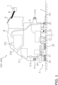
- FIG. 1 is a diagram illustrating an overall structure of an example of the autonomous traveling device.
- the autonomous traveling device 100 is a cleaning machine that autonomously reproduces set cleaning conditions and travel route.
- the autonomous traveling device 100 includes a traveling unit 1.
- the traveling unit 1 is a device that is configured to cause the autonomous traveling device 100 to travel.
- the traveling unit 1 includes a main body B that constitutes a main body of the autonomous traveling device 100.
- the traveling unit 1 includes, at each of left and right ends of a bottom of the main body B, a travel motor 11 and a main wheel 13 that is connected to an output rotation shaft of the travel motor 11 and is rotated along with rotation of the travel motor 11.
- the autonomous traveling device 100 includes a cleaning unit 3.
- the cleaning unit 3 is a device placed at the bottom of the main body B so as to clean a floor surface F according to designated cleaning conditions.
- the cleaning unit 3 of this embodiment includes a washing liquid discharge port 31, a squeegee 33, and a cleaning member 35.
- the washing liquid discharge port 31 discharges washing liquid (such as water) to the floor surface F in front of the main body B.
- the washing liquid is supplied from a washing liquid supply tank 311 by a washing liquid supply pump 313.
- the squeegee 33 is placed on the rear side of the bottom of the main body B so as to collect the washing liquid remaining on the floor surface F.
- the cleaning member 35 is placed on the front side of the bottom of the main body B and is rotated when a cleaning member rotation motor 351 rotates. The cleaning member 35 rotates on the floor surface F with the washing liquid so as to clean the floor surface F.
- the autonomous traveling device 100 can perform a cleaning operation for polishing the floor surface F using the washing liquid.
- the squeegee 33 may be provided with a suction opening 33a.
- the suction opening 33a sucks the washing liquid, dust, and the like, collected by the squeegee 33.
- the suction opening 33a is connected to a collecting member 333.
- a negative pressure can be generated in the collecting member 333 by a suction motor 331.
- the autonomous traveling device 100 includes a control unit 5 (an example of a route planning device).
- the control unit 5 is a computer system including a CPU, a storage device (such as a RAM, a ROM, a hard disk drive, or an SSD), and various interfaces.
- the control unit 5 performs various controls related to the autonomous traveling device 100 (described later).
- the autonomous traveling device 100 includes a travel route teaching unit 7.
- the travel route teaching unit 7 is a device that is configured to accept moving operations by an operator of the traveling unit 1.
- the travel route teaching unit 7 is attached to the upper rear side of the main body B via an attachment member 8. In this way, the operator can operate the travel route teaching unit 7 so as to perform the moving operation of the traveling unit 1 (described later).
- the travel route teaching unit 7 may not be attached to the main body B.
- the travel route teaching unit 7 is a controller such as a joy stick. In this way, the operator can remotely control the autonomous traveling device 100.
- the autonomous traveling device 100 includes a setting unit 9.
- the setting unit 9 is a console pane that is configured to make various settings related to the autonomous traveling device 100.
- the setting unit 9 is attached to an upper rear surface of the main body B.
- the setting unit 9 is placed near the travel route teaching unit 7. In this way, the operator can operate the setting unit 9 while operating the travel route teaching unit 7 so as to operate the traveling unit 1.
- the setting unit 9 may not be attached to the main body B.
- the setting unit 9 can be a console such as a portable terminal capable of wireless communication. In this way, the operator can remotely set the autonomous traveling device 100.
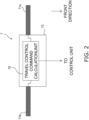
- FIG. 2 is a diagram illustrating an example of a structure of the travel route teaching unit.
- the travel route teaching unit 7 includes handles 71a and 71b.
- the handles 71a and 71b are fixed to the right and left sides of a case 73, respectively.
- the handles 71a and 71b are used when the operator operates the autonomous traveling device 100.
- the operator who grips the handles 71a and 71b can apply a force to the autonomous traveling device 100 to pull it to the operator or push it via the handles 71a and 71b.
- the operator can adjust traveling direction of the autonomous traveling device 100. For instance, when applying a force to the right side handle 71a viewed from the front of the autonomous traveling device 100 so as to pull the autonomous traveling device 100, the autonomous traveling device 100 turns left.
- the handles 71a and 71b are mounted to the case 73 in a rotatable manner.
- the handles 71a and 71b are connected to the control unit 5 via a travel control command calculation unit 75.
- the travel control command calculation unit 75 converts rotations of the handles 71a and 71b into electric signals and outputs them to the control unit 5. In this way, the operator can control the autonomous traveling device 100 (traveling unit 1) by rotation operations of the handles 71a and 71b.
- the operator may be able to switch between forward and backward movements of the autonomous traveling device 100 by adjusting rotation directions of the handles 71a and 71b.
- the operator may be able to adjust the driving speed of the autonomous traveling device 100.
- differentiating amounts of rotation of the handles 71a and 71b it may be possible to change driving direction of the autonomous traveling device 100.
- FIG. 3 is a diagram illustrating an example of a structure of the setting unit.
- the setting unit 9 includes a switching unit 91.
- the switching unit 91 selects an operation mode of the autonomous traveling device 100 and outputs the selected mode to the control unit 5.
- the operation modes of the autonomous traveling device 100 include an autonomous travel mode and a manual operation mode.
- the autonomous travel mode is an operation mode in which the autonomous traveling device 100 autonomously travels and cleans the floor surface F.
- the manual operation mode is an operation mode in which the autonomous traveling device 100 can be manually operated by the operator.
- the switching unit 91 can be constituted of a selector switch as illustrated in Fig. 3 , for example.
- the setting unit 9 includes a manual operation memory switch 92.
- the manual operation memory switch 92 is a switch for the operator to start or stop storing the manual operation of the autonomous traveling device 100.
- the operation mode for storing (teaching) cleaning conditions and travel route of the manual operation by the operator is referred to as a manual operation teaching mode.
- the manual operation teaching mode is started as a sub operation mode of the manual operation mode.
- the manual operation memory switch 92 may be a push button switch as illustrated in Fig. 3 , for example. In this case, switching of the manual operation memory switch 92 is made by pressing the push button switch.
- the setting unit 9 includes a setting operation unit 93.
- the setting operation unit 93 is constituted of a push switch or the like, for example.
- the setting operation unit 93 accepts various setting inputs related to the autonomous traveling device 100.
- a setting conversion unit 94 converts the input accepted by the setting operation unit 93 into a signal that the control unit 5 can decode.
- the setting conversion unit 94 is a signal conversion circuit or a computer system that can perform signal conversion.
- the setting unit 9 includes a display 95.
- the display 95 displays various setting information related to the autonomous traveling device 100, which are currently set.
- the display 95 is, for example, a liquid crystal display, an organic EL display, or other display.
- the display 95 may further display a current operation mode (the autonomous travel mode, the manual operation mode, or the manual operation teaching mode), operation hours, remaining battery capacity for driving the autonomous traveling device 100, and the like.
- the display 95 may be provided with a touch panel.
- the switching unit 91, the manual operation memory switch 92, and/or the setting operation unit 93 may be realized by the touch panel.
- the setting unit 9 may include a cleaning condition teaching unit 96.
- the cleaning condition teaching unit 96 accepts an input of cleaning conditions from the operator.
- a cleaning control command calculation unit 97 converts the cleaning conditions accepted by the cleaning condition teaching unit 96 into a signal that the control unit 5 can decode, and outputs the signal to the control unit 5.
- the cleaning control command calculation unit 97 is a signal conversion circuit or a computer system that can perform signal conversion.
- Fig. 4 is a diagram illustrating a functional block structure of the entire control unit.
- the whole or a part of the functional blocks of the control unit 5 described below may be realized by a program that a computer system constituting the control unit 5 can perform.
- the program may be stored in a memory unit and/or the storage device.
- the whole or a part of individual functional blocks of the control unit 5 may be realized as a custom IC such as a system on chip (SoC).
- SoC system on chip
- the control unit 5 may be constituted of a single computer system or a plurality of computer systems. If a plurality of computer systems constitute the control unit 5, for example, functions realized by the plurality of functional blocks of the control unit 5 can be assigned to the plurality of computer systems to execute at arbitrary ratios.
- the control unit 5 includes a cleaning control unit 51.
- the cleaning control unit 51 supplies power for controlling rotation speeds, outputs, or the like to the cleaning member rotation motor 351, the washing liquid supply pump 313, and the suction motor 331.
- the cleaning control unit 51 may input taught cleaning conditions from the cleaning condition teaching unit 96 via the cleaning control command calculation unit 97, and may control the cleaning member rotation motor 351, the washing liquid supply pump 313, and the suction motor 331, based on the taught cleaning condition.
- the cleaning control unit 51 may input reproducing cleaning conditions from a control management unit 55 when the autonomous travel mode is executed.
- the reproducing cleaning conditions are set values of cleaning conditions in the autonomous travel mode.
- the cleaning control unit 51 may control the cleaning unit 3 based on the reproducing cleaning conditions that are input.
- the control unit 5 includes a travel control unit 53.
- the travel control unit 53 controls the travel motor 11 based on a travel control command.
- the travel control command is a command based on amounts of rotation and rotation directions of the handles 71a and 71b input from the travel route teaching unit 7.
- the travel control command is a command input from the control management unit 55.
- the travel control unit 53 calculates rotation speed of the travel motor 11 based on a pulse signal output from an encoder 111 mounted to the output rotation shaft of the travel motor 11.
- the control unit 5 includes the control management unit 55.
- the control management unit 55 manages travel of the autonomous traveling device 100. Specifically, based on information obtained by a front detector 41a, a rear detector 41b, and/or the encoder 111, the control management unit 55 calculates position information indicating a position on the floor surface F at which the autonomous traveling device 100 is moving.
- the control management unit 55 creates a traveling schedule 500 using the above-mentioned position information when the manual operation teaching mode is executed.
- the control management unit 55 may calculate cleaning conditions in the autonomous travel mode and may associate them with the traveling schedule 500.
- the control management unit 55 calculates a reproducing travel control command based on data stored in the traveling schedule 500.
- the calculated reproducing travel control command is output to the travel control unit 53.
- the travel control unit 53 controls the travel motor 11 based on the reproducing travel control command, so that the autonomous traveling device 100 can autonomously move.
- the control management unit 55 may control the cleaning control unit 51 based on the cleaning conditions stored in the traveling schedule 500. In this way, while the autonomous traveling device 100 is autonomously traveling according to the traveling schedule 500, it can autonomously perform the cleaning operation according to the cleaning conditions.
- the control unit 5 includes a storage unit 57.
- the storage unit 57 is a part or the whole of the storage device of the computer system constituting the control unit 5.
- the storage unit 57 stores various information related to the autonomous traveling device 100. Specifically, the storage unit 57 stores the traveling schedule 500 created by the control management unit 55, and various settings related to the autonomous traveling device 100 input from the setting operation unit 93 or the setting conversion unit 94.
- the travel control unit 53 and the control management unit 55 can read out various settings related to the autonomous traveling device 100 and/or the traveling schedule 500 stored in the storage unit 57, as necessary, and can perform various adjustments and controls based on them.
- control unit 5 may include a data writing device (not shown) for storing information such as the traveling schedule 500 stored in the storage unit 57, in another storage medium.
- Fig. 5 is a diagram illustrating a detailed structure of functional blocks of the travel control unit.
- the travel control unit 53 includes a travel switching unit 531.
- the travel switching unit 531 has three terminals d, e, and f.
- the terminal d is connected to the travel route teaching unit 7
- the terminal e is connected to a motor control unit 533
- the terminal f is connected to the control management unit 55.
- the travel switching unit 531 selects a connection between the terminal e and the terminal d, or a connection between the terminal e and the terminal f, based on the operation mode selected by the switching unit 91.
- the travel switching unit 531 connects the terminal e and the terminal d. In this way, the travel switching unit 531 can connect the travel route teaching unit 7 to the motor control unit 533. In other words, when the manual operation mode or the manual operation teaching mode is executed, the travel switching unit 531 can send to the motor control unit 533 signals indicating amounts of rotation and/or rotation directions of the handles 71a and 71b.
- the travel switching unit 531 connects the terminal e and the terminal f. In this way, the travel switching unit 531 can connect the control management unit 55 to the motor control unit 533. In other words, when the autonomous travel mode is executed, the travel switching unit 531 can send to the motor control unit 533 the reproducing travel control command output from the control management unit 55.
- the motor control unit 533 calculates target rotation speed of the travel motor 11 based on the input amounts of rotation and rotation directions of the handles 71a and 71b, or the reproducing travel control command.
- the motor control unit 533 outputs to the travel motor 11 a drive power for rotating the travel motor 11 at the target rotation speed.
- the motor control unit 533 calculates an actual rotation speed of the travel motor 11 based on the pulse signal from the encoder 111, and calculates the drive power to be output to the travel motor 11. For instance, the motor control unit 533 uses a proportional integral (PI) control theory, a proportional integral differential (PID) control theory, or the like, so as to control the travel motor 11.
- PI proportional integral
- PID proportional integral differential
- the travel motor 11 and the main wheel 13 are placed at each of the left and right ends of the bottom of the main body B.
- the motor control unit 533 controls rotation speeds and rotation directions of the left and right travel motors 11 independently, so as to determine driving direction of the autonomous traveling device 100.
- FIG. 6 is a diagram illustrating a detailed structure of the functional block of the control management unit.
- the control management unit 55 includes an SLAM unit 551.
- the SLAM unit 551 creates a local map and a global map GM (an example of a first map) using information about obstacles in front of the autonomous traveling device 100 and information about obstacles in rear of the autonomous traveling device 100.
- the local map is map information indicating positions of obstacles around the autonomous traveling device 100, and is created by coordinate conversion, as necessary, of information about obstacles obtained by the front detector 41a and the rear detector 41b.
- the global map GM is map information indicating positions of obstacles existing in a movement environment EV, and is created by linking local maps obtained by moving the autonomous traveling device 100 in the movement environment EV, in this embodiment.
- the information about obstacles in front of the autonomous traveling device 100 is obtained by using the front detector 41a ( Fig. 1 ).
- the information about obstacles in the rear of the autonomous traveling device 100 is obtained by using the rear detector 41b ( Fig. 1 ).
- the front detector 41a and the rear detector 41b are laser range finders (LRFs) having a detection range of 180 degrees or more, for example.
- LRFs laser range finders
- the distance between the traveling unit 1 and the obstacle, and the direction to the obstacle can be obtained as the information about the obstacle.
- the information obtained by the front detector 41a and the rear detector 41b may be two-dimensional information indicating the position of the obstacle on a predetermined plane, or may be three-dimensional information further including the height position of the obstacle.
- the SLAM unit 551 estimates the own position of the autonomous traveling device 100 on predetermined coordinates, based on the local map, the global map GM, and amount of rotation of the travel motor 11. The amount of rotation of the travel motor 11 is obtained by the encoder 111. Specifically, the SLAM unit 551 performs the own position estimation as follows.
- the SLAM unit 551 performs position estimation by dead reckoning based on the amount of rotation of the travel motor 11 from the last own position estimation to the present.
- the SLAM unit 551 determines a plurality of own position candidates at the position estimated by dead reckoning and around it.
- the SLAM unit 551 puts a current local map at each of the plurality of own position candidates on the global map GM, and calculates a degree of matching between the current local map positioned at each own position candidate and the global map GM.
- the SLAM unit 551 estimates that the current own position is one of the own position candidates, which has the maximum degree of matching between the current local map and the global map GM.
- the control management unit 55 includes a route creation unit 553.
- the route creation unit 553 creates the traveling schedule 500, and stores it in the storage unit 57.
- the traveling schedule 500 indicates the route along which the autonomous traveling device 100 autonomously travels.
- the traveling schedule 500 indicates the route along which the autonomous traveling device 100 autonomously travels thoroughly (to fill in) a travel area TA set in the movement environment EV (global map GM).
- the control management unit 55 includes a travel reproducing unit 555.
- the travel reproducing unit 555 executes the autonomous travel mode, it calculates a control command (the reproducing travel control command) based on the information stored in the traveling schedule 500 and the estimated position information obtained from the SLAM unit 551. This control command enables the autonomous traveling device 100 to autonomously travel along the travel route indicated in the traveling schedule 500.
- the travel reproducing unit 555 outputs the calculated reproducing travel control command to the travel control unit 53.
- the travel reproducing unit 555 may output to the cleaning control unit 51 the cleaning conditions associated with the traveling schedule 500.
- the travel reproducing unit 555 is connected to an obstacle detection unit 43.
- the obstacle detection unit 43 detects obstacles existing in the driving direction of the autonomous traveling device 100.
- the obstacle detection unit 43 is an ultrasonic sensor placed on the front of the main body B, for example.
- the front detector 41a may be used as a sensor that detects obstacles in the driving direction.
- the travel reproducing unit 555 calculates the reproducing travel control command to avoid the obstacle, and outputs the reproducing travel control command to the travel control unit 53. In this way, even if the traveling schedule 500 is created without considering existence of obstacles, the autonomous traveling device 100 can autonomously travel while avoiding the detected obstacle.
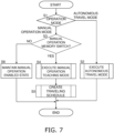
- Fig. 7 is a flowchart showing basic operations of the autonomous traveling device.
- the control unit 5 checks a status of the switching unit 91 (Step S1). If the switching unit 91 selects "automatic” (in the case of "autonomous travel mode” in Step S1), the autonomous travel mode is executed (Step S2). In other words, the autonomous traveling device 100 autonomously travels (performs cleaning operation) according to the traveling schedule 500 stored in the storage unit 57.
- Step S1 determines that the operation mode to be executed is the manual operation mode.
- Step S3 While executing the manual operation mode, if it is detected that the manual operation memory switch 92 is pressed ("Yes" in Step S3), the control unit 5 changes the operation mode to the manual operation teaching mode (Step S4). As a result, operations of the autonomous traveling device 100 by the operator after the manual operation memory switch 92 is pressed are stored.
- Step S4 while executing the manual operation teaching mode, the control unit 5 monitors whether or not the manual operation memory switch 92 is pressed. If the manual operation memory switch 92 is pressed while executing the manual operation teaching mode, the control unit 5 finishes the manual operation teaching mode at that timing. After that, in Step S5 the route creation unit 553 creates the traveling schedule 500 using the data taught in the manual operation teaching mode.
- Step S3 if the manual operation memory switch 92 is not pressed after changing to the manual operation mode ("No" in Step S3), the control unit 5 maintains the manual operation mode in which the operations by the operator are not stored, in Step S6.
- the autonomous traveling device 100 can execute the autonomous travel mode, the manual operation mode, or the manual operation teaching mode, according to the selection of the operation mode with the switching unit 91, and whether or not the manual operation memory switch 92 is pressed.
- FIG. 8 is a flowchart showing operations in the manual operation teaching mode.
- the global map GM indicating the movement environment EV is created, and an outer periphery BO' of the travel area TA where the autonomous traveling device 100 autonomously travels, is taught.
- Step S41 the operator of the autonomous traveling device 100 first causes the autonomous traveling device 100 to travel along the outer periphery BO' of the travel area TA set in the movement environment EV
- the SLAM unit 551 estimates points passed during the movement along the outer periphery BO' of the travel area TA, in Step S42.
- the SLAM unit 551 creates the local map every predetermined period (e.g. every control period of the control unit 5).
- the SLAM unit 551 estimates the current own position of the autonomous traveling device 100 using the local map described above and the global map GM that was created before the present execution of Step S42 and is stored in the storage unit 57.
- Step S43 the SLAM unit 551 combines the local map that was created when the present own position was estimated, with the global map GM that is currently stored in the storage unit 57, so that a new global map GM is created and stored in the storage unit 57.
- the SLAM unit 551 puts the local map created in Step S42 at a position corresponding to the current own position of the global map GM that has been created, so as to create the new global map GM.
- Step S44 the route creation unit 553 creates an outer peripheral boundary BO indicating the outer periphery of the travel area TA, as a set of the points passed by the autonomous traveling device 100 until the present own position is estimated.
- the route creation unit 553 obtains the current own position estimated in Step S42 from the SLAM unit 551, and combines coordinate values of this own position with the coordinate values of the own positions estimated before, so as to create the outer peripheral boundary BO as a set of the coordinate values of the own positions.
- Steps S41 to S44 described above are executed repeatedly until the manual operation teaching mode is finished (until "Yes” in Step S45), by an event such as when the manual operation memory switch 92 is pressed.
- Fig. 9 is a diagram illustrating an example of the movement environment.
- the travel area TA having the outer periphery BO' shown by a broken line is set in an area surrounded by a wall W (an area in which the autonomous traveling device 100 can travel).
- a large obstacle OB 1 that never moves and a small obstacle OB2 that moves exist in the travel area TA.
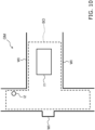
- the global map GM and the outer peripheral boundary BO as illustrated in Fig. 10 are created by executing Steps S41 to S45 described above while causing the autonomous traveling device 100 to travel along the outer periphery BO'.
- the global map GM is shown by solid lines
- the outer peripheral boundary BO is shown by a broken line.
- Fig. 10 is a diagram illustrating an example of the global map and the outer peripheral boundary.
- the global map GM includes obstacle information WI indicating the wall W of the movement environment EV, obstacle information I1 of the obstacle OB1 that never moves, and obstacle information I2 of the obstacle OB2 that moves.
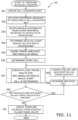
- Fig. 11 is a flowchart showing the operation of creating the traveling schedule.
- an operation of creating the traveling schedule 500 which is a filling travel route to fill in the travel area TA defined by the outer peripheral boundary BO, which has been created by executing Steps S41 to S45 described above, is described.
- Step S51 the route creation unit 553 creates a cell-converted map CM that expresses the global map GM as an aggregation of cells of the "cells C", using the global map GM created by executing Steps S41 to S45 described above.
- the cell C corresponds to a small region having a predetermined area in the movement environment EV Considering a process performed by the control unit 5, the cell C can be defined as a "structure" including, for example, parameters related to the cell C (e.g. a parameter for identifying the cell C, position information of the cell C, valid or invalid of the cell C, a score assigned to the cell C, and the like).
- parameters related to the cell C e.g. a parameter for identifying the cell C, position information of the cell C, valid or invalid of the cell C, a score assigned to the cell C, and the like.
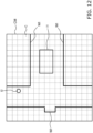
- the route creation unit 553 first puts the cells C on a coordinate plane defining the global map GM. After that, the route creation unit 553 projects the global map GM on the coordinate plane on which the cell C are placed, so as to create the cell-converted map CM. In this way, for example, the cell-converted map CM as illustrated in Fig. 12 is created corresponding to the global map GM illustrated in Fig. 10 .
- Fig. 12 is a diagram illustrating an example of the cell-converted map.
- the cell-converted map CM illustrated in Fig. 12 includes the obstacle information WI indicating the wall W, the obstacle information I1 of the obstacle OB1, and the obstacle information I2 of the obstacle OB2, which were included in the global map GM, as they are.
- the cell-converted map CM is map information associated with the global map GM, while it is created independently from the global map GM.
- the control unit 5 regards the cell-converted map CM as data different from the global map GM.
- the global map GM is used to estimate the own position of the autonomous traveling device 100 when the autonomous travel is performed.
- the cell-converted map CM is used to create a route creation map SM (described later) that is used to create the traveling schedule 500.
- Step S52 the route creation unit 553 sets the outer peripheral boundary BO by associating the outer peripheral boundary BO with the global map GM. Specifically, the outer peripheral boundary BO of the travel area TA is set in the cell-converted map CM that is associated with the global map GM.
- the route creation unit 553 makes the cell-converted map CM to include the outer peripheral boundary BO as a set of coordinate values of the own positions created by executing Steps S41 to S45 described above.
- Fig. 13 is a diagram illustrating an example of the cell-converted map after setting the outer peripheral boundary.
- the route creation unit 553 After setting the outer peripheral boundary BO in the cell-converted map CM, the route creation unit 553 deletes obstacle information included inside the outer peripheral boundary BO set in the cell-converted map CM, so as to create the route creation map SM (an example of a second map) in Step S53.
- the route creation unit 553 scans coordinate points (pixels in a two-dimensional cell-converted map CM or voxels in a three-dimensional cell-converted map CM) in the area surrounded by the outer peripheral boundary BO. If obstacle information exists in the coordinate point (pixel or voxel) in the area surrounded by the outer peripheral boundary BO, the route creation unit 553 deletes the obstacle information. In this way, the route creation unit 553 can delete the obstacle information inside the outer peripheral boundary BO by pixel or voxel.
- the route creation unit 553 can easily create the route creation map SM, in which all obstacle information I1 and I2 existing inside the outer peripheral boundary BO are deleted from the cell-converted map CM illustrated in Fig. 13 , without determining characteristics of the obstacles expressed by the obstacle information inside the outer peripheral boundary BO (such as whether or not to move).
- Fig. 14 is a diagram illustrating an example of the route creation map.
- Step S54 the route creation unit 553 determines valid cells VC and invalid cells INC for the cells C included in the route creation map SM.
- the valid cell VC is a cell in which the autonomous traveling device 100 can travel in the route creation map SM.
- the invalid cell INC is a cell in which the autonomous traveling device 100 cannot travel in the route creation map SM.
- the route creation unit 553 determines that the cells C including the obstacle information WI indicating the wall W or the outer peripheral boundary BO, and the cells C outside the obstacle information WI indicating the wall W or the outer peripheral boundary BO are the invalid cells INC.
- the route creation unit 553 assigns the invalid cells INC with a "score" indicating that the autonomous traveling device 100 cannot travel (e.g. 0 or a negative value such as -1).
- the route creation unit 553 determines that rest of the cells that are not the invalid cells INC among the cells C included in the route creation map SM are the valid cells VC.
- the travel area TA can be set in the route creation map SM. Specifically, the region occupied by the valid cells VC in the route creation map SM is set as the travel area TA.
- Step S54 in the route creation map SM illustrated in Fig. 14 , the valid cells VC and the invalid cells INC are determined as illustrated in Fig. 15 .
- white cells C are valid cells VC
- colored cells C are invalid cells INC.
- Fig. 15 is a diagram illustrating an example of valid cells and invalid cells in the route creation map.
- the route creation unit 553 After setting the travel area TA in the route creation map SM, the route creation unit 553 creates the traveling schedule 500, which is the filling travel route to fill in the travel area TA included in the route creation map SM created in Steps S51 to S54 described above.
- the filling travel route is created as follows.
- the route creation unit 553 divides the travel area TA into rectangular areas RA.
- the route creation unit 553 searches for a direction in which the rectangular area RA extends in the travel area TA.
- the direction in which the rectangular area RA extends is referred to as a "major direction”.
- the major direction of the rectangular area RA can be searched for as follows.
- the route creation unit 553 sets a predetermined reference axis in the route creation map SM, and rotates the route creation map SM by a predetermined angle.
- the route creation unit 553 defines a plurality of line segments that are parallel to the reference axis described above and connects boundaries (outer peripheral boundary BO) of the travel area TA in the entire travel area TA included in the route creation map SM after the rotation.
- the line segments, each of which connects two points on the outer peripheral boundary BO expressed as a row of points and are parallel to the reference axis are defined in the entire travel area TA.
- the route creation unit 553 integrates lengths of the line segments having a length in a predetermined range among the plurality of line segments. This calculation of the integrated value is performed on the line segments in a range sandwiched by boundary parts of the rectangular area.
- the boundary part of the rectangular area can be recognized as a part where the length of the line segment connecting boundaries of the travel area TA changes rapidly.
- the "length in a predetermined range” described above is, for example, a maximum length L max (e.g. a diagonal length of the rectangular area) of the rectangular area, and more than or equal to a length ( ⁇ ⁇ L max ) shorter than the maximum length L max of the rectangular area by a predetermined ratio ⁇ (0 ⁇ ⁇ ⁇ 1).
- the route creation unit 553 can determine the major direction of the rectangular area RA based on a rotation angle of the route creation map SM when a maximum integrated value is calculated, among the integrated values calculated for individual rotation angles in the travel area TA. Specifically, this rotation angle with opposite sign (- ⁇ if the rotation angle of the route creation map is ⁇ ) can be determined to be the major direction of the rectangular area RA.
- the route creation unit 553 can divide the travel area TA in the route creation map SM illustrated in Fig. 15 into three rectangular areas RA1 to RA3 as illustrated in Fig. 16 .
- arrows in the rectangular areas RA1 to RA3 indicate major directions of the rectangular areas RA1 to RA3, respectively.
- Fig. 16 is a diagram illustrating an example of a state where the travel area is divided into rectangular areas.
- the route creation unit 553 After dividing the travel area TA into the rectangular areas RA1 to RA3, the route creation unit 553 creates the filling travel routes for the rectangular areas RA1 to RA3 so as to fill in the rectangular areas RA1 to RA3, respectively. Specifically, the filling travel routes are created as follows.
- the route creation unit 553 determines a valid cell VC to be a start point of the filling travel route (referred to as a start cell SC) in each of the rectangular areas RA1 to RA3. For instance, the route creation unit 553 determines the start cell SC, which is a valid cell VC corresponding to the position where the autonomous traveling device 100 started traveling when teaching the outer periphery BO' of the travel area TA (when creating the outer peripheral boundary BO) or a position near the position, and exists in one of corners of the rectangular area.
- a start cell SC which is a valid cell VC corresponding to the position where the autonomous traveling device 100 started traveling when teaching the outer periphery BO' of the travel area TA (when creating the outer peripheral boundary BO) or a position near the position, and exists in one of corners of the rectangular area.
- the start cell SC as illustrated in Fig. 17 can be set for the route creation map SM illustrated in Fig. 16 .
- the start cell SC is set in a corner of the rectangular area RA1.
- the rectangular area in which the filling travel route is created first is determined as the rectangular area RA1.
- Fig. 17 is a diagram illustrating an example of the start cell determined in the rectangular area for which the filling travel route is created first.
- the route creation unit 553 creates the filling travel route in Step S57.
- the filling travel route created in this embodiment is a travel route that starts from the start cell SC and passes through all the valid cells VC included in the target rectangular area RA1 to RA3 (the rectangular area RA1 in the example of Fig. 17 ).
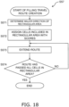
- the route creation unit 553 creates the filling travel route according to the process illustrated in a flowchart of Fig. 18.
- Fig. 18 is a flowchart showing a method of creating the filling travel route.
- a method of creating the filling travel route for the rectangular area RA1 is exemplified.
- the filling travel route for other rectangular areas RA2 and RA3 can also be created by the method performed for the rectangular area RA1.
- the route creation unit 553 determines the major direction of the rectangular area RA1.
- the major direction of the rectangular area RA1 can be the major direction that was determined when the travel area TA was divided into the rectangular areas RA1 to RA3 in Step S55 described above.
- Step S572 the route creation unit 553 assigns the valid cells VC in the rectangular area RA1 with scores. Specifically, the route creation unit 553 assigns higher scores to the valid cells VC apart from the start cell SC in the direction perpendicular to the major direction. On the other hand, the same score is assigned to the valid cells VC arranged in the major direction.
- Fig. 19 is a diagram illustrating an example of scores assigned to cells in the rectangular area.
- the valid cells VC arranged in the major direction from the start cell SC are assigned with a score of 11. This means that there are 11 valid cells in the major direction in the rectangular area RA1.
- the score increases by a multiple of 11 as they move away from the start cell SC in the direction perpendicular to the major direction.
- a score of 22 is assigned to the valid cell VC adjacent to the start cell SC in the direction perpendicular to the major direction.
- the same score of 22 is assigned to the valid cells VC arranged in the major direction from the valid cell VC assigned with a score of 22 as described above.
- the valid cells VC apart from the start cell SC more than the valid cell VC assigned with a score of 22, are assigned with scores of 33, 44, and 55, which are increased more as being apart from the start cell SC, and the valid cells VC arranged in the major direction are assigned with the same score.
- the route creation unit 553 extends the route from the start cell SC to the valid cells VC. Specifically, the route creation unit 553 extends the route from the start cell SC to the valid cell VC assigned with the maximum score out of the valid cells VC adjacent to the start cell SC in the major direction or the direction perpendicular to the major direction.
- the route creation unit 553 does not extend the route again to the valid cell VC to which the route is once extended, unless there is a special reason such that the route planning cannot be completed without passing the valid cell VC again.
- Step S573 described above is executed repeatedly as long as there is any valid cell VC where the route does not pass in the rectangular area RA1 (as long as "No" in Step S574).
- Fig. 20 is a diagram illustrating an example of the filling travel route.
- the filling travel route is created as a combination of first paths extending in the major direction in the rectangular area RA1 and second paths extending perpendicularly to the major direction.
- the filling travel route that thoroughly fills in the rectangular area RA1 can be created as a route along which the autonomous traveling device 100 can travel by simple movements of going straight and turning.
- the first path extends over a plurality of valid cells in the major direction.
- the second path extends only one cell except for the path starting from the start cell SC.
- the filling travel route created by executing Steps S571 to S574 described above includes longer paths in the major direction in the rectangular area. In this way, by setting longer paths along the major direction in the rectangular area, the number of turning of the autonomous traveling device 100 in the filling travel route can be reduced.
- Step S58 the route creation unit 553 determines whether or not there is any rectangular area RA1 to RA3 for which the filling travel route is not yet created.
- Step S58 If there is no rectangular area RA1 to RA3 for which the filling travel route is not created ("No" in Step S58), the process of creating the traveling schedule 500 proceeds to Step S61 described later.
- Step S59 the route creation unit 553 determines a new start cell SC of the filling travel route to be created next.
- the route creation unit 553 determines the new start cell SC, which is the valid cell VC having the shortest distance from an end cell EC that is the end point of the filling travel route created in the rectangular area RA1.
- the rectangular area RA2, RA3 including the new start cell SC can be determined as the rectangular area for which the filling travel route is to be created next.
- Fig. 21 is a diagram schematically illustrating an example of a method for determining the new start cell and the rectangular area for which the filling travel route is to be created next.
- the valid cell VC that can be connected to the end cell EC as the end point of the created filling travel route by the shortest distance is determined as the new start cell SC, and the rectangular area including the new start cell SC is determined as the rectangular area for which the filling travel route is to be created next, so that the traveling schedule 500 having the shortest distance and good travel efficiency can be created.
- Step S60 the route creation unit 553 connects the end cell EC as the end point of the created filling travel route and the determined new start cell SC via a connection path.
- Step S57 the filling travel route is created in the rectangular area including the new start cell SC.
- Steps S57 (Steps S571 to S574) to S60 described above are executed repeatedly until the filling travel route is created in all rectangular area RA1 to RA3 (i.e., until "No" in Step S58).
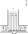
- the filling travel route is created, which thoroughly fill in the travel area TA as illustrated in Fig. 22 , for the entire travel area TA illustrated in Fig. 9 and the like.
- the travel area TA is shown by a broken line, and the filling travel route created for the entire travel area TA is shown by thick arrows.
- Fig. 22 is a diagram illustrating an example of the filling travel route created for the entire travel area.
- Step S61 the route creation unit 553 converts the created filling travel route into a set of points through which the autonomous traveling device 100 passes.
- the route creation unit 553 assigns the points created by the conversion of the filling travel route with times at which the points are passed, respectively.
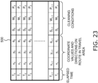
- the route creation unit 553 assigns the cleaning conditions at each point to the corresponding point, so as to create the traveling schedule 500 as illustrated in Fig. 23.
- Fig. 23 is a diagram illustrating an example of the traveling schedule.
- symbols T 0 , T 1 , ... T n represent times at which the point on the filling travel route are passed, respectively.
- (x 0 , y 0 ), (xi, yi), ... (x n , y n ) express coordinate values of the points on the filling travel route.
- ⁇ 0 , ⁇ 1 , ... ⁇ n respectively represent directions of the autonomous traveling device 100 at the points on the filling travel route.
- symbols S 0 , S 1 , ... S n respectively represent supply amounts of the washing liquid at the points on the filling travel route.
- W 0 , W 1 , ... W n respectively represent cleaning powers on the floor surface F at the points on the filling travel route.
- P 0 , P 1 , ... P n respectively represent sucking forces of the suction opening O2 at the points on the filling travel route.
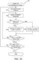
- Fig. 24 is a flowchart showing an operation of the autonomous traveling device when the autonomous travel mode is executed.
- the autonomous traveling device 100 autonomously travels by reproducing the travel route recorded in the traveling schedule 500.
- the user moves the autonomous traveling device 100 to a start position of the autonomous travel.
- the start position of the autonomous travel is the point associated with elapsed time T 0 in the traveling schedule 500.
- Step S21 the travel reproducing unit 555 determines a target position to which the autonomous traveling device 100 autonomously travels.
- the travel reproducing unit 555 determines the current elapsed time associated with the point closest to the current position on the traveling schedule 500, and the point associated with next elapsed time after the current elapsed time is determined as a next target position. In this way, the next target position is set on the filling travel route recorded in the traveling schedule 500.
- the travel reproducing unit 555 After determining the target position, the travel reproducing unit 555 starts the control for the autonomous travel. First, in Step S22, the travel reproducing unit 555 grasps the current position of the autonomous traveling device 100.
- the SLAM unit 551 estimates the current own position of the autonomous traveling device 100, by the process described above, based on the amount of rotation of the travel motor 11 measured by the encoder 111 after the previous own position estimation until the present own position estimation, the local map created based on the obstacle information obtained at the current position, and the global map GM stored in the storage unit 57. After that, the travel reproducing unit 555 inputs the own position estimated by the SLAM unit 551.
- Step S23 the travel reproducing unit 555 determines whether or not the obstacle detection unit 43 has detected an obstacle in the interference region on the future travel route that is the travel route from the current position to the target position.
- the interference region means a region where the autonomous traveling device 100 passes when the autonomous traveling device 100 travels along the future travel route.
- the interference region is determined based on a size of the main body B of the autonomous traveling device 100, the driving speed of the autonomous traveling device 100, and the like.
- the obstacle included in the interference region can collide with the autonomous traveling device 100 that is traveling along the future travel route.
- Step S24 the travel reproducing unit 555 calculates the reproducing travel control command to cause the autonomous traveling device 100 to travel along the future travel route described above. Specifically, the travel reproducing unit 555 calculates the reproducing travel control command to cause the autonomous traveling device 100 to travel from the current position to the target position determined in Step S21. The travel reproducing unit 555 outputs the calculated reproducing travel control command to the travel control unit 53.
- Step S25 the travel reproducing unit 555 plans a route to avoid the detected obstacle (referred to as an avoidance route), and calculates the reproducing travel control command to cause the autonomous traveling device 100 to travel the planned route.
- the travel reproducing unit 555 outputs the calculated reproducing travel control command to the travel control unit 53.
- Step S25 the travel reproducing unit 555 changes the target position determined in Step S21 described above, depending on the planned avoidance route. For instance, among the points stored in the traveling schedule 500, the point apart from the current position by a predetermined distance is set as the new target position.
- the travel control unit 53 which has received the reproducing travel control command described above, controls the travel motor 11 based on the received reproducing travel control command, so as to cause the autonomous traveling device 100 to travel according to the reproducing travel control command.
- the travel reproducing unit 555 calculates the reproducing cleaning conditions based on the cleaning conditions associated with the current elapsed time, and outputs the reproducing cleaning conditions to the cleaning control unit 51. In this way, it can control the cleaning unit 3 according to the calculated reproducing cleaning conditions.
- the travel reproducing unit 555 determines whether or not the autonomous traveling device 100 has reached the determined target position, in Step S26. For instance, if the current position is identical to the target position or within a predetermined range therefrom, it can be determined that the autonomous traveling device 100 has reached the target position.
- Step S22 If the autonomous traveling device 100 has not yet reached the target position ("No" in Step S26), the autonomous travel operation returns to Step S22.
- Steps S22 to S25 described above are executed repeatedly until the autonomous traveling device 100 reaches the target position. It should be noted that Steps S22 to S25 described above are executed every control period of the control unit 5.
- Step S27 the travel reproducing unit 555 determines whether or not the travel operation stored in the traveling schedule 500 is all performed.
- the determination whether or not the travel operation stored in the traveling schedule 500 is all performed can be made, for example, by detecting an identifier at the end of the traveling schedule 500 (such as an identifier indicating an "end of file").
- Step S27 the autonomous travel operation returns to Step S21.
- Steps S21 to S26 described above are executed repeatedly until the travel operation stored in the traveling schedule 500 is all performed.
- Step S27 execution of the autonomous travel mode is finished.
- Fig. 25 is a diagram schematically illustrating a specific example of the autonomous travel.
- Steps S21 to S27 described above is performed so as to cause the autonomous traveling device 100 to autonomously travel, using the traveling schedule 500 indicating the filling travel route to fill in the travel area TA set in the movement environment EV illustrated in Fig. 9 .
- the filling travel route generated by executing Steps S51 to S60 described above (the route shown by broken lines in Fig. 25 ) is partially overlapped with the obstacles OB1 and OB2.
- the reason why, is that the filling travel route is created using the route creation map SM from which obstacle information I1 and I2 indicating the obstacles OB1 and OB2 are deleted. In other words, the filling travel route is created without considering existence of the obstacles OB1 and OB2.
- the autonomous traveling device 100 While performing the autonomous travel mode according to Steps S21 to S27 described above, the autonomous traveling device 100 monitors whether or not an obstacle exists in the movement environment EV If there is an obstacle on the created filling travel route, the autonomous traveling device 100 autonomously travels so as to avoid the obstacle. In this way, even if the created filling travel route overlaps with the obstacle OB1, OB2, as illustrated in Fig. 25 , the autonomous traveling device 100 can autonomously travel according to the created filling travel route while avoiding the obstacle existing when the autonomous travel mode is executed.
- the autonomous traveling device 100 travels the route to avoid the obstacle OB 1, which exists when the manual operation teaching mode or the autonomous travel mode is executed.
- the autonomous traveling device 100 does not travel the route to avoid the obstacle OB2 but travels according to the created filling travel route.
- the autonomous traveling device 100 can create the filling travel route to appropriately fill in the travel area TA, even if the obstacle OB2 existing in the travel area TA when the global map GM is created will not exist when the autonomous travel is performed.
- the autonomous traveling device 100 can detect the obstacle when the autonomous travel is performed, so that it can autonomously travel the route to avoid the obstacle.
- An autonomous traveling device 200 according to the second embodiment is different from the first embodiment only in that the route creation unit 553 selectively deletes the obstacle information existing inside the outer peripheral boundary BO, when the route creation map SM is created, and structural elements and functions of the autonomous traveling device 200 according to the second embodiment are the same as those of the autonomous traveling device 100 according to the first embodiment. Therefore, description of other structural elements and functions are omitted here.
- the route creation unit 553 deletes obstacle information matching a predetermined condition among obstacle information existing inside the outer peripheral boundary BO, in Step S53 in the flowchart of Fig. 11 (the step of creating the route creation map SM).
- This "predetermined condition” is a condition that the obstacle may move out of the travel area TA in a short time.
- the obstacle information that matches the "predetermined condition" described above for example, there is obstacle information that indicates an obstacle having a predetermined size or smaller among the obstacle information existing inside the outer peripheral boundary BO.
- the determination whether or not the obstacle information existing inside the outer peripheral boundary BO is the obstacle information indicating an obstacle having a predetermined size or smaller is made, for example, by a method of recognizing the size of the obstacle by image processing of the obstacle information, a method of calculating the area of the range surrounded by the obstacle information, or the like.
- the obstacle information matching the "predetermined condition” for example, there is the obstacle information indicating a dynamic obstacle among the obstacle information existing inside the outer peripheral boundary BO.
- the appropriate route creation map SM can be created.
- the determination whether or not the obstacle information existing inside the outer peripheral boundary BO is the obstacle information indicating a dynamic obstacle is made, for example, based on whether or not the target obstacle information moves every predetermined time, and/or whether or not the target obstacle information is moving continuously for a predetermined time or longer.
- the determination whether or not the obstacle information is moving is made, for example, by a method of recognizing the shape by image processing of the obstacle information and determining whether or not the shape is unnaturally distorted, or by a method of determining whether or not a plurality of obstacle information exist continuously for the same obstacle, or the like.
- the cells C within the area surrounded by the obstacle information are determined to be the invalid cells INC in Step S54 described above.
- the filling travel route to avoid the obstacle information remained without being deleted can be created by executing Steps S51 to S60 described above.
- the outer peripheral boundary BO is created by:
- the outer peripheral boundary BO is created by causing the autonomous traveling device 100 to actually travel along the outer periphery BO' of the travel area TA.
- a boundary line corresponding to the outer peripheral boundary BO is drawn on the global map GM, using image editing software such as CAD software, software dedicated to drawing the outer peripheral boundary BO, or the like, and hence the outer peripheral boundary BO is created.
- the third embodiment is different from the first embodiment or the second embodiment only in that the outer peripheral boundary BO can be created without executing the manual operation teaching mode, and structural elements and functions of the autonomous traveling device 200 according to the third embodiment are the same as those of the autonomous traveling device 100 according to the first embodiment. Therefore, description of other structural elements and functions are omitted here.
- the global map GM may be created by executing the manual operation teaching mode similarly to the first embodiment, or may be created using image editing software such as CAD software, software dedicated to drawing the outer peripheral boundary BO, or the like.
- the outer periphery BO' of the travel area TA is taught by causing the autonomous traveling device 100 to travel in the movement environment EV, while the filling travel route to fill in the travel area TA is created by information processing by the route creation unit 553.
- the filling travel route is not one that is taught by causing the autonomous traveling device 100 to actually travel along the filling travel route.
- the SLAM unit 551 may not be able to perform the own position estimation accurately during the autonomous travel of the autonomous traveling device 100 along the filling travel route.
- the filling travel route is created in a region where there is no obstacle that can be detected by the front detector 41a or the rear detector 41b, or in a region where an obstacle is detected but has a simple shape, a result of the map matching between the global map GM and the local map is inaccurate when the autonomous traveling device 100 is in the region. As a result, in the region, the SLAM unit 551 cannot accurately perform the own position estimation.
- an autonomous traveling device 400 after the filling travel route is created, the autonomous traveling device 400 "virtually" travels along the filling travel route, and it is determined whether or not the own position estimation can be accurately performed in the filling travel route.
- the autonomous traveling device 400 according to the fourth embodiment is different from the autonomous traveling device 100 according to the first embodiment, only in that the autonomous traveling device 400 virtually travels along the filling travel route after the filling travel route is created, and that it is determined whether or not the own position estimation can be accurately performed in the filling travel route, and other structural elements and functions are the same as those of the autonomous traveling device 100 according to the first embodiment. Therefore, description of other structural elements and functions are omitted here.
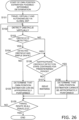
- Fig. 26 is a flowchart showing an operation of determining whether or not the own position estimation can be performed.
- the determination operation illustrated in Fig. 26 is performed by the SLAM unit 551.
- Step S101 the SLAM unit 551 causes the autonomous traveling device 400 to virtually and autonomously travels along the filling travel route in the global map GM.
- Step S102 the SLAM unit 551 attempts to virtually detect an obstacle (obstacle information) in the global map GM at the current position in the global map GM. Specifically, it attempts to detect the obstacle information as follows.
- the SLAM unit 551 virtually outputs a beam L for detecting an obstacle from the front detector 41a and the rear detector 41b radially within the detection ranges of the detectors.
- the SLAM unit 551 detects obstacle information intersecting the beam L. In this case, it is supposed that the beam intersects only one obstacle information.
- obstacle information I31 of the obstacle OB3 and two obstacle information I41 and I42 of the obstacle OB4 are virtually detected. It should be noted that the obstacle OB5 is hidden behind the obstacle OB3 when viewing from the autonomous traveling device 400, and hence obstacle information of the obstacle OB5 is not detected.
- Fig. 27 is a diagram illustrating an example of a detection state of obstacle information in the global map.
- the SLAM unit 551 simulates whether or not the autonomous traveling device 400 can perform the own position estimation while traveling along the filling travel route, based on the virtual obstacle detection status.
- the SLAM unit 551 determines whether or not the autonomous traveling device 100 can detect the obstacle at the current position in Step S103. As an example, the SLAM unit 551 calculates the sum of lengths of the detected obstacle information, and determines that the obstacle can be detected if the sum of lengths of the obstacle information is a predetermined value or more.
- the sum of lengths of the detected obstacle information corresponds to amount of the obstacle information that can be used for the map matching.
- Accuracy of the own position estimation by the map matching depends on the amount of the obstacle information (the local map) that can be used for the map matching. Therefore, the fact that the sum of lengths of the detected obstacle information is a predetermined value or more means that sufficient amount of the obstacle information (the local map) can be detected so that the own position estimation can be accurately performed by the map matching.
- Step S104 the SLAM unit 551 further determines whether or not the shape formed by the obstacle information (i.e. the shape of the local map) is a simple shape.
- the determination whether or not the shape formed by the detected obstacle information is a simple shape is made, for example, based on a ratio of linear obstacle information facing the same direction, or the like.
- the shape formed by the detected obstacle information is a simple shape such as two parallel straight lines positioned with a predetermined space therebetween, it may be difficult to determine the local map (position and direction thereof) mostly matched with the global map GM uniquely, and hence accuracy of the own position estimation is deteriorated.
- the case where the shape formed by the detected obstacle information is a simple shape is, for example, a case where the autonomous traveling device 100 exists in a linear passage sandwiched between two walls.
- Step S105 the SLAM unit 551 determines that the own position estimation can be appropriately performed in the filling travel route (at the current position thereof).
- the SLAM unit 551 determines that the state of the current obstacle detection is inappropriate.
- Step S106 the SLAM unit 551 determines whether or not the inappropriate state of the obstacle detection has continued for a predetermined period of time or longer.
- the inappropriate state of the obstacle detection does not dissolve after the autonomous traveling device 100 virtually travels a predetermined distance, it is determined that the inappropriate state of the obstacle detection has continued for a predetermined period of time or longer.
- Step S107 the SLAM unit 551 issues warning that the own position estimation may not be appropriately performed. For instance, the SLAM unit 551 issues warning by generating a warning sound, displaying a warning message on a display screen of the setting unit 9, or other method.
- Step S108 the SLAM unit 551 notifies the user that the outer peripheral boundary BO is not appropriate, because the own position estimation cannot be appropriately performed in a filling route to fill in the outer peripheral boundary BO taught this time. For instance, the SLAM unit 551 performs the notification described above by generating a warning sound, displaying on the display screen of the setting unit 9 that the outer peripheral boundary BO taught this time is not appropriate, or other method.
- the SLAM unit 551 may stop the own position estimation by the map matching at the point included in the route area described above of the traveling schedule 500, and may add a symbol, or the like to command to perform the own position estimation based on only the amount of rotation of the travel motor 11.
- the SLAM unit 551 can perform the own position estimation based on only the amount of rotation of the travel motor 11 at the point assigned with the symbol, or the like.
- the SLAM unit 551 executes Steps S101 to S108 described above until virtually traveling all the filling travel route indicated in the traveling schedule 500 (as long as "No" in Step S109).
- Steps S101 to S109 described above when the autonomous traveling device 100 autonomously travels along the filling travel route, it can predict, before performing the autonomous travel, whether or not the own position estimation can be performed using the global map GM and the obstacle information (the local map) when performing the autonomous travel.
- Steps S102 to S103 described above by determining that the own position estimation of the autonomous traveling device 400 cannot be performed, it is possible to predict, before the autonomous travel is performed, that an obstacle will not be detected when autonomously traveling along the filling travel route, and that the own position estimation will be unable to be performed using the global map GM and the obstacle information (the local map) when performing the autonomous travel.
- Steps S102 and S103 described above has a simple shape
- the own position estimation of the autonomous traveling device 400 it is possible to predict, before the autonomous travel is performed, that only a simple shape obstacle will be detected when autonomously traveling along the filling travel route, and that the own position estimation will be unable to be performed using the global map GM and the obstacle information (the local map) when performing the autonomous travel, or accuracy of the own position estimation may be deteriorated.
- the present invention can be widely applied to autonomous traveling devices that can autonomously travel to fill in a travel area set in a movement environment, and travels while avoiding obstacles existing in the travel area.
Landscapes
- Engineering & Computer Science (AREA)
- Radar, Positioning & Navigation (AREA)
- Remote Sensing (AREA)
- Physics & Mathematics (AREA)
- Automation & Control Theory (AREA)
- General Physics & Mathematics (AREA)
- Aviation & Aerospace Engineering (AREA)
- Optics & Photonics (AREA)
- Electromagnetism (AREA)
- Control Of Position, Course, Altitude, Or Attitude Of Moving Bodies (AREA)
Abstract
Description
- The present invention relates to an autonomous travel route planning method for an autonomous traveling body. In particular, the present invention relates to a method for planning an autonomous travel route for an autonomous traveling body, which is configured to autonomously travel to fill in a travel area set in a movement environment and to travel while avoiding obstacles existing in the travel area, a method for causing the autonomous traveling body to autonomously travel the planned autonomous travel route, and a program that causes a computer to execute these methods.
- Conventionally, there is known an autonomous traveling body that can autonomously travel a travel route (referred to as a filling travel route) to fill in a travel area set in a movement environment (see, for example, Patent Citation 1).
- The filling travel route is created by setting a travel area on an environmental map indicating the movement environment, and by planning a travel route in which straight paths and turning paths are combined in the travel area.
- Patent Citation 1:
PCT Publication No. 2018/043180 - In the movement environment, there may be an obstacle that the autonomous traveling body has to avoid. Further, the environmental map is used for the autonomous traveling body to perform an own position estimation, and hence it is preferred that the environmental map includes information about obstacles. This is because the own position estimation can be performed more precisely if the environmental map includes map information of characteristic shapes due to obstacles.
- In a conventional method for creating a filling travel route, if information about an obstacle in the environmental map is also included in the travel area, the filling travel route is created to avoid the obstacle. On the other hand, an obstacle that exists when the environmental map is created may not exist when the autonomous traveling body performs autonomous travel, and in the conventional method, the filling travel route is created to avoid the obstacle.
- In this case, the autonomous traveling body cannot perform the autonomous travel to appropriately fill in the travel area. This is because if an obstacle that exists when the environmental map is created will not exist when the autonomous travel is performed, and if the autonomous travel is performed according to the filling travel route created by the conventional method, the autonomous traveling body will travel while avoiding a place where no obstacle exists, and hence there will occur an "unfilled place" where the autonomous traveling body does not travel in the travel area.
- It is an object of the present invention to provide the autonomous travel route planning method for creating the filling travel route that enables to appropriately fill in the travel area, even if an obstacle that exists when the environmental map is created will not exist when the autonomous traveling body performs the autonomous travel.
- Hereinafter, a plurality of embodiments as means for solving the problem are described. These embodiments can be arbitrarily combined as necessary.
- An autonomous travel route planning method according to an aspect of the present invention is a method for planning an autonomous travel route for an autonomous traveling body. The autonomous traveling body is configured to autonomously travel to fill in a travel area set in a movement environment and to travel while avoiding an obstacle that exists in the travel area.
- The autonomous travel route planning method comprises:
- creating a first map including obstacle information indicating an obstacle that exists in the movement environment;
- setting an outer peripheral boundary corresponding to an outer periphery of the travel area by associating the outer periphery boundary with the first map;
- creating a second map in which obstacle information existing inside the outer peripheral boundary is deleted, as a map independent from the first map; and
- creating a filling travel route to fill in the travel area included in the second map.
- In the autonomous travel route planning method described above, the second map in which obstacle information about an obstacle included in the travel area is deleted, is created independently from the first map, and next the filling travel route is created in the travel area included in the second map.
- In this way, even if an obstacle that exists in the travel area when the first map is created will not exist when the autonomous travel is performed, it is possible to create the filling travel route that enables to appropriately fill in the travel area.
- In creating the second map, all the obstacle information existing inside the outer peripheral boundary may be deleted. In this way, the second map can be easily created.
- In creating the second map, obstacle information that matches a predetermined condition among the obstacle information existing inside the outer peripheral boundary may be deleted.
- In this way, a more appropriate filling travel route can be created in the second map, by deleting the obstacle information that is predicted to cause creation of an inappropriate filling travel route if it exists.
- The obstacle information that matches a predetermined condition may be information indicating an obstacle having a predetermined size or smaller among obstacle information existing inside the outer peripheral boundary.
- In this way, based on the prediction that a small obstacle tends to move and will not exist when the autonomous travel is performed, a more appropriate filling travel route can be created in the second map by deleting the obstacle information.
- The obstacle information that matches a predetermined condition may be information indicating a moving obstacle among obstacle information existing inside the outer peripheral boundary.
- In this way, a more appropriate filling travel route can be created in the second map, by deleting obstacle information that is predicted not to exist when the autonomous travel is performed.
- The autonomous travel route planning method described above may further comprise:
- virtually causing the autonomous traveling body to detect an obstacle, while virtually causing the autonomous traveling body to travel along the filling travel route in the first map; and
- determining whether or not the autonomous traveling body can perform an own position estimation while traveling along the filling travel route, based on the virtual obstacle detection status.
- In this way, it is possible to predict, before the autonomous travel is performed, whether or not the autonomous traveling body can perform the own position estimation using the first map and the obstacle information in the autonomous travel, when it autonomously travels the filling travel route.
- The step of determining whether or not the autonomous traveling body can perform the own position estimation may determine that the autonomous traveling body cannot perform the own position estimation, in a case where an obstacle is not detected during the step of virtually causing to detect an obstacle.
- In this way, it is possible to predict, before the autonomous travel is performed, that an obstacle is not detected when autonomously traveling along the filling travel route, and that the own position estimation using the first map and the obstacle information in the autonomous travel will be unable to be performed.
- The step of determining whether or not the autonomous traveling body can perform the own position estimation may determine that the autonomous traveling body cannot perform the own position estimation, in a case where the obstacle detected during the step of virtually causing to detect an obstacle has a simple shape.
- In this way, it is possible to predict, before the autonomous travel is performed that only a simple shape obstacle is detected when autonomously traveling along the filling travel route, and that the own position estimation using the first map and the obstacle information in the autonomous travel will be unable to be performed or accuracy of the own position estimation will be possibly deteriorated.
- The step of determining whether or not the autonomous traveling body can perform the own position estimation may determine that the autonomous traveling body cannot perform the own position estimation, in a case where an obstacle is not detected during the step of virtually causing to detect an obstacle, or in a case where the detected obstacle has a simple shape for a predetermined period of time or longer.
- In this way, it is possible to predict, before the autonomous travel is performed, that the own position estimation will be unable to be performed when the autonomous travel is performed.
- Setting an outer peripheral boundary may comprise:
- causing the autonomous traveling body to move along the outer periphery of the travel area;
- estimating passing points that are passed while moving along the outer periphery of the travel area; and
- setting a set of the passing points as the outer peripheral boundary.
- In this way, the travel area can be set by manually operating the autonomous traveling body.
- Setting an outer peripheral boundary may include drawing a boundary line corresponding to the outer peripheral boundary in the first map.
- In this way, the travel area can be set without operating the autonomous traveling body to travel along the outer periphery of the travel area.
- An autonomous traveling method according to another aspect of the present invention is a method performed by an autonomous traveling body that is configured to autonomously travel to fill in a travel area set in a movement environment. The autonomous traveling method comprises:
- creating a first map including obstacle information indicating an obstacle that exists in the movement environment;
- setting an outer peripheral boundary corresponding to an outer periphery of the travel area by associating the other peripheral boundary with the first map;
- creating a second map in which obstacle information existing inside the outer peripheral boundary is deleted, as a map independent from the first map;
- creating a filling travel route to fill in the travel area included in the second map;
- grasping a current position of the autonomous traveling body;
- determining whether or not an obstacle exists in an interference region on a future travel route from the grasped current position to a target position on the filling travel route; and
- causing the autonomous traveling body to travel along the future travel route in a case where no obstacle exists in the interference region, while causing the autonomous traveling body to travel along an avoidance route planned to avoid the obstacle in a case where an obstacle exists in the interference region.
- In the autonomous traveling method described above, the second map in which obstacle information about an obstacle included in the travel area is deleted, is created independently from the first map, and next the filling travel route is created in the travel area included in the second map. In this way, even if an obstacle that exists in the travel area when the first map is created will not exist when the autonomous travel is performed, it is possible to create the filling travel route that enables to appropriately fill in the travel area.
- In addition, when the autonomous travel is performed, it is determined whether or not an obstacle exists in the interference region on the future travel route from the grasped current position to a target position on the filling travel route. If no obstacle exists in the interference region, the autonomous traveling body is allowed to travel the future travel route described above. In contrast, if an obstacle exists in the interference region, the autonomous traveling body is allowed to travel the avoidance route planned to avoid the obstacle. In this way, even if the filling travel route is created without considering existence of an obstacle, the autonomous traveling body can autonomously travel according to the created filling travel route while avoiding the obstacle that exists when an autonomous travel mode is executed.
- A program according to still another aspect of the present invention is a program that causes a computer to perform the autonomous travel route planning method or the autonomous traveling method described above.
- In the autonomous travel route planning method according to the present invention, it is possible to create a filling travel route that enables to appropriately fill in the travel area, even if an obstacle that exists when an environmental map is created will not exist when the autonomous traveling body performs the autonomous travel.
-
-
Fig. 1 is a diagram illustrating an overall structure of an example of an autonomous traveling device. -
Fig. 2 is a diagram illustrating an example of a structure of a travel route teaching unit. -
Fig. 3 is a diagram illustrating an example of a structure of a setting unit. -
Fig. 4 is a diagram illustrating a functional block structure of the entire control unit. -
Fig. 5 is a diagram illustrating a detailed structure of functional blocks of a travel control unit. -
Fig. 6 is a diagram illustrating a detailed structure of functional blocks of a control management unit. -
Fig. 7 is a flowchart showing basic operations of the autonomous traveling device. -
Fig. 8 is a flowchart showing an operation in a manual operation teaching mode. -
Fig. 9 is a diagram illustrating an example of a movement environment. -
Fig. 10 is a diagram illustrating an example of a global map and an outer peripheral boundary. -
Fig. 11 is a flowchart showing an operation of creating a traveling schedule. -
Fig. 12 is a diagram illustrating an example of a cell-converted map. -
Fig. 13 is a diagram illustrating an example of the cell-converted map after setting the outer peripheral boundary. -
Fig. 14 is a diagram illustrating an example of a route creation map. -
Fig. 15 is a diagram illustrating an example of valid cells and invalid cells in the route creation map. -
Fig. 16 is a diagram illustrating an example of a state in which the travel area is divided into rectangular areas. -
Fig. 17 is a diagram illustrating an example of a start cell determined in a rectangular area for which the filling travel route is created first. -
Fig. 18 is a flowchart showing a method of creating the filling travel route. -
Fig. 19 is a diagram illustrating an example of scores assigned to cells in the rectangular area. -
Fig. 20 is a diagram illustrating an example of the filling travel route. -
Fig. 21 is a diagram schematically illustrating an example of a method of determining a new start cell and a rectangular area for which the filling travel route is created next. -
Fig. 22 is a diagram illustrating an example of the filling travel route created in the entire travel area. -
Fig. 23 is a diagram illustrating an example of the traveling schedule. -
Fig. 24 is a flowchart showing an operation of the autonomous traveling device when performing an autonomous travel mode. -
Fig. 25 is a diagram schematically illustrating a specific example of the autonomous travel. -
Fig. 26 is a flowchart showing an operation of determining whether or not the own position estimation can be performed. -
Fig. 27 is a diagram illustrating an example of a detection state of obstacle information in a local map. - With reference to
Fig. 1 , an overall structure of an autonomous traveling device 100 (an example of an autonomous traveling body) according to a first embodiment is described.Fig. 1 is a diagram illustrating an overall structure of an example of the autonomous traveling device. Theautonomous traveling device 100 is a cleaning machine that autonomously reproduces set cleaning conditions and travel route. - The
autonomous traveling device 100 includes a travelingunit 1. The travelingunit 1 is a device that is configured to cause theautonomous traveling device 100 to travel. The travelingunit 1 includes a main body B that constitutes a main body of theautonomous traveling device 100. The travelingunit 1 includes, at each of left and right ends of a bottom of the main body B, atravel motor 11 and amain wheel 13 that is connected to an output rotation shaft of thetravel motor 11 and is rotated along with rotation of thetravel motor 11. - The
autonomous traveling device 100 includes acleaning unit 3. Thecleaning unit 3 is a device placed at the bottom of the main body B so as to clean a floor surface F according to designated cleaning conditions. Thecleaning unit 3 of this embodiment includes a washingliquid discharge port 31, asqueegee 33, and a cleaningmember 35. - The washing
liquid discharge port 31 discharges washing liquid (such as water) to the floor surface F in front of the main body B. The washing liquid is supplied from a washingliquid supply tank 311 by a washingliquid supply pump 313. Thesqueegee 33 is placed on the rear side of the bottom of the main body B so as to collect the washing liquid remaining on the floor surface F. The cleaningmember 35 is placed on the front side of the bottom of the main body B and is rotated when a cleaningmember rotation motor 351 rotates. The cleaningmember 35 rotates on the floor surface F with the washing liquid so as to clean the floor surface F. - As the
cleaning unit 3 described above is provided, theautonomous traveling device 100 can perform a cleaning operation for polishing the floor surface F using the washing liquid. - In another embodiment, the
squeegee 33 may be provided with a suction opening 33a. The suction opening 33a sucks the washing liquid, dust, and the like, collected by thesqueegee 33. The suction opening 33a is connected to a collectingmember 333. A negative pressure can be generated in the collectingmember 333 by asuction motor 331. When the collectingmember 333 is in the negative pressure state, the washing liquid, dust, and the like, collected by thesqueegee 33 are sucked through the suction opening 33a and conveyed to the collectingmember 333. - The
autonomous traveling device 100 includes a control unit 5 (an example of a route planning device). Thecontrol unit 5 is a computer system including a CPU, a storage device (such as a RAM, a ROM, a hard disk drive, or an SSD), and various interfaces. Thecontrol unit 5 performs various controls related to the autonomous traveling device 100 (described later). - The
autonomous traveling device 100 includes a travelroute teaching unit 7. The travelroute teaching unit 7 is a device that is configured to accept moving operations by an operator of the travelingunit 1. The travelroute teaching unit 7 is attached to the upper rear side of the main body B via anattachment member 8. In this way, the operator can operate the travelroute teaching unit 7 so as to perform the moving operation of the traveling unit 1 (described later). - As another embodiment, the travel
route teaching unit 7 may not be attached to the main body B. In this case, the travelroute teaching unit 7 is a controller such as a joy stick. In this way, the operator can remotely control theautonomous traveling device 100. - The
autonomous traveling device 100 includes asetting unit 9. Thesetting unit 9 is a console pane that is configured to make various settings related to theautonomous traveling device 100. Thesetting unit 9 is attached to an upper rear surface of the main body B. In addition, thesetting unit 9 is placed near the travelroute teaching unit 7. In this way, the operator can operate thesetting unit 9 while operating the travelroute teaching unit 7 so as to operate the travelingunit 1. - As another embodiment, the
setting unit 9 may not be attached to the main body B. In this case, thesetting unit 9 can be a console such as a portable terminal capable of wireless communication. In this way, the operator can remotely set theautonomous traveling device 100. - With reference to
Fig. 2 , an example of a structure of the travelroute teaching unit 7 is described.Fig. 2 is a diagram illustrating an example of a structure of the travel route teaching unit. - The travel
route teaching unit 7 includeshandles handles case 73, respectively. Thehandles autonomous traveling device 100. - For instance, the operator who grips the
handles autonomous traveling device 100 to pull it to the operator or push it via thehandles handles autonomous traveling device 100. For instance, when applying a force to the right side handle 71a viewed from the front of theautonomous traveling device 100 so as to pull theautonomous traveling device 100, theautonomous traveling device 100 turns left. - The
handles case 73 in a rotatable manner. In addition, thehandles control unit 5 via a travel controlcommand calculation unit 75. The travel controlcommand calculation unit 75 converts rotations of thehandles control unit 5. In this way, the operator can control the autonomous traveling device 100 (traveling unit 1) by rotation operations of thehandles - For instance, the operator may be able to switch between forward and backward movements of the
autonomous traveling device 100 by adjusting rotation directions of thehandles handles autonomous traveling device 100. Furthermore, by differentiating amounts of rotation of thehandles autonomous traveling device 100. - With reference to
Fig. 3 , a structure of thesetting unit 9 is described.Fig. 3 is a diagram illustrating an example of a structure of the setting unit. - The
setting unit 9 includes aswitching unit 91. The switchingunit 91 selects an operation mode of theautonomous traveling device 100 and outputs the selected mode to thecontrol unit 5. The operation modes of theautonomous traveling device 100 include an autonomous travel mode and a manual operation mode. The autonomous travel mode is an operation mode in which theautonomous traveling device 100 autonomously travels and cleans the floor surface F. The manual operation mode is an operation mode in which theautonomous traveling device 100 can be manually operated by the operator. - The switching
unit 91 can be constituted of a selector switch as illustrated inFig. 3 , for example. - The
setting unit 9 includes a manualoperation memory switch 92. The manualoperation memory switch 92 is a switch for the operator to start or stop storing the manual operation of theautonomous traveling device 100. - Specifically, when the manual
operation memory switch 92 is pressed after the operation mode is set to the manual operation mode with the switchingunit 91, storing of cleaning conditions and travel route of the manual operation performed by the operator is started. In other words, a teaching of cleaning conditions and travel route is started. On the other hand, when the manualoperation memory switch 92 is pressed while storing the cleaning conditions and travel route of the manual operation, the storing of cleaning conditions and travel route is stopped. - It should be noted that the operation mode for storing (teaching) cleaning conditions and travel route of the manual operation by the operator is referred to as a manual operation teaching mode. The manual operation teaching mode is started as a sub operation mode of the manual operation mode.
- The manual
operation memory switch 92 may be a push button switch as illustrated inFig. 3 , for example. In this case, switching of the manualoperation memory switch 92 is made by pressing the push button switch. - The
setting unit 9 includes asetting operation unit 93. The settingoperation unit 93 is constituted of a push switch or the like, for example. The settingoperation unit 93 accepts various setting inputs related to theautonomous traveling device 100. - A
setting conversion unit 94 converts the input accepted by the settingoperation unit 93 into a signal that thecontrol unit 5 can decode. Thesetting conversion unit 94 is a signal conversion circuit or a computer system that can perform signal conversion. - The
setting unit 9 includes adisplay 95. Thedisplay 95 displays various setting information related to theautonomous traveling device 100, which are currently set. Thedisplay 95 is, for example, a liquid crystal display, an organic EL display, or other display. - In another embodiment, the
display 95 may further display a current operation mode (the autonomous travel mode, the manual operation mode, or the manual operation teaching mode), operation hours, remaining battery capacity for driving theautonomous traveling device 100, and the like. - In another embodiment, the
display 95 may be provided with a touch panel. In this case, the switchingunit 91, the manualoperation memory switch 92, and/or thesetting operation unit 93 may be realized by the touch panel. - The
setting unit 9 may include a cleaningcondition teaching unit 96. The cleaningcondition teaching unit 96 accepts an input of cleaning conditions from the operator. A cleaning controlcommand calculation unit 97 converts the cleaning conditions accepted by the cleaningcondition teaching unit 96 into a signal that thecontrol unit 5 can decode, and outputs the signal to thecontrol unit 5. The cleaning controlcommand calculation unit 97 is a signal conversion circuit or a computer system that can perform signal conversion. - With reference to
Fig. 4 , a functional block structure of theentire control unit 5 is described.Fig. 4 is a diagram illustrating a functional block structure of the entire control unit. The whole or a part of the functional blocks of thecontrol unit 5 described below may be realized by a program that a computer system constituting thecontrol unit 5 can perform. In this case, the program may be stored in a memory unit and/or the storage device. The whole or a part of individual functional blocks of thecontrol unit 5 may be realized as a custom IC such as a system on chip (SoC). - The
control unit 5 may be constituted of a single computer system or a plurality of computer systems. If a plurality of computer systems constitute thecontrol unit 5, for example, functions realized by the plurality of functional blocks of thecontrol unit 5 can be assigned to the plurality of computer systems to execute at arbitrary ratios. - The
control unit 5 includes acleaning control unit 51. Thecleaning control unit 51 supplies power for controlling rotation speeds, outputs, or the like to the cleaningmember rotation motor 351, the washingliquid supply pump 313, and thesuction motor 331. - In the example in which the
setting unit 9 includes the cleaningcondition teaching unit 96, thecleaning control unit 51 may input taught cleaning conditions from the cleaningcondition teaching unit 96 via the cleaning controlcommand calculation unit 97, and may control the cleaningmember rotation motor 351, the washingliquid supply pump 313, and thesuction motor 331, based on the taught cleaning condition. - In another embodiment, the
cleaning control unit 51 may input reproducing cleaning conditions from acontrol management unit 55 when the autonomous travel mode is executed. The reproducing cleaning conditions are set values of cleaning conditions in the autonomous travel mode. In this case, thecleaning control unit 51 may control thecleaning unit 3 based on the reproducing cleaning conditions that are input. - The
control unit 5 includes atravel control unit 53. Thetravel control unit 53 controls thetravel motor 11 based on a travel control command. The travel control command is a command based on amounts of rotation and rotation directions of thehandles route teaching unit 7. Alternatively, the travel control command is a command input from thecontrol management unit 55. - In addition, the
travel control unit 53 calculates rotation speed of thetravel motor 11 based on a pulse signal output from anencoder 111 mounted to the output rotation shaft of thetravel motor 11. - The
control unit 5 includes thecontrol management unit 55. Thecontrol management unit 55 manages travel of theautonomous traveling device 100. Specifically, based on information obtained by afront detector 41a, arear detector 41b, and/or theencoder 111, thecontrol management unit 55 calculates position information indicating a position on the floor surface F at which theautonomous traveling device 100 is moving. - The
control management unit 55 creates a travelingschedule 500 using the above-mentioned position information when the manual operation teaching mode is executed. In another embodiment, thecontrol management unit 55 may calculate cleaning conditions in the autonomous travel mode and may associate them with the travelingschedule 500. - On the other hand, when the autonomous travel mode is executed, the
control management unit 55 calculates a reproducing travel control command based on data stored in the travelingschedule 500. The calculated reproducing travel control command is output to thetravel control unit 53. In this way, when the autonomous travel mode is executed, thetravel control unit 53 controls thetravel motor 11 based on the reproducing travel control command, so that theautonomous traveling device 100 can autonomously move. - In the embodiment in which the cleaning conditions are associated with the traveling
schedule 500, when the autonomous travel mode is executed, thecontrol management unit 55 may control thecleaning control unit 51 based on the cleaning conditions stored in the travelingschedule 500. In this way, while theautonomous traveling device 100 is autonomously traveling according to the travelingschedule 500, it can autonomously perform the cleaning operation according to the cleaning conditions. - The
control unit 5 includes astorage unit 57. Thestorage unit 57 is a part or the whole of the storage device of the computer system constituting thecontrol unit 5. Thestorage unit 57 stores various information related to theautonomous traveling device 100. Specifically, thestorage unit 57 stores the travelingschedule 500 created by thecontrol management unit 55, and various settings related to theautonomous traveling device 100 input from the settingoperation unit 93 or thesetting conversion unit 94. - The
travel control unit 53 and thecontrol management unit 55 can read out various settings related to theautonomous traveling device 100 and/or the travelingschedule 500 stored in thestorage unit 57, as necessary, and can perform various adjustments and controls based on them. - In another embodiment, the
control unit 5 may include a data writing device (not shown) for storing information such as the travelingschedule 500 stored in thestorage unit 57, in another storage medium. - With reference to
Fig. 5 , a functional block structure of thetravel control unit 53 is described in detail.Fig. 5 is a diagram illustrating a detailed structure of functional blocks of the travel control unit. - The
travel control unit 53 includes atravel switching unit 531. Thetravel switching unit 531 has three terminals d, e, and f. The terminal d is connected to the travelroute teaching unit 7, the terminal e is connected to amotor control unit 533, and the terminal f is connected to thecontrol management unit 55. - The
travel switching unit 531 selects a connection between the terminal e and the terminal d, or a connection between the terminal e and the terminal f, based on the operation mode selected by the switchingunit 91. - Specifically, if the manual operation mode is selected by the switching
unit 91, thetravel switching unit 531 connects the terminal e and the terminal d. In this way, thetravel switching unit 531 can connect the travelroute teaching unit 7 to themotor control unit 533. In other words, when the manual operation mode or the manual operation teaching mode is executed, thetravel switching unit 531 can send to themotor control unit 533 signals indicating amounts of rotation and/or rotation directions of thehandles - In contrast, if the autonomous travel mode is selected by the switching
unit 91, thetravel switching unit 531 connects the terminal e and the terminal f. In this way, thetravel switching unit 531 can connect thecontrol management unit 55 to themotor control unit 533. In other words, when the autonomous travel mode is executed, thetravel switching unit 531 can send to themotor control unit 533 the reproducing travel control command output from thecontrol management unit 55. - The
motor control unit 533 calculates target rotation speed of thetravel motor 11 based on the input amounts of rotation and rotation directions of thehandles motor control unit 533 outputs to the travel motor 11 a drive power for rotating thetravel motor 11 at the target rotation speed. - The
motor control unit 533 calculates an actual rotation speed of thetravel motor 11 based on the pulse signal from theencoder 111, and calculates the drive power to be output to thetravel motor 11. For instance, themotor control unit 533 uses a proportional integral (PI) control theory, a proportional integral differential (PID) control theory, or the like, so as to control thetravel motor 11. - In this embodiment, the
travel motor 11 and themain wheel 13 are placed at each of the left and right ends of the bottom of the main body B. In this case, themotor control unit 533 controls rotation speeds and rotation directions of the left andright travel motors 11 independently, so as to determine driving direction of theautonomous traveling device 100. - With reference to
Fig. 6 , a functional block structure of thecontrol management unit 55 is described in detail.Fig. 6 is a diagram illustrating a detailed structure of the functional block of the control management unit. - The
control management unit 55 includes anSLAM unit 551. TheSLAM unit 551 creates a local map and a global map GM (an example of a first map) using information about obstacles in front of theautonomous traveling device 100 and information about obstacles in rear of theautonomous traveling device 100. - The local map is map information indicating positions of obstacles around the
autonomous traveling device 100, and is created by coordinate conversion, as necessary, of information about obstacles obtained by thefront detector 41a and therear detector 41b. - On the other hand, the global map GM is map information indicating positions of obstacles existing in a movement environment EV, and is created by linking local maps obtained by moving the
autonomous traveling device 100 in the movement environment EV, in this embodiment. - It should be noted that the information about obstacles in front of the
autonomous traveling device 100 is obtained by using thefront detector 41a (Fig. 1 ). The information about obstacles in the rear of theautonomous traveling device 100 is obtained by using therear detector 41b (Fig. 1 ). - The
front detector 41a and therear detector 41b are laser range finders (LRFs) having a detection range of 180 degrees or more, for example. When using laser range finders as thefront detector 41a and therear detector 41b, the distance between the travelingunit 1 and the obstacle, and the direction to the obstacle can be obtained as the information about the obstacle. - The information obtained by the
front detector 41a and therear detector 41b may be two-dimensional information indicating the position of the obstacle on a predetermined plane, or may be three-dimensional information further including the height position of the obstacle. - The
SLAM unit 551 estimates the own position of theautonomous traveling device 100 on predetermined coordinates, based on the local map, the global map GM, and amount of rotation of thetravel motor 11. The amount of rotation of thetravel motor 11 is obtained by theencoder 111. Specifically, theSLAM unit 551 performs the own position estimation as follows. - First, the
SLAM unit 551 performs position estimation by dead reckoning based on the amount of rotation of thetravel motor 11 from the last own position estimation to the present. Next, theSLAM unit 551 determines a plurality of own position candidates at the position estimated by dead reckoning and around it. - After that, the
SLAM unit 551 puts a current local map at each of the plurality of own position candidates on the global map GM, and calculates a degree of matching between the current local map positioned at each own position candidate and the global map GM. TheSLAM unit 551 estimates that the current own position is one of the own position candidates, which has the maximum degree of matching between the current local map and the global map GM. - The
control management unit 55 includes aroute creation unit 553. Theroute creation unit 553 creates the travelingschedule 500, and stores it in thestorage unit 57. The travelingschedule 500 indicates the route along which theautonomous traveling device 100 autonomously travels. In this embodiment, the travelingschedule 500 indicates the route along which theautonomous traveling device 100 autonomously travels thoroughly (to fill in) a travel area TA set in the movement environment EV (global map GM). - The
control management unit 55 includes atravel reproducing unit 555. When thetravel reproducing unit 555 executes the autonomous travel mode, it calculates a control command (the reproducing travel control command) based on the information stored in the travelingschedule 500 and the estimated position information obtained from theSLAM unit 551. This control command enables theautonomous traveling device 100 to autonomously travel along the travel route indicated in the travelingschedule 500. Thetravel reproducing unit 555 outputs the calculated reproducing travel control command to thetravel control unit 53. - In another embodiment, the
travel reproducing unit 555 may output to thecleaning control unit 51 the cleaning conditions associated with the travelingschedule 500. - In addition, the
travel reproducing unit 555 is connected to anobstacle detection unit 43. Theobstacle detection unit 43 detects obstacles existing in the driving direction of theautonomous traveling device 100. Theobstacle detection unit 43 is an ultrasonic sensor placed on the front of the main body B, for example. Other than that, thefront detector 41a may be used as a sensor that detects obstacles in the driving direction. - If an obstacle is detected in the driving direction of the
autonomous traveling device 100 while executing the autonomous travel mode, thetravel reproducing unit 555 calculates the reproducing travel control command to avoid the obstacle, and outputs the reproducing travel control command to thetravel control unit 53. In this way, even if the travelingschedule 500 is created without considering existence of obstacles, theautonomous traveling device 100 can autonomously travel while avoiding the detected obstacle. - Hereinafter, operations of the
autonomous traveling device 100 are described. The operations of theautonomous traveling device 100 described below are realized by executing the computer program stored in the storage device of thecontrol unit 5. - First, with reference to
Fig. 7 , basic operations of theautonomous traveling device 100 are described.Fig. 7 is a flowchart showing basic operations of the autonomous traveling device. - When the
autonomous traveling device 100 starts the operation, thecontrol unit 5 checks a status of the switching unit 91 (Step S1). If the switchingunit 91 selects "automatic" (in the case of "autonomous travel mode" in Step S1), the autonomous travel mode is executed (Step S2). In other words, theautonomous traveling device 100 autonomously travels (performs cleaning operation) according to the travelingschedule 500 stored in thestorage unit 57. - On the other hand, if the switching
unit 91 selects "manual" (in the case of "manual operation mode" in Step S1), thecontrol unit 5 determines that the operation mode to be executed is the manual operation mode. - While executing the manual operation mode, if it is detected that the manual
operation memory switch 92 is pressed ("Yes" in Step S3), thecontrol unit 5 changes the operation mode to the manual operation teaching mode (Step S4). As a result, operations of theautonomous traveling device 100 by the operator after the manualoperation memory switch 92 is pressed are stored. - In Step S4 described above, while executing the manual operation teaching mode, the
control unit 5 monitors whether or not the manualoperation memory switch 92 is pressed. If the manualoperation memory switch 92 is pressed while executing the manual operation teaching mode, thecontrol unit 5 finishes the manual operation teaching mode at that timing. After that, in Step S5 theroute creation unit 553 creates the travelingschedule 500 using the data taught in the manual operation teaching mode. - On the other hand, if the manual
operation memory switch 92 is not pressed after changing to the manual operation mode ("No" in Step S3), thecontrol unit 5 maintains the manual operation mode in which the operations by the operator are not stored, in Step S6. - As described above, the
autonomous traveling device 100 according to this embodiment can execute the autonomous travel mode, the manual operation mode, or the manual operation teaching mode, according to the selection of the operation mode with the switchingunit 91, and whether or not the manualoperation memory switch 92 is pressed. - Hereinafter, with reference to
Fig. 8 , operations of the manual operation teaching mode executed in Step S4 described above are described.Fig. 8 is a flowchart showing operations in the manual operation teaching mode. - In the manual operation teaching mode illustrated in
Fig. 8 , the global map GM indicating the movement environment EV is created, and an outer periphery BO' of the travel area TA where theautonomous traveling device 100 autonomously travels, is taught. - When the manual operation teaching mode is started, in Step S41, the operator of the
autonomous traveling device 100 first causes theautonomous traveling device 100 to travel along the outer periphery BO' of the travel area TA set in the movement environment EV - While the
autonomous traveling device 100 is traveling by the operator's operation, theSLAM unit 551 estimates points passed during the movement along the outer periphery BO' of the travel area TA, in Step S42. - Specifically, while the
autonomous traveling device 100 is traveling by the operator's operation, theSLAM unit 551 creates the local map every predetermined period (e.g. every control period of the control unit 5). Next, theSLAM unit 551 estimates the current own position of theautonomous traveling device 100 using the local map described above and the global map GM that was created before the present execution of Step S42 and is stored in thestorage unit 57. - After estimating the current own position, in Step S43 the
SLAM unit 551 combines the local map that was created when the present own position was estimated, with the global map GM that is currently stored in thestorage unit 57, so that a new global map GM is created and stored in thestorage unit 57. - Specifically, for example, the
SLAM unit 551 puts the local map created in Step S42 at a position corresponding to the current own position of the global map GM that has been created, so as to create the new global map GM. - In addition, in Step S44, the
route creation unit 553 creates an outer peripheral boundary BO indicating the outer periphery of the travel area TA, as a set of the points passed by theautonomous traveling device 100 until the present own position is estimated. - Specifically, the
route creation unit 553 obtains the current own position estimated in Step S42 from theSLAM unit 551, and combines coordinate values of this own position with the coordinate values of the own positions estimated before, so as to create the outer peripheral boundary BO as a set of the coordinate values of the own positions. - Steps S41 to S44 described above are executed repeatedly until the manual operation teaching mode is finished (until "Yes" in Step S45), by an event such as when the manual
operation memory switch 92 is pressed. - Hereinafter, the global map GM and the outer peripheral boundary BO are described, which are created by executing Steps S41 to S45 described above for the movement environment EV as illustrated in
Fig. 9. Fig. 9 is a diagram illustrating an example of the movement environment. - In the movement environment EV illustrated in
Fig. 9 , the travel area TA having the outer periphery BO' shown by a broken line is set in an area surrounded by a wall W (an area in which theautonomous traveling device 100 can travel). In addition, alarge obstacle OB 1 that never moves and a small obstacle OB2 that moves exist in the travel area TA. - In the movement environment EV and the travel area TA as illustrated in
Fig. 9 , the global map GM and the outer peripheral boundary BO as illustrated inFig. 10 are created by executing Steps S41 to S45 described above while causing theautonomous traveling device 100 to travel along the outer periphery BO'. It should be noted that, inFig. 10 , the global map GM is shown by solid lines, and the outer peripheral boundary BO is shown by a broken line.Fig. 10 is a diagram illustrating an example of the global map and the outer peripheral boundary. - As illustrated in
Fig. 10 , the global map GM includes obstacle information WI indicating the wall W of the movement environment EV, obstacle information I1 of the obstacle OB1 that never moves, and obstacle information I2 of the obstacle OB2 that moves. - Next, with reference to
Fig. 11 , the operation of creating the travelingschedule 500 is described, which is performed in Step S5 described above.Fig. 11 is a flowchart showing the operation of creating the traveling schedule. In the following description, an operation of creating the travelingschedule 500, which is a filling travel route to fill in the travel area TA defined by the outer peripheral boundary BO, which has been created by executing Steps S41 to S45 described above, is described. - When the operation of creating the traveling
schedule 500 is started, in Step S51 theroute creation unit 553 creates a cell-converted map CM that expresses the global map GM as an aggregation of cells of the "cells C", using the global map GM created by executing Steps S41 to S45 described above. - The cell C corresponds to a small region having a predetermined area in the movement environment EV Considering a process performed by the
control unit 5, the cell C can be defined as a "structure" including, for example, parameters related to the cell C (e.g. a parameter for identifying the cell C, position information of the cell C, valid or invalid of the cell C, a score assigned to the cell C, and the like). - Specifically, the
route creation unit 553 first puts the cells C on a coordinate plane defining the global map GM. After that, theroute creation unit 553 projects the global map GM on the coordinate plane on which the cell C are placed, so as to create the cell-converted map CM. In this way, for example, the cell-converted map CM as illustrated inFig. 12 is created corresponding to the global map GM illustrated inFig. 10 .Fig. 12 is a diagram illustrating an example of the cell-converted map. - The cell-converted map CM illustrated in
Fig. 12 includes the obstacle information WI indicating the wall W, the obstacle information I1 of the obstacle OB1, and the obstacle information I2 of the obstacle OB2, which were included in the global map GM, as they are. - It should be noted that the cell-converted map CM is map information associated with the global map GM, while it is created independently from the global map GM. In other words, the
control unit 5 regards the cell-converted map CM as data different from the global map GM. - As described later, the global map GM is used to estimate the own position of the
autonomous traveling device 100 when the autonomous travel is performed. On the other hand, the cell-converted map CM is used to create a route creation map SM (described later) that is used to create the travelingschedule 500. - After creating the cell-converted map CM, in Step S52 the
route creation unit 553 sets the outer peripheral boundary BO by associating the outer peripheral boundary BO with the global map GM. Specifically, the outer peripheral boundary BO of the travel area TA is set in the cell-converted map CM that is associated with the global map GM. - More specifically, as illustrated in
Fig. 13 , theroute creation unit 553 makes the cell-converted map CM to include the outer peripheral boundary BO as a set of coordinate values of the own positions created by executing Steps S41 to S45 described above.Fig. 13 is a diagram illustrating an example of the cell-converted map after setting the outer peripheral boundary. - After setting the outer peripheral boundary BO in the cell-converted map CM, the
route creation unit 553 deletes obstacle information included inside the outer peripheral boundary BO set in the cell-converted map CM, so as to create the route creation map SM (an example of a second map) in Step S53. - Specifically, for example, in the cell-converted map CM after setting the outer peripheral boundary BO, the
route creation unit 553 scans coordinate points (pixels in a two-dimensional cell-converted map CM or voxels in a three-dimensional cell-converted map CM) in the area surrounded by the outer peripheral boundary BO. If obstacle information exists in the coordinate point (pixel or voxel) in the area surrounded by the outer peripheral boundary BO, theroute creation unit 553 deletes the obstacle information. In this way, theroute creation unit 553 can delete the obstacle information inside the outer peripheral boundary BO by pixel or voxel. - By the process described above, as illustrated in
Fig. 14 , theroute creation unit 553 can easily create the route creation map SM, in which all obstacle information I1 and I2 existing inside the outer peripheral boundary BO are deleted from the cell-converted map CM illustrated inFig. 13 , without determining characteristics of the obstacles expressed by the obstacle information inside the outer peripheral boundary BO (such as whether or not to move).Fig. 14 is a diagram illustrating an example of the route creation map. - After creating the route creation map SM, in Step S54 the
route creation unit 553 determines valid cells VC and invalid cells INC for the cells C included in the route creation map SM. The valid cell VC is a cell in which theautonomous traveling device 100 can travel in the route creation map SM. On the other hand, the invalid cell INC is a cell in which theautonomous traveling device 100 cannot travel in the route creation map SM. - Specifically, for example, the
route creation unit 553 determines that the cells C including the obstacle information WI indicating the wall W or the outer peripheral boundary BO, and the cells C outside the obstacle information WI indicating the wall W or the outer peripheral boundary BO are the invalid cells INC. Theroute creation unit 553 assigns the invalid cells INC with a "score" indicating that theautonomous traveling device 100 cannot travel (e.g. 0 or a negative value such as -1). - On the other hand, the
route creation unit 553 determines that rest of the cells that are not the invalid cells INC among the cells C included in the route creation map SM are the valid cells VC. - By executing Step S54 described above to determine the valid cells VC and the invalid cells INC in the route creation map SM, the travel area TA can be set in the route creation map SM. Specifically, the region occupied by the valid cells VC in the route creation map SM is set as the travel area TA.
- By executing Step S54 described above, in the route creation map SM illustrated in
Fig. 14 , the valid cells VC and the invalid cells INC are determined as illustrated inFig. 15 . InFig. 15 , white cells C are valid cells VC, and colored cells C are invalid cells INC. -
Fig. 15 is a diagram illustrating an example of valid cells and invalid cells in the route creation map. - After setting the travel area TA in the route creation map SM, the
route creation unit 553 creates the travelingschedule 500, which is the filling travel route to fill in the travel area TA included in the route creation map SM created in Steps S51 to S54 described above. In this embodiment, the filling travel route is created as follows. - First, in Step S55, the
route creation unit 553 divides the travel area TA into rectangular areas RA. When dividing the travel area TA into the rectangular areas RA, theroute creation unit 553 searches for a direction in which the rectangular area RA extends in the travel area TA. In the following description, the direction in which the rectangular area RA extends is referred to as a "major direction". Specifically, the major direction of the rectangular area RA can be searched for as follows. - First, the
route creation unit 553 sets a predetermined reference axis in the route creation map SM, and rotates the route creation map SM by a predetermined angle. Next, theroute creation unit 553 defines a plurality of line segments that are parallel to the reference axis described above and connects boundaries (outer peripheral boundary BO) of the travel area TA in the entire travel area TA included in the route creation map SM after the rotation. For instance, the line segments, each of which connects two points on the outer peripheral boundary BO expressed as a row of points and are parallel to the reference axis are defined in the entire travel area TA. - The
route creation unit 553 integrates lengths of the line segments having a length in a predetermined range among the plurality of line segments. This calculation of the integrated value is performed on the line segments in a range sandwiched by boundary parts of the rectangular area. The boundary part of the rectangular area can be recognized as a part where the length of the line segment connecting boundaries of the travel area TA changes rapidly. - The "length in a predetermined range" described above is, for example, a maximum length Lmax (e.g. a diagonal length of the rectangular area) of the rectangular area, and more than or equal to a length (α∗ Lmax) shorter than the maximum length Lmax of the rectangular area by a predetermined ratio α (0 < α < 1).
- The
route creation unit 553 can determine the major direction of the rectangular area RA based on a rotation angle of the route creation map SM when a maximum integrated value is calculated, among the integrated values calculated for individual rotation angles in the travel area TA. Specifically, this rotation angle with opposite sign (-θ if the rotation angle of the route creation map is θ) can be determined to be the major direction of the rectangular area RA. - By the process described above, for example, the
route creation unit 553 can divide the travel area TA in the route creation map SM illustrated inFig. 15 into three rectangular areas RA1 to RA3 as illustrated inFig. 16 . It should be noted that, inFig. 16 , arrows in the rectangular areas RA1 to RA3 indicate major directions of the rectangular areas RA1 to RA3, respectively.Fig. 16 is a diagram illustrating an example of a state where the travel area is divided into rectangular areas. - After dividing the travel area TA into the rectangular areas RA1 to RA3, the
route creation unit 553 creates the filling travel routes for the rectangular areas RA1 to RA3 so as to fill in the rectangular areas RA1 to RA3, respectively. Specifically, the filling travel routes are created as follows. - First, in Step S56, the
route creation unit 553 determines a valid cell VC to be a start point of the filling travel route (referred to as a start cell SC) in each of the rectangular areas RA1 to RA3. For instance, theroute creation unit 553 determines the start cell SC, which is a valid cell VC corresponding to the position where theautonomous traveling device 100 started traveling when teaching the outer periphery BO' of the travel area TA (when creating the outer peripheral boundary BO) or a position near the position, and exists in one of corners of the rectangular area. - By the process described above, for example, the start cell SC as illustrated in
Fig. 17 can be set for the route creation map SM illustrated inFig. 16 . In the example illustrated inFig. 17 , the start cell SC is set in a corner of the rectangular area RA1. In other words, the rectangular area in which the filling travel route is created first is determined as the rectangular area RA1. -
Fig. 17 is a diagram illustrating an example of the start cell determined in the rectangular area for which the filling travel route is created first. - After determining the start cell SC, the
route creation unit 553 creates the filling travel route in Step S57. The filling travel route created in this embodiment is a travel route that starts from the start cell SC and passes through all the valid cells VC included in the target rectangular area RA1 to RA3 (the rectangular area RA1 in the example ofFig. 17 ). - The
route creation unit 553 creates the filling travel route according to the process illustrated in a flowchart ofFig. 18. Fig. 18 is a flowchart showing a method of creating the filling travel route. - In the following description, a method of creating the filling travel route for the rectangular area RA1 is exemplified. The filling travel route for other rectangular areas RA2 and RA3 can also be created by the method performed for the rectangular area RA1.
- First, in Step S571, the
route creation unit 553 determines the major direction of the rectangular area RA1. The major direction of the rectangular area RA1 can be the major direction that was determined when the travel area TA was divided into the rectangular areas RA1 to RA3 in Step S55 described above. - Next, in Step S572, the
route creation unit 553 assigns the valid cells VC in the rectangular area RA1 with scores. Specifically, theroute creation unit 553 assigns higher scores to the valid cells VC apart from the start cell SC in the direction perpendicular to the major direction. On the other hand, the same score is assigned to the valid cells VC arranged in the major direction. - As a result, the
route creation unit 553 assigns the valid cells in the rectangular area RA1 with scores as illustrated inFig. 19. Fig. 19 is a diagram illustrating an example of scores assigned to cells in the rectangular area. - In the example illustrated in
Fig. 19 , the valid cells VC arranged in the major direction from the start cell SC are assigned with a score of 11. This means that there are 11 valid cells in the major direction in the rectangular area RA1. - As for other valid cells VC, the score increases by a multiple of 11 as they move away from the start cell SC in the direction perpendicular to the major direction.
- Specifically, a score of 22 is assigned to the valid cell VC adjacent to the start cell SC in the direction perpendicular to the major direction. In addition, the same score of 22 is assigned to the valid cells VC arranged in the major direction from the valid cell VC assigned with a score of 22 as described above.
- After that, the valid cells VC, apart from the start cell SC more than the valid cell VC assigned with a score of 22, are assigned with scores of 33, 44, and 55, which are increased more as being apart from the start cell SC, and the valid cells VC arranged in the major direction are assigned with the same score.
- Next, in Step S573, the
route creation unit 553 extends the route from the start cell SC to the valid cells VC. Specifically, theroute creation unit 553 extends the route from the start cell SC to the valid cell VC assigned with the maximum score out of the valid cells VC adjacent to the start cell SC in the major direction or the direction perpendicular to the major direction. - In addition, the
route creation unit 553 does not extend the route again to the valid cell VC to which the route is once extended, unless there is a special reason such that the route planning cannot be completed without passing the valid cell VC again. - Step S573 described above is executed repeatedly as long as there is any valid cell VC where the route does not pass in the rectangular area RA1 (as long as "No" in Step S574).
- As the
route creation unit 553 executes Steps S571 to S574 described above, the filling travel route as illustrated inFig. 20 is created for the rectangular area RA1. InFig. 20 , thick arrows indicate the filling travel route.Fig. 20 is a diagram illustrating an example of the filling travel route. - As illustrated in
Fig. 20 , the filling travel route is created as a combination of first paths extending in the major direction in the rectangular area RA1 and second paths extending perpendicularly to the major direction. In this way, the filling travel route that thoroughly fills in the rectangular area RA1 can be created as a route along which theautonomous traveling device 100 can travel by simple movements of going straight and turning. - In addition, in the filling travel route illustrated in
Fig. 20 , the first path extends over a plurality of valid cells in the major direction. On the other hand, the second path extends only one cell except for the path starting from the start cell SC. In other words, the filling travel route created by executing Steps S571 to S574 described above includes longer paths in the major direction in the rectangular area. In this way, by setting longer paths along the major direction in the rectangular area, the number of turning of theautonomous traveling device 100 in the filling travel route can be reduced. - After creating the filling travel route in one rectangular area RA1, in Step S58 the
route creation unit 553 determines whether or not there is any rectangular area RA1 to RA3 for which the filling travel route is not yet created. - If there is no rectangular area RA1 to RA3 for which the filling travel route is not created ("No" in Step S58), the process of creating the traveling
schedule 500 proceeds to Step S61 described later. - On the other hand, if there is any rectangular area RA1 to RA3 for which the filling travel route is not created ("Yes" in Step S58), in Step S59 the
route creation unit 553 determines a new start cell SC of the filling travel route to be created next. - For instance, the
route creation unit 553 determines the new start cell SC, which is the valid cell VC having the shortest distance from an end cell EC that is the end point of the filling travel route created in the rectangular area RA1. In this way, the rectangular area RA2, RA3 including the new start cell SC can be determined as the rectangular area for which the filling travel route is to be created next. - For instance, as illustrated in
Fig. 21 , when the end cell EC is set at the lower left in the rectangular area RA1 on the paper, the valid cell VC adjacent to the end cell EC is determined as the new start cell SC, and the rectangular area RA3 including the new start cell SC is determined as the rectangular area for which the filling travel route is to be created next.Fig. 21 is a diagram schematically illustrating an example of a method for determining the new start cell and the rectangular area for which the filling travel route is to be created next. - In this way, if there are a plurality of the rectangular areas RA2 and RA3 for which the filling travel route is not created, the valid cell VC that can be connected to the end cell EC as the end point of the created filling travel route by the shortest distance is determined as the new start cell SC, and the rectangular area including the new start cell SC is determined as the rectangular area for which the filling travel route is to be created next, so that the traveling
schedule 500 having the shortest distance and good travel efficiency can be created. - After determining the new start cell SC and the rectangular area for which the filling travel route is to be created next, in Step S60 the
route creation unit 553 connects the end cell EC as the end point of the created filling travel route and the determined new start cell SC via a connection path. - After that, the process of creating the traveling
schedule 500 returns to Step S57. In other words, the filling travel route is created in the rectangular area including the new start cell SC. Steps S57 (Steps S571 to S574) to S60 described above are executed repeatedly until the filling travel route is created in all rectangular area RA1 to RA3 (i.e., until "No" in Step S58). - By executing Steps S51 to S60 described above, the filling travel route is created, which thoroughly fill in the travel area TA as illustrated in
Fig. 22 , for the entire travel area TA illustrated inFig. 9 and the like. InFig. 22 , the travel area TA is shown by a broken line, and the filling travel route created for the entire travel area TA is shown by thick arrows.Fig. 22 is a diagram illustrating an example of the filling travel route created for the entire travel area. - After creating the filling travel route, in Step S61 the
route creation unit 553 converts the created filling travel route into a set of points through which theautonomous traveling device 100 passes. In addition, theroute creation unit 553 assigns the points created by the conversion of the filling travel route with times at which the points are passed, respectively. Furthermore, theroute creation unit 553 assigns the cleaning conditions at each point to the corresponding point, so as to create the travelingschedule 500 as illustrated inFig. 23. Fig. 23 is a diagram illustrating an example of the traveling schedule. - In the traveling
schedule 500 illustrated inFig. 23 , symbols T0, T1, ... Tn represent times at which the point on the filling travel route are passed, respectively. (x0, y0), (xi, yi), ... (xn, yn) express coordinate values of the points on the filling travel route. θ0, θ1, ... θn respectively represent directions of theautonomous traveling device 100 at the points on the filling travel route. - In the traveling
schedule 500, symbols S0, S1, ... Sn respectively represent supply amounts of the washing liquid at the points on the filling travel route. W0, W1, ... Wn respectively represent cleaning powers on the floor surface F at the points on the filling travel route. P0, P1, ... Pn respectively represent sucking forces of the suction opening O2 at the points on the filling travel route. - Next, with reference to
Fig. 24 , an operation of theautonomous traveling device 100 when the autonomous travel mode is executed, which is performed in Step S2 ofFig. 7 , is described.Fig. 24 is a flowchart showing an operation of the autonomous traveling device when the autonomous travel mode is executed. In the autonomous travel mode, theautonomous traveling device 100 autonomously travels by reproducing the travel route recorded in the travelingschedule 500. - Before performing the autonomous travel mode, the user moves the
autonomous traveling device 100 to a start position of the autonomous travel. The start position of the autonomous travel is the point associated with elapsed time T0 in the travelingschedule 500. - When the switching
unit 91 selects "automatic", the autonomous travel mode is started. When the autonomous travel mode is started, in Step S21 thetravel reproducing unit 555 determines a target position to which theautonomous traveling device 100 autonomously travels. - Specifically, the
travel reproducing unit 555 determines the current elapsed time associated with the point closest to the current position on the travelingschedule 500, and the point associated with next elapsed time after the current elapsed time is determined as a next target position. In this way, the next target position is set on the filling travel route recorded in the travelingschedule 500. - After determining the target position, the
travel reproducing unit 555 starts the control for the autonomous travel. First, in Step S22, thetravel reproducing unit 555 grasps the current position of theautonomous traveling device 100. - Specifically, the
SLAM unit 551 estimates the current own position of theautonomous traveling device 100, by the process described above, based on the amount of rotation of thetravel motor 11 measured by theencoder 111 after the previous own position estimation until the present own position estimation, the local map created based on the obstacle information obtained at the current position, and the global map GM stored in thestorage unit 57. After that, thetravel reproducing unit 555 inputs the own position estimated by theSLAM unit 551. - After the current position of the
autonomous traveling device 100 is grasped, travel control from the current position to the target position is performed. When performing the travel control, in Step S23 thetravel reproducing unit 555 determines whether or not theobstacle detection unit 43 has detected an obstacle in the interference region on the future travel route that is the travel route from the current position to the target position. - The interference region means a region where the
autonomous traveling device 100 passes when theautonomous traveling device 100 travels along the future travel route. For instance, the interference region is determined based on a size of the main body B of theautonomous traveling device 100, the driving speed of theautonomous traveling device 100, and the like. The obstacle included in the interference region can collide with theautonomous traveling device 100 that is traveling along the future travel route. - If no obstacle is detected in the interference region on the future travel route ("No" in Step S23), in Step S24 the
travel reproducing unit 555 calculates the reproducing travel control command to cause theautonomous traveling device 100 to travel along the future travel route described above. Specifically, thetravel reproducing unit 555 calculates the reproducing travel control command to cause theautonomous traveling device 100 to travel from the current position to the target position determined in Step S21. Thetravel reproducing unit 555 outputs the calculated reproducing travel control command to thetravel control unit 53. - On the other hand, if an obstacle is detected in the interference region on the future travel route ("Yes" in Step S23), in Step S25 the
travel reproducing unit 555 plans a route to avoid the detected obstacle (referred to as an avoidance route), and calculates the reproducing travel control command to cause theautonomous traveling device 100 to travel the planned route. Thetravel reproducing unit 555 outputs the calculated reproducing travel control command to thetravel control unit 53. - In Step S25, the
travel reproducing unit 555 changes the target position determined in Step S21 described above, depending on the planned avoidance route. For instance, among the points stored in the travelingschedule 500, the point apart from the current position by a predetermined distance is set as the new target position. - The
travel control unit 53, which has received the reproducing travel control command described above, controls thetravel motor 11 based on the received reproducing travel control command, so as to cause theautonomous traveling device 100 to travel according to the reproducing travel control command. - In addition, the
travel reproducing unit 555 calculates the reproducing cleaning conditions based on the cleaning conditions associated with the current elapsed time, and outputs the reproducing cleaning conditions to thecleaning control unit 51. In this way, it can control thecleaning unit 3 according to the calculated reproducing cleaning conditions. - After the travel control in Step S24 or S25, the
travel reproducing unit 555 determines whether or not theautonomous traveling device 100 has reached the determined target position, in Step S26. For instance, if the current position is identical to the target position or within a predetermined range therefrom, it can be determined that theautonomous traveling device 100 has reached the target position. - If the
autonomous traveling device 100 has not yet reached the target position ("No" in Step S26), the autonomous travel operation returns to Step S22. In other words, Steps S22 to S25 described above, are executed repeatedly until theautonomous traveling device 100 reaches the target position. It should be noted that Steps S22 to S25 described above are executed every control period of thecontrol unit 5. - On the other hand, as a result of the travel control described above, if it is determined that the
autonomous traveling device 100 has reached the target position ("Yes" in Step S26), in Step S27 thetravel reproducing unit 555 determines whether or not the travel operation stored in the travelingschedule 500 is all performed. The determination whether or not the travel operation stored in the travelingschedule 500 is all performed can be made, for example, by detecting an identifier at the end of the traveling schedule 500 (such as an identifier indicating an "end of file"). - As long as it is determined that the travel operation stored in the traveling
schedule 500 is not all performed (as long as "No" in Step S27), the autonomous travel operation returns to Step S21. In other words, Steps S21 to S26 described above are executed repeatedly until the travel operation stored in the travelingschedule 500 is all performed. - On the other hand, if it is determined that the travel operation stored in the traveling
schedule 500 is all performed ("Yes" in Step S27), execution of the autonomous travel mode is finished. - Hereinafter, with reference to
Fig. 25 , a specific example of the autonomous travel performed by theautonomous traveling device 100 is described.Fig. 25 is a diagram schematically illustrating a specific example of the autonomous travel. - In the following description, the specific example is described in the case where Steps S21 to S27 described above is performed so as to cause the
autonomous traveling device 100 to autonomously travel, using the travelingschedule 500 indicating the filling travel route to fill in the travel area TA set in the movement environment EV illustrated inFig. 9 . - In addition, in the movement environment EV illustrated in
Fig. 9 , it is supposed that there were the obstacles OB1 and OB2 when teaching the outer periphery BO' of the travel area TA and the global map GM, and that the obstacle OB2 is moved out of the movement environment EV when the autonomous travel mode is executed. - As illustrated in
Fig. 25 , the filling travel route generated by executing Steps S51 to S60 described above (the route shown by broken lines inFig. 25 ) is partially overlapped with the obstacles OB1 and OB2. The reason why, is that the filling travel route is created using the route creation map SM from which obstacle information I1 and I2 indicating the obstacles OB1 and OB2 are deleted. In other words, the filling travel route is created without considering existence of the obstacles OB1 and OB2. - While performing the autonomous travel mode according to Steps S21 to S27 described above, the
autonomous traveling device 100 monitors whether or not an obstacle exists in the movement environment EV If there is an obstacle on the created filling travel route, theautonomous traveling device 100 autonomously travels so as to avoid the obstacle. In this way, even if the created filling travel route overlaps with the obstacle OB1, OB2, as illustrated inFig. 25 , theautonomous traveling device 100 can autonomously travel according to the created filling travel route while avoiding the obstacle existing when the autonomous travel mode is executed. - Specifically, the
autonomous traveling device 100 travels the route to avoid theobstacle OB 1, which exists when the manual operation teaching mode or the autonomous travel mode is executed. - On the other hand, at the place where the obstacle OB2 (the obstacle shown by a dot-dashed line in
Fig. 25 ) existed when the manual operation teaching mode was performed, but does not exist when the autonomous travel mode is executed, theautonomous traveling device 100 does not travel the route to avoid the obstacle OB2 but travels according to the created filling travel route. - In other words, the
autonomous traveling device 100 can create the filling travel route to appropriately fill in the travel area TA, even if the obstacle OB2 existing in the travel area TA when the global map GM is created will not exist when the autonomous travel is performed. - Further, on the contrary, at the place where the obstacle did not exist when the manual operation teaching mode is executed, but exists when the autonomous travel mode is executed, the
autonomous traveling device 100 can detect the obstacle when the autonomous travel is performed, so that it can autonomously travel the route to avoid the obstacle. - In the first embodiment described above, when the route creation map SM is created, all obstacle information I1 and I2 existing inside the outer peripheral boundary BO of the travel area TA are deleted unconditionally. In a second embodiment, a specific obstacle information is deleted among obstacle information existing in the travel area TA.
- An autonomous traveling device 200 according to the second embodiment is different from the first embodiment only in that the
route creation unit 553 selectively deletes the obstacle information existing inside the outer peripheral boundary BO, when the route creation map SM is created, and structural elements and functions of the autonomous traveling device 200 according to the second embodiment are the same as those of theautonomous traveling device 100 according to the first embodiment. Therefore, description of other structural elements and functions are omitted here. - In the autonomous traveling device 200, the
route creation unit 553 deletes obstacle information matching a predetermined condition among obstacle information existing inside the outer peripheral boundary BO, in Step S53 in the flowchart ofFig. 11 (the step of creating the route creation map SM). This "predetermined condition" is a condition that the obstacle may move out of the travel area TA in a short time. - As the obstacle information that matches the "predetermined condition" described above, for example, there is obstacle information that indicates an obstacle having a predetermined size or smaller among the obstacle information existing inside the outer peripheral boundary BO.
- By deleting the obstacle information matching this condition, it is possible to delete a small obstacle information that tends to move and is expected to be out of the travel area TA when the autonomous travel is performed. As a result, an appropriate route creation map SM can be created.
- The determination whether or not the obstacle information existing inside the outer peripheral boundary BO is the obstacle information indicating an obstacle having a predetermined size or smaller is made, for example, by a method of recognizing the size of the obstacle by image processing of the obstacle information, a method of calculating the area of the range surrounded by the obstacle information, or the like.
- Other than that, as the obstacle information matching the "predetermined condition", for example, there is the obstacle information indicating a dynamic obstacle among the obstacle information existing inside the outer peripheral boundary BO.
- By deleting the obstacle information matching this condition, it is possible to delete the obstacle information that is actually moved when teaching the global map GM and the outer periphery BO' and is expected not to exist when the autonomous travel is performed. As a result, the appropriate route creation map SM can be created.
- The determination whether or not the obstacle information existing inside the outer peripheral boundary BO is the obstacle information indicating a dynamic obstacle is made, for example, based on whether or not the target obstacle information moves every predetermined time, and/or whether or not the target obstacle information is moving continuously for a predetermined time or longer.
- The determination whether or not the obstacle information is moving is made, for example, by a method of recognizing the shape by image processing of the obstacle information and determining whether or not the shape is unnaturally distorted, or by a method of determining whether or not a plurality of obstacle information exist continuously for the same obstacle, or the like.
- It should be noted that also in the second embodiment in which the obstacle information exists in the route creation map SM, the cells C within the area surrounded by the obstacle information (and in vicinity thereof) are determined to be the invalid cells INC in Step S54 described above.
- Therefore, using the route creation map SM created in the second embodiment, the filling travel route to avoid the obstacle information remained without being deleted can be created by executing Steps S51 to S60 described above.
- In the first embodiment described above, the outer peripheral boundary BO is created by:
- (i) executing the manual operation teaching mode, so as to move the
autonomous traveling device 100 along the outer periphery BO' of the travel area TA; - (ii) estimating points that were passed while traveling along the outer periphery BO' of the travel area TA; and
- (iii) creating the outer peripheral boundary BO as a set of the points.
- In other words, in the first embodiment described above, the outer peripheral boundary BO is created by causing the
autonomous traveling device 100 to actually travel along the outer periphery BO' of the travel area TA. - In an autonomous traveling device 300 according to a third embodiment, a boundary line corresponding to the outer peripheral boundary BO is drawn on the global map GM, using image editing software such as CAD software, software dedicated to drawing the outer peripheral boundary BO, or the like, and hence the outer peripheral boundary BO is created.
- The third embodiment is different from the first embodiment or the second embodiment only in that the outer peripheral boundary BO can be created without executing the manual operation teaching mode, and structural elements and functions of the autonomous traveling device 200 according to the third embodiment are the same as those of the
autonomous traveling device 100 according to the first embodiment. Therefore, description of other structural elements and functions are omitted here. - It should be noted that the global map GM may be created by executing the manual operation teaching mode similarly to the first embodiment, or may be created using image editing software such as CAD software, software dedicated to drawing the outer peripheral boundary BO, or the like.
- As described above, the outer periphery BO' of the travel area TA is taught by causing the
autonomous traveling device 100 to travel in the movement environment EV, while the filling travel route to fill in the travel area TA is created by information processing by theroute creation unit 553. In other words, the filling travel route is not one that is taught by causing theautonomous traveling device 100 to actually travel along the filling travel route. - In the case described above, the
SLAM unit 551 may not be able to perform the own position estimation accurately during the autonomous travel of theautonomous traveling device 100 along the filling travel route. - For instance, if the filling travel route is created in a region where there is no obstacle that can be detected by the
front detector 41a or therear detector 41b, or in a region where an obstacle is detected but has a simple shape, a result of the map matching between the global map GM and the local map is inaccurate when theautonomous traveling device 100 is in the region. As a result, in the region, theSLAM unit 551 cannot accurately perform the own position estimation. - It should be noted that, as the "region where an obstacle is detected but has a simple shape" described above, there is a region that is sandwiched between two linear and parallel walls but has no other obstacle, for example.
- Therefore, in an
autonomous traveling device 400 according to the fourth embodiment, after the filling travel route is created, theautonomous traveling device 400 "virtually" travels along the filling travel route, and it is determined whether or not the own position estimation can be accurately performed in the filling travel route. - The
autonomous traveling device 400 according to the fourth embodiment is different from theautonomous traveling device 100 according to the first embodiment, only in that theautonomous traveling device 400 virtually travels along the filling travel route after the filling travel route is created, and that it is determined whether or not the own position estimation can be accurately performed in the filling travel route, and other structural elements and functions are the same as those of theautonomous traveling device 100 according to the first embodiment. Therefore, description of other structural elements and functions are omitted here. - Hereinafter, with reference to
Fig. 26 , an operation of determining whether or not the own position estimation can be performed accurately in the filling travel route, by causing theautonomous traveling device 400 to virtually travel along the filling travel route (operation of determining whether or not the own position estimation can be performed), is described.Fig. 26 is a flowchart showing an operation of determining whether or not the own position estimation can be performed. In the following description, the determination operation illustrated inFig. 26 is performed by theSLAM unit 551. - After creating the traveling
schedule 500, in Step S101 theSLAM unit 551 causes theautonomous traveling device 400 to virtually and autonomously travels along the filling travel route in the global map GM. - While virtually and autonomously traveling in the global map GM, in Step S102 the
SLAM unit 551 attempts to virtually detect an obstacle (obstacle information) in the global map GM at the current position in the global map GM. Specifically, it attempts to detect the obstacle information as follows. - First, in the global map GM, the
SLAM unit 551 virtually outputs a beam L for detecting an obstacle from thefront detector 41a and therear detector 41b radially within the detection ranges of the detectors. Next, theSLAM unit 551 detects obstacle information intersecting the beam L. In this case, it is supposed that the beam intersects only one obstacle information. - When the process described above is performed, if three obstacles OB3 to OB5 exist as illustrated in
Fig. 27 , obstacle information I31 of the obstacle OB3 and two obstacle information I41 and I42 of the obstacle OB4 are virtually detected. It should be noted that the obstacle OB5 is hidden behind the obstacle OB3 when viewing from theautonomous traveling device 400, and hence obstacle information of the obstacle OB5 is not detected. -
Fig. 27 is a diagram illustrating an example of a detection state of obstacle information in the global map. - After attempting to detect obstacle information, the
SLAM unit 551 simulates whether or not theautonomous traveling device 400 can perform the own position estimation while traveling along the filling travel route, based on the virtual obstacle detection status. - Specifically, the
SLAM unit 551 determines whether or not theautonomous traveling device 100 can detect the obstacle at the current position in Step S103. As an example, theSLAM unit 551 calculates the sum of lengths of the detected obstacle information, and determines that the obstacle can be detected if the sum of lengths of the obstacle information is a predetermined value or more. - The sum of lengths of the detected obstacle information corresponds to amount of the obstacle information that can be used for the map matching. Accuracy of the own position estimation by the map matching depends on the amount of the obstacle information (the local map) that can be used for the map matching. Therefore, the fact that the sum of lengths of the detected obstacle information is a predetermined value or more means that sufficient amount of the obstacle information (the local map) can be detected so that the own position estimation can be accurately performed by the map matching.
- If the sum of lengths of the detected obstacle information is a predetermined size or more and if it is determined that the obstacle is detected ("Yes" in Step S103), in Step S104 the
SLAM unit 551 further determines whether or not the shape formed by the obstacle information (i.e. the shape of the local map) is a simple shape. - The determination whether or not the shape formed by the detected obstacle information is a simple shape is made, for example, based on a ratio of linear obstacle information facing the same direction, or the like.
- Accuracy of the own position estimation by the map matching is higher if the global map GM and the local map have characteristic shapes. The reason why is that if these maps have characteristic shapes, there is a tendency that the local map (position and direction thereof) mostly matched with the global map GM can be uniquely determined.
- On the other hand, for example, if the shape formed by the detected obstacle information is a simple shape such as two parallel straight lines positioned with a predetermined space therebetween, it may be difficult to determine the local map (position and direction thereof) mostly matched with the global map GM uniquely, and hence accuracy of the own position estimation is deteriorated.
- It should be noted that the case where the shape formed by the detected obstacle information is a simple shape is, for example, a case where the
autonomous traveling device 100 exists in a linear passage sandwiched between two walls. - If the sum of lengths of the detected obstacle information is a predetermined size or more and it is determined that the obstacle is detected ("Yes" in Step S103), and if it is determined that the shape formed by the detected obstacle information (the shape of the detected obstacle) is not a simple shape ("No" in Step S104), in Step S105 the
SLAM unit 551 determines that the own position estimation can be appropriately performed in the filling travel route (at the current position thereof). - On the other hand, if the sum of lengths of the detected obstacle information is smaller than a predetermined size and it is determined that the obstacle is not detected ("No" in Step S103), or if it is determined that the obstacle is detected but the shape formed by the obstacle information is simple (i.e. the detected obstacle has a simple shape) ("Yes" in Step S104), the
SLAM unit 551 determines that the state of the current obstacle detection is inappropriate. - When determining that the state of the current obstacle detection is inappropriate, in Step S106 the
SLAM unit 551 determines whether or not the inappropriate state of the obstacle detection has continued for a predetermined period of time or longer. - For instance, if the inappropriate state of the obstacle detection does not dissolve after the
autonomous traveling device 100 virtually travels a predetermined distance, it is determined that the inappropriate state of the obstacle detection has continued for a predetermined period of time or longer. - If the inappropriate state of the obstacle detection state has not continued for a predetermined period of time or longer ("No" in Step S106), in Step S107 the
SLAM unit 551 issues warning that the own position estimation may not be appropriately performed. For instance, theSLAM unit 551 issues warning by generating a warning sound, displaying a warning message on a display screen of thesetting unit 9, or other method. - On the other hand, if the inappropriate state of the obstacle detection has continued for a predetermined period of time or longer ("Yes" in Step S106), in Step S108 the
SLAM unit 551 notifies the user that the outer peripheral boundary BO is not appropriate, because the own position estimation cannot be appropriately performed in a filling route to fill in the outer peripheral boundary BO taught this time. For instance, theSLAM unit 551 performs the notification described above by generating a warning sound, displaying on the display screen of thesetting unit 9 that the outer peripheral boundary BO taught this time is not appropriate, or other method. - It should be noted that if the
SLAM unit 551 determines that there is a route area in which the own position estimation cannot be appropriately performed in the filling travel route, for example, it may stop the own position estimation by the map matching at the point included in the route area described above of the travelingschedule 500, and may add a symbol, or the like to command to perform the own position estimation based on only the amount of rotation of thetravel motor 11. - In this way, when autonomous travel along the filling travel route is performed, the
SLAM unit 551 can perform the own position estimation based on only the amount of rotation of thetravel motor 11 at the point assigned with the symbol, or the like. - After simulating whether or not the own position estimation can be appropriately performed at the current position reached by the virtual autonomous travel, the
SLAM unit 551 executes Steps S101 to S108 described above until virtually traveling all the filling travel route indicated in the traveling schedule 500 (as long as "No" in Step S109). - On the other hand, if the simulation whether or not the own position estimation can be appropriately performed is completed at all positions on the filling travel route indicated in the traveling schedule 500 ("Yes" in Step S109), the determination operation whether or not the own position estimation can be appropriately performed is finished.
- By executing Steps S101 to S109 described above, when the
autonomous traveling device 100 autonomously travels along the filling travel route, it can predict, before performing the autonomous travel, whether or not the own position estimation can be performed using the global map GM and the obstacle information (the local map) when performing the autonomous travel. - In addition, if an obstacle is not detected in Steps S102 to S103 described above, by determining that the own position estimation of the
autonomous traveling device 400 cannot be performed, it is possible to predict, before the autonomous travel is performed, that an obstacle will not be detected when autonomously traveling along the filling travel route, and that the own position estimation will be unable to be performed using the global map GM and the obstacle information (the local map) when performing the autonomous travel. - Furthermore, if the obstacle detected in Steps S102 and S103 described above has a simple shape, by determining that the own position estimation of the
autonomous traveling device 400 cannot be performed, it is possible to predict, before the autonomous travel is performed, that only a simple shape obstacle will be detected when autonomously traveling along the filling travel route, and that the own position estimation will be unable to be performed using the global map GM and the obstacle information (the local map) when performing the autonomous travel, or accuracy of the own position estimation may be deteriorated. - Although a plurality of embodiments of the present invention are described above, the present invention is not limited to the embodiments described above, but can be variously modified within the scope of the invention without deviating from the spirit thereof. In particular, the plurality of embodiments and variations described in this specification can be arbitrarily combined as necessary. In addition, contents of processes shown in the flowcharts, the order of the processes, or the like can be modified without deviating from the spirit of the invention. In addition, any of the processes shown in the flowcharts can be eliminated as necessary.
- (A) For instance, in the first embodiment described above, the cell-converted map CM expressing the global map GM as a set of cells C is created, the outer peripheral boundary BO is set in the cell-converted map CM, and after that in Step S53 the obstacle information I1 and I2 existing inside the outer peripheral boundary BO are deleted so as to create the route creation map SM.
Without limiting to this, however, it may be possible, for example, that after setting the outer peripheral boundary BO in the global map GM and deleting the obstacle information I1 and I2 inside the outer peripheral boundary BO, the global map GM after deleting the obstacle information I1 and I2 is converted into a set of cells C so that the route creation map SM can be created. - (B) The
autonomous traveling device 100 may be a traveling device other than the cleaning machine that performs cleaning operation autonomously. For instance, theautonomous traveling device 100 may be an advertising robot. Other than that, theautonomous traveling device 100 may be constituted of only the traveling unit for autonomously travel (and the control unit for controlling it). In this case, for example, the autonomous traveling device and a robot system for a desired function may be combined so that a robot (device) having a desired function can be constituted.
If theautonomous traveling device 100 is a device other than the device that autonomously performs the cleaning operation, the travelingschedule 500 does not store the cleaning conditions. Alternatively, it may store information about control related to usage of theautonomous traveling device 100 instead of the cleaning conditions. - (C) In the fourth embodiment described above, in the filling travel route indicated in the traveling
schedule 500, if there is an area for which it is determined that the own position estimation cannot be appropriately performed, and after that there is an area for which it is determined that the own position estimation can be appropriately performed, theautonomous traveling device 400, which performs the autonomous travel, may perform the own position estimation by the map matching between the global map GM and the local map, and may cancel an estimated error accumulated when passing through the area in which the own position estimation cannot be appropriately performed, when it enters the area where the own position estimation can be appropriately performed after passing through the area where the own position estimation cannot be appropriately performed. - The present invention can be widely applied to autonomous traveling devices that can autonomously travel to fill in a travel area set in a movement environment, and travels while avoiding obstacles existing in the travel area.
-
- 100 to 400
- autonomous traveling device
- 1
- traveling unit
- 11
- travel motor
- 111
- encoder
- 13
- main wheel
- 15
- auxiliary wheel
- 3
- cleaning unit
- 31
- washing liquid discharge port
- 311
- washing liquid supply tank
- 313
- washing liquid supply pump
- 33
- squeegee
- 331
- suction motor
- 333
- collecting member
- 33a
- suction opening
- 35
- cleaning member
- 351
- cleaning member rotation motor
- 5
- control unit
- 41a
- front detector
- 41b
- rear detector
- 43
- obstacle detection unit
- 51
- cleaning control unit
- 53
- travel control unit
- 531
- travel switching unit
- 533
- motor control unit
- 55
- control management unit
- 551
- SLAM unit
- 553
- route creation unit
- 555
- travel reproducing unit
- 57
- storage unit
- 7
- travel route teaching unit
- 71a, 71b
- handle
- 73
- case
- 75
- travel control command calculation unit
- 8
- attachment member
- 9
- setting unit
- 91
- switching unit
- 92
- manual operation memory switch
- 93
- setting operation unit
- 94
- setting conversion unit
- 95
- display
- 96
- cleaning condition teaching unit
- 97
- cleaning control command calculation unit
- B
- main body
- EV
- movement environment
- GM
- global map
- TA
- travel area
- BO
- outer peripheral boundary
- BO'
- outer periphery
- SM
- route creation map
Claims (13)
- An autonomous travel route planning method for an autonomous traveling body configured to autonomously travel to fill in a travel area set in a movement environment, and to travel while avoiding obstacles existing in the travel area, the method comprising:creating a first map including obstacle information indicating an obstacle that exists in the movement environment;setting an outer peripheral boundary corresponding to an outer periphery of the travel area by associating the outer peripheral boundary with the first map;creating a second map in which the obstacle information existing inside the outer peripheral boundary is deleted, as a map independent from the first map; andcreating a filling travel route to fill in the travel area included in the second map.
- The autonomous travel route planning method according to claim 1, wherein in creating the second map, all the obstacle information existing inside the outer peripheral boundary are deleted.
- The autonomous travel route planning method according to claim 1, wherein in creating the second map, obstacle information that matches a predetermined condition among the obstacle information existing inside the outer peripheral boundary is deleted.
- The autonomous travel route planning method according to claim 3, wherein the obstacle information that matches a predetermined condition is information indicating an obstacle having a predetermined size or smaller among the obstacle information existing inside the outer peripheral boundary.
- The autonomous travel route planning method according to claim 3 or 4, wherein the obstacle information that matches a predetermined condition is information indicating a moving obstacle among the obstacle information existing inside the outer peripheral boundary.
- The autonomous travel route planning method according to any one of claims 1 to 5, further comprising:virtually causing the autonomous traveling body to detect an obstacle while virtually causing the autonomous traveling body to travel along the filling travel route in the first map; anddetermining whether or not the autonomous traveling body can perform an own position estimation while traveling along the filling travel route, based on the virtual obstacle detection status.
- The autonomous travel route planning method according to claim 6, wherein the step of determining whether or not the autonomous traveling body can perform the own position estimation determines that the autonomous traveling body cannot perform the own position estimation, in a case where an obstacle is not detected during the step of virtually causing to detect an obstacle.
- The autonomous travel route planning method according to claim 6, wherein the step of determining whether or not the autonomous traveling body can perform the own position estimation determines that the autonomous traveling body cannot perform the own position estimation, in a case where the obstacle detected during the step of virtually causing to detect an obstacle has a simple shape.
- The autonomous travel route planning method according to claim 6, wherein the step of determining whether or not the autonomous traveling body can perform the own position estimation determines that the autonomous traveling body cannot perform the own position estimation, in a case where an obstacle is not detected during the step of virtually causing to detect an obstacle, or in a case where the detected obstacle has a simple shape for a predetermined period of time or longer.
- The autonomous travel route planning method according to any one of claims 1 to 9, wherein setting an outer peripheral boundary includes:causing the autonomous traveling body to move along the outer periphery of the travel area;estimating passing points that are passed while moving along the outer periphery of the travel area; andsetting a set of the passing points as the outer peripheral boundary.
- The autonomous travel route planning method according to any one of claims 1 to 9, wherein setting an outer peripheral boundary includes drawing a boundary line corresponding to the outer peripheral boundary in the first map.
- An autonomous traveling method performed by an autonomous traveling body configured to autonomously travel to fill in a travel area set in a movement environment, the method comprising:creating a first map including obstacle information indicating an obstacle that exists in the movement environment;setting an outer peripheral boundary corresponding to an outer periphery of the travel area and associating the outer peripheral boundary with the first map;creating a second map in which obstacle information existing inside the outer peripheral boundary is deleted, as a map independent from the first map;creating a filling travel route to fill in the travel area included in the second map;grasping a current position of the autonomous traveling body;determining whether or not an obstacle exists in an interference region on a future travel route from the grasped current position to a target position on the filling travel route; andcausing the autonomous traveling body to travel along the future travel route in a case where no obstacle exists in the interference region, while causing the autonomous traveling body to travel along an avoidance route planned to avoid the obstacle in a case where an obstacle exists in the interference region.
- A program that causes a computer to execute the method according to any one of claims 1 to 12.
Applications Claiming Priority (2)
| Application Number | Priority Date | Filing Date | Title |
|---|---|---|---|
| JP2020137617A JP7574568B2 (en) | 2020-08-17 | 2020-08-17 | Autonomous driving route planning method |
| PCT/JP2021/013311 WO2022038823A1 (en) | 2020-08-17 | 2021-03-29 | Autonomous travel route planning method, autonomous traveling method, and program |
Publications (2)
| Publication Number | Publication Date |
|---|---|
| EP4198669A1 true EP4198669A1 (en) | 2023-06-21 |
| EP4198669A4 EP4198669A4 (en) | 2024-08-21 |
Family
ID=80322603
Family Applications (1)
| Application Number | Title | Priority Date | Filing Date |
|---|---|---|---|
| EP21857975.3A Pending EP4198669A4 (en) | 2020-08-17 | 2021-03-29 | AUTONOMOUS ITINERARY PLANNING PROCESS, AUTONOMOUS TRAVEL PROCESS AND PROGRAM |
Country Status (4)
| Country | Link |
|---|---|
| US (1) | US12535334B2 (en) |
| EP (1) | EP4198669A4 (en) |
| JP (1) | JP7574568B2 (en) |
| WO (1) | WO2022038823A1 (en) |
Families Citing this family (2)
| Publication number | Priority date | Publication date | Assignee | Title |
|---|---|---|---|---|
| JP7804188B2 (en) * | 2022-07-04 | 2026-01-22 | 日本製鉄株式会社 | Cleaning path planning device, robot, cleaning path planning method, and computer program |
| WO2025233972A1 (en) * | 2024-05-10 | 2025-11-13 | INDIAN INSTITUTE OF TECHNOLOGY MADRAS (IIT Madras) | A route planning method for the operation of autonomous mobile objects and a system thereof |
Family Cites Families (13)
| Publication number | Priority date | Publication date | Assignee | Title |
|---|---|---|---|---|
| US8428776B2 (en) * | 2009-06-18 | 2013-04-23 | Michael Todd Letsky | Method for establishing a desired area of confinement for an autonomous robot and autonomous robot implementing a control system for executing the same |
| JP6136543B2 (en) | 2013-05-01 | 2017-05-31 | 村田機械株式会社 | Autonomous mobile |
| JP2016024598A (en) * | 2014-07-18 | 2016-02-08 | パナソニックIpマネジメント株式会社 | Control method of autonomous mobile device |
| JP2018005470A (en) | 2016-06-30 | 2018-01-11 | カシオ計算機株式会社 | Autonomous mobile device, autonomous mobile method, and program |
| EP3494446B1 (en) | 2016-08-05 | 2023-09-13 | Robart GmbH | Method and apparatus for controlling an autonomous mobile robot |
| EP3508104B1 (en) * | 2016-08-31 | 2021-07-21 | Murata Machinery, Ltd. | Autonomously traveling floor cleaning machine |
| DE102017117148A1 (en) * | 2017-07-28 | 2019-01-31 | RobArt GmbH | MAGNETOMETER FOR ROBOT NAVIGATION |
| US10422648B2 (en) * | 2017-10-17 | 2019-09-24 | AI Incorporated | Methods for finding the perimeter of a place using observed coordinates |
| US11486701B2 (en) * | 2019-02-06 | 2022-11-01 | Faro Technologies, Inc. | System and method for performing a real-time wall detection |
| US11274930B1 (en) * | 2019-12-11 | 2022-03-15 | Amazon Technologies, Inc. | System for assessing an autonomously determined map |
| JP7223680B2 (en) * | 2019-12-18 | 2023-02-16 | 株式会社クボタ | work machine |
| FR3107349B1 (en) * | 2020-02-14 | 2022-01-14 | Amadeus Sas | Method and system for map and camera-assisted navigation |
| US11561102B1 (en) * | 2020-04-17 | 2023-01-24 | AI Incorporated | Discovering and plotting the boundary of an enclosure |
-
2020
- 2020-08-17 JP JP2020137617A patent/JP7574568B2/en active Active
-
2021
- 2021-03-29 WO PCT/JP2021/013311 patent/WO2022038823A1/en not_active Ceased
- 2021-03-29 EP EP21857975.3A patent/EP4198669A4/en active Pending
- 2021-03-29 US US18/020,300 patent/US12535334B2/en active Active
Also Published As
| Publication number | Publication date |
|---|---|
| EP4198669A4 (en) | 2024-08-21 |
| JP7574568B2 (en) | 2024-10-29 |
| US20230288221A1 (en) | 2023-09-14 |
| JP2022033622A (en) | 2022-03-02 |
| US12535334B2 (en) | 2026-01-27 |
| WO2022038823A1 (en) | 2022-02-24 |
Similar Documents
| Publication | Publication Date | Title |
|---|---|---|
| WO2024111453A1 (en) | Autonomous mapping by a mobile robot | |
| JP6673486B2 (en) | Travel route creation method, autonomous traveling device, and program | |
| CN110023867B (en) | System and method for robotic mapping | |
| US12185888B2 (en) | Autonomously traveling vehicle, control method, and program | |
| CN107092264A (en) | Towards the service robot autonomous navigation and automatic recharging method of bank's hall environment | |
| JP6619967B2 (en) | Autonomous mobile device, autonomous mobile system, and environmental map evaluation method | |
| US20230123512A1 (en) | Robotic cleaning device with dynamic area coverage | |
| US12535334B2 (en) | Autonomous travel route planning method, autonomous traveling method, and program | |
| CN116442245A (en) | Control method, device and system of service robot and storage medium | |
| JP2021096602A (en) | Apparatus and method for planning route and autonomous travel truck | |
| EP4242770B1 (en) | Autonomous travel path planning method | |
| CN114098529A (en) | Cleaning method for cleaning robot system, and storage medium | |
| WO2022065297A1 (en) | Autonomous travel route planning method | |
| JP7042427B2 (en) | Cleaning information providing device | |
| EP4332501A1 (en) | Distance measurement method and apparatus, and robot and storage medium | |
| KR20080041891A (en) | Remote control for cleaning a specific area, cleaning system using robot cleaner, coordinate setting and cleaning method for multiple areas | |
| JP2023155919A (en) | Driving area determination method and autonomous running object | |
| CN112241168B (en) | Self-propelled devices and methods for creating maps | |
| CN119687924A (en) | Map editing method, cleaning robot and program product | |
| JP2024076018A (en) | Autonomous driving device and method for evaluating its validity | |
| US20210191415A1 (en) | Area profile map learning for robotic device | |
| JP2025135226A (en) | Information processing device, information processing method, and computer program | |
| CN117707127A (en) | Self-mobile device, map editing method, device and storage medium for self-mobile device | |
| HK40011873A (en) | Systems and methods for robotic mapping |
Legal Events
| Date | Code | Title | Description |
|---|---|---|---|
| STAA | Information on the status of an ep patent application or granted ep patent |
Free format text: STATUS: THE INTERNATIONAL PUBLICATION HAS BEEN MADE |
|
| PUAI | Public reference made under article 153(3) epc to a published international application that has entered the european phase |
Free format text: ORIGINAL CODE: 0009012 |
|
| STAA | Information on the status of an ep patent application or granted ep patent |
Free format text: STATUS: REQUEST FOR EXAMINATION WAS MADE |
|
| 17P | Request for examination filed |
Effective date: 20230223 |
|
| AK | Designated contracting states |
Kind code of ref document: A1 Designated state(s): AL AT BE BG CH CY CZ DE DK EE ES FI FR GB GR HR HU IE IS IT LI LT LU LV MC MK MT NL NO PL PT RO RS SE SI SK SM TR |
|
| DAV | Request for validation of the european patent (deleted) | ||
| DAX | Request for extension of the european patent (deleted) | ||
| REG | Reference to a national code |
Ref country code: DE Ref legal event code: R079 Free format text: PREVIOUS MAIN CLASS: G05D0001020000 Ipc: G05D0001000000 |
|
| A4 | Supplementary search report drawn up and despatched |
Effective date: 20240723 |
|
| RIC1 | Information provided on ipc code assigned before grant |
Ipc: G01C 21/00 20060101ALI20240717BHEP Ipc: G01C 21/20 20060101ALI20240717BHEP Ipc: G05D 1/00 20060101AFI20240717BHEP |
|
| STAA | Information on the status of an ep patent application or granted ep patent |
Free format text: STATUS: EXAMINATION IS IN PROGRESS |
|
| 17Q | First examination report despatched |
Effective date: 20260108 |