EP4198551A1 - Radar transceiver and corresponding antenna sharing method using an electrical balance duplexer - Google Patents
Radar transceiver and corresponding antenna sharing method using an electrical balance duplexer Download PDFInfo
- Publication number
- EP4198551A1 EP4198551A1 EP21215830.7A EP21215830A EP4198551A1 EP 4198551 A1 EP4198551 A1 EP 4198551A1 EP 21215830 A EP21215830 A EP 21215830A EP 4198551 A1 EP4198551 A1 EP 4198551A1
- Authority
- EP
- European Patent Office
- Prior art keywords
- switch
- antenna
- radar
- radar transceiver
- node
- Prior art date
- Legal status (The legal status is an assumption and is not a legal conclusion. Google has not performed a legal analysis and makes no representation as to the accuracy of the status listed.)
- Pending
Links
Images





Classifications
-
- G—PHYSICS
- G01—MEASURING; TESTING
- G01S—RADIO DIRECTION-FINDING; RADIO NAVIGATION; DETERMINING DISTANCE OR VELOCITY BY USE OF RADIO WAVES; LOCATING OR PRESENCE-DETECTING BY USE OF THE REFLECTION OR RERADIATION OF RADIO WAVES; ANALOGOUS ARRANGEMENTS USING OTHER WAVES
- G01S7/00—Details of systems according to groups G01S13/00, G01S15/00, G01S17/00
- G01S7/02—Details of systems according to groups G01S13/00, G01S15/00, G01S17/00 of systems according to group G01S13/00
- G01S7/28—Details of pulse systems
- G01S7/285—Receivers
-
- H—ELECTRICITY
- H04—ELECTRIC COMMUNICATION TECHNIQUE
- H04B—TRANSMISSION
- H04B1/00—Details of transmission systems, not covered by a single one of groups H04B3/00 - H04B13/00; Details of transmission systems not characterised by the medium used for transmission
- H04B1/02—Transmitters
- H04B1/04—Circuits
- H04B1/0458—Arrangements for matching and coupling between power amplifier and antenna or between amplifying stages
-
- G—PHYSICS
- G01—MEASURING; TESTING
- G01S—RADIO DIRECTION-FINDING; RADIO NAVIGATION; DETERMINING DISTANCE OR VELOCITY BY USE OF RADIO WAVES; LOCATING OR PRESENCE-DETECTING BY USE OF THE REFLECTION OR RERADIATION OF RADIO WAVES; ANALOGOUS ARRANGEMENTS USING OTHER WAVES
- G01S7/00—Details of systems according to groups G01S13/00, G01S15/00, G01S17/00
- G01S7/02—Details of systems according to groups G01S13/00, G01S15/00, G01S17/00 of systems according to group G01S13/00
- G01S7/03—Details of HF subsystems specially adapted therefor, e.g. common to transmitter and receiver
- G01S7/034—Duplexers
-
- G—PHYSICS
- G01—MEASURING; TESTING
- G01S—RADIO DIRECTION-FINDING; RADIO NAVIGATION; DETERMINING DISTANCE OR VELOCITY BY USE OF RADIO WAVES; LOCATING OR PRESENCE-DETECTING BY USE OF THE REFLECTION OR RERADIATION OF RADIO WAVES; ANALOGOUS ARRANGEMENTS USING OTHER WAVES
- G01S7/00—Details of systems according to groups G01S13/00, G01S15/00, G01S17/00
- G01S7/02—Details of systems according to groups G01S13/00, G01S15/00, G01S17/00 of systems according to group G01S13/00
- G01S7/03—Details of HF subsystems specially adapted therefor, e.g. common to transmitter and receiver
- G01S7/034—Duplexers
- G01S7/036—Duplexers involving a transfer mixer
-
- G—PHYSICS
- G01—MEASURING; TESTING
- G01S—RADIO DIRECTION-FINDING; RADIO NAVIGATION; DETERMINING DISTANCE OR VELOCITY BY USE OF RADIO WAVES; LOCATING OR PRESENCE-DETECTING BY USE OF THE REFLECTION OR RERADIATION OF RADIO WAVES; ANALOGOUS ARRANGEMENTS USING OTHER WAVES
- G01S7/00—Details of systems according to groups G01S13/00, G01S15/00, G01S17/00
- G01S7/02—Details of systems according to groups G01S13/00, G01S15/00, G01S17/00 of systems according to group G01S13/00
- G01S7/35—Details of non-pulse systems
-
- H—ELECTRICITY
- H03—ELECTRONIC CIRCUITRY
- H03H—IMPEDANCE NETWORKS, e.g. RESONANT CIRCUITS; RESONATORS
- H03H11/00—Networks using active elements
- H03H11/02—Multiple-port networks
- H03H11/34—Networks for connecting several sources or loads working on different frequencies or frequency bands, to a common load or source
- H03H11/344—Duplexers
-
- H—ELECTRICITY
- H04—ELECTRIC COMMUNICATION TECHNIQUE
- H04B—TRANSMISSION
- H04B1/00—Details of transmission systems, not covered by a single one of groups H04B3/00 - H04B13/00; Details of transmission systems not characterised by the medium used for transmission
- H04B1/06—Receivers
- H04B1/16—Circuits
- H04B1/18—Input circuits, e.g. for coupling to an antenna or a transmission line
-
- H—ELECTRICITY
- H03—ELECTRONIC CIRCUITRY
- H03H—IMPEDANCE NETWORKS, e.g. RESONANT CIRCUITS; RESONATORS
- H03H7/00—Multiple-port networks comprising only passive electrical elements as network components
- H03H7/46—Networks for connecting several sources or loads, working on different frequencies or frequency bands, to a common load or source
- H03H7/463—Duplexers
Definitions
- the invention relates to a radar transceiver with antenna sharing technique, especially for multiple-input-multiple-output (MIMO) frequency modulated continuous wave (FMCW) radars.
- MIMO multiple-input-multiple-output
- FMCW frequency modulated continuous wave
- an electrical balance duplexer may be used to isolate a transmitter and a receiver and enable them to share a common antenna.
- the EBD's balance network is required to be tuned to achieve very high spillover rejection, i.e. to minimize the direct leakage in the EBD. This needs to be done to ensure the receiver is not desensitized as a result of said transmitter spillover.
- Said tuning is generally cumbersome, may involve either heavy algorithmic adaptive programming of a complex impedance network, e.g. high-dimensional genetic algorithms, multi-layer optimization techniques, heavy reliance on heuristics, or may require additional hardware, e.g. to sense the antenna impedance in order to optimize the balance network with simpler algorithms.
- the balance network in typical implementations may consist of several complex tuning structures that are silicon-area intensive. Because of the fact the balance network needs to sustain half of the transmitter energy under load, switched-component devices with multiple stacked transistor-based switch devices are used to avoid switch breakdown or the addition of significant nonlinearity products in the receiver path, due to nonlinear switch behavior. Additionally, EBDs typically achieve a high spillover rejection, e.g. more than 50 dB, in a very narrow bandwidth. This is because the antenna-versus-balance network impedance balance can be maintained to such high accuracy only for a single frequency.
- the document US 2020/0209349 A1 presents a radar circuitry that includes an electrically balanced duplexer as an isolator that isolates a transmission signal path and a reception signal path.
- Said electrically balanced duplexer is provided with a variable impedance tuner that includes processor circuitry in order to sense and further to adjust the impedance at the balance network to match the impedance of the antenna.
- an object of the invention is to provide a radar transceiver, a radar system, and a method that can address the aforementioned limitations.
- the object is solved by the features of the first independent claim for the radar transceiver, by the features of the second independent claim for the radar system, and by the features of the third independent claim for the method.
- the dependent claims contain further developments.
- a radar transceiver comprises an electrical balance duplexer coupled to a transmission node of a transmission path, a reception node of a reception path, and an antenna node, and is configured to isolate the transmission path from the reception path.
- the electrical balance duplexer comprises a hybrid transformer network and a non-tunable balancing impedance.
- the non-tunable balancing impedance is configured to provide a fixed impedance value that is defined corresponding to an impedance at the antenna node.
- the invention proposes an antenna sharing technique in a radar transceiver by means of a pre-operation-tuned electrical balance duplexer with its balancing impedance preferably realized in the form of a balance network that may comprise resistive elements and/or inductive elements and/or capacitive elements, and is pre-tuned or is predefined to a fixed impedance value corresponding to an impedance value anticipated at the antenna node.
- a design method may be employed including insitu measurements of the impedance of the antenna device employed at the antenna node, in order to enable design of the fixed impedance value to provide optimized balance condition across frequency for the nominal antenna conditions.
- the non-tunable balancing impedance especially the impedance of said non-tunable balancing impedance may be defined based on the design trade-offs of the hybrid transformer network of the electrical balance duplexer, e.g. isolation, loss, coupling, and the like. This advantageously solves the problems associated with the conventional impedance-tuning schemes of an electrical balance duplexer.
- the radar transceiver further comprises an antenna coupled to the antenna node, whereby the impedance value at the antenna node corresponds to an impedance of the antenna.
- the impedance value at the antenna node corresponds to an impedance of the antenna.
- the transmission path comprises a signal generator followed by a power amplifier, whereby an output of the power amplifier is coupled to the transmission node.
- the reception path comprises a low-noise amplifier followed by a mixer followed by a high-pass filter, whereby an input of the low-noise amplifier is coupled to the reception node.
- the reception path may comprise a mixer followed by a high-pass filter, whereby an input of the mixer is coupled to the reception node.
- the high-pass filter in the analog baseband section along with the proposed electrical balance duplexer, especially providing said high-pass filter downstream to the electrical balance duplexer along the reception path, a high spillover suppression can be achieved along the reception path in order to avoid sidelobes in the range-Doppler response of the radar.
- the high-pass filter and the isolation from the proposed electrical balance duplexer jointly suppress any self-interference, i.e. interference caused by the radar transmission path, especially according to a permissible limit across the required or operating bandwidth.
- the transmission path is configured to generate a transmit signal and further to transmit the transmit signal via the hybrid transformer network and the antenna.
- the reception path is configured to receive an antenna signal indicative of an incoming echo, through electromagnetic transduction, e.g. from an object or target, or from a neighboring or a further antenna, or rebounding off a nearby object such as the radar radome, corresponding to the transmit signal via the antenna and the hybrid transformer network.
- the radar transceiver further comprises a delay circuit, preferably a tunable delay circuit, coupled between the signal generator and a local oscillation signal input of the mixer.
- the delay circuit is configured to delay the transmit signal, by a pre-defined amount or by a tunable amount, thereby providing a delayed version of the transmit signal to the local oscillation signal input of the mixer.
- the delay may correspond to a delay of a spillover signal from the transmission path to the reception path, especially through the electrical balance duplexer, e.g. through the hybrid transformer network of the electrical balance duplexer. Additionally or alternatively, the delay may correspond to a delay or delays in the antenna signal, which may in turn correspond to a specific unwanted echo, e.g. from the radome, or from a second radar transmitter if the radar is configured as an array of similar antenna-transmitter-receiver structures.
- the tunable delay in the local oscillator chain may help to tune the local oscillator signal delay value prior to mixing with a delay in the spillover path from the transmission path to the reception path.
- the spillover signal can be moved to lower frequencies, which allows for a compact design of the high-pass filter and/or reduced requirements for the spillover rejection in the electrical balance duplexer.
- the signal generator comprises or is a frequency sweep generator and wherein the transmit signal comprises or is a swept-frequency signal.
- the signal generator may be a chirp signal generator and the transit signal may be a chirp signal, especially with a series of chirps with various ramps and frequencies.
- a bandwidth of said chirp signal may be selected or may be defined based on a desired or required range resolution of the radar or vice versa.
- the signal generator may operate at a scaled-down frequency compared to the RF operating frequency, and may comprise one or multiple frequency multipliers in order to optimize power consumption and/or other system parameters.
- the radar transceiver further comprises a first switch coupled across the non-tunable balanced impedance, a second switch coupled in-between the non-tunable balanced impedance and a ground potential, and a switch-control circuit configured to operate the first switch and the second switch simultaneously.
- the radar transceiver is configured to be operated in a first operation mode, a second operation mode, and a third operation mode.
- the switch-control circuit is configured to open the first switch, and to close the second switch during the first operation mode, to close the first switch and the second switch during the second operation mode, and to open the first switch and the second switch during the third operation mode.
- the first operation mode may correspond to a full-duplex mode
- the second operation mode may correspond to a reception-only mode
- the third operation mode may correspond to a transmission-only mode
- the radar transceiver can be operated in the full-duplex mode, the reception-only mode, and the transmission-only mode, where said modes can be switched from one another when needed.
- the switching of said switches further allows the fixed balancing impedance of the electrical balance duplexer to be bypassed or to be grounded or to be disconnected from the electrical balance duplexer, thereby facilitating a duplexer-balun transformable transformer network.
- the radar transceiver further comprises a third switch coupled in-between the reception node and the input of the low-noise amplifier, and wherein the switch-control circuit is configured to operate the first switch, the second switch, and the third switch simultaneously.
- the low-noise amplifier may comprise of a transistor device that can be operated as such a third switch, to open the receiver-side winding of the hybrid transformer.
- the switch-control circuit is configured to open the first switch, and to close the second switch and the third switch during the first operation mode, to close the first switch, the second switch, and the third switch during the second operation mode, and to open the first switch, the second switch, and the third switch during the third operation mode.
- the radar transceiver can be operated in the full-duplex mode, the reception-only mode, and the transmission-only mode, where said modes can be switched from one another when needed.
- the switching of the first switch and the second switch further allows the fixed balancing impedance of the electrical balance duplexer to be bypassed or to be grounded or to be disconnected from the electrical balance duplexer, thereby facilitating a duplexer-balun transformable transformer network in reception-only mode.
- the power amplifier may comprise of a transistor output device that can be configured to provide a high impedance at its output node such that the balun transformer network operates with low loss.
- the switching of the third switch advantageously mitigates the inherit insertion loss caused by signal splitting in the hybrid transformer network of the electrical balance duplexer.
- the first switch, the second switch, and the third switch are for mode control only as described above, and are not intended for dynamic operation such as could be required in an adaptively tuned electrical-balance duplexer.
- the transmission path and the reception path comprise or are single-ended transmission lines and/or connections.
- the reception path comprises or are differential transmission lines, devices, and/or connections.
- the electrical balance duplexer may be inversely connected with respect to the transmitter node and the receiver node, i.e. connecting the low-noise amplifier or mixer to a primary winding, especially a center-tap on the primary winding, of the hybrid transformer which is connected to the antenna and balancing network, and a power amplifier to a secondary winding of the hybrid transformer.
- the transmission path may comprise single-ended or differential transmission lines, devices and/or connections as well.
- switches as described prior may similarly be employed to devise full-duplex, transmit-only or receive-only operation modes.
- the flexibility in system design is improved while otherwise maintaining the same concepts and benefits of the proposed system.
- the electrical balance duplexer is a wideband electrical balance duplexer, more preferably having an operating bandwidth of or more than 500 MHz. Therefore, ultra-wideband (UWB) technologies are advantageously facilitated for the proposed radar transceiver.
- UWB ultra-wideband
- a radar system comprises a plurality of radar transceivers according to the first aspect of the invention, wherein the radar transceivers are arranged in a one-dimensional array or in a two-dimensional array.
- each of the plurality of radar transceivers is configured to be operated in the first operation mode or in the second operation mode or in the third operation mode.
- a MIMO radar system based on the proposed radar transceiver is provided.
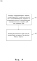
- a method for antenna sharing in a radar transceiver, such as the radar transceiver according to the first aspect of the invention.
- the method comprises a step of coupling an electrical balance duplexer comprising a hybrid transformer network and a non-tunable balancing impedance to a transmission node of a transmission path, a reception node of a reception path, and an antenna node.
- the method further comprises a step of isolating the transmission path from the reception path by means of the electrical balance duplexer.
- the non-tunable balancing impedance is configured to provide a fixed impedance value that is defined corresponding to an impedance value at the antenna node.
- the radar system according to the second aspect and the method according to the third aspect correspond to the radar transceiver according to the first aspect and its implementation forms. Accordingly, the radar system of the second aspect and the method of the third aspect achieve the same advantages and effects as the radar transceiver of the first aspect and its respective implementation forms.
- a first exemplary embodiment of the radar transceiver 100 according to the first aspect of the invention is illustrated.
- the radar transceiver 100 comprises a signal generation and control unit (SGC) 101 comprising a chirp signal generator or a chirp generator or a frequency synthesizer 102, and additional control circuitry to generate a transmit signal 103.
- the generation and/or control of said transmit signal 103 may include any known techniques or entities such as a signal synthesis chain that may comprise a full chirping phase-locked loop, frequency multipliers, signal splitters and amplification modules.
- the radar transceiver 100 further comprises an amplifier, especially a power amplifier (PA) 104, that is coupled to a transmission node 106. Hence, the PA 104 amplifies the transmit signal 103, thereby generating an amplified transmit signal 105 and feeds the amplified transmit signal 105 at the transmission node 106.
- PA power amplifier
- the transmission path of the radar transceiver 100 comprises the signal generator 102, the PA 104, and optionally the SGC 101.
- the radar transceiver 100 further comprises an electrical balance duplexer (EBD) 109.
- the EBD 109 comprises a hybrid transformer network including a primary winding or coil 110 and a secondary winding or coil 111, and a non-tunable balancing impedance 112.
- the non-tunable balancing impedance 112 is further coupled to a ground potential 113.
- the EBD 109 is coupled to the transmission node 106, to an antenna node 107, and to a reception node 108.
- the primary winding 110 of the hybrid transformer network is coupled to the antenna node 107, to the transmission node 106, and to the non-tunable balancing impedance 112, so as to split the PA 104 output between an impedance at the antenna node 107 and the non-tunable balancing impedance 112.
- the secondary winding 111 of the hybrid transformer network is coupled to the reception node 108.
- the hollow circles on the primary winding 110 and the secondary winding 111 of the hybrid transformer network denote the coupling directions.
- the non-tunable balancing impedance 112 is specifically designed to represent a fixed impedance value across frequency such that a resulting spillover component or signal 123, especially from the transmission path to the reception path through the EBD 109 across the frequency be at least lower than a required value, e.g. 20dB.
- the radar transceiver 100 comprises an antenna 121 coupled to the antenna node 107, through which the transmission path may transmit the transmit signal 103 resp. the amplified transmit signal 105.
- the transmitted signal is normally reflected from all targets and the resulting echo or reflected signal or antenna signal 122 is received by the antenna 121. Generally, only a portion of the transmitted signal is reflected back to the antenna 121.
- the radar transceiver 100 further comprises an amplifier, especially a low noise amplifier (LNA) 114, that amplifies the antenna signal 122, thereby generating a radar receive signal 115.
- a mixer especially a frequency mixer 116 downstream to the LNA 114 demodulates the radar receive signal 115 with a carrier signal LO IN generated by the signal generator 102, especially by a local oscillator of the SGC 101, that is provided at a local oscillator input 117 of the mixer 116.
- the direct conversion of the radar receive signal 115 at the mixer 116 results in a baseband signal 118.
- the radar transceiver 100 further comprises a high-pass filter (HPF) 119 downstream to the mixer 116 and filters the baseband signal 118, thereby generates a filtered baseband signal 120 or an analog baseband signal 120.
- HPF high-pass filter
- the reception path of the radar transceiver 100 comprises the LNA 114, the mixer 116, and the HPF 119, that form the analog baseband section of the reception path of the radar transceiver 100.
- a second exemplary embodiment of the radar transceiver 200 according to the first aspect of the invention is illustrated.
- the radar transceiver 200 differs from the radar transceiver 100 in that the radar transceiver 200 further comprises a delay circuit, especially a tunable delay circuit 201 that is coupled in-between the signal generator 102 and the local oscillator input 117 of the mixer 116.
- the delay circuit 201 receives the transmit signal 103 from the SGC 101 resp. the signal generator 102, and further delays, especially in time, the transmit signal 103, thereby generating a delayed version of the transmit signal 202.
- the delayed version of the transmit signal 202 is then provided at the local oscillator input 117 of the mixer 119 as the carrier signal LO IN to demodulate the radar receive signal 115.
- the amount of delay introduced by the delay circuit 201 may correspond to the delay causing the spillover component or signal 123 to reach the receiving path through the EBD 109.
- the spillover signal 123 can be moved to lower intermediate frequencies (IF), i.e. in a zero-IF configuration closer to 0 Hz after frequency conversion, which allows for a more compact HPF 119 and/or less rejection in the EBD 109, freeing up a further degree of freedom in the system design.
- IF intermediate frequencies
- the spillover component resulting at the receiving path especially at the reception node 108, only needs to avoid compression, while the overall chain of the EBD 109 and the HPF 119 can achieve sufficient spillover suppression i.e. in order to enable proper target detection in a subsequent radar signal processing chain after analog-to-digital conversion, or instead by an inference-based signal processor.
- the delay circuit 201 may further be tuned or be configured to introduce a delay, especially in time, so as to mimic a delay in the incoming echo resp. the antenna signal 122. This is particularly advantageous in such cases where the transmitted signal is effectively rebounding off a nearby object such as the radome or a bumper in automotive applications, and the delay is tuned to mimic that echo's delay through the full back-and-forth chain.
- a third exemplary embodiment of the radar transceiver 300 according to the first aspect of the invention is illustrated.
- the radar transceiver 300 comprises, in addition to the radar transceiver 200, a switch-control circuit (SWC) 302, a first switch 304 coupled across the non-tunable balanced impedance 112, and a second switch 305 coupled in-between the non-tunable balanced impedance 112 and the ground potential 113.
- the SWC 302 generates control signals 303 to simultaneously operate the first switch 304 and the second switch 305.
- the SGC 101 may generate control commands 301 for the SWC 302 and/or configure the SWC 302 in order to generate the control signals 303.
- the switching of the first switch 304 and the second switch 305 facilitates the radar transceiver 300 to be operated in a first operation mode, hereinafter referred as full-duplex (FD) mode, a second operation mode, hereinafter referred as reception-only (RX-only) mode, and a third operation mode, hereinafter referred as transmission-only (TX-only) mode.
- FD full-duplex
- RX-only reception-only
- TX-only transmission-only
- the SWC 302 opens the first switch 304 and closes the second switch 305.
- the non-tunable balanced impedance 112 is therefore coupled to the primary winding 110 as well as to the ground potential.
- the EBD 109 operates normally to isolate the transmission path from the reception path.
- the antenna impedance Z ANT equals the impedance of the non-tunable balanced impedance 112 Z BAL at the transmission frequency
- the electrical signals splits up exactly between the two impedances, i.e., perfect common-mode to the hybrid transformer.
- a reduced net differential current flows through the primary winding 110 of the hybrid transformer, and only the common-mode leakage, especially for a differential arrangement of the reception path, as the spillover signal 123 transfers through to the hybrid transformer secondary side 111, cancelling any direct-path transmission path leakage flowing into the reception path.
- the antenna signal 122 While receiving via the antenna 122, the antenna signal 122 is not excited in the non-tunable balanced impedance 112.
- a differential current flows through the hybrid transformer and is transferred to the reception node 108 of the reception path. Since the signals are evenly distributed to the Z ANT and Z BAL , there is inherit a minimal insertion loss of 3 dB.
- the SWC 302 closes the first switch 304 and the second switch 305.
- the non-tunable balanced impedance 112 is completely bypassed to the ground potential.
- the SGC 101 may stop generating and/or transmitting the transmit signal 103 during the RX-only mode, thereby effectively turning off the transmission operation along the transmission path during the RX-only mode.
- the hybrid transformer network acts as a balun during the RX-only mode, which effectively avoids the inherit signal-splitting insertion loss of the EBD 109.
- the SWC 302 opens the first switch 304 and the second switch 305.
- the non-tunable balanced impedance 112 is completely disconnected or isolated from the hybrid transformer network of the EBD 109.
- a fourth exemplary embodiment of the radar transceiver 400 according to the first aspect of the invention is illustrated.
- the radar transceiver 400 comprises, in addition to the radar transceiver 300, a third switch 401 coupled in-between the reception node 108 and the input of the LNA 114.
- the SWC 302 generates control signals 303 to simultaneously operate the first switch 304, the second switch 305, and the third switch 401.
- the SGC 101 may generate control commands 301 for the SWC 302 and/or configure the SWC 302 in order to generate the control signals 303.
- the switching of the first switch 304, the second switch 305, and the third switch 401 facilitates the radar transceiver 300 to be operated in the full-duplex (FD) mode, the reception-only (RX-only) mode, and the transmission-only (TX-only) mode.
- FD full-duplex
- RX-only reception-only
- TX-only transmission-only
- the SWC 302 opens the first switch 304, and closes the second switch 305 and the third switch 401.
- the non-tunable balanced impedance 112 is therefore coupled to the primary winding 110 as well as to the ground potential.
- the EBD 109 operates normally to isolate the transmission path from the reception path.
- the antenna impedance Z ANT equals the impedance of the non-tunable balanced impedance 112 Z BAL at the transmission frequency, the electrical signals splits up exactly between the two impedances, i.e., perfect common-mode to the hybrid transformer.
- the signal split factor may not exactly be 50-50 in some embodiments, which implies trading off loss for isolation. This is also referred to as the skewing of the hybrid transformer. Note that such a skewing factor can also be introduced by providing an impedance value that by design is offset from the antenna impedance as part of the design of the electrical-balance duplexer.
- a reduced net differential current flows through the primary winding 110 of the hybrid transformer, and only the common-mode leakage as the spillover signal 123 transfers through to the hybrid transformer secondary side 111, cancelling any direct-path transmission path leakage flowing into the reception path.
- the antenna signal 122 While receiving via the antenna 122, the antenna signal 122 is not excited in the non-tunable balanced impedance 112.
- a differential current flows through the hybrid transformer and is transferred to the reception node 108 of the reception path. Since the signals are evenly distributed to the Z ANT and Z BAL , there is inheritly a minimal insertion loss of 3 dB.
- the SWC 302 closes the first switch 304, the second switch 305, and the third switch 401.
- the non-tunable balanced impedance 112 is completely bypassed to the ground potential.
- the SGC 101 may stop generating and/or transmitting the transmit signal 103 during the RX-only mode, thereby effectively turning off the transmission operation along the transmission path during the RX-only mode.
- the hybrid transformer network acts as a balun during the RX-only mode, thereby effectively avoiding the inherit signal-splitting insertion loss of the EBD 109.
- the SWC 302 opens the first switch 304, the second switch 305, and the third switch 401.
- the non-tunable balanced impedance 112 is completely disconnected or isolated from the hybrid transformer network of the EBD 109.
- the reception path is isolated from the transmission path. Consequently, the isolation between the transmission path and the reception path is drastically improved whereby providing only one signal transmission path from the transmission node 106 to the antenna node 107.
- the inherit insertion loss of the EBD 109 is also effectively avoided.
- FIG. 5 an exemplary embodiment of a radar system 500 according to the second aspect of the invention is illustrated.
- the radar system comprises a baseband processing unit (BPU) 501 that provides signal generation control to a signal generator or frequency synthesizer 502 in order to generate a transmit signal 503.
- the BPU 501 further performs baseband processing in the analog and/or digital domain.
- the radar system 500 further comprises a first radar transceiver and a second radar transceiver, where each of the transceivers may correspond to the radar transceivers 100, 200, 300, 400 according to the first aspect of the invention.
- the first radar transceiver comprises a first transmission block 506 downstream to the signal generator 502 that may include a power amplifier.
- the output of the first transmission block 506 is coupled to a first transmission node 508.
- the radar system 500 further comprises a first EBD 510 that is coupled to the first transmission node 508, to a first antenna node 512, and to a first reception node 516.
- a first antenna 514 may be coupled to the first antenna node 512.
- the radar system 500 may optionally comprise a first LNA (not shown).
- the output of the LNA (or the first reception node 516 if the LNA is not present) is coupled to a first analog baseband processing block that may comprise a first frequency mixer 518 and a first HPF 520.
- the first HPF 520 may generate a filtered analog baseband signal for post-processing.
- the radar system 500 may additionally comprise a first delay circuit, especially a tunable delay circuit 504, coupled in-between the signal generator 502 and the first mixer 518 to provide a delayed version of the transmit signal 503 at the first mixer 518 as a local oscillator input signal.
- the radar system 500 further comprises a second radar transceiver that comprises a first transmission block 507 downstream to the signal generator 502, which may include a power amplifier.
- the output of the second transmission block 507 is coupled to a second transmission node 509.
- the radar system 500 further comprises a second EBD 511 that is coupled to the second transmission node 509, to a second antenna node 513, and to a second reception node 517.
- a second antenna 515 may be coupled to the second antenna node 513.
- the radar system 500 may optionally comprise a second LNA (not shown).
- the output of the LNA (or the second reception node 517 if the LNA is not present) is coupled to a second analog baseband processing block that may comprise a second frequency mixer 519 and a second HPF 521.
- the second HPF 521 may generate a filtered analog baseband signal for post-processing.
- the radar system 500 may additionally comprise a second delay circuit, especially a tunable delay circuit 505, coupled in-between the signal generator 502 and the second mixer 519 to provide a delayed version of the transmit signal 503 at the second mixer 519 as a local oscillator input signal.
- the BPU 501 may optionally comprise the SGC 101 as illustrated along Figs. 1-4 in order to generate and to provide control for signal generation.
- the SGC 101 may be implemented external to the BPU 501.
- the BPU 501 may comprise, for example, analog to digital converters for domain conversion of the respective analog baseband signals, a range processing block for radar range processing, and a discrete Fourier transformation (DFT) block for producing Doppler profiles.
- DFT discrete Fourier transformation
- the BPU 501 may be implemented by hardware, software, or any combination thereof. Furthermore, additional means for generating and/or processing radar signals, e.g. memory or storage for storing control commands, as well as interfaces such as user interface, are not explicitly shown but are apparent from the above-described implementation.
- the first radar transceiver is operable in the FD-mode or in the RX-only mode or in the TX-only mode.
- the second radar transceiver is operable in the FD-mode or in the RX-only mode or in the TX-only mode.
- the number of radar transceivers is not limited by the presented example and can be selected based on a desired size of a virtual array to be formed out of the physical antenna array of the radar system 500, which will be described in the later section of the description.
- Fig. 6 the effect of a tunable delay, especially realized on the tunable delay circuit 201, 504, 505 described above, on spillover rejection is illustrated by way of an example.
- the first segment 601 at the top-left illustrates the spillover level at the baseband, i.e. at the receiver output, when the tunable delay circuit 201, 504, 505 is implemented.
- the horizontal axis denoted the frequency in kHz and the vertical axis denotes IF magnitude in dBm.
- the second segment 602 at the top-right illustrates the spillover level at the baseband, i.e. at the receiver output, when the tunable delay circuit 201, 504, 505 is not included in the delay chain.
- the horizontal axis denoted the frequency in kHz and the vertical axis denotes IF magnitude in dBm.
- the filter profile 603 of the HPF 119, 520, 521 shows different delays at different instances over frequency, where the horizontal axis denotes frequency in kHz and the vertical axis denotes filter gain in dB. It is therefore conceivable that, for a given delay of 300ps provided by the tunable delay circuit 201, 504, 505, the spillover level at the baseband is advantageously reduced by 15dB.
- R MAX P TX G TX G RX ⁇ 2 ⁇ P RX 4 ⁇ 3 4 where P TX , G TX , G RX , ⁇ , ⁇ , P RX are transmitted power, TX and RX antenna gain, wavelength, and radar cross section, respectively.
- radar can estimate the angle of arrival with multiple TX or RX antennas by digital receiver-side beamforming.
- the maximum detectable ⁇ is +/- 90°, which can be achieved with the physical antenna distance of ⁇ /2.
- ⁇ can be finely resolved by the number of antennas, N, 2n/N.
- antenna resolution, ⁇ with d of A/2 and a bore sight view (8 0)
- ⁇ RES 2 N rad
- MIMO radar technology is a way to optimize the number of antennas to improve the angular resolution.
- a 2x2 MIMO can achieve the equivalent angle resolution of 1x4 SIMO.
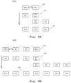
- exemplary antenna configurations for conventional SIMO and MIMO techniques are illustrated. Especially, a 1x4 SIMO antenna configuration is shown at the top and a 2x2 MIMO antenna configuration is shown at the bottom.
- receivers RX can detect with a phase difference ( ⁇ ) array, [0 ⁇ ], with the first transmitter TX1.
- ⁇ phase difference
- the receivers RX can detect with another ⁇ array, [2 ⁇ 3 ⁇ ], with the second transmitter TX2. Therefore, finally 4-virtual phase array, [0 ⁇ 2 ⁇ 3 ⁇ ], equivalent to 1x4 SIMO physical array, as shown in the top of Fig. 7 .
- the horizontal arrow below the TXs and RXs of the MIMO configuration indicates the time instance or dimension for a time-division multiplexing operation of the TXs-RXs.
- MIMO requires 4 antennas, but 5 for SIMO.
- SIMO requires 1+N antennas, but MIMO requires M+N/M antennas, where M and N/M are the number of transmitter and receiver antennas, respectively.
- FIG. 8A Fig. 8A
- Fig. 8B Fig. 8C
- different arrangements of an antenna array of the radar system 500 are illustrated.
- an antenna array 800A especially a physical antenna array in one-dimension, of the radar system 500 with two radar transceivers TRX1, TRX2 is illustrated.
- the physical array 801 is formed by physically separating the radar transceivers by a spacing at least of ⁇ /2, where A is the free-space wavelength, in order to avoid any mutual coupling.
- the radar transceivers TRX1, TRX2 are configured to be operated in the FD mode and/or in the RX-only mode, thereby forming a 2x2 MIMO physical array.
- the TRX1 operates in the FD mode and the TRX2 operates in the RX-only mode. Consequently, in a second time instance, the TRX1 operates in the RX-only mode and the TRX2 operates in the FD mode.
- the timing instance or dimension is shown by the downward vertical arrow, for example.
- the RXs can detect with a phase difference ( ⁇ ) array, [- ⁇ 0], with the first TX at the second transceiver TRX2.
- an antenna array 800B especially a physical antenna array in one-dimension, of the radar system 500 with four radar transceivers is illustrated.
- the physical array 804 is formed by physically separating the radar transceivers by a spacing at least of ⁇ /2.
- two of the radar transceivers are configured to be operated in the FD-mode and two of the radar transceivers are configured to be operated in the RX-only mode, thereby forming a 2x4 MIMO physical array.
- the TRX1 operates in the FD mode and the rest of the transceivers operate in the RX-only mode. Consequently, in a second time instance, the TRX2 operates in the FD mode and the rest of the transceivers operate in the RX-only mode.
- the timing instance or dimension is shown by the downward vertical arrow, for example.
- the RXs can detect with a phase difference ( ⁇ ) array, [-3 ⁇ -2 ⁇ - ⁇ 0], with the first TX at the second transceiver TRX2. Since the TRX2 and TRX1 are as far apart as d, another ⁇ array of [0 ⁇ 2 ⁇ 3 ⁇ ], with the second TX at the first transceiver TRX1.
- an antenna array 800C especially a physical antenna array in two-dimension, of the radar system 500 with four radar transceivers is illustrated.
- the physical array 807 is formed by physically separating the radar transceivers, especially along two-dimension (2D) by a spacing at least of ⁇ /2.
- two of the radar transceivers are configured to be operated in the FD-mode and two of the radar transceivers are configured to be operated in the RX-only mode, thereby forming a 2x4 MIMO physical array.
- the 2D arrangement of the 2x4 MIMO antenna array is capable of performing both azimuth and elevation estimation as well as azimuth only.
- the TRX1 operates in the FD mode and the rest of the transceivers operate in the RX-only mode. Consequently, in a second time instance, the TRX2 operates in the FD mode and the rest of the transceivers operate in the RX-only mode.
- the timing instance or dimension is shown by the downward vertical arrow, for example.
- the transceivers may exchange their operation modes or use different operation modes, e.g. the RXs may operate in the TX-only mode, which may result in different MIMO antenna configurations.
- an electrical balance duplexer comprising a hybrid transformer network and a non-tunable balancing impedance is coupled to a transmission node of a transmission path, a reception node of a reception path, and the antenna node.
- the transmission paths is isolated from the reception path by means of the electrical balance duplexer.
- the invention proposes a radar transceiver with sharing antennas for both transmitter and receiver, and a MIMO radar comprising a plurality of said radar transceivers.
- the proposed electrical balance duplexer is advantageously operable in the form of a transformable duplexer/balun, which allows for achieving the afore-mentioned effect.
- the invention may bring the benefit to compact the system form factor, especially for MIMO radars, such as UWB MIMO radars.
Landscapes
- Engineering & Computer Science (AREA)
- Computer Networks & Wireless Communication (AREA)
- Physics & Mathematics (AREA)
- General Physics & Mathematics (AREA)
- Radar, Positioning & Navigation (AREA)
- Remote Sensing (AREA)
- Signal Processing (AREA)
- Radar Systems Or Details Thereof (AREA)
Abstract
Description
- The invention relates to a radar transceiver with antenna sharing technique, especially for multiple-input-multiple-output (MIMO) frequency modulated continuous wave (FMCW) radars.
- Generally, among other things, an electrical balance duplexer (EBD) may be used to isolate a transmitter and a receiver and enable them to share a common antenna. In typical full-duplex operation, i.e. the simultaneous operation of both the transmitter and the receiver, the EBD's balance network is required to be tuned to achieve very high spillover rejection, i.e. to minimize the direct leakage in the EBD. This needs to be done to ensure the receiver is not desensitized as a result of said transmitter spillover. Said tuning is generally cumbersome, may involve either heavy algorithmic adaptive programming of a complex impedance network, e.g. high-dimensional genetic algorithms, multi-layer optimization techniques, heavy reliance on heuristics, or may require additional hardware, e.g. to sense the antenna impedance in order to optimize the balance network with simpler algorithms.
- Furthermore, the balance network in typical implementations may consist of several complex tuning structures that are silicon-area intensive. Because of the fact the balance network needs to sustain half of the transmitter energy under load, switched-component devices with multiple stacked transistor-based switch devices are used to avoid switch breakdown or the addition of significant nonlinearity products in the receiver path, due to nonlinear switch behavior. Additionally, EBDs typically achieve a high spillover rejection, e.g. more than 50 dB, in a very narrow bandwidth. This is because the antenna-versus-balance network impedance balance can be maintained to such high accuracy only for a single frequency.
- For example, the document
US 2020/0209349 A1 presents a radar circuitry that includes an electrically balanced duplexer as an isolator that isolates a transmission signal path and a reception signal path. Said electrically balanced duplexer is provided with a variable impedance tuner that includes processor circuitry in order to sense and further to adjust the impedance at the balance network to match the impedance of the antenna. - Accordingly, an object of the invention is to provide a radar transceiver, a radar system, and a method that can address the aforementioned limitations.
- The object is solved by the features of the first independent claim for the radar transceiver, by the features of the second independent claim for the radar system, and by the features of the third independent claim for the method. The dependent claims contain further developments.
- According to a first aspect of the invention, a radar transceiver is provided. The radar transceiver comprises an electrical balance duplexer coupled to a transmission node of a transmission path, a reception node of a reception path, and an antenna node, and is configured to isolate the transmission path from the reception path. The electrical balance duplexer comprises a hybrid transformer network and a non-tunable balancing impedance. In this regard, the non-tunable balancing impedance is configured to provide a fixed impedance value that is defined corresponding to an impedance at the antenna node.
- Therefore, the invention proposes an antenna sharing technique in a radar transceiver by means of a pre-operation-tuned electrical balance duplexer with its balancing impedance preferably realized in the form of a balance network that may comprise resistive elements and/or inductive elements and/or capacitive elements, and is pre-tuned or is predefined to a fixed impedance value corresponding to an impedance value anticipated at the antenna node. A design method may be employed including insitu measurements of the impedance of the antenna device employed at the antenna node, in order to enable design of the fixed impedance value to provide optimized balance condition across frequency for the nominal antenna conditions.
- Moreover, the non-tunable balancing impedance, especially the impedance of said non-tunable balancing impedance may be defined based on the design trade-offs of the hybrid transformer network of the electrical balance duplexer, e.g. isolation, loss, coupling, and the like. This advantageously solves the problems associated with the conventional impedance-tuning schemes of an electrical balance duplexer.
- Preferably, the radar transceiver further comprises an antenna coupled to the antenna node, whereby the impedance value at the antenna node corresponds to an impedance of the antenna. Advantageously, by explicitly not tuning the electrical balance duplexer and by co-designing the non-tunable balancing impedance together with the antenna impedance, which is assumed known a-priori to the chip design, a sufficiently high spillover rejection can be achieved whereby avoiding the complexities associated with impedance-tuning and enabling a balance impedance structure with reduced physical dimensions compared to a tunable counterpart.
- Preferably, the transmission path comprises a signal generator followed by a power amplifier, whereby an output of the power amplifier is coupled to the transmission node. In addition, the reception path comprises a low-noise amplifier followed by a mixer followed by a high-pass filter, whereby an input of the low-noise amplifier is coupled to the reception node.
- Alternatively, the reception path may comprise a mixer followed by a high-pass filter, whereby an input of the mixer is coupled to the reception node. Advantageously, by implementing the high-pass filter in the analog baseband section along with the proposed electrical balance duplexer, especially providing said high-pass filter downstream to the electrical balance duplexer along the reception path, a high spillover suppression can be achieved along the reception path in order to avoid sidelobes in the range-Doppler response of the radar.
- In particular, the high-pass filter and the isolation from the proposed electrical balance duplexer jointly suppress any self-interference, i.e. interference caused by the radar transmission path, especially according to a permissible limit across the required or operating bandwidth.
- Preferably, the transmission path is configured to generate a transmit signal and further to transmit the transmit signal via the hybrid transformer network and the antenna. Additionally, the reception path is configured to receive an antenna signal indicative of an incoming echo, through electromagnetic transduction, e.g. from an object or target, or from a neighboring or a further antenna, or rebounding off a nearby object such as the radar radome, corresponding to the transmit signal via the antenna and the hybrid transformer network.
- Preferably, the radar transceiver further comprises a delay circuit, preferably a tunable delay circuit, coupled between the signal generator and a local oscillation signal input of the mixer. The delay circuit is configured to delay the transmit signal, by a pre-defined amount or by a tunable amount, thereby providing a delayed version of the transmit signal to the local oscillation signal input of the mixer.
- In this regard, the delay may correspond to a delay of a spillover signal from the transmission path to the reception path, especially through the electrical balance duplexer, e.g. through the hybrid transformer network of the electrical balance duplexer. Additionally or alternatively, the delay may correspond to a delay or delays in the antenna signal, which may in turn correspond to a specific unwanted echo, e.g. from the radome, or from a second radar transmitter if the radar is configured as an array of similar antenna-transmitter-receiver structures.
- Hence, the tunable delay in the local oscillator chain may help to tune the local oscillator signal delay value prior to mixing with a delay in the spillover path from the transmission path to the reception path. Advantageously, the spillover signal can be moved to lower frequencies, which allows for a compact design of the high-pass filter and/or reduced requirements for the spillover rejection in the electrical balance duplexer.
- Preferably, the signal generator comprises or is a frequency sweep generator and wherein the transmit signal comprises or is a swept-frequency signal. In other words, the signal generator may be a chirp signal generator and the transit signal may be a chirp signal, especially with a series of chirps with various ramps and frequencies. Furthermore, a bandwidth of said chirp signal may be selected or may be defined based on a desired or required range resolution of the radar or vice versa. The signal generator may operate at a scaled-down frequency compared to the RF operating frequency, and may comprise one or multiple frequency multipliers in order to optimize power consumption and/or other system parameters.
- Preferably, the radar transceiver further comprises a first switch coupled across the non-tunable balanced impedance, a second switch coupled in-between the non-tunable balanced impedance and a ground potential, and a switch-control circuit configured to operate the first switch and the second switch simultaneously.
- In addition, the radar transceiver is configured to be operated in a first operation mode, a second operation mode, and a third operation mode. In this regard, the switch-control circuit is configured to open the first switch, and to close the second switch during the first operation mode, to close the first switch and the second switch during the second operation mode, and to open the first switch and the second switch during the third operation mode.
- For instance, the first operation mode may correspond to a full-duplex mode, the second operation mode may correspond to a reception-only mode, and the third operation mode may correspond to a transmission-only mode.
- Advantageously, by means of the first switch, the second switch, and the switching control, the radar transceiver can be operated in the full-duplex mode, the reception-only mode, and the transmission-only mode, where said modes can be switched from one another when needed.
- Furthermore, the switching of said switches further allows the fixed balancing impedance of the electrical balance duplexer to be bypassed or to be grounded or to be disconnected from the electrical balance duplexer, thereby facilitating a duplexer-balun transformable transformer network.
- Preferably, the radar transceiver further comprises a third switch coupled in-between the reception node and the input of the low-noise amplifier, and wherein the switch-control circuit is configured to operate the first switch, the second switch, and the third switch simultaneously.
- Alternatively, the low-noise amplifier may comprise of a transistor device that can be operated as such a third switch, to open the receiver-side winding of the hybrid transformer.
- In this regard, the switch-control circuit is configured to open the first switch, and to close the second switch and the third switch during the first operation mode, to close the first switch, the second switch, and the third switch during the second operation mode, and to open the first switch, the second switch, and the third switch during the third operation mode.
- Advantageously, by means of the first switch, the second switch, the third switch, and the switching control, the radar transceiver can be operated in the full-duplex mode, the reception-only mode, and the transmission-only mode, where said modes can be switched from one another when needed.
- Furthermore, the switching of the first switch and the second switch further allows the fixed balancing impedance of the electrical balance duplexer to be bypassed or to be grounded or to be disconnected from the electrical balance duplexer, thereby facilitating a duplexer-balun transformable transformer network in reception-only mode. In this mode, the power amplifier may comprise of a transistor output device that can be configured to provide a high impedance at its output node such that the balun transformer network operates with low loss.
- Moreover, the switching of the third switch, especially during the transmission-only mode, advantageously mitigates the inherit insertion loss caused by signal splitting in the hybrid transformer network of the electrical balance duplexer.
- It is to be noted that, explicitly, the first switch, the second switch, and the third switch are for mode control only as described above, and are not intended for dynamic operation such as could be required in an adaptively tuned electrical-balance duplexer.
- Preferably, the transmission path and the reception path comprise or are single-ended transmission lines and/or connections. Alternatively, the reception path comprises or are differential transmission lines, devices, and/or connections.
- It is also conceivable that the electrical balance duplexer may be inversely connected with respect to the transmitter node and the receiver node, i.e. connecting the low-noise amplifier or mixer to a primary winding, especially a center-tap on the primary winding, of the hybrid transformer which is connected to the antenna and balancing network, and a power amplifier to a secondary winding of the hybrid transformer. In that case, the transmission path may comprise single-ended or differential transmission lines, devices and/or connections as well. In such an embodiment, switches as described prior may similarly be employed to devise full-duplex, transmit-only or receive-only operation modes. Advantageously, for example, the flexibility in system design is improved while otherwise maintaining the same concepts and benefits of the proposed system.
- Preferably, the electrical balance duplexer is a wideband electrical balance duplexer, more preferably having an operating bandwidth of or more than 500 MHz. Therefore, ultra-wideband (UWB) technologies are advantageously facilitated for the proposed radar transceiver.
- According to a second aspect of the invention, a radar system is provided. The radar system comprises a plurality of radar transceivers according to the first aspect of the invention, wherein the radar transceivers are arranged in a one-dimensional array or in a two-dimensional array. Preferably, each of the plurality of radar transceivers is configured to be operated in the first operation mode or in the second operation mode or in the third operation mode. Advantageously, a MIMO radar system based on the proposed radar transceiver is provided.
- According to a third aspect of the invention, a method is provided for antenna sharing in a radar transceiver, such as the radar transceiver according to the first aspect of the invention. The method comprises a step of coupling an electrical balance duplexer comprising a hybrid transformer network and a non-tunable balancing impedance to a transmission node of a transmission path, a reception node of a reception path, and an antenna node. The method further comprises a step of isolating the transmission path from the reception path by means of the electrical balance duplexer. In this regard, the non-tunable balancing impedance is configured to provide a fixed impedance value that is defined corresponding to an impedance value at the antenna node.
- It is to be noted that the radar system according to the second aspect and the method according to the third aspect correspond to the radar transceiver according to the first aspect and its implementation forms. Accordingly, the radar system of the second aspect and the method of the third aspect achieve the same advantages and effects as the radar transceiver of the first aspect and its respective implementation forms.
- Exemplary embodiments of the invention are now further explained with respect to the drawings by way of example only, and not for limitation. In the drawings:
- Fig. 1
- shows a first exemplary embodiment of the radar transceiver according to the first aspect of the invention;
- Fig. 2
- shows a second exemplary embodiment of the radar transceiver according to the first aspect of the invention;
- Fig. 3
- shows a third exemplary embodiment of the radar transceiver according to the first aspect of the invention;
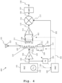
- Fig. 4
- shows a fourth exemplary embodiment of the radar transceiver according to the first aspect of the invention;
- Fig. 5
- shows an exemplary embodiment of the radar system according to the second aspect of the invention;
- Fig. 6
- shows the effect of the tunable delay on spillover rejection by way of an example;
- Fig. 7
- shows exemplary antenna configurations for conventional SIMO and MIMO techniques;
- Fig. 8A
- shows a first exemplary arrangement of an antenna array of the radar system;
- Fig. 8B
- shows a second exemplary arrangement of an antenna array of the radar system;
- Fig. 8C
- shows a third exemplary arrangement of an antenna array of the radar system; and
- Fig. 9
- shows an exemplary embodiment of the method according to the third aspect of the invention.
- Reference will now be made in detail to the embodiments of the present invention, examples of which are illustrated in the accompanying drawings. However, the following embodiments of the present invention may be variously modified and the range of the present invention is not limited by the following embodiments. Reference signs for similar entities in different embodiments are partially omitted.
- In
Fig. 1 , a first exemplary embodiment of theradar transceiver 100 according to the first aspect of the invention is illustrated. - The
radar transceiver 100 comprises a signal generation and control unit (SGC) 101 comprising a chirp signal generator or a chirp generator or afrequency synthesizer 102, and additional control circuitry to generate a transmitsignal 103. The generation and/or control of said transmitsignal 103 may include any known techniques or entities such as a signal synthesis chain that may comprise a full chirping phase-locked loop, frequency multipliers, signal splitters and amplification modules. Theradar transceiver 100 further comprises an amplifier, especially a power amplifier (PA) 104, that is coupled to atransmission node 106. Hence, thePA 104 amplifies the transmitsignal 103, thereby generating an amplified transmitsignal 105 and feeds the amplified transmitsignal 105 at thetransmission node 106. - Therefore, the transmission path of the
radar transceiver 100 comprises thesignal generator 102, thePA 104, and optionally theSGC 101. - The
radar transceiver 100 further comprises an electrical balance duplexer (EBD) 109. TheEBD 109 comprises a hybrid transformer network including a primary winding orcoil 110 and a secondary winding orcoil 111, and anon-tunable balancing impedance 112. Thenon-tunable balancing impedance 112 is further coupled to aground potential 113. TheEBD 109 is coupled to thetransmission node 106, to anantenna node 107, and to areception node 108. Preferably, the primary winding 110 of the hybrid transformer network is coupled to theantenna node 107, to thetransmission node 106, and to thenon-tunable balancing impedance 112, so as to split thePA 104 output between an impedance at theantenna node 107 and thenon-tunable balancing impedance 112. The secondary winding 111 of the hybrid transformer network is coupled to thereception node 108. - The hollow circles on the primary winding 110 and the secondary winding 111 of the hybrid transformer network denote the coupling directions. The
non-tunable balancing impedance 112 is specifically designed to represent a fixed impedance value across frequency such that a resulting spillover component or signal 123, especially from the transmission path to the reception path through theEBD 109 across the frequency be at least lower than a required value, e.g. 20dB. - Preferably, the
radar transceiver 100 comprises anantenna 121 coupled to theantenna node 107, through which the transmission path may transmit the transmitsignal 103 resp. the amplified transmitsignal 105. The transmitted signal is normally reflected from all targets and the resulting echo or reflected signal orantenna signal 122 is received by theantenna 121. Generally, only a portion of the transmitted signal is reflected back to theantenna 121. - The
radar transceiver 100 further comprises an amplifier, especially a low noise amplifier (LNA) 114, that amplifies theantenna signal 122, thereby generating a radar receivesignal 115. A mixer, especially afrequency mixer 116 downstream to theLNA 114 demodulates the radar receivesignal 115 with a carrier signal LOIN generated by thesignal generator 102, especially by a local oscillator of theSGC 101, that is provided at alocal oscillator input 117 of themixer 116. Hence, the direct conversion of the radar receivesignal 115 at themixer 116 results in abaseband signal 118. Theradar transceiver 100 further comprises a high-pass filter (HPF) 119 downstream to themixer 116 and filters thebaseband signal 118, thereby generates a filteredbaseband signal 120 or ananalog baseband signal 120. - Hence, the reception path of the
radar transceiver 100 comprises theLNA 114, themixer 116, and theHPF 119, that form the analog baseband section of the reception path of theradar transceiver 100. - In
Fig. 2 , a second exemplary embodiment of theradar transceiver 200 according to the first aspect of the invention is illustrated. - The
radar transceiver 200 differs from theradar transceiver 100 in that theradar transceiver 200 further comprises a delay circuit, especially atunable delay circuit 201 that is coupled in-between thesignal generator 102 and thelocal oscillator input 117 of themixer 116. - The
delay circuit 201 receives the transmitsignal 103 from theSGC 101 resp. thesignal generator 102, and further delays, especially in time, the transmitsignal 103, thereby generating a delayed version of the transmitsignal 202. The delayed version of the transmitsignal 202 is then provided at thelocal oscillator input 117 of themixer 119 as the carrier signal LOIN to demodulate the radar receivesignal 115. - The amount of delay introduced by the
delay circuit 201 may correspond to the delay causing the spillover component or signal 123 to reach the receiving path through theEBD 109. By mimicking the delay and by using said delayed version of the transmitsignal 202 at themixer 116, thespillover signal 123 can be moved to lower intermediate frequencies (IF), i.e. in a zero-IF configuration closer to 0 Hz after frequency conversion, which allows for a morecompact HPF 119 and/or less rejection in theEBD 109, freeing up a further degree of freedom in the system design. Moreover, by using theHPF 119 in the analog baseband section and thedelay circuit 201 in the local oscillator chain, the spillover component resulting at the receiving path, especially at thereception node 108, only needs to avoid compression, while the overall chain of theEBD 109 and theHPF 119 can achieve sufficient spillover suppression i.e. in order to enable proper target detection in a subsequent radar signal processing chain after analog-to-digital conversion, or instead by an inference-based signal processor. - The
delay circuit 201 may further be tuned or be configured to introduce a delay, especially in time, so as to mimic a delay in the incoming echo resp. theantenna signal 122. This is particularly advantageous in such cases where the transmitted signal is effectively rebounding off a nearby object such as the radome or a bumper in automotive applications, and the delay is tuned to mimic that echo's delay through the full back-and-forth chain. - In
Fig. 3 , a third exemplary embodiment of theradar transceiver 300 according to the first aspect of the invention is illustrated. - The
radar transceiver 300 comprises, in addition to theradar transceiver 200, a switch-control circuit (SWC) 302, afirst switch 304 coupled across the non-tunablebalanced impedance 112, and asecond switch 305 coupled in-between the non-tunablebalanced impedance 112 and theground potential 113. Preferably, theSWC 302 generates control signals 303 to simultaneously operate thefirst switch 304 and thesecond switch 305. Alternatively, theSGC 101 may generate control commands 301 for theSWC 302 and/or configure theSWC 302 in order to generate the control signals 303. - In this regard, the switching of the
first switch 304 and thesecond switch 305 facilitates theradar transceiver 300 to be operated in a first operation mode, hereinafter referred as full-duplex (FD) mode, a second operation mode, hereinafter referred as reception-only (RX-only) mode, and a third operation mode, hereinafter referred as transmission-only (TX-only) mode. It is to be noted that the operation modes do not follow any sequential order and theradar transceiver 300 is only operable in one of the above operation modes at a given operation time or period. - During the FD mode, the
SWC 302 opens thefirst switch 304 and closes thesecond switch 305. By way of this, the non-tunablebalanced impedance 112 is therefore coupled to the primary winding 110 as well as to the ground potential. - Hence, the
EBD 109 operates normally to isolate the transmission path from the reception path. Particularly, when the transmit signal is transmitted, and the antenna impedance ZANT equals the impedance of the non-tunable balanced impedance 112 ZBAL at the transmission frequency, the electrical signals splits up exactly between the two impedances, i.e., perfect common-mode to the hybrid transformer. - As a result, a reduced net differential current flows through the primary winding 110 of the hybrid transformer, and only the common-mode leakage, especially for a differential arrangement of the reception path, as the
spillover signal 123 transfers through to the hybrid transformersecondary side 111, cancelling any direct-path transmission path leakage flowing into the reception path. While receiving via theantenna 122, theantenna signal 122 is not excited in the non-tunablebalanced impedance 112. As a result, a differential current flows through the hybrid transformer and is transferred to thereception node 108 of the reception path. Since the signals are evenly distributed to the ZANT and ZBAL, there is inherit a minimal insertion loss of 3 dB. - During the RX-only mode, the
SWC 302 closes thefirst switch 304 and thesecond switch 305. As a result, the non-tunablebalanced impedance 112 is completely bypassed to the ground potential. In addition to this, theSGC 101 may stop generating and/or transmitting the transmitsignal 103 during the RX-only mode, thereby effectively turning off the transmission operation along the transmission path during the RX-only mode. Hence, the hybrid transformer network acts as a balun during the RX-only mode, which effectively avoids the inherit signal-splitting insertion loss of theEBD 109. - During the TX-only mode, the
SWC 302 opens thefirst switch 304 and thesecond switch 305. As a result, the non-tunablebalanced impedance 112 is completely disconnected or isolated from the hybrid transformer network of theEBD 109. - The following table describes the individual switching operations and their respective effects:
Table: 1 Mode TX SW1 SW2 Splitting Loss FD On Open Closed 3 dB RX-only Off Closed Closed ~0 dB TX-only On Open Open ~0 dB - In
Fig. 4 , a fourth exemplary embodiment of theradar transceiver 400 according to the first aspect of the invention is illustrated. - The
radar transceiver 400 comprises, in addition to theradar transceiver 300, athird switch 401 coupled in-between thereception node 108 and the input of theLNA 114. Preferably, theSWC 302 generates control signals 303 to simultaneously operate thefirst switch 304, thesecond switch 305, and thethird switch 401. Alternatively, theSGC 101 may generate control commands 301 for theSWC 302 and/or configure theSWC 302 in order to generate the control signals 303. - In this regard, the switching of the
first switch 304, thesecond switch 305, and thethird switch 401 facilitates theradar transceiver 300 to be operated in the full-duplex (FD) mode, the reception-only (RX-only) mode, and the transmission-only (TX-only) mode. It is to be noted that the operation modes do not follow any sequential order and theradar transceiver 400 is only operable in one of the above operation modes at a given operation time or period. - During the FD mode, the
SWC 302 opens thefirst switch 304, and closes thesecond switch 305 and thethird switch 401. By way of this, the non-tunablebalanced impedance 112 is therefore coupled to the primary winding 110 as well as to the ground potential. Hence, theEBD 109 operates normally to isolate the transmission path from the reception path. Particularly, when the transmit signal is transmitted, and the antenna impedance ZANT equals the impedance of the non-tunable balanced impedance 112 ZBAL at the transmission frequency, the electrical signals splits up exactly between the two impedances, i.e., perfect common-mode to the hybrid transformer. - In view of imperfections in practical lay-out in the hybrid transformer, as well as a conscious design choice, the signal split factor may not exactly be 50-50 in some embodiments, which implies trading off loss for isolation. This is also referred to as the skewing of the hybrid transformer. Note that such a skewing factor can also be introduced by providing an impedance value that by design is offset from the antenna impedance as part of the design of the electrical-balance duplexer.
- As a result, a reduced net differential current flows through the primary winding 110 of the hybrid transformer, and only the common-mode leakage as the
spillover signal 123 transfers through to the hybrid transformersecondary side 111, cancelling any direct-path transmission path leakage flowing into the reception path. While receiving via theantenna 122, theantenna signal 122 is not excited in the non-tunablebalanced impedance 112. As a result, a differential current flows through the hybrid transformer and is transferred to thereception node 108 of the reception path. Since the signals are evenly distributed to the ZANT and ZBAL, there is inheritly a minimal insertion loss of 3 dB. - During the RX-only mode, the
SWC 302 closes thefirst switch 304, thesecond switch 305, and thethird switch 401. As a result, the non-tunablebalanced impedance 112 is completely bypassed to the ground potential. In addition to this, theSGC 101 may stop generating and/or transmitting the transmitsignal 103 during the RX-only mode, thereby effectively turning off the transmission operation along the transmission path during the RX-only mode. Hence, the hybrid transformer network acts as a balun during the RX-only mode, thereby effectively avoiding the inherit signal-splitting insertion loss of theEBD 109. - During the TX-only mode, the
SWC 302 opens thefirst switch 304, thesecond switch 305, and thethird switch 401. As a result, the non-tunablebalanced impedance 112 is completely disconnected or isolated from the hybrid transformer network of theEBD 109. Additionally, the reception path is isolated from the transmission path. Consequently, the isolation between the transmission path and the reception path is drastically improved whereby providing only one signal transmission path from thetransmission node 106 to theantenna node 107. As an added advantage, the inherit insertion loss of theEBD 109 is also effectively avoided. - The following table describes the individual switching operations and their respective effects:
Table: 2 Mode TX SW1 SW2 SW3 Splitting Loss FD On Open Closed Closed 3 dB RX-only Off Closed Closed Closed ~0 dB TX-only On Open Open Open ~0 dB - In
Fig. 5 , an exemplary embodiment of aradar system 500 according to the second aspect of the invention is illustrated. - The radar system comprises a baseband processing unit (BPU) 501 that provides signal generation control to a signal generator or
frequency synthesizer 502 in order to generate a transmitsignal 503. TheBPU 501 further performs baseband processing in the analog and/or digital domain. Theradar system 500 further comprises a first radar transceiver and a second radar transceiver, where each of the transceivers may correspond to theradar transceivers - Specifically, the first radar transceiver comprises a
first transmission block 506 downstream to thesignal generator 502 that may include a power amplifier. The output of thefirst transmission block 506 is coupled to afirst transmission node 508. Theradar system 500 further comprises afirst EBD 510 that is coupled to thefirst transmission node 508, to afirst antenna node 512, and to afirst reception node 516. Afirst antenna 514 may be coupled to thefirst antenna node 512. - At the
first reception node 516, especially downstream to thefirst EBD 510, theradar system 500 may optionally comprise a first LNA (not shown). The output of the LNA (or thefirst reception node 516 if the LNA is not present) is coupled to a first analog baseband processing block that may comprise afirst frequency mixer 518 and afirst HPF 520. Thefirst HPF 520 may generate a filtered analog baseband signal for post-processing. Theradar system 500 may additionally comprise a first delay circuit, especially atunable delay circuit 504, coupled in-between thesignal generator 502 and thefirst mixer 518 to provide a delayed version of the transmitsignal 503 at thefirst mixer 518 as a local oscillator input signal. - The
radar system 500 further comprises a second radar transceiver that comprises afirst transmission block 507 downstream to thesignal generator 502, which may include a power amplifier. The output of thesecond transmission block 507 is coupled to asecond transmission node 509. Theradar system 500 further comprises asecond EBD 511 that is coupled to thesecond transmission node 509, to asecond antenna node 513, and to asecond reception node 517. Asecond antenna 515 may be coupled to thesecond antenna node 513. - At the
second reception node 517, especially downstream to thesecond EBD 511, theradar system 500 may optionally comprise a second LNA (not shown). The output of the LNA (or thesecond reception node 517 if the LNA is not present) is coupled to a second analog baseband processing block that may comprise asecond frequency mixer 519 and asecond HPF 521. - The
second HPF 521 may generate a filtered analog baseband signal for post-processing. Theradar system 500 may additionally comprise a second delay circuit, especially atunable delay circuit 505, coupled in-between thesignal generator 502 and thesecond mixer 519 to provide a delayed version of the transmitsignal 503 at thesecond mixer 519 as a local oscillator input signal. - The
BPU 501 may optionally comprise theSGC 101 as illustrated alongFigs. 1-4 in order to generate and to provide control for signal generation. Alternatively, theSGC 101 may be implemented external to theBPU 501. TheBPU 501 may comprise, for example, analog to digital converters for domain conversion of the respective analog baseband signals, a range processing block for radar range processing, and a discrete Fourier transformation (DFT) block for producing Doppler profiles. - The
BPU 501, especially the underlying signal processing scheme, may be implemented by hardware, software, or any combination thereof. Furthermore, additional means for generating and/or processing radar signals, e.g. memory or storage for storing control commands, as well as interfaces such as user interface, are not explicitly shown but are apparent from the above-described implementation. - It is to be noted that the first radar transceiver is operable in the FD-mode or in the RX-only mode or in the TX-only mode. Similarly, the second radar transceiver is operable in the FD-mode or in the RX-only mode or in the TX-only mode. Although only two radar transceivers are illustrated herein, the number of radar transceivers is not limited by the presented example and can be selected based on a desired size of a virtual array to be formed out of the physical antenna array of the
radar system 500, which will be described in the later section of the description. - In
Fig. 6 , the effect of a tunable delay, especially realized on thetunable delay circuit first segment 601 at the top-left illustrates the spillover level at the baseband, i.e. at the receiver output, when thetunable delay circuit - The
second segment 602 at the top-right illustrates the spillover level at the baseband, i.e. at the receiver output, when thetunable delay circuit - At the bottom of
Fig. 6 , thefilter profile 603 of theHPF tunable delay circuit - Generally, in order to detect range or distance by measuring a "round-trip" time of electromagnetic pulse, the range can be calculated by

- As the radar acts as a ranging sensor, it is important how far (maximum range) and how accurately (range resolution) the radar detects range. Maximum range can be defined by the classical radar equation,

- Range resolution indicates how radar can distinguish between target objects. As shown in
Fig. 2 , the range resolution is determined by:
- On top of range sensing, radar can estimate the angle of arrival with multiple TX or RX antennas by digital receiver-side beamforming. For instance, a single-input-multiple-output (SIMO) radar has at least two RX antennas with single TX antenna. If, for example, the reflected signal from the object at an angle θ arrives at two RX antennas by a distance dsinθ, the phase difference of arrived signals (ω), therefore, corresponds to

- Which is used for the θ estimation by

- In this regard, the maximum detectable θ is +/- 90°, which can be achieved with the physical antenna distance of λ/2.
- From eq. (4), with the angle difference Δθ, ω can be also differed by Δω,

- Hence, Δω can be finely resolved by the number of antennas, N, 2n/N. Thus, antenna resolution, Δθ with d of A/2 and a bore sight view (8=0),

- Therefore, the more antennas, the finer the angular resolution.
- MIMO radar technology is a way to optimize the number of antennas to improve the angular resolution. For example, a 2x2 MIMO can achieve the equivalent angle resolution of 1x4 SIMO.
- In
Fig. 7 , exemplary antenna configurations for conventional SIMO and MIMO techniques are illustrated. Especially, a 1x4 SIMO antenna configuration is shown at the top and a 2x2 MIMO antenna configuration is shown at the bottom. - As shown in
Fig. 7 , receivers RX can detect with a phase difference (ω) array, [0 ω], with the first transmitter TX1. When the second transmitter TX2 is physically 2d away from the first transmitter TX1, the receivers RX can detect with another ω array, [2ω 3ω], with the second transmitter TX2. Therefore, finally 4-virtual phase array, [0 ω 2ω 3ω], equivalent to 1x4 SIMO physical array, as shown in the top ofFig. 7 . The horizontal arrow below the TXs and RXs of the MIMO configuration indicates the time instance or dimension for a time-division multiplexing operation of the TXs-RXs. In this case, MIMO requires 4 antennas, but 5 for SIMO. In general, for N elements in the array, SIMO requires 1+N antennas, but MIMO requires M+N/M antennas, where M and N/M are the number of transmitter and receiver antennas, respectively. - Along
Fig. 8A, Fig. 8B , andFig. 8C , different arrangements of an antenna array of theradar system 500, especially in the context of MIMO antenna sharing, are illustrated. - In
Fig. 8A , anantenna array 800A, especially a physical antenna array in one-dimension, of theradar system 500 with two radar transceivers TRX1, TRX2 is illustrated. Thephysical array 801 is formed by physically separating the radar transceivers by a spacing at least of λ/2, where A is the free-space wavelength, in order to avoid any mutual coupling. - For instance, the radar transceivers TRX1, TRX2 are configured to be operated in the FD mode and/or in the RX-only mode, thereby forming a 2x2 MIMO physical array. Preferably, in a first time instance, the TRX1 operates in the FD mode and the TRX2 operates in the RX-only mode. Consequently, in a second time instance, the TRX1 operates in the RX-only mode and the TRX2 operates in the FD mode. The timing instance or dimension is shown by the downward vertical arrow, for example. The RXs can detect with a phase difference (ω) array, [-ω 0], with the first TX at the second transceiver TRX2. Since the two antennas are as far apart as d, another ω array of [0 ω], with the second TX at the first transceiver TRX1. This effectively provides a
virtual array 803 of three antenna elements VA1, VA2, VA3, where thecenter 802 of thevirtual array 803 is overlapped and is weighted by 2, i.e. 3-virtual phase array, [-ω 0 ω], with only 2 physical antenna array, while with 4 physical antenna array in SIMO. - In
Fig. 8B , anantenna array 800B, especially a physical antenna array in one-dimension, of theradar system 500 with four radar transceivers is illustrated. Thephysical array 804 is formed by physically separating the radar transceivers by a spacing at least of λ/2. - As illustrated, two of the radar transceivers are configured to be operated in the FD-mode and two of the radar transceivers are configured to be operated in the RX-only mode, thereby forming a 2x4 MIMO physical array. Preferably, in a first time instance, the TRX1 operates in the FD mode and the rest of the transceivers operate in the RX-only mode. Consequently, in a second time instance, the TRX2 operates in the FD mode and the rest of the transceivers operate in the RX-only mode. The timing instance or dimension is shown by the downward vertical arrow, for example.
- The RXs can detect with a phase difference (ω) array, [-3ω -2ω -ω 0], with the first TX at the second transceiver TRX2. Since the TRX2 and TRX1 are as far apart as d, another ω array of [0 ω 2ω 3ω], with the second TX at the first transceiver TRX1. This effectively provides a
virtual array 806 of seven antenna elements VA1, VA2, VA3, VA4, VA5, VA6, VA7 where thecenter 805 of thevirtual array 806 is overlapped and is weighted by 2, i.e. 7-virtual phase array, [-3w -2ω -ω 0 ω 2ω 3ω], with only 4 physical antenna array, while with 8 physical antenna array in SIMO. - In
Fig. 8C , anantenna array 800C, especially a physical antenna array in two-dimension, of theradar system 500 with four radar transceivers is illustrated. Thephysical array 807 is formed by physically separating the radar transceivers, especially along two-dimension (2D) by a spacing at least of λ/2. - As illustrated, two of the radar transceivers are configured to be operated in the FD-mode and two of the radar transceivers are configured to be operated in the RX-only mode, thereby forming a 2x4 MIMO physical array. The 2D arrangement of the 2x4 MIMO antenna array is capable of performing both azimuth and elevation estimation as well as azimuth only.
- Preferably, in a first time instance, the TRX1 operates in the FD mode and the rest of the transceivers operate in the RX-only mode. Consequently, in a second time instance, the TRX2 operates in the FD mode and the rest of the transceivers operate in the RX-only mode. The timing instance or dimension is shown by the downward vertical arrow, for example.
- This effectively provides a
virtual array 809 of seven antenna elements VA1, VA2, VA3, VA4, VA5, VA6, VA7 where thecenter 808 of thevirtual array 809 is overlapped and is weighted by 2. - It is to be noted that for the above-illustrated examples, the transceivers may exchange their operation modes or use different operation modes, e.g. the RXs may operate in the TX-only mode, which may result in different MIMO antenna configurations.
- In
Fig. 9 , an exemplary embodiment of the method according to the third aspect of the invention is illustrated. In afirst step 901, an electrical balance duplexer comprising a hybrid transformer network and a non-tunable balancing impedance is coupled to a transmission node of a transmission path, a reception node of a reception path, and the antenna node. In asecond step 902, the transmission paths is isolated from the reception path by means of the electrical balance duplexer. - The invention proposes a radar transceiver with sharing antennas for both transmitter and receiver, and a MIMO radar comprising a plurality of said radar transceivers. With the antenna sharing, the number of the antennas can be minimized while improving the angle detection over a conventional array where a single antenna cannot share the transmit and receive function in a single element. The proposed electrical balance duplexer is advantageously operable in the form of a transformable duplexer/balun, which allows for achieving the afore-mentioned effect. As such, the invention may bring the benefit to compact the system form factor, especially for MIMO radars, such as UWB MIMO radars.
- It is important to note that, in the description as well as in the claims, the word "coupled" implies that the elements may be directly connected together or may be coupled through one or more intervening elements. Furthermore, the word "comprising" does not exclude other elements or steps and the indefinite article "a" or "an" does not exclude a plurality. A single element or other unit may fulfill the functions of several entities or items recited in the claims. Moreover, the description with regard to any of the aspects is also relevant with regard to the other aspects of the invention.
- Although the invention has been illustrated and described with respect to one or more implementations, equivalent alterations and modifications will occur to others skilled in the art upon the reading and understanding of this specification and the annexed drawings. In addition, while a particular feature of the invention may have been disclosed with respect to only one of several implementations, such feature may be combined with one or more other features of the other implementations as may be desired and advantageous for any given or particular application.
Claims (15)
- A radar transceiver (100, 200, 300, 400) comprising:
an electrical balance duplexer (109) coupled to a transmission node (106) of a transmission path, a reception node (108) of a reception path, and an antenna node (107), configured to isolate the transmission path from the reception path,wherein the electrical balance duplexer (109) comprises a hybrid transformer network (110, 111) and a non-tunable balancing impedance (112), andwherein the non-tunable balancing impedance (112) is configured to provide a fixed impedance value that is defined corresponding to an impedance value at the antenna node (107). - The radar transceiver according to claim 1,
wherein the radar transceiver further comprises an antenna (121) coupled to the antenna node (107), whereby the impedance value at the antenna node (107) corresponds to an impedance of the antenna (121). - The radar transceiver according to claim 1 or 2, wherein the transmission path comprises a signal generator (101) followed by a power amplifier (104), whereby an output of the power amplifier (104) is coupled to the transmission node (106), and
wherein the reception path comprises a low-noise amplifier (114) followed by a mixer (116) followed by a high-pass filter (119), whereby an input of the low-noise amplifier (114) is coupled to the reception node (108). - The radar transceiver according to claim 3,wherein the transmission path is configured to generate a transmit signal (103) and further to transmit the transmit signal (103) via the hybrid transformer network (110, 111) and the antenna (121), andwherein the reception path is configured to receive an antenna signal (122) indicative of an incoming echo corresponding to the transmit signal (103) via the antenna (121) and the hybrid transformer network (110, 111).
- The radar transceiver according to claim 3 or 4,wherein the radar transceiver further comprises a delay circuit (201) coupled between the signal generator (101) and a local oscillation signal input (117) of the mixer (116), configured to delay the transmit signal (103), thereby providing a delayed version of the transmit signal (202) to the local oscillation signal input (117) of the mixer (116),wherein the delay corresponds to a delay of a spillover signal (123) from the transmission path to the reception path, especially through the electrical balance duplexer (109), and/orwherein the delay corresponds to a delay in the antenna signal (122).
- The radar transceiver according to claim 3 or 4, wherein the signal generator (101) comprises or is a frequency sweep generator (102) and wherein the transmit signal (103) comprises or is a swept-frequency signal.
- The radar transceiver according to any of claims 1 to 6, wherein the radar transceiver further comprises a first switch (304) coupled across the non-tunable balanced impedance (112), a second switch (305) coupled in-between the non-tunable balanced impedance (112) and a ground potential (113), and a switch-control circuit (302) configured to operate the first switch (304) and the second switch (305) simultaneously.
- The radar transceiver according to claim 7,
wherein the radar transceiver is configured to be operated in a first operation mode, a second operation mode, and a third operation mode, whereby:- during the first operation mode, the switch-control circuit (302) is configured to open the first switch (304), and to close the second switch (305),- during the second operation mode, the switch-control circuit (302) is configured to close the first switch (304) and the second switch (305), and- during the third operation mode, the switch-control circuit (302) is configured to open the first switch (304) and the second switch (305). - The radar transceiver according to any of claims 1 to 8, wherein the radar transceiver further comprises a third switch (401) coupled in-between the reception node (108) and the input of the low-noise amplifier (114), and wherein the switch-control circuit (302) is configured to operate the first switch (304), the second switch (305), and the third switch (401) simultaneously.
- The radar transceiver according to claim 9,
wherein the switch-control circuit (302) is configured to:- open the first switch (304), and to close the second switch (305) and the third switch (401) during the first operation mode,- close the first switch (304), the second switch (305), and the third switch (401) during the second operation mode, and- open the first switch (304), the second switch (305), and the third switch (401) during the third operation mode. - The radar transceiver according to any of claims 1 to 10,wherein the transmission path and the reception path comprise or are single-ended transmission lines and/or connections, orwherein the transmission path and the reception path comprise or are differential transmission lines and/or connections.
- The radar transceiver according to any of claims 1 to 11,
wherein the electrical balance duplexer (109) is a wideband electrical balance duplexer. - A radar system (500) comprising a plurality of radar transceivers (100, 200, 300, 400) according to claims 1 to 12,
wherein the radar transceivers (100, 200, 300, 400) are arranged in a one-dimensional array or in a two-dimensional array. - The radar system according to claim 13,
wherein each of the plurality of radar transceivers (100, 200, 300, 400) is configured to be operated in the first operation mode or in the second operation mode or in the third operation mode. - A method (900) for antenna sharing in a radar transceiver (100, 200, 300, 400) comprising:coupling (901) an electrical balance duplexer comprising a hybrid transformer network and a non-tunable balancing impedance to a transmission node of a transmission path, a reception node of a reception path, and an antenna node, andisolating (902) the transmission path from the reception path by means of the electrical balance duplexer, wherein the non-tunable balancing impedance is configured to provide a fixed impedance value that is defined corresponding to an impedance value at the antenna node.
Priority Applications (2)
| Application Number | Priority Date | Filing Date | Title |
|---|---|---|---|
| EP21215830.7A EP4198551A1 (en) | 2021-12-20 | 2021-12-20 | Radar transceiver and corresponding antenna sharing method using an electrical balance duplexer |
| US17/933,253 US12529758B2 (en) | 2021-12-20 | 2022-09-19 | Radar transceiver and antenna sharing method thereof |
Applications Claiming Priority (1)
| Application Number | Priority Date | Filing Date | Title |
|---|---|---|---|
| EP21215830.7A EP4198551A1 (en) | 2021-12-20 | 2021-12-20 | Radar transceiver and corresponding antenna sharing method using an electrical balance duplexer |
Publications (1)
| Publication Number | Publication Date |
|---|---|
| EP4198551A1 true EP4198551A1 (en) | 2023-06-21 |
Family
ID=78957749
Family Applications (1)
| Application Number | Title | Priority Date | Filing Date |
|---|---|---|---|
| EP21215830.7A Pending EP4198551A1 (en) | 2021-12-20 | 2021-12-20 | Radar transceiver and corresponding antenna sharing method using an electrical balance duplexer |
Country Status (2)
| Country | Link |
|---|---|
| US (1) | US12529758B2 (en) |
| EP (1) | EP4198551A1 (en) |
Cited By (1)
| Publication number | Priority date | Publication date | Assignee | Title |
|---|---|---|---|---|
| CN119148077A (en) * | 2024-11-11 | 2024-12-17 | 电子科技大学 | Mobile sensing radar sensor |
Families Citing this family (7)
| Publication number | Priority date | Publication date | Assignee | Title |
|---|---|---|---|---|
| GB2607976B (en) * | 2021-09-20 | 2024-01-31 | Nordic Semiconductor Asa | Radio front-end |
| EP4166977A1 (en) | 2021-10-18 | 2023-04-19 | Nxp B.V. | System and method for combined performing of wireless communication and sensing |
| EP4166976A1 (en) * | 2021-10-18 | 2023-04-19 | Nxp B.V. | System and method for combined performing of wireless communication and sensing |
| EP4277150A1 (en) | 2022-05-09 | 2023-11-15 | Nxp B.V. | Apparatus and methods for optimizing combined sensing and communications systems |
| US12537557B2 (en) * | 2022-08-30 | 2026-01-27 | Texas Instruments Incorporated | Differential electrical balance duplexers |
| FR3161756A1 (en) * | 2024-04-29 | 2025-10-31 | Stmicroelectronics International N.V. | Short-range radar and radar operating method |
| TWI902321B (en) * | 2024-06-28 | 2025-10-21 | 開酷科技股份有限公司 | radar device |
Citations (3)
| Publication number | Priority date | Publication date | Assignee | Title |
|---|---|---|---|---|
| CN103076609A (en) * | 2012-11-14 | 2013-05-01 | 武汉德澳科技有限公司 | Solid small-sized microwave electronic control scanning travelling crane radar device |
| US20140169231A1 (en) * | 2012-12-18 | 2014-06-19 | Broadcom Corporation | Low-loss tx-to-rx isolation using electrical balance duplexer with noise cancellation |
| US20200209349A1 (en) | 2018-12-28 | 2020-07-02 | Intel Corporation | Radar systems and methods having isolator driven mixer |
Family Cites Families (7)
| Publication number | Priority date | Publication date | Assignee | Title |
|---|---|---|---|---|
| US6845126B2 (en) * | 2001-01-26 | 2005-01-18 | Telefonaktiebolaget L.M. Ericsson (Publ) | System and method for adaptive antenna impedance matching |
| US8866667B2 (en) | 2012-02-22 | 2014-10-21 | Honeywell International Inc. | High sensitivity single antenna FMCW radar |
| WO2015065157A1 (en) | 2013-11-04 | 2015-05-07 | 엘지전자 주식회사 | Method and apparatus for transmitting channel state information in wireless communication system |
| EP3185359B1 (en) | 2014-09-22 | 2019-11-06 | Huawei Technologies Co. Ltd. | Antenna system |
| US10797760B2 (en) * | 2017-04-20 | 2020-10-06 | Oregon State University | Shared-antenna interface apparatus for simultaneous transmit and receive |
| US10782390B2 (en) | 2017-05-31 | 2020-09-22 | Google Llc | Full-duplex operation for radar sensing using wireless communication chipset |
| US10715204B2 (en) * | 2018-09-28 | 2020-07-14 | Apple Inc. | Reconfigurable electrical balance duplexer (EBD) supporting frequency division duplex (FDD) and time division duplex (TDD) |
-
2021
- 2021-12-20 EP EP21215830.7A patent/EP4198551A1/en active Pending
-
2022
- 2022-09-19 US US17/933,253 patent/US12529758B2/en active Active
Patent Citations (3)
| Publication number | Priority date | Publication date | Assignee | Title |
|---|---|---|---|---|
| CN103076609A (en) * | 2012-11-14 | 2013-05-01 | 武汉德澳科技有限公司 | Solid small-sized microwave electronic control scanning travelling crane radar device |
| US20140169231A1 (en) * | 2012-12-18 | 2014-06-19 | Broadcom Corporation | Low-loss tx-to-rx isolation using electrical balance duplexer with noise cancellation |
| US20200209349A1 (en) | 2018-12-28 | 2020-07-02 | Intel Corporation | Radar systems and methods having isolator driven mixer |
Non-Patent Citations (2)
| Title |
|---|
| JUNG HAN CHOI ET AL: "A Remote Compact Sensor for the Real-Time Monitoring of Human Heartbeat and Respiration Rate", IEEE TRANSACTIONS ON BIOMEDICAL CIRCUITS AND SYSTEMS, IEEE, US, vol. 3, no. 3, 1 June 2009 (2009-06-01), pages 181 - 188, XP011257807, ISSN: 1932-4545 * |
| KALANTARI MILAD ET AL: "A W-Band Single-Antenna FMCW Radar Transceiver With Adaptive Leakage Cancellation", IEEE JOURNAL OF SOLID-STATE CIRCUITS, IEEE, USA, vol. 56, no. 6, 5 November 2020 (2020-11-05), pages 1655 - 1667, XP011856634, ISSN: 0018-9200, [retrieved on 20210525], DOI: 10.1109/JSSC.2020.3032677 * |
Cited By (1)
| Publication number | Priority date | Publication date | Assignee | Title |
|---|---|---|---|---|
| CN119148077A (en) * | 2024-11-11 | 2024-12-17 | 电子科技大学 | Mobile sensing radar sensor |
Also Published As
| Publication number | Publication date |
|---|---|
| US12529758B2 (en) | 2026-01-20 |
| US20230194656A1 (en) | 2023-06-22 |
Similar Documents
| Publication | Publication Date | Title |
|---|---|---|
| US12529758B2 (en) | Radar transceiver and antenna sharing method thereof | |
| Kolodziej et al. | In-band full-duplex technology: Techniques and systems survey | |
| US20250362380A1 (en) | Millimeter wave automotive radar systems | |
| US8754811B1 (en) | Digital beamforming phased array | |
| DK2669700T3 (en) | electronic modforanstaltningssystem | |
| US6054948A (en) | Circuit module for a phased array radar | |
| US4280128A (en) | Adaptive steerable null antenna processor | |
| US7583223B2 (en) | Distributed and Cable reduced TCAS | |
| US4268829A (en) | Steerable null antenna processor with gain control | |
| US10812154B1 (en) | MIMO radar with receive antenna multiplexing | |
| EP1607763A3 (en) | Radar apparatus | |
| US20060087385A1 (en) | System and method for duplex operation using a hybrid element | |
| US8179302B2 (en) | Apparatus for sharing an omnidirectional antenna between an IFF transponder and an IFF interrogator | |
| Kolodziej et al. | Simultaneous-multifunction phased arrays: Enabled by in-band full-duplex technology | |
| JP7213443B2 (en) | dual polarized radar | |
| JP2005003393A (en) | Radar apparatus | |
| Heino et al. | Design of phased array architectures for full-duplex joint communications and sensing | |
| Sakhnini et al. | A codebook approach to spillover cancellation in multi-antenna radar and communication systems | |
| US20080026689A1 (en) | System for simultaneously communicating and jamming other RF signals | |
| US9400322B2 (en) | Methods and apparatus for signal sideband receiver/transceiver for phased array radar antenna | |
| US8106825B1 (en) | Distributed receiver | |
| CN118868998B (en) | Combination and division circuit, communication and perception integrated system and control method | |
| CN116626607B (en) | FDA-MIMO radar supporting type interference forwarding method based on phase modulation | |
| CN115327521B (en) | A phased array radar | |
| US20240014577A1 (en) | In-Band Full-Duplex Antenna With Direction Finding Capability |
Legal Events
| Date | Code | Title | Description |
|---|---|---|---|
| PUAI | Public reference made under article 153(3) epc to a published international application that has entered the european phase |
Free format text: ORIGINAL CODE: 0009012 |
|
| STAA | Information on the status of an ep patent application or granted ep patent |
Free format text: STATUS: THE APPLICATION HAS BEEN PUBLISHED |
|
| AK | Designated contracting states |
Kind code of ref document: A1 Designated state(s): AL AT BE BG CH CY CZ DE DK EE ES FI FR GB GR HR HU IE IS IT LI LT LU LV MC MK MT NL NO PL PT RO RS SE SI SK SM TR |
|
| STAA | Information on the status of an ep patent application or granted ep patent |
Free format text: STATUS: REQUEST FOR EXAMINATION WAS MADE |
|
| 17P | Request for examination filed |
Effective date: 20231027 |
|
| RBV | Designated contracting states (corrected) |
Designated state(s): AL AT BE BG CH CY CZ DE DK EE ES FI FR GB GR HR HU IE IS IT LI LT LU LV MC MK MT NL NO PL PT RO RS SE SI SK SM TR |
|
| STAA | Information on the status of an ep patent application or granted ep patent |
Free format text: STATUS: EXAMINATION IS IN PROGRESS |
|
| 17Q | First examination report despatched |
Effective date: 20250224 |