EP4198355A1 - Dual range position sensing configurations for variable differential transformers - Google Patents
Dual range position sensing configurations for variable differential transformers Download PDFInfo
- Publication number
- EP4198355A1 EP4198355A1 EP22211497.7A EP22211497A EP4198355A1 EP 4198355 A1 EP4198355 A1 EP 4198355A1 EP 22211497 A EP22211497 A EP 22211497A EP 4198355 A1 EP4198355 A1 EP 4198355A1
- Authority
- EP
- European Patent Office
- Prior art keywords
- core
- coils
- stroke
- assembly
- recited
- Prior art date
- Legal status (The legal status is an assumption and is not a legal conclusion. Google has not performed a legal analysis and makes no representation as to the accuracy of the status listed.)
- Granted
Links
Images



Classifications
-
- F—MECHANICAL ENGINEERING; LIGHTING; HEATING; WEAPONS; BLASTING
- F16—ENGINEERING ELEMENTS AND UNITS; GENERAL MEASURES FOR PRODUCING AND MAINTAINING EFFECTIVE FUNCTIONING OF MACHINES OR INSTALLATIONS; THERMAL INSULATION IN GENERAL
- F16K—VALVES; TAPS; COCKS; ACTUATING-FLOATS; DEVICES FOR VENTING OR AERATING
- F16K31/00—Actuating devices; Operating means; Releasing devices
- F16K31/02—Actuating devices; Operating means; Releasing devices electric; magnetic
- F16K31/06—Actuating devices; Operating means; Releasing devices electric; magnetic using a magnet, e.g. diaphragm valves, cutting off by means of a liquid
- F16K31/0675—Electromagnet aspects, e.g. electric supply therefor
- F16K31/0679—Electromagnet aspects, e.g. electric supply therefor with more than one energising coil
-
- F—MECHANICAL ENGINEERING; LIGHTING; HEATING; WEAPONS; BLASTING
- F16—ENGINEERING ELEMENTS AND UNITS; GENERAL MEASURES FOR PRODUCING AND MAINTAINING EFFECTIVE FUNCTIONING OF MACHINES OR INSTALLATIONS; THERMAL INSULATION IN GENERAL
- F16K—VALVES; TAPS; COCKS; ACTUATING-FLOATS; DEVICES FOR VENTING OR AERATING
- F16K37/00—Special means in or on valves or other cut-off apparatus for indicating or recording operation thereof, or for enabling an alarm to be given
- F16K37/0025—Electrical or magnetic means
- F16K37/0041—Electrical or magnetic means for measuring valve parameters
-
- F—MECHANICAL ENGINEERING; LIGHTING; HEATING; WEAPONS; BLASTING
- F16—ENGINEERING ELEMENTS AND UNITS; GENERAL MEASURES FOR PRODUCING AND MAINTAINING EFFECTIVE FUNCTIONING OF MACHINES OR INSTALLATIONS; THERMAL INSULATION IN GENERAL
- F16K—VALVES; TAPS; COCKS; ACTUATING-FLOATS; DEVICES FOR VENTING OR AERATING
- F16K3/00—Gate valves or sliding valves, i.e. cut-off apparatus with closing members having a sliding movement along the seat for opening and closing
- F16K3/22—Gate valves or sliding valves, i.e. cut-off apparatus with closing members having a sliding movement along the seat for opening and closing with sealing faces shaped as surfaces of solids of revolution
- F16K3/24—Gate valves or sliding valves, i.e. cut-off apparatus with closing members having a sliding movement along the seat for opening and closing with sealing faces shaped as surfaces of solids of revolution with cylindrical valve members
- F16K3/26—Gate valves or sliding valves, i.e. cut-off apparatus with closing members having a sliding movement along the seat for opening and closing with sealing faces shaped as surfaces of solids of revolution with cylindrical valve members with fluid passages in the valve member
-
- G—PHYSICS
- G01—MEASURING; TESTING
- G01D—MEASURING NOT SPECIALLY ADAPTED FOR A SPECIFIC VARIABLE; ARRANGEMENTS FOR MEASURING TWO OR MORE VARIABLES NOT COVERED IN A SINGLE OTHER SUBCLASS; TARIFF METERING APPARATUS; MEASURING OR TESTING NOT OTHERWISE PROVIDED FOR
- G01D5/00—Mechanical means for transferring the output of a sensing member; Means for converting the output of a sensing member to another variable where the form or nature of the sensing member does not constrain the means for converting; Transducers not specially adapted for a specific variable
- G01D5/12—Mechanical means for transferring the output of a sensing member; Means for converting the output of a sensing member to another variable where the form or nature of the sensing member does not constrain the means for converting; Transducers not specially adapted for a specific variable using electric or magnetic means
- G01D5/14—Mechanical means for transferring the output of a sensing member; Means for converting the output of a sensing member to another variable where the form or nature of the sensing member does not constrain the means for converting; Transducers not specially adapted for a specific variable using electric or magnetic means influencing the magnitude of a current or voltage
- G01D5/20—Mechanical means for transferring the output of a sensing member; Means for converting the output of a sensing member to another variable where the form or nature of the sensing member does not constrain the means for converting; Transducers not specially adapted for a specific variable using electric or magnetic means influencing the magnitude of a current or voltage by varying inductance, e.g. by a movable armature
- G01D5/22—Mechanical means for transferring the output of a sensing member; Means for converting the output of a sensing member to another variable where the form or nature of the sensing member does not constrain the means for converting; Transducers not specially adapted for a specific variable using electric or magnetic means influencing the magnitude of a current or voltage by varying inductance, e.g. by a movable armature differentially influencing two coils
- G01D5/2291—Linear or rotary variable differential transformers (LVDTs/RVDTs) having a single primary coil and two secondary coils
-
- H—ELECTRICITY
- H01—ELECTRIC ELEMENTS
- H01F—MAGNETS; INDUCTANCES; TRANSFORMERS; SELECTION OF MATERIALS FOR THEIR MAGNETIC PROPERTIES
- H01F27/00—Details of transformers or inductances, in general
- H01F27/28—Coils; Windings; Conductive connections
-
- H—ELECTRICITY
- H01—ELECTRIC ELEMENTS
- H01F—MAGNETS; INDUCTANCES; TRANSFORMERS; SELECTION OF MATERIALS FOR THEIR MAGNETIC PROPERTIES
- H01F29/00—Variable transformers or inductances not covered by group H01F21/00
- H01F29/08—Variable transformers or inductances not covered by group H01F21/00 with core, coil, winding, or shield movable to offset variation of voltage or phase shift, e.g. induction regulators
Definitions
- the present disclosure relates to position sensing devices such as used for position feedback control in valves and the like.
- Position sensing devices such as Linear/Rotary Variable Differential Transformers (LVDTs and RVDTs) have an uncertainty typically driven by the overall operating range. In high accuracy applications this can often drive design tolerances and limit the available range of operation to meet an overall accuracy requirement.
- LVDTs and RVDTs Linear/Rotary Variable Differential Transformers
- An assembly includes a housing.
- a first set of coils is mounted to the housing.
- the first set of coils extends in an axial or circumferential direction along the housing for a first length.
- a second set of coils is mounted to the housing.
- the second set of coils extends in the axial or circumferential direction along the housing for a second length that is shorter than the first length.
- a core member includes a first core and a second core in series with one another in the axial or circumferential direction along the core member.
- the core member is moveable within the housing along a stroke. For at least a first portion of the stroke, the first core is within the first set of coils. For at least a second portion of the stroke, the second core is within the second set of coils.
- the second set of coils and second core can be configured to provide greater spatial resolution for measurements of position of the core member than are the first set of coils and first core.
- the first core can be within the first set of coils for a greater portion of the first stroke than the second core is within the second set of coils.
- the first portion of the stroke and the second portion of the stroke can overlap in the axial direction.
- the second portion of the stroke can be entirely within the first portion of the stroke.
- the first set of coils can be axially non-overlapping with the second set of coils.
- the first set of coils can be axially spaced apart from the second set of coils.
- the first set of coils can be coaxial with the second set of coils.
- the first set of coils can overlap with the second set of coils in a radial direction relative to the axial direction.
- the first set of coils can include, in this axial order, a first secondary coil, a primary coil, and a second secondary coil.
- the second set of coils can include, in this axial order, a first secondary coil, a primary coil, and a second secondary coil.
- the first core can be axially spaced apart from the second core.
- the first core member can be coaxial with the second core.
- the first core can overlap with the second core in a radial direction relative to the axial direction.
- the housing can be a valve housing defining an inlet and an outlet.
- the core member can include a valve piston having a metering passage defined therein.
- the metering passage can connect the inlet in fluid communication with the outlet. Movement of the valve piston along the stroke can change the effective flow area through the metering passage to control flow from the inlet to the outlet.
- the first core can be on one side of the valve piston, and the second core can be on a second side of the valve piston opposite the first side in the axial direction. It is also contemplated that the first core can be on one side of the valve piston, and the second core can also be on the first side of the piston in the axial direction.
- the housing and piston can be configured so the stroke is defined along a straight path. It is also contemplated that the housing and piston can be configured so the stroke is defined along a curved path.
- Fig. 1 a partial view of an embodiment of an assembly in accordance with the disclosure is shown in Fig. 1 and is designated generally by reference character 100.
- FIGs. 2-4 Other embodiments of systems in accordance with the disclosure, or aspects thereof, are provided in Figs. 2-4 , as will be described.
- the systems and methods described herein can be used to provide position sensing with both a large range of motion coverage as well as high accuracy relative to traditional configurations for Linear/Radial Variable Differential Transformers (LVDTs and RVDTs).
- LVDTs and RVDTs Linear/Radial Variable Differential Transformers
- An assembly 100 includes a housing 102.
- a first set of coils 104 is mounted to the housing 102.
- the first set of coils 104 extends in an axial direction along the axis A of the housing 102 for a first length L1.
- a second set of coils 106 is mounted to the housing 102.
- the second set of coils 106 extends in the axial direction along the axis A of the housing 102 for a second length L2 that is shorter than the first length L1.
- a core member 108 includes a first core 110 and a second core 112 in series with one another in the axial direction relative to axis A along the core member 108.
- the core member 108 is moveable within the housing 102 along a stroke S indicated schematically in Figs. 1-3 by the double pointed arrows.
- the first core 110 is within the first set of coils 104. It is contemplated that the first core 110 can be within the first set of coils 104 for the entire stroke S, so that the LVDT comprised of core 110 and the set of coils 104 can provide position data for the core member 108 for the entire stroke S.
- the second core 112 is within the second set of coils 106.
- the LVDT comprised of the second set of coils 106 and second core 112 is configured to provide greater spatial resolution for measurements of position of the core member 108 than are the first set of coils 104 and first core 110.
- the first core 110 is within the first set of coils 104 for a greater portion (L1) of the first stroke S than the second core 112 is within the second set of coils 106 (L2).
- L1 portion of the first stroke S
- L2 second set of coils 106
- the second portion of the stroke S (where the second core 112 is within the second set of coils 106) is entirely within the length of first portion of the stroke S where the first core 110 is within the first set of coils 104.
- the first and second portions of the stroke S can be only partially overlapping or non-overlapping as needed for a given application.
- the first set of coils 104 is axially non-overlapping with the second set of coils 106.
- the first set of coils 104 is axially spaced apart from the second set of coils 106.
- the first set of coils 104 is coaxial about the axis A with the second set of coils 106.
- the first set of coils 104 overlaps with the second set of coils 106 in a radial direction R relative to the axial direction of axis A.
- the first set of coils 104 includes, in this axial order, a first secondary coil 114, a primary coil 116, and a second secondary coil 118.
- the second set of coils 106 includes, in this axial order, a first secondary coil 120, a primary coil 122, and a second secondary coil 124.
- the first core 110 is axially spaced apart along axis A from the second core 112.
- the first core 110 is coaxial on axis A with the second core 112.
- the first core 110 overlaps with the second core 110 in the radial direction R relative to the axial direction.
- the first core 110 is longer than is the second core 112 in the axial direction of axis A, although this does not have to be the case.
- the core length can be up to the design of a variable differential transformer (VDT) to obtain optimal accuracy across the desired portion of a stroke.
- VDT variable differential transformer
- the housing 102 is a valve housing defining an inlet 126 and an outlet 128.
- the core member 108 includes a valve piston 130 having a metering passage 132 defined therein.
- the metering passage 132 connects the inlet 126 in fluid communication with the outlet 128, at least for a portion of the stroke S. Movement of the valve piston 130 along the stroke S changes effective flow area through the metering passage to control flow from the inlet 126 to the outlet 128, where the flow is indicated schematically in Figs. 1-3 by the curved flow arrows.
- the first core 110 is on one side of the valve piston 132, i.e. the left side as oriented in Fig. 1 .
- the second core 112 is on a second side, i.e. the right side as oriented in Fig. 1 , of the valve piston 132 opposite the first side in the axial direction along the axis A.
- like reference numerals indicate like components as described herein with reference to Fig. 1 .
- the first core 110 and the second core 112 are both on the same side of the valve piston 132, i.e. the right side as oriented in Fig. 2 , in the axial direction of axis A.
- FIG. 3a like reference numerals indicate like components as described above with respect to Fig. 1 .
- the housing 102 and core member 108 which in this case is a rotational linkage
- its piston 132 are configured so the stroke S is defined along a curved path. This can allow for LVDT/RVDT position sensing along an arcuate path and/or angular position (rotational) sensing.
- Figs. 3b and 3c which are side elevation views relative to the axial view of Fig.
- the coil sets 114/118 and 120/124 can all be on the same axial level as in Fig. 3b , or multiple axial levels can be used for the different coil sets 114/118 versus 120/124 as in Fig. 3c .
- a graph is shown with normalized error on the vertical axis and position of the stoke S of Figs. 1-3 along the horizontal axis.
- the points of the graph show that along the stroke S, the LVDT/RVDT allows for position sensing, but where there is a heighted accuracy (lower error) in the second portion P of stroke S where the second core 112 is within the second set of coils 106 as numbered in Figs. 1-3 .
- Designers can tune their designs to target the second portion P of the stroke S to be located in a portion of their design where it is beneficial to target higher accuracy. For example, the more sensitive portion of a valve stroke could be positioned in a design to coincide with the second portion P of the stroke S. This allows for measurements along the entire stroke S, but with the added benefit of extra accuracy in the more important portion P of the stroke S.
- Systems and methods as disclosed herein can provide potential advantages including the following potential advantages.
- There can be a relaxation of limits on design tolerances is areas of high accuracy due to the targeted accuracy of the second portion P of the stroke S. This may also be utilized to obtain multiple points of increased accuracy across the full range of operation, e.g. multiple second sets of coils 106 and the corresponding cores 112 in a single assembly 100.
Landscapes
- Engineering & Computer Science (AREA)
- General Engineering & Computer Science (AREA)
- Power Engineering (AREA)
- Mechanical Engineering (AREA)
- Physics & Mathematics (AREA)
- Electromagnetism (AREA)
- General Physics & Mathematics (AREA)
- Measurement Of Length, Angles, Or The Like Using Electric Or Magnetic Means (AREA)
Abstract
Description
- The present disclosure relates to position sensing devices such as used for position feedback control in valves and the like.
- Position sensing devices such as Linear/Rotary Variable Differential Transformers (LVDTs and RVDTs) have an uncertainty typically driven by the overall operating range. In high accuracy applications this can often drive design tolerances and limit the available range of operation to meet an overall accuracy requirement.
- The conventional techniques have been considered satisfactory for their intended purpose. However, there is an ongoing need for improved systems and methods for position measuring. This disclosure provides a solution for this need.
- An assembly includes a housing. A first set of coils is mounted to the housing. The first set of coils extends in an axial or circumferential direction along the housing for a first length. A second set of coils is mounted to the housing. The second set of coils extends in the axial or circumferential direction along the housing for a second length that is shorter than the first length. A core member includes a first core and a second core in series with one another in the axial or circumferential direction along the core member. The core member is moveable within the housing along a stroke. For at least a first portion of the stroke, the first core is within the first set of coils. For at least a second portion of the stroke, the second core is within the second set of coils.
- The second set of coils and second core can be configured to provide greater spatial resolution for measurements of position of the core member than are the first set of coils and first core. The first core can be within the first set of coils for a greater portion of the first stroke than the second core is within the second set of coils. The first portion of the stroke and the second portion of the stroke can overlap in the axial direction. The second portion of the stroke can be entirely within the first portion of the stroke.
- The first set of coils can be axially non-overlapping with the second set of coils. The first set of coils can be axially spaced apart from the second set of coils. The first set of coils can be coaxial with the second set of coils. The first set of coils can overlap with the second set of coils in a radial direction relative to the axial direction. The first set of coils can include, in this axial order, a first secondary coil, a primary coil, and a second secondary coil. The second set of coils can include, in this axial order, a first secondary coil, a primary coil, and a second secondary coil.
- The first core can be axially spaced apart from the second core. The first core member can be coaxial with the second core. The first core can overlap with the second core in a radial direction relative to the axial direction.
- The housing can be a valve housing defining an inlet and an outlet. The core member can include a valve piston having a metering passage defined therein. The metering passage can connect the inlet in fluid communication with the outlet. Movement of the valve piston along the stroke can change the effective flow area through the metering passage to control flow from the inlet to the outlet. The first core can be on one side of the valve piston, and the second core can be on a second side of the valve piston opposite the first side in the axial direction. It is also contemplated that the first core can be on one side of the valve piston, and the second core can also be on the first side of the piston in the axial direction.
- The housing and piston can be configured so the stroke is defined along a straight path. It is also contemplated that the housing and piston can be configured so the stroke is defined along a curved path.
- These and other features of the systems and methods of the subject disclosure will become more readily apparent to those skilled in the art from the following detailed description of the preferred embodiments taken in conjunction with the drawings.
- So that those skilled in the art to which the subject disclosure appertains will readily understand how to make and use the devices and methods of the subject disclosure without undue experimentation, preferred embodiments thereof will be described in detail herein below with reference to certain figures, wherein:
-
Fig. 1 is a schematic cross-sectional side elevation view of an embodiment of an assembly constructed in accordance with the present disclosure, showing the first and second sets of coils and respective first and second cores; -
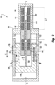
Fig. 2 is a schematic cross-sectional side elevation view of another embodiment of the assembly ofFig. 1 , wherein the cores and sets of coils are all on the same side of the piston; -
Figs. 3a-3c are a schematic cross-sectional axial elevation view, and two side elevation views of another embodiment of the assembly ofFig. 1 , showing a housing and core member configured to follow a curved stroke path; and -
Fig. 4 is a graph showing positional accuracy along the stroke of the assembly ofFig. 1 , including potential accuracy benefits in a subrange of the full stroke. - Reference will now be made to the drawings wherein like reference numerals identify similar structural features or aspects of the subject disclosure. For purposes of explanation and illustration, and not limitation, a partial view of an embodiment of an assembly in accordance with the disclosure is shown in
Fig. 1 and is designated generally byreference character 100. Other embodiments of systems in accordance with the disclosure, or aspects thereof, are provided inFigs. 2-4 , as will be described. The systems and methods described herein can be used to provide position sensing with both a large range of motion coverage as well as high accuracy relative to traditional configurations for Linear/Radial Variable Differential Transformers (LVDTs and RVDTs). - An
assembly 100 includes ahousing 102. A first set ofcoils 104 is mounted to thehousing 102. The first set ofcoils 104 extends in an axial direction along the axis A of thehousing 102 for a first length L1. A second set ofcoils 106 is mounted to thehousing 102. The second set ofcoils 106 extends in the axial direction along the axis A of thehousing 102 for a second length L2 that is shorter than the first length L1. Acore member 108 includes afirst core 110 and asecond core 112 in series with one another in the axial direction relative to axis A along thecore member 108. Thecore member 108 is moveable within thehousing 102 along a stroke S indicated schematically inFigs. 1-3 by the double pointed arrows. - For at least a first portion of the stroke, the
first core 110 is within the first set ofcoils 104. It is contemplated that thefirst core 110 can be within the first set ofcoils 104 for the entire stroke S, so that the LVDT comprised ofcore 110 and the set ofcoils 104 can provide position data for thecore member 108 for the entire stroke S. - For at least a second portion of the stroke S, the
second core 112 is within the second set ofcoils 106. The LVDT comprised of the second set ofcoils 106 andsecond core 112 is configured to provide greater spatial resolution for measurements of position of thecore member 108 than are the first set ofcoils 104 andfirst core 110. Thefirst core 110 is within the first set ofcoils 104 for a greater portion (L1) of the first stroke S than thesecond core 112 is within the second set of coils 106 (L2). The first portion of the stroke S where the first LVDT is operative and the second portion of the stroke S where the second LVDT is operative overlap in the axial direction of axis A. The second portion of the stroke S (where thesecond core 112 is within the second set of coils 106) is entirely within the length of first portion of the stroke S where thefirst core 110 is within the first set ofcoils 104. However, it is also contemplated that the first and second portions of the stroke S can be only partially overlapping or non-overlapping as needed for a given application. - The first set of
coils 104 is axially non-overlapping with the second set ofcoils 106. The first set ofcoils 104 is axially spaced apart from the second set ofcoils 106. The first set ofcoils 104 is coaxial about the axis A with the second set ofcoils 106. The first set ofcoils 104 overlaps with the second set ofcoils 106 in a radial direction R relative to the axial direction of axis A. The first set ofcoils 104 includes, in this axial order, a firstsecondary coil 114, aprimary coil 116, and a secondsecondary coil 118. The second set ofcoils 106 includes, in this axial order, a firstsecondary coil 120, aprimary coil 122, and a secondsecondary coil 124. - The
first core 110 is axially spaced apart along axis A from thesecond core 112. Thefirst core 110 is coaxial on axis A with thesecond core 112. Thefirst core 110 overlaps with thesecond core 110 in the radial direction R relative to the axial direction. Thefirst core 110 is longer than is thesecond core 112 in the axial direction of axis A, although this does not have to be the case. The core length can be up to the design of a variable differential transformer (VDT) to obtain optimal accuracy across the desired portion of a stroke. - With continued reference to
Fig. 1 , thehousing 102 is a valve housing defining aninlet 126 and anoutlet 128. Thecore member 108 includes avalve piston 130 having ametering passage 132 defined therein. Themetering passage 132 connects theinlet 126 in fluid communication with theoutlet 128, at least for a portion of the stroke S. Movement of thevalve piston 130 along the stroke S changes effective flow area through the metering passage to control flow from theinlet 126 to theoutlet 128, where the flow is indicated schematically inFigs. 1-3 by the curved flow arrows. InFig. 1 , thefirst core 110 is on one side of thevalve piston 132, i.e. the left side as oriented inFig. 1 . Thesecond core 112 is on a second side, i.e. the right side as oriented inFig. 1 , of thevalve piston 132 opposite the first side in the axial direction along the axis A. With reference toFig. 2 , like reference numerals indicate like components as described herein with reference toFig. 1 . InFig. 2 , thefirst core 110 and thesecond core 112 are both on the same side of thevalve piston 132, i.e. the right side as oriented inFig. 2 , in the axial direction of axis A. - While shown and described herein in the context of a valve, those skilled in the art will readily appreciate that systems and methods as disclosed herein can be used in actuators, or any other suitable device that uses position feedback. This can include devises that use linear position feedback and those that use position feedback rotationally.
- With reference now to
Fig. 3a , like reference numerals indicate like components as described above with respect toFig. 1 . Whereas inFigs. 1 and2 the stroke S is defined along a straight line for liner LVDT position sensing, inFig. 3 thehousing 102 and core member 108 (which in this case is a rotational linkage) and itspiston 132 are configured so the stroke S is defined along a curved path. This can allow for LVDT/RVDT position sensing along an arcuate path and/or angular position (rotational) sensing. As shown inFigs. 3b and 3c , which are side elevation views relative to the axial view ofFig. 3a , the coil sets 114/118 and 120/124 can all be on the same axial level as inFig. 3b , or multiple axial levels can be used for the different coil sets 114/118 versus 120/124 as inFig. 3c . - With reference now to
Fig. 4 , a graph is shown with normalized error on the vertical axis and position of the stoke S ofFigs. 1-3 along the horizontal axis. The points of the graph show that along the stroke S, the LVDT/RVDT allows for position sensing, but where there is a heighted accuracy (lower error) in the second portion P of stroke S where thesecond core 112 is within the second set ofcoils 106 as numbered inFigs. 1-3 . Designers can tune their designs to target the second portion P of the stroke S to be located in a portion of their design where it is beneficial to target higher accuracy. For example, the more sensitive portion of a valve stroke could be positioned in a design to coincide with the second portion P of the stroke S. This allows for measurements along the entire stroke S, but with the added benefit of extra accuracy in the more important portion P of the stroke S. - Systems and methods as disclosed herein can provide potential advantages including the following potential advantages. There can be a relaxation of limits on design tolerances is areas of high accuracy due to the targeted accuracy of the second portion P of the stroke S. This may also be utilized to obtain multiple points of increased accuracy across the full range of operation, e.g. multiple second sets of
coils 106 and the correspondingcores 112 in asingle assembly 100. There is a potential to reduce error due to thermal growth by limiting the length of certain elements in the LVDT/RVDT. There is also a potential for additional error checking, e.g. on an engine with position cross-reference between the two or more LVDT/RVDT outputs. - The methods and systems of the present disclosure, as described above and shown in the drawings, provide for position sensing with both large operating range and high accuracy relative to traditional configurations. While the apparatus and methods of the subject disclosure have been shown and described with reference to preferred embodiments, those skilled in the art will readily appreciate that changes and/or modifications may be made thereto without departing from the scope of the invention as defined by the claims.
Claims (15)
- An assembly comprising:a housing (102);a first set of coils (104) mounted to the housing, wherein the first set of coils extends in a first direction along the housing for a first length;a second set of coils (106) mounted to the housing, wherein the second set of coils extends in the first direction along the housing for a second length that is shorter than the first length; anda core member (108) including a first core and a second core in series with one another in the first direction along the core member, wherein the core member is moveable within the housing along a stroke, wherein for at least a first portion of the stroke, the first core is within the first set of coils, and wherein for at least a second portion of the stroke, the second core is within the second set of coils.
- The assembly as recited in claim 1, wherein the first set of coils is non-overlapping with the second set of coils in the first direction, and optionally wherein the first set of coils is spaced apart from the second set of coils in the first direction.
- The assembly as recited in claim 1, wherein the first set of coils is coaxial with the second set of coils, and optionally wherein the first set of coils overlaps with the second set of coils in a radial direction relative to the first direction.
- The assembly as recited in claim 1. 2 or 3, wherein the first set of coils includes, in this axial order, a first secondary coil (114), a primary coil (116), and a second secondary coil (118).
- The assembly as recited in any preceding claim, wherein the second set of coils includes, in this axial order, a first secondary coil (120), a primary coil (122), and a second secondary coil (124).
- The assembly as recited in any preceding claim, wherein the first core is axially spaced apart from the second core.
- The assembly as recited in any preceding claim, wherein the first core is coaxial with the second core, and optionally wherein the first core overlaps with the second core in a radial direction relative to the first direction, wherein the first direction is axial.
- The assembly as recited in any preceding claim, wherein the housing is a valve housing defining an inlet and an outlet.
- The assembly as recited in claim 8, wherein the core member includes a valve piston (132) having a metering passage defined therein, wherein the metering passage connects the inlet in fluid communication with the outlet, and wherein movement of the valve piston along the stroke changes effective flow area through the metering passage to control flow from the inlet to the outlet.
- The assembly as recited in claim 9, wherein the first core is on one side of the valve piston, and wherein the second core is on a second side of the valve piston opposite the first side in the axial direction, or wherein the first core is on one side of the valve piston, and wherein the second core is also on the first side of the valve piston in the axial direction.
- The assembly as recited in any preceding claim, wherein the housing and piston are configured so the stroke is defined along a straight path, or wherein the housing and piston are configured so the stroke is defined along a curved path.
- The assembly as recited in any preceding claim, wherein the second set of coils and second core are configured to provide greater spatial resolution for measurements of position of the core member than are the first set of coils and first core.
- The assembly as recited in claim 12, wherein the first core is within the first set of coils for a greater portion of the first stroke than the second core is within the second set of coils.
- The assembly as recited in any preceding claim, wherein the first portion of the stroke and the second portion of the stroke overlap in the axial direction.
- The assembly as recited in claim 14, wherein the second portion of the stroke is entirely within the first portion of the stroke.
Applications Claiming Priority (1)
| Application Number | Priority Date | Filing Date | Title |
|---|---|---|---|
| US17/554,951 US12018768B2 (en) | 2021-12-17 | 2021-12-17 | Dual range position sensing configurations for variable differential transformers |
Publications (2)
| Publication Number | Publication Date |
|---|---|
| EP4198355A1 true EP4198355A1 (en) | 2023-06-21 |
| EP4198355B1 EP4198355B1 (en) | 2025-08-13 |
Family
ID=84389116
Family Applications (1)
| Application Number | Title | Priority Date | Filing Date |
|---|---|---|---|
| EP22211497.7A Active EP4198355B1 (en) | 2021-12-17 | 2022-12-05 | Dual range position sensing configurations for variable differential transformers |
Country Status (2)
| Country | Link |
|---|---|
| US (1) | US12018768B2 (en) |
| EP (1) | EP4198355B1 (en) |
Citations (6)
| Publication number | Priority date | Publication date | Assignee | Title |
|---|---|---|---|---|
| US3488578A (en) * | 1967-02-20 | 1970-01-06 | Kockums Mekaniska Verkstads Ab | Electromagnetic transmitters for positional indication |
| JPS6049404U (en) * | 1983-09-12 | 1985-04-06 | 株式会社ミツトヨ | Displacement measuring device |
| US20100090144A1 (en) * | 2008-10-14 | 2010-04-15 | Brandt Jr Robert O | High-speed actuator for valves |
| US20120326824A1 (en) * | 2011-06-24 | 2012-12-27 | Ian Harris | Inductive sensor with datum adjustment |
| WO2014012608A1 (en) * | 2012-07-19 | 2014-01-23 | Hydac System Gmbh | Valve, in particular continuously adjustable valve |
| US20200003331A1 (en) * | 2018-06-29 | 2020-01-02 | Robert Bosch Gmbh | Displacement Transducer |
Family Cites Families (14)
| Publication number | Priority date | Publication date | Assignee | Title |
|---|---|---|---|---|
| US3173003A (en) * | 1960-04-29 | 1965-03-09 | Taylor Instrument Co | Fluid flow measuring and computing apparatus |
| US4567813A (en) * | 1982-05-06 | 1986-02-04 | Moog Inc. | Pressure equalization of multiple valves |
| JPH0349404U (en) | 1989-09-22 | 1991-05-14 | ||
| GB2260821B (en) | 1991-10-25 | 1995-01-04 | United Technologies Corp | Pitch change system |
| JPH0626884A (en) | 1992-07-07 | 1994-02-04 | San Tesuto Kk | Position detection device |
| US7066189B2 (en) * | 2002-12-20 | 2006-06-27 | Control Components, Inc. | Predictive maintenance and initialization system for a digital servovalve |
| WO2009005426A1 (en) * | 2007-07-02 | 2009-01-08 | Parker Hannifin Ab | Fluid valve arrangement |
| US8264315B2 (en) | 2010-08-03 | 2012-09-11 | Honeywell International Inc. | Linear variable differential transformers |
| US9863787B2 (en) | 2014-07-31 | 2018-01-09 | Parker-Hannifin Corporation | Linear variable differential transformer with multi-range secondary windings for high precision |
| JP2016142646A (en) | 2015-02-03 | 2016-08-08 | 多摩川精機株式会社 | Double type differential transformer structure |
| EP3176443B1 (en) * | 2015-12-01 | 2020-05-06 | Claverham Limited | Hydraulic valve |
| US10641597B2 (en) | 2018-02-22 | 2020-05-05 | Bell Helicopter Textron Inc. | Method and apparatus for a precision position sensor |
| US11293744B2 (en) | 2019-03-01 | 2022-04-05 | Renesas Electronics America Inc. | Method for increasing the position measurement accuracy using inductive position sensor |
| CN115989379A (en) * | 2020-02-14 | 2023-04-18 | 海德福斯股份有限公司 | Hydraulic cartridge valve and method with position monitoring mechanism and hydraulic control system |
-
2021
- 2021-12-17 US US17/554,951 patent/US12018768B2/en active Active
-
2022
- 2022-12-05 EP EP22211497.7A patent/EP4198355B1/en active Active
Patent Citations (6)
| Publication number | Priority date | Publication date | Assignee | Title |
|---|---|---|---|---|
| US3488578A (en) * | 1967-02-20 | 1970-01-06 | Kockums Mekaniska Verkstads Ab | Electromagnetic transmitters for positional indication |
| JPS6049404U (en) * | 1983-09-12 | 1985-04-06 | 株式会社ミツトヨ | Displacement measuring device |
| US20100090144A1 (en) * | 2008-10-14 | 2010-04-15 | Brandt Jr Robert O | High-speed actuator for valves |
| US20120326824A1 (en) * | 2011-06-24 | 2012-12-27 | Ian Harris | Inductive sensor with datum adjustment |
| WO2014012608A1 (en) * | 2012-07-19 | 2014-01-23 | Hydac System Gmbh | Valve, in particular continuously adjustable valve |
| US20200003331A1 (en) * | 2018-06-29 | 2020-01-02 | Robert Bosch Gmbh | Displacement Transducer |
Also Published As
| Publication number | Publication date |
|---|---|
| US20230194014A1 (en) | 2023-06-22 |
| US12018768B2 (en) | 2024-06-25 |
| EP4198355B1 (en) | 2025-08-13 |
Similar Documents
| Publication | Publication Date | Title |
|---|---|---|
| RU2473869C2 (en) | Device to measure piston position in cylinder, assembly comprising said cylinder, piston and such device, and aircraft engine incorporating this assembly | |
| US20100127695A1 (en) | Inductive sensors | |
| CN103375269B (en) | Metering valve | |
| US8264315B2 (en) | Linear variable differential transformers | |
| US11009148B2 (en) | Displacement transducer | |
| EP4198355B1 (en) | Dual range position sensing configurations for variable differential transformers | |
| US20110043308A1 (en) | Integrated sensor for position contol | |
| CN102400971B (en) | Electric hydaulic linear servo valve | |
| JP2013007745A (en) | Induction sensor with datum adjustment | |
| US7019514B2 (en) | Rotary to linear LVDT system | |
| CA3034492A1 (en) | Adjustable stops for actuator piston | |
| US12510178B2 (en) | Proportional actuator and unibody magnetic housing | |
| US5432493A (en) | Two linear differential transformers with armature | |
| EP1567825B1 (en) | Device for measuring the lift of poppet valves | |
| US20170345537A1 (en) | Electromagnetic actuator | |
| EP3531077B1 (en) | Vdt with high permeability shield | |
| US11915867B2 (en) | LVDT with integrated anti-rotation | |
| EP4400751A1 (en) | Proximity probe piston positioning systems | |
| US11384855B2 (en) | Fluid pressure valve | |
| EP2333460B1 (en) | Poppet valve with dual flow area gain | |
| US12098647B2 (en) | Position sensor for variable vane assembly and method for calibrating same | |
| KR20250142397A (en) | Systems and assemblies involving flexible printed circuit boards having coils printed thereon to indicate the location of movable elements. | |
| CN115111373B (en) | A cage-type giant magnetostrictive proportional valve for electric propulsion | |
| EP4169045A1 (en) | Electromagnetic actuator with position detection | |
| WO2016182536A1 (en) | Three-way valve |
Legal Events
| Date | Code | Title | Description |
|---|---|---|---|
| PUAI | Public reference made under article 153(3) epc to a published international application that has entered the european phase |
Free format text: ORIGINAL CODE: 0009012 |
|
| STAA | Information on the status of an ep patent application or granted ep patent |
Free format text: STATUS: THE APPLICATION HAS BEEN PUBLISHED |
|
| AK | Designated contracting states |
Kind code of ref document: A1 Designated state(s): AL AT BE BG CH CY CZ DE DK EE ES FI FR GB GR HR HU IE IS IT LI LT LU LV MC ME MK MT NL NO PL PT RO RS SE SI SK SM TR |
|
| STAA | Information on the status of an ep patent application or granted ep patent |
Free format text: STATUS: REQUEST FOR EXAMINATION WAS MADE |
|
| 17P | Request for examination filed |
Effective date: 20231221 |
|
| RBV | Designated contracting states (corrected) |
Designated state(s): AL AT BE BG CH CY CZ DE DK EE ES FI FR GB GR HR HU IE IS IT LI LT LU LV MC ME MK MT NL NO PL PT RO RS SE SI SK SM TR |
|
| GRAP | Despatch of communication of intention to grant a patent |
Free format text: ORIGINAL CODE: EPIDOSNIGR1 |
|
| STAA | Information on the status of an ep patent application or granted ep patent |
Free format text: STATUS: GRANT OF PATENT IS INTENDED |
|
| INTG | Intention to grant announced |
Effective date: 20250311 |
|
| GRAS | Grant fee paid |
Free format text: ORIGINAL CODE: EPIDOSNIGR3 |
|
| GRAA | (expected) grant |
Free format text: ORIGINAL CODE: 0009210 |
|
| STAA | Information on the status of an ep patent application or granted ep patent |
Free format text: STATUS: THE PATENT HAS BEEN GRANTED |
|
| AK | Designated contracting states |
Kind code of ref document: B1 Designated state(s): AL AT BE BG CH CY CZ DE DK EE ES FI FR GB GR HR HU IE IS IT LI LT LU LV MC ME MK MT NL NO PL PT RO RS SE SI SK SM TR |
|
| REG | Reference to a national code |
Ref country code: GB Ref legal event code: FG4D |
|
| REG | Reference to a national code |
Ref country code: CH Ref legal event code: EP |
|
| REG | Reference to a national code |
Ref country code: DE Ref legal event code: R096 Ref document number: 602022019338 Country of ref document: DE |
|
| REG | Reference to a national code |
Ref country code: IE Ref legal event code: FG4D |
|
| REG | Reference to a national code |
Ref country code: NL Ref legal event code: MP Effective date: 20250813 |
|
| PG25 | Lapsed in a contracting state [announced via postgrant information from national office to epo] |
Ref country code: IS Free format text: LAPSE BECAUSE OF FAILURE TO SUBMIT A TRANSLATION OF THE DESCRIPTION OR TO PAY THE FEE WITHIN THE PRESCRIBED TIME-LIMIT Effective date: 20251213 |
|
| PG25 | Lapsed in a contracting state [announced via postgrant information from national office to epo] |
Ref country code: NO Free format text: LAPSE BECAUSE OF FAILURE TO SUBMIT A TRANSLATION OF THE DESCRIPTION OR TO PAY THE FEE WITHIN THE PRESCRIBED TIME-LIMIT Effective date: 20251113 |
|
| REG | Reference to a national code |
Ref country code: LT Ref legal event code: MG9D |
|
| PG25 | Lapsed in a contracting state [announced via postgrant information from national office to epo] |
Ref country code: PT Free format text: LAPSE BECAUSE OF FAILURE TO SUBMIT A TRANSLATION OF THE DESCRIPTION OR TO PAY THE FEE WITHIN THE PRESCRIBED TIME-LIMIT Effective date: 20251215 |
|
| PG25 | Lapsed in a contracting state [announced via postgrant information from national office to epo] |
Ref country code: FI Free format text: LAPSE BECAUSE OF FAILURE TO SUBMIT A TRANSLATION OF THE DESCRIPTION OR TO PAY THE FEE WITHIN THE PRESCRIBED TIME-LIMIT Effective date: 20250813 |
|
| PG25 | Lapsed in a contracting state [announced via postgrant information from national office to epo] |
Ref country code: HR Free format text: LAPSE BECAUSE OF FAILURE TO SUBMIT A TRANSLATION OF THE DESCRIPTION OR TO PAY THE FEE WITHIN THE PRESCRIBED TIME-LIMIT Effective date: 20250813 Ref country code: NL Free format text: LAPSE BECAUSE OF FAILURE TO SUBMIT A TRANSLATION OF THE DESCRIPTION OR TO PAY THE FEE WITHIN THE PRESCRIBED TIME-LIMIT Effective date: 20250813 |
|
| PG25 | Lapsed in a contracting state [announced via postgrant information from national office to epo] |
Ref country code: GR Free format text: LAPSE BECAUSE OF FAILURE TO SUBMIT A TRANSLATION OF THE DESCRIPTION OR TO PAY THE FEE WITHIN THE PRESCRIBED TIME-LIMIT Effective date: 20251114 |
|
| PG25 | Lapsed in a contracting state [announced via postgrant information from national office to epo] |
Ref country code: SE Free format text: LAPSE BECAUSE OF FAILURE TO SUBMIT A TRANSLATION OF THE DESCRIPTION OR TO PAY THE FEE WITHIN THE PRESCRIBED TIME-LIMIT Effective date: 20250813 |
|
| PG25 | Lapsed in a contracting state [announced via postgrant information from national office to epo] |
Ref country code: LV Free format text: LAPSE BECAUSE OF FAILURE TO SUBMIT A TRANSLATION OF THE DESCRIPTION OR TO PAY THE FEE WITHIN THE PRESCRIBED TIME-LIMIT Effective date: 20250813 |
|
| PG25 | Lapsed in a contracting state [announced via postgrant information from national office to epo] |
Ref country code: PL Free format text: LAPSE BECAUSE OF FAILURE TO SUBMIT A TRANSLATION OF THE DESCRIPTION OR TO PAY THE FEE WITHIN THE PRESCRIBED TIME-LIMIT Effective date: 20250813 Ref country code: BG Free format text: LAPSE BECAUSE OF FAILURE TO SUBMIT A TRANSLATION OF THE DESCRIPTION OR TO PAY THE FEE WITHIN THE PRESCRIBED TIME-LIMIT Effective date: 20250813 |
|
| PG25 | Lapsed in a contracting state [announced via postgrant information from national office to epo] |
Ref country code: RS Free format text: LAPSE BECAUSE OF FAILURE TO SUBMIT A TRANSLATION OF THE DESCRIPTION OR TO PAY THE FEE WITHIN THE PRESCRIBED TIME-LIMIT Effective date: 20251113 |
|
| PG25 | Lapsed in a contracting state [announced via postgrant information from national office to epo] |
Ref country code: ES Free format text: LAPSE BECAUSE OF FAILURE TO SUBMIT A TRANSLATION OF THE DESCRIPTION OR TO PAY THE FEE WITHIN THE PRESCRIBED TIME-LIMIT Effective date: 20250813 |
|
| REG | Reference to a national code |
Ref country code: AT Ref legal event code: MK05 Ref document number: 1824955 Country of ref document: AT Kind code of ref document: T Effective date: 20250813 |
|
| PG25 | Lapsed in a contracting state [announced via postgrant information from national office to epo] |
Ref country code: RO Free format text: LAPSE BECAUSE OF FAILURE TO SUBMIT A TRANSLATION OF THE DESCRIPTION OR TO PAY THE FEE WITHIN THE PRESCRIBED TIME-LIMIT Effective date: 20250813 |
|
| PG25 | Lapsed in a contracting state [announced via postgrant information from national office to epo] |
Ref country code: SM Free format text: LAPSE BECAUSE OF FAILURE TO SUBMIT A TRANSLATION OF THE DESCRIPTION OR TO PAY THE FEE WITHIN THE PRESCRIBED TIME-LIMIT Effective date: 20250813 |
|
| PG25 | Lapsed in a contracting state [announced via postgrant information from national office to epo] |
Ref country code: DK Free format text: LAPSE BECAUSE OF FAILURE TO SUBMIT A TRANSLATION OF THE DESCRIPTION OR TO PAY THE FEE WITHIN THE PRESCRIBED TIME-LIMIT Effective date: 20250813 |
|
| PG25 | Lapsed in a contracting state [announced via postgrant information from national office to epo] |
Ref country code: AT Free format text: LAPSE BECAUSE OF FAILURE TO SUBMIT A TRANSLATION OF THE DESCRIPTION OR TO PAY THE FEE WITHIN THE PRESCRIBED TIME-LIMIT Effective date: 20250813 |
|
| PG25 | Lapsed in a contracting state [announced via postgrant information from national office to epo] |
Ref country code: IT Free format text: LAPSE BECAUSE OF FAILURE TO SUBMIT A TRANSLATION OF THE DESCRIPTION OR TO PAY THE FEE WITHIN THE PRESCRIBED TIME-LIMIT Effective date: 20250813 |
|
| PG25 | Lapsed in a contracting state [announced via postgrant information from national office to epo] |
Ref country code: CZ Free format text: LAPSE BECAUSE OF FAILURE TO SUBMIT A TRANSLATION OF THE DESCRIPTION OR TO PAY THE FEE WITHIN THE PRESCRIBED TIME-LIMIT Effective date: 20250813 |
|
| PG25 | Lapsed in a contracting state [announced via postgrant information from national office to epo] |
Ref country code: EE Free format text: LAPSE BECAUSE OF FAILURE TO SUBMIT A TRANSLATION OF THE DESCRIPTION OR TO PAY THE FEE WITHIN THE PRESCRIBED TIME-LIMIT Effective date: 20250813 Ref country code: SK Free format text: LAPSE BECAUSE OF FAILURE TO SUBMIT A TRANSLATION OF THE DESCRIPTION OR TO PAY THE FEE WITHIN THE PRESCRIBED TIME-LIMIT Effective date: 20250813 |