EP4198227B1 - Inertial safety system for a vehicle door handle - Google Patents
Inertial safety system for a vehicle door handle Download PDFInfo
- Publication number
- EP4198227B1 EP4198227B1 EP21214906.6A EP21214906A EP4198227B1 EP 4198227 B1 EP4198227 B1 EP 4198227B1 EP 21214906 A EP21214906 A EP 21214906A EP 4198227 B1 EP4198227 B1 EP 4198227B1
- Authority
- EP
- European Patent Office
- Prior art keywords
- inertial
- locking
- locking device
- rotation axis
- mass
- Prior art date
- Legal status (The legal status is an assumption and is not a legal conclusion. Google has not performed a legal analysis and makes no representation as to the accuracy of the status listed.)
- Active
Links
Images




Classifications
-
- E—FIXED CONSTRUCTIONS
- E05—LOCKS; KEYS; WINDOW OR DOOR FITTINGS; SAFES
- E05B—LOCKS; ACCESSORIES THEREFOR; HANDCUFFS
- E05B77/00—Vehicle locks characterised by special functions or purposes
- E05B77/02—Vehicle locks characterised by special functions or purposes for accident situations
- E05B77/04—Preventing unwanted lock actuation, e.g. unlatching, at the moment of collision
- E05B77/06—Preventing unwanted lock actuation, e.g. unlatching, at the moment of collision by means of inertial forces
-
- E—FIXED CONSTRUCTIONS
- E05—LOCKS; KEYS; WINDOW OR DOOR FITTINGS; SAFES
- E05B—LOCKS; ACCESSORIES THEREFOR; HANDCUFFS
- E05B85/00—Details of vehicle locks not provided for in groups E05B77/00 - E05B83/00
- E05B85/10—Handles
- E05B85/14—Handles pivoted about an axis parallel to the wing
-
- E—FIXED CONSTRUCTIONS
- E05—LOCKS; KEYS; WINDOW OR DOOR FITTINGS; SAFES
- E05B—LOCKS; ACCESSORIES THEREFOR; HANDCUFFS
- E05B77/00—Vehicle locks characterised by special functions or purposes
- E05B77/42—Means for damping the movement of lock parts, e.g. slowing down the return movement of a handle
Definitions
- the invention relates to a safety device for a vehicle door handle, in particular to avoid unsolicited opening of said door during a side crash scenario.
- the inertia of the handle pieces can lead to an actuation of the door latch.
- a major risk in that case is the opening of the door, which may lead to the occupants being injured by being exposed to the outside environment or even thrown out of the vehicle.
- Reversible inertial systems generally include a mass that is linked to the locking component in such a way that it triggers the locking of the door when it moves when subjected to an acceleration above a predetermined threshold. Said mass is configured to come back to its rest position once the acceleration has decreased.
- a mass that is linked to the locking component in such a way that it triggers the locking of the door when it moves when subjected to an acceleration above a predetermined threshold.
- Said mass is configured to come back to its rest position once the acceleration has decreased.
- Such a system is for example known from document WO2004042177 .
- a reversible inertial system is that after a crash, the handle (unless it has been destroyed during the crash) is again free to operate such that pulling on the handle will allow to open the door. This can be helpful to rescue the passengers.
- Another advantage of such a system is its high reactivity : being reversible, its sensitivity to variations in acceleration can be set as high as there is no risk to block the handle use permanently during a normal use.
- Irreversible systems include components which simply permanently block the handle lever rotation and prevent door opening when subject to an acceleration above a predetermined threshold.
- Such a system is for example known from document WO2006003197 .
- inertial systems comprising two masses driven by inertia under opposite acceleration forces have been considered.
- Such a system is known EP 2 818 614 .
- the spatial configuration and kinematics of the inertial system shown in this document in particular owing to the shape of its components and their movement scheme, make it voluminous.
- the purpose of the invention is therefore to provide an inertial system that has high reactivity, prevents rebounds and the behaviour of which is predictable, all the while allowing door opening even after a crash, that is compact.
- the invention is directed to an inertial system for a vehicle door handle assembly comprising :
- the inertial system may act like a reversible inertial system with high sensitivity, all the while having a predictable behaviour in case of rebounds.
- the initial acceleration due to the impact will trigger the movement of one or both masses, thus blocking the actuation of the door handle assembly.
- a rebound even if a subsequent acceleration occurs along an opposite direction, it will not cause the unlocking of the door as it will trigger the movement of the second mass, thus maintaining the blocking of the actuation of the door handle assembly.
- the locking device for example comprises a locking end and at least a driven end, the locking device being movable between a locking position in which the locking end comes into contact with the door handle, for example via a blocking device, to prevent actuation of the door handle and a rest position into which the locking end is not in contact with the door handle, for example via a blocking device, the movement between the rest and locking position and vice versa being driven by a force applied by a driving end that is linked to the first and/or second inertial mass onto the driven end.
- the movement according to which the locking device moves between the rest and the locking position is for example a pivoting movement.
- the inertial system for example comprises a primary rotation axis and a first pivoting part pivoting about said primary rotation axis, the first inertial mass being supported by said first pivoting part.
- the locking device is for example supported by the primary rotation axis and its rotational movement is a pivoting movement about the primary rotation axis.
- the first pivoting part for example comprises a first body linking a fixed end mounted on the primary rotation axis to a first mass end supporting the first inertial mass.
- the inertial system preferably comprises a secondary rotation axis and a second pivoting part pivoting about said secondary rotation axis, the second inertial mass being supported by said second pivoting part.
- the inertial system also comprises first elastic means, said first elastic means being in a minimal tensile stress state when the locking device is in rest position, and configured to apply a force or torque on the locking device, to bring said locking device from the locking position back in rest position.
- the third elastic means can be removed to simplify the embodiment and the first inertial mass can be reverted to rest position by the action of the locking device.
- the vehicle door handle assembly 10 comprises a door handle 12, which here is known from the prior art, and usually comprises a bracket (not shown for the sake of comprehension) onto which is affixed an inertial system 14.
- Locking device comprises a locking body 18 that is mounted pivotably on a primary rotation axis 20.
- primary rotation axis 20 extends along axis Z.
- locking body 18 is substantially cylindrical in shape and is hollowed out (i.e. locking body 18 is annular) to accommodate primary rotation axis 20. Hence, locking body 18 extends along primary rotation axis 20. In that way, locking device 16 may pivot about primary rotation axis 20.
- locking device 16 comprises a locking end 16L, a first driven end 16D and a second driven end 17D.
- locking end 16L and both driven ends 16D, 17D project from locking body 18 substantially perpendicularly to primary rotation axis 20.
- driven ends 16D, 17D project from locking body 18 on the same side of the primary rotation axis 20, while locking end 16L is placed on the opposite side of primary rotation axis 18.
- locking body 18 locking end 16L and driven end 16D are made of one piece.
- locking end 16L is located between driven ends 16D, 17D along primary rotation axis 20.
- Locking end 16L extends along an axis that is parallel to primary rotation axis 20. Locking end 16L here has a trapezoidal section, but other sections could be envisioned. At any rate, preferably locking end 16L comprises a planar surface that comes into contact with a blocking device 22 that prevents opening of the handle door 12 as will now be explained.
- Both driven end 16D, 17D also extend along an axis that is parallel to primary rotation axis 20 and extends in such a way that is longer than the whole length of locking body 18.
- Both driven ends 16L here have a trapezoidal section, but other sections could be envisioned.
- both driven ends 16D, 17D also comprises a planar surface for a purpose that will become apparent later on.
- first driven end 16D is slightly longer than second driven end 17D along primary rotation axis 20.
- Locking device 16 is movable between a locking position in which the locking end 16L comes into contact with the door handle 12, here with a blocking device 22 to prevent actuation of the door handle 12, and a rest position in which the locking end 16L is not in contact with the door handle 12 via the blocking device 22.
- the movement according to which the locking device 16 moves between the rest and the locking position is a pivoting movement.
- said pivoting movement is about primary rotary axis 20.
- Inertial system 14 also comprises a first pivoting part 24 pivoting about primary rotation axis 20. First pivoting part 24 is located facing first driven end 16D.
- first pivoting part 24 comprises a first body 28 linking a fixed end 24E mounted on the primary rotation axis 20 to a first mass end 24M supporting a first inertial mass 26.
- first pivoting part 24 is lever-shaped.
- fixed end 24E is substantially cylindrical and is hollowed-out (i.e. fixed end 24E is annular) to accommodate first pivoting axis 20, much like locking body 18.
- fixed end 24E extends along primary rotation axis 20.
- fixed end 24E extends along a smaller portion of the length of primary rotation axis 20.
- First inertial mass 26 may be provided with a socket in which a bumper 27 can be inserted.
- bumper 27 may be made of rubber or any comparable material and injected in the socket. Bumper 27 reduces the noise impact of inertial masses 26 when it moves about and hits its position stop. This movement will be explained later on.
- First pivoting part 24 also comprises a first driving end 24D, visible on Figure 3 , which here projects from first inertial mass 26 towards driven end 16D so as to face it. Considering the configuration shown on Figures 2 and 3 , first driving end 24D extends perpendicularly to primary rotation axis 20.
- Driven end 16D of the locking device may be contact, here via its planar surface, with first driving end 24, and is also driven by first body 28 as will be explained now.
- first inertial mass 26 is configured such that, when subjected to an inertial force (noted F1 on Figure 6 ) acting in a first acceleration direction, is configured to move along a first movement direction from a rest position, shown on Figures 2 , 3 and 4 , allowing the opening of the door by actuation of the door handle 12, to a locking position, shown on Figures 5 and 6 , activating the locking device 16.
- F1 inertial force
- the first acceleration direction is the opposite direction of axis Y
- the initial first movement direction is also the direction of axis Y, the overall movement of first inertial mass 26 being a rotational movement about first pivoting axis 20. Said rotational movement is in a counter clockwise direction in the example shown on the Figures.
- Inertial system 14 also comprises a secondary rotation axis 30 and a second pivoting part 32 pivoting about said secondary rotation axis 30. Second pivoting part 32 is located facing first driven end 16D.
- Secondary rotation axis 30 here is parallel to first rotation axis 20.
- Second pivoting part 32 comprises a second body 33 linking a driving end 32D and a second inertial mass 34.
- Second body 33 is hollowed-out to accommodate mounted on the secondary rotation axis 30 such.
- the second driving end 32D and the second mass end are thus located from either side of the secondary rotation axis 30.
- Second driven end 17D of the locking device may be in contact with and driven by the driving end 32D of second pivoting part 32.
- Second inertial mass 34 may also be provided with a bumper much like first inertial mass 26.
- second inertial mass 34 When subjected to an acceleration force (noted F2 on Figure 8 ) acting in a second acceleration direction opposite the first acceleration direction, second inertial mass 34 is configured to move along a second movement direction, from a rest position, shown on Figures 3 and 4 , allowing the opening of the door by actuation of the door handle 12 to a locking position activating the locking device 18.
- first inertial mass 26 pivots about primary rotation axis 20 along a first movement direction, driving locking device 16 such that it comes into contact with blocking device 22.
- first elastic means 36 make locking device 16 come back to its rest position shown on Figures 2 to 4 .
- dampening means 40 are provided such that locking device 16 comes back to its rest position only after a predetermined period of time, which for example corresponds to a nominal crash time, to ensure the locking of the door lasts long enough. By going back to its rest position, locking device 16 also drives first inertial 26 back into its rest position.
- the masses 26, 34 move from their rest position to their locking position along two different directions allows for a more compact configuration of the masses 26, 34, as they can notably be located on the same side of primary rotation axis 20 and be lodged inside a small housing 15.
Landscapes
- Lock And Its Accessories (AREA)
Description
- The invention relates to a safety device for a vehicle door handle, in particular to avoid unsolicited opening of said door during a side crash scenario.
- When a vehicle undergoes a lateral collision, the inertia of the handle pieces can lead to an actuation of the door latch. A major risk in that case is the opening of the door, which may lead to the occupants being injured by being exposed to the outside environment or even thrown out of the vehicle.
- To avoid that risk, almost all current vehicle handles integrate components dedicated to block the kinematics of the handle, and thus prevent door opening upon impact. These blocking or locking components are triggered by being subjected to an acceleration above a predetermined threshold (usually several tens of g) and are thus usually called "inertial systems" or "inertial lockers".
- Current inertial systems are usually divided into two categories : reversible and irreversible.
- Reversible inertial systems generally include a mass that is linked to the locking component in such a way that it triggers the locking of the door when it moves when subjected to an acceleration above a predetermined threshold. Said mass is configured to come back to its rest position once the acceleration has decreased. Such a system is for example known from document
WO2004042177 . - The main advantage of a reversible inertial system is that after a crash, the handle (unless it has been destroyed during the crash) is again free to operate such that pulling on the handle will allow to open the door. This can be helpful to rescue the passengers. Another advantage of such a system is its high reactivity : being reversible, its sensitivity to variations in acceleration can be set as high as there is no risk to block the handle use permanently during a normal use.
- On the other hand, this sensitivity turns into a disadvantage as rebounds, i.e. alternate accelerations forces, may occur during the crash and trigger, though rarely, a brief unlocking of the door handle as the mass may return briefly to its original rest position. Moreover, the behaviour of a reversible inertial system is difficult to anticipate in real conditions. To avoid this, damping systems can be introduced in the inertial system kinematics to dampen the return to the rest position. Such a system is for example known from document
WO 2008/068262 . - Irreversible systems, in turn, include components which simply permanently block the handle lever rotation and prevent door opening when subject to an acceleration above a predetermined threshold. Such a system is for example known from document
WO2006003197 . - The main advantage of an irreversible inertial system is that once triggered, no rebounds can occur as it is definitively locked. On the other hand, its sensitivity has to remain low as it must not be triggered during situations that may involve high accelerations but remain in the domain of a normal use of the vehicle (door slamming, vibrations, etc.), which may cause a delay in activation during a crash. Another disadvantage lies in the fact that the door cannot be opened after the crash due to definitive locking. This may be considered acceptable from a regulations point of view, but not for some original equipment manufacturers (OEM).
- It has thus been sought to provide a reversible inertial system that is less affected by rebounds, i.e. has less chances of briefly unlock the door handle when subjected by alternate acceleration forces.
- To that end, inertial systems comprising two masses driven by inertia under opposite acceleration forces have been considered. Such a system is known
EP 2 818 614 . However, the spatial configuration and kinematics of the inertial system shown in this document, in particular owing to the shape of its components and their movement scheme, make it voluminous. - The purpose of the invention is therefore to provide an inertial system that has high reactivity, prevents rebounds and the behaviour of which is predictable, all the while allowing door opening even after a crash, that is compact.
- To that end, the invention is directed to an inertial system for a vehicle door handle assembly comprising :
- a locking device configured to prevent the actuation of the door handle assembly upon activation,
- a first inertial mass, which, when subjected to an acceleration force acting in a first acceleration direction, is configured to move along a first movement direction from a rest position allowing the opening of the door by actuation of the door handle, to a locking position activating the locking device,
- Thanks to the presence of not one, but two inertial masses, and the fact that they move from a rest position to the blocking position according to two opposite directions, the inertial system may act like a reversible inertial system with high sensitivity, all the while having a predictable behaviour in case of rebounds. In the case of a crash, the initial acceleration due to the impact will trigger the movement of one or both masses, thus blocking the actuation of the door handle assembly. Then, in the case of a rebound, even if a subsequent acceleration occurs along an opposite direction, it will not cause the unlocking of the door as it will trigger the movement of the second mass, thus maintaining the blocking of the actuation of the door handle assembly.
- In addition, owing to the fact that the masses move from their rest position to their locking position along two different directions allows for a more compact configuration of the masses, as they can be located on the same side of a pivoting axis for example.
- In order to further ensure the compacity of the inertial system, the locking device for example comprises a locking end and at least a driven end, the locking device being movable between a locking position in which the locking end comes into contact with the door handle, for example via a blocking device, to prevent actuation of the door handle and a rest position into which the locking end is not in contact with the door handle, for example via a blocking device, the movement between the rest and locking position and vice versa being driven by a force applied by a driving end that is linked to the first and/or second inertial mass onto the driven end.
- For simplicity purposes, the movement according to which the locking device moves between the rest and the locking position is for example a pivoting movement.
- For simplicity purposes, the inertial system for example comprises a primary rotation axis and a first pivoting part pivoting about said primary rotation axis, the first inertial mass being supported by said first pivoting part.
- In order to further ensure the compacity of the inertial system, the locking device is for example supported by the primary rotation axis and its rotational movement is a pivoting movement about the primary rotation axis.
- According to a preferred embodiment, the first pivoting part for example comprises a first body linking a fixed end mounted on the primary rotation axis to a first mass end supporting the first inertial mass.
- In order to further ensure the compacity of the inertial system, the driven end is for example in contact and driven by the first body.
- According to a preferred embodiment the inertial system preferably comprises a secondary rotation axis and a second pivoting part pivoting about said secondary rotation axis, the second inertial mass being supported by said second pivoting part.
- In order to further ensure the compacity of the inertial system, the second pivoting part for example comprises a driving end and a second mass end, the driving end and the second mass end being located from either side of the secondary rotation axis.
- According to a preferred embodiment of the invention, the locking device comprises a first driven end and a second driven end, the movement between the rest and locking position and vice versa being driven by a force applied by a first driving end that is linked to the first inertial mass onto the first driven end or a force applied by a second driving end that is linked to the second inertial mass onto the second driven end.
- Preferably, the driven end is for example in contact and driven by the driving end.
- So as to facilitate the reversibility of the inertial system by helping the locking device to revert to its rest position, the inertial system also comprises first elastic means, said first elastic means being in a minimal tensile stress state when the locking device is in rest position, and configured to apply a force or torque on the locking device, to bring said locking device from the locking position back in rest position.
- So as to facilitate the reversibility of the inertial system by helping the second inertial mass to revert to its rest position, the inertial system also comprises second elastic means, said second elastic means being in a minimal tensile stress state when the second inertial mass is in rest position, and configured to apply a force or torque on the first inertial mass, to bring said second inertial mass from the locking position back in rest position.
- So as to facilitate the reversibility of the inertial system by helping the first inertial mass to revert to its rest position, the inertial system for example also comprises third elastic means, said third elastic means being in a minimal tensile stress state when the first inertial mass is in rest position, and configured to apply a force or torque on the first inertial mass, to bring said inertial mass from the locking position back in rest position.
- The third elastic means can be removed to simplify the embodiment and the first inertial mass can be reverted to rest position by the action of the locking device.
- In order to prevent the locking device from going back to its rest position too rapidly, i.e. to ensure that the door stays locked during the whole duration of the crash, the inertial system for example also comprising dampening means, said dampening means delaying the bringing back of the locking device from the locking position back to the rest position by a predetermined period of time, preferably above least 0,5s, for example between 0,5s and 1s. The predetermined period of time is chosen to correspond to a nominal crash duration, which usually lasts less than a second.
- So as to reduce the impact forces to which the masses are subjected when moving from a rest position to a locking position and vice versa, and also to reduce the noise made, at least one of the first and second inertial masses for example comprises a socket in which a bumper can be inserted, said bumper being preferably made out of rubber and injected in the socket.
- The invention will be better understood in view of the following description, referring to the annexed Figures in which:
-
Figure 1 is schematic perspective view of a door handle assembly comprises an inertial system according to a particular embodiment of the invention ; -
Figure 2 is a side view of the inertial system ofFigure 1 , the first inertial mass and the second inertial mass being in their respective rest positions ; -
Figure 3 is view similar toFigure 2 , in which the locking body has been removed ; -
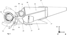
Figure 4 is a top view of the inertial system ofFigure 1 , the first inertial mass and the second inertial mass are in their respective rest positions and in which the housing, the primary rotation axis and the dampening means have been removed ; -
Figure 5 is a view similar toFigure 2 , the first inertial mass being in its blocking position and the second inertial mass being in its rest position ; -
Figure 6 is view similar toFigure 4 , the first inertial mass being in its blocking position and the second inertial mass being in its rest position ; -
Figure 7 is a view similar toFigure 2 , the first inertial mass being in its rest position and the second inertial mass being in its blocking position ; -
Figure 8 is view similar toFigure 4 , the first inertial mass being in its rest position and the second inertial mass being in its blocking position. - A vehicle
door handle assembly 10 according a particular embodiment of the invention has been shown onFigure 1 . - The vehicle
door handle assembly 10 comprises adoor handle 12, which here is known from the prior art, and usually comprises a bracket (not shown for the sake of comprehension) onto which is affixed aninertial system 14. -
Inertial system 14 comprises alocking device 16 configured to prevent the actuation of thedoor handle 12 upon activation.Inertial system 14 is protected by ahousing 15 which here is substantially parallelepipedal in shape, but this may vary. - Locking device comprises a locking
body 18 that is mounted pivotably on aprimary rotation axis 20. Considering the orientation of the Figures and the frame shown on those Figures,primary rotation axis 20 extends along axis Z. - In the example shown on the Figures, and is more particularly shown on
Figure 2 , lockingbody 18 is substantially cylindrical in shape and is hollowed out (i.e. lockingbody 18 is annular) to accommodateprimary rotation axis 20. Hence, lockingbody 18 extends alongprimary rotation axis 20. In that way, lockingdevice 16 may pivot aboutprimary rotation axis 20. - Moreover, locking
device 16 comprises a lockingend 16L, a first drivenend 16D and a second drivenend 17D. - Here, the locking
end 16L and both driven ends 16D, 17D project from lockingbody 18 substantially perpendicularly toprimary rotation axis 20. - To be more specific, driven ends 16D, 17D project from locking
body 18 on the same side of theprimary rotation axis 20, while lockingend 16L is placed on the opposite side ofprimary rotation axis 18. Here, to simplify the manufacturing of lockingdevice 16, lockingbody 18, lockingend 16L and drivenend 16D are made of one piece. - To optimize the volume occupied by the
inertial system 14, lockingend 16L is located between driven ends 16D, 17D alongprimary rotation axis 20. - Locking
end 16L extends along an axis that is parallel toprimary rotation axis 20. Lockingend 16L here has a trapezoidal section, but other sections could be envisioned. At any rate, preferably lockingend 16L comprises a planar surface that comes into contact with a blockingdevice 22 that prevents opening of thehandle door 12 as will now be explained. - Both driven
end primary rotation axis 20 and extends in such a way that is longer than the whole length of lockingbody 18. Both driven ends 16L here have a trapezoidal section, but other sections could be envisioned. At any rate, preferably both driven ends 16D, 17D also comprises a planar surface for a purpose that will become apparent later on. Here first drivenend 16D is slightly longer than second drivenend 17D alongprimary rotation axis 20. - Locking
device 16 is movable between a locking position in which the lockingend 16L comes into contact with thedoor handle 12, here with a blockingdevice 22 to prevent actuation of thedoor handle 12, and a rest position in which the lockingend 16L is not in contact with thedoor handle 12 via the blockingdevice 22. - The movement according to which the
locking device 16 moves between the rest and the locking position is a pivoting movement. Here, said pivoting movement is about primaryrotary axis 20. -
Inertial system 14 also comprises a first pivotingpart 24 pivoting aboutprimary rotation axis 20. First pivotingpart 24 is located facing first drivenend 16D. - In the embodiment shown on the Figures, and more particularly as shown on
Figures 2 and3 , first pivotingpart 24 comprises afirst body 28 linking afixed end 24E mounted on theprimary rotation axis 20 to a firstmass end 24M supporting a firstinertial mass 26. In other words, first pivotingpart 24 is lever-shaped. - In the present example, fixed
end 24E is substantially cylindrical and is hollowed-out (i.e.fixed end 24E is annular) to accommodate first pivotingaxis 20, much like lockingbody 18. Hence fixedend 24E extends alongprimary rotation axis 20. However, compared to lockingbody 18, fixedend 24E extends along a smaller portion of the length ofprimary rotation axis 20. - First
inertial mass 26 may be provided with a socket in which abumper 27 can be inserted. For example,bumper 27 may be made of rubber or any comparable material and injected in the socket.Bumper 27 reduces the noise impact ofinertial masses 26 when it moves about and hits its position stop. This movement will be explained later on. - First pivoting
part 24 also comprises afirst driving end 24D, visible onFigure 3 , which here projects from firstinertial mass 26 towards drivenend 16D so as to face it. Considering the configuration shown onFigures 2 and3 , first drivingend 24D extends perpendicularly toprimary rotation axis 20. - Driven
end 16D of the locking device may be contact, here via its planar surface, with first drivingend 24, and is also driven byfirst body 28 as will be explained now. - Indeed, first
inertial mass 26 is configured such that, when subjected to an inertial force (noted F1 onFigure 6 ) acting in a first acceleration direction, is configured to move along a first movement direction from a rest position, shown onFigures 2 ,3 and4 , allowing the opening of the door by actuation of thedoor handle 12, to a locking position, shown onFigures 5 and6 , activating thelocking device 16. - Considering the orientation of the Figures and the frame represented on said Figures, the first acceleration direction is the opposite direction of axis Y
- Here, the initial first movement direction is also the direction of axis Y, the overall movement of first
inertial mass 26 being a rotational movement about first pivotingaxis 20. Said rotational movement is in a counter clockwise direction in the example shown on the Figures. - Hence, due to the contact between the first driven
end 16D of thelocking device 16 and first drivingend 24D, the movement between the rest and locking position of thelocking device 16 and vice versa is driven by a force applied by the firstinertial mass 26 onto the first drivenend 16D. -
Inertial system 14 also comprises asecondary rotation axis 30 and asecond pivoting part 32 pivoting about saidsecondary rotation axis 30. Second pivotingpart 32 is located facing first drivenend 16D. -
Secondary rotation axis 30 here is parallel tofirst rotation axis 20. - Second pivoting
part 32 comprises asecond body 33 linking a drivingend 32D and a secondinertial mass 34.Second body 33 is hollowed-out to accommodate mounted on thesecondary rotation axis 30 such. Thesecond driving end 32D and the second mass end are thus located from either side of thesecondary rotation axis 30. - Second driven
end 17D of the locking device may be in contact with and driven by the drivingend 32D of second pivotingpart 32. - . Second
inertial mass 34 may also be provided with a bumper much like firstinertial mass 26. - When subjected to an acceleration force (noted F2 on
Figure 8 ) acting in a second acceleration direction opposite the first acceleration direction, secondinertial mass 34 is configured to move along a second movement direction, from a rest position, shown onFigures 3 and4 , allowing the opening of the door by actuation of thedoor handle 12 to a locking position activating thelocking device 18. - Considering the orientation of the Figures and the frame represented on said Figures, the second acceleration direction is the direction of axis Y
- The second movement direction, i.e. the direction along which the second
inertial mass 26 moves from its rest position to its locking position, is opposite the first movement direction of the firstinertial mass 26. - Here, the initial second movement direction is also the direction opposite of axis Y, the overall movement of second
inertial mass 34 being a rotational movement aboutsecondary rotation axis 30. Said rotational movement is in a clockwise direction in the example shown on the Figures. - Hence, due to the contact between
driven end 17D of the locking device and drivingend 32D of the second pivoting part, the movement between the rest and locking position of thelocking device 16 and vice versa is driven by a force applied by the secondinertial mass 34 onto the drivenend 17D. - So as to facilitate the reversibility of the
inertial system 14 by helping the firstinertial mass 26 to revert to its rest position, theinertial system 14 also comprises first elastic means 36 which are in a minimal tensile stress state when thelocking device 16 is in rest position, and is configured to apply a force or torque on thelocking device 16, to bring said lockingdevice 16 from the locking position back in rest position. - In the present case, as shown on
Figure 2 , first elastic means 36 include a spring, visible onFigures 3 ,4 and8 , coiled aboutprimary rotation axis 20 on its first end, as is known by the skilled person. To be more specific,spring 36 acts more particularly between lockingdevice 16 andhousing 15, to which it is connected at its other end. - In the same way, to facilitate the reversibility of the inertial system by helping the second
inertial mass 34 revert to its rest position, theinertial system 14 also comprises second elastic means 38 which are in a minimal tensile stress state when the secondinertial mass 34 is in rest position, and configured to apply a force or torque on the secondinertial mass 34, to bring saidinertial mass 34 from the locking position back in rest position. - In the present case, as shown on
Figures 2 to 8 , second elastic means 38 include a spring coiled aboutsecondary rotation axis 30, as is known by the skilled person. To be more specific,spring 38 acts more particularly between secondinertial mass 34 andsupport 15, to which it is connected at its other end as can be seen onFigure 2 . - In the configuration as shown on the Figures, first
inertial mass 26 is directly pushed back in rest position by lockingdevice 16, in order to minimize the number of elastic means. - However, in a non-represented embodiment, to further facilitate the reversibility of the inertial system by helping locking
device 16 to revert to its rest position, the inertial system for example may also comprises third elastic means which are in a minimal tensile stress state when the firstinertial mass 26 is in rest position, and configured to apply a force or torque on thelocking device 16, to bring said firstinertial mass 26 from the locking position back in rest position. - In order to prevent the
locking device 16 from going back to its rest position too rapidly, i.e. to ensure that the door stays locked during the whole duration of the crash, theinertial system 14 also comprises dampeningmeans 40. - Dampening means 40 preferably is unidirectional damper, for example a unidirectional oil damper. Dampening means 40 are free to rotate when the
locking device 16 rotates from the rest position towards the locking positions so as to not hinder the movement of the locking device when it rotates from the rest position to the locking position. However, when thelocking device 16 rotates from the blocking position towards the rest position, dampening means 40 delays this movement. and is dumped when come back. The dampening effect could be obtained with different systems such as ones using magnets or friction. - Preferably, dampening means 40 delay the bringing back of the locking device from the locking position back to the rest position by a predetermined period of time, preferably above least 0,5s, for example between 0,5s and 1s. The predetermined period of time is chosen to correspond to a nominal crash duration, which usually lasts less than a second. The delay is given by the relation between the dampening torque of the damper and the torque of the first elastic means, here
spring 36. - The way the
inertial system 14 operates will now briefly explained. - Under high accelerations (crash conditions) the
masses respective axes end locking device 16, make thelocking device 16 pivot until it reaches the blockingdevice 22 which prevents the door handle 12 from being actuated and thus the vehicle door from being opened. - To be more precise, under a force F1 along a first acceleration direction as shown on
Figures 5 and6 , firstinertial mass 26 pivots aboutprimary rotation axis 20 along a first movement direction, driving lockingdevice 16 such that it comes into contact with blockingdevice 22. Then, first elastic means 36make locking device 16 come back to its rest position shown onFigures 2 to 4 . However, dampening means 40 are provided such that lockingdevice 16 comes back to its rest position only after a predetermined period of time, which for example corresponds to a nominal crash time, to ensure the locking of the door lasts long enough. By going back to its rest position, lockingdevice 16 also drives first inertial 26 back into its rest position. - Under a force F2 along a second acceleration direction that is opposite the first acceleration as shown on
Figures 7 and8 , secondinertial mass 34 pivots aboutsecondary rotation axis 30 along a second movement direction that is opposite the first movement direction, driving lockingdevice 16 such that it comes into contact with blockingdevice 22. Then, first elastic means 36make locking device 16 come back to its rest position shown onFigures 2 to 4 as well as second elastic means 38 make secondinertial mass 34 come back to its rest position shown onFigure 2 to 4 . However, dampening means 40 are provided such that lockingdevice 16 comes back to its rest position only after a predetermined period of time, which for example corresponds to a nominal crash time, to ensure the locking of the door lasts long enough. Second elastic means 38 also make secondinertial mass 34 come back to its rest position shown onFigures 2 to 4 . - Thus one clearly understands that thanks to the presence of not one, but the two
inertial masses inertial system 14 may act like a reversible inertial system with high sensitivity, all the while having a predictable behaviour in case of rebounds. In the case of a crash, the initial acceleration due to the impact will trigger the movement of either one of themasses - Then, in the case of a rebound, even if a subsequent acceleration occurs along an opposite direction, it will not cause the unlocking of the door as it will trigger the movement of the
second mass 34, thus maintaining the blocking of the actuation of thedoor handle assembly 10. - In addition, owing to the fact that the
masses masses primary rotation axis 20 and be lodged inside asmall housing 15. -
- 10 : Vehicle door handle assembly
- 12 : Door handle
- 14 : Inertial system
- 15 : Inertial system housing
- 16 : Locking device
- 16D : First driven end of the locking device
- 16L : Locking end of the locking device
- 17D : Second driven end of the locking device
- 18 : Locking body
- 20 : Primary rotation axis
- 22 : Blocking device
- 24 : First pivoting part
- 24D: First driving end
- 24E : Fixed end of the first pivoting part
- 24M : Mass end of the first pivoting part
- 26 : First inertial mass
- 27 : Mass bumpers
- 28 : First body
- 30 : Secondary rotation axis
- 32 : Second pivoting part
- 32D : Second driving end
- 33 : Second body
- 34 : Second inertial mass
- 36 : First elastic means
- 38 : Second elastic means
- 40 : Dampening means
Claims (15)
- Inertial system (14) for a vehicle door handle assembly (10) comprising :- a locking device (16) configured to prevent the actuation of the door handle (12) upon activation,- a first inertial mass (26), which, when subjected to an acceleration force acting in a first acceleration direction, is configured to move along a first movement direction from a rest position allowing the opening of the door by actuation of the door handle (12), to a locking position activating the locking device (16),characterized in that it also comprises a second inertial mass (34), which, when subjected to an acceleration force acting in a second acceleration direction opposite the first acceleration direction, is configured to move along a second movement direction, from a rest position allowing the opening of the door by actuation of the door handle (12) to a locking position activating the locking device (16), the first movement direction being opposite the second movement direction.
- Inertial system (14) according to claim 1, wherein the locking device (16) comprises a locking end (16L) and at least a driven end (16D, 17D), the locking device (16) being movable between a locking position in which the locking end (16L) comes into contact with the door handle (12), for example via a blocking device, to prevent actuation of the door handle (12) and a rest position into which the locking end (16L) is not in contact with the door handle (12), for example via the blocking device, the movement between the rest and locking position and vice versa being driven by a force applied by a driving end (24D, 32D) that is linked to the first and/or second inertial mass (26, 34) onto the driven end (16D).
- Inertial system (14) according to claim 2, wherein the movement according to which the locking device (16) moves between the rest and the locking position is a pivoting movement.
- Inertial system (14) according to any one of the preceding claims, comprising a primary rotation axis (20) and a first pivoting part (24) pivoting about said primary rotation axis (20), the first inertial mass (26) being supported by said first pivoting part (24).
- Inertial system (14) according to claims 3 and 4 taken in combination, wherein the locking device (16) is supported by the primary rotation axis (20) and its rotational movement is a pivoting movement about the primary rotation axis (20).
- Inertial system (14) according to claim 4 or 5, wherein the first pivoting part (24) comprises a first body (28) linking a fixed end (24E) mounted on the primary rotation axis (20) to a first mass end (24M) supporting the first inertial mass (26).
- Inertial system (14) according to claims 5 and 6 taken in combination, wherein the driven end (16D) is driven by the first body (28).
- Inertial system (14) according to claim 4, comprising a secondary rotation axis (30) and a second pivoting part (32) pivoting about said secondary rotation axis (30), the second inertial mass (34) being supported by said second pivoting part (32).
- Inertial system (14) according to claim 8, wherein the second pivoting part (32) comprises a second driving end (32D) and a second mass end (32M), the driving end (32D) and the second mass end (32M) being located from either side of the secondary rotation axis (30).
- Inertial system (14) according to any one of claims 2 to 9, wherein the locking device (16) comprises a first driven end (16D) and a second driven end (17D), the movement between the rest and locking position and vice versa being driven by a force applied by a first driving end (24D) that is linked to the first inertial mass (26) onto the first driven end (16D) or a force applied by a second driving end (32D) that is linked to the second inertial mass (34) onto the second driven end (17D).
- Inertial system (14) according to claims 9 and 10 taken in combination, wherein the second driven end (17D) is driven by the second driving end (32D).
- Inertial system (14) according to any one of the preceding claims, also comprising first elastic means (36), said first elastic means (36) being in a minimal tensile stress state when the locking device (16) is in rest position, and configured to apply a force or torque on the locking device (16), to bring said locking device (16) from the locking position back in rest position.
- Inertial system (14) according to any one of the preceding claims, also comprising second elastic means (38), said second elastic means (38) being in a minimal tensile stress state when the second inertial mass (34) is in rest position, and configured to apply a force or torque on the second inertial mass (34), to bring said second inertial mass (34) from the locking position back in rest position.
- Inertial system (14) according to any one of the preceding claims, also comprising dampening means (40), said dampening means (40) delaying the bringing back of the locking device (16) from the locking position back to the rest position by a predetermined period of time, preferably above least 0,5s, for example between 0,5s and 1s.
- Inertial system (14) according to any one of the preceding claims, wherein at least one of the first (26) and second (34) inertial masses comprises a socket in which a bumper (27) can be inserted, said bumper (27) being preferably made out of rubber and injected in the socket.
Priority Applications (6)
| Application Number | Priority Date | Filing Date | Title |
|---|---|---|---|
| EP21214906.6A EP4198227B1 (en) | 2021-12-15 | 2021-12-15 | Inertial safety system for a vehicle door handle |
| ES21214906T ES3014738T3 (en) | 2021-12-15 | 2021-12-15 | Inertial safety system for a vehicle door handle |
| JP2024535630A JP2024544279A (en) | 2021-12-15 | 2022-12-13 | Inertial safety system for vehicle door handles |
| CN202280082553.9A CN118401731A (en) | 2021-12-15 | 2022-12-13 | Inertial safety system for a vehicle door handle |
| US18/716,168 US20250034913A1 (en) | 2021-12-15 | 2022-12-13 | Inertial safety system for a vehicle door handle |
| PCT/EP2022/085667 WO2023110902A1 (en) | 2021-12-15 | 2022-12-13 | Inertial safety system for a vehicle door handle |
Applications Claiming Priority (1)
| Application Number | Priority Date | Filing Date | Title |
|---|---|---|---|
| EP21214906.6A EP4198227B1 (en) | 2021-12-15 | 2021-12-15 | Inertial safety system for a vehicle door handle |
Publications (2)
| Publication Number | Publication Date |
|---|---|
| EP4198227A1 EP4198227A1 (en) | 2023-06-21 |
| EP4198227B1 true EP4198227B1 (en) | 2024-12-04 |
Family
ID=79024267
Family Applications (1)
| Application Number | Title | Priority Date | Filing Date |
|---|---|---|---|
| EP21214906.6A Active EP4198227B1 (en) | 2021-12-15 | 2021-12-15 | Inertial safety system for a vehicle door handle |
Country Status (6)
| Country | Link |
|---|---|
| US (1) | US20250034913A1 (en) |
| EP (1) | EP4198227B1 (en) |
| JP (1) | JP2024544279A (en) |
| CN (1) | CN118401731A (en) |
| ES (1) | ES3014738T3 (en) |
| WO (1) | WO2023110902A1 (en) |
Families Citing this family (2)
| Publication number | Priority date | Publication date | Assignee | Title |
|---|---|---|---|---|
| FR3152822B1 (en) * | 2023-09-07 | 2025-08-15 | Psa Automobiles Sa | Motor vehicle window opening control |
| USD1128551S1 (en) * | 2024-10-22 | 2026-06-02 | Scout Motors Inc. | Vehicle door handle |
Family Cites Families (12)
| Publication number | Priority date | Publication date | Assignee | Title |
|---|---|---|---|---|
| ITMI20022250A1 (en) | 2002-10-23 | 2004-04-24 | Valeo Sicurezza Abitacolo Spa | DOOR HANDLE, DOORS OR SIMILAR, IN PARTICULAR |
| ITRM20040337A1 (en) | 2004-07-07 | 2004-10-07 | Valeo Sicurezza Abitacolo Spa | DOOR HANDLE, IN PARTICULAR OF THE VEHICLE, WITH INERTIAL SAFETY SYSTEM. |
| FR2876135B1 (en) * | 2004-10-06 | 2011-04-29 | Peugeot Citroen Automobiles Sa | DEVICE FOR CONTROLLING THE OPENING MECHANISM OF AN OPENING OF A MOTOR VEHICLE, AND METHOD FOR MOUNTING THE DEVICE |
| DE102006025719A1 (en) * | 2006-06-02 | 2007-12-06 | Kiekert Ag | Closure device for motor vehicle, has damping unit comprising dispersion, gel and reversible casing and connected with unit in form fit or firmly-bonded manner, where unit has layer which has receiver for damping unit |
| ITRM20060660A1 (en) | 2006-12-06 | 2008-06-07 | Valeo Sicurezza Abitacolo Spa | HANDLE FOR VEHICLES WITH SAFETY DEVICE |
| IT1394303B1 (en) * | 2009-05-21 | 2012-06-06 | Valeo Spa | DOOR HANDLE OF MOTOR VEHICLE |
| DE102009058751A1 (en) * | 2009-11-06 | 2011-05-12 | Bayerische Motoren Werke Aktiengesellschaft | Actuator for door lock of motor vehicle door, has safety device that has time delay element, through which movement of safety element takes place from safety position to unlocking position with time delay |
| US8366159B2 (en) * | 2010-01-06 | 2013-02-05 | Ford Global Technologies, Llc | Multi-lever bi-directional inertia catch mechanism |
| ITMI20111130A1 (en) * | 2011-06-21 | 2012-12-22 | Valeo Spa | SAFETY DEVICE FOR A VEHICLE DOOR HANDLE. |
| EP2735676B1 (en) * | 2012-11-20 | 2017-02-15 | U-Shin Italia S.p.A. | Vehicle panel handle assembly |
| DE102013106618A1 (en) | 2013-06-25 | 2015-01-08 | Huf Hülsbeck & Fürst Gmbh & Co. Kg | Door handle assembly for a motor vehicle |
| JP2017133318A (en) * | 2016-01-29 | 2017-08-03 | アイシン精機株式会社 | Outside handle device |
-
2021
- 2021-12-15 EP EP21214906.6A patent/EP4198227B1/en active Active
- 2021-12-15 ES ES21214906T patent/ES3014738T3/en active Active
-
2022
- 2022-12-13 CN CN202280082553.9A patent/CN118401731A/en active Pending
- 2022-12-13 JP JP2024535630A patent/JP2024544279A/en active Pending
- 2022-12-13 US US18/716,168 patent/US20250034913A1/en active Pending
- 2022-12-13 WO PCT/EP2022/085667 patent/WO2023110902A1/en not_active Ceased
Also Published As
| Publication number | Publication date |
|---|---|
| US20250034913A1 (en) | 2025-01-30 |
| CN118401731A (en) | 2024-07-26 |
| JP2024544279A (en) | 2024-11-28 |
| EP4198227A1 (en) | 2023-06-21 |
| WO2023110902A1 (en) | 2023-06-22 |
| ES3014738T3 (en) | 2025-04-24 |
Similar Documents
| Publication | Publication Date | Title |
|---|---|---|
| US9856675B2 (en) | Safety device for vehicle door handle | |
| US8840156B2 (en) | Handle for a door leaf of an automobile | |
| US20250034913A1 (en) | Inertial safety system for a vehicle door handle | |
| US20050012345A1 (en) | Outside handle assembly of automobile | |
| EP2687653B1 (en) | Safety device for vehicle door handle | |
| US10829963B2 (en) | Actuating device for a motor vehicle lock | |
| KR101971749B1 (en) | Safety device for vehicle door handle | |
| KR102541353B1 (en) | Vehicle safety device with rotary latch and guard position | |
| CN114059861A (en) | Reversible and irreversible inertia safety locking and unlocking control device | |
| JP5601837B2 (en) | Vehicle handle with safety device | |
| JP6695339B2 (en) | Latch for car door | |
| US10577837B2 (en) | Lock for a motor vehicle | |
| CN111794614A (en) | Handle system with safety device | |
| KR101755828B1 (en) | A door latch link structure for preventing door opening | |
| CN110073070B (en) | Frameless door handle assembly with modular inertial locking mechanism | |
| JP2017538879A (en) | Car door latch | |
| EP1063375A1 (en) | Inertial blocking mechanism for use with an exit device | |
| KR0118186Y1 (en) | Door latch locking device |
Legal Events
| Date | Code | Title | Description |
|---|---|---|---|
| PUAI | Public reference made under article 153(3) epc to a published international application that has entered the european phase |
Free format text: ORIGINAL CODE: 0009012 |
|
| STAA | Information on the status of an ep patent application or granted ep patent |
Free format text: STATUS: THE APPLICATION HAS BEEN PUBLISHED |
|
| AK | Designated contracting states |
Kind code of ref document: A1 Designated state(s): AL AT BE BG CH CY CZ DE DK EE ES FI FR GB GR HR HU IE IS IT LI LT LU LV MC MK MT NL NO PL PT RO RS SE SI SK SM TR |
|
| STAA | Information on the status of an ep patent application or granted ep patent |
Free format text: STATUS: REQUEST FOR EXAMINATION WAS MADE |
|
| 17P | Request for examination filed |
Effective date: 20231130 |
|
| RBV | Designated contracting states (corrected) |
Designated state(s): AL AT BE BG CH CY CZ DE DK EE ES FI FR GB GR HR HU IE IS IT LI LT LU LV MC MK MT NL NO PL PT RO RS SE SI SK SM TR |
|
| GRAP | Despatch of communication of intention to grant a patent |
Free format text: ORIGINAL CODE: EPIDOSNIGR1 |
|
| RIC1 | Information provided on ipc code assigned before grant |
Ipc: E05B 77/42 20140101ALN20240131BHEP Ipc: E05B 85/14 20140101ALI20240131BHEP Ipc: E05B 77/06 20140101AFI20240131BHEP |
|
| STAA | Information on the status of an ep patent application or granted ep patent |
Free format text: STATUS: GRANT OF PATENT IS INTENDED |
|
| INTG | Intention to grant announced |
Effective date: 20240307 |
|
| RAP3 | Party data changed (applicant data changed or rights of an application transferred) |
Owner name: MINEBEA ACCESSSOLUTIONS ITALIA S.P.A. |
|
| GRAJ | Information related to disapproval of communication of intention to grant by the applicant or resumption of examination proceedings by the epo deleted |
Free format text: ORIGINAL CODE: EPIDOSDIGR1 |
|
| STAA | Information on the status of an ep patent application or granted ep patent |
Free format text: STATUS: REQUEST FOR EXAMINATION WAS MADE |
|
| GRAP | Despatch of communication of intention to grant a patent |
Free format text: ORIGINAL CODE: EPIDOSNIGR1 |
|
| STAA | Information on the status of an ep patent application or granted ep patent |
Free format text: STATUS: GRANT OF PATENT IS INTENDED |
|
| INTC | Intention to grant announced (deleted) | ||
| RIC1 | Information provided on ipc code assigned before grant |
Ipc: E05B 77/42 20140101ALN20240708BHEP Ipc: E05B 85/14 20140101ALI20240708BHEP Ipc: E05B 77/06 20140101AFI20240708BHEP |
|
| INTG | Intention to grant announced |
Effective date: 20240731 |
|
| GRAS | Grant fee paid |
Free format text: ORIGINAL CODE: EPIDOSNIGR3 |
|
| GRAA | (expected) grant |
Free format text: ORIGINAL CODE: 0009210 |
|
| STAA | Information on the status of an ep patent application or granted ep patent |
Free format text: STATUS: THE PATENT HAS BEEN GRANTED |
|
| AK | Designated contracting states |
Kind code of ref document: B1 Designated state(s): AL AT BE BG CH CY CZ DE DK EE ES FI FR GB GR HR HU IE IS IT LI LT LU LV MC MK MT NL NO PL PT RO RS SE SI SK SM TR |
|
| REG | Reference to a national code |
Ref country code: CH Ref legal event code: EP |
|
| REG | Reference to a national code |
Ref country code: DE Ref legal event code: R096 Ref document number: 602021022792 Country of ref document: DE |
|
| REG | Reference to a national code |
Ref country code: IE Ref legal event code: FG4D |
|
| REG | Reference to a national code |
Ref country code: LT Ref legal event code: MG9D |
|
| REG | Reference to a national code |
Ref country code: NL Ref legal event code: MP Effective date: 20241204 |
|
| PG25 | Lapsed in a contracting state [announced via postgrant information from national office to epo] |
Ref country code: HR Free format text: LAPSE BECAUSE OF FAILURE TO SUBMIT A TRANSLATION OF THE DESCRIPTION OR TO PAY THE FEE WITHIN THE PRESCRIBED TIME-LIMIT Effective date: 20241204 |
|
| PG25 | Lapsed in a contracting state [announced via postgrant information from national office to epo] |
Ref country code: FI Free format text: LAPSE BECAUSE OF FAILURE TO SUBMIT A TRANSLATION OF THE DESCRIPTION OR TO PAY THE FEE WITHIN THE PRESCRIBED TIME-LIMIT Effective date: 20241204 |
|
| PG25 | Lapsed in a contracting state [announced via postgrant information from national office to epo] |
Ref country code: BG Free format text: LAPSE BECAUSE OF FAILURE TO SUBMIT A TRANSLATION OF THE DESCRIPTION OR TO PAY THE FEE WITHIN THE PRESCRIBED TIME-LIMIT Effective date: 20241204 |
|
| PG25 | Lapsed in a contracting state [announced via postgrant information from national office to epo] |
Ref country code: NO Free format text: LAPSE BECAUSE OF FAILURE TO SUBMIT A TRANSLATION OF THE DESCRIPTION OR TO PAY THE FEE WITHIN THE PRESCRIBED TIME-LIMIT Effective date: 20250304 |
|
| PG25 | Lapsed in a contracting state [announced via postgrant information from national office to epo] |
Ref country code: LV Free format text: LAPSE BECAUSE OF FAILURE TO SUBMIT A TRANSLATION OF THE DESCRIPTION OR TO PAY THE FEE WITHIN THE PRESCRIBED TIME-LIMIT Effective date: 20241204 Ref country code: GR Free format text: LAPSE BECAUSE OF FAILURE TO SUBMIT A TRANSLATION OF THE DESCRIPTION OR TO PAY THE FEE WITHIN THE PRESCRIBED TIME-LIMIT Effective date: 20250305 |
|
| REG | Reference to a national code |
Ref country code: ES Ref legal event code: FG2A Ref document number: 3014738 Country of ref document: ES Kind code of ref document: T3 Effective date: 20250424 |
|
| PG25 | Lapsed in a contracting state [announced via postgrant information from national office to epo] |
Ref country code: IT Free format text: LAPSE BECAUSE OF NON-PAYMENT OF DUE FEES Effective date: 20241215 |
|
| PG25 | Lapsed in a contracting state [announced via postgrant information from national office to epo] |
Ref country code: RS Free format text: LAPSE BECAUSE OF FAILURE TO SUBMIT A TRANSLATION OF THE DESCRIPTION OR TO PAY THE FEE WITHIN THE PRESCRIBED TIME-LIMIT Effective date: 20250304 |
|
| PG25 | Lapsed in a contracting state [announced via postgrant information from national office to epo] |
Ref country code: NL Free format text: LAPSE BECAUSE OF FAILURE TO SUBMIT A TRANSLATION OF THE DESCRIPTION OR TO PAY THE FEE WITHIN THE PRESCRIBED TIME-LIMIT Effective date: 20241204 |
|
| REG | Reference to a national code |
Ref country code: AT Ref legal event code: MK05 Ref document number: 1748329 Country of ref document: AT Kind code of ref document: T Effective date: 20241204 |
|
| PG25 | Lapsed in a contracting state [announced via postgrant information from national office to epo] |
Ref country code: SM Free format text: LAPSE BECAUSE OF FAILURE TO SUBMIT A TRANSLATION OF THE DESCRIPTION OR TO PAY THE FEE WITHIN THE PRESCRIBED TIME-LIMIT Effective date: 20241204 |
|
| PG25 | Lapsed in a contracting state [announced via postgrant information from national office to epo] |
Ref country code: PL Free format text: LAPSE BECAUSE OF FAILURE TO SUBMIT A TRANSLATION OF THE DESCRIPTION OR TO PAY THE FEE WITHIN THE PRESCRIBED TIME-LIMIT Effective date: 20241204 |
|
| PG25 | Lapsed in a contracting state [announced via postgrant information from national office to epo] |
Ref country code: IS Free format text: LAPSE BECAUSE OF FAILURE TO SUBMIT A TRANSLATION OF THE DESCRIPTION OR TO PAY THE FEE WITHIN THE PRESCRIBED TIME-LIMIT Effective date: 20250404 |
|
| PG25 | Lapsed in a contracting state [announced via postgrant information from national office to epo] |
Ref country code: PT Free format text: LAPSE BECAUSE OF FAILURE TO SUBMIT A TRANSLATION OF THE DESCRIPTION OR TO PAY THE FEE WITHIN THE PRESCRIBED TIME-LIMIT Effective date: 20250404 |
|
| PG25 | Lapsed in a contracting state [announced via postgrant information from national office to epo] |
Ref country code: EE Free format text: LAPSE BECAUSE OF FAILURE TO SUBMIT A TRANSLATION OF THE DESCRIPTION OR TO PAY THE FEE WITHIN THE PRESCRIBED TIME-LIMIT Effective date: 20241204 |
|
| PG25 | Lapsed in a contracting state [announced via postgrant information from national office to epo] |
Ref country code: RO Free format text: LAPSE BECAUSE OF FAILURE TO SUBMIT A TRANSLATION OF THE DESCRIPTION OR TO PAY THE FEE WITHIN THE PRESCRIBED TIME-LIMIT Effective date: 20241204 Ref country code: AT Free format text: LAPSE BECAUSE OF FAILURE TO SUBMIT A TRANSLATION OF THE DESCRIPTION OR TO PAY THE FEE WITHIN THE PRESCRIBED TIME-LIMIT Effective date: 20241204 |
|
| PG25 | Lapsed in a contracting state [announced via postgrant information from national office to epo] |
Ref country code: SK Free format text: LAPSE BECAUSE OF FAILURE TO SUBMIT A TRANSLATION OF THE DESCRIPTION OR TO PAY THE FEE WITHIN THE PRESCRIBED TIME-LIMIT Effective date: 20241204 |
|
| PG25 | Lapsed in a contracting state [announced via postgrant information from national office to epo] |
Ref country code: CZ Free format text: LAPSE BECAUSE OF FAILURE TO SUBMIT A TRANSLATION OF THE DESCRIPTION OR TO PAY THE FEE WITHIN THE PRESCRIBED TIME-LIMIT Effective date: 20241204 |
|
| REG | Reference to a national code |
Ref country code: CH Ref legal event code: PL |
|
| PG25 | Lapsed in a contracting state [announced via postgrant information from national office to epo] |
Ref country code: LU Free format text: LAPSE BECAUSE OF NON-PAYMENT OF DUE FEES Effective date: 20241215 |
|
| REG | Reference to a national code |
Ref country code: DE Ref legal event code: R097 Ref document number: 602021022792 Country of ref document: DE |
|
| PG25 | Lapsed in a contracting state [announced via postgrant information from national office to epo] |
Ref country code: SE Free format text: LAPSE BECAUSE OF FAILURE TO SUBMIT A TRANSLATION OF THE DESCRIPTION OR TO PAY THE FEE WITHIN THE PRESCRIBED TIME-LIMIT Effective date: 20241204 |
|
| PG25 | Lapsed in a contracting state [announced via postgrant information from national office to epo] |
Ref country code: MC Free format text: LAPSE BECAUSE OF FAILURE TO SUBMIT A TRANSLATION OF THE DESCRIPTION OR TO PAY THE FEE WITHIN THE PRESCRIBED TIME-LIMIT Effective date: 20241204 |
|
| REG | Reference to a national code |
Ref country code: BE Ref legal event code: MM Effective date: 20241231 |
|
| PG25 | Lapsed in a contracting state [announced via postgrant information from national office to epo] |
Ref country code: DK Free format text: LAPSE BECAUSE OF FAILURE TO SUBMIT A TRANSLATION OF THE DESCRIPTION OR TO PAY THE FEE WITHIN THE PRESCRIBED TIME-LIMIT Effective date: 20241204 |
|
| PLBE | No opposition filed within time limit |
Free format text: ORIGINAL CODE: 0009261 |
|
| STAA | Information on the status of an ep patent application or granted ep patent |
Free format text: STATUS: NO OPPOSITION FILED WITHIN TIME LIMIT |
|
| PG25 | Lapsed in a contracting state [announced via postgrant information from national office to epo] |
Ref country code: BE Free format text: LAPSE BECAUSE OF NON-PAYMENT OF DUE FEES Effective date: 20241231 |
|
| PG25 | Lapsed in a contracting state [announced via postgrant information from national office to epo] |
Ref country code: CH Free format text: LAPSE BECAUSE OF NON-PAYMENT OF DUE FEES Effective date: 20241231 |
|
| PG25 | Lapsed in a contracting state [announced via postgrant information from national office to epo] |
Ref country code: IE Free format text: LAPSE BECAUSE OF NON-PAYMENT OF DUE FEES Effective date: 20241215 |
|
| 26N | No opposition filed |
Effective date: 20250905 |
|
| PG25 | Lapsed in a contracting state [announced via postgrant information from national office to epo] |
Ref country code: IT Free format text: LAPSE BECAUSE OF NON-PAYMENT OF DUE FEES Effective date: 20241215 |
|
| PGFP | Annual fee paid to national office [announced via postgrant information from national office to epo] |
Ref country code: IT Payment date: 20251210 Year of fee payment: 5 |
|
| PGRI | Patent reinstated in contracting state [announced from national office to epo] |
Ref country code: IT Effective date: 20241231 |
|
| PGFP | Annual fee paid to national office [announced via postgrant information from national office to epo] |
Ref country code: FR Payment date: 20251230 Year of fee payment: 5 |
|
| PGFP | Annual fee paid to national office [announced via postgrant information from national office to epo] |
Ref country code: ES Payment date: 20260112 Year of fee payment: 5 |
|
| PGFP | Annual fee paid to national office [announced via postgrant information from national office to epo] |
Ref country code: DE Payment date: 20251231 Year of fee payment: 5 |
|
| PG25 | Lapsed in a contracting state [announced via postgrant information from national office to epo] |
Ref country code: CY Free format text: LAPSE BECAUSE OF FAILURE TO SUBMIT A TRANSLATION OF THE DESCRIPTION OR TO PAY THE FEE WITHIN THE PRESCRIBED TIME-LIMIT Effective date: 20241204 |
|
| PG25 | Lapsed in a contracting state [announced via postgrant information from national office to epo] |
Ref country code: TR Free format text: LAPSE BECAUSE OF FAILURE TO SUBMIT A TRANSLATION OF THE DESCRIPTION OR TO PAY THE FEE WITHIN THE PRESCRIBED TIME-LIMIT Effective date: 20241204 |
|
| PG25 | Lapsed in a contracting state [announced via postgrant information from national office to epo] |
Ref country code: HU Free format text: LAPSE BECAUSE OF FAILURE TO SUBMIT A TRANSLATION OF THE DESCRIPTION OR TO PAY THE FEE WITHIN THE PRESCRIBED TIME-LIMIT; INVALID AB INITIO Effective date: 20211215 |
|
| PG25 | Lapsed in a contracting state [announced via postgrant information from national office to epo] |
Ref country code: SI Free format text: LAPSE BECAUSE OF FAILURE TO SUBMIT A TRANSLATION OF THE DESCRIPTION OR TO PAY THE FEE WITHIN THE PRESCRIBED TIME-LIMIT Effective date: 20241204 |
|
| PG25 | Lapsed in a contracting state [announced via postgrant information from national office to epo] |
Ref country code: LT Free format text: LAPSE BECAUSE OF FAILURE TO SUBMIT A TRANSLATION OF THE DESCRIPTION OR TO PAY THE FEE WITHIN THE PRESCRIBED TIME-LIMIT Effective date: 20241204 |