EP4198212A1 - Water collection module - Google Patents
Water collection module Download PDFInfo
- Publication number
- EP4198212A1 EP4198212A1 EP21215214.4A EP21215214A EP4198212A1 EP 4198212 A1 EP4198212 A1 EP 4198212A1 EP 21215214 A EP21215214 A EP 21215214A EP 4198212 A1 EP4198212 A1 EP 4198212A1
- Authority
- EP
- European Patent Office
- Prior art keywords
- water
- module
- collection container
- collection
- base module
- Prior art date
- Legal status (The legal status is an assumption and is not a legal conclusion. Google has not performed a legal analysis and makes no representation as to the accuracy of the status listed.)
- Withdrawn
Links
- XLYOFNOQVPJJNP-UHFFFAOYSA-N water Substances O XLYOFNOQVPJJNP-UHFFFAOYSA-N 0.000 title claims abstract description 206
- 230000007246 mechanism Effects 0.000 claims description 15
- 230000008878 coupling Effects 0.000 description 4
- 238000010168 coupling process Methods 0.000 description 4
- 238000005859 coupling reaction Methods 0.000 description 4
- 238000010413 gardening Methods 0.000 description 4
- 239000000463 material Substances 0.000 description 2
- 238000004140 cleaning Methods 0.000 description 1
- 239000012530 fluid Substances 0.000 description 1
- 230000005484 gravity Effects 0.000 description 1
- 238000012423 maintenance Methods 0.000 description 1
- 238000000034 method Methods 0.000 description 1
- 229920003023 plastic Polymers 0.000 description 1
- 239000004033 plastic Substances 0.000 description 1
- 229920000642 polymer Polymers 0.000 description 1
Images



Classifications
-
- E—FIXED CONSTRUCTIONS
- E03—WATER SUPPLY; SEWERAGE
- E03B—INSTALLATIONS OR METHODS FOR OBTAINING, COLLECTING, OR DISTRIBUTING WATER
- E03B3/00—Methods or installations for obtaining or collecting drinking water or tap water
- E03B3/02—Methods or installations for obtaining or collecting drinking water or tap water from rain-water
- E03B3/03—Special vessels for collecting or storing rain-water for use in the household, e.g. water-butts
Definitions
- the present disclosure relates generally to water collection, and more specifically to a water collection module to allow easy access of collected water.
- water is captured from a roof or large planar surface area and is passed, under gravity to a storage tank at or below ground level.
- a water tank or a water collection container which may collect and store water for future usage.
- such a water collection container typically does not facilitate easy access to the stored water such that the collected water may be easily used further for various purposes.
- the '229 reference discloses a device which is used to collect water from a down spout and allows excess water to exit the down spout as originally intended.
- the down spout is cut at the top of the device allowing the down spout to transfer water to the tank of the device through a planter and water deflector device.
- the water enters the tank and fills the tank until the water reaches the spill way.
- the lower portion of the down spout is attached to the spill way so when the water enters the spill way, it travels down the down spout as originally intended.
- the tank is mounted on a base to elevate the tank for access to the water.
- the water is extracted from the tank by opening a spigot and filling a container such as a watering can.
- a soaker hose can also be attached to the bottom of the tank to water nearby plants.
- the '878 reference fails to disclose any provision for facilitating easy access to the stored water from the water tank for further usage in an ergonomic and efficient manner.
- the water collection module includes a collection container.
- the collection container is adapted to collect and store water.
- the collection container has a top portion and a bottom portion.
- the collection container defines a water outlet towards a bottom portion.
- the collection container further has at least one base module coupled to the collection container towards the bottom portion.
- the base module is adapted to allow the collection container to stand on the base module.
- the water collection module is characterized in that the at least one base module is fluidly coupled with the water outlet of the collection container, and the at least one base module houses at least one water distribution component therein.
- the present disclosure provides an improved water collection module.
- the at least one water distribution component enables easy and ergonomic access of the collected water for various applications such as gardening, kitchen uses, household purposes etc.
- the at least one water distribution component allows accessing water from the collection container without changing structural orientation of the water collection module such as decoupling the base module and the collection container. This saves any extra effort or manpower to be used for accessing water as compared to any other (say conventional) case.
- the at least one water distribution component is a hose box.
- the hose box allows accessing the collected water through a hose coupled with the hose box.
- a user may unwind the hose from the hose box and use the hose to get supply of the collected water as per application purposes.
- the water collection module may be placed on a terrace, and the user may use the hose to provide the collected water to a terrace garden.
- the at least one water distribution component is a pump.
- the pump may be used to provide water supply for household purposes, gardening purposes etc.
- the pump may be further suitably connected with a hose, or a pipeline system etc. to ensure supply of the collected water as per application requirements.
- the base element or a part thereof could be filled with water in which the pump, preferably being a submersible pump, is inserted.
- the base element or a part thereof could not be filled with water and in that empty (dry) space a pump can be located, preferably with its water inlet being fluidly coupled with the water outlet of the collection container.
- the at least one water distribution component is a pipeline system.
- the pipeline system may facilitate easy access and further supply to the collected water as per application requirements.
- the at least one water distribution component is a watering computer.
- the watering computer may provide easy access to the collected water.
- the watering computer may be further communicably coupled with a mobile device which may facilitate remote access to the collected water accordingly.
- the watering computer may be suitably programmed as per usage requirements to access the collected water.
- the at least one base module can be selected from a plurality of base modules.
- a user may be provided with multiple base modules having different functionalities to select from.
- Each of the plurality of base modules may be configured with at least one of a hose box, a pump, a pipeline system, and a watering computer.
- the user may select one or more base modules based upon his/her application requirements. For example, a user who wishes to place the water collection module in a garden may select the base module with a hose box, and the base module with a watering computer. The user may use the two or more base modules at same or different times as per application requirements in the garden.
- the collection container is fluidly coupled with the at least one base module such that flow of collected water is allowed from the collection container to the base module, provided the collection container is coupled with the base module.
- the flow of water may also be allowed from the base module to the collection container.
- the base module and the collection container may be coupled together through any suitable coupling mechanism which may allow desired flow of collected water.
- the at least one base module includes a decoupling mechanism for uncoupling the collection container and the base module. After the collection container gets coupled with the base module, it may be difficult for a user to decouple the collection container and the base module from each other.
- the base module is also provided with a decoupling mechanism.
- the decoupling mechanism may be configured within the base module.
- the decoupling mechanism may have a lever or a toggle switch to uncouple the collection container and the base module.
- the water collection module (200) comprises two or more base modules at same time. Preferably these are on top of each other in a stacked configuration. In this case the functionality of the module can be further increased and by stacking the base modules on top of each other space saving can be achieved.
- FIG. 1 illustrates a conventional water collection module 100.
- the conventional water collection module 100 is used to collect water during rainfall and like events.
- the conventional water collection module 100 may be placed at any location having access to water during rainfall.
- the conventional water collection module 100 may be placed on a terrace of a household, in a garden area, in a lawn area or any other suitable location in accordance with various aspects of the present disclosure.
- the conventional water collection module 100 is a singular structure.
- the conventional water collection module 100 has a collection container 102 which receives water. Further, the conventional water collection module 100 is provided with a water outlet 104 illustrated as a water tap to access the water collected by the collection container 102.
- the conventional water collection module 100 does not facilitate easy access to the collected water for further usage as per application requirements.
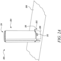
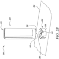
- FIGS. 2A and 2B illustrate a water collection module 200 as per the present disclosure.
- the water collection module 200 has a modular structure.
- the water collection module 200 has at least one base module 202 and a collection container 204.
- the at least one base module 202 and the collection container 204 are both provided as separate components making up the modular structure of the water collection module 200.
- the at least one base module 202 and the collection container 204 may be made of a similar or different materials such as plastics, reinforced polymer or any such material which may be suitable in accordance with various aspects of the present disclosure.
- the collection container 204 is adapted to collect and store water. More specifically, the collection container 204 receives the water during rainfall and stores the water accordingly.
- the collection container 204 has a top portion 214 and a bottom portion 216 such that the collection container 204 defines a water outlet 210 towards the bottom portion 216.
- the water outlet 210 may be any suitable type of water outlet 210 which may be shaped and sized as per application requirements.
- the collection container 204 is adapted to be placed upon the base module 202. Further, the base module 202 is adapted to be fluidly coupled with the collection container 204. The base module 202 is coupled to the collection container 204 towards the bottom portion 216 of the collection container 204. The base module defines a water inlet 218. The water inlet 218 is adapted to establish fluid coupling between the collection container 204 and the base module 202. More specifically, the water inlet 218 of the base module 202 gets coupled with the water outlet 210 of the collection container 204.
- the collection container 204 may be coupled with the base module 202 through any suitable coupling means which may allow flow of water from the collection container 204 to the base module 202. The present disclosure is not limited by any such means of coupling between the collection container 204 and the base module 202.
- the base module 202 is illustrated as a stand module 206 in FIGS. 2A and 2B .
- the stand module 206 provides a higher elevation to the collection container 204 compared to a surface 208 over which the water collection module 200 is placed upon. Higher elevation may provide a user with better access to the surface 208 under the water collection module 200 for maintenance (say cleaning) and like purposes.
- FIGS. 2A and 2B further illustrate a decoupling mechanism 212.
- the base module 202 includes the decoupling mechanism 212 for uncoupling the collection container 204 and the base module 202.
- the decoupling mechanism 212 is illustrated as a lever which may be rotated to decouple the base module 202 and the collection container 204 with each other.
- the decoupling mechanism 212 may be any other type of actuator as well such as a toggle switch.
- the lever may further be connected with various other components provided within the base module 202 which may actuate required parts to decouple the base module 202 and the collection container 204. In an embodiment, the lever may also be rotated to couple the base module 202 and the collection container 204 together.
- the decoupling mechanism 212 provides an easy and ergonomic means to decouple the base module 202 and the collection container 204.
- the decoupling mechanism 212 ay be any other type of decoupling mechanism 212 as well, and the present disclosure is not limited by any such type of mechanisms in any manner.
- the base module 202 is configured with at least one water distribution component 300 (shown in FIG. 3 onwards) to facilitate access of the water collected by the collection container 204.
- the at least one water distribution component 300 may enable easy and ergonomic access of the collected water for various applications such as gardening, kitchen uses, household purposes etc.
- the at least one water distribution component 300 may allow accessing the collected water without changing structural orientation of the water collection module 200 such as decoupling the base module 202 and the collection container 204. This saves any extra effort or manpower to be used for accessing water as compared to any other (i.e., conventional) case.
- FIG. 3 illustrates the water collection module 200 with the base module 202 having the water distribution component 300 as a hose box 302 having a hose 304.
- the hose box 302 allows accessing the collected water through a hose (not shown) coupled with the hose box 302.
- a user may unwind the hose from the hose box 302 and use the hose to get supply of the collected water as per application purposes.
- the water collection module 200 may be placed on a terrace, and the user may use the hose to provide the collected water to a terrace garden.
- FIG. 4 illustrates the water collection module 200 with the base module 202 having at least one water distribution component 300 as a pump 400.
- the pump 400 is a submersible pump that may be used to provide water supply for household purposes, gardening purposes etc.
- the submersible pump 400 may be further suitably connected with a hose, or a pipeline system etc. to ensure supply of the collected water as per application requirements.
- the water collection module 200 may be placed such that the base module 202 places the submersible pump 400 submerged underwater.
- the submersible pump 400 may be used to supply the collected water from the base module 202.
- FIG. 5 illustrates the water collection module 200 with the base module 202 having the at least one water distribution component 300 as a pipeline system 500.
- the pipeline system 500 may facilitate easy access and further supply to the collected water as per application requirements.
- the pipeline system 500 may further be integrated with existing water supply lines (not shown) and may aid water supply therein. Further, it should also be contemplated that the water may flow from the base module 202 to the collection container 204 as well and the present disclosure is not limited by flow of water in one direction only.
- the pipeline system 500 may provide water to the base module 202 and thereafter the collection container 204 and may be stored therein. The stored water may thereafter used for various purposes as per application requirements.
- the water collection module 200 further includes a water tap 502 for accessing water directly from the collection container 204.
- the water tap 502 may be any suitable type of water tap known in the prior art which may be suitable for application with various aspects of the present disclosure without limiting the scope of the present disclosure in any manner.
- FIG. 6 illustrates the water collection module 200 with the base module 202 having the at least one water distribution component 300 as a watering computer 700.
- the watering computer 700 may provide easy access to the collected water.
- the watering computer 700 may be further communicably coupled with a mobile device (not shown) which may facilitate remote access to the collected water accordingly.
- the watering computer 700 may be suitably programmed as per usage requirements to access the collected water.
- the base module 202 can be selected from a plurality of base modules 202.
- a user may be provided with multiple base modules 202 having different functionalities to select from.
- Each of the plurality of base modules 202 may be configured with at least one of the hose box 302, the pump 400, the pipeline system 500, and the watering computer 700.
- the user may select one or more base modules 202 based upon his/her application requirements. For example, a user who wishes to place the water collection module 200 in a garden may select the base module 202 with the hose box 302, and the base module 202 with the watering computer 700. The user may use the two base modules 202 at different times as per application requirements in the garden.
- FIG. 7A provides an assembled view of the water collection module 200 and FIG. 7B provides an exploded view of the water collection module 200.
- the water collection module 200 includes the collection container 204.
- the collection container 204 has the top portion 214 and the bottom portion 216 such that the collection container 204 defines the water outlet 210 towards the bottom portion 216.
- the water collection module 200 further includes one or more base modules.
- the water collection module 200 includes a first base module 802 and a second base module 804 coupled with the collection container 204 along a central axis X-X'.
- the water collection module 200 may include more than two base modules as well, and the present disclosure is not limited by number of base modules in any manner.
- the first base module 802 includes a water computer 814 as the at least one water distribution component.
- the first base module 802 includes a first water inlet 806 and a first water outlet 808.
- the first water inlet 806 is fluidly coupled with the water outlet 210 of the collection container 202.
- the second base module 804 includes a pipeline system 810 as the at least one water distribution component.
- the second base module 804 includes a second water inlet 812.
- the second water inlet 812 is fluidly coupled with the first water outlet 808.
- the water collected by the collection container 204 may get transferred to the first base module 802 and thereafter the second base module 804 along the central axis X-X' .
- the pipeline system 810 may transfer water to the second base module 804 and thereafter to the first base module 802 and may be stored within the collection container 204 to various usage purposes as per application requirements. It should be contemplated that various other logical combinations of the at least one water distribution component with the first base module 802 and the second base module 804 may also be envisioned well within the scope of the present disclosure.
Landscapes
- Engineering & Computer Science (AREA)
- Environmental & Geological Engineering (AREA)
- Health & Medical Sciences (AREA)
- Life Sciences & Earth Sciences (AREA)
- Hydrology & Water Resources (AREA)
- Public Health (AREA)
- Water Supply & Treatment (AREA)
- Sampling And Sample Adjustment (AREA)
- Details Of Rigid Or Semi-Rigid Containers (AREA)
Abstract
A water collection module (200) includes a collection container (204) to collect and store water. The collection container has a top portion and a bottom portion such that the collection container (204) defines a water outlet towards a bottom portion. At least one base module (202) is coupled to the collection container (204) towards the bottom portion. The base module (202) allows the collection container (204) to stand on the base module (202). The water collection module (200) is characterized in that the at least one base module (202) is fluidly coupled with the water outlet of the collection container (204), and the at least one base module (202) houses at least one water distribution component (300) therein.
Description
- The present disclosure relates generally to water collection, and more specifically to a water collection module to allow easy access of collected water.
- Increasingly, governments and local authorities around the world are treating water as a scarce commodity and water charges are being introduced as a means to cover the cost of treating and supplying water to residential and business properties. Water metering is already being carried out in numerous parts of the world and many of the remaining countries have plans to introduce water metering within the next five to ten years.
- Consequently, the capture and treatment of water has become of interest in recent times, in particularly if the water is rainwater. Typically, water is captured from a roof or large planar surface area and is passed, under gravity to a storage tank at or below ground level. One of the most common means to capture water is a water tank or a water collection container which may collect and store water for future usage. However, such a water collection container typically does not facilitate easy access to the stored water such that the collected water may be easily used further for various purposes.
- An example is provided by U.S. patent application
US2015/08229 (hereinafter referred to as the '229 reference). The '229 reference discloses a device which is used to collect water from a down spout and allows excess water to exit the down spout as originally intended. The down spout is cut at the top of the device allowing the down spout to transfer water to the tank of the device through a planter and water deflector device. The water enters the tank and fills the tank until the water reaches the spill way. The lower portion of the down spout is attached to the spill way so when the water enters the spill way, it travels down the down spout as originally intended. The tank is mounted on a base to elevate the tank for access to the water. The water is extracted from the tank by opening a spigot and filling a container such as a watering can. A soaker hose can also be attached to the bottom of the tank to water nearby plants. However, the '878 reference fails to disclose any provision for facilitating easy access to the stored water from the water tank for further usage in an ergonomic and efficient manner. - In view of the above, it is an objective of the present disclosure to solve or at least reduce the drawbacks discussed above. The objective is at least partially achieved by a water collection module. The water collection module includes a collection container. The collection container is adapted to collect and store water. The collection container has a top portion and a bottom portion. The collection container defines a water outlet towards a bottom portion. The collection container further has at least one base module coupled to the collection container towards the bottom portion. The base module is adapted to allow the collection container to stand on the base module. The water collection module is characterized in that the at least one base module is fluidly coupled with the water outlet of the collection container, and the at least one base module houses at least one water distribution component therein.
- Thus, the present disclosure provides an improved water collection module. The at least one water distribution component enables easy and ergonomic access of the collected water for various applications such as gardening, kitchen uses, household purposes etc. The at least one water distribution component allows accessing water from the collection container without changing structural orientation of the water collection module such as decoupling the base module and the collection container. This saves any extra effort or manpower to be used for accessing water as compared to any other (say conventional) case.
- According to an embodiment of the present disclosure, the at least one water distribution component is a hose box. The hose box allows accessing the collected water through a hose coupled with the hose box. A user may unwind the hose from the hose box and use the hose to get supply of the collected water as per application purposes. For example, the water collection module may be placed on a terrace, and the user may use the hose to provide the collected water to a terrace garden.
- According to an embodiment of the present disclosure, the at least one water distribution component is a pump. The pump may be used to provide water supply for household purposes, gardening purposes etc. The pump may be further suitably connected with a hose, or a pipeline system etc. to ensure supply of the collected water as per application requirements. In one embodiment of the present disclosure the base element or a part thereof could be filled with water in which the pump, preferably being a submersible pump, is inserted. In an alternative embodiment the base element or a part thereof could not be filled with water and in that empty (dry) space a pump can be located, preferably with its water inlet being fluidly coupled with the water outlet of the collection container.
- According to an embodiment of the present disclosure, the at least one water distribution component is a pipeline system. The pipeline system may facilitate easy access and further supply to the collected water as per application requirements.
- According to an embodiment of the present disclosure, the at least one water distribution component is a watering computer. The watering computer may provide easy access to the collected water. The watering computer may be further communicably coupled with a mobile device which may facilitate remote access to the collected water accordingly. The watering computer may be suitably programmed as per usage requirements to access the collected water.
- According to an embodiment of the present disclosure, the at least one base module can be selected from a plurality of base modules. A user may be provided with multiple base modules having different functionalities to select from. Each of the plurality of base modules may be configured with at least one of a hose box, a pump, a pipeline system, and a watering computer. The user may select one or more base modules based upon his/her application requirements. For example, a user who wishes to place the water collection module in a garden may select the base module with a hose box, and the base module with a watering computer. The user may use the two or more base modules at same or different times as per application requirements in the garden.
- According to an embodiment of the present disclosure, the collection container is fluidly coupled with the at least one base module such that flow of collected water is allowed from the collection container to the base module, provided the collection container is coupled with the base module. The flow of water may also be allowed from the base module to the collection container. The base module and the collection container may be coupled together through any suitable coupling mechanism which may allow desired flow of collected water.
- According to an embodiment of the present disclosure, the at least one base module includes a decoupling mechanism for uncoupling the collection container and the base module. After the collection container gets coupled with the base module, it may be difficult for a user to decouple the collection container and the base module from each other. Thus, the base module is also provided with a decoupling mechanism. The decoupling mechanism may be configured within the base module. The decoupling mechanism may have a lever or a toggle switch to uncouple the collection container and the base module.
- According to an embodiment of the present disclosure, the water collection module (200) comprises two or more base modules at same time. Preferably these are on top of each other in a stacked configuration. In this case the functionality of the module can be further increased and by stacking the base modules on top of each other space saving can be achieved.
- Other features and aspects of this disclosure will be apparent from the following description and the accompanying drawings.
- The disclosure will be described in more detail with reference to the enclosed drawings, wherein:
-
FIG. 1 illustrates a conventional water collection module; -
FIG. 2A illustrates a water collection module showing a base module coupled with a collection container, according to an embodiment of the present disclosure; -
FIG. 2B illustrates the water collection module showing the base module and the collection container in an exploded view, according to an embodiment of the present disclosure; -
FIG. 3 illustrates a water collection module showing a base module having a hose box, according to an embodiment of the present disclosure; -
FIG. 4 illustrates a water collection module showing a base module having a submersible pump, according to an embodiment of the present disclosure; -
FIG. 5 illustrates a water collection module showing a base module having a pipeline system, according to an embodiment of the present disclosure; -
FIG. 6 illustrates a water collection module showing a base module having a watering computer, according to an embodiment of the present disclosure; -
FIG. 7A illustrates an assembled view of a water collection module having multiple base modules, according to an embodiment of the present disclosure; and -
FIG. 7B illustrates an exploded view of the water collection module having multiple base modules, according to an embodiment of the present disclosure. - The present disclosure will be described more fully hereinafter with reference to the accompanying drawings, in which example embodiments of the disclosure incorporating one or more aspects of the present disclosure are shown. This disclosure may, however, be embodied in many different forms and should not be construed as limited to the embodiments set forth herein; rather, these embodiments are provided so that this disclosure will be thorough and complete, and will fully convey the scope of the disclosure to those skilled in the art. For example, one or more aspects of the present disclosure may be utilized in other embodiments and even other types of structures and/or methods. In the drawings, like numbers refer to like elements.
- Certain terminology is used herein for convenience only and is not to be taken as a limitation on the disclosure. For example, "upper", "lower", "front", "rear", "side", "longitudinal", "lateral", "transverse", "upwards", "downwards", "forward", "backward", "sideward", "left," "right," "horizontal," "vertical," "upward", "inner", "outer", "inward", "outward", "top", "bottom", "higher", "above", "below", "central", "middle", "intermediate", "between", "end", "adjacent", "proximate", "near", "distal", "remote", "radial", "circumferential", or the like, merely describe the configuration shown in the Figures. Indeed, the components may be oriented in any direction and the terminology, therefore, should be understood as encompassing such variations unless specified otherwise.
-
FIG. 1 illustrates a conventionalwater collection module 100. The conventionalwater collection module 100 is used to collect water during rainfall and like events. The conventionalwater collection module 100 may be placed at any location having access to water during rainfall. For example, the conventionalwater collection module 100 may be placed on a terrace of a household, in a garden area, in a lawn area or any other suitable location in accordance with various aspects of the present disclosure. - As illustrated, the conventional
water collection module 100 is a singular structure. The conventionalwater collection module 100 has acollection container 102 which receives water. Further, the conventionalwater collection module 100 is provided with awater outlet 104 illustrated as a water tap to access the water collected by thecollection container 102. However, the conventionalwater collection module 100 does not facilitate easy access to the collected water for further usage as per application requirements. -
FIGS. 2A and2B illustrate awater collection module 200 as per the present disclosure. Referring in combination toFIGS. 2A and2B , thewater collection module 200 has a modular structure. Thewater collection module 200 has at least onebase module 202 and acollection container 204. The at least onebase module 202 and thecollection container 204 are both provided as separate components making up the modular structure of thewater collection module 200. The at least onebase module 202 and thecollection container 204 may be made of a similar or different materials such as plastics, reinforced polymer or any such material which may be suitable in accordance with various aspects of the present disclosure. - The
collection container 204 is adapted to collect and store water. More specifically, thecollection container 204 receives the water during rainfall and stores the water accordingly. Thecollection container 204 has atop portion 214 and abottom portion 216 such that thecollection container 204 defines awater outlet 210 towards thebottom portion 216. Thewater outlet 210 may be any suitable type ofwater outlet 210 which may be shaped and sized as per application requirements. - The
collection container 204 is adapted to be placed upon thebase module 202. Further, thebase module 202 is adapted to be fluidly coupled with thecollection container 204. Thebase module 202 is coupled to thecollection container 204 towards thebottom portion 216 of thecollection container 204. The base module defines awater inlet 218. Thewater inlet 218 is adapted to establish fluid coupling between thecollection container 204 and thebase module 202. More specifically, thewater inlet 218 of thebase module 202 gets coupled with thewater outlet 210 of thecollection container 204. Thecollection container 204 may be coupled with thebase module 202 through any suitable coupling means which may allow flow of water from thecollection container 204 to thebase module 202. The present disclosure is not limited by any such means of coupling between thecollection container 204 and thebase module 202. - The
base module 202 is illustrated as astand module 206 inFIGS. 2A and2B . Thestand module 206 provides a higher elevation to thecollection container 204 compared to asurface 208 over which thewater collection module 200 is placed upon. Higher elevation may provide a user with better access to thesurface 208 under thewater collection module 200 for maintenance (say cleaning) and like purposes. -
FIGS. 2A and2B further illustrate adecoupling mechanism 212. Thebase module 202 includes thedecoupling mechanism 212 for uncoupling thecollection container 204 and thebase module 202. Thedecoupling mechanism 212 is illustrated as a lever which may be rotated to decouple thebase module 202 and thecollection container 204 with each other. Thedecoupling mechanism 212 may be any other type of actuator as well such as a toggle switch. - The lever may further be connected with various other components provided within the
base module 202 which may actuate required parts to decouple thebase module 202 and thecollection container 204. In an embodiment, the lever may also be rotated to couple thebase module 202 and thecollection container 204 together. Thedecoupling mechanism 212 provides an easy and ergonomic means to decouple thebase module 202 and thecollection container 204. Thedecoupling mechanism 212 ay be any other type ofdecoupling mechanism 212 as well, and the present disclosure is not limited by any such type of mechanisms in any manner. - As per the present disclosure, the
base module 202 is configured with at least one water distribution component 300 (shown inFIG. 3 onwards) to facilitate access of the water collected by thecollection container 204. The at least onewater distribution component 300 may enable easy and ergonomic access of the collected water for various applications such as gardening, kitchen uses, household purposes etc. The at least onewater distribution component 300 may allow accessing the collected water without changing structural orientation of thewater collection module 200 such as decoupling thebase module 202 and thecollection container 204. This saves any extra effort or manpower to be used for accessing water as compared to any other (i.e., conventional) case. -
FIG. 3 illustrates thewater collection module 200 with thebase module 202 having thewater distribution component 300 as ahose box 302 having ahose 304. Thehose box 302 allows accessing the collected water through a hose (not shown) coupled with thehose box 302. A user may unwind the hose from thehose box 302 and use the hose to get supply of the collected water as per application purposes. For example, thewater collection module 200 may be placed on a terrace, and the user may use the hose to provide the collected water to a terrace garden. -
FIG. 4 illustrates thewater collection module 200 with thebase module 202 having at least onewater distribution component 300 as apump 400. In case of this specific example thepump 400 is a submersible pump that may be used to provide water supply for household purposes, gardening purposes etc. Thesubmersible pump 400 may be further suitably connected with a hose, or a pipeline system etc. to ensure supply of the collected water as per application requirements. For example, thewater collection module 200 may be placed such that thebase module 202 places thesubmersible pump 400 submerged underwater. Thesubmersible pump 400 may be used to supply the collected water from thebase module 202. -
FIG. 5 illustrates thewater collection module 200 with thebase module 202 having the at least onewater distribution component 300 as apipeline system 500. Thepipeline system 500 may facilitate easy access and further supply to the collected water as per application requirements. Thepipeline system 500 may further be integrated with existing water supply lines (not shown) and may aid water supply therein. Further, it should also be contemplated that the water may flow from thebase module 202 to thecollection container 204 as well and the present disclosure is not limited by flow of water in one direction only. In some embodiments, thepipeline system 500 may provide water to thebase module 202 and thereafter thecollection container 204 and may be stored therein. The stored water may thereafter used for various purposes as per application requirements. - The
water collection module 200 further includes awater tap 502 for accessing water directly from thecollection container 204. Thewater tap 502 may be any suitable type of water tap known in the prior art which may be suitable for application with various aspects of the present disclosure without limiting the scope of the present disclosure in any manner. -
FIG. 6 illustrates thewater collection module 200 with thebase module 202 having the at least onewater distribution component 300 as a wateringcomputer 700. The wateringcomputer 700 may provide easy access to the collected water. The wateringcomputer 700 may be further communicably coupled with a mobile device (not shown) which may facilitate remote access to the collected water accordingly. The wateringcomputer 700 may be suitably programmed as per usage requirements to access the collected water. - In an embodiment, the
base module 202 can be selected from a plurality ofbase modules 202. A user may be provided withmultiple base modules 202 having different functionalities to select from. Each of the plurality ofbase modules 202 may be configured with at least one of thehose box 302, thepump 400, thepipeline system 500, and the wateringcomputer 700. The user may select one ormore base modules 202 based upon his/her application requirements. For example, a user who wishes to place thewater collection module 200 in a garden may select thebase module 202 with thehose box 302, and thebase module 202 with the wateringcomputer 700. The user may use the twobase modules 202 at different times as per application requirements in the garden. - Another embodiment of the present disclosure is illustrated with
FIGS. 7A and7B .FIG. 7A provides an assembled view of thewater collection module 200 andFIG. 7B provides an exploded view of thewater collection module 200. Thewater collection module 200 includes thecollection container 204. Thecollection container 204 has thetop portion 214 and thebottom portion 216 such that thecollection container 204 defines thewater outlet 210 towards thebottom portion 216. Thewater collection module 200 further includes one or more base modules. In the illustrated embodiment, thewater collection module 200 includes afirst base module 802 and asecond base module 804 coupled with thecollection container 204 along a central axis X-X'. Thewater collection module 200 may include more than two base modules as well, and the present disclosure is not limited by number of base modules in any manner. - As illustrated, the
first base module 802 includes awater computer 814 as the at least one water distribution component. Thefirst base module 802 includes afirst water inlet 806 and afirst water outlet 808. Thefirst water inlet 806 is fluidly coupled with thewater outlet 210 of thecollection container 202. Further, thesecond base module 804 includes apipeline system 810 as the at least one water distribution component. Thesecond base module 804 includes asecond water inlet 812. Thesecond water inlet 812 is fluidly coupled with thefirst water outlet 808. The water collected by thecollection container 204 may get transferred to thefirst base module 802 and thereafter thesecond base module 804 along the central axis X-X'. - In some embodiments, the
pipeline system 810 may transfer water to thesecond base module 804 and thereafter to thefirst base module 802 and may be stored within thecollection container 204 to various usage purposes as per application requirements. It should be contemplated that various other logical combinations of the at least one water distribution component with thefirst base module 802 and thesecond base module 804 may also be envisioned well within the scope of the present disclosure. - In the drawings and specification, there have been disclosed preferred embodiments and examples of the disclosure and, although specific terms are employed, they are used in a generic and descriptive sense only and not for the purpose of limitation of the scope of the disclosure being set forth in the following claims.
-
- 100
- Conventional Water collection module
- 102
- Collection container
- 104
- Water outlet
- 200
- Water collection module
- 202
- Base module
- 204
- Collection container
- 206
- Stand module
- 208
- Surface
- 210
- Water outlet
- 212
- Decoupling mechanism
- 214
- Top portion
- 216
- Bottom portion
- 218
- Water inlet
- 300
- Structural feature
- 302
- Hose box
- 304
- Hose
- 400
- Pump
- 500
- Pipeline system
- 502
- Water tap
- 600
- Storage module
- 602
- Water outlet
- 700
- Watering computer
- 802
- First base module
- 804
- Second base module
- 806
- First water inlet
- 808
- Second water inlet
- 810
- Pipeline system
- 812
- Second water inlet
- 814
- Water computer
Claims (11)
- A water collection module (200) comprising:a collection container (204) adapted to collect and store water, the collection container having a top portion (214) and a bottom portion (216) such that the collection container (204) defines a water outlet (210) towards the bottom portion (216);at least one base module (202) coupled to the collection container (204) towards the bottom portion (216), wherein the base module (202) is adapted to allow the collection container (204) to stand on the base module (202);characterized in that:the at least one base module (202) is fluidly coupled with the water outlet of the collection container (204); andthe at least one base module (202) houses at least one water distribution component (300) therein.
- The water collection module (200) of claim 1, wherein the at least one water distribution component (300) is a hose box (302).
- The water collection module (200) of claim 1, wherein the at least one water distribution component (300) is a pump (400).
- The water collection module (200) of claim 1, wherein the at least one water distribution component (300) is a pipeline system (500).
- The water collection module (200) of claim 1, wherein the at least one water distribution component (300) is a watering computer (700).
- The water collection module (200) of claim 1, wherein the at least one base module (202) can be selected from a plurality of base modules (202).
- The water collection module (200) of claim 6, wherein each of the plurality of base modules (202) is configured with at least one of a hose box (302), a pump (400), a pipeline system (500), and a watering computer (700).
- The water collection module (200) of claims 1-7, wherein the collection container (204) is fluidly coupled with the base module (202) such that flow of collected water is allowed from the collection container (204) to the base module (202), provided the collection container (204) is coupled with the base module (202).
- The water collection module (200) of any one of the preceding claims, wherein the at least one base module (202) includes a decoupling mechanism (212) for uncoupling the collection container (204) and the base module (202).
- The water collection module (200) of any one of the preceding claims, wherein the module (200) comprises two or more base modules (202) at same time.
- The water collection module (200) of claim 10, wherein the base modules (202) are in stacked configuration on top of each other.
Priority Applications (5)
| Application Number | Priority Date | Filing Date | Title |
|---|---|---|---|
| EP21215214.4A EP4198212A1 (en) | 2021-12-16 | 2021-12-16 | Water collection module |
| PCT/EP2022/086263 WO2023111229A1 (en) | 2021-12-16 | 2022-12-16 | Water collection module |
| EP22838799.9A EP4448885A1 (en) | 2021-12-16 | 2022-12-16 | Water collection module |
| PCT/EP2022/086282 WO2023111233A1 (en) | 2021-12-16 | 2022-12-16 | Water collection module |
| EP22839288.2A EP4448886A1 (en) | 2021-12-16 | 2022-12-16 | Water collection module |
Applications Claiming Priority (1)
| Application Number | Priority Date | Filing Date | Title |
|---|---|---|---|
| EP21215214.4A EP4198212A1 (en) | 2021-12-16 | 2021-12-16 | Water collection module |
Publications (1)
| Publication Number | Publication Date |
|---|---|
| EP4198212A1 true EP4198212A1 (en) | 2023-06-21 |
Family
ID=78918770
Family Applications (3)
| Application Number | Title | Priority Date | Filing Date |
|---|---|---|---|
| EP21215214.4A Withdrawn EP4198212A1 (en) | 2021-12-16 | 2021-12-16 | Water collection module |
| EP22839288.2A Pending EP4448886A1 (en) | 2021-12-16 | 2022-12-16 | Water collection module |
| EP22838799.9A Pending EP4448885A1 (en) | 2021-12-16 | 2022-12-16 | Water collection module |
Family Applications After (2)
| Application Number | Title | Priority Date | Filing Date |
|---|---|---|---|
| EP22839288.2A Pending EP4448886A1 (en) | 2021-12-16 | 2022-12-16 | Water collection module |
| EP22838799.9A Pending EP4448885A1 (en) | 2021-12-16 | 2022-12-16 | Water collection module |
Country Status (2)
| Country | Link |
|---|---|
| EP (3) | EP4198212A1 (en) |
| WO (2) | WO2023111229A1 (en) |
Citations (7)
| Publication number | Priority date | Publication date | Assignee | Title |
|---|---|---|---|---|
| KR20050027320A (en) * | 2003-09-15 | 2005-03-21 | 김송이 | Compressed water tank for emergency |
| CH697526B1 (en) * | 2003-06-26 | 2008-11-28 | Hans Guenter Sturm Dipl Ing | Rainwater cistern. |
| KR20080112531A (en) * | 2007-06-21 | 2008-12-26 | 재단법인서울대학교산학협력재단 | Rainwater storage tank |
| GB2479391A (en) * | 2010-04-08 | 2011-10-12 | Matthew Lovett | Combined water butt stand and watering can filler |
| US8578976B1 (en) * | 2008-12-15 | 2013-11-12 | Stephen D. Davis | Rain water collection system |
| US20150008229A1 (en) | 2013-07-07 | 2015-01-08 | Lynn Owen Ringdahl | Rain Water Divert and Collection Device |
| GB2587380A (en) * | 2019-09-26 | 2021-03-31 | Bluumbox Ltd | Stackable Watering Can |
Family Cites Families (1)
| Publication number | Priority date | Publication date | Assignee | Title |
|---|---|---|---|---|
| CA2466886C (en) * | 2004-05-19 | 2011-06-14 | Yves Dussault | Rainwater collection |
-
2021
- 2021-12-16 EP EP21215214.4A patent/EP4198212A1/en not_active Withdrawn
-
2022
- 2022-12-16 EP EP22839288.2A patent/EP4448886A1/en active Pending
- 2022-12-16 WO PCT/EP2022/086263 patent/WO2023111229A1/en not_active Ceased
- 2022-12-16 EP EP22838799.9A patent/EP4448885A1/en active Pending
- 2022-12-16 WO PCT/EP2022/086282 patent/WO2023111233A1/en not_active Ceased
Patent Citations (7)
| Publication number | Priority date | Publication date | Assignee | Title |
|---|---|---|---|---|
| CH697526B1 (en) * | 2003-06-26 | 2008-11-28 | Hans Guenter Sturm Dipl Ing | Rainwater cistern. |
| KR20050027320A (en) * | 2003-09-15 | 2005-03-21 | 김송이 | Compressed water tank for emergency |
| KR20080112531A (en) * | 2007-06-21 | 2008-12-26 | 재단법인서울대학교산학협력재단 | Rainwater storage tank |
| US8578976B1 (en) * | 2008-12-15 | 2013-11-12 | Stephen D. Davis | Rain water collection system |
| GB2479391A (en) * | 2010-04-08 | 2011-10-12 | Matthew Lovett | Combined water butt stand and watering can filler |
| US20150008229A1 (en) | 2013-07-07 | 2015-01-08 | Lynn Owen Ringdahl | Rain Water Divert and Collection Device |
| GB2587380A (en) * | 2019-09-26 | 2021-03-31 | Bluumbox Ltd | Stackable Watering Can |
Also Published As
| Publication number | Publication date |
|---|---|
| WO2023111233A1 (en) | 2023-06-22 |
| EP4448886A1 (en) | 2024-10-23 |
| WO2023111229A1 (en) | 2023-06-22 |
| EP4448885A1 (en) | 2024-10-23 |
Similar Documents
| Publication | Publication Date | Title |
|---|---|---|
| US20140083021A1 (en) | Rainwater collection, storage, and distribution system | |
| US6941702B1 (en) | Rainwater collection and dispensation system | |
| US8438788B2 (en) | Apparatus for harvesting rainwater | |
| US20120017996A1 (en) | Device for portably harvesting rainwater | |
| US20090031625A1 (en) | Systems and Methods for Rainwater Collection, Irrigation, and Conservation | |
| US20130074405A1 (en) | Device for unpowered irrigation and fertilization, and unpowered pot cultivation system using same | |
| US6602408B1 (en) | Filtration system for water garden reservoir | |
| US20210340770A1 (en) | Devices and methods for diverting water from a downspout | |
| US20150008229A1 (en) | Rain Water Divert and Collection Device | |
| US6920984B2 (en) | Rainwater tank cleaning system | |
| US20090178727A1 (en) | Combination water conservation apparatus and watering bucket with method of use | |
| US20110226350A1 (en) | Rainwater diverter | |
| US20130233443A1 (en) | Water Diverter/Collector System | |
| CN104902743B (en) | Assembly for vertically arranging plants with built-in watering system | |
| EP2479352B1 (en) | Stackable water storage module | |
| CN216604394U (en) | Gardens rainwater is collected and is utilized device | |
| GB2321926A (en) | Water storage apparatus | |
| AU2011343847A1 (en) | Runoff collection system with first flush control and pretreatment | |
| US20040200781A1 (en) | Gutter to hose coupling device for rain water diversion | |
| EP4448885A1 (en) | Water collection module | |
| WO2010063066A1 (en) | Garden watering system | |
| US20190106863A1 (en) | Rain gathering and storing system | |
| AU2010212425A1 (en) | Artificial grass system | |
| AU2014100444B4 (en) | Artificial grass system | |
| GB2587380A (en) | Stackable Watering Can |
Legal Events
| Date | Code | Title | Description |
|---|---|---|---|
| PUAI | Public reference made under article 153(3) epc to a published international application that has entered the european phase |
Free format text: ORIGINAL CODE: 0009012 |
|
| STAA | Information on the status of an ep patent application or granted ep patent |
Free format text: STATUS: THE APPLICATION HAS BEEN PUBLISHED |
|
| AK | Designated contracting states |
Kind code of ref document: A1 Designated state(s): AL AT BE BG CH CY CZ DE DK EE ES FI FR GB GR HR HU IE IS IT LI LT LU LV MC MK MT NL NO PL PT RO RS SE SI SK SM TR |
|
| STAA | Information on the status of an ep patent application or granted ep patent |
Free format text: STATUS: THE APPLICATION HAS BEEN WITHDRAWN |
|
| 18W | Application withdrawn |
Effective date: 20230717 |