EP4197934A1 - A receptacle for retrofitting with a reservoir - Google Patents
A receptacle for retrofitting with a reservoir Download PDFInfo
- Publication number
- EP4197934A1 EP4197934A1 EP21215271.4A EP21215271A EP4197934A1 EP 4197934 A1 EP4197934 A1 EP 4197934A1 EP 21215271 A EP21215271 A EP 21215271A EP 4197934 A1 EP4197934 A1 EP 4197934A1
- Authority
- EP
- European Patent Office
- Prior art keywords
- reservoir
- receptacle
- fluid
- periphery
- body portion
- Prior art date
- Legal status (The legal status is an assumption and is not a legal conclusion. Google has not performed a legal analysis and makes no representation as to the accuracy of the status listed.)
- Withdrawn
Links
- 238000009420 retrofitting Methods 0.000 title claims description 11
- 239000012530 fluid Substances 0.000 claims abstract description 63
- 238000000034 method Methods 0.000 claims abstract description 24
- 239000000463 material Substances 0.000 claims abstract description 14
- 230000008878 coupling Effects 0.000 claims description 11
- 238000010168 coupling process Methods 0.000 claims description 11
- 238000005859 coupling reaction Methods 0.000 claims description 11
- 239000010802 sludge Substances 0.000 description 8
- 230000001070 adhesive effect Effects 0.000 description 7
- 239000007788 liquid Substances 0.000 description 7
- 238000004140 cleaning Methods 0.000 description 6
- 238000011109 contamination Methods 0.000 description 5
- 238000003860 storage Methods 0.000 description 5
- 239000000853 adhesive Substances 0.000 description 4
- 235000021190 leftovers Nutrition 0.000 description 4
- 239000000314 lubricant Substances 0.000 description 3
- 229910000831 Steel Inorganic materials 0.000 description 2
- 238000004519 manufacturing process Methods 0.000 description 2
- 239000010959 steel Substances 0.000 description 2
- XLYOFNOQVPJJNP-UHFFFAOYSA-N water Substances O XLYOFNOQVPJJNP-UHFFFAOYSA-N 0.000 description 2
- 238000007664 blowing Methods 0.000 description 1
- 239000012459 cleaning agent Substances 0.000 description 1
- 238000005260 corrosion Methods 0.000 description 1
- 230000007797 corrosion Effects 0.000 description 1
- 239000000835 fiber Substances 0.000 description 1
- 239000002184 metal Substances 0.000 description 1
- 239000000203 mixture Substances 0.000 description 1
- 230000009972 noncorrosive effect Effects 0.000 description 1
- 238000005086 pumping Methods 0.000 description 1
- 238000004064 recycling Methods 0.000 description 1
- 238000009877 rendering Methods 0.000 description 1
Images


Classifications
-
- B—PERFORMING OPERATIONS; TRANSPORTING
- B65—CONVEYING; PACKING; STORING; HANDLING THIN OR FILAMENTARY MATERIAL
- B65D—CONTAINERS FOR STORAGE OR TRANSPORT OF ARTICLES OR MATERIALS, e.g. BAGS, BARRELS, BOTTLES, BOXES, CANS, CARTONS, CRATES, DRUMS, JARS, TANKS, HOPPERS, FORWARDING CONTAINERS; ACCESSORIES, CLOSURES, OR FITTINGS THEREFOR; PACKAGING ELEMENTS; PACKAGES
- B65D25/00—Details of other kinds or types of rigid or semi-rigid containers
- B65D25/14—Linings or internal coatings
-
- B—PERFORMING OPERATIONS; TRANSPORTING
- B29—WORKING OF PLASTICS; WORKING OF SUBSTANCES IN A PLASTIC STATE IN GENERAL
- B29C—SHAPING OR JOINING OF PLASTICS; SHAPING OF MATERIAL IN A PLASTIC STATE, NOT OTHERWISE PROVIDED FOR; AFTER-TREATMENT OF THE SHAPED PRODUCTS, e.g. REPAIRING
- B29C63/00—Lining or sheathing, i.e. applying preformed layers or sheathings of plastics; Apparatus therefor
- B29C63/0073—Lining or sheathing, i.e. applying preformed layers or sheathings of plastics; Apparatus therefor of non-flat surfaces, e.g. curved, profiled
-
- B—PERFORMING OPERATIONS; TRANSPORTING
- B29—WORKING OF PLASTICS; WORKING OF SUBSTANCES IN A PLASTIC STATE IN GENERAL
- B29C—SHAPING OR JOINING OF PLASTICS; SHAPING OF MATERIAL IN A PLASTIC STATE, NOT OTHERWISE PROVIDED FOR; AFTER-TREATMENT OF THE SHAPED PRODUCTS, e.g. REPAIRING
- B29C63/00—Lining or sheathing, i.e. applying preformed layers or sheathings of plastics; Apparatus therefor
- B29C63/26—Lining or sheathing of internal surfaces
- B29C63/30—Lining or sheathing of internal surfaces using sheet or web-like material
-
- B—PERFORMING OPERATIONS; TRANSPORTING
- B29—WORKING OF PLASTICS; WORKING OF SUBSTANCES IN A PLASTIC STATE IN GENERAL
- B29C—SHAPING OR JOINING OF PLASTICS; SHAPING OF MATERIAL IN A PLASTIC STATE, NOT OTHERWISE PROVIDED FOR; AFTER-TREATMENT OF THE SHAPED PRODUCTS, e.g. REPAIRING
- B29C66/00—General aspects of processes or apparatus for joining preformed parts
- B29C66/50—General aspects of joining tubular articles; General aspects of joining long products, i.e. bars or profiled elements; General aspects of joining single elements to tubular articles, hollow articles or bars; General aspects of joining several hollow-preforms to form hollow or tubular articles
- B29C66/51—Joining tubular articles, profiled elements or bars; Joining single elements to tubular articles, hollow articles or bars; Joining several hollow-preforms to form hollow or tubular articles
- B29C66/53—Joining single elements to tubular articles, hollow articles or bars
- B29C66/532—Joining single elements to the wall of tubular articles, hollow articles or bars
-
- B—PERFORMING OPERATIONS; TRANSPORTING
- B29—WORKING OF PLASTICS; WORKING OF SUBSTANCES IN A PLASTIC STATE IN GENERAL
- B29C—SHAPING OR JOINING OF PLASTICS; SHAPING OF MATERIAL IN A PLASTIC STATE, NOT OTHERWISE PROVIDED FOR; AFTER-TREATMENT OF THE SHAPED PRODUCTS, e.g. REPAIRING
- B29C66/00—General aspects of processes or apparatus for joining preformed parts
- B29C66/50—General aspects of joining tubular articles; General aspects of joining long products, i.e. bars or profiled elements; General aspects of joining single elements to tubular articles, hollow articles or bars; General aspects of joining several hollow-preforms to form hollow or tubular articles
- B29C66/61—Joining from or joining on the inside
Definitions
- the present disclosure relates to a reservoir. More specifically, the present disclosure relates to an apparatus and a method to facilitate reuse of the reservoir.
- a reservoir such as a steel drum or the like may be used as a means for storing a variety of fluids including liquids and semi liquids such as adhesives, lubricants, or other fluids.
- the fluid stored in the reservoir may be removed by first removing a top cover of the reservoir and then pouring or pumping out the stored fluid.
- the fluid once removed from the reservoir may leave stains or sludge on an inner surface of the reservoir.
- the reservoir for storing a fluid different from what was previously stored therein.
- One of the examples may be to reuse a reservoir previously used for oil or lubricants for industrial purpose for storing rainwater.
- a general practice may be to clean the reservoir or to provide a liner to cover the stain or sludge on the inner surface of the reservoir.
- '136 reference An example of a reservoir with a removable liner is provided in United States patent 2,912,136 (hereinafter referred to as '136 reference).
- the '136 reference provides a container for corrosive materials which utilizes standard containers such as fiber drums or ordinary steel barrels, which are normally used for transporting non-corrosive materials.
- the container is further provided with a corrosion-resistant liner, which may be easily inserted and removed.
- Another example of a reservoir with a removable liner is provided in United States patent 5,232,117 (hereinafter referred to as '117 reference).
- the ' 117 reference provides a metal drum having a detachable lining removable therefrom after a first use to allow for the reuse or recycling of the drum.
- the apparatus includes a receptacle and a reservoir.
- the receptacle is retrofitted with the reservoir.
- the receptacle includes a body portion adapted to store a fluid therein.
- the body portion includes an outer surface and an inner surface disposed opposite to the outer surface. Further, the body portion defines a fluid receiving opening to receive the fluid to be stored in contact with the inner surface.
- the receptacle is characterized in that the outer surface is composed of a thermally sensitive material.
- the outer surface is further adapted to adhere to an inner side of the reservoir upon contact and maintain a constant adherence with the inner side of the reservoir.
- the present disclosure provides the receptacle which may be easily retrofitted with the reservoir of any shape and size for storage of the fluid therein.
- the receptacle maintains constant adherence with the inner side of the reservoir due to material characteristics of the receptacle.
- the receptacle does not slip inside the reservoir due to the weight of the fluid poured therein for storage.
- the receptacle prevents the fluid from contamination due to any stain, sludge, or leftovers of some other fluid previously stored in the reservoir.
- the receptacle eliminates the need for thorough cleaning of the reservoir after the first use of the reservoir, and therefore saves cleaning costs which may have otherwise incurred.
- the receptacle further eliminates the need for a liner or the like, which may be generally expensive to manufacture and install inside the reservoir.
- the outer surface adheres to the reservoir upon application of heat.
- the material of the receptacle may illustrate adhesive properties upon application of heat. Thus, there may not be any need to externally apply an adhesive to the outer surface of the receptacle or the inner side of the reservoir.
- the receptacle is expandable.
- the receptacle may easily adapt to the shape and size of the reservoir to which the receptacle may be retrofitted. Further, the receptacle may shrink again after the usage and may be easily held or stored.
- a method for retrofitting the receptacle with the reservoir involves coupling a periphery of the outer surface of the receptacle with a periphery of the reservoir.
- the method further involves providing a source of warm fluid to feed the fluid receiving opening of the receptacle with the warm fluid so that the receptacle is ensured to be in an expanded state.
- the outer surface of the receptacle adheres to the inner side of the reservoir upon contact in the expanded state and maintains constant adherence with the inner side of the reservoir.
- the method is easy to execute and cost-effective as well.
- the method may be processed with limited requirement of any tools, technical knowledge, or special skills.
- the reservoir is cleaned before retrofitting of the receptacle with the reservoir.
- the reservoir may be cleaned or washed to wash away any large stain, sludge, or leftovers especially on the inner side of the reservoir.
- the substantially cleaned reservoir may offer a planar surface or substantially planar surface on the inner side for proper adherence of the receptacle.
- a U-shaped circular bracket is used for coupling the periphery of the outer surface of the receptacle with the periphery of the reservoir.
- the bracket may provide a secure grip as well as stability to the receptacle when the fluid receiving opening of the receptacle is fed with the warm fluid.
- the bracket may also provide the secure grip as well as stability to the receptacle throughout the lifecycle of the receptacle till the receptacle is retrofitted with the reservoir.
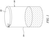
- FIG. 1 illustrates a reservoir 200 for storing a fluid.
- the reservoir 200 of the present disclosure is cylindrical in shape. However, the reservoir 200 may have any standard shape as per personal preference or application requirements.
- the reservoir 200 has an inner side 202 (shown in FIG. 2 ) and an outer side 204 disposed opposite to the inner side 202 .
- the texture of the inner side 202 of the reservoir 200 may be different from the texture of the outer side 204 of the reservoir 200 .
- the reservoir 200 is additionally covered by a cover 206 to prevent entry of any foreign elements that may contaminate the stored fluid when the fluid is not required for use for any application.
- the fluid may be stored in the inner side 202 of the reservoir 200 .
- the fluid may be any liquid, or semi liquid such as adhesives, lubricants, or other fluids. Further, the liquid may be a mixture of one or more liquids or semi liquids without limiting the scope of the present disclosure.
- the fluid stored in the reservoir 200 may be used or consumed for various applications thereby rendering the reservoir 200 empty.
- the re-usage of the reservoir 200 may be application based.
- the reservoir 200 may then be reused for storing a fluid, which may be different from the fluid previously stored in the reservoir 200 .
- the fluid previously stored in the reservoir 200 may leave behind a plurality of stains or sludge, which may be cleaned with a cleaning agent such as water and the like to prevent the fluid to be stored from contamination. However, the cleaning may not be sufficient to get rid of the stains or sludge entirely.
- an apparatus 100 is provided to prevent the fluid to be stored from contamination during the reuse of the reservoir 200 .
- An exemplary usage may be storage of rainwater.
- the apparatus 100 includes a receptacle 300 and the reservoir 200 .
- the receptacle 300 is retrofitted with the reservoir 200 .
- the receptacle 300 may be one or more of a sac, a bag, a pouch, or the like that may be expandable.
- the receptacle 300 may easily adapt to shape and size of the reservoir 200 to which the receptacle 300 may be retrofitted. Further, the receptacle 300 may shrink again after the use and may be easily held or stored until use for other applications.
- the receptacle 300 includes a body portion 310 adapted to store a fluid therein.
- the body portion 310 includes an outer surface 312 and an inner surface 314 disposed opposite to the outer surface 312 .
- the texture of the inner surface 314 of the receptacle 300 may be different from the texture of the outer surface 312 of the receptacle 300 .
- the body portion 310 defines a fluid receiving opening 316 to receive the fluid to be stored in contact with the inner surface 314 .
- the inner surface 314 may be composed of any material known in the art without limiting the scope of the present disclosure.
- a U-shaped circular bracket 500 may be used for coupling the periphery of the outer surface 312 of the receptacle 300 with the periphery of the reservoir 200 .
- a plurality of clips may be used for coupling the periphery of the outer surface 312 of the receptacle 300 with the periphery of the reservoir 200 .
- a plurality of fasteners such as, but not limited to, rivets may be used for coupling the periphery of the outer surface 312 of the receptacle 300 with the periphery of the reservoir 200 .
- the coupling may be obtained by any means known in the art without limiting the scope of the present disclosure.
- the outer surface 312 of the receptacle 300 is composed of a thermally sensitive material.
- the thermally sensitive material may respond to heat and may show different properties on exposure to heat.
- the thermally sensitive material may show adhesive properties upon application of heat.
- the outer surface 312 is further adapted to adhere to the inner side 202 of the reservoir 200 upon contact and maintain a constant adherence with the inner side 202 of the reservoir 200 (as shown in FIG. 3 ).
- the thermally sensitive material may show adhesive properties upon application of heat and the outer surface 312 of the receptacle 300 may adhere to the reservoir 200 upon application of heat.
- the apparatus 100 may know be readily used to store the fluid for various applications.
- a method 400 for retrofitting the receptacle 300 with the reservoir 200 is illustrated in FIG. 4 .
- the method 400 involves coupling a periphery of the outer surface 312 of the receptacle 300 with a periphery of the reservoir 200 .
- the U-shaped circular bracket 500 may be used for coupling the periphery of the outer surface 312 of the receptacle 300 with the periphery of the reservoir 200 (as shown in FIGS. 2 and 3 ).
- the method 400 involves providing a source of warm fluid (not shown).
- the source of warm fluid may be a source of hot air, or warm water or any other such fluid.
- the method 400 further includes feeding the fluid receiving opening 316 of the receptacle 300 with the warm fluid.
- the source of warm fluid may be a warm air blowing machine.
- the warm fluid may be provided by any means known in the art without limiting the scope of the present disclosure.
- the coupling at the step 402 between the periphery of the outer surface 312 of the receptacle 300 and the periphery of the reservoir 200 may provide secure grip as well as stability to the receptacle 300 when the fluid receiving opening 316 of the receptacle 300 is fed with the warm fluid.
- the U-shaped circular bracket 500 may also provide secure grip as well as stability to the receptacle 300 throughout the lifecycle of the receptacle 300 until which the receptacle 300 is retrofitted with the reservoir 200 .
- the feeding of the fluid receiving opening 316 of the receptacle 300 with the warm fluid ensures the receptacle 300 to be in an expanded state.
- the outer surface 312 of the receptacle 300 in the expanded state adheres to the inner side 202 of the reservoir 200 upon contact and maintains constant adherence with the inner side 202 of the reservoir 200 , thereby completing the retrofitting process of the receptacle 300 with the reservoir 200 (as shown in FIG. 3 ).
- the method 400 for retrofitting the receptacle 300 with the reservoir 200 is easy and cost-effective.
- the method 400 may be processed with limited requirement of any tools, technical knowledge, or special skills.
- the method 400 may also involve cleaning of the reservoir 200 before the step 402 .
- the reservoir 200 may be cleaned before retrofitting of the receptacle 300 with the reservoir 200 .
- the reservoir 200 may be casually cleaned or washed to wash away any large stain, sludge, or leftovers especially on the inner side 202 of the reservoir 200 .
- the substantially cleaned reservoir 200 may offer a planar surface or substantially planar surface on the inner side 202 for proper adherence of the receptacle 300 .
- the replacement of the receptacle 300 with a new receptacle (not shown) in case of change of the fluid stored in the reservoir 200 may be done by firstly removing the receptacle 300 .
- the receptacle 300 may be removed by uncoupling the periphery of the outer surface 312 of the receptacle 300 with the periphery of the reservoir 200 and then removing the body portion 310 of the receptacle 300 adhered to the inner side 202 of the reservoir 200 by any means known in the art without limiting the scope of the present disclosure.
- a new receptacle may be retrofitted with the reservoir 200 using the method 400 illustrated in FIG. 4 .
- the new receptacle may also be applied directly onto the existing receptacle 300 .
- the present disclosure provides the receptacle 300 which may be easily retrofitted with the reservoir 200 of any shape and size for storage of the fluid therein.
- the receptacle 300 due to the material characteristics maintains constant adherence with the inner side 202 of the reservoir 200 .
- the receptacle 300 does not slip inside the reservoir 200 due to the weight of the fluid poured therein for storage.
- the receptacle 300 prevents the fluid from contamination due to the stain, sludge, or leftovers of some other fluid previously stored in the reservoir 200 .
- the receptacle 300 eliminates the need for thorough cleaning of the reservoir 200 after the first use of the reservoir 200 .
- the receptacle 300 further eliminates the need for a liner, which is generally expensive to manufacture and install inside the reservoir 200 .
Landscapes
- Engineering & Computer Science (AREA)
- Mechanical Engineering (AREA)
- Manufacturing & Machinery (AREA)
- Details Of Rigid Or Semi-Rigid Containers (AREA)
Abstract
An apparatus (100) and a method (400) to facilitate a reuse of a reservoir (200) is provided. The apparatus (100) includes a receptacle (300) and the reservoir (200). The receptacle (300) is retrofitted with the reservoir (200). The receptacle (300) includes a body portion (310) adapted to store a fluid therein. The body portion (310) includes an outer surface (312) and an inner surface (314) disposed opposite to the outer surface (312). Further, the body portion (310) defines a fluid receiving opening (316) to receive the fluid to be stored in contact with the inner surface (314). The receptacle (300) is characterized in that the outer surface (312) is composed of a thermally sensitive material. The outer surface (312) is further adapted to adhere to an inner side (202) of the reservoir (200) upon contact and maintain a constant adherence with the inner side (202) of the reservoir (200).
Description
- The present disclosure relates to a reservoir. More specifically, the present disclosure relates to an apparatus and a method to facilitate reuse of the reservoir.
- A reservoir such as a steel drum or the like may be used as a means for storing a variety of fluids including liquids and semi liquids such as adhesives, lubricants, or other fluids. The fluid stored in the reservoir may be removed by first removing a top cover of the reservoir and then pouring or pumping out the stored fluid. The fluid once removed from the reservoir may leave stains or sludge on an inner surface of the reservoir.
- Many-a-times, it is desirable to use the reservoir for storing a fluid different from what was previously stored therein. One of the examples may be to reuse a reservoir previously used for oil or lubricants for industrial purpose for storing rainwater. To prevent contamination in the new fluid to be stored in the reservoir, a general practice may be to clean the reservoir or to provide a liner to cover the stain or sludge on the inner surface of the reservoir.
- An example of a reservoir with a removable liner is provided in
United States patent 2,912,136 (hereinafter referred to as '136 reference). The '136 reference provides a container for corrosive materials which utilizes standard containers such as fiber drums or ordinary steel barrels, which are normally used for transporting non-corrosive materials. The container is further provided with a corrosion-resistant liner, which may be easily inserted and removed. Another example of a reservoir with a removable liner is provided inUnited States patent 5,232,117 (hereinafter referred to as '117 reference). The ' 117 reference provides a metal drum having a detachable lining removable therefrom after a first use to allow for the reuse or recycling of the drum. - However, making of the liner is an expensive process and so is the cleaning process of the reservoir. Thus, there is a need of an apparatus or a method that may be inexpensive and may still facilitate reuse of the reservoir for storing the fluid, which may be different from what was previously stored therein.
- In view of the above, it is an objective of the present invention to solve or at least reduce the drawbacks discussed above. The objective is at least partially achieved by an apparatus. The apparatus includes a receptacle and a reservoir. The receptacle is retrofitted with the reservoir. The receptacle includes a body portion adapted to store a fluid therein. The body portion includes an outer surface and an inner surface disposed opposite to the outer surface. Further, the body portion defines a fluid receiving opening to receive the fluid to be stored in contact with the inner surface. The receptacle is characterized in that the outer surface is composed of a thermally sensitive material. The outer surface is further adapted to adhere to an inner side of the reservoir upon contact and maintain a constant adherence with the inner side of the reservoir.
- Thus, the present disclosure provides the receptacle which may be easily retrofitted with the reservoir of any shape and size for storage of the fluid therein. The receptacle maintains constant adherence with the inner side of the reservoir due to material characteristics of the receptacle. The receptacle does not slip inside the reservoir due to the weight of the fluid poured therein for storage. The receptacle prevents the fluid from contamination due to any stain, sludge, or leftovers of some other fluid previously stored in the reservoir. The receptacle eliminates the need for thorough cleaning of the reservoir after the first use of the reservoir, and therefore saves cleaning costs which may have otherwise incurred. The receptacle further eliminates the need for a liner or the like, which may be generally expensive to manufacture and install inside the reservoir.
- According to an embodiment of the present disclosure, the outer surface adheres to the reservoir upon application of heat. The material of the receptacle may illustrate adhesive properties upon application of heat. Thus, there may not be any need to externally apply an adhesive to the outer surface of the receptacle or the inner side of the reservoir.
- According to an embodiment of the present disclosure, the receptacle is expandable. The receptacle may easily adapt to the shape and size of the reservoir to which the receptacle may be retrofitted. Further, the receptacle may shrink again after the usage and may be easily held or stored.
- According to an embodiment of the present disclosure, a method for retrofitting the receptacle with the reservoir involves coupling a periphery of the outer surface of the receptacle with a periphery of the reservoir. The method further involves providing a source of warm fluid to feed the fluid receiving opening of the receptacle with the warm fluid so that the receptacle is ensured to be in an expanded state. Afterwards, the outer surface of the receptacle adheres to the inner side of the reservoir upon contact in the expanded state and maintains constant adherence with the inner side of the reservoir. The method is easy to execute and cost-effective as well. The method may be processed with limited requirement of any tools, technical knowledge, or special skills.
- According to an embodiment of the present disclosure, the reservoir is cleaned before retrofitting of the receptacle with the reservoir. The reservoir may be cleaned or washed to wash away any large stain, sludge, or leftovers especially on the inner side of the reservoir. The substantially cleaned reservoir may offer a planar surface or substantially planar surface on the inner side for proper adherence of the receptacle.
- According to an embodiment of the present disclosure, a U-shaped circular bracket is used for coupling the periphery of the outer surface of the receptacle with the periphery of the reservoir. The bracket may provide a secure grip as well as stability to the receptacle when the fluid receiving opening of the receptacle is fed with the warm fluid. However, the bracket may also provide the secure grip as well as stability to the receptacle throughout the lifecycle of the receptacle till the receptacle is retrofitted with the reservoir.
- Other features and aspects of this invention will be apparent from the following description and the accompanying drawings.
- The invention will be described in more detail with reference to the enclosed drawings, wherein:
-
FIG. 1 shows a perspective view of a reservoir for storing a fluid, in accordance with an aspect of the present disclosure; -
FIG. 2 shows a cross-sectional front view of a reservoir with a receptacle in an unexpanded state, in accordance with an aspect of the present disclosure; -
FIG. 3 shows a cross-sectional front view of a reservoir with a receptacle in an expanded state, in accordance with an aspect of the present disclosure; and -
FIG. 4 shows a flow chart highlighting the steps involved in retrofitting of a receptacle with a reservoir, in accordance with an aspect of the present disclosure. - The present invention will be described more fully hereinafter with reference to the accompanying drawings, in which example embodiments of the invention incorporating one or more aspects of the present invention are shown. This invention may, however, be embodied in many different forms and should not be construed as limited to the embodiments set forth herein; rather, these embodiments are provided so that this disclosure will be thorough and complete, and will fully convey the scope of the invention to those skilled in the art. For example, one or more aspects of the present invention may be utilized in other embodiments and even other types of structures and/or methods. In the drawings, like numbers refer to like elements.
- Certain terminology is used herein for convenience only and is not to be taken as a limitation on the invention. For example, "upper", "lower", "front", "rear", "side", "longitudinal", "lateral", "transverse", "upwards", "downwards", "forward", "backward", "sideward", "left," "right," "horizontal," "vertical," "upward", "inner", "outer", "inward", "outward", "top", "bottom", "higher", "above", "below", "central", "middle", "intermediate", "between", "end", "adjacent", "proximate", "near", "distal", "remote", "radial", "circumferential", or the like, merely describe the configuration shown in the Figures. Indeed, the components may be oriented in any direction and the terminology, therefore, should be understood as encompassing such variations unless specified otherwise.
-
FIG. 1 illustrates areservoir 200 for storing a fluid. Thereservoir 200 of the present disclosure is cylindrical in shape. However, thereservoir 200 may have any standard shape as per personal preference or application requirements. Thereservoir 200 has an inner side 202 (shown inFIG. 2 ) and anouter side 204 disposed opposite to theinner side 202. The texture of theinner side 202 of thereservoir 200 may be different from the texture of theouter side 204 of thereservoir 200. Thereservoir 200 is additionally covered by acover 206 to prevent entry of any foreign elements that may contaminate the stored fluid when the fluid is not required for use for any application. The fluid may be stored in theinner side 202 of thereservoir 200. The fluid may be any liquid, or semi liquid such as adhesives, lubricants, or other fluids. Further, the liquid may be a mixture of one or more liquids or semi liquids without limiting the scope of the present disclosure. - The fluid stored in the
reservoir 200 may be used or consumed for various applications thereby rendering thereservoir 200 empty. In some embodiments, the re-usage of thereservoir 200 may be application based. Thereservoir 200 may then be reused for storing a fluid, which may be different from the fluid previously stored in thereservoir 200. The fluid previously stored in thereservoir 200 may leave behind a plurality of stains or sludge, which may be cleaned with a cleaning agent such as water and the like to prevent the fluid to be stored from contamination. However, the cleaning may not be sufficient to get rid of the stains or sludge entirely. Hence, as illustrated inFIGS. 2 and3 , anapparatus 100 is provided to prevent the fluid to be stored from contamination during the reuse of thereservoir 200. An exemplary usage may be storage of rainwater. - The
apparatus 100 includes areceptacle 300 and thereservoir 200. Thereceptacle 300 is retrofitted with thereservoir 200. Thereceptacle 300 may be one or more of a sac, a bag, a pouch, or the like that may be expandable. Thereceptacle 300 may easily adapt to shape and size of thereservoir 200 to which thereceptacle 300 may be retrofitted. Further, thereceptacle 300 may shrink again after the use and may be easily held or stored until use for other applications. - The
receptacle 300 includes abody portion 310 adapted to store a fluid therein. Thebody portion 310 includes anouter surface 312 and aninner surface 314 disposed opposite to theouter surface 312. The texture of theinner surface 314 of thereceptacle 300 may be different from the texture of theouter surface 312 of thereceptacle 300. Further, thebody portion 310 defines afluid receiving opening 316 to receive the fluid to be stored in contact with theinner surface 314. Theinner surface 314 may be composed of any material known in the art without limiting the scope of the present disclosure. - As shown in
FIGS. 2 and3 , in some embodiments, a U-shapedcircular bracket 500 may be used for coupling the periphery of theouter surface 312 of thereceptacle 300 with the periphery of thereservoir 200. In some embodiments, a plurality of clips may be used for coupling the periphery of theouter surface 312 of thereceptacle 300 with the periphery of thereservoir 200. In some embodiments, a plurality of fasteners, such as, but not limited to, rivets may be used for coupling the periphery of theouter surface 312 of thereceptacle 300 with the periphery of thereservoir 200. However, the coupling may be obtained by any means known in the art without limiting the scope of the present disclosure. - The
outer surface 312 of thereceptacle 300 is composed of a thermally sensitive material. The thermally sensitive material may respond to heat and may show different properties on exposure to heat. In some embodiments, the thermally sensitive material may show adhesive properties upon application of heat. Theouter surface 312 is further adapted to adhere to theinner side 202 of thereservoir 200 upon contact and maintain a constant adherence with theinner side 202 of the reservoir 200 (as shown inFIG. 3 ). Thus, the thermally sensitive material may show adhesive properties upon application of heat and theouter surface 312 of thereceptacle 300 may adhere to thereservoir 200 upon application of heat. Hence, advantageously there is no need to externally apply an adhesive to theouter surface 312 of thereceptacle 300 or theinner side 202 of thereservoir 200, which is otherwise a clumsy task and may incur additional, unnecessary time, effort, and costs. Further, theapparatus 100 may know be readily used to store the fluid for various applications. - A
method 400 for retrofitting thereceptacle 300 with thereservoir 200 is illustrated inFIG. 4 . Atstep 402, themethod 400 involves coupling a periphery of theouter surface 312 of thereceptacle 300 with a periphery of thereservoir 200. In some embodiments, the U-shapedcircular bracket 500 may be used for coupling the periphery of theouter surface 312 of thereceptacle 300 with the periphery of the reservoir 200 (as shown inFIGS. 2 and3 ). - At
step 404, themethod 400 involves providing a source of warm fluid (not shown). The source of warm fluid may be a source of hot air, or warm water or any other such fluid. Atstep 406, themethod 400 further includes feeding thefluid receiving opening 316 of thereceptacle 300 with the warm fluid. In some embodiments, the source of warm fluid may be a warm air blowing machine. However, the warm fluid may be provided by any means known in the art without limiting the scope of the present disclosure. - Further, the coupling at the
step 402 between the periphery of theouter surface 312 of thereceptacle 300 and the periphery of thereservoir 200 may provide secure grip as well as stability to thereceptacle 300 when thefluid receiving opening 316 of thereceptacle 300 is fed with the warm fluid. However, the U-shapedcircular bracket 500 may also provide secure grip as well as stability to thereceptacle 300 throughout the lifecycle of thereceptacle 300 until which thereceptacle 300 is retrofitted with thereservoir 200. Further, the feeding of thefluid receiving opening 316 of thereceptacle 300 with the warm fluid ensures thereceptacle 300 to be in an expanded state. - Further, at
step 408, theouter surface 312 of thereceptacle 300 in the expanded state adheres to theinner side 202 of thereservoir 200 upon contact and maintains constant adherence with theinner side 202 of thereservoir 200, thereby completing the retrofitting process of thereceptacle 300 with the reservoir 200 (as shown inFIG. 3 ). Thus, themethod 400 for retrofitting thereceptacle 300 with thereservoir 200 is easy and cost-effective. Themethod 400 may be processed with limited requirement of any tools, technical knowledge, or special skills. - In some embodiments, the
method 400 may also involve cleaning of thereservoir 200 before thestep 402. Thereservoir 200 may be cleaned before retrofitting of thereceptacle 300 with thereservoir 200. Thereservoir 200 may be casually cleaned or washed to wash away any large stain, sludge, or leftovers especially on theinner side 202 of thereservoir 200. The substantially cleanedreservoir 200 may offer a planar surface or substantially planar surface on theinner side 202 for proper adherence of thereceptacle 300. - The replacement of the
receptacle 300 with a new receptacle (not shown) in case of change of the fluid stored in thereservoir 200 may be done by firstly removing thereceptacle 300. Thereceptacle 300 may be removed by uncoupling the periphery of theouter surface 312 of thereceptacle 300 with the periphery of thereservoir 200 and then removing thebody portion 310 of thereceptacle 300 adhered to theinner side 202 of thereservoir 200 by any means known in the art without limiting the scope of the present disclosure. Further, a new receptacle may be retrofitted with thereservoir 200 using themethod 400 illustrated inFIG. 4 . In some embodiments, the new receptacle may also be applied directly onto the existingreceptacle 300. - Thus, the present disclosure provides the
receptacle 300 which may be easily retrofitted with thereservoir 200 of any shape and size for storage of the fluid therein. Thereceptacle 300 due to the material characteristics maintains constant adherence with theinner side 202 of thereservoir 200. Thereceptacle 300 does not slip inside thereservoir 200 due to the weight of the fluid poured therein for storage. Thereceptacle 300 prevents the fluid from contamination due to the stain, sludge, or leftovers of some other fluid previously stored in thereservoir 200. Thereceptacle 300 eliminates the need for thorough cleaning of thereservoir 200 after the first use of thereservoir 200. Thereceptacle 300 further eliminates the need for a liner, which is generally expensive to manufacture and install inside thereservoir 200. - In the drawings and specification, there have been disclosed preferred embodiments and examples of the invention and, although specific terms are employed, they are used in a generic and descriptive sense only and not for the purpose of limitation of the scope of the invention being set forth in the following claims.
-
- 100
- Apparatus
- 200
- Reservoir
- 202
- Inner Side
- 204
- Outer Side
- 206
- Cover
- 300
- Receptacle
- 310
- Body Portion
- 312
- Outer Surface
- 314
- Inner Surface
- 316
- Fluid Receiving Opening
- 500
- U-Shaped Bracket
Claims (7)
- A receptacle (300) for retrofitting with a reservoir (200), the receptacle (300) comprising:a body portion (310) adapted to store a fluid therein, wherein the body portion (310) comprises:an outer surface (312); andan inner surface (314) disposed opposite to the outer surface (312),wherein the body portion (310) defines a fluid receiving opening (316) to receive the fluid to be stored in contact with the inner surface (314);characterized in that:the outer surface (312) is composed of a thermally sensitive material; andthe outer surface (312) is adapted to adhere to an inner side (202) of the reservoir (200) upon contact and maintain a constant adherence with the inner side (202) of the reservoir (200).
- The receptacle (300) of claim 1, wherein the outer surface (312) adheres to the reservoir (200) upon application of heat.
- The receptacle (300) of any of the preceding claims, wherein the receptacle (300) is expandable.
- A method (400) for retrofitting a receptacle (300) with a reservoir (200), the method (400) comprising:coupling a periphery of an outer surface (312) of the receptacle (300) with a periphery of the reservoir (200);providing a source of warm fluid;feeding a fluid receiving opening (316) of the receptacle (300) with the warm fluid so that the receptacle (300) is ensured to be in an expanded state;characterized in that:the outer surface (312) of the receptacle (300) in the expanded state adheres to an inner side (202) of the reservoir (200) upon contact and maintains a constant adherence with the inner side (202) of the reservoir (200).
- The method (400) of claim 4, wherein the outer surface (312) is composed of a thermally sensitive material.
- The method (400) of claim 4 and 5, wherein the reservoir (200) is cleaned before retrofitting of the receptacle (300) with the reservoir (200).
- The method (400) of any of the claims 4, 5 or 6, wherein a U-shaped circular bracket (500) is used for coupling the periphery of the outer surface (312) of the receptacle (300) with the periphery of the reservoir (200).
Priority Applications (1)
| Application Number | Priority Date | Filing Date | Title |
|---|---|---|---|
| EP21215271.4A EP4197934A1 (en) | 2021-12-16 | 2021-12-16 | A receptacle for retrofitting with a reservoir |
Applications Claiming Priority (1)
| Application Number | Priority Date | Filing Date | Title |
|---|---|---|---|
| EP21215271.4A EP4197934A1 (en) | 2021-12-16 | 2021-12-16 | A receptacle for retrofitting with a reservoir |
Publications (1)
| Publication Number | Publication Date |
|---|---|
| EP4197934A1 true EP4197934A1 (en) | 2023-06-21 |
Family
ID=79282968
Family Applications (1)
| Application Number | Title | Priority Date | Filing Date |
|---|---|---|---|
| EP21215271.4A Withdrawn EP4197934A1 (en) | 2021-12-16 | 2021-12-16 | A receptacle for retrofitting with a reservoir |
Country Status (1)
| Country | Link |
|---|---|
| EP (1) | EP4197934A1 (en) |
Citations (6)
| Publication number | Priority date | Publication date | Assignee | Title |
|---|---|---|---|---|
| US2314338A (en) * | 1940-11-08 | 1943-03-23 | Sefton Fibre Can Company | Container |
| US2912136A (en) | 1956-03-12 | 1959-11-10 | Automotive Rubber Co Inc | Container for corrosive materials |
| US5083995A (en) * | 1990-05-18 | 1992-01-28 | Sonoco Products Company | Method of forming a protective chime overlay |
| DE4117856A1 (en) * | 1991-05-31 | 1992-12-03 | Gefinex Gmbh | METHOD FOR INTERCHANGEABLE INTERNAL LINING OF BUCKETS WITH PLASTIC |
| US5232117A (en) | 1992-04-13 | 1993-08-03 | Greif Bros. Corporation | Reusable metal drum |
| US20190217990A1 (en) * | 2016-09-23 | 2019-07-18 | Mauser-Werke Gmbh | Closed-head drum with liner, and method for producing the same |
-
2021
- 2021-12-16 EP EP21215271.4A patent/EP4197934A1/en not_active Withdrawn
Patent Citations (6)
| Publication number | Priority date | Publication date | Assignee | Title |
|---|---|---|---|---|
| US2314338A (en) * | 1940-11-08 | 1943-03-23 | Sefton Fibre Can Company | Container |
| US2912136A (en) | 1956-03-12 | 1959-11-10 | Automotive Rubber Co Inc | Container for corrosive materials |
| US5083995A (en) * | 1990-05-18 | 1992-01-28 | Sonoco Products Company | Method of forming a protective chime overlay |
| DE4117856A1 (en) * | 1991-05-31 | 1992-12-03 | Gefinex Gmbh | METHOD FOR INTERCHANGEABLE INTERNAL LINING OF BUCKETS WITH PLASTIC |
| US5232117A (en) | 1992-04-13 | 1993-08-03 | Greif Bros. Corporation | Reusable metal drum |
| US20190217990A1 (en) * | 2016-09-23 | 2019-07-18 | Mauser-Werke Gmbh | Closed-head drum with liner, and method for producing the same |
Similar Documents
| Publication | Publication Date | Title |
|---|---|---|
| US5169019A (en) | Internally lined bung-type container | |
| US5627150A (en) | Paperboard container for solid block detergents | |
| US6199718B1 (en) | Paint bucket with integral grate | |
| US5217138A (en) | Liquid transport drum with removable liner | |
| US4347948A (en) | Container for filling in liquid | |
| JP2001508698A (en) | Liquid spray device and disposable storage container and liner suitable for use with the device | |
| CZ153094A3 (en) | Pallet container and process for producing thereof | |
| US4251155A (en) | Cleaning arrangement in an electrophotographic copying machine | |
| JP2011502768A (en) | Solvent recycler | |
| AU640045B2 (en) | Liquid transport drum with removable liner | |
| US5232117A (en) | Reusable metal drum | |
| US2912136A (en) | Container for corrosive materials | |
| US9174776B1 (en) | Methods and devices for improved materials storage | |
| US5255492A (en) | Detachable cover and drum liner for storage and transport of controlled materials | |
| US5503701A (en) | Method for providing recyclable steel drum for hot flow products | |
| JP6719131B2 (en) | Pail can with concave bead and method of manufacturing pail can | |
| JP5577578B2 (en) | Method for supplying hot melt adhesive contained in a hot melt adhesive container | |
| US5636670A (en) | Oil/liquid recovery system | |
| JP3035568B2 (en) | Tank with inner lid for viscous materials such as ink | |
| JP2916679B2 (en) | Tank with inner lid | |
| US20190077560A1 (en) | Container and support frame system for bulk products | |
| US9963285B1 (en) | Flexible bucket-type disposable container | |
| JP3084202U (en) | Refill stand for various refill liquid bags | |
| JP4587973B2 (en) | How to recycle paint containers | |
| JPH1129128A (en) | Container |
Legal Events
| Date | Code | Title | Description |
|---|---|---|---|
| PUAI | Public reference made under article 153(3) epc to a published international application that has entered the european phase |
Free format text: ORIGINAL CODE: 0009012 |
|
| STAA | Information on the status of an ep patent application or granted ep patent |
Free format text: STATUS: THE APPLICATION HAS BEEN PUBLISHED |
|
| AK | Designated contracting states |
Kind code of ref document: A1 Designated state(s): AL AT BE BG CH CY CZ DE DK EE ES FI FR GB GR HR HU IE IS IT LI LT LU LV MC MK MT NL NO PL PT RO RS SE SI SK SM TR |
|
| STAA | Information on the status of an ep patent application or granted ep patent |
Free format text: STATUS: THE APPLICATION IS DEEMED TO BE WITHDRAWN |
|
| 18D | Application deemed to be withdrawn |
Effective date: 20231222 |