EP4197916A1 - Magnetically controlled fluid drain valve for aircraft exterior light unit - Google Patents
Magnetically controlled fluid drain valve for aircraft exterior light unit Download PDFInfo
- Publication number
- EP4197916A1 EP4197916A1 EP22211371.4A EP22211371A EP4197916A1 EP 4197916 A1 EP4197916 A1 EP 4197916A1 EP 22211371 A EP22211371 A EP 22211371A EP 4197916 A1 EP4197916 A1 EP 4197916A1
- Authority
- EP
- European Patent Office
- Prior art keywords
- poppet
- valve
- magnet
- various embodiments
- magnetic
- Prior art date
- Legal status (The legal status is an assumption and is not a legal conclusion. Google has not performed a legal analysis and makes no representation as to the accuracy of the status listed.)
- Granted
Links
Images




Classifications
-
- B—PERFORMING OPERATIONS; TRANSPORTING
- B64—AIRCRAFT; AVIATION; COSMONAUTICS
- B64D—EQUIPMENT FOR FITTING IN OR TO AIRCRAFT; FLIGHT SUITS; PARACHUTES; ARRANGEMENT OR MOUNTING OF POWER PLANTS OR PROPULSION TRANSMISSIONS IN AIRCRAFT
- B64D47/00—Equipment not otherwise provided for
- B64D47/02—Arrangements or adaptations of signal or lighting devices
-
- F—MECHANICAL ENGINEERING; LIGHTING; HEATING; WEAPONS; BLASTING
- F16—ENGINEERING ELEMENTS AND UNITS; GENERAL MEASURES FOR PRODUCING AND MAINTAINING EFFECTIVE FUNCTIONING OF MACHINES OR INSTALLATIONS; THERMAL INSULATION IN GENERAL
- F16K—VALVES; TAPS; COCKS; ACTUATING-FLOATS; DEVICES FOR VENTING OR AERATING
- F16K15/00—Check valves
- F16K15/02—Check valves with guided rigid valve members
- F16K15/021—Check valves with guided rigid valve members the valve member being a movable body around which the medium flows when the valve is open
- F16K15/023—Check valves with guided rigid valve members the valve member being a movable body around which the medium flows when the valve is open the valve member consisting only of a predominantly disc-shaped flat element
-
- F—MECHANICAL ENGINEERING; LIGHTING; HEATING; WEAPONS; BLASTING
- F16—ENGINEERING ELEMENTS AND UNITS; GENERAL MEASURES FOR PRODUCING AND MAINTAINING EFFECTIVE FUNCTIONING OF MACHINES OR INSTALLATIONS; THERMAL INSULATION IN GENERAL
- F16K—VALVES; TAPS; COCKS; ACTUATING-FLOATS; DEVICES FOR VENTING OR AERATING
- F16K17/00—Safety valves; Equalising valves, e.g. pressure relief valves
- F16K17/02—Safety valves; Equalising valves, e.g. pressure relief valves opening on surplus pressure on one side; closing on insufficient pressure on one side
- F16K17/04—Safety valves; Equalising valves, e.g. pressure relief valves opening on surplus pressure on one side; closing on insufficient pressure on one side spring-loaded
- F16K17/06—Safety valves; Equalising valves, e.g. pressure relief valves opening on surplus pressure on one side; closing on insufficient pressure on one side spring-loaded with special arrangements for adjusting the opening pressure
-
- F—MECHANICAL ENGINEERING; LIGHTING; HEATING; WEAPONS; BLASTING
- F16—ENGINEERING ELEMENTS AND UNITS; GENERAL MEASURES FOR PRODUCING AND MAINTAINING EFFECTIVE FUNCTIONING OF MACHINES OR INSTALLATIONS; THERMAL INSULATION IN GENERAL
- F16K—VALVES; TAPS; COCKS; ACTUATING-FLOATS; DEVICES FOR VENTING OR AERATING
- F16K31/00—Actuating devices; Operating means; Releasing devices
- F16K31/02—Actuating devices; Operating means; Releasing devices electric; magnetic
- F16K31/06—Actuating devices; Operating means; Releasing devices electric; magnetic using a magnet, e.g. diaphragm valves, cutting off by means of a liquid
- F16K31/08—Actuating devices; Operating means; Releasing devices electric; magnetic using a magnet, e.g. diaphragm valves, cutting off by means of a liquid using a permanent magnet
- F16K31/084—Actuating devices; Operating means; Releasing devices electric; magnetic using a magnet, e.g. diaphragm valves, cutting off by means of a liquid using a permanent magnet the magnet being used only as a holding element to maintain the valve in a specific position, e.g. check valves
Definitions
- the present disclosure relates to aircraft lighting systems, and, more specifically, to aircraft exterior lamps and lighting systems.
- Exterior lighting on an aircraft enhances safety on the ground, during taxiing, and in-flight. Exterior systems often include anti-collision lighting, floor and spotlights, navigation lights and beacons, and emergency lights. These lights, which can be found on the upper and lower fuselage, tail, and wings, are subjected to intense environmental conditions, such as high winds and storms, as well as vast temperature and pressure changes during aircraft climb and descent. These conditions can damage the lighting systems. For example, since the external ambient air pressure varies with flight altitude, the light units are usually vented to avoid excessive overpressure or loss of pressure formed during flight ascent and descent periods. In exchanging air between the interior of an exterior light unit and the environment, water vapor in the air may flow into the exterior light unit and may eventually condense within the unit as the temperature changes. Liquid water build-up may deteriorate light unit functionality, threating operational safety of the entire aircraft.
- the aircraft light unit may comprise a lighting housing and a valve.
- the valve may comprise an inlet fitting body, an inner body, and a permanent magnet.
- the inlet fitting body may have a non-magnetic collar portion and a magnetic shoulder portion.
- the collar portion may at least partially define a lighting cavity and couple to the lighting housing at the lighting cavity.
- the collar portion may be downstream of the lighting housing.
- the shoulder portion may comprise an inner surface at least partially defining an air gap.
- the inner body may have a poppet disposed between the inner surface of the shoulder portion and a seat.
- the seat may be configured to support the poppet.
- the inner body may define a plurality of cavities. The plurality of cavities may be configured to permit water to drain from the upstream lighting housing.
- the poppet may further comprise a poppet stem.
- the poppet stem may define a channel.
- the channel may be configured to permit at least one of air and water vapor to pass therethrough.
- the poppet may further comprise a membrane.
- the membrane may be a semi-permeable membrane.
- the membrane may be configured to overlay the poppet stem defining the channel.
- the membrane may be configured to permit at least one of air and water vapor to pass therethrough.
- the membrane may be further configured to be impermeable to liquid water.
- the permanent magnet may be disposed between the inner body and an outer body of the valve.
- the magnet may further comprise an inner cylindrical face having a north pole and an outer cylindrical face having a south pole.
- the magnet may be radially polarized between the inner cylindrical face and the outer cylindrical face.
- the magnet may comprise a plurality of annular segments. The plurality of annular segments may define a plurality of recesses. Each recess may extend between the inner cylindrical face and the outer cylindrical face of the magnet.
- the magnet may be a continuous, annular magnet.
- the magnet may be configured to induce a magnetic flux circuit.
- the magnetic flux circuit may comprise a plurality of closed loop paths containing a magnetic flux.
- the magnetic flux may originate from the inner cylindrical face of the magnet.
- the magnetic flux may flow through the inner body and up the poppet.
- the magnetic flux may traverse the air gap into the magnetic shoulder portion of the inlet fitting body.
- the magnetic flux may flow down the inner body and into the outer body.
- the magnetic flux may terminate at the outer cylindrical face of the magnet.
- valve for an exterior aircraft light unit is also disclosed herein.
- the valve may include an inlet fitting body, an inner body, and a permanent magnet.
- the inner body may include a poppet, a polymer seal, and a semi-permeable membrane.
- the inlet fitting body may have a non-magnetic collar portion and a magnetic shoulder portion.
- the collar portion may at least partially define a lighting cavity.
- the shoulder portion may comprise an inner surface at least partially defining an air gap.
- the poppet may be disposed between the inner surface of the shoulder portion and a seat.
- the seat may be configured to support the poppet.
- the poppet may further comprise a poppet stem.
- the poppet stem may define a channel. In various embodiments, the channel may be configured to permit at least one of air and water vapor to pass therethrough.
- the polymer seal may be retained within an annular groove of the poppet. In various embodiments, the polymer seal may be configured to couple the poppet to the inner surface of the shoulder portion of the inlet fitting body. In various embodiments, polymer seal may be an O-ring. In various embodiments, the polymer seal may be configured to retain the poppet to the shoulder portion in a seated position.
- the semi-permeable membrane may be configured to overlay the poppet stem defining the channel. In various embodiments, the semi-permeable membrane may be configured to permit at least one of air and water vapor to pass into the channel. In various embodiments, the semi-permeable membrane may be further configured to be impermeable to liquid water. In various embodiments, the liquid water may be configured to accumulate along the membrane.
- the permanent magnet may be disposed between the inner body and an outer body of the valve.
- the magnet may be comprised of an inner cylindrical face having a north pole and an outer cylindrical face having a south pole.
- the magnet of the valve may be configured to induce a magnetic flux circuit.
- the magnetic flux circuit may comprise a plurality of closed loop paths containing a magnetic flux. The magnetic flux may originate from the inner cylindrical face of the magnet.
- the magnetic flux may flow through the inner body and up the poppet.
- the magnetic flux may traverse the air gap into the magnetic shoulder portion of the inlet fitting body.
- the magnetic flux may flow down the inner body and into the outer body.
- the magnetic flux may terminate at the outer cylindrical face of the magnet.
- the magnetic flux traversing across the air gap may develop a magnetic force across the air gap.
- the magnetic force across the air gap may be configured to attract the poppet to the inner surface of the shoulder portion.
- the magnetic force may be configured to close the valve.
- the poppet may be configured to move out of the seated position and open the valve when the magnetic force across the air gap is exceeded by a pressure force of the impermeable liquid water acting on the poppet.
- the magnetic force across the air gap may decrease as the valve opens.
- the inner body may define a plurality of cavities.
- the plurality of cavities may be configured to permit water to drain out of the valve as the valve opens.
- the pressure force of the impermeable liquid water accumulated along the semi-permeable membrane may decrease as the water drains out the valve.
- the magnetic force across the air gap may be configured to increase as the pressure force of the liquid water within the valve decreases. In various embodiments, the increasing magnetic force across the air gap may shift the poppet back into a seated position.
- a method of assembling a valve for an aircraft light unit is also disclosed herein.
- the method may comprise assembling a poppet.
- the poppet may comprise a poppet stem defining a channel.
- the channel may be configured to permit at least one of air and water vapor to pass therethrough.
- the poppet may further comprise a planar face defining an annular groove.
- assembling the poppet may further comprise, installing a polymer seal within the annular groove.
- the polymer seal may be an O-ring.
- assembling the poppet may further comprise overlaying the channel with a semi-permeable membrane.
- the semi-permeable membrane may be configured to permit at least one of air and water vapor to pass into the channel.
- the semi-permeable membrane may be further configured to be impermeable to liquid water. The liquid water may accumulate along the membrane.
- the method of assembling the valve may further comprise placing a seat within an inner body of the valve.
- the method may further comprise disposing the poppet onto the seat within the inner body.
- the seat may be configured to support the poppet.
- the inner body may be configured to house the poppet and the seat.
- the method may further comprise setting the inner body within an outer body.
- the outer body may be configured to ring the inner body.
- setting the inner body within the outer body may define a recess between the inner body and the outer body.
- the method of assembling the valve may further comprise disposing a permanent magnet within the recess between the inner body and the outer body.
- the magnet may further comprise an inner cylindrical face having a north pole and an outer cylindrical face having a south pole.
- the method of assembling the valve may further comprise enclosing the valve with an inlet fitting body.
- the inlet fitting body may be configured to cover the inner body, the magnet, and the outer body.
- the inlet fitting body may comprise a shoulder portion and a collar portion.
- the collar portion may at least partially define a lighting cavity.
- the collar portion may be configured to couple to a lighting housing of a lighting unit at the lighting cavity.
- an aircraft 100 in accordance with various embodiments may comprise aircraft systems, for example, one or more landing gear such as landing gear 12, which may generally support aircraft 100 when aircraft is not flying, allowing aircraft 100 to taxi, take off, and land without damage.
- Aircraft 100 may include one or more exterior lamps 14, or lighting units, such as, for example, landing lights 120, taxi lights 122, and navigation lights 126.
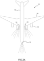
- FIGS. 2A and 2B the aircraft 100 is illustrated according to various embodiments.
- the aircraft 100 includes a fuselage 102, a pair of wings 104, and a pair of engines 106 for each wing 104.
- the aircraft 100 include landing lights 120, taxi lights 122, and runway turnoff lights 124.
- Aircraft 100 may include any number of other exterior lamps 14 such as logo lights, engine scan lights, anti-collision lights, strobe lights, beacon lights, cargo compartment lights, obstruction lights, landing gear lights, and/or the like.
- the exterior lamps 14 may comprise a variety of pressure release mechanisms, for example, one or more pressure release valves. As fluid in the exterior lamp is collected in the ambient air, the valves may release the fluid to prevent damage to the exterior lamp.
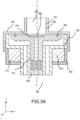
- FIGS. 3A-3C illustrate cross-sections of a magnetically controlled fluid drain valve 300.
- the valve 300 may include an inlet fitting body 301, an inner body 322, an outer body 304, and a permanent magnet 312.
- the inlet fitting body 301 may include a collar portion 305 and a shoulder portion 303.
- the collar portion 305 may at least partially define a lighting cavity 307.
- the collar portion 305 may be configured to assemble at the lighting cavity 307 to a corresponding structure of the lighting housing.
- gravity may be in the negative y direction along the y-y axis.
- liquid water, water vapor, and air may flow from the lighting housing through the collar portion 305 in the negative y direction.
- the collar portion 305 and the shoulder portion 303 may be comprised of different materials.
- the collar portion 305 may be comprised of a non-magnetic material, and the shoulder portion 303 may comprise a magnetic material.
- the shoulder portion 303 may comprise an inner surface at least partially defining an air gap 309.
- the inner body 322 may include a poppet 310.
- the poppet 310 may be disposed between the inner surface of the shoulder portion 303 and a seat 308.
- the seat 308 may be configured to support the poppet 310.
- the seat 308 may be a spring.
- the poppet 310 may be configured to sit flush against the inner surface of the shoulder portion 303.
- the poppet 310 may have an annular groove configured to retain a polymer seal 302.
- the polymer seal 302 may be configured to couple the poppet 310 to the inner surface of the shoulder portion 303 of the inlet fitting body 301.
- the inner surface of the shoulder portion 303 may be serrated to improve coupling of the polymer seal 302 to the inner surface of the shoulder portion 303.
- the polymer seal 302 may be configured to retain the poppet 310 to the shoulder portion 303 in a seated position.
- the polymer seal 302 may be an O-ring, or any substantially ring-like shape. As shown in FIG. 3A , the valve 300 may be in a closed position, and the poppet 310 in a seated position, when the polymer seal 302 is coupled to the inner surface of the shoulder portion 303.
- the polymer seal 302 coupled to the inner surface of the shoulder portion 303 may prevent the ingress of fluid into the valve's 300 inner body 322.
- the poppet 310 may further comprise a poppet stem defining a channel 316.
- the channel 316 may be configured to permit at least one of air and water vapor to pass therethrough. In doing so, the poppet 310 may be configured to control the flow of gas exchanged between the lighting unit and the external environment.
- the poppet 310 may include a membrane 314.
- the membrane 314 may be configured to overlay the poppet stem defining the channel 316. In various embodiments, the membrane 314 may be disposed within a diameter of the polymer seal 302.
- the membrane 314 may be semi-permeable and may be configured to permit air, water vapor, and other gases, to pass therethrough, exchanging gases with the external environment via the channel. It may be especially advantageous to allow water vapor to be exchanged to prevent its condensation into liquid water within the valve 300 and/or lighting housing. Some water vapor may condense and accumulate as liquid water along the semi-permeable membrane 314.
- the membrane 314 may be impermeable to liquid water.
- the membrane 314 may comprise expanded polytetrafluoroethylene.
- a magnetically controlled fluid drain valve may further comprise a permanent magnet 312.
- the magnet 312 may be disposed between the inner body 322 and the outer body 304.
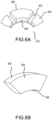
- the magnet 612 may further comprise a plurality of annular segments 604.
- the plurality of annular segments 604 may define a plurality of recesses 602.
- the magnet 612 may further comprise an inner cylindrical face 606 having a north pole and an outer cylindrical face 600 having a south pole.
- the magnet may be radially polarized between the inner cylindrical face 606 and the outer cylindrical face 600, keeping the north pole and the south pole in the cylindrical faces.
- each recess 602 may extend between the inner cylindrical face 606 and the outer cylindrical face 600 of the magnet 612. To maintain optimal magnetic strength, it may be desirable to space the segments closer together, reducing recess width.
- the magnet 612 may comprise at least one recess or no recess at all. In various embodiments, the magnet 612 may be a continuous, annular magnet.
- the magnet 312 may be configured to induce a magnetic flux circuit 318.
- the magnetic flux circuit 318 may comprise a plurality of closed loop paths containing a magnetic flux.
- the magnetic flux circuit 318 may originate from the inner cylindrical face 606 of the magnet 612, flow through the inner body 322 and up the poppet 310, traverse the air gap into the magnetic shoulder portion 303 of the inlet fitting body, flow down the inner body 322 and into the outer body 304, and terminate at the outer cylindrical face 600 of the magnet 312.
- the inner body 322, the outer body 304, the poppet 310, and the shoulder portion 303 of the inlet fitting body 301 may be comprised of magnetically permeable materials, such as, for example, soft iron, iron, cobalt, steel, chromium steel, ferro-magnetic stainless steel, and the like.
- the collar portion 305 of the inlet fitting body 301 may be comprised of non-magnetic materials, such as, for example, austenitic chromium-nickel stainless steel and low carbon versions thereof, and the like.
- the magnet 312 may be comprised of, for example, samarium cobalt, or any other suitable magnet material.
- the polymer seal 302 may be comprised of soft polymer materials, such as, for example, polytetrafluoroethylene (PTFE), tetrafluoroethylene, and the like.
- the magnetic flux circuit 318 may be fixed by the magnet design and the reluctance or resistance in the flux path.
- the primary reluctance is due to the air gap length, or the space defined by the inner surface of the shoulder portion 303 and the poppet 310.
- the magnetic force across the air gap may be configured to attract the poppet 310 to the inner surface of the shoulder portion 303, closing the valve 300. This magnetic force may close the valve 300 and may be configured to induce a compressive sealing stress of the polymer seal 302 against the inner face of the shoulder portion 303, keeping the valve 300 in closed position and the poppet 310 in a seated position.
- magnetic force generated by the magnetic flux circuit 318 is not the only force acting on the poppet 310.
- the pressure of the liquid water accumulating along and trapped by the semi-permeable membrane 314 may be influenced by the pressure differences between the light unit and the external environment.
- the light unit pressure in response to the pressure force of the light unit exceeding the magnetic force, the light unit pressure may act on the trapped liquid along the poppet 310, pushing the poppet 310 in the negative y direction along the y-y axis onto the seat 308 and out the seated position. This increases the air gap defined by the shoulder portion 303 and decouples the polymer seal 302 from the inner face of the shoulder portion 303.
- FIG. 5B illustrates a cross-section along the x-x axis of FIG. 5A .
- the inner body 522 may define a plurality of cavities 520.
- the cavities 520 may be configured to permit liquid water to drain from the upstream lighting housing.
- 306 is later referred to as cavities.
- the liquid water may be blocked from entering the cavities by the polymer seal 302. As the polymer seal 302 decouples from the inner face of the shoulder portion 303, the liquid water may exit the valve 300 via the cavities 306.
- the semi-permeable membrane 314 overlaying the channel 316 remains impermeable to liquid water.
- the cavities 306 may act as a primary liquid water drain, while the channel remains an air/water vapor exchange.
- the polymer seal 302 may prevent secondary leakage into the cavities 306.
- the poppet 310 may be transmitted linearly within the inner body 322 in response to a force acting upon it at the inner surface air gap.
- This force may be, for example, the pressure of the liquid water acting on the poppet or the magnetic force attracting the poppet to the inner surface of the shoulder portion.
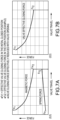
- FIGS. 7A and 7B illustrate a particular benefit of the magnetically controlled fluid drain valve shown in previous figured.
- the magnetic force is proportional to the pole face area and the square of the magnetic flux density available across the air gap.
- FIG. 7B as the air gap defined by the shoulder portion 303 increases, pushing the valve 300 open from the closed position, the magnetic force across the air gap decreases.
- the pressure within the lighting unit may equalize with that of the external environment, reducing the pressure force within the lighting unit and valve 300 relative to that of the magnetic force generated by the magnetic flux circuit 318.
- the magnetic force generated by the magnetic flux circuit 318 traversing across the air gap attracts the poppet 310 back to the inner face of the shoulder portion 303, reducing the size of the air gap.
- the magnetic force continues to increase as the air gap decreases, urging the polymer seal 302 into the inner face of the shoulder portion 303 and inducing compressive stress once more.
- a seat 308, or spring that may exert de minimus force onto the poppet 310, especially as the poppet 310 moves in the negative y direction along the y-y axis within the inner body 322 as the valve 300 opens. If the seat force acting on the poppet 310 as the valve opens were to exceed the minimum magnetic force, then the seat 308, rather than the magnet 312 would determine when the valve closes. This may be less desirable, since the seat 308 may force the valve 300 closed before all the liquid water is drained. For example, in a typical spring-based valve, as the valve opens, a spring with a high spring rate is more likely to close the valve shut before the water drains. The spring constant of a given coil spring, rather than the pressure within the light unit, would determine the timing of valve closure.
- valve 300 may stay open longer as the pressure between the lighting unit and the external environment equalizes, increasing the likelihood that the liquid water is fully drained.
- the magnetic force decreases, ensuring that less force will oppose the poppet 310 as the valve opens, and effectively creating a negative spring rate to keep the valve 300 open longer.
- the relationship between the lighting unit pressure and the magnetic force determines the timing of valve actuation (i.e., opening and closing), rather than any force exerted by the seat 308.
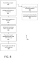
- FIG. 8 illustrates a method 800 of assembling the valve 300.
- the method 800 may comprise assembling 801 a poppet 310.
- the poppet 310 may comprise a poppet stem defining a channel 316.
- the channel 316 may be configured to permit at least one of air and water vapor to pass therethrough.
- the poppet 310 may further comprise a planar face 325 defining an annular groove.
- assembling 801 the poppet 310 may further comprise installing 802 a polymer seal 302 within the annular groove.
- the polymer seal 302 may be an O-ring.
- assembling 801 the poppet 310 may further comprise overlaying 803 the channel 316 with a semi-permeable membrane 314.
- the semi-permeable membrane 314 may be configured to permit at least one of air and water vapor to pass into the channel 316.
- the semi-permeable membrane 314 may be further configured to be impermeable to liquid water. The liquid water may accumulate along the membrane 314.
- the method of assembling 800 the valve 300 may further comprise placing 804 a seat 308 within an inner body 322 of the valve 300.
- the method 800 may further comprise disposing 805 the poppet 310 onto the seat 308 within the inner body 322.
- the seat 308 may be configured to support the poppet 310.
- the inner body 322 may be configured to house the poppet 310 and the seat 308.
- the method 800 may further comprise setting 806 the inner body 322 within an outer body 304.
- the outer body 304 may be configured to ring the inner body 322.
- setting 806 the inner body 322 within the outer body 304 may define a recess between the inner body 322 and the outer body 304.
- the method of assembling 800 the valve may further comprise disposing 807 a permanent magnet 312 within the recess between the inner body 322 and the outer body 304.
- the magnet 312 may further comprise an inner cylindrical face 606 having a north pole and an outer cylindrical face 600 having a south pole.
- the method of assembling 800 the valve 300 may further comprise enclosing 808 the valve 300 with an inlet fitting body 301.
- the inlet fitting body 301 may be configured to cover the inner body 322, the magnet 312, and the outer body 304.
- the inlet fitting body 301 may comprise a shoulder portion 303 and a collar portion 305.
- the shoulder portion 303 may comprise an inner surface that at least partially defines an air gap 309.
- the collar portion 305 may at least partially define a lighting cavity 307.
- the collar portion may be configured to couple to a lighting housing of a lighting unit at the lighting cavity.
- references to "various embodiments”, “one embodiment”, “an embodiment”, “an example embodiment”, etc. indicate that the embodiment described may include a particular feature, structure, or characteristic, but every embodiment may not necessarily include the particular feature, structure, or characteristic. Moreover, such phrases are not necessarily referring to the same embodiment. Further, when a particular feature, structure, or characteristic is described in connection with an embodiment, it is submitted that it is within the knowledge of one skilled in the art to affect such feature, structure, or characteristic in connection with other embodiments whether or not explicitly described. After reading the description, it will be apparent to one skilled in the relevant art(s) how to implement the disclosure in alternative embodiments.
Landscapes
- Engineering & Computer Science (AREA)
- General Engineering & Computer Science (AREA)
- Mechanical Engineering (AREA)
- Aviation & Aerospace Engineering (AREA)
- Arrangement Of Elements, Cooling, Sealing, Or The Like Of Lighting Devices (AREA)
- Magnetically Actuated Valves (AREA)
Abstract
Description
- The present disclosure relates to aircraft lighting systems, and, more specifically, to aircraft exterior lamps and lighting systems.
- Exterior lighting on an aircraft enhances safety on the ground, during taxiing, and in-flight. Exterior systems often include anti-collision lighting, floor and spotlights, navigation lights and beacons, and emergency lights. These lights, which can be found on the upper and lower fuselage, tail, and wings, are subjected to intense environmental conditions, such as high winds and storms, as well as vast temperature and pressure changes during aircraft climb and descent. These conditions can damage the lighting systems. For example, since the external ambient air pressure varies with flight altitude, the light units are usually vented to avoid excessive overpressure or loss of pressure formed during flight ascent and descent periods. In exchanging air between the interior of an exterior light unit and the environment, water vapor in the air may flow into the exterior light unit and may eventually condense within the unit as the temperature changes. Liquid water build-up may deteriorate light unit functionality, threating operational safety of the entire aircraft.
- An aircraft light unit is disclosed herein. In various embodiments, the aircraft light unit may comprise a lighting housing and a valve. In various embodiments, the valve may comprise an inlet fitting body, an inner body, and a permanent magnet. In various embodiments, the inlet fitting body may have a non-magnetic collar portion and a magnetic shoulder portion. In various embodiments, the collar portion may at least partially define a lighting cavity and couple to the lighting housing at the lighting cavity. In various embodiments, the collar portion may be downstream of the lighting housing. In various embodiments, the shoulder portion may comprise an inner surface at least partially defining an air gap.
- In various embodiments, the inner body may have a poppet disposed between the inner surface of the shoulder portion and a seat. In various embodiments, the seat may be configured to support the poppet. In various embodiments, the inner body may define a plurality of cavities. The plurality of cavities may be configured to permit water to drain from the upstream lighting housing.
- In various embodiments, the poppet may further comprise a poppet stem. In various embodiments, the poppet stem may define a channel. In various embodiments, the channel may be configured to permit at least one of air and water vapor to pass therethrough. In various embodiments, the poppet may further comprise a membrane. The membrane may be a semi-permeable membrane. In various embodiments, the membrane may be configured to overlay the poppet stem defining the channel. In various embodiments, the membrane may be configured to permit at least one of air and water vapor to pass therethrough. In various embodiments, the membrane may be further configured to be impermeable to liquid water.
- In various embodiments, the permanent magnet may be disposed between the inner body and an outer body of the valve. In various embodiments, the magnet may further comprise an inner cylindrical face having a north pole and an outer cylindrical face having a south pole. In various embodiments, the magnet may be radially polarized between the inner cylindrical face and the outer cylindrical face. In various embodiments, the magnet may comprise a plurality of annular segments. The plurality of annular segments may define a plurality of recesses. Each recess may extend between the inner cylindrical face and the outer cylindrical face of the magnet. In various embodiments, the magnet may be a continuous, annular magnet.
- In various embodiments, the magnet may be configured to induce a magnetic flux circuit. In various embodiments, the magnetic flux circuit may comprise a plurality of closed loop paths containing a magnetic flux. The magnetic flux may originate from the inner cylindrical face of the magnet. In various embodiments, the magnetic flux may flow through the inner body and up the poppet. In various embodiments, the magnetic flux may traverse the air gap into the magnetic shoulder portion of the inlet fitting body. In various embodiments, the magnetic flux may flow down the inner body and into the outer body. In various embodiments, the magnetic flux may terminate at the outer cylindrical face of the magnet.
- A valve for an exterior aircraft light unit is also disclosed herein. In various embodiments, the valve may include an inlet fitting body, an inner body, and a permanent magnet. The inner body may include a poppet, a polymer seal, and a semi-permeable membrane.
- In various embodiments, the inlet fitting body may have a non-magnetic collar portion and a magnetic shoulder portion. In various embodiments, the collar portion may at least partially define a lighting cavity. In various embodiments, the shoulder portion may comprise an inner surface at least partially defining an air gap. In various embodiments, the poppet may be disposed between the inner surface of the shoulder portion and a seat. In various embodiments, the seat may be configured to support the poppet. In various embodiments, the poppet may further comprise a poppet stem. In various embodiments, the poppet stem may define a channel. In various embodiments, the channel may be configured to permit at least one of air and water vapor to pass therethrough.
- In various embodiments, the polymer seal may be retained within an annular groove of the poppet. In various embodiments, the polymer seal may be configured to couple the poppet to the inner surface of the shoulder portion of the inlet fitting body. In various embodiments, polymer seal may be an O-ring. In various embodiments, the polymer seal may be configured to retain the poppet to the shoulder portion in a seated position.
- In various embodiments, the semi-permeable membrane may be configured to overlay the poppet stem defining the channel. In various embodiments, the semi-permeable membrane may be configured to permit at least one of air and water vapor to pass into the channel. In various embodiments, the semi-permeable membrane may be further configured to be impermeable to liquid water. In various embodiments, the liquid water may be configured to accumulate along the membrane.
- In various embodiments, the permanent magnet may be disposed between the inner body and an outer body of the valve. In various embodiments, the magnet may be comprised of an inner cylindrical face having a north pole and an outer cylindrical face having a south pole. In various embodiments, the magnet of the valve may be configured to induce a magnetic flux circuit. In various embodiments, the magnetic flux circuit may comprise a plurality of closed loop paths containing a magnetic flux. The magnetic flux may originate from the inner cylindrical face of the magnet. In various embodiments, the magnetic flux may flow through the inner body and up the poppet. In various embodiments, the magnetic flux may traverse the air gap into the magnetic shoulder portion of the inlet fitting body. In various embodiments, the magnetic flux may flow down the inner body and into the outer body. In various embodiments, the magnetic flux may terminate at the outer cylindrical face of the magnet.
- In various embodiments, the magnetic flux traversing across the air gap may develop a magnetic force across the air gap. In various embodiments, the magnetic force across the air gap may be configured to attract the poppet to the inner surface of the shoulder portion. In various embodiments, the magnetic force may be configured to close the valve. In various embodiments, the poppet may be configured to move out of the seated position and open the valve when the magnetic force across the air gap is exceeded by a pressure force of the impermeable liquid water acting on the poppet. In various embodiments, the magnetic force across the air gap may decrease as the valve opens.
- In various embodiments, the inner body may define a plurality of cavities. In various embodiments, the plurality of cavities may be configured to permit water to drain out of the valve as the valve opens. In various embodiments, the pressure force of the impermeable liquid water accumulated along the semi-permeable membrane may decrease as the water drains out the valve. In various embodiments, the magnetic force across the air gap may be configured to increase as the pressure force of the liquid water within the valve decreases. In various embodiments, the increasing magnetic force across the air gap may shift the poppet back into a seated position.
- A method of assembling a valve for an aircraft light unit is also disclosed herein. In various embodiments, the method may comprise assembling a poppet. The poppet may comprise a poppet stem defining a channel. In various embodiments, the channel may be configured to permit at least one of air and water vapor to pass therethrough. In various embodiments, the poppet may further comprise a planar face defining an annular groove. In various embodiments, assembling the poppet may further comprise, installing a polymer seal within the annular groove. The polymer seal may be an O-ring. In various embodiments, assembling the poppet may further comprise overlaying the channel with a semi-permeable membrane. The semi-permeable membrane may be configured to permit at least one of air and water vapor to pass into the channel. The semi-permeable membrane may be further configured to be impermeable to liquid water. The liquid water may accumulate along the membrane.
- In various embodiments, the method of assembling the valve may further comprise placing a seat within an inner body of the valve. In various embodiments, the method may further comprise disposing the poppet onto the seat within the inner body. The seat may be configured to support the poppet. The inner body may be configured to house the poppet and the seat. In various embodiments, the method may further comprise setting the inner body within an outer body. The outer body may be configured to ring the inner body. In various embodiments, setting the inner body within the outer body may define a recess between the inner body and the outer body. In various embodiments, the method of assembling the valve may further comprise disposing a permanent magnet within the recess between the inner body and the outer body. The magnet may further comprise an inner cylindrical face having a north pole and an outer cylindrical face having a south pole.
- In various embodiments, the method of assembling the valve may further comprise enclosing the valve with an inlet fitting body. The inlet fitting body may be configured to cover the inner body, the magnet, and the outer body. The inlet fitting body may comprise a shoulder portion and a collar portion. In various embodiments, the collar portion may at least partially define a lighting cavity. In various embodiments, the collar portion may be configured to couple to a lighting housing of a lighting unit at the lighting cavity.
- The subject matter of the present disclosure is particularly pointed out and distinctly claimed in the concluding portion of the specification. A more complete understanding of the present disclosure, however, may best be obtained by referring to the detailed description and claims when considered in connection with the drawing figures, wherein like numerals denote like elements.
-
FIG. 1 illustrates an aircraft, in accordance with various embodiments; -
FIG. 2A illustrates a surface of an aircraft having a plurality of exterior light units, in accordance with various embodiments; -
FIG. 2B illustrates a surface of an aircraft having a plurality of exterior light units, in accordance with various embodiments; -
FIG. 3A illustrates a cross-section view of a magnetically controlled fluid drain valve for an exterior light unit, in accordance with various embodiments; -
FIG. 3B illustrates a portion of a cross-section view of a magnetically controlled fluid drain valve for an exterior light unit, including a magnetic flux line, in accordance with various embodiments; -
FIG. 3C illustrates a portion of a cross-section view of a magnetically controlled fluid drain valve for an exterior light unit, including a magnetic flux line, in accordance with various embodiments; -
FIG. 4 illustrates a cross-section view of a magnetically controlled fluid drain valve for an exterior light unit, in accordance with various embodiments; -
FIG. 5A illustrates a side view of a valve assembly for an exterior light unit, in accordance with various embodiments; -
FIG. 5B illustrates a cross-section view of a valve assembly for an exterior light unit, in accordance with various embodiments; -
FIG. 6A illustrates a portion of a magnet, in accordance with various embodiments; -
FIG. 6B illustrates a magnet segment, in accordance with various embodiments; -
FIG. 7A illustrates a graph showing magnetic and spring force variation during valve opening and closing, in accordance with various embodiments; -
FIG. 7B illustrates a graph showing valve effective closing force, in accordance with various embodiments; -
FIG. 8 illustrates a method of assembling a valve of an aircraft light unit, in accordance with various embodiments; - The detailed description of exemplary embodiments herein makes reference to the accompanying drawings, which show exemplary embodiments by way of illustration. While these exemplary embodiments are described in sufficient detail to enable those skilled in the art to practice the disclosure, it should be understood that other embodiments may be realized within the scope of the invention as defined by the claims. For example, the steps recited in any of the method or process descriptions may be executed in any order and are not necessarily limited to the order presented. Furthermore, any reference to singular includes plural embodiments, and any reference to more than one component or step may include a singular embodiment or step. Also, any reference to attached, fixed, connected or the like may include permanent, removable, temporary, partial, full and/or any other possible attachment option. Additionally, any reference to without contact (or similar phrases) may also include reduced contact or minimal contact.
- With reference to
FIG. 1 , anaircraft 100 in accordance with various embodiments may comprise aircraft systems, for example, one or more landing gear such aslanding gear 12, which may generally supportaircraft 100 when aircraft is not flying, allowingaircraft 100 to taxi, take off, and land without damage.Aircraft 100 may include one or moreexterior lamps 14, or lighting units, such as, for example, landinglights 120,taxi lights 122, andnavigation lights 126. Referring toFIGS. 2A and2B , theaircraft 100 is illustrated according to various embodiments. Theaircraft 100 includes afuselage 102, a pair ofwings 104, and a pair ofengines 106 for eachwing 104. Theaircraft 100 include landinglights 120,taxi lights 122, and runway turnoff lights 124. Theselights aircraft 100.Aircraft 100 may include any number of otherexterior lamps 14 such as logo lights, engine scan lights, anti-collision lights, strobe lights, beacon lights, cargo compartment lights, obstruction lights, landing gear lights, and/or the like. - Due to the effects of the ambient environment on the
exterior lamps 14, theexterior lamps 14 may comprise a variety of pressure release mechanisms, for example, one or more pressure release valves. As fluid in the exterior lamp is collected in the ambient air, the valves may release the fluid to prevent damage to the exterior lamp. -
FIGS. 3A-3C illustrate cross-sections of a magnetically controlledfluid drain valve 300. As shown, thevalve 300 may include an inletfitting body 301, aninner body 322, anouter body 304, and apermanent magnet 312. In various embodiments, the inletfitting body 301 may include acollar portion 305 and ashoulder portion 303. Thecollar portion 305 may at least partially define a lighting cavity 307. In various embodiments, thecollar portion 305 may be configured to assemble at the lighting cavity 307 to a corresponding structure of the lighting housing. In various embodiments, and as shown by the y-y' axis inFIG. 3A , gravity may be in the negative y direction along the y-y axis. In various embodiments, liquid water, water vapor, and air, may flow from the lighting housing through thecollar portion 305 in the negative y direction. In various embodiments, thecollar portion 305 and theshoulder portion 303 may be comprised of different materials. Thecollar portion 305 may be comprised of a non-magnetic material, and theshoulder portion 303 may comprise a magnetic material. In various embodiments, theshoulder portion 303 may comprise an inner surface at least partially defining anair gap 309. - In accordance with various embodiments, and in further reference to
FIGS. 3A and4 , theinner body 322 may include apoppet 310. As shown, thepoppet 310 may be disposed between the inner surface of theshoulder portion 303 and aseat 308. In various embodiments, theseat 308 may be configured to support thepoppet 310. In various embodiments, theseat 308 may be a spring. In various embodiments, thepoppet 310 may be configured to sit flush against the inner surface of theshoulder portion 303. In other embodiments, thepoppet 310 may have an annular groove configured to retain apolymer seal 302. Thepolymer seal 302 may be configured to couple thepoppet 310 to the inner surface of theshoulder portion 303 of the inletfitting body 301. In various embodiments, the inner surface of theshoulder portion 303 may be serrated to improve coupling of thepolymer seal 302 to the inner surface of theshoulder portion 303. In various embodiments, thepolymer seal 302 may be configured to retain thepoppet 310 to theshoulder portion 303 in a seated position. In various embodiments, thepolymer seal 302 may be an O-ring, or any substantially ring-like shape. As shown inFIG. 3A , thevalve 300 may be in a closed position, and thepoppet 310 in a seated position, when thepolymer seal 302 is coupled to the inner surface of theshoulder portion 303. In various embodiments, thepolymer seal 302 coupled to the inner surface of theshoulder portion 303 may prevent the ingress of fluid into the valve's 300inner body 322. - Referring to
FIGS. 3A and3B , thepoppet 310 may further comprise a poppet stem defining achannel 316. In various embodiments, thechannel 316 may be configured to permit at least one of air and water vapor to pass therethrough. In doing so, thepoppet 310 may be configured to control the flow of gas exchanged between the lighting unit and the external environment. In various embodiments, thepoppet 310 may include amembrane 314. In various embodiments, themembrane 314 may be configured to overlay the poppet stem defining thechannel 316. In various embodiments, themembrane 314 may be disposed within a diameter of thepolymer seal 302. - In various embodiments, the
membrane 314 may be semi-permeable and may be configured to permit air, water vapor, and other gases, to pass therethrough, exchanging gases with the external environment via the channel. It may be especially advantageous to allow water vapor to be exchanged to prevent its condensation into liquid water within thevalve 300 and/or lighting housing. Some water vapor may condense and accumulate as liquid water along thesemi-permeable membrane 314. In various embodiments, themembrane 314 may be impermeable to liquid water. In various embodiments, themembrane 314 may comprise expanded polytetrafluoroethylene. - In further reference to
FIGS. 3A-3C , a magnetically controlled fluid drain valve may further comprise apermanent magnet 312. In various embodiments, themagnet 312 may be disposed between theinner body 322 and theouter body 304. In various embodiments, and with further reference toFIGS. 6A and 6B , themagnet 612 may further comprise a plurality ofannular segments 604. The plurality ofannular segments 604 may define a plurality ofrecesses 602. In various embodiments, themagnet 612 may further comprise an innercylindrical face 606 having a north pole and an outercylindrical face 600 having a south pole. In various embodiments, the magnet may be radially polarized between the innercylindrical face 606 and the outercylindrical face 600, keeping the north pole and the south pole in the cylindrical faces. - In various embodiments, each
recess 602 may extend between the innercylindrical face 606 and the outercylindrical face 600 of themagnet 612. To maintain optimal magnetic strength, it may be desirable to space the segments closer together, reducing recess width. In various embodiments, themagnet 612 may comprise at least one recess or no recess at all. In various embodiments, themagnet 612 may be a continuous, annular magnet. - As shown in
FIG. 3B , themagnet 312 may be configured to induce amagnetic flux circuit 318. In various embodiments, themagnetic flux circuit 318 may comprise a plurality of closed loop paths containing a magnetic flux. In various embodiments, and in further reference toFIGS. 3A ,3C , and6A , themagnetic flux circuit 318 may originate from the innercylindrical face 606 of themagnet 612, flow through theinner body 322 and up thepoppet 310, traverse the air gap into themagnetic shoulder portion 303 of the inlet fitting body, flow down theinner body 322 and into theouter body 304, and terminate at the outercylindrical face 600 of themagnet 312. - In various embodiments, the
inner body 322, theouter body 304, thepoppet 310, and theshoulder portion 303 of the inletfitting body 301 may be comprised of magnetically permeable materials, such as, for example, soft iron, iron, cobalt, steel, chromium steel, ferro-magnetic stainless steel, and the like. In various embodiments, thecollar portion 305 of the inletfitting body 301 may be comprised of non-magnetic materials, such as, for example, austenitic chromium-nickel stainless steel and low carbon versions thereof, and the like. In various embodiments, themagnet 312 may be comprised of, for example, samarium cobalt, or any other suitable magnet material. In various embodiments, thepolymer seal 302 may be comprised of soft polymer materials, such as, for example, polytetrafluoroethylene (PTFE), tetrafluoroethylene, and the like. - In various embodiments, the
magnetic flux circuit 318 may be fixed by the magnet design and the reluctance or resistance in the flux path. The primary reluctance is due to the air gap length, or the space defined by the inner surface of theshoulder portion 303 and thepoppet 310. As shown inFIG. 3C , while traversing the air gap into themagnetic shoulder portion 303, the flux generates opposing pole faces 321 across the air gap, generating magnetic force. Referring toFIG. 3B , in various embodiments, the magnetic force across the air gap may be configured to attract thepoppet 310 to the inner surface of theshoulder portion 303, closing thevalve 300. This magnetic force may close thevalve 300 and may be configured to induce a compressive sealing stress of thepolymer seal 302 against the inner face of theshoulder portion 303, keeping thevalve 300 in closed position and thepoppet 310 in a seated position. - However, magnetic force generated by the
magnetic flux circuit 318 is not the only force acting on thepoppet 310. In various embodiments, the pressure of the liquid water accumulating along and trapped by thesemi-permeable membrane 314 may be influenced by the pressure differences between the light unit and the external environment. In various embodiments, and as shown inFIG. 4 , in response to the pressure force of the light unit exceeding the magnetic force, the light unit pressure may act on the trapped liquid along thepoppet 310, pushing thepoppet 310 in the negative y direction along the y-y axis onto theseat 308 and out the seated position. This increases the air gap defined by theshoulder portion 303 and decouples thepolymer seal 302 from the inner face of theshoulder portion 303. -
FIG. 5B illustrates a cross-section along the x-x axis ofFIG. 5A . As shown, and in various embodiments, theinner body 522 may define a plurality ofcavities 520. In various embodiments, thecavities 520 may be configured to permit liquid water to drain from the upstream lighting housing. In further reference toFIGS. 3B and4 , 306 is later referred to as cavities. In various embodiments, while thevalve 300 is in a closed position, and thepoppet 310 is in a seated position, the liquid water may be blocked from entering the cavities by thepolymer seal 302. As thepolymer seal 302 decouples from the inner face of theshoulder portion 303, the liquid water may exit thevalve 300 via thecavities 306. Thesemi-permeable membrane 314 overlaying thechannel 316 remains impermeable to liquid water. Thus, as thevalve 300 opens and thepoppet 310 moves in the negative y direction along the y-y axis of theinner body 322, thecavities 306 may act as a primary liquid water drain, while the channel remains an air/water vapor exchange. When the valve is in the closed position, in various embodiments, thepolymer seal 302 may prevent secondary leakage into thecavities 306. - In general, and as shown in
FIG. 4 , thepoppet 310 may be transmitted linearly within theinner body 322 in response to a force acting upon it at the inner surface air gap. This force may be, for example, the pressure of the liquid water acting on the poppet or the magnetic force attracting the poppet to the inner surface of the shoulder portion. -
FIGS. 7A and 7B illustrate a particular benefit of the magnetically controlled fluid drain valve shown in previous figured. The magnetic force is proportional to the pole face area and the square of the magnetic flux density available across the air gap. As demonstrated inFIG. 7B , as the air gap defined by theshoulder portion 303 increases, pushing thevalve 300 open from the closed position, the magnetic force across the air gap decreases. As liquid water is vented into the external environment as thevalve 300 is open, the pressure within the lighting unit may equalize with that of the external environment, reducing the pressure force within the lighting unit andvalve 300 relative to that of the magnetic force generated by themagnetic flux circuit 318. As the magnetic force exceeds the pressure acting on thepoppet 310, the magnetic force generated by themagnetic flux circuit 318 traversing across the air gap attracts thepoppet 310 back to the inner face of theshoulder portion 303, reducing the size of the air gap. The magnetic force continues to increase as the air gap decreases, urging thepolymer seal 302 into the inner face of theshoulder portion 303 and inducing compressive stress once more. - Furthermore, as shown in
FIG. 7A , it may be desirable to choose aseat 308, or spring, that may exert de minimus force onto thepoppet 310, especially as thepoppet 310 moves in the negative y direction along the y-y axis within theinner body 322 as thevalve 300 opens. If the seat force acting on thepoppet 310 as the valve opens were to exceed the minimum magnetic force, then theseat 308, rather than themagnet 312 would determine when the valve closes. This may be less desirable, since theseat 308 may force thevalve 300 closed before all the liquid water is drained. For example, in a typical spring-based valve, as the valve opens, a spring with a high spring rate is more likely to close the valve shut before the water drains. The spring constant of a given coil spring, rather than the pressure within the light unit, would determine the timing of valve closure. - Conversely, in relying on magnetic force tied to the pressure within the lighting unit, the
valve 300 may stay open longer as the pressure between the lighting unit and the external environment equalizes, increasing the likelihood that the liquid water is fully drained. In sum, as the air gap increases, the magnetic force decreases, ensuring that less force will oppose thepoppet 310 as the valve opens, and effectively creating a negative spring rate to keep thevalve 300 open longer. The relationship between the lighting unit pressure and the magnetic force determines the timing of valve actuation (i.e., opening and closing), rather than any force exerted by theseat 308. -
FIG. 8 illustrates amethod 800 of assembling thevalve 300. As shown, and in further reference toFIGS. 3A-C , themethod 800 may comprise assembling 801 apoppet 310. Thepoppet 310 may comprise a poppet stem defining achannel 316. In various embodiments, thechannel 316 may be configured to permit at least one of air and water vapor to pass therethrough. In various embodiments, thepoppet 310 may further comprise aplanar face 325 defining an annular groove. In various embodiments, assembling 801 thepoppet 310 may further comprise installing 802 apolymer seal 302 within the annular groove. Thepolymer seal 302 may be an O-ring. In various embodiments, assembling 801 thepoppet 310 may further comprise overlaying 803 thechannel 316 with asemi-permeable membrane 314. Thesemi-permeable membrane 314 may be configured to permit at least one of air and water vapor to pass into thechannel 316. Thesemi-permeable membrane 314 may be further configured to be impermeable to liquid water. The liquid water may accumulate along themembrane 314. - In various embodiments, the method of assembling 800 the
valve 300 may further comprise placing 804 aseat 308 within aninner body 322 of thevalve 300. In various embodiments, themethod 800 may further comprise disposing 805 thepoppet 310 onto theseat 308 within theinner body 322. Theseat 308 may be configured to support thepoppet 310. Theinner body 322 may be configured to house thepoppet 310 and theseat 308. In various embodiments, themethod 800 may further comprise setting 806 theinner body 322 within anouter body 304. Theouter body 304 may be configured to ring theinner body 322. In various embodiments, setting 806 theinner body 322 within theouter body 304 may define a recess between theinner body 322 and theouter body 304. In various embodiments, the method of assembling 800 the valve may further comprise disposing 807 apermanent magnet 312 within the recess between theinner body 322 and theouter body 304. In further reference toFIGS. 6A-B , themagnet 312 may further comprise an innercylindrical face 606 having a north pole and an outercylindrical face 600 having a south pole. - In various embodiments, the method of assembling 800 the
valve 300 may further comprise enclosing 808 thevalve 300 with an inletfitting body 301. The inletfitting body 301 may be configured to cover theinner body 322, themagnet 312, and theouter body 304. The inletfitting body 301 may comprise ashoulder portion 303 and acollar portion 305. In various embodiments, theshoulder portion 303 may comprise an inner surface that at least partially defines anair gap 309. In various embodiments, thecollar portion 305 may at least partially define a lighting cavity 307. In various embodiments, the collar portion may be configured to couple to a lighting housing of a lighting unit at the lighting cavity. - Benefits, other advantages, and solutions to problems have been described herein with regard to specific embodiments. Furthermore, the connecting lines shown in the various figures contained herein are intended to represent exemplary functional relationships and/or physical couplings between the various elements. It should be noted that many alternative or additional functional relationships or physical connections may be present in a practical system. However, the benefits, advantages, solutions to problems, and any elements that may cause any benefit, advantage, or solution to occur or become more pronounced are not to be construed as critical, required, or essential features or elements of the disclosure. The scope of the disclosure is accordingly to be limited by nothing other than the appended claims, in which reference to an element in the singular is not intended to mean "one and only one" unless explicitly so stated, but rather "one or more." Moreover, where a phrase similar to "at least one of A, B, or C" is used in the claims, it is intended that the phrase be interpreted to mean that A alone may be present in an embodiment, B alone may be present in an embodiment, C alone may be present in an embodiment, or that any combination of the elements A, B and C may be present in a single embodiment; for example, A and B, A and C, B and C, or A and B and C.
- Systems, methods and apparatus are provided herein. In the detailed description herein, references to "various embodiments", "one embodiment", "an embodiment", "an example embodiment", etc., indicate that the embodiment described may include a particular feature, structure, or characteristic, but every embodiment may not necessarily include the particular feature, structure, or characteristic. Moreover, such phrases are not necessarily referring to the same embodiment. Further, when a particular feature, structure, or characteristic is described in connection with an embodiment, it is submitted that it is within the knowledge of one skilled in the art to affect such feature, structure, or characteristic in connection with other embodiments whether or not explicitly described. After reading the description, it will be apparent to one skilled in the relevant art(s) how to implement the disclosure in alternative embodiments.
Claims (15)
- An aircraft light unit, the aircraft light unit comprising:a lighting housing, wherein the lighting housing is coupled to a valve (300), wherein the valve further comprises:an inlet fitting body (301) having a non-magnetic collar portion (305) and a magnetic shoulder portion (303), wherein the non-magnetic collar portion at least partially defines a lighting cavity (307) and couples to the lighting housing at the lighting cavity, wherein the magnetic shoulder portion comprises an inner surface at least partially defining an airgap (309);an inner body (322) having a poppet (310) disposed between the inner surface of the shoulder portion and a seat, wherein the seat is configured to support the poppet; anda permanent magnet (312) disposed between the inner body (322) and an outer body (304) of the valve, wherein the magnet further comprises an inner cylindrical face having a north pole and an outer cylindrical face having a south pole,wherein the magnet of the valve is configured to induce a magnetic flux circuit, wherein the magnetic flux circuit induced by the magnet comprises a plurality of closed loop paths containing a magnetic flux, wherein the magnetic flux originates from the inner cylindrical face of the magnet, flows through the inner body and up the poppet, traverses the air gap into the magnetic shoulder portion of the inlet fitting body, flows down the inner body and into the outer body, and terminates at the outer cylindrical face of the magnet.
- The aircraft light unit of claim 1, wherein the poppet further comprises a poppet stem.
- The aircraft light unit of claim 2, wherein the poppet stem defines a channel, wherein the channel is configured to permit at least one of air and water vapor to pass therethrough.
- The aircraft light unit of claim 3, wherein the poppet further comprises a membrane, wherein the membrane is a semi-permeable membrane (314) configured to overlay the poppet stem defining the channel.
- The aircraft light unit of claim 4, wherein the semi-permeable membrane (314) is further configured to permit at least one of air and water vapor to pass therethrough, and optionally wherein the semi-permeable membrane is further configured to be impermeable to liquid water.
- The aircraft light unit of any preceding claim, wherein the magnet is radially polarized between the inner cylindrical face and the outer cylindrical face.
- The aircraft light unit of any preceding claim, wherein the magnet comprises a plurality of annular segments (604), and optionally wherein the plurality of annular segments defines a plurality of recesses (602), wherein each recess extends between the inner cylindrical face and the outer cylindrical face of the magnet; or wherein the magnet is a continuous, annular magnet.
- The aircraft light unit of any preceding claim, wherein the non-magnetic collar portion is downstream of the lighting housing.
- The aircraft light unit of claim 8, wherein the inner body defines a plurality of cavities (520), wherein the plurality of cavities is configured to permit water to drain in a negative y direction from the lighting housing.
- A valve for an exterior aircraft light unit, the valve comprising:an inlet fitting body (301) having a non-magnetic collar portion (305) and a magnetic shoulder portion (303), wherein the non-magnetic collar portion at least partially defines a lighting cavity (307), wherein the magnetic shoulder portion comprises an inner surface at least partially defining an air gap (309);an inner body (322), comprising:a poppet (310) disposed between the inner surface of the shoulder portion and a seat (308), wherein the seat is configured to support the poppet, wherein the poppet further comprises a poppet stem defining a channel, wherein the channel is configured to permit at least one of air and water vapor to pass therethrough;a polymer seal (302) retained within an annular groove of the poppet, wherein the polymer seal is configured to couple the poppet to the inner surface of the shoulder portion of the inlet fitting body;a semi-permeable membrane (314) configured to overlay the poppet stem defining the channel, wherein the semi-permeable membrane is configured to permit at least one of air and water vapor to pass into the channel, wherein the semi-permeable membrane is further configured to be impermeable to liquid water, wherein liquid water is configured to accumulate along the membrane; anda permanent magnet (312) disposed between the inner body and an outer body of the valve, wherein the magnet further comprises an inner cylindrical face having a north pole and an outer cylindrical face having a south pole,
wherein the magnet of the valve is configured to induce a magnetic flux circuit (318), wherein the magnetic flux circuit induced by the magnet comprises a plurality of closed loop paths containing a magnetic flux, wherein the magnetic flux originates from the inner cylindrical face of the magnet, flows through the inner body and up the poppet, traverses the air gap into the magnetic shoulder portion of the inlet fitting body, flows down the inner body and into the outer body, and terminates at the outer cylindrical face of the magnet. - The valve of claim 10, wherein the polymer seal is an O-ring.
- The valve of claim 10 or 11, wherein the magnetic flux traversing across the air gap (309) develops a magnetic force across the air gap, wherein the magnetic force across the air gap is configured to attract the poppet to the inner surface of the shoulder portion, wherein the magnetic force is configured to close the valve, and optionally wherein the polymer seal is configured to retain the poppet to the shoulder portion in a seated position.
- The valve of claim 12, wherein the poppet (310) is configured to move out of the seated position and open the valve when the magnetic force across the air gap is exceeded by a pressure force of the liquid water acting on the poppet, wherein the magnetic force across the air gap decreases as the valve opens.
- The valve of claim 13, wherein the inner body defines a plurality of cavities (306), wherein the plurality of cavities is configured to permit water to drain out of the valve as the valve opens, wherein the pressure force of the impermeable liquid water accumulated along the semi-permeable membrane decreases as the water drains out of the valve, and optionally wherein the magnetic force across the air gap is configured to increase as the pressure force of the liquid water within the valve decreases, wherein the increasing magnetic force across the air gap shifts the poppet back into the seated position.
- A method of assembling a valve for an aircraft light unit, the method comprising:assembling a poppet (310), wherein the poppet further comprises a poppet stem defining a channel, wherein the channel is configured to permit at least one of air and water vapor to pass therethrough, wherein the poppet further comprises a planar face defining an annular groove, the assembling further comprising:installing a polymer seal (302) within the annular groove, wherein the polymer seal is an O-ring; andoverlaying the channel with a semi-permeable membrane (314), wherein the semi-permeable membrane is configured to permit at least one of air and water vapor to pass into the channel, wherein the semi-permeable membrane is further configured to be impermeable to liquid water, wherein liquid water is configured to accumulate along the membrane; placing a seat within an inner body (322) of the valve (300);disposing the poppet onto the seat (308) within the inner body, wherein the seat is configured to support the poppet, wherein the inner body is configured to house the poppet and the seat;setting the inner body within an outer body (304), wherein the outer body is configured to ring the inner body, wherein setting the inner body within the outer body defines a recess between the inner body and the outer body;disposing a permanent magnet (312) within the recess between the inner body and the outer body, wherein the magnet further comprises an inner cylindrical face having a north pole and an outer cylindrical face having a south pole; andenclosing the valve with an inlet fitting body (301), wherein the inlet fitting body is configured to cover the inner body, the magnet, and the outer body, wherein the inlet fitting body comprises a shoulder portion (303) and a collar portion (305), wherein the collar portion at least partially defines a lighting cavity (307), wherein the collar portion is configured to couple to a lighting housing of a lighting unit at the lighting cavity.
Applications Claiming Priority (2)
| Application Number | Priority Date | Filing Date | Title |
|---|---|---|---|
| IN202141059485 | 2021-12-20 | ||
| US17/852,832 US12270523B2 (en) | 2021-12-20 | 2022-06-29 | Magnetically controlled fluid drain valve for aircraft exterior light unit |
Publications (2)
| Publication Number | Publication Date |
|---|---|
| EP4197916A1 true EP4197916A1 (en) | 2023-06-21 |
| EP4197916B1 EP4197916B1 (en) | 2025-06-18 |
Family
ID=84389238
Family Applications (1)
| Application Number | Title | Priority Date | Filing Date |
|---|---|---|---|
| EP22211371.4A Active EP4197916B1 (en) | 2021-12-20 | 2022-12-05 | Magnetically controlled fluid drain valve for aircraft exterior light unit |
Country Status (1)
| Country | Link |
|---|---|
| EP (1) | EP4197916B1 (en) |
Cited By (1)
| Publication number | Priority date | Publication date | Assignee | Title |
|---|---|---|---|---|
| US12305828B2 (en) * | 2023-06-13 | 2025-05-20 | Goodrich Lighting Systems GmbH & Co. KG | Exterior aircraft light, aircraft comprising an exterior aircraft light and method of draining a fluid out of an exterior aircraft light |
Citations (6)
| Publication number | Priority date | Publication date | Assignee | Title |
|---|---|---|---|---|
| GB1220230A (en) * | 1967-02-09 | 1971-01-20 | Weck & Co Edward | Magnetic valve |
| US4489754A (en) * | 1981-11-20 | 1984-12-25 | Deutsche Babcock Anlagen Aktiengesellschaft | Pressure relief valve for containers |
| US6000417A (en) * | 1997-01-02 | 1999-12-14 | Jacobs; Richard R. | Bi-directional magnetically-operated check valve for high-purity applications |
| DE102005017328A1 (en) * | 2005-04-14 | 2006-10-26 | Reinz-Dichtungs-Gmbh | Water/water mist separator, for motor exhaust gases, has valve at entry and/or exit operated by magnets to give controlled gas flow through it |
| US20100090138A1 (en) * | 2006-11-03 | 2010-04-15 | Andre Bromley | Valve |
| US20180335150A1 (en) * | 2017-05-19 | 2018-11-22 | Goodrich Lighting Systems Gmbh | Drain valve, exterior aircraft light unit and power supply box |
-
2022
- 2022-12-05 EP EP22211371.4A patent/EP4197916B1/en active Active
Patent Citations (6)
| Publication number | Priority date | Publication date | Assignee | Title |
|---|---|---|---|---|
| GB1220230A (en) * | 1967-02-09 | 1971-01-20 | Weck & Co Edward | Magnetic valve |
| US4489754A (en) * | 1981-11-20 | 1984-12-25 | Deutsche Babcock Anlagen Aktiengesellschaft | Pressure relief valve for containers |
| US6000417A (en) * | 1997-01-02 | 1999-12-14 | Jacobs; Richard R. | Bi-directional magnetically-operated check valve for high-purity applications |
| DE102005017328A1 (en) * | 2005-04-14 | 2006-10-26 | Reinz-Dichtungs-Gmbh | Water/water mist separator, for motor exhaust gases, has valve at entry and/or exit operated by magnets to give controlled gas flow through it |
| US20100090138A1 (en) * | 2006-11-03 | 2010-04-15 | Andre Bromley | Valve |
| US20180335150A1 (en) * | 2017-05-19 | 2018-11-22 | Goodrich Lighting Systems Gmbh | Drain valve, exterior aircraft light unit and power supply box |
Cited By (1)
| Publication number | Priority date | Publication date | Assignee | Title |
|---|---|---|---|---|
| US12305828B2 (en) * | 2023-06-13 | 2025-05-20 | Goodrich Lighting Systems GmbH & Co. KG | Exterior aircraft light, aircraft comprising an exterior aircraft light and method of draining a fluid out of an exterior aircraft light |
Also Published As
| Publication number | Publication date |
|---|---|
| EP4197916B1 (en) | 2025-06-18 |
Similar Documents
| Publication | Publication Date | Title |
|---|---|---|
| EP2746627B1 (en) | Multi-Port Normally Open Modular Valve with Thread-In Seat | |
| US12270523B2 (en) | Magnetically controlled fluid drain valve for aircraft exterior light unit | |
| US7921880B2 (en) | Three-way poppet valve with intermediate pilot port | |
| EP4197916B1 (en) | Magnetically controlled fluid drain valve for aircraft exterior light unit | |
| KR101142789B1 (en) | Solenoid Latch Valve used for High Pressure and High Flow Rate | |
| US4782862A (en) | Solenoid valve | |
| CN110259954A (en) | Integrated direct-acting electromagnetic valve | |
| US10941864B2 (en) | Drain valve, exterior aircraft light unit and power supply box | |
| US4304264A (en) | Solenoid actuated valve | |
| US20030102448A1 (en) | Assembly of solenoid-controlled pilot-operated valve | |
| US5413308A (en) | Fail-open solenoid actuated valve | |
| EP0196621A2 (en) | Solenoid valve | |
| US9664300B2 (en) | Pilot-operated valve with floating piston | |
| US9845898B1 (en) | Magnetically retained relief valve | |
| US9644755B2 (en) | Motorized sleeve valve | |
| EP3473903B1 (en) | Electro-pneumatic valve assembly | |
| EP3396218A1 (en) | Pilot operated valve with extended insert | |
| WO2015157157A1 (en) | Servo valve | |
| US20220196181A1 (en) | Inflatable systems with electro-pneumatic valve modules | |
| EP3010806B1 (en) | Dual redundant aerial refueling coupling regulator assembly | |
| US5062441A (en) | Drain valve used in aircraft | |
| CN102537484A (en) | Electromagnetic valve with differential pressure resistance valve core | |
| US11466788B2 (en) | Pressure relief valve assembly | |
| FI66694B (en) | MAGNETIC TRYCKINDIKATOR | |
| CN106989197B (en) | Pilot valve body structure and pilot electromagnetic pneumatic valve |
Legal Events
| Date | Code | Title | Description |
|---|---|---|---|
| PUAI | Public reference made under article 153(3) epc to a published international application that has entered the european phase |
Free format text: ORIGINAL CODE: 0009012 |
|
| STAA | Information on the status of an ep patent application or granted ep patent |
Free format text: STATUS: THE APPLICATION HAS BEEN PUBLISHED |
|
| AK | Designated contracting states |
Kind code of ref document: A1 Designated state(s): AL AT BE BG CH CY CZ DE DK EE ES FI FR GB GR HR HU IE IS IT LI LT LU LV MC ME MK MT NL NO PL PT RO RS SE SI SK SM TR |
|
| P01 | Opt-out of the competence of the unified patent court (upc) registered |
Effective date: 20230922 |
|
| STAA | Information on the status of an ep patent application or granted ep patent |
Free format text: STATUS: REQUEST FOR EXAMINATION WAS MADE |
|
| 17P | Request for examination filed |
Effective date: 20231221 |
|
| RBV | Designated contracting states (corrected) |
Designated state(s): AL AT BE BG CH CY CZ DE DK EE ES FI FR GB GR HR HU IE IS IT LI LT LU LV MC ME MK MT NL NO PL PT RO RS SE SI SK SM TR |
|
| GRAP | Despatch of communication of intention to grant a patent |
Free format text: ORIGINAL CODE: EPIDOSNIGR1 |
|
| STAA | Information on the status of an ep patent application or granted ep patent |
Free format text: STATUS: GRANT OF PATENT IS INTENDED |
|
| INTG | Intention to grant announced |
Effective date: 20250113 |
|
| GRAS | Grant fee paid |
Free format text: ORIGINAL CODE: EPIDOSNIGR3 |
|
| GRAA | (expected) grant |
Free format text: ORIGINAL CODE: 0009210 |
|
| STAA | Information on the status of an ep patent application or granted ep patent |
Free format text: STATUS: THE PATENT HAS BEEN GRANTED |
|
| AK | Designated contracting states |
Kind code of ref document: B1 Designated state(s): AL AT BE BG CH CY CZ DE DK EE ES FI FR GB GR HR HU IE IS IT LI LT LU LV MC ME MK MT NL NO PL PT RO RS SE SI SK SM TR |
|
| REG | Reference to a national code |
Ref country code: GB Ref legal event code: FG4D |
|
| REG | Reference to a national code |
Ref country code: CH Ref legal event code: EP |
|
| REG | Reference to a national code |
Ref country code: DE Ref legal event code: R096 Ref document number: 602022016052 Country of ref document: DE |
|
| REG | Reference to a national code |
Ref country code: CH Ref legal event code: EP |
|
| REG | Reference to a national code |
Ref country code: IE Ref legal event code: FG4D |
|
| PG25 | Lapsed in a contracting state [announced via postgrant information from national office to epo] |
Ref country code: FI Free format text: LAPSE BECAUSE OF FAILURE TO SUBMIT A TRANSLATION OF THE DESCRIPTION OR TO PAY THE FEE WITHIN THE PRESCRIBED TIME-LIMIT Effective date: 20250618 |
|
| REG | Reference to a national code |
Ref country code: LT Ref legal event code: MG9D |
|
| PG25 | Lapsed in a contracting state [announced via postgrant information from national office to epo] |
Ref country code: NO Free format text: LAPSE BECAUSE OF FAILURE TO SUBMIT A TRANSLATION OF THE DESCRIPTION OR TO PAY THE FEE WITHIN THE PRESCRIBED TIME-LIMIT Effective date: 20250918 Ref country code: GR Free format text: LAPSE BECAUSE OF FAILURE TO SUBMIT A TRANSLATION OF THE DESCRIPTION OR TO PAY THE FEE WITHIN THE PRESCRIBED TIME-LIMIT Effective date: 20250919 |
|
| PG25 | Lapsed in a contracting state [announced via postgrant information from national office to epo] |
Ref country code: BG Free format text: LAPSE BECAUSE OF FAILURE TO SUBMIT A TRANSLATION OF THE DESCRIPTION OR TO PAY THE FEE WITHIN THE PRESCRIBED TIME-LIMIT Effective date: 20250618 |
|
| PG25 | Lapsed in a contracting state [announced via postgrant information from national office to epo] |
Ref country code: HR Free format text: LAPSE BECAUSE OF FAILURE TO SUBMIT A TRANSLATION OF THE DESCRIPTION OR TO PAY THE FEE WITHIN THE PRESCRIBED TIME-LIMIT Effective date: 20250618 |
|
| PG25 | Lapsed in a contracting state [announced via postgrant information from national office to epo] |
Ref country code: RS Free format text: LAPSE BECAUSE OF FAILURE TO SUBMIT A TRANSLATION OF THE DESCRIPTION OR TO PAY THE FEE WITHIN THE PRESCRIBED TIME-LIMIT Effective date: 20250918 |
|
| REG | Reference to a national code |
Ref country code: NL Ref legal event code: MP Effective date: 20250618 |
|
| PG25 | Lapsed in a contracting state [announced via postgrant information from national office to epo] |
Ref country code: LV Free format text: LAPSE BECAUSE OF FAILURE TO SUBMIT A TRANSLATION OF THE DESCRIPTION OR TO PAY THE FEE WITHIN THE PRESCRIBED TIME-LIMIT Effective date: 20250618 |
|
| PG25 | Lapsed in a contracting state [announced via postgrant information from national office to epo] |
Ref country code: NL Free format text: LAPSE BECAUSE OF FAILURE TO SUBMIT A TRANSLATION OF THE DESCRIPTION OR TO PAY THE FEE WITHIN THE PRESCRIBED TIME-LIMIT Effective date: 20250618 |
|
| PG25 | Lapsed in a contracting state [announced via postgrant information from national office to epo] |
Ref country code: PT Free format text: LAPSE BECAUSE OF FAILURE TO SUBMIT A TRANSLATION OF THE DESCRIPTION OR TO PAY THE FEE WITHIN THE PRESCRIBED TIME-LIMIT Effective date: 20251020 |
|
| REG | Reference to a national code |
Ref country code: AT Ref legal event code: MK05 Ref document number: 1803999 Country of ref document: AT Kind code of ref document: T Effective date: 20250618 |
|
| PG25 | Lapsed in a contracting state [announced via postgrant information from national office to epo] |
Ref country code: IS Free format text: LAPSE BECAUSE OF FAILURE TO SUBMIT A TRANSLATION OF THE DESCRIPTION OR TO PAY THE FEE WITHIN THE PRESCRIBED TIME-LIMIT Effective date: 20251018 |
|
| PGFP | Annual fee paid to national office [announced via postgrant information from national office to epo] |
Ref country code: DE Payment date: 20251126 Year of fee payment: 4 |
|
| PG25 | Lapsed in a contracting state [announced via postgrant information from national office to epo] |
Ref country code: AT Free format text: LAPSE BECAUSE OF FAILURE TO SUBMIT A TRANSLATION OF THE DESCRIPTION OR TO PAY THE FEE WITHIN THE PRESCRIBED TIME-LIMIT Effective date: 20250618 Ref country code: SM Free format text: LAPSE BECAUSE OF FAILURE TO SUBMIT A TRANSLATION OF THE DESCRIPTION OR TO PAY THE FEE WITHIN THE PRESCRIBED TIME-LIMIT Effective date: 20250618 |
|
| PGFP | Annual fee paid to national office [announced via postgrant information from national office to epo] |
Ref country code: FR Payment date: 20251120 Year of fee payment: 4 |
|
| PG25 | Lapsed in a contracting state [announced via postgrant information from national office to epo] |
Ref country code: CZ Free format text: LAPSE BECAUSE OF FAILURE TO SUBMIT A TRANSLATION OF THE DESCRIPTION OR TO PAY THE FEE WITHIN THE PRESCRIBED TIME-LIMIT Effective date: 20250618 |
|
| PG25 | Lapsed in a contracting state [announced via postgrant information from national office to epo] |
Ref country code: PL Free format text: LAPSE BECAUSE OF FAILURE TO SUBMIT A TRANSLATION OF THE DESCRIPTION OR TO PAY THE FEE WITHIN THE PRESCRIBED TIME-LIMIT Effective date: 20250618 |
|
| PG25 | Lapsed in a contracting state [announced via postgrant information from national office to epo] |
Ref country code: EE Free format text: LAPSE BECAUSE OF FAILURE TO SUBMIT A TRANSLATION OF THE DESCRIPTION OR TO PAY THE FEE WITHIN THE PRESCRIBED TIME-LIMIT Effective date: 20250618 |
|
| PG25 | Lapsed in a contracting state [announced via postgrant information from national office to epo] |
Ref country code: SK Free format text: LAPSE BECAUSE OF FAILURE TO SUBMIT A TRANSLATION OF THE DESCRIPTION OR TO PAY THE FEE WITHIN THE PRESCRIBED TIME-LIMIT Effective date: 20250618 |
|
| PG25 | Lapsed in a contracting state [announced via postgrant information from national office to epo] |
Ref country code: ES Free format text: LAPSE BECAUSE OF FAILURE TO SUBMIT A TRANSLATION OF THE DESCRIPTION OR TO PAY THE FEE WITHIN THE PRESCRIBED TIME-LIMIT Effective date: 20250618 |
|
| PG25 | Lapsed in a contracting state [announced via postgrant information from national office to epo] |
Ref country code: RO Free format text: LAPSE BECAUSE OF FAILURE TO SUBMIT A TRANSLATION OF THE DESCRIPTION OR TO PAY THE FEE WITHIN THE PRESCRIBED TIME-LIMIT Effective date: 20250618 |
|
| REG | Reference to a national code |
Ref country code: DE Ref legal event code: R097 Ref document number: 602022016052 Country of ref document: DE |
|
| PG25 | Lapsed in a contracting state [announced via postgrant information from national office to epo] |
Ref country code: DK Free format text: LAPSE BECAUSE OF FAILURE TO SUBMIT A TRANSLATION OF THE DESCRIPTION OR TO PAY THE FEE WITHIN THE PRESCRIBED TIME-LIMIT Effective date: 20250618 |
|
| PG25 | Lapsed in a contracting state [announced via postgrant information from national office to epo] |
Ref country code: IT Free format text: LAPSE BECAUSE OF FAILURE TO SUBMIT A TRANSLATION OF THE DESCRIPTION OR TO PAY THE FEE WITHIN THE PRESCRIBED TIME-LIMIT Effective date: 20250618 |
|
| PLBE | No opposition filed within time limit |
Free format text: ORIGINAL CODE: 0009261 |
|
| STAA | Information on the status of an ep patent application or granted ep patent |
Free format text: STATUS: NO OPPOSITION FILED WITHIN TIME LIMIT |
|
| REG | Reference to a national code |
Ref country code: CH Ref legal event code: L10 Free format text: ST27 STATUS EVENT CODE: U-0-0-L10-L00 (AS PROVIDED BY THE NATIONAL OFFICE) Effective date: 20260430 |