EP4197869A1 - Vehicle driving control method with optimal battery energy efficiency - Google Patents
Vehicle driving control method with optimal battery energy efficiency Download PDFInfo
- Publication number
- EP4197869A1 EP4197869A1 EP22183308.0A EP22183308A EP4197869A1 EP 4197869 A1 EP4197869 A1 EP 4197869A1 EP 22183308 A EP22183308 A EP 22183308A EP 4197869 A1 EP4197869 A1 EP 4197869A1
- Authority
- EP
- European Patent Office
- Prior art keywords
- constraint
- velocity
- wheel
- vehicle
- braking force
- Prior art date
- Legal status (The legal status is an assumption and is not a legal conclusion. Google has not performed a legal analysis and makes no representation as to the accuracy of the status listed.)
- Pending
Links
Images







Classifications
-
- B—PERFORMING OPERATIONS; TRANSPORTING
- B60—VEHICLES IN GENERAL
- B60W—CONJOINT CONTROL OF VEHICLE SUB-UNITS OF DIFFERENT TYPE OR DIFFERENT FUNCTION; CONTROL SYSTEMS SPECIALLY ADAPTED FOR HYBRID VEHICLES; ROAD VEHICLE DRIVE CONTROL SYSTEMS FOR PURPOSES NOT RELATED TO THE CONTROL OF A PARTICULAR SUB-UNIT
- B60W10/00—Conjoint control of vehicle sub-units of different type or different function
- B60W10/04—Conjoint control of vehicle sub-units of different type or different function including control of propulsion units
- B60W10/08—Conjoint control of vehicle sub-units of different type or different function including control of propulsion units including control of electric propulsion units, e.g. motors or generators
-
- B—PERFORMING OPERATIONS; TRANSPORTING
- B60—VEHICLES IN GENERAL
- B60W—CONJOINT CONTROL OF VEHICLE SUB-UNITS OF DIFFERENT TYPE OR DIFFERENT FUNCTION; CONTROL SYSTEMS SPECIALLY ADAPTED FOR HYBRID VEHICLES; ROAD VEHICLE DRIVE CONTROL SYSTEMS FOR PURPOSES NOT RELATED TO THE CONTROL OF A PARTICULAR SUB-UNIT
- B60W30/00—Purposes of road vehicle drive control systems not related to the control of a particular sub-unit, e.g. of systems using conjoint control of vehicle sub-units
- B60W30/14—Adaptive cruise control
- B60W30/16—Control of distance between vehicles, e.g. keeping a distance to preceding vehicle
-
- B—PERFORMING OPERATIONS; TRANSPORTING
- B60—VEHICLES IN GENERAL
- B60L—PROPULSION OF ELECTRICALLY-PROPELLED VEHICLES; SUPPLYING ELECTRIC POWER FOR AUXILIARY EQUIPMENT OF ELECTRICALLY-PROPELLED VEHICLES; ELECTRODYNAMIC BRAKE SYSTEMS FOR VEHICLES IN GENERAL; MAGNETIC SUSPENSION OR LEVITATION FOR VEHICLES; MONITORING OPERATING VARIABLES OF ELECTRICALLY-PROPELLED VEHICLES; ELECTRIC SAFETY DEVICES FOR ELECTRICALLY-PROPELLED VEHICLES
- B60L15/00—Methods, circuits, or devices for controlling the traction-motor speed of electrically-propelled vehicles
- B60L15/20—Methods, circuits, or devices for controlling the traction-motor speed of electrically-propelled vehicles for control of the vehicle or its driving motor to achieve a desired performance, e.g. speed, torque, programmed variation of speed
- B60L15/2045—Methods, circuits, or devices for controlling the traction-motor speed of electrically-propelled vehicles for control of the vehicle or its driving motor to achieve a desired performance, e.g. speed, torque, programmed variation of speed for optimising the use of energy
-
- B—PERFORMING OPERATIONS; TRANSPORTING
- B60—VEHICLES IN GENERAL
- B60W—CONJOINT CONTROL OF VEHICLE SUB-UNITS OF DIFFERENT TYPE OR DIFFERENT FUNCTION; CONTROL SYSTEMS SPECIALLY ADAPTED FOR HYBRID VEHICLES; ROAD VEHICLE DRIVE CONTROL SYSTEMS FOR PURPOSES NOT RELATED TO THE CONTROL OF A PARTICULAR SUB-UNIT
- B60W10/00—Conjoint control of vehicle sub-units of different type or different function
- B60W10/18—Conjoint control of vehicle sub-units of different type or different function including control of braking systems
-
- B—PERFORMING OPERATIONS; TRANSPORTING
- B60—VEHICLES IN GENERAL
- B60W—CONJOINT CONTROL OF VEHICLE SUB-UNITS OF DIFFERENT TYPE OR DIFFERENT FUNCTION; CONTROL SYSTEMS SPECIALLY ADAPTED FOR HYBRID VEHICLES; ROAD VEHICLE DRIVE CONTROL SYSTEMS FOR PURPOSES NOT RELATED TO THE CONTROL OF A PARTICULAR SUB-UNIT
- B60W10/00—Conjoint control of vehicle sub-units of different type or different function
- B60W10/18—Conjoint control of vehicle sub-units of different type or different function including control of braking systems
- B60W10/184—Conjoint control of vehicle sub-units of different type or different function including control of braking systems with wheel brakes
-
- B—PERFORMING OPERATIONS; TRANSPORTING
- B60—VEHICLES IN GENERAL
- B60W—CONJOINT CONTROL OF VEHICLE SUB-UNITS OF DIFFERENT TYPE OR DIFFERENT FUNCTION; CONTROL SYSTEMS SPECIALLY ADAPTED FOR HYBRID VEHICLES; ROAD VEHICLE DRIVE CONTROL SYSTEMS FOR PURPOSES NOT RELATED TO THE CONTROL OF A PARTICULAR SUB-UNIT
- B60W10/00—Conjoint control of vehicle sub-units of different type or different function
- B60W10/24—Conjoint control of vehicle sub-units of different type or different function including control of energy storage means
- B60W10/26—Conjoint control of vehicle sub-units of different type or different function including control of energy storage means for electrical energy, e.g. batteries or capacitors
-
- B—PERFORMING OPERATIONS; TRANSPORTING
- B60—VEHICLES IN GENERAL
- B60W—CONJOINT CONTROL OF VEHICLE SUB-UNITS OF DIFFERENT TYPE OR DIFFERENT FUNCTION; CONTROL SYSTEMS SPECIALLY ADAPTED FOR HYBRID VEHICLES; ROAD VEHICLE DRIVE CONTROL SYSTEMS FOR PURPOSES NOT RELATED TO THE CONTROL OF A PARTICULAR SUB-UNIT
- B60W20/00—Control systems specially adapted for hybrid vehicles
- B60W20/10—Controlling the power contribution of each of the prime movers to meet required power demand
- B60W20/11—Controlling the power contribution of each of the prime movers to meet required power demand using model predictive control [MPC] strategies, i.e. control methods based on models predicting performance
-
- B—PERFORMING OPERATIONS; TRANSPORTING
- B60—VEHICLES IN GENERAL
- B60W—CONJOINT CONTROL OF VEHICLE SUB-UNITS OF DIFFERENT TYPE OR DIFFERENT FUNCTION; CONTROL SYSTEMS SPECIALLY ADAPTED FOR HYBRID VEHICLES; ROAD VEHICLE DRIVE CONTROL SYSTEMS FOR PURPOSES NOT RELATED TO THE CONTROL OF A PARTICULAR SUB-UNIT
- B60W20/00—Control systems specially adapted for hybrid vehicles
- B60W20/10—Controlling the power contribution of each of the prime movers to meet required power demand
- B60W20/13—Controlling the power contribution of each of the prime movers to meet required power demand in order to stay within battery power input or output limits; in order to prevent overcharging or battery depletion
-
- B—PERFORMING OPERATIONS; TRANSPORTING
- B60—VEHICLES IN GENERAL
- B60W—CONJOINT CONTROL OF VEHICLE SUB-UNITS OF DIFFERENT TYPE OR DIFFERENT FUNCTION; CONTROL SYSTEMS SPECIALLY ADAPTED FOR HYBRID VEHICLES; ROAD VEHICLE DRIVE CONTROL SYSTEMS FOR PURPOSES NOT RELATED TO THE CONTROL OF A PARTICULAR SUB-UNIT
- B60W20/00—Control systems specially adapted for hybrid vehicles
- B60W20/10—Controlling the power contribution of each of the prime movers to meet required power demand
- B60W20/13—Controlling the power contribution of each of the prime movers to meet required power demand in order to stay within battery power input or output limits; in order to prevent overcharging or battery depletion
- B60W20/14—Controlling the power contribution of each of the prime movers to meet required power demand in order to stay within battery power input or output limits; in order to prevent overcharging or battery depletion in conjunction with braking regeneration
-
- B—PERFORMING OPERATIONS; TRANSPORTING
- B60—VEHICLES IN GENERAL
- B60W—CONJOINT CONTROL OF VEHICLE SUB-UNITS OF DIFFERENT TYPE OR DIFFERENT FUNCTION; CONTROL SYSTEMS SPECIALLY ADAPTED FOR HYBRID VEHICLES; ROAD VEHICLE DRIVE CONTROL SYSTEMS FOR PURPOSES NOT RELATED TO THE CONTROL OF A PARTICULAR SUB-UNIT
- B60W30/00—Purposes of road vehicle drive control systems not related to the control of a particular sub-unit, e.g. of systems using conjoint control of vehicle sub-units
- B60W30/14—Adaptive cruise control
-
- B—PERFORMING OPERATIONS; TRANSPORTING
- B60—VEHICLES IN GENERAL
- B60W—CONJOINT CONTROL OF VEHICLE SUB-UNITS OF DIFFERENT TYPE OR DIFFERENT FUNCTION; CONTROL SYSTEMS SPECIALLY ADAPTED FOR HYBRID VEHICLES; ROAD VEHICLE DRIVE CONTROL SYSTEMS FOR PURPOSES NOT RELATED TO THE CONTROL OF A PARTICULAR SUB-UNIT
- B60W30/00—Purposes of road vehicle drive control systems not related to the control of a particular sub-unit, e.g. of systems using conjoint control of vehicle sub-units
- B60W30/18—Propelling the vehicle
- B60W30/18009—Propelling the vehicle related to particular drive situations
- B60W30/18109—Braking
- B60W30/18127—Regenerative braking
-
- B—PERFORMING OPERATIONS; TRANSPORTING
- B60—VEHICLES IN GENERAL
- B60W—CONJOINT CONTROL OF VEHICLE SUB-UNITS OF DIFFERENT TYPE OR DIFFERENT FUNCTION; CONTROL SYSTEMS SPECIALLY ADAPTED FOR HYBRID VEHICLES; ROAD VEHICLE DRIVE CONTROL SYSTEMS FOR PURPOSES NOT RELATED TO THE CONTROL OF A PARTICULAR SUB-UNIT
- B60W40/00—Estimation or calculation of non-directly measurable driving parameters for road vehicle drive control systems not related to the control of a particular sub unit, e.g. by using mathematical models
- B60W40/02—Estimation or calculation of non-directly measurable driving parameters for road vehicle drive control systems not related to the control of a particular sub unit, e.g. by using mathematical models related to ambient conditions
- B60W40/06—Road conditions
- B60W40/072—Curvature of the road
-
- B—PERFORMING OPERATIONS; TRANSPORTING
- B60—VEHICLES IN GENERAL
- B60W—CONJOINT CONTROL OF VEHICLE SUB-UNITS OF DIFFERENT TYPE OR DIFFERENT FUNCTION; CONTROL SYSTEMS SPECIALLY ADAPTED FOR HYBRID VEHICLES; ROAD VEHICLE DRIVE CONTROL SYSTEMS FOR PURPOSES NOT RELATED TO THE CONTROL OF A PARTICULAR SUB-UNIT
- B60W40/00—Estimation or calculation of non-directly measurable driving parameters for road vehicle drive control systems not related to the control of a particular sub unit, e.g. by using mathematical models
- B60W40/10—Estimation or calculation of non-directly measurable driving parameters for road vehicle drive control systems not related to the control of a particular sub unit, e.g. by using mathematical models related to vehicle motion
- B60W40/1005—Driving resistance
-
- B—PERFORMING OPERATIONS; TRANSPORTING
- B60—VEHICLES IN GENERAL
- B60W—CONJOINT CONTROL OF VEHICLE SUB-UNITS OF DIFFERENT TYPE OR DIFFERENT FUNCTION; CONTROL SYSTEMS SPECIALLY ADAPTED FOR HYBRID VEHICLES; ROAD VEHICLE DRIVE CONTROL SYSTEMS FOR PURPOSES NOT RELATED TO THE CONTROL OF A PARTICULAR SUB-UNIT
- B60W40/00—Estimation or calculation of non-directly measurable driving parameters for road vehicle drive control systems not related to the control of a particular sub unit, e.g. by using mathematical models
- B60W40/10—Estimation or calculation of non-directly measurable driving parameters for road vehicle drive control systems not related to the control of a particular sub unit, e.g. by using mathematical models related to vehicle motion
- B60W40/105—Speed
-
- B—PERFORMING OPERATIONS; TRANSPORTING
- B60—VEHICLES IN GENERAL
- B60W—CONJOINT CONTROL OF VEHICLE SUB-UNITS OF DIFFERENT TYPE OR DIFFERENT FUNCTION; CONTROL SYSTEMS SPECIALLY ADAPTED FOR HYBRID VEHICLES; ROAD VEHICLE DRIVE CONTROL SYSTEMS FOR PURPOSES NOT RELATED TO THE CONTROL OF A PARTICULAR SUB-UNIT
- B60W50/00—Details of control systems for road vehicle drive control not related to the control of a particular sub-unit, e.g. process diagnostic or vehicle driver interfaces
- B60W50/0097—Predicting future conditions
-
- B—PERFORMING OPERATIONS; TRANSPORTING
- B60—VEHICLES IN GENERAL
- B60L—PROPULSION OF ELECTRICALLY-PROPELLED VEHICLES; SUPPLYING ELECTRIC POWER FOR AUXILIARY EQUIPMENT OF ELECTRICALLY-PROPELLED VEHICLES; ELECTRODYNAMIC BRAKE SYSTEMS FOR VEHICLES IN GENERAL; MAGNETIC SUSPENSION OR LEVITATION FOR VEHICLES; MONITORING OPERATING VARIABLES OF ELECTRICALLY-PROPELLED VEHICLES; ELECTRIC SAFETY DEVICES FOR ELECTRICALLY-PROPELLED VEHICLES
- B60L2240/00—Control parameters of input or output; Target parameters
- B60L2240/10—Vehicle control parameters
- B60L2240/12—Speed
-
- B—PERFORMING OPERATIONS; TRANSPORTING
- B60—VEHICLES IN GENERAL
- B60L—PROPULSION OF ELECTRICALLY-PROPELLED VEHICLES; SUPPLYING ELECTRIC POWER FOR AUXILIARY EQUIPMENT OF ELECTRICALLY-PROPELLED VEHICLES; ELECTRODYNAMIC BRAKE SYSTEMS FOR VEHICLES IN GENERAL; MAGNETIC SUSPENSION OR LEVITATION FOR VEHICLES; MONITORING OPERATING VARIABLES OF ELECTRICALLY-PROPELLED VEHICLES; ELECTRIC SAFETY DEVICES FOR ELECTRICALLY-PROPELLED VEHICLES
- B60L2240/00—Control parameters of input or output; Target parameters
- B60L2240/40—Drive Train control parameters
- B60L2240/46—Drive Train control parameters related to wheels
-
- B—PERFORMING OPERATIONS; TRANSPORTING
- B60—VEHICLES IN GENERAL
- B60L—PROPULSION OF ELECTRICALLY-PROPELLED VEHICLES; SUPPLYING ELECTRIC POWER FOR AUXILIARY EQUIPMENT OF ELECTRICALLY-PROPELLED VEHICLES; ELECTRODYNAMIC BRAKE SYSTEMS FOR VEHICLES IN GENERAL; MAGNETIC SUSPENSION OR LEVITATION FOR VEHICLES; MONITORING OPERATING VARIABLES OF ELECTRICALLY-PROPELLED VEHICLES; ELECTRIC SAFETY DEVICES FOR ELECTRICALLY-PROPELLED VEHICLES
- B60L2240/00—Control parameters of input or output; Target parameters
- B60L2240/40—Drive Train control parameters
- B60L2240/54—Drive Train control parameters related to batteries
-
- B—PERFORMING OPERATIONS; TRANSPORTING
- B60—VEHICLES IN GENERAL
- B60W—CONJOINT CONTROL OF VEHICLE SUB-UNITS OF DIFFERENT TYPE OR DIFFERENT FUNCTION; CONTROL SYSTEMS SPECIALLY ADAPTED FOR HYBRID VEHICLES; ROAD VEHICLE DRIVE CONTROL SYSTEMS FOR PURPOSES NOT RELATED TO THE CONTROL OF A PARTICULAR SUB-UNIT
- B60W50/00—Details of control systems for road vehicle drive control not related to the control of a particular sub-unit, e.g. process diagnostic or vehicle driver interfaces
- B60W2050/0001—Details of the control system
- B60W2050/0019—Control system elements or transfer functions
- B60W2050/0028—Mathematical models, e.g. for simulation
- B60W2050/0031—Mathematical model of the vehicle
-
- B—PERFORMING OPERATIONS; TRANSPORTING
- B60—VEHICLES IN GENERAL
- B60W—CONJOINT CONTROL OF VEHICLE SUB-UNITS OF DIFFERENT TYPE OR DIFFERENT FUNCTION; CONTROL SYSTEMS SPECIALLY ADAPTED FOR HYBRID VEHICLES; ROAD VEHICLE DRIVE CONTROL SYSTEMS FOR PURPOSES NOT RELATED TO THE CONTROL OF A PARTICULAR SUB-UNIT
- B60W2510/00—Input parameters relating to a particular sub-units
- B60W2510/24—Energy storage means
- B60W2510/242—Energy storage means for electrical energy
- B60W2510/244—Charge state
-
- B—PERFORMING OPERATIONS; TRANSPORTING
- B60—VEHICLES IN GENERAL
- B60W—CONJOINT CONTROL OF VEHICLE SUB-UNITS OF DIFFERENT TYPE OR DIFFERENT FUNCTION; CONTROL SYSTEMS SPECIALLY ADAPTED FOR HYBRID VEHICLES; ROAD VEHICLE DRIVE CONTROL SYSTEMS FOR PURPOSES NOT RELATED TO THE CONTROL OF A PARTICULAR SUB-UNIT
- B60W2520/00—Input parameters relating to overall vehicle dynamics
- B60W2520/10—Longitudinal speed
-
- B—PERFORMING OPERATIONS; TRANSPORTING
- B60—VEHICLES IN GENERAL
- B60W—CONJOINT CONTROL OF VEHICLE SUB-UNITS OF DIFFERENT TYPE OR DIFFERENT FUNCTION; CONTROL SYSTEMS SPECIALLY ADAPTED FOR HYBRID VEHICLES; ROAD VEHICLE DRIVE CONTROL SYSTEMS FOR PURPOSES NOT RELATED TO THE CONTROL OF A PARTICULAR SUB-UNIT
- B60W2530/00—Input parameters relating to vehicle conditions or values, not covered by groups B60W2510/00 or B60W2520/00
- B60W2530/16—Driving resistance
-
- B—PERFORMING OPERATIONS; TRANSPORTING
- B60—VEHICLES IN GENERAL
- B60W—CONJOINT CONTROL OF VEHICLE SUB-UNITS OF DIFFERENT TYPE OR DIFFERENT FUNCTION; CONTROL SYSTEMS SPECIALLY ADAPTED FOR HYBRID VEHICLES; ROAD VEHICLE DRIVE CONTROL SYSTEMS FOR PURPOSES NOT RELATED TO THE CONTROL OF A PARTICULAR SUB-UNIT
- B60W2552/00—Input parameters relating to infrastructure
- B60W2552/15—Road slope, i.e. the inclination of a road segment in the longitudinal direction
-
- B—PERFORMING OPERATIONS; TRANSPORTING
- B60—VEHICLES IN GENERAL
- B60W—CONJOINT CONTROL OF VEHICLE SUB-UNITS OF DIFFERENT TYPE OR DIFFERENT FUNCTION; CONTROL SYSTEMS SPECIALLY ADAPTED FOR HYBRID VEHICLES; ROAD VEHICLE DRIVE CONTROL SYSTEMS FOR PURPOSES NOT RELATED TO THE CONTROL OF A PARTICULAR SUB-UNIT
- B60W2552/00—Input parameters relating to infrastructure
- B60W2552/30—Road curve radius
-
- B—PERFORMING OPERATIONS; TRANSPORTING
- B60—VEHICLES IN GENERAL
- B60W—CONJOINT CONTROL OF VEHICLE SUB-UNITS OF DIFFERENT TYPE OR DIFFERENT FUNCTION; CONTROL SYSTEMS SPECIALLY ADAPTED FOR HYBRID VEHICLES; ROAD VEHICLE DRIVE CONTROL SYSTEMS FOR PURPOSES NOT RELATED TO THE CONTROL OF A PARTICULAR SUB-UNIT
- B60W2554/00—Input parameters relating to objects
- B60W2554/80—Spatial relation or speed relative to objects
- B60W2554/802—Longitudinal distance
-
- B—PERFORMING OPERATIONS; TRANSPORTING
- B60—VEHICLES IN GENERAL
- B60W—CONJOINT CONTROL OF VEHICLE SUB-UNITS OF DIFFERENT TYPE OR DIFFERENT FUNCTION; CONTROL SYSTEMS SPECIALLY ADAPTED FOR HYBRID VEHICLES; ROAD VEHICLE DRIVE CONTROL SYSTEMS FOR PURPOSES NOT RELATED TO THE CONTROL OF A PARTICULAR SUB-UNIT
- B60W2555/00—Input parameters relating to exterior conditions, not covered by groups B60W2552/00, B60W2554/00
- B60W2555/60—Traffic rules, e.g. speed limits or right of way
-
- B—PERFORMING OPERATIONS; TRANSPORTING
- B60—VEHICLES IN GENERAL
- B60W—CONJOINT CONTROL OF VEHICLE SUB-UNITS OF DIFFERENT TYPE OR DIFFERENT FUNCTION; CONTROL SYSTEMS SPECIALLY ADAPTED FOR HYBRID VEHICLES; ROAD VEHICLE DRIVE CONTROL SYSTEMS FOR PURPOSES NOT RELATED TO THE CONTROL OF A PARTICULAR SUB-UNIT
- B60W2710/00—Output or target parameters relating to a particular sub-units
- B60W2710/24—Energy storage means
- B60W2710/242—Energy storage means for electrical energy
-
- B—PERFORMING OPERATIONS; TRANSPORTING
- B60—VEHICLES IN GENERAL
- B60W—CONJOINT CONTROL OF VEHICLE SUB-UNITS OF DIFFERENT TYPE OR DIFFERENT FUNCTION; CONTROL SYSTEMS SPECIALLY ADAPTED FOR HYBRID VEHICLES; ROAD VEHICLE DRIVE CONTROL SYSTEMS FOR PURPOSES NOT RELATED TO THE CONTROL OF A PARTICULAR SUB-UNIT
- B60W2720/00—Output or target parameters relating to overall vehicle dynamics
- B60W2720/10—Longitudinal speed
-
- B—PERFORMING OPERATIONS; TRANSPORTING
- B60—VEHICLES IN GENERAL
- B60W—CONJOINT CONTROL OF VEHICLE SUB-UNITS OF DIFFERENT TYPE OR DIFFERENT FUNCTION; CONTROL SYSTEMS SPECIALLY ADAPTED FOR HYBRID VEHICLES; ROAD VEHICLE DRIVE CONTROL SYSTEMS FOR PURPOSES NOT RELATED TO THE CONTROL OF A PARTICULAR SUB-UNIT
- B60W2720/00—Output or target parameters relating to overall vehicle dynamics
- B60W2720/30—Wheel torque
-
- B—PERFORMING OPERATIONS; TRANSPORTING
- B60—VEHICLES IN GENERAL
- B60W—CONJOINT CONTROL OF VEHICLE SUB-UNITS OF DIFFERENT TYPE OR DIFFERENT FUNCTION; CONTROL SYSTEMS SPECIALLY ADAPTED FOR HYBRID VEHICLES; ROAD VEHICLE DRIVE CONTROL SYSTEMS FOR PURPOSES NOT RELATED TO THE CONTROL OF A PARTICULAR SUB-UNIT
- B60W2754/00—Output or target parameters relating to objects
- B60W2754/10—Spatial relation or speed relative to objects
- B60W2754/30—Longitudinal distance
-
- B—PERFORMING OPERATIONS; TRANSPORTING
- B60—VEHICLES IN GENERAL
- B60Y—INDEXING SCHEME RELATING TO ASPECTS CROSS-CUTTING VEHICLE TECHNOLOGY
- B60Y2200/00—Type of vehicle
- B60Y2200/90—Vehicles comprising electric prime movers
- B60Y2200/91—Electric vehicles
-
- B—PERFORMING OPERATIONS; TRANSPORTING
- B60—VEHICLES IN GENERAL
- B60Y—INDEXING SCHEME RELATING TO ASPECTS CROSS-CUTTING VEHICLE TECHNOLOGY
- B60Y2200/00—Type of vehicle
- B60Y2200/90—Vehicles comprising electric prime movers
- B60Y2200/92—Hybrid vehicles
-
- Y—GENERAL TAGGING OF NEW TECHNOLOGICAL DEVELOPMENTS; GENERAL TAGGING OF CROSS-SECTIONAL TECHNOLOGIES SPANNING OVER SEVERAL SECTIONS OF THE IPC; TECHNICAL SUBJECTS COVERED BY FORMER USPC CROSS-REFERENCE ART COLLECTIONS [XRACs] AND DIGESTS
- Y02—TECHNOLOGIES OR APPLICATIONS FOR MITIGATION OR ADAPTATION AGAINST CLIMATE CHANGE
- Y02T—CLIMATE CHANGE MITIGATION TECHNOLOGIES RELATED TO TRANSPORTATION
- Y02T10/00—Road transport of goods or passengers
- Y02T10/60—Other road transportation technologies with climate change mitigation effect
- Y02T10/62—Hybrid vehicles
-
- Y—GENERAL TAGGING OF NEW TECHNOLOGICAL DEVELOPMENTS; GENERAL TAGGING OF CROSS-SECTIONAL TECHNOLOGIES SPANNING OVER SEVERAL SECTIONS OF THE IPC; TECHNICAL SUBJECTS COVERED BY FORMER USPC CROSS-REFERENCE ART COLLECTIONS [XRACs] AND DIGESTS
- Y02—TECHNOLOGIES OR APPLICATIONS FOR MITIGATION OR ADAPTATION AGAINST CLIMATE CHANGE
- Y02T—CLIMATE CHANGE MITIGATION TECHNOLOGIES RELATED TO TRANSPORTATION
- Y02T10/00—Road transport of goods or passengers
- Y02T10/60—Other road transportation technologies with climate change mitigation effect
- Y02T10/70—Energy storage systems for electromobility, e.g. batteries
Definitions
- the present disclosure relates to a vehicle driving control method, and more particularly, to a method of controlling driving of a vehicle with optimal battery efficiency.
- cruise control has evolved into smart cruise control technology that is controlled by following the stopping and starting of a preceding vehicle beyond the simple cruise control level. Accordingly, cruise control driving has become available not only on leisurely suburban roads, but also on rather congested roads such as in downtown areas.
- Such cruise control is expected to be more advanced with the development of autonomous driving technology.
- Such an eco-friendly vehicle is generally driven by a motor, which is driven by receiving power from eco-friendly energy.
- a hybrid vehicle or an electric vehicle is driven by a motor driven by receiving power from a battery mounted in the vehicle.
- the present disclosure is directed to a vehicle driving control method that substantially obviates one or more problems due to limitations and disadvantages of the related art.
- An object of the present disclosure is to provide a driving control method with optimal efficiency for an eco-friendly vehicle driven by electric power.
- a vehicle driving control method with optimal efficiency including obtaining a state variable model of a longitudinal dynamics equation of a vehicle based on a velocity-related state variable and a wheel drive input variable, calculating wheel power using the velocity-related state variable and the wheel drive input variable, calculating battery power using the calculated wheel power, obtaining an approximated battery power function using the calculated battery power, and outputting a wheel drive control target by calculating a minimum solution by using the approximated battery power function as an objective function and applying at least one constraint to the objective function.
- the wheel drive control target may be a control target related to wheel traction force or wheel braking force.
- the velocity-related state variable may include a square of velocity
- the wheel drive input variable may include wheel traction force and wheel braking force.
- the calculating of battery power may be performed by multiplying the calculated wheel power by at least one of motor efficiency, battery charging and discharging efficiency, and reducer efficiency.
- the state variable model may be defined by a relationship between work done by a wheel and a change in vehicle kinetic energy under air resistance, rolling resistance, and gravity resistance for a predetermined distance movement.
- the objective function may further include a target-velocity-following function.
- the at least one constraint may include at least one of an average velocity constraint, a traveling velocity band constraint, a motor constraint according to a vehicle velocity, a safe distance constraint from a preceding vehicle, or a safe velocity constraint according to a road curvature.
- the obtaining of a state variable model, the calculating of wheel power, the calculating of battery power, the approximating of the battery power, and the outputting of a wheel drive control target may be performed for a set forward prediction horizon.
- the set forward prediction horizon may be divided into a plurality of distance-based or time-based steps, the minimum solution may be calculated for all of the plurality of distance-based or time-based steps, and the wheel drive control target may be obtained from a minimum solution corresponding to a first step among the plurality of distance-based or time-based steps.
- the set forward prediction horizon may be defined as a range of time distance or traveling distance.
- the set forward prediction horizon may be set to 1,500 m when defined as a traveling distance range, and set to 108 seconds when defined as a time distance range.
- the setting of the set forward prediction horizon may be constant.
- the size range of the set forward prediction horizon does not change according to traveling of a vehicle and may be maintained constant.
- the output wheel braking force when the output wheel braking force is less than or equal to a predetermined value, all of the output wheel braking force may be distributed to regenerative braking force, and when the output wheel braking force exceeds the predetermined value, the output wheel braking force may be distributed to regenerative braking force and mechanical braking force.
- the approximated battery power function may comprise a quadratic function of the velocity-related state variable and the wheel drive input variable.
- the method may further include receiving a selection of a cruise control travel mode by a user.
- the method may further include performing a brake or motor control of the vehicle based on the outputted wheel drive control target.
- Another object of the present disclosure is to provide a vehicle driving control device including a travel strategy control unit configured to collect curvature and slope information, speed limit information, and traffic enforcement camera location information for a road section in a set forward prediction horizon, collect information on a distance from a preceding vehicle from a sensor, and to calculate a minimum solution of an objective function by applying at least one constraint among an average velocity constraint, a traveling velocity band constraint, a motor constraint according to a vehicle velocity, a safe distance constraint from a preceding vehicle, and a safe velocity constraint according to a road curvature, wherein a battery power for traveling in the set forward prediction horizon is used as the objective function, and a travel assistant unit configured to output a control signal so as to control a motor and a brake with traction force and braking force derived from the minimum solution.
- a travel strategy control unit configured to collect curvature and slope information, speed limit information, and traffic enforcement camera location information for a road section in a set forward prediction horizon, collect information on
- module and “unit” are used only for descriptive distinction between components, and should not be construed as an assumption that the components are physically and chemically distinguished or separated, or that the components can be distinguished or separated as such.
- B located above A merely indicates that B is illustrated as being located above A in the drawing, unless otherwise stated or in the case in which B must be located above A due to the nature of A or B, and in the actual product, etc., B may be located under A, and B and A may be arranged left and right horizontally.
- each unit or control unit is merely a term widely used in naming a controller that controls a specific function of a vehicle, and does not mean a generic functional unit.
- each unit or control unit may include a communication device (e.g., transceiver or processor) configured to communicate with another controller or sensor so as to control the function it is responsible for, a non-transitory memory configured to store an operating system or logic commands, input and output information, etc., and one or more processors configured to perform judgment, calculation, decision, etc. needed in controlling the function it is responsible for.
- a communication device e.g., transceiver or processor
- a non-transitory memory configured to store an operating system or logic commands, input and output information, etc.
- processors configured to perform judgment, calculation, decision, etc. needed in controlling the function it is responsible for.
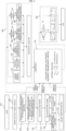
- FIG. 1 is a flowchart of a driving control method with optimal efficiency according to an embodiment of the present disclosure.
- the driving control method of this embodiment may be implemented as a vehicle driving control device and mounted in a vehicle.
- the driving control device includes a travel strategy control unit and a travel assistant unit, and a detailed description will be given later.
- the driving control method of this embodiment may be started when a driver selects a travel mode (S10).
- a travel mode selector such as a selection button or a lever for selecting a travel mode such as cruise control, smart cruise control, and pulse and glide may be provided in a vehicle within reach of a driver.
- the driving control method of this embodiment may be applied and implemented as an added part to the conventional traveling technology unless there is a particular reason that the method cannot be applied. For example, by applying the control method of this embodiment to cruise control, it may be possible to implement traveling with improved energy efficiency compared to traveling controlled by the conventional cruise control.
- the driving control technology to which the driving control method of the present embodiment is applied may be named differently from the conventional technology, and may be exemplarily referred to as "eco cruise control".
- the travel mode selector may be configured for a driver to select the eco cruise control, and when a driver selects the eco cruise control, the control method of this embodiment may be implemented.
- the driving control method according to this embodiment may be implemented in such a way that an additional function is added by a driver selection while driving control is performed by another driving technique. For example, when an additionally provided button "eco" is selected while a vehicle is traveling in a general cruise control travel mode, the general cruise control travel mode may be switched to the cruise control travel mode to which the control method of this embodiment is applied.
- a driver sets a target velocity (S20).
- the target velocity may be determined by a driver's selection or may be automatically set to one at which the vehicle is currently traveling.
- setting of the target velocity (S20) may precede the starting (S10) of the control method of this embodiment.
- the target velocity is set (S20), and then, when the "eco" button is input, the control method of this embodiment is executed (S10).
- the order between starting the method and setting the target velocity is not limited to the control method of this embodiment, and may vary depending on the circumstances of an implemented embodiment.
- a prediction horizon is determined and traveling environment information on the prediction horizon is collected (S40) .
- an objective function is generated (S50). To this end, first, wheel power is calculated (S51), battery power is calculated using the calculated wheel power (S52), and then, the battery power is approximated (S54).
- a target-velocity-following function is generated according to the target velocity value set by a driver (S53), then each weight is determined together with the approximated battery power function so as to generate an objective function (S55) .
- constraints such as an average velocity constraint, a traveling velocity band constraint, a motor constraint according to a vehicle velocity, a safe distance constraint from a preceding vehicle, and a safe velocity constraint according to a road curvature are collected (S60).
- An optimal solution of the objective function for the corresponding prediction horizon is calculated by adding the constraints, thereby outputting traction force and/or braking force (S70).
- the output braking force is distributed to regenerative braking and/or mechanical braking (S80).
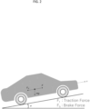
- FIG. 2 shows a vehicle traveling on a road having a longitudinal slope angle ⁇ , and the longitudinal dynamics equation for the vehicle is as shown in Equation 1 below.
- 1 2 mv k + 1 2 ⁇ 1 2 mv k 2 ⁇ s F t ⁇ F b ⁇ F roll ⁇ F air ⁇ F g
- v(k) denotes the velocity in a k-th step (refer to FIG. 6 and the description on the step of prediction horizon to be described later)
- F t denotes wheel traction force
- F b denotes wheel braking force
- m denotes mass of vehicle
- F roll denotes rolling resistance
- F air denotes air resistance
- F g denotes gravity resistance
- ⁇ s denotes movement distance in one step.
- Equation 2 models of state variable v 2 and input variables F t and F b may be obtained as in Equation 2 below.
- ⁇ denotes air density
- C d denotes coefficient of drag
- C r denotes coefficient of rolling resistance
- Equation 4 The models of state variable in Equation 2 for each step may be expressed as Equation 4 below.
- x 1 A p x 0 + B p u 0 + B ⁇ ⁇ ⁇ 1
- x 2 A p x 1 + B p u 1 + B ⁇ ⁇ ⁇ 2
- x 3 A p x 2 + B p u 2 + B ⁇ ⁇ ⁇ 3 . . .
- step S40 Determining prediction horizon and collecting traveling environment information on the corresponding section in step S40
- a prediction horizon corresponds to a section to use information for calculating an optimal solution (target traction force and braking force) in the present control method.
- the prediction horizon may be set based on distance, but may also be set based on time.
- the optimal solution may be calculated by each step using information on the entire prediction horizon.
- the length of one step may be defined as ⁇ s in the case of distance-based step and defined as ⁇ t in the case of time-based step.
- the prediction horizon is kept constant at 1,500 m, but the present disclosure is not limited thereto.
- FIG. 3 shows the results of examples in which the optimal solution is calculated by changing the prediction horizon to 500 m, 1000 m, and 1,500 m for the total travel distance of 5,000 m.
- the road used in the embodiment of FIG. 3 includes a steel plate section in a section from 2,000 m to 3,000 m as shown, and the length of one step stays at 20 m.
- traveling environment information on the prediction horizon is collected.
- the traveling environment information may include real-time variable information and non-variation information, which does not vary at least for the duration of traveling in the corresponding prediction horizon.
- real-time variable information includes the distance from a preceding vehicle
- non-variable information includes road shape-related information such as curvature and slope of the road, information on speed limit assigned to a specific road section, and information on the location of a traffic enforcement camera.
- the information on the distance from a preceding vehicle may be collected using a distance measuring sensor such as radar or LiDAR, and all of the above-described non-variable information may be collected from map data of a navigation system.
- a distance measuring sensor such as radar or LiDAR
- all of the above-described non-variable information may be collected from map data of a navigation system.
- a wheel power P m may be defined as Equation 5 below.
- P m F t v
- time-based battery power may be defined as Equation 6 below using the wheel power.
- ⁇ m denotes motor efficiency
- ⁇ b denotes charge and discharge efficiency of a battery.
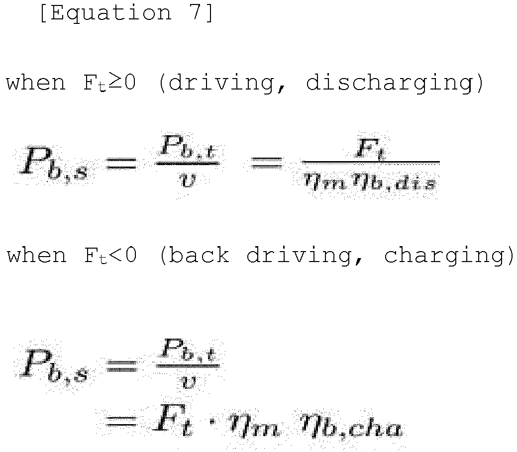
- distance-based battery power may be defined as Equation 7 below.
- Approximation of battery power may be time-based or distance-based. For the sake of describing convenience, the case of distance-based approximation will be described below.
- Battery power may be approximated as a linear plane or a quadratic plane on state variable and input variable planes.
- FIG. 4A shows linear planar approximation
- FIG. 4B shows quadratic planar approximation.
- a solution can be obtained only at the vertex of a constraint (Au ⁇ B, all constraints may be expressed as input variables using the state variable model as will described later) when calculating an optimal solution to an objective function J. Therefore, it is preferable to use quadratic planar approximation.
- battery power may be expressed as Equation 8 below with functions of state variables and input variables, and coefficients p00, p10, p01, and p02 are obtained by quadratic planar fitting.
- P b , s F t v 2 p 00 + p 10 ⁇ v 2 + p 01 ⁇ F t + p 20 ⁇ v 4 + p 11 ⁇ v 2 F t + p 02 ⁇ F t 2
- the fitting is performed only in a region from 123 kph to 278 kph, which is the velocity band region of +10 kph.
- the battery power function may be expressed as a function of only the input variable, with no state variable, using the above-described model.
- the target-velocity-following function is to follow the target velocity in the case of traveling on a flat road without slope, and may be defined as a function as in Equation 9 below.
- the total distance of the prediction horizon is "S ph " as shown in FIG. 6 , and is calculated by dividing the same into n steps of ⁇ s.
- Equation 10 The final objective function obtained by summing the battery function and the target-velocity-following function for the prediction horizon is as shown in Equation 10 below.
- ⁇ is for soft constraint and allows instantaneous violation of the constraint.
- ⁇ may be set for turbo speed limit condition, the amount of violation is indicated as ⁇ , and the amount of violation is determined by setting primary and secondary weights s 1 and s 2 in the objective function.
- w 1 and w2 are weights, more specifically, w 1 is a weight for battery power, and w 2 is a weight for the target-velocity-following function.
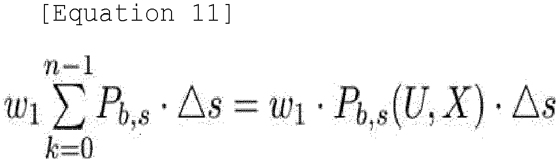
- the state variable and input variable for n steps may be expressed in column vector forms U and X, respectively, whereby the battery power function of Equation 10 may be expressed in vector form as shown in Equation 11 below.
- Equation 11 the battery power function of Equation 10 may be expressed in vector form as shown in Equation 11 below.
- Equation 11 above may be expressed as Equation 12 below by the quadratic planar approximation as described above.
- Equation 13 the state variable model is expressed in a vector form as in Equation 13 below, and when substituted into Equation 12, the battery function may be expressed as in Equation 14 below.
- X A ⁇ x 0 + B ⁇ U + B ⁇ ⁇ ⁇ w 1 p 10 B ⁇ U ⁇ s + w 1 p 01 ⁇ U ⁇ s + w 1 ⁇ p 11 A ⁇ x 0 + B ⁇ ⁇ ⁇ U ⁇ s + U T w 1 p 11 B ⁇ T + p 02 ⁇ s ⁇ U
- the target-velocity-following function may also be expressed in a vector form, and may be expressed as Equation 15 below.
- C is a constant and may be excluded.
- the average velocity constraint is, for example, to follow the cruise control target velocity, and may be set as a condition in which the average value of v 2 is greater than the square of the predetermined target velocity v target within the prediction horizon.
- the average velocity constraint may be expressed as Equation 16 below. x 1 + x 2 + ⁇ + x N p N p ⁇ V target 2 ⁇ ⁇
- ⁇ denotes an adjustment parameter
- N p is an integer indicating the prediction horizon, which is the same as n in Equation 10 above.
- ⁇ is inversely proportional to efficiency improvement and travel time.
- the above constraint may also be expressed in a vector form by substituting and applying the state variable model.
- the constraint is, for example, a velocity band constraint of + ⁇ v with respect to the cruise control target velocity.
- cruise control target velocity v target when cruise control target velocity v target is set, it is allowed to deviate from the target velocity v target within the range between the maximum velocity v max and the minimum velocity v min before, after, and while traveling on downhill roads.
- section 'A' before traveling on downhill roads, during section 'A', the vehicle is decelerated to the minimum speed v min at or under the target velocity v target , in a part of section 'B', including the initial stage of the traveling on downhill roads, the vehicle accelerates and maintains the maximum speed v max while performing regenerative braking, and then in section 'C', which is after the traveling on downhill roads, the vehicle returns to the target velocity v target while increasing energy efficiency through neutral control.
- Equation 17 The traveling velocity band constraint is expressed as Equation 17 below. v min 2 ⁇ ⁇ ⁇ x ⁇ v max 2 , ⁇ ⁇ 0
- ⁇ is for treating the constraint as a soft constraint to secure a safe distance from a preceding vehicle.
- the constraint is a condition due to the torque limit of a driving motor.
- the left diagram of FIG. 8 shows a motor diagram, which may be the same as the diagram on the right when the left diagram is changed by state variable and input variable and the curved part is approximated into a straight line.
- F max and F min are respectively the same as in Equation 18 below.
- F max g r r w T max ⁇ ⁇ trans
- F min g r r w T min ⁇ ⁇ trans
- Equation 19 the constraint limits the traction force and the braking force within the shaded region in the right diagram of FIG. 8 , and the maximum and minimum conditions are expressed as Equation 19 below.
- F t,max and F t,min are respectively the same as in Equation 20 below.
- F t , min max F min , ⁇ ax ⁇ b
- F t , max min F max , ax + b
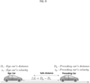
- the constraint is a condition for securing a safe distance from a preceding vehicle as shown in FIG. 9 .
- the distance ⁇ L between an ego vehicle and a preceding vehicle must be greater than a predetermined safe distance ⁇ L S .
- the constraint is expressed in Equation 21 below. ⁇ L k + 1 ⁇ ⁇ L s k + 1
- Equation 22 Equation 22 below using the proportional constant h and the minimum safe distance l at the time of stopping.
- ⁇ L s k + 1 h ⁇ v e k + 1 + l
- Equation 23 v k 2 ⁇ ⁇ L k ⁇ l h 2
- the constraint is a condition that limits the maximum velocity for safety when the vehicle performs turning.
- the maximum velocity for safety may be obtained under the condition that the sum of all forces acting on the vehicle with respect to the lateral inclination of the road (road bank slope) ⁇ , the road curvature k , and the friction coefficient f of the road surface becomes 0 (zero).
- the constraint limiting the velocity to the maximum velocity or less may be expressed as Equation 24 below.
- g denotes the gravitational acceleration
- constraints are not limited thereto, and it is natural that constraints may be further added in consideration of safety, efficiency, driver's demands, and the like.
- constraints may also be expressed as input variables using the state variable model equation, and may be expressed in a vector form.
- This step is a process of calculating an optimal solution by applying the constraints to the above-described objective function.
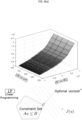
- FIG. 11 schematically shows the process of calculating an optimal solution, and as shown, an optimal traction force u1 opt and an optimal braking force u2 opt are calculated by the quadratic programming method by applying the above-mentioned constraints.
- the optimal solution may be obtained as an optimal solution vector u* for all the steps within the prediction horizon, and only the first input value (the optimal solution corresponding to the first step in FIG. 6 ) may be used.
- an optimal solution is expressed as a traction force and a braking force, and is scalable by an iterative structure in which the optimal solution of the quadratic programming method is obtained at every step (distance step ⁇ s or time step ⁇ t) and is controlled using only the first input value, i.e., model predictive control (MPC).
- MPC model predictive control
- the distribution of regenerative braking may be determined according to the magnitude of the braking force obtained by the optimal solution (S80), which will be described below.
- FIG. 12 shows the distribution of regenerative braking for three cases.
- Eh denotes gravitational potential energy (just before traveling on downhill road)
- Ed denotes kinetic energy
- Er denotes regenerative brake energy
- Eb denotes energy dissipated by mechanical braking.
- the calculated F b * is greater than 0 and is less than the 'absolute value of F min ', which is a threshold value. Accordingly, all of the calculated braking force is distributed to regenerative braking.
- the traction force is controlled as 'F t * - F b *' in consideration of regenerative braking.
- F min is a value expressing the maximum limit of regenerative braking of the motor as a force at the wheel in consideration of the radius, gear ratio, efficiency, etc.
- the gravitational potential energy is very large, so that the calculated F b * is greater than or equal to the threshold value.
- regenerative braking is distributed to the maximum, and the difference 'F b * - F min ' is distributed to mechanical braking.
- FIG. 13 shows the control states of the velocity and traction force, regenerative braking and mechanical braking, etc. according to the movement distance of the vehicle in these three cases.
- FIGS. 14A , 14B , and 14C show simulation results of velocity, traction force, and battery state (SOC) when a vehicle is traveling on three types of roads by applying the method of this embodiment.
- SOC battery state
- the energy efficiency improvement may be low for the terrain only including simple flat and uphill sections, but the efficiency is greatly improved on downhill terrain.
- control method of the present disclosure may be implemented by being included in a vehicle driving control device 10 including a travel strategy control unit 11 and a travel assistant unit 12.
- a target velocity for cruise control is determined, road slope and curvature information, speed limit information, and traffic enforcement camera location information are collected from navigation map data 20 (e.g., a server or a recording medium) for each prediction horizon, and information on the distance to a preceding vehicle information is collected from a radar or LiDAR sensor 30.
- navigation map data 20 e.g., a server or a recording medium
- information on the distance to a preceding vehicle information is collected from a radar or LiDAR sensor 30.
- the optimal drive force and braking force for the corresponding prediction horizon are obtained through the above-described equations and the process of calculating the optimal solution.
- the obtained results of drive force and braking force are transmitted to the travel assistant unit 12, and the travel assistant unit 12 transmits a target driving torque and braking force to a motor 50 and a brake 60 so as to allow the same to be used for control.
- the distribution of regenerative braking described above may be determined depending on the magnitude of the braking force calculated by the optimal solution, and the distribution result may be transmitted to the travel assistant unit 12.
- F b,r denotes the regenerative braking force
- F b,m denotes the mechanical braking force of the brake.
- the travel strategy control unit 11 may include a data input and output device, at least one processor configured to perform judgment, calculation, determination, and the like, and a non-transitory memory configured to store an operating system or logic commands, input and output information, etc.
- a communication device may be added.
- the communication device may be separately provided in the vehicle and the travel strategy control unit 11 may be configured to receive the corresponding information only through the input and output device.
- the travel assistant unit 12 may include a data input and output device, at least one processor configured to perform judgment, calculation, determination, and the like, and a non-transitory memory configured to store an operating system or logic commands, input and output information, etc.
- the travel strategy control unit 11 and the travel assistant unit 12 do not need to be physically separated and may be configured as an integrated unit.
- Such an integrated unit may also include a data input and output device, at least one processor configured to perform judgment, calculation, determination, and the like, and a non-transitory memory configured to store an operating system or logic commands, input and output information, etc.
- one processor may perform functions such as judgment and calculation for the travel strategy control unit 11 as well as functions for the travel assistant unit 12.
- the vehicle driving control device 10 may be applied to any vehicle that can be driven by a motor, such as a hybrid vehicle or an electric vehicle.
- At least one embodiment of the present disclosure may achieve improved driving control in an energy-efficient manner by its own travel control technology or by being combined with existing travel control technologies such as cruise control.
Landscapes
- Engineering & Computer Science (AREA)
- Transportation (AREA)
- Mechanical Engineering (AREA)
- Chemical & Material Sciences (AREA)
- Combustion & Propulsion (AREA)
- Automation & Control Theory (AREA)
- Physics & Mathematics (AREA)
- Mathematical Physics (AREA)
- Power Engineering (AREA)
- Human Computer Interaction (AREA)
- Electric Propulsion And Braking For Vehicles (AREA)
Abstract
Description
- This application claims the benefit of priority to
Korean Patent Application No. 10-2021-0180478, filed on December 16, 2021 - The present disclosure relates to a vehicle driving control method, and more particularly, to a method of controlling driving of a vehicle with optimal battery efficiency.
- Recently, driving technology for improving the driving convenience for a driver has been continuously developed, and the function thereof is gradually improving.
- For example, cruise control has evolved into smart cruise control technology that is controlled by following the stopping and starting of a preceding vehicle beyond the simple cruise control level. Accordingly, cruise control driving has become available not only on leisurely suburban roads, but also on rather congested roads such as in downtown areas.
- Such cruise control is expected to be more advanced with the development of autonomous driving technology.
- However, since the conventional cruise control is designed in consideration of driving convenience or safety only, it is insufficient because the aspect of energy efficiency is not considered.
- According to the policy for reducing CO2 emission, countries around the world are strengthening support for eco-friendly vehicles such as an electric vehicle, and following this trend, it is expected that a vehicle with an internal combustion engine will not be seen on the road in the near future.
- Such an eco-friendly vehicle is generally driven by a motor, which is driven by receiving power from eco-friendly energy. For example, a hybrid vehicle or an electric vehicle is driven by a motor driven by receiving power from a battery mounted in the vehicle.
- In the case of an electric vehicle, the mileage on a single battery charge is very important, and battery technology continues to be developed so as to improve energy efficiency. However, in addition to battery technology, driving control technology for driving a vehicle with optimal energy efficiency is important.
- Particularly, because the conventional cruise control is insufficient in terms of energy efficiency as described above, a driving control method with optimal efficiency for increasing the energy efficiency of an electric vehicle is needed.
- The information disclosed in the Background section above is to aid in the understanding of the background of the present disclosure, and should not be taken as acknowledgement that this information forms any part of prior art.
- Accordingly, the present disclosure is directed to a vehicle driving control method that substantially obviates one or more problems due to limitations and disadvantages of the related art.
- An object of the present disclosure is to provide a driving control method with optimal efficiency for an eco-friendly vehicle driven by electric power.
- When applied to cruise control, a driving control method of achieving cruise control driving with optimum efficiency is provided.
- Additional advantages, objects, and features of the disclosure will be set forth in part in the description which follows and in part will become apparent to those having ordinary skill in the art upon examination of the following or may be learned from practice of the disclosure. The objectives and other advantages of the disclosure may be realized and attained by the structure particularly pointed out in the written description and claims hereof as well as the appended drawings.
- To achieve these objects and other advantages and in accordance with the purpose of the disclosure, as embodied and broadly described herein, there is provided a vehicle driving control method with optimal efficiency, the method including obtaining a state variable model of a longitudinal dynamics equation of a vehicle based on a velocity-related state variable and a wheel drive input variable, calculating wheel power using the velocity-related state variable and the wheel drive input variable, calculating battery power using the calculated wheel power, obtaining an approximated battery power function using the calculated battery power, and outputting a wheel drive control target by calculating a minimum solution by using the approximated battery power function as an objective function and applying at least one constraint to the objective function.
- The wheel drive control target may be a control target related to wheel traction force or wheel braking force.
- The velocity-related state variable may include a square of velocity, and the wheel drive input variable may include wheel traction force and wheel braking force.
- Here, the calculating of battery power may be performed by multiplying the calculated wheel power by at least one of motor efficiency, battery charging and discharging efficiency, and reducer efficiency.
- The state variable model may be defined by a relationship between work done by a wheel and a change in vehicle kinetic energy under air resistance, rolling resistance, and gravity resistance for a predetermined distance movement.
- In addition, the objective function may further include a target-velocity-following function.
- Additionally, the at least one constraint may include at least one of an average velocity constraint, a traveling velocity band constraint, a motor constraint according to a vehicle velocity, a safe distance constraint from a preceding vehicle, or a safe velocity constraint according to a road curvature.
- The obtaining of a state variable model, the calculating of wheel power, the calculating of battery power, the approximating of the battery power, and the outputting of a wheel drive control target may be performed for a set forward prediction horizon.
- In addition, the set forward prediction horizon may be divided into a plurality of distance-based or time-based steps, the minimum solution may be calculated for all of the plurality of distance-based or time-based steps, and the wheel drive control target may be obtained from a minimum solution corresponding to a first step among the plurality of distance-based or time-based steps.
- In addition, the set forward prediction horizon may be defined as a range of time distance or traveling distance. For example, the set forward prediction horizon may be set to 1,500 m when defined as a traveling distance range, and set to 108 seconds when defined as a time distance range.
- The setting of the set forward prediction horizon may be constant. In other words, the size range of the set forward prediction horizon does not change according to traveling of a vehicle and may be maintained constant.
- Meanwhile, when the output wheel braking force is less than or equal to a predetermined value, all of the output wheel braking force may be distributed to regenerative braking force, and when the output wheel braking force exceeds the predetermined value, the output wheel braking force may be distributed to regenerative braking force and mechanical braking force.
- The approximated battery power function may comprise a quadratic function of the velocity-related state variable and the wheel drive input variable.
- In addition, the method may further include receiving a selection of a cruise control travel mode by a user.
- Still further, the method may further include performing a brake or motor control of the vehicle based on the outputted wheel drive control target.
- Another object of the present disclosure is to provide a vehicle driving control device including a travel strategy control unit configured to collect curvature and slope information, speed limit information, and traffic enforcement camera location information for a road section in a set forward prediction horizon, collect information on a distance from a preceding vehicle from a sensor, and to calculate a minimum solution of an objective function by applying at least one constraint among an average velocity constraint, a traveling velocity band constraint, a motor constraint according to a vehicle velocity, a safe distance constraint from a preceding vehicle, and a safe velocity constraint according to a road curvature, wherein a battery power for traveling in the set forward prediction horizon is used as the objective function, and a travel assistant unit configured to output a control signal so as to control a motor and a brake with traction force and braking force derived from the minimum solution.
- It is to be understood that both the foregoing general description and the following detailed description of the present disclosure are exemplary and explanatory and are intended to provide further explanation of the disclosure as claimed.
- The accompanying drawings, which are included to provide a further understanding of the disclosure and are incorporated in and constitute a part of this application, illustrate embodiment(s) of the disclosure, without being limited thereto, and together with the description help for the better understanding of the disclosure. In the drawings:
-
FIG. 1 shows a flowchart of an embodiment of the present disclosure; -
FIG. 2 is a schematic diagram of a traveling vehicle for explaining an embodiment of state variable modeling of a longitudinal dynamics equation; -
FIG. 3 shows a simulation result according to the length of prediction horizon in an embodiment of the present disclosure; -
FIG. 4 shows an example of approximating battery power on linear and quadratic planes; -
FIG. 5 shows an example of approximating battery power on a quadratic plane based on a target velocity set in cruise control; -
FIG. 6 shows an example in which a prediction horizon is divided into n steps; -
FIG. 7 explains an example of "traveling velocity band constraint"; -
FIG. 8 explains an example of "motor constraint according to a vehicle velocity"; -
FIG. 9 explains an example of "safe distance constraint from preceding vehicle"; -
FIG. 10 explains an example of "safe velocity constraint according to road curvature"; -
FIG. 11 schematically shows the process of finding an optimal solution of an objective function that satisfies constraint; -
FIG. 12 is an example of distribution of regenerative braking and/or mechanical braking; -
FIG. 13 is a diagram schematically illustrating states such as road height, velocity, traction force, regenerative braking force, and mechanical braking force according to traveling of a vehicle for each case ofFIG. 12 ; -
FIG. 14 is a simulation result of one embodiment of the present disclosure according to three road types; and -
FIG. 15 shows a driving control device according to an embodiment of the present disclosure. - Since the present disclosure may be variously changed and may have various embodiments, exemplary embodiments will be illustrated and described in the drawings. However, this is not intended to limit the present disclosure to the exemplary embodiments, and it should be understood to include all modifications, equivalents and substitutes included in the idea and scope of the present disclosure.
- As used herein, the suffixes "module" and "unit" are used only for descriptive distinction between components, and should not be construed as an assumption that the components are physically and chemically distinguished or separated, or that the components can be distinguished or separated as such.
- It will be understood that, although the terms first, second, etc. may be used herein to describe various elements, these elements should not be limited by these terms. These terms are generally only used to distinguish one element from another.
- The term "and/or" is used to include any combination of plural subject items. For example, "A and/or B" includes all three cases such as "A", "B", and "A and B".
- It will be understood that when an element is referred to as being "connected to" another element, the element can be directly connected to the other element, or intervening elements may also be present.
- In the following description of the embodiments, it will be understood that, when an element such as a layer (film), region, pattern, or structure is referred to as being "on" or "under" another element, it can be "directly" on or under the other element, or can be "indirectly" disposed such that an intervening element is also present. In addition, the criteria for the terms "upper/above" or "lower/under" is, in principle, used merely to indicate the relative positional relationship between the components based on the figure shown in the drawings for convenience, unless it is naturally determined from the nature of each of the components or between the same, or unless otherwise expressed in the specification, and should not be construed as limiting the location of the actual components. For example, "B located above A" merely indicates that B is illustrated as being located above A in the drawing, unless otherwise stated or in the case in which B must be located above A due to the nature of A or B, and in the actual product, etc., B may be located under A, and B and A may be arranged left and right horizontally.
- In addition, since the thickness or size of each layer (film), region, pattern, or structure in the drawings may be changed for clarity and convenience of description, the dimensions of constituent elements may not accurately reflect the actual dimensions.
- The terminology used herein is for the purpose of describing particular embodiments only, and is not intended to be limiting. A singular representation may include a plural representation unless the context clearly indicates otherwise. As used herein, the singular forms "a", "an", and "the" are intended to include the plural forms as well, unless the context clearly indicates otherwise. It will be further understood that the terms "comprise", "have", etc., when used in this specification, specify the presence of stated features, integers, steps, operations, elements, components, or combinations thereof, but do not preclude the presence or addition of one or more other features, integers, steps, operations, elements, components, or combinations thereof.
- Unless otherwise defined, all terms including technical and scientific terms used herein have the same meanings as those commonly understood by one of ordinary skill in the art to which this disclosure belongs. It will be further understood that terms, such as those defined in commonly used dictionaries, should be interpreted as having meanings consistent with their meanings in the context of the relevant art and the present disclosure, and are not to be interpreted in an idealized or overly formal sense unless expressly so defined herein.
- In addition, "unit" or "control unit" is merely a term widely used in naming a controller that controls a specific function of a vehicle, and does not mean a generic functional unit. For example, each unit or control unit according to various aspects of the present disclosure may include a communication device (e.g., transceiver or processor) configured to communicate with another controller or sensor so as to control the function it is responsible for, a non-transitory memory configured to store an operating system or logic commands, input and output information, etc., and one or more processors configured to perform judgment, calculation, decision, etc. needed in controlling the function it is responsible for.
-
FIG. 1 is a flowchart of a driving control method with optimal efficiency according to an embodiment of the present disclosure. - First, the driving control method of this embodiment may be implemented as a vehicle driving control device and mounted in a vehicle. For example, the driving control device includes a travel strategy control unit and a travel assistant unit, and a detailed description will be given later.
- The driving control method of this embodiment may be started when a driver selects a travel mode (S10). For example, a travel mode selector such as a selection button or a lever for selecting a travel mode such as cruise control, smart cruise control, and pulse and glide may be provided in a vehicle within reach of a driver.
- The driving control method of this embodiment may be applied and implemented as an added part to the conventional traveling technology unless there is a particular reason that the method cannot be applied. For example, by applying the control method of this embodiment to cruise control, it may be possible to implement traveling with improved energy efficiency compared to traveling controlled by the conventional cruise control.
- In addition, the driving control technology to which the driving control method of the present embodiment is applied may be named differently from the conventional technology, and may be exemplarily referred to as "eco cruise control".
- In this case, the travel mode selector may be configured for a driver to select the eco cruise control, and when a driver selects the eco cruise control, the control method of this embodiment may be implemented.
- Meanwhile, the driving control method according to this embodiment may be implemented in such a way that an additional function is added by a driver selection while driving control is performed by another driving technique. For example, when an additionally provided button "eco" is selected while a vehicle is traveling in a general cruise control travel mode, the general cruise control travel mode may be switched to the cruise control travel mode to which the control method of this embodiment is applied.
- When starting the control method of this embodiment (S10), first, a driver sets a target velocity (S20). For example, the target velocity may be determined by a driver's selection or may be automatically set to one at which the vehicle is currently traveling.
- Here, in the case of the above-described "eco" button, setting of the target velocity (S20) may precede the starting (S10) of the control method of this embodiment. In other words, when the general cruise control is selected, the target velocity is set (S20), and then, when the "eco" button is input, the control method of this embodiment is executed (S10).
- In other words, the order between starting the method and setting the target velocity is not limited to the control method of this embodiment, and may vary depending on the circumstances of an implemented embodiment.
- Next, the obtaining of a state variable model of a longitudinal dynamics equation is performed (S30).
- Then, a prediction horizon is determined and traveling environment information on the prediction horizon is collected (S40) .
- Next, an objective function is generated (S50). To this end, first, wheel power is calculated (S51), battery power is calculated using the calculated wheel power (S52), and then, the battery power is approximated (S54).
- A target-velocity-following function is generated according to the target velocity value set by a driver (S53), then each weight is determined together with the approximated battery power function so as to generate an objective function (S55) .
- Here, constraints such as an average velocity constraint, a traveling velocity band constraint, a motor constraint according to a vehicle velocity, a safe distance constraint from a preceding vehicle, and a safe velocity constraint according to a road curvature are collected (S60).
- An optimal solution of the objective function for the corresponding prediction horizon is calculated by adding the constraints, thereby outputting traction force and/or braking force (S70).
- Here, the output braking force is distributed to regenerative braking and/or mechanical braking (S80).
- Hereinafter, each step of the control method of this embodiment will be described in detail.
-
FIG. 2 shows a vehicle traveling on a road having a longitudinal slope angle θ, and the longitudinal dynamics equation for the vehicle is as shown inEquation 1 below.

- Here, v(k) denotes the velocity in a k-th step (refer to
FIG. 6 and the description on the step of prediction horizon to be described later), Ft denotes wheel traction force, Fb denotes wheel braking force, m denotes mass of vehicle, Froll denotes rolling resistance, Fair denotes air resistance, Fg denotes gravity resistance, and Δs denotes movement distance in one step. - From the dynamics equation, models of state variable v2 and input variables Ft and Fb may be obtained as in
Equation 2 below.

- Here, Ap, Bp, Bϕ, and Φ are as in
Equation 3 below.

- Here, ρ denotes air density, Cd denotes coefficient of drag, and Cr denotes coefficient of rolling resistance.
- The models of state variable in
Equation 2 for each step may be expressed as Equation 4 below.

- A prediction horizon corresponds to a section to use information for calculating an optimal solution (target traction force and braking force) in the present control method.
- The prediction horizon may be set based on distance, but may also be set based on time.
- The optimal solution may be calculated by each step using information on the entire prediction horizon.
- In addition, the length of one step may be defined as Δs in the case of distance-based step and defined as Δt in the case of time-based step.
- For example, when one step Δs is 20 m and the prediction horizon is 1,500 m, an optimal solution is calculated using the information on a
section 0 to 1,500 m so as to obtain target traction force and braking force of the driving control in arange 0 to 20 m, then a section from 20 m to 1,520 m is set to be a follow-up prediction horizon so as to calculate an optimal solution using the corresponding section information, thereby obtaining target traction force and braking force for a range from 20 m to 40 m. The same process goes for subsequent steps and prediction horizons. In this example, the prediction horizon is kept constant at 1,500 m, but the present disclosure is not limited thereto. -
FIG. 3 shows the results of examples in which the optimal solution is calculated by changing the prediction horizon to 500 m, 1000 m, and 1,500 m for the total travel distance of 5,000 m. - The road used in the embodiment of
FIG. 3 includes a steel plate section in a section from 2,000 m to 3,000 m as shown, and the length of one step stays at 20 m. - For the improvement in energy efficiency for the three cases, it is shown to be 3.5% for the prediction horizon of 500 m, 5.4% for the prediction horizon of 1,000 m, and 5.9% for the prediction horizon of 1,500 m, and therefore, it can be seen that the efficiency is most improved in the case of the prediction horizon of 1,500 m.
- The longer the prediction horizon, the more information is used, so the efficiency may be further improved. However, the computational load increases as the prediction horizon gets longer, and thus an appropriate compromise needs to be made for the length of the prediction horizon.
- Once the prediction horizon is determined, traveling environment information on the prediction horizon is collected.
- The traveling environment information may include real-time variable information and non-variation information, which does not vary at least for the duration of traveling in the corresponding prediction horizon.
- For example, real-time variable information includes the distance from a preceding vehicle, and non-variable information includes road shape-related information such as curvature and slope of the road, information on speed limit assigned to a specific road section, and information on the location of a traffic enforcement camera.
- Here, for example, the information on the distance from a preceding vehicle may be collected using a distance measuring sensor such as radar or LiDAR, and all of the above-described non-variable information may be collected from map data of a navigation system. Of course, it is not necessary to limit the means configured to obtain non-variable information to the navigation system.
- First, a wheel power Pm may be defined as Equation 5 below.

- Since an energy source for driving a wheel is a battery, time-based battery power may be defined as Equation 6 below using the wheel power.
- [Equation 6] when Ft≥0 (driving, discharging)


- Here, ηm denotes motor efficiency, and ηb denotes charge and discharge efficiency of a battery.
- In addition, distance-based battery power may be defined as Equation 7 below.
- Approximation of battery power may be time-based or distance-based. For the sake of describing convenience, the case of distance-based approximation will be described below.
- Battery power may be approximated as a linear plane or a quadratic plane on state variable and input variable planes.
-
FIG. 4A shows linear planar approximation, andFIG. 4B shows quadratic planar approximation. In the case of linear planar approximation, a solution can be obtained only at the vertex of a constraint (Au < B, all constraints may be expressed as input variables using the state variable model as will described later) when calculating an optimal solution to an objective function J. Therefore, it is preferable to use quadratic planar approximation. - In the case of quadratic planar approximation, battery power may be expressed as
Equation 8 below with functions of state variables and input variables, and coefficients p00, p10, p01, and p02 are obtained by quadratic planar fitting.
- Here, because an error may be large when the entire trajectory is fitted to the quadratic plane, only a set band area of the target velocity is selected and fitted so as to improve accuracy.
- In other words, as shown in
FIG. 5 , when a driver selects thevelocity 50 kph as a cruise control setting, the fitting is performed only in a region from 123 kph to 278 kph, which is the velocity band region of +10 kph. - Meanwhile, the battery power function may be expressed as a function of only the input variable, with no state variable, using the above-described model.
- The target-velocity-following function is to follow the target velocity in the case of traveling on a flat road without slope, and may be defined as a function as in Equation 9 below.

- First, for example, the total distance of the prediction horizon is "Sph" as shown in
FIG. 6 , and is calculated by dividing the same into n steps of Δs. - The final objective function obtained by summing the battery function and the target-velocity-following function for the prediction horizon is as shown in
Equation 10 below.
- Here, ε is for soft constraint and allows instantaneous violation of the constraint. For example, ε may be set for turbo speed limit condition, the amount of violation is indicated as ε, and the amount of violation is determined by setting primary and secondary weights s1 and s2 in the objective function.
- In addition, w1 and w2 are weights, more specifically, w1 is a weight for battery power, and w2 is a weight for the target-velocity-following function.
- The state variable and input variable for n steps may be expressed in column vector forms U and X, respectively, whereby the battery power function of
Equation 10 may be expressed in vector form as shown inEquation 11 below.
-
Equation 11 above may be expressed asEquation 12 below by the quadratic planar approximation as described above.
- In addition, the state variable model is expressed in a vector form as in Equation 13 below, and when substituted into
Equation 12, the battery function may be expressed as in Equation 14 below.


- The target-velocity-following function may also be expressed in a vector form, and may be expressed as
Equation 15 below.
- Here, C is a constant and may be excluded.
- The average velocity constraint is, for example, to follow the cruise control target velocity, and may be set as a condition in which the average value of v2 is greater than the square of the predetermined target velocity vtarget within the prediction horizon.
- In other words, the average velocity constraint may be expressed as Equation 16 below.

- Here, α denotes an adjustment parameter, and Np is an integer indicating the prediction horizon, which is the same as n in
Equation 10 above. - When α is set as a time penalty, additional efficiency improvement may be achieved even through there is a disadvantage in traveling time.
- Due to characteristics of electric vehicles, in the case in which the remaining travelable distance is insufficient in terms of battery power and thus active using of energy-saving driving is needed, this may be addressed using α. In other words, α is inversely proportional to efficiency improvement and travel time.
- Meanwhile, although omitted from this specification, the above constraint may also be expressed in a vector form by substituting and applying the state variable model.
- The constraint is, for example, a velocity band constraint of +Δv with respect to the cruise control target velocity.
- When traveling on a road with a longitudinal slope, an allowable +Δv in addition to the target velocity is needed for energy-efficient traveling.
- For example, as shown in
FIG. 7 , when cruise control target velocity vtarget is set, it is allowed to deviate from the target velocity vtarget within the range between the maximum velocity vmax and the minimum velocity vmin before, after, and while traveling on downhill roads. - In other words, before traveling on downhill roads, during section 'A', the vehicle is decelerated to the minimum speed vmin at or under the target velocity vtarget, in a part of section 'B', including the initial stage of the traveling on downhill roads, the vehicle accelerates and maintains the maximum speed vmax while performing regenerative braking, and then in section 'C', which is after the traveling on downhill roads, the vehicle returns to the target velocity vtarget while increasing energy efficiency through neutral control.
- The traveling velocity band constraint is expressed as Equation 17 below.

- Here, ε is for treating the constraint as a soft constraint to secure a safe distance from a preceding vehicle.
- The constraint is a condition due to the torque limit of a driving motor.
- The left diagram of
FIG. 8 shows a motor diagram, which may be the same as the diagram on the right when the left diagram is changed by state variable and input variable and the curved part is approximated into a straight line. - In
FIG. 8 , Fmax and Fmin are respectively the same as in Equation 18 below.
- For example, the constraint limits the traction force and the braking force within the shaded region in the right diagram of
FIG. 8 , and the maximum and minimum conditions are expressed as Equation 19 below.

- Here, Ft,max and Ft,min are respectively the same as in
Equation 20 below.
- The constraint is a condition for securing a safe distance from a preceding vehicle as shown in
FIG. 9 . - The distance ΔL between an ego vehicle and a preceding vehicle must be greater than a predetermined safe distance ΔLS. In other words, the constraint is expressed in Equation 21 below.

- Here, the right side of the above equation may be defined as Equation 22 below using the proportional constant h and the minimum safe distance ℓ at the time of stopping.

- By substituting Equation 22 into Equation 21, the final present constraint may be expressed as Equation 23 below.

- The constraint is a condition that limits the maximum velocity for safety when the vehicle performs turning.
- In the state in which a vehicle travels as shown in
FIG. 10 , the maximum velocity for safety may be obtained under the condition that the sum of all forces acting on the vehicle with respect to the lateral inclination of the road (road bank slope) β, the road curvature k, and the friction coefficient f of the road surface becomes 0 (zero). The constraint limiting the velocity to the maximum velocity or less may be expressed as Equation 24 below.

- Here, g denotes the gravitational acceleration.
- Although five types of constraints have been described, constraints are not limited thereto, and it is natural that constraints may be further added in consideration of safety, efficiency, driver's demands, and the like.
- In addition, although omitted from this specification, all of the above described constraints may also be expressed as input variables using the state variable model equation, and may be expressed in a vector form.
- This step is a process of calculating an optimal solution by applying the constraints to the above-described objective function.
-
FIG. 11 schematically shows the process of calculating an optimal solution, and as shown, an optimal traction force u1opt and an optimal braking force u2opt are calculated by the quadratic programming method by applying the above-mentioned constraints. - The optimal solution may be obtained as an optimal solution vector u* for all the steps within the prediction horizon, and only the first input value (the optimal solution corresponding to the first step in
FIG. 6 ) may be used. - In other words, an optimal solution is expressed as a traction force and a braking force, and is scalable by an iterative structure in which the optimal solution of the quadratic programming method is obtained at every step (distance step Δs or time step Δt) and is controlled using only the first input value, i.e., model predictive control (MPC).
- The distribution of regenerative braking may be determined according to the magnitude of the braking force obtained by the optimal solution (S80), which will be described below.
- First,
FIG. 12 shows the distribution of regenerative braking for three cases. InFIG. 12 , Eh denotes gravitational potential energy (just before traveling on downhill road), Ed denotes kinetic energy, Er denotes regenerative brake energy, and Eb denotes energy dissipated by mechanical braking. - In
case 1, all the vehicle's gravitational potential energy is converted into kinetic energy by the traction force. Here, as a result of the optimal solution, the traction force Ft* is greater than or equal to 0, and the braking force Fb* is 0, so that no braking force is needed. - In
case 2, the calculated Fb* is greater than 0 and is less than the 'absolute value of Fmin', which is a threshold value. Accordingly, all of the calculated braking force is distributed to regenerative braking. Here, the traction force is controlled as 'Ft* - Fb*' in consideration of regenerative braking. Here, Fmin is a value expressing the maximum limit of regenerative braking of the motor as a force at the wheel in consideration of the radius, gear ratio, efficiency, etc. - In the
case 3, the gravitational potential energy is very large, so that the calculated Fb* is greater than or equal to the threshold value. Here, regenerative braking is distributed to the maximum, and the difference 'Fb* - Fmin' is distributed to mechanical braking. -
FIG. 13 shows the control states of the velocity and traction force, regenerative braking and mechanical braking, etc. according to the movement distance of the vehicle in these three cases. -
FIGS. 14A ,14B , and14C show simulation results of velocity, traction force, and battery state (SOC) when a vehicle is traveling on three types of roads by applying the method of this embodiment. Incase 1, where the downhill section is long and uphill is short, the improvement is 39%, and in thecase 2, where the downhill and uphill sections have the same slope and length, 11.3% improvement is achieved. Meanwhile, incase 3, where there is no downhill section and only an uphill section exists, just 2.7% improvement is achieved. - As can be seen from these results, in the control according to the present embodiment, the energy efficiency improvement may be low for the terrain only including simple flat and uphill sections, but the efficiency is greatly improved on downhill terrain.
- In addition, the effect of energy efficiency improvement is exhibited at the point of recognizing the time when the road slope changes and preemptively controlling the kinetic energy of the vehicle.
- Meanwhile, as shown in
FIG. 15 , the control method of the present disclosure may be implemented by being included in a vehicle drivingcontrol device 10 including a travelstrategy control unit 11 and atravel assistant unit 12. - When a driver selects, for example, "eco cruise" mode through the
travel mode selector 40, a target velocity for cruise control is determined, road slope and curvature information, speed limit information, and traffic enforcement camera location information are collected from navigation map data 20 (e.g., a server or a recording medium) for each prediction horizon, and information on the distance to a preceding vehicle information is collected from a radar orLiDAR sensor 30. Using the collected information, the optimal drive force and braking force for the corresponding prediction horizon are obtained through the above-described equations and the process of calculating the optimal solution. - The obtained results of drive force and braking force are transmitted to the
travel assistant unit 12, and thetravel assistant unit 12 transmits a target driving torque and braking force to amotor 50 and abrake 60 so as to allow the same to be used for control. - Here, the distribution of regenerative braking described above may be determined depending on the magnitude of the braking force calculated by the optimal solution, and the distribution result may be transmitted to the
travel assistant unit 12. InFig. 15 , Fb,r denotes the regenerative braking force, and Fb,m denotes the mechanical braking force of the brake. - In this embodiment, the travel
strategy control unit 11 may include a data input and output device, at least one processor configured to perform judgment, calculation, determination, and the like, and a non-transitory memory configured to store an operating system or logic commands, input and output information, etc. In addition, when it is needed to receive information through communication from the outside, a communication device may be added. However, the communication device may be separately provided in the vehicle and the travelstrategy control unit 11 may be configured to receive the corresponding information only through the input and output device. - In addition, the
travel assistant unit 12 may include a data input and output device, at least one processor configured to perform judgment, calculation, determination, and the like, and a non-transitory memory configured to store an operating system or logic commands, input and output information, etc. - The travel
strategy control unit 11 and thetravel assistant unit 12 do not need to be physically separated and may be configured as an integrated unit. Such an integrated unit may also include a data input and output device, at least one processor configured to perform judgment, calculation, determination, and the like, and a non-transitory memory configured to store an operating system or logic commands, input and output information, etc. In this case, one processor may perform functions such as judgment and calculation for the travelstrategy control unit 11 as well as functions for thetravel assistant unit 12. - In addition, the vehicle driving
control device 10 according to the above-described embodiment may be applied to any vehicle that can be driven by a motor, such as a hybrid vehicle or an electric vehicle. - According to at least one embodiment of the present disclosure, it is possible to achieve optimal driving control in terms of energy efficiency in a vehicle driven by electric power and a motor, for example, an electric vehicle or a hybrid vehicle.
- At least one embodiment of the present disclosure may achieve improved driving control in an energy-efficient manner by its own travel control technology or by being combined with existing travel control technologies such as cruise control.
- It will be apparent to those skilled in the art that various modifications and variations can be made in the present disclosure without departing from the spirit or scope of the disclosure. Thus, it is intended that the present disclosure cover the modifications and variations of this disclosure provided they come within the scope of the appended claims and their equivalents.
Claims (18)
- A vehicle driving control method with optimal efficiency, the method comprising:obtaining a state variable model of a longitudinal dynamics equation of a vehicle based on a velocity-related state variable and a wheel drive input variable;calculating wheel power using the velocity-related state variable and the wheel drive input variable;calculating battery power using the calculated wheel power;obtaining an approximated battery power function using the calculated battery power; andoutputting a wheel drive control target by calculating a minimum solution by using the approximated battery power function as an objective function and applying at least one constraint to the objective function.
- The method according to claim 1, wherein the wheel drive control target comprises a wheel traction force and/or wheel braking force.
- The method according to claim 1 or 2, wherein the velocity-related state variable comprises a square of velocity, and the wheel drive input variable comprises traction force and braking force for a wheel.
- The method according to one of claims 1-3, wherein the calculating of battery power is performed by multiplying the calculated wheel power by at least one of motor efficiency, battery charging and discharging efficiency, and reducer efficiency.
- The method according to one of claims 1-4, wherein the state variable model is defined by a relationship between a work done by a wheel and a change in vehicle kinetic energy under air resistance, rolling resistance, and gravity resistance for a predetermined distance movement.
- The method according to one of claims 1-5, wherein the objective function further comprises a target-velocity-following function.
- The method according to one of claims 1-6, wherein the at least one constraint comprises an average velocity constraint.
- The method according to one of claims 1-7, wherein the at least one constraint comprises a traveling velocity band constraint.
- The method according to one of claims 1-8, wherein the at least one constraint comprises a motor constraint according to a vehicle velocity.
- The method according to one of claims 1-9, wherein the at least one constraint comprises a safe distance constraint from a preceding vehicle.
- The method according to one of claims 1-10, wherein the at least one constraint comprises a safe velocity constraint according to a road curvature.
- The method according to one of claims 1-11, wherein the obtaining of a state variable model, the calculating of wheel power, the calculating of battery power, the obtaining of an approximated battery power function, and the outputting of a wheel drive control target are performed for a set forward prediction horizon, wherein, optionally, the set forward prediction horizon is divided into a plurality of distance-based or time-based steps, the minimum solution is calculated for all of the plurality of distance-based or time-based steps, and the wheel drive control target is obtained from a minimum solution corresponding to a first step among the plurality of distance-based or time-based steps.
- The method according to claim 12, wherein the set forward prediction horizon is defined as a range of time distance or traveling distance, and/or wherein the set forward prediction horizon is constant.
- The method according to claim 2 or according to one of claims 3-13 in combination with claim 2, wherein, when the output wheel braking force is less than or equal to a predetermined value, all of the output wheel braking force is distributed to regenerative braking force, and when the output wheel braking force exceeds the predetermined value, the output wheel braking force is distributed to regenerative braking force and mechanical braking force.
- The method according to one of claims 1-14, wherein the approximated battery power function comprises a quadratic function of the velocity-related state variable and the wheel drive input variable.
- The method according to one of claims 1-15, further comprising receiving a selection of a cruise control travel mode by a user.
- The method according to one of claims 1-16, further comprising performing a brake or motor control of the vehicle based on the outputted wheel drive control target.
- A vehicle driving control device comprising:a travel strategy control unit configured to collect curvature and slope information, speed limit information, and traffic enforcement camera location information for a road section in a set forward prediction horizon, collect information on a distance from a preceding vehicle from a sensor, and to calculate a minimum solution of an objective function by applying at least one constraint among an average velocity constraint, a traveling velocity band constraint, a motor constraint according to a vehicle velocity, a safe distance constraint from a preceding vehicle, and a safe velocity constraint according to a road curvature, wherein a battery power for traveling in the set forward prediction horizon is used as the objective function; anda travel assistant unit configured to output a control signal so as to control a motor and a brake with traction force and braking force derived from the minimum solution.
Applications Claiming Priority (1)
| Application Number | Priority Date | Filing Date | Title |
|---|---|---|---|
| KR1020210180478A KR20230092060A (en) | 2021-12-16 | 2021-12-16 | Vehicle Driving Controlling Method with Optimal Battery Energy Efficiency |
Publications (1)
| Publication Number | Publication Date |
|---|---|
| EP4197869A1 true EP4197869A1 (en) | 2023-06-21 |
Family
ID=82399584
Family Applications (1)
| Application Number | Title | Priority Date | Filing Date |
|---|---|---|---|
| EP22183308.0A Pending EP4197869A1 (en) | 2021-12-16 | 2022-07-06 | Vehicle driving control method with optimal battery energy efficiency |
Country Status (3)
| Country | Link |
|---|---|
| US (1) | US20230192085A1 (en) |
| EP (1) | EP4197869A1 (en) |
| KR (1) | KR20230092060A (en) |
Families Citing this family (5)
| Publication number | Priority date | Publication date | Assignee | Title |
|---|---|---|---|---|
| DE102020100943A1 (en) * | 2020-01-16 | 2021-07-22 | Valeo Schalter Und Sensoren Gmbh | Method for determining the current bank angle of a roadway |
| JP7751436B2 (en) * | 2021-09-28 | 2025-10-08 | 株式会社J-QuAD DYNAMICS | Mobile control device |
| CN118597202B (en) * | 2024-08-08 | 2024-10-22 | 株洲中车时代电气股份有限公司 | Automatic driving control method and medium for unstructured road vehicles in mining scenarios |
| CN119428227B (en) * | 2024-11-19 | 2025-10-14 | 中国铁建重工集团股份有限公司 | A method and device for intelligent driving control of heavy electric engineering equipment |
| CN120963727A (en) * | 2025-09-30 | 2025-11-18 | 中国海洋大学 | Speed optimization method for autonomous electric vehicles considering driving conditions in coastal areas |
Citations (3)
| Publication number | Priority date | Publication date | Assignee | Title |
|---|---|---|---|---|
| WO2021078391A1 (en) * | 2019-10-25 | 2021-04-29 | Zf Friedrichshafen Ag | Model-based predictive regulation of an electric machine in a drivetrain of a motor vehicle |
| EP3828048A1 (en) * | 2019-11-12 | 2021-06-02 | Toyota Jidosha Kabushiki Kaisha | Travel control device, travel control method, and non-transitory storage medium |
| DE102019219806A1 (en) * | 2019-12-17 | 2021-06-17 | Zf Friedrichshafen Ag | Autonomous driving function for a motor vehicle that takes into account driver interventions |
Family Cites Families (4)
| Publication number | Priority date | Publication date | Assignee | Title |
|---|---|---|---|---|
| JP6539321B2 (en) * | 2017-09-25 | 2019-07-03 | 株式会社Subaru | Vehicle control system and vehicle control method |
| DE102018212318B4 (en) * | 2018-07-24 | 2023-09-28 | Denso Corporation | ADAPTIVE CRUISE CONTROL |
| US11372403B2 (en) * | 2018-11-05 | 2022-06-28 | Tusimple, Inc. | Systems and methods for dynamic predictive control of autonomous vehicles |
| US11014448B2 (en) * | 2018-11-27 | 2021-05-25 | Ford Global Technologies, Llc | Methods and systems for cruise control velocity tracking |
-
2021
- 2021-12-16 KR KR1020210180478A patent/KR20230092060A/en active Pending
-
2022
- 2022-07-06 EP EP22183308.0A patent/EP4197869A1/en active Pending
- 2022-07-07 US US17/859,356 patent/US20230192085A1/en active Pending
Patent Citations (3)
| Publication number | Priority date | Publication date | Assignee | Title |
|---|---|---|---|---|
| WO2021078391A1 (en) * | 2019-10-25 | 2021-04-29 | Zf Friedrichshafen Ag | Model-based predictive regulation of an electric machine in a drivetrain of a motor vehicle |
| EP3828048A1 (en) * | 2019-11-12 | 2021-06-02 | Toyota Jidosha Kabushiki Kaisha | Travel control device, travel control method, and non-transitory storage medium |
| DE102019219806A1 (en) * | 2019-12-17 | 2021-06-17 | Zf Friedrichshafen Ag | Autonomous driving function for a motor vehicle that takes into account driver interventions |
Non-Patent Citations (1)
| Title |
|---|
| HROVAT D ET AL: "The development of Model Predictive Control in automotive industry: A survey", CONTROL APPLICATIONS (CCA), 2012 IEEE INTERNATIONAL CONFERENCE ON, IEEE, 3 October 2012 (2012-10-03), pages 295 - 302, XP032297999, ISBN: 978-1-4673-4503-3, DOI: 10.1109/CCA.2012.6402735 * |
Also Published As
| Publication number | Publication date |
|---|---|
| KR20230092060A (en) | 2023-06-26 |
| US20230192085A1 (en) | 2023-06-22 |
Similar Documents
| Publication | Publication Date | Title |
|---|---|---|
| US20230192085A1 (en) | Vehicle driving control method with optimal battery energy efficiency | |
| US12286112B2 (en) | Vehicle target operational speed band control method and apparatus | |
| US9511668B2 (en) | Method and module for controlling a vehicle's speed based on rules and/or costs | |
| US12296835B2 (en) | Vehicle predictive control method with improved computational processing and vehicle driving control system using the same | |
| KR101601889B1 (en) | Method and module for controlling a vehicle's speed based on rules and/or costs | |
| US11254313B2 (en) | Travelling control apparatus | |
| US8744718B2 (en) | Method and module for controlling a vehicle's speed | |
| CN102803040B (en) | Method and module for determining a reference value for a vehicle control system | |
| JP4466717B2 (en) | Traveling locus generation method and traveling locus generation device | |
| JP4466718B2 (en) | Traveling locus generation method and traveling locus generation device | |
| EP4357181A1 (en) | Energy efficient predictive power split for hybrid powertrains | |
| CN104010911A (en) | Method and module for determining of at least one reference value for vehicle control system | |
| Sajadi-Alamdari et al. | Nonlinear model predictive extended eco-cruise control for battery electric vehicles | |
| US20220371450A1 (en) | Model-Based Predictive Regulation of an Electric Machine in a Drivetrain of a Motor Vehicle | |
| EP4540108B1 (en) | Method and system for controlling a heavy commercial vehicle in uphill conditions | |
| CN118306392A (en) | Dynamic programming control-based active speed limiting control method for constant-speed cruising of heavy truck | |
| CN117601862A (en) | Vehicle predictive adaptive cruise control system and method | |
| JP2009113524A (en) | Traveling locus generation method and traveling locus generation device | |
| Mihály | Fault-tolerant control design of in-wheel electric vehicle based on energy efficiency, vehicle dynamics, road environment and driver behavior |
Legal Events
| Date | Code | Title | Description |
|---|---|---|---|
| PUAI | Public reference made under article 153(3) epc to a published international application that has entered the european phase |
Free format text: ORIGINAL CODE: 0009012 |
|
| STAA | Information on the status of an ep patent application or granted ep patent |
Free format text: STATUS: THE APPLICATION HAS BEEN PUBLISHED |
|
| AK | Designated contracting states |
Kind code of ref document: A1 Designated state(s): AL AT BE BG CH CY CZ DE DK EE ES FI FR GB GR HR HU IE IS IT LI LT LU LV MC MK MT NL NO PL PT RO RS SE SI SK SM TR |
|
| P01 | Opt-out of the competence of the unified patent court (upc) registered |
Effective date: 20230622 |
|
| STAA | Information on the status of an ep patent application or granted ep patent |
Free format text: STATUS: REQUEST FOR EXAMINATION WAS MADE |
|
| 17P | Request for examination filed |
Effective date: 20231117 |
|
| RBV | Designated contracting states (corrected) |
Designated state(s): AL AT BE BG CH CY CZ DE DK EE ES FI FR GB GR HR HU IE IS IT LI LT LU LV MC MK MT NL NO PL PT RO RS SE SI SK SM TR |
|
| STAA | Information on the status of an ep patent application or granted ep patent |
Free format text: STATUS: EXAMINATION IS IN PROGRESS |
|
| 17Q | First examination report despatched |
Effective date: 20241031 |