EP4197818A1 - Tire - Google Patents
Tire Download PDFInfo
- Publication number
- EP4197818A1 EP4197818A1 EP22207567.3A EP22207567A EP4197818A1 EP 4197818 A1 EP4197818 A1 EP 4197818A1 EP 22207567 A EP22207567 A EP 22207567A EP 4197818 A1 EP4197818 A1 EP 4197818A1
- Authority
- EP
- European Patent Office
- Prior art keywords
- land portion
- tire
- lateral
- sipe
- lateral sipes
- Prior art date
- Legal status (The legal status is an assumption and is not a legal conclusion. Google has not performed a legal analysis and makes no representation as to the accuracy of the status listed.)
- Granted
Links
Images







Classifications
-
- B—PERFORMING OPERATIONS; TRANSPORTING
- B60—VEHICLES IN GENERAL
- B60C—VEHICLE TYRES; TYRE INFLATION; TYRE CHANGING; CONNECTING VALVES TO INFLATABLE ELASTIC BODIES IN GENERAL; DEVICES OR ARRANGEMENTS RELATED TO TYRES
- B60C11/00—Tyre tread bands; Tread patterns; Anti-skid inserts
- B60C11/03—Tread patterns
- B60C11/13—Tread patterns characterised by the groove cross-section, e.g. for buttressing or preventing stone-trapping
- B60C11/1376—Three dimensional block surfaces departing from the enveloping tread contour
- B60C11/1392—Three dimensional block surfaces departing from the enveloping tread contour with chamfered block edges
-
- B—PERFORMING OPERATIONS; TRANSPORTING
- B60—VEHICLES IN GENERAL
- B60C—VEHICLE TYRES; TYRE INFLATION; TYRE CHANGING; CONNECTING VALVES TO INFLATABLE ELASTIC BODIES IN GENERAL; DEVICES OR ARRANGEMENTS RELATED TO TYRES
- B60C11/00—Tyre tread bands; Tread patterns; Anti-skid inserts
- B60C11/03—Tread patterns
- B60C11/0302—Tread patterns directional pattern, i.e. with main rolling direction
-
- B—PERFORMING OPERATIONS; TRANSPORTING
- B60—VEHICLES IN GENERAL
- B60C—VEHICLE TYRES; TYRE INFLATION; TYRE CHANGING; CONNECTING VALVES TO INFLATABLE ELASTIC BODIES IN GENERAL; DEVICES OR ARRANGEMENTS RELATED TO TYRES
- B60C11/00—Tyre tread bands; Tread patterns; Anti-skid inserts
- B60C11/03—Tread patterns
- B60C11/12—Tread patterns characterised by the use of narrow slits or incisions, e.g. sipes
- B60C11/1204—Tread patterns characterised by the use of narrow slits or incisions, e.g. sipes with special shape of the sipe
-
- B—PERFORMING OPERATIONS; TRANSPORTING
- B60—VEHICLES IN GENERAL
- B60C—VEHICLE TYRES; TYRE INFLATION; TYRE CHANGING; CONNECTING VALVES TO INFLATABLE ELASTIC BODIES IN GENERAL; DEVICES OR ARRANGEMENTS RELATED TO TYRES
- B60C11/00—Tyre tread bands; Tread patterns; Anti-skid inserts
- B60C11/03—Tread patterns
- B60C11/12—Tread patterns characterised by the use of narrow slits or incisions, e.g. sipes
- B60C11/1259—Depth of the sipe
-
- B—PERFORMING OPERATIONS; TRANSPORTING
- B60—VEHICLES IN GENERAL
- B60C—VEHICLE TYRES; TYRE INFLATION; TYRE CHANGING; CONNECTING VALVES TO INFLATABLE ELASTIC BODIES IN GENERAL; DEVICES OR ARRANGEMENTS RELATED TO TYRES
- B60C11/00—Tyre tread bands; Tread patterns; Anti-skid inserts
- B60C11/03—Tread patterns
- B60C11/12—Tread patterns characterised by the use of narrow slits or incisions, e.g. sipes
- B60C11/1272—Width of the sipe
- B60C11/1281—Width of the sipe different within the same sipe, i.e. enlarged width portion at sipe bottom or along its length
-
- B—PERFORMING OPERATIONS; TRANSPORTING
- B60—VEHICLES IN GENERAL
- B60C—VEHICLE TYRES; TYRE INFLATION; TYRE CHANGING; CONNECTING VALVES TO INFLATABLE ELASTIC BODIES IN GENERAL; DEVICES OR ARRANGEMENTS RELATED TO TYRES
- B60C11/00—Tyre tread bands; Tread patterns; Anti-skid inserts
- B60C11/03—Tread patterns
- B60C11/0304—Asymmetric patterns
-
- B—PERFORMING OPERATIONS; TRANSPORTING
- B60—VEHICLES IN GENERAL
- B60C—VEHICLE TYRES; TYRE INFLATION; TYRE CHANGING; CONNECTING VALVES TO INFLATABLE ELASTIC BODIES IN GENERAL; DEVICES OR ARRANGEMENTS RELATED TO TYRES
- B60C11/00—Tyre tread bands; Tread patterns; Anti-skid inserts
- B60C11/03—Tread patterns
- B60C2011/0337—Tread patterns characterised by particular design features of the pattern
- B60C2011/0339—Grooves
- B60C2011/0381—Blind or isolated grooves
-
- B—PERFORMING OPERATIONS; TRANSPORTING
- B60—VEHICLES IN GENERAL
- B60C—VEHICLE TYRES; TYRE INFLATION; TYRE CHANGING; CONNECTING VALVES TO INFLATABLE ELASTIC BODIES IN GENERAL; DEVICES OR ARRANGEMENTS RELATED TO TYRES
- B60C11/00—Tyre tread bands; Tread patterns; Anti-skid inserts
- B60C11/03—Tread patterns
- B60C2011/0337—Tread patterns characterised by particular design features of the pattern
- B60C2011/0339—Grooves
- B60C2011/0381—Blind or isolated grooves
- B60C2011/0383—Blind or isolated grooves at the centre of the tread
-
- B—PERFORMING OPERATIONS; TRANSPORTING
- B60—VEHICLES IN GENERAL
- B60C—VEHICLE TYRES; TYRE INFLATION; TYRE CHANGING; CONNECTING VALVES TO INFLATABLE ELASTIC BODIES IN GENERAL; DEVICES OR ARRANGEMENTS RELATED TO TYRES
- B60C11/00—Tyre tread bands; Tread patterns; Anti-skid inserts
- B60C11/03—Tread patterns
- B60C2011/0337—Tread patterns characterised by particular design features of the pattern
- B60C2011/0386—Continuous ribs
- B60C2011/0388—Continuous ribs provided at the equatorial plane
-
- B—PERFORMING OPERATIONS; TRANSPORTING
- B60—VEHICLES IN GENERAL
- B60C—VEHICLE TYRES; TYRE INFLATION; TYRE CHANGING; CONNECTING VALVES TO INFLATABLE ELASTIC BODIES IN GENERAL; DEVICES OR ARRANGEMENTS RELATED TO TYRES
- B60C11/00—Tyre tread bands; Tread patterns; Anti-skid inserts
- B60C11/03—Tread patterns
- B60C11/12—Tread patterns characterised by the use of narrow slits or incisions, e.g. sipes
- B60C11/1204—Tread patterns characterised by the use of narrow slits or incisions, e.g. sipes with special shape of the sipe
- B60C2011/1209—Tread patterns characterised by the use of narrow slits or incisions, e.g. sipes with special shape of the sipe straight at the tread surface
Definitions
- the present invention relates to a tire.
- Patent Document 1 discloses a tire in which steering stability on dry road surfaces and wet cornering performance are improved by improving lateral grooves and sipes provided in a first land portion.
- Patent Document 1 Japanese Patent Application Publication No. 2015-137015
- the present invention was made in view of the circumstances as described above, and a primary objective of the present invention is to provide a tire of which braking performance and traction performance on dry road surfaces can be improved while suppressing uneven wear.
- a tire comprises:
- the braking performance and traction performance on dry road surfaces can be improved, while suppressing uneven wear.
- the present invention may be applied to various tires, e.g. pneumatic tires and non-pneumatic tires for various vehicles, e.g. passenger cars, heavy-duty vehicles such as trucks and busses, and the like.
- the present invention is suitably applied to a pneumatic tire for passenger cars.
- FIG. 1 is a developed partial view of a tread portion 2 of a pneumatic tire 1 as an embodiment of the present invention.
- a pneumatic tire comprises a tread portion 2 whose radially outer surface defines the tread, a pair of axially spaced bead portions mounted on rim seats, a pair of sidewall portions extending between the tread edges and the bead portions, a carcass extending between the bead portions through the tread portion and the sidewall portions, and a tread reinforcing belt disposed radially outside the carcass in the tread portion.
- the mounting direction of the tire 1 to a vehicle is specified. That is, the tread portion 2 has an outboard tread edge T1 to be positioned away from the center of the vehicle body, and an inboard tread edge T2 to be positioned close to the center of the vehicle body.
- a sidewall portion (not shown) of the tire to be located outboard when the tire installed on the vehicle is provided with an indication representing "outside”
- a sidewall portion to be located inboard is provided with an indication representing "inside”.
- the tread edges T1 and T2 are the axial outermost edges of the ground contacting patch of the tire which occurs when the tire under its normal state is contacted with a flat horizontal surface at a camber angle of 0 degrees and loaded with the normal tire load for the tire.
- the normal state of the tire 1 is such that the tire 1 is mounted on a normal rim, and inflated to a normal pressure, but loaded with no tire load.
- the normal state of the tire 1 is such that the tire is put under a standard usage condition according to the purpose of use of the tire, but not yet attached to the vehicle and loaded with no tire load.
- the above-mentioned normal rim is a wheel rim officially approved or recommended for the tire by the standardization organization on which the tire is based, i.e. JATMA (Japan and Asia), T&RA (North America), ETRTO (Europe), TRAA (Australia), STRO (Scandinavia), ALAPA (Latin America), ITTAC (India) and the like which are effective in the area where the tire is manufactured, sold or used.
- the above-mentioned normal pressure is the maximum air pressure officially approved or recommended for the tire by the standardization organization on which the tire is based, for example, the “maximum air pressure” in JATMA, the maximum pressure given in the "Tire Load Limits at Various Cold Inflation Pressures” table in TRA, and the “Inflation Pressure” in ETRTO.
- the normal tire load is the maximum tire load officially approved or recommended for the tire by the same standardization organization and specified in the Air-pressure/Maximum-load Table or similar list, for example, the "maximum air pressure” in JATMA, the “Inflation Pressure” in ETRTO, the maximum pressure given in the "Tire Load Limits at Various Cold Inflation Pressures” table in TRA or the like.
- the normal tire load is the maximum tire load recommended for the tire by the tire manufacturer.
- the tread portion 2 is provided, between the outboard tread edge T1 and the inboard tread edge T2, with circumferential grooves 3 continuously extending in the tire circumferential direction, and thereby, the tread portion 2 is axially divided into annular land portions 4.
- the number of the circumferential grooves 3 is four, and the number of the land portions 4 is accordingly five.
- the tread portion 2 may be axially divided into four land portions 4 by three circumferential grooves 3.
- the circumferential grooves 3 include an axially inner first circumferential groove 6 and an axially outer second circumferential groove 7 which are disposed between the tire equator C and the inboard tread edge T2, and an axially inner third circumferential groove 8 and an axially outer fourth circumferential groove 9 which are disposed between the tire equator C and the outboard tread edge T1.
- an axial distance L1 from the tire equator C to the widthwise centerline of the first circumferential groove 6 is 5% to 15% of the tread width TW
- an axial distance L1 from the tire equator C to the widthwise centerline of the third circumferential groove 8 is 5% to 15% of the tread width TW.
- an axial distance L2 from the tire equator C to the widthwise centerline of the second circumferential groove 7 is 25% to 35% of the tread width TW
- an axial distance L2 from the tire equator C to the widthwise centerline of the fourth circumferential groove 9 is 25% to 35% of the tread width TW.
- the tread width TW is the distance in the tire axial direction between the outboard tread edge T1 and the inboard tread edge T2 measured under the normal state of the tire.
- each of the circumferential grooves 3 is a straight groove parallel with the tire circumferential direction.
- the circumferential grooves 3 may be zigzag or wavy grooves alone or in combination with straight groove(s).
- the groove width Wa of each of the circumferential grooves 3 is at least 3 mm. It is preferable that the groove width Wa is 2.0% to 8.0% of the tread width TW. In the present embodiment, the groove width Wa of the fourth circumferential groove 9 is smallest among the circumferential grooves 3. The present invention is however, not limited to such groove width arrangement.
- the land portions 4 are: a first land portion 11 between the first and second circumferential grooves 6 and 7; a second land portion 12 between the first and third circumferential grooves 6 and 8; a third land portion 13 axially outward of the second circumferential groove 7; a fourth land portion 14 between the third and fourth circumferential grooves 8 and 9; and a fifth land portion 15 axially outward of the fourth circumferential groove 9.
- the second land portion 12 includes the tire equator C within the width;
- the third land portion 13 includes the inboard tread edge T2; and the fifth land portion 15 includes the outboard tread edge T1.
- the first land portion 11 has
- the first land portion 11 is provided with first lateral sipes 21 extending in the tire axial direction.
- the first land portion 11 is further provided with second lateral sipes 22 extending in the tire axial direction.
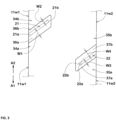
- FIG. 3 shows an enlarged top view of the first lateral sipe 21, and an enlarged top view of the second lateral sipe 22.
- FIG. 4 is an enlarged cross sectional view of the first lateral sipe 21 taken along line A-A of FIG. 2 .
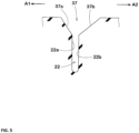
- FIG. 5 is an enlarged cross sectional view of the second lateral sipe 22 taken along line B-B in FIG. 2 .
- each of the first lateral sipes 21 has a first sipe wall 21a positioned on a first side A1 in the tire circumferential direction, and a second sipe wall 21b positioned on a second side A2 in the tire circumferential direction.
- sipe means a narrow groove having a width OF not more than 1.5 mm between two opposite side walls (in the case of FIG. 4 , first sipe wall 21a and second sipe wall 21b), inclusive of a cut having no substantial width.
- the sipe may be opened at the ground contacting top surface of the land portion via a chamfer portion as described later. Further, the sipe may include a bottom portion having an increased width formed radially inside the two opposite side walls.
- each of the first lateral sipes 21 opens at the ground contacting top surface 11s of the first land portion 11 via a chamfer portion 36.
- the chamfer portion 36 is formed by
- the width W1 of the first sloped surface 36a is larger than the width W2 of the second sloped surface 36b, when measured perpendicularly to the longitudinal direction of the first lateral sipe 21 in its top view.
- both edges of the first lateral sipe 21 are chamfered by the first sloped surface 36a and the second sloped surface 36b of the chamfer portion 36, uneven wear around the first lateral sipes 21 can be effectively suppressed.
- the width W1 of the first sloped surface 36a is larger than the width W2 of the second sloped surface 36b, the first sloped surface 36a can easily contact with the ground during acceleration or deceleration of the vehicle, and a large grip force can be exhibited, while suppressing a decrease in rubber volume due to the chamfering.
- an improvement in traction performance or braking performance on dry road surfaces can be obtained, while suppressing uneven wear.
- the total depth d1 of the first lateral sipe 21 including the chamfer portion 36 is, for example, set in a range from 70% to 90% of the depth of the circumferential groove 3.
- the total depth d1 is in a range from 2.0 to 2.5 times the depth d2 of the chamfer portion 37.
- the total depth d1 is the depth from the ground contacting top surface to the bottom of the sipe.
- the depth of the sipe means the total depth including the chamfer portion.
- the depth d2 of the chamfer portion 37 is 2.0 mm or less, preferably 1.0 to 2.0 mm.
- the opening width W5 (shown in FIG. 2 ) of the chamfer portion 36 is, for example, in a range from 2.5 to 4.5 mm.
- the first lateral sipe 21 is however, not limited to such configuration.
- the first lateral sipes 21 in this embodiment are inclined at an angle in a range from 30 to 40 degrees with respect to the tire axial direction.
- the first lateral sipes 21 each extend from the axially inner edge 11a and end within the ground contacting top surface 11s of the first land portion 11 to have a closed end 21e as shown in FIG. 2 .
- the first lateral sipes 21 in this embodiment end on the axially inside of the center position in the tire axial direction of the first land portion 11.
- the axial length L3 of each first lateral sipe 21 is, for example, set in a range from 25% to 40% of the axial width W6 of the ground contacting top surface 11s of the first land portion 11.
- Such first lateral sipes 21 can improve the dry performance while suppressing uneven wear.
- the width W1 of the first sloped surface 36a is constant over a range of not less than 70% of the first sipe wall 21a in the longitudinal direction of the sipe.
- the width W2 of the second sloped surface 36b is constant over a range of not less than 70% of the second sipe wall 21b in the longitudinal direction of the sipe.
- each of the width W1 and the width W2 is substantially constant over the entire range of the first lateral sipe 21 in the longitudinal direction.
- the width W1 of the first sloped surface 36a is in a range from 2.0 to 5.0 times, more preferably, 3.0 to 4.0 times the width W7 (shown in FIG. 4 ) between the first sipe wall 21a and the second sipe wall 21b.
- the width W7 is set in a range from 0.2 to 1.0 mm.
- Such first sloped surface 36a can enhance the dry performance and uneven wear resistance in a well-balanced manner.
- the angle ⁇ 1 of the first sloped surface 36a is, for example, set in a range from 40 to 60 degrees with respect to a normal line to the ground contacting top surface in the cross sectional view of the sipe 21 perpendicular to the longitudinal direction of the sipe 21 as shown in FIG. 4 .
- the width W1 of the first sloped surface 36a is preferably not less than 1.5 times, more preferably not less than 1.8 times, but preferably not more than 3.5 times, more preferably not more than 3.2 times the width W2 of the second sloped surface 36b.
- the angle ⁇ 2 of the second sloped surface 36b is, for example, set in a range from 20 to 40 degrees with respect to a normal line to the ground contacting top surface in the cross sectional view of the sipe 21 perpendicular to the longitudinal direction of the sipe 21 as shown in FIG. 4 .
- the difference between the angle ⁇ 1 and the angle ⁇ 2 is not more than 25 degrees.
- the first land portion 11 is provided with second lateral sipes 22 extending in the tire axial direction.
- the second lateral sipes 22 are inclined in the same direction as the first lateral sipes 21 with respect to the tire axial direction, and further, the inclination angle is also the same as the first lateral sipes 21.
- the second lateral sipes 22 each extend from the axially outer edge 11b and end within the ground contacting top surface 11s of the first land portion 11 to have a closed end 22e.
- the axial length L4 of each second lateral sipe 22 in this embodiment is set in a range from 25% to 40% of the axial width W6 of the ground contacting top surface 11s of the first land portion 11.
- the axial length L4 of the second lateral sipe 22 may be smaller than the axial length L3 of the first lateral sipe 21.
- the axial length L3 is, for example, not more than 130%, preferably in a range from 110% to 120% of the axial length L4.
- each of the second lateral sipes 22 has a first sipe wall 22a positioned on the first side A1 in the tire circumferential direction, and a second sipe wall 22b positioned on the second side A2 in the tire circumferential direction.
- Each of the second lateral sipes 22 opens at the ground contacting top surface 11s of the first land portion 11 via a chamfer portion 37.
- the chamfer portion 37 is, as shown in FIG. 5 , formed by
- the width W3 of the first sloped surface 37a of the chamfer portion 37 of the second lateral sipe 22 is constant over a range of 70% or more of the first sipe wall 22a in the longitudinal direction of the sipe.
- the width W4 of the second sloped surface 37b of the chamfer portion 37 of the second lateral sipe 22 is constant over a range of 70% or more of the second sipe wall 22b in the longitudinal direction of the sipe.
- the width W3 and the width W4 are each substantially constant over the entire length of the second lateral sipe 22.
- the above-described configuration of the second sloped surface 36b of the first lateral sipe 21 is applied to the first sloped surface 37a of the second lateral sipe 22. Also, the above-described configuration of the first sloped surface 36a of the first lateral sipe 21 is applied to the second sloped surface 37b of the second lateral sipe 22. Therefore, detailed descriptions of both sloped surfaces of the second lateral sipe 22 are omitted.
- FIG. 6 is a cross-sectional view taken along line C-C in FIG. 2 to show the cross section of the first lateral sipe 21 along its length direction.
- FIG. 7 is a cross-sectional view taken along line D-D in FIG. 2 to show the cross section of the second lateral sipe 22 along its length direction.
- the depth of the first lateral sipe 21 increases toward the closed end 21e to have a maximum depth d4.
- the depth d3 of the second lateral sipe 22 is substantially constant along its longitudinal direction.
- the maximum depth d4 is smaller than the depth d3, for example, set in a range from 70% to 90% of the depth d3.
- Such first lateral sipes 21 and second lateral sipes 22 help to improve the dry performance and wet performance in a well-balanced manner.
- the first lateral sipes 21 are shifted from the second lateral sipes 22 in the tire circumferential direction as shown in FIG. 2 .
- a virtual zone 41 (indicated by a fine dot pattern in FIG. 2 ) extended from each of the first lateral sipes 21 in the longitudinal direction thereof with the same width as the first lateral sipe 21, overlaps with none of the second lateral sipes 22.
- a virtual zone 42 (indicated by a fine dot pattern in FIG. 2 ) extended from each of the second lateral sipes 22 in the longitudinal direction thereof with the same width as the second lateral sipe 22, overlaps with none of the first lateral sipes 21.
- Such sipe arrangement helps to further improve the uneven wear resistance
- the second lateral sipes 22 are arranged at the same pitches in the tire circumferential direction as the first lateral sipes 21.
- each of the second lateral sipes 22 is positioned closely to one of the first lateral sipes 21 adjacent thereto on the second side A2 in the tire circumferential direction than one of the first lateral sipes 21 adjacent thereto on the first side A1 in the tire circumferential direction.
- the first sloped surface 36a of the first lateral sipe 21 and the second sloped surface 37b of the second lateral sipe 22 come closer to each other, thereby further improving the uneven wear resistance.
- the minimum distance L10 in the tire circumferential direction between the end of the first lateral sipe 21 at the axially inner edge 11a and the end of the second lateral sipe 22 at the axially outer edge 11b is preferably not more than 30%, more preferably not more than 25%, but preferably not less than 15% of one pitch length P1 in the tire circumferential direction of the first lateral sipes 21 or the second lateral sipes 22.
- the first land portion 11 in the present embodiment is provided with no grooves or sipes except for the first lateral sipes 21 and the second lateral sipes 22, so the first land portion 11 is continuous in the tire circumferential direction. Such first land portion 11 can further improve the dry performance.
- the second land portion 12 is provided with first shallow grooves 26.
- the first shallow grooves 26 in this example each extend from the first circumferential groove 6 and end to have a closed end 26e within the ground contacting top surface of the second land portion 12.
- the first shallow grooves 26 are inclined with respect to the tire axial direction in the same direction as the first lateral sipes 21 and the second lateral sipes 22.
- the angles of the first shallow grooves 26 with respect to the tire axial direction are, for example, set in a range from 30 to 40 degrees.
- the axial length L5 of each of the first shallow grooves 26 is, for example, set in a range from 40% to 60% of the axial width W8 of the ground contacting top surface of the second land portion 12. Preferably, the axial length L5 is greater than the axial length L3 of the first lateral sipes 21. Such first shallow grooves 26 help to improve the uneven wear resistance and wet performance.
- FIG. 8 is a cross-sectional view taken along line E-E in FIG. 2 to show a cross section of the first shallow groove 26 perpendicular to the longitudinal direction thereof.
- the depth d5 of the first shallow groove 26 is, for example, set in a range from 0.5 to 1.5 mm.
- the groove width W14 of the first shallow groove 26 is, for example, set in a range from 1.5 to 2.5 mm.
- the first shallow groove 26 has two groove walls 26w inclined relatively largely to have a V-shaped cross-sectional shape as shown in FIG. 8 .
- the angle ⁇ 3 between the two groove walls 26w in the cross section of the first shallow groove 26 is, for example, set in a range from 80 to 100 degrees.
- the groove walls 26w of such first shallow grooves 26 contact with the road surface, and the dry performance and wet performance are improved.
- a virtual zone 43 (indicated by a fine dot pattern in FIG. 2 ) extended from each of the first shallow grooves 26 in the longitudinal direction thereof with the same width as the first shallow groove 26, preferably overlaps with one of the first lateral sipes 21 in the plan view of the tread portion.
- Such first shallow grooves 26 can further improve the dry performance and wet performance.
- the third land portion 13 is provided with second shallow grooves 27.
- the second shallow grooves 27 in the present embodiment each extend from the second circumferential groove 7 and end to have a closed end 27e within the ground contacting top surface of the third land portion 13.
- the axial length L6 of each second shallow groove 27 is set in a range from 5% to 15% of the axial width W9 of the ground contacting top surface of the third land portion 13.
- the axial length L6 is less than the axial length L4 of the second lateral sipes 22.
- Such second shallow grooves 27 can improve the dry performance while suppressing uneven wear of the third land portion 13.
- the configuration of the first shallow groove 26 with respect to of the cross section described above with reference to FIG. 8 is applied to the cross section of the second shallow groove 27. Therefore, description of the cross section of the second shallow groove 27 is omitted.
- the second shallow grooves 27 are sifted from the second lateral sipes 22 in the tire circumferential direction as shown in FIG. 2 . It is preferable that a virtual zone 44 (indicated by a fine dot pattern in FIG. 2 ) extended from each of the second lateral sipes 22 in the longitudinal direction thereof with the same width as the second lateral sipe 22, overlaps with none of the second shallow grooves 27 in the plan view of the tread portion as shown in FIG. 2 . Thereby, the uneven wear resistance may be further improved.
- the third land portion 13 is further provided with first lateral grooves 31.
- the first lateral groove 31 in this embodiment extends across the inboard tread edge T2 and has a closed end 31e within the ground contacting top surface of the third land portion 13. Such first lateral grooves 31 can improve the uneven wear resistance and wet performance.
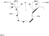
- FIG. 9 is a cross-sectional view taken along line F-F of FIG. 2 .
- the first lateral groove 31 is provided with a chamfer portion 38.
- the chamfer portion 38 comprises a small sloped surface 38a extending between one of the groove walls 31w of the first lateral groove 31 and the ground contacting top surface of the third land portion 13, and a large sloped surface 38b extending between the other of the groove walls 31w of the first lateral groove 31 and the ground contacting top surface of the third land portion 13.
- the large sloped surface 38b has a chamfer width W12
- the small sloped surface 38a has a chamfer width W11 smaller than the chamfer width W12.
- the chamfer width W11 is set in a range from 40% to 60% of the chamfer width W12.
- the small sloped surface 38a is positioned on the first side A1 in the tire circumferential direction with respect to the large sloped surface 38b.
- FIG. 10 shows a partial top view of the fourth land portion 14 and that of the fifth land portion 15.
- the fourth land portion 14 is provided with third shallow grooves 28 and third lateral sipes 23.
- Each of the third shallow grooves 28 in the present embodiment extends from the third circumferential groove 8 and ends to have a closed end 28e within the ground contacting top surface of the fourth land portion 14.
- the axial length L7 of each third shallow groove 28 is, for example, set in a range from 15% to 25% of the axial width W13 of the ground contacting top surface of the fourth land portion 14.
- the axial length L7 is smaller than the axial length L3 of the first lateral sipes 21.
- Such third shallow grooves 28 can improve the dry performance and wet performance while suppressing uneven wear of the fourth land portion 14.
- Each of the third lateral sipes 23 in this embodiment extends from the fourth circumferential groove 9 and ends to have a closed end 23e within the ground contacting top surface of the fourth land portion 14.
- the axial length L8 of each third lateral sipe 23 is set in a range from 40% to 60% of the axial width W13 of the ground contacting top surface of the fourth land portion 14.
- the axial length L8 is greater than the axial length L3 (shown in FIG. 2 ) of the first lateral sipe 21.
- Such third lateral sipes 23 help to improve the dry performance and wet performance in a well-balanced manner.
- the third lateral sipe 23 opens at the ground contacting top surface via a chamfer portion 39.
- the chamfer portion 39 of the third lateral sipe 23 comprises two sloped surfaces 40 extending between the respective sipe walls and the ground contacting top surface of the fourth land portion 14.
- the width of each of the sloped surfaces 40 (46 and 47) measured perpendicularly to the longitudinal direction of the third lateral sipe 23 is continuously increases toward the fourth circumferential groove 9.
- the third lateral sipe 23 having such sloped surfaces 40 can effectively guide a water film existing between the fourth land portion 14 and a wet road surface, toward the fourth circumferential groove 9, and helps to improve the wet performance.
- the area of one 46 of the two sloped surfaces 40 is larger than the area of the other 47 of the two sloped surfaces 40.
- the sloped surface 46 with the lager area is positioned on the first side A1 in the tire circumferential direction with respect to the sloped surface 47 with the smaller area.
- Such arrangement of the sloped surfaces 40 of the third lateral sipes 23 can improve the braking performance and the traction performance on dry road surfaces in a well-balanced manner in cooperation with the first lateral sipes 21 and second lateral sipes 22.
- the fifth land portion 15 is provided with second lateral grooves 32.
- the second lateral grooves 32 in this embodiment extend axially outwardly from the fourth circumferential groove 9 beyond the outboard tread edge T1. Such second lateral grooves 32 can improve the wet performance.
- the second lateral groove 32 has a cross section similar to that shown in FIG. 9 , and the second lateral groove 32 has a chamfer portion 50 comprising a small sloped surface 50a and a large sloped surface 50b positioned on the first side A1 of the small sloped surface 50a. Accordingly, the positional relationship between the small sloped surface 50a and the large sloped surface 50b of the second lateral groove 32 is reverse of the positional relationship between the small sloped surface 38a and the large sloped surface 38b of the first lateral groove 31. As a result, the traction performance and the braking performance on dry road surfaces are improved in a well-balanced manner.
- pneumatic tires of size 235/35ZR19 were experimentally manufactured as test tires (working examples Ex.1-Ex.9 and comparative example Ref.).
- first lateral sipes (a), second lateral sipes (b) and third lateral sipes (c) were not provided with chamfer portions as shown in FIG. 11 .
- the comparative example was substantially the same as the working examples.
- test tires were tested for the braking performance and traction performance on dry road surfaces as well as uneven wear resistance as follows, using a test car (2000cc, 4WD passenger car) in which the test tires were mounted on the four wheels and inflated to 260 kPa.
- the remaining height of the worn first land portion was measured around the first lateral sipes.
- each of the working examples exhibited excellent uneven wear resistance. Further, it could be confirmed that the working examples were improved in both braking performance and traction performance on dry road surfaces, owing to the first lateral sipes and the second lateral sipes between which the positional relationship of the small sloped surface and the large sloped surface was reversed.
- the present invention is as follows.
- Invention 2 The tire according to Invention 1, wherein the width W1 of the first sloped surface is constant over at least 70% of the first sipe wall in the longitudinal direction of the sipe.
- Invention 3 The tire according to Invention 1 or 2, wherein the width W1 of the first sloped surface is in a range from 1.5 to 3.5 times the width W2 of the second sloped surface.
- Invention 4 The tire according to Invention 1, 2 or 3, wherein
- Invention 5 The tire according to any one of Inventions 1 to 4, wherein
- Invention 6 The tire according to Invention 5, wherein
- Invention 7 The tire according to any one of Inventions 4 to 6, wherein a maximum depth of the second lateral sipes is less than a maximum depth of the first lateral sipes.
- Invention 8 The tire according to any one of Inventions 1 to 7, wherein
- Invention 9 The tire according to Invention 8, wherein
- Invention 10 The tire according to Invention 8 or 9, wherein
- Invention 11 The tire according to any one of Inventions 8 to 10, wherein
Landscapes
- Engineering & Computer Science (AREA)
- Mechanical Engineering (AREA)
- Tires In General (AREA)
Abstract
Description
- The present invention relates to a tire.
- Patent Document 1 below discloses a tire in which steering stability on dry road surfaces and wet cornering performance are improved by improving lateral grooves and sipes provided in a first land portion.
Patent Document 1:Japanese Patent Application Publication No. 2015-137015 - In recent years, the performance of vehicles has progressed, and like vehicles, tires are required to be further improved in braking performance and traction performance on dry road surfaces. Further, tires are required to be suppressed in uneven wear.
- The present invention was made in view of the circumstances as described above, and a primary objective of the present invention is to provide a tire of which braking performance and traction performance on dry road surfaces can be improved while suppressing uneven wear.
- According to the present invention, a tire comprises:
- a tread portion including a first land portion having a first edge and a second edge both extending in the tire circumferential direction, and a ground contacting top surface formed therebetween,
- the first land portion provided with first lateral sipes extending in a tire axial direction, and
- the first lateral sipes each having a first sipe wall and a second sipe wall which are respectively located on a first side and a second side in the tire circumferential direction,
wherein - each of the first lateral sipes opens at the ground contacting top surface of the first land portion via a chamfer portion,
- the chamfer portion comprises a first sloped surface continued from the first sipe wall, and a second sloped surface continued from the second sipe wall, and
- in a plan view of the first land portion, a width W1 of the first sloped surface is greater than a width W2 of the second sloped surface.
- Therefore, in the tire according to the present invention, by adopting the above configuration of the first lateral sipe, the braking performance and traction performance on dry road surfaces can be improved, while suppressing uneven wear.
-
-
FIG. 1 is a developed partial view of a tread portion of a tire as an embodiment of the present invention. -
FIG. 2 is an enlarged view showing a first land portion, a second land portion and a third land portion shown inFIG. 1 . -
FIG. 3 is an enlarged view showing first lateral sipes and second lateral sipes shown inFIG. 2 . -
FIG. 4 is a cross-sectional view taken along line A-A ofFIG. 2 . -
FIG. 5 is a cross-sectional view taken along line B-B ofFIG. 2 . -
FIG. 6 is a cross-sectional view taken along line C-C ofFIG. 2 . -
FIG. 7 is a cross-sectional view taken along line D-D ofFIG. 2 . -
FIG. 8 is a cross-sectional view taken along line E-E ofFIG. 2 . -
FIG. 9 is a cross-sectional view taken along line F-F ofFIG. 2 . -
FIG. 10 is an enlarged view showing a fourth land portion and a fifth land portion shown inFIG. 1 . -
FIG. 11 is a developed partial view of a tread portion of a comparative example. - The present invention may be applied to various tires, e.g. pneumatic tires and non-pneumatic tires for various vehicles, e.g. passenger cars, heavy-duty vehicles such as trucks and busses, and the like. In particular, the present invention is suitably applied to a pneumatic tire for passenger cars.
- Taking a pneumatic tire for passenger cars as an example, an embodiment of the present invention will be described in detail in conjunction with accompanying drawings.
-
FIG. 1 is a developed partial view of atread portion 2 of a pneumatic tire 1 as an embodiment of the present invention. - As well known in the art, a pneumatic tire comprises a
tread portion 2 whose radially outer surface defines the tread, a pair of axially spaced bead portions mounted on rim seats, a pair of sidewall portions extending between the tread edges and the bead portions, a carcass extending between the bead portions through the tread portion and the sidewall portions, and a tread reinforcing belt disposed radially outside the carcass in the tread portion. - In the present embodiment, the mounting direction of the tire 1 to a vehicle is specified. That is, the
tread portion 2 has an outboard tread edge T1 to be positioned away from the center of the vehicle body, and an inboard tread edge T2 to be positioned close to the center of the vehicle body.
For example, a sidewall portion (not shown) of the tire to be located outboard when the tire installed on the vehicle is provided with an indication representing "outside", and a sidewall portion to be located inboard is provided with an indication representing "inside". - The tread edges T1 and T2 are the axial outermost edges of the ground contacting patch of the tire which occurs when the tire under its normal state is contacted with a flat horizontal surface at a camber angle of 0 degrees and loaded with the normal tire load for the tire.
- When the tire 1 is a pneumatic tire for which various standards have been established, the normal state of the tire 1 is such that the tire 1 is mounted on a normal rim, and inflated to a normal pressure, but loaded with no tire load.
- When the tire 1 is a pneumatic tire or non-pneumatic tire for which various standards are not yet established, the normal state of the tire 1 is such that the tire is put under a standard usage condition according to the purpose of use of the tire, but not yet attached to the vehicle and loaded with no tire load.
- In this application including specification and claims, various dimensions, positions and the like of the tire refer to those under the normal state unless otherwise noted.
- The above-mentioned normal rim is a wheel rim officially approved or recommended for the tire by the standardization organization on which the tire is based, i.e. JATMA (Japan and Asia), T&RA (North America), ETRTO (Europe), TRAA (Australia), STRO (Scandinavia), ALAPA (Latin America), ITTAC (India) and the like which are effective in the area where the tire is manufactured, sold or used.
- The above-mentioned normal pressure is the maximum air pressure officially approved or recommended for the tire by the standardization organization on which the tire is based, for example, the "maximum air pressure" in JATMA, the maximum pressure given in the "Tire Load Limits at Various Cold Inflation Pressures" table in TRA, and the "Inflation Pressure" in
ETRTO. - When the tire 1 is a pneumatic tire for which various standards have been established, the normal tire load is the maximum tire load officially approved or recommended for the tire by the same standardization organization and specified in the Air-pressure/Maximum-load Table or similar list, for example, the "maximum air pressure" in JATMA, the "Inflation Pressure" in ETRTO, the maximum pressure given in the "Tire Load Limits at Various Cold Inflation Pressures" table in TRA or the like.
- When the tire 1 is a pneumatic tire or non-pneumatic tire for which various standards are not yet established, the normal tire load is the maximum tire load recommended for the tire by the tire manufacturer.
- The
tread portion 2 is provided, between the outboard tread edge T1 and the inboard tread edge T2, withcircumferential grooves 3 continuously extending in the tire circumferential direction, and thereby, thetread portion 2 is axially divided intoannular land portions 4.
In this embodiment, the number of thecircumferential grooves 3 is four, and the number of theland portions 4 is accordingly five.
The present invention is however, not limited thereto. For example, thetread portion 2 may be axially divided into fourland portions 4 by threecircumferential grooves 3. - In this embodiment, the
circumferential grooves 3 include an axially inner firstcircumferential groove 6 and an axially outer secondcircumferential groove 7 which are disposed between the tire equator C and the inboard tread edge T2, and
an axially inner thirdcircumferential groove 8 and an axially outer fourthcircumferential groove 9 which are disposed between the tire equator C and the outboard tread edge T1. - It is preferable that an axial distance L1 from the tire equator C to the widthwise centerline of the first
circumferential groove 6 is 5% to 15% of the tread width TW, and
an axial distance L1 from the tire equator C to the widthwise centerline of the thirdcircumferential groove 8 is 5% to 15% of the tread width TW. - It is preferable that an axial distance L2 from the tire equator C to the widthwise centerline of the second
circumferential groove 7 is 25% to 35% of the tread width TW, and an axial distance L2 from the tire equator C to the widthwise centerline of the fourthcircumferential groove 9 is 25% to 35% of the tread width TW. - Here, the tread width TW is the distance in the tire axial direction between the outboard tread edge T1 and the inboard tread edge T2 measured under the normal state of the tire.
- In the present embodiment, each of the
circumferential grooves 3 is a straight groove parallel with the tire circumferential direction. However, thecircumferential grooves 3 may be zigzag or wavy grooves alone or in combination with straight groove(s). - It is preferable that the groove width Wa of each of the
circumferential grooves 3 is at least 3 mm. It is preferable that the groove width Wa is 2.0% to 8.0% of the tread width TW.
In the present embodiment, the groove width Wa of the fourthcircumferential groove 9 is smallest among thecircumferential grooves 3.
The present invention is however, not limited to such groove width arrangement. - In the present embodiment, the
land portions 4 are:
afirst land portion 11 between the first and secondcircumferential grooves second land portion 12 between the first and thirdcircumferential grooves third land portion 13 axially outward of the secondcircumferential groove 7; afourth land portion 14 between the third and fourthcircumferential grooves fifth land portion 15 axially outward of the fourthcircumferential groove 9.
In this embodiment, thesecond land portion 12 includes the tire equator C within the width; thethird land portion 13 includes the inboard tread edge T2; and thefifth land portion 15 includes the outboard tread edge T1. - As shown in
FIG. 2 , thefirst land portion 11 has - an axially
inner edge 11a and an axiallyouter edge 11b which extend in the tire circumferential direction, - a ground contacting
top surface 11s extending therebetween, - an axially inner side wall 11w1 extending radially inwardly from the axially
inner edge 11a, and - an axially outer side wall 11w2 extending radially inwardly from the axially
outer edge 11b. - The
first land portion 11 is provided with firstlateral sipes 21 extending in the tire axial direction.
In the present embodiment, thefirst land portion 11 is further provided with secondlateral sipes 22 extending in the tire axial direction. -
FIG. 3 shows an enlarged top view of thefirst lateral sipe 21, and an enlarged top view of thesecond lateral sipe 22.
FIG. 4 is an enlarged cross sectional view of thefirst lateral sipe 21 taken along line A-A ofFIG. 2 .
FIG. 5 is an enlarged cross sectional view of thesecond lateral sipe 22 taken along line B-B inFIG. 2 . - As shown in
FIG. 4 , each of the firstlateral sipes 21 has afirst sipe wall 21a positioned on a first side A1 in the tire circumferential direction, and asecond sipe wall 21b positioned on a second side A2 in the tire circumferential direction. - Here, the term "sipe" means a narrow groove having a width OF not more than 1.5 mm between two opposite side walls (in the case of
FIG. 4 ,first sipe wall 21a andsecond sipe wall 21b), inclusive of a cut having no substantial width. - The sipe may be opened at the ground contacting top surface of the land portion via a chamfer portion as described later. Further, the sipe may include a bottom portion having an increased width formed radially inside the two opposite side walls.
- As shown in
FIG. 4 , each of the firstlateral sipes 21 opens at the ground contactingtop surface 11s of thefirst land portion 11 via achamfer portion 36. - The
chamfer portion 36 is formed by - a first
sloped surface 36a extending from the ground contactingtop surface 11s to thefirst sipe wall 21a, and - a second
sloped surface 36b extending from the ground contactingtop surface 11s to thesecond sipe wall 21b. - As shown in
FIG. 3 , the width W1 of the firstsloped surface 36a is larger than the width W2 of the secondsloped surface 36b, when measured perpendicularly to the longitudinal direction of thefirst lateral sipe 21 in its top view.
Thereby, the tire 1 according to the present invention can be improved in braking performance and traction performance on dry road surfaces (hereinafter, these performances are comprehensively referred to as "dry performance"), while suppressing uneven wear as explained below. - Since both edges of the
first lateral sipe 21 are chamfered by the firstsloped surface 36a and the secondsloped surface 36b of thechamfer portion 36, uneven wear around the firstlateral sipes 21 can be effectively suppressed. Further, since the width W1 of the firstsloped surface 36a is larger than the width W2 of the secondsloped surface 36b, the firstsloped surface 36a can easily contact with the ground during acceleration or deceleration of the vehicle, and a large grip force can be exhibited, while suppressing a decrease in rubber volume due to the chamfering. Thereby, in the present invention, an improvement in traction performance or braking performance on dry road surfaces can be obtained, while suppressing uneven wear. - As shown in
FIG. 4 , the total depth d1 of thefirst lateral sipe 21 including thechamfer portion 36 is, for example, set in a range from 70% to 90% of the depth of thecircumferential groove 3. Preferably, the total depth d1 is in a range from 2.0 to 2.5 times the depth d2 of thechamfer portion 37. The total depth d1 is the depth from the ground contacting top surface to the bottom of the sipe. Hereinafter, unless otherwise specified, the depth of the sipe means the total depth including the chamfer portion.
The depth d2 of thechamfer portion 37 is 2.0 mm or less, preferably 1.0 to 2.0 mm.
The opening width W5 (shown inFIG. 2 ) of thechamfer portion 36 is, for example, in a range from 2.5 to 4.5 mm.
Thefirst lateral sipe 21 is however, not limited to such configuration. - As shown in
FIG. 2 , the firstlateral sipes 21 in this embodiment are inclined at an angle in a range from 30 to 40 degrees with respect to the tire axial direction.
Between thefirst sipe wall 21a to which the firstsloped surface 36a having the larger width W1 is connected, and the axially inner side wall 11w1 of thefirst land portion 11, there is formed an obtuseangled corner 34a in the top view of thefirst land portion 11 as shown inFIG. 3 .
Between thesecond sipe wall 21b to which the secondsloped surface 36b having the smaller width W2 is connected, and the axially inner side wall 11w1 of thefirst land portion 11, there is formed an acuteangled corner 34b in the top view of thefirst land portion 11 as shown inFIG. 3 . - Preferably, the first
lateral sipes 21 each extend from the axiallyinner edge 11a and end within the ground contactingtop surface 11s of thefirst land portion 11 to have aclosed end 21e as shown inFIG. 2 .
The firstlateral sipes 21 in this embodiment end on the axially inside of the center position in the tire axial direction of thefirst land portion 11.
The axial length L3 of eachfirst lateral sipe 21 is, for example, set in a range from 25% to 40% of the axial width W6 of the ground contactingtop surface 11s of thefirst land portion 11.
Such firstlateral sipes 21 can improve the dry performance while suppressing uneven wear. - As shown in
FIG. 3 , the width W1 of the firstsloped surface 36a is constant over a range of not less than 70% of thefirst sipe wall 21a in the longitudinal direction of the sipe. Also, the width W2 of the secondsloped surface 36b is constant over a range of not less than 70% of thesecond sipe wall 21b in the longitudinal direction of the sipe.
Preferably, each of the width W1 and the width W2 is substantially constant over the entire range of thefirst lateral sipe 21 in the longitudinal direction. As a result, the above-described effects can be reliably exhibited. - Preferably, the width W1 of the first
sloped surface 36a is in a range from 2.0 to 5.0 times, more preferably, 3.0 to 4.0 times the width W7 (shown inFIG. 4 ) between thefirst sipe wall 21a and thesecond sipe wall 21b.
For example, the width W7 is set in a range from 0.2 to 1.0 mm.
Such firstsloped surface 36a can enhance the dry performance and uneven wear resistance in a well-balanced manner.
From a similar point of view, the angle θ1 of the firstsloped surface 36a is, for example, set in a range from 40 to 60 degrees with respect to a normal line to the ground contacting top surface in the cross sectional view of thesipe 21 perpendicular to the longitudinal direction of thesipe 21 as shown inFIG. 4 . - As shown in
FIG. 3 , the width W1 of the firstsloped surface 36a is preferably not less than 1.5 times, more preferably not less than 1.8 times, but preferably not more than 3.5 times, more preferably not more than 3.2 times the width W2 of the secondsloped surface 36b. As a result, the dry performance and uneven wear resistance are improved in a well-balanced manner.
From a similar point of view, the angle θ2 of the secondsloped surface 36b is, for example, set in a range from 20 to 40 degrees with respect to a normal line to the ground contacting top surface in the cross sectional view of thesipe 21 perpendicular to the longitudinal direction of thesipe 21 as shown inFIG. 4 . - Preferably, the difference between the angle θ1 and the angle θ2 is not more than 25 degrees.
- In the present embodiment, as shown in
FIG. 2 , thefirst land portion 11 is provided with secondlateral sipes 22 extending in the tire axial direction. In this embodiment, the secondlateral sipes 22 are inclined in the same direction as the firstlateral sipes 21 with respect to the tire axial direction, and further, the inclination angle is also the same as the firstlateral sipes 21. Between thesecond sipe wall 22b to which the secondsloped surface 37b having a larger width W4 is connected, and the axially outer side wall 11w2 of thefirst land portion 11, there is formed an obtuseangled corner 35b in the top view of thefirst land portion 11.
Between thefirst sipe wall 22a to which the firstsloped surface 37a having a smaller width W3 is connected, and the axially outer side wall 11w2 of thefirst land portion 11, there is formed an acuteangled corner 35a in the top view of thefirst land portion 11. - In this embodiment, as shown in
FIG. 2 , the secondlateral sipes 22 each extend from the axiallyouter edge 11b and end within the ground contactingtop surface 11s of thefirst land portion 11 to have aclosed end 22e. The axial length L4 of eachsecond lateral sipe 22 in this embodiment is set in a range from 25% to 40% of the axial width W6 of the ground contactingtop surface 11s of thefirst land portion 11. - As another example, the axial length L4 of the
second lateral sipe 22 may be smaller than the axial length L3 of thefirst lateral sipe 21.
In this case, the axial length L3 is, for example, not more than 130%, preferably in a range from 110% to 120% of the axial length L4.
Thereby, uneven wear of thefirst land portion 11 in an axiallyinner edge 11a side portion may be suppressed. - As shown in
FIG. 5 , each of the secondlateral sipes 22 has afirst sipe wall 22a positioned on the first side A1 in the tire circumferential direction, and asecond sipe wall 22b positioned on the second side A2 in the tire circumferential direction.
Each of the secondlateral sipes 22 opens at the ground contactingtop surface 11s of thefirst land portion 11 via achamfer portion 37. - The
chamfer portion 37 is, as shown inFIG. 5 , formed by - a first
sloped surface 37a extending from thefirst sipe wall 22a to the ground contactingtop surface 11s , and - a second
sloped surface 37b extending from thesecond sipe wall 22b to the ground contactingtop surface 11s. - The width W3 of the first
sloped surface 37a of thechamfer portion 37 of thesecond lateral sipe 22 is constant over a range of 70% or more of thefirst sipe wall 22a in the longitudinal direction of the sipe.
The width W4 of the secondsloped surface 37b of thechamfer portion 37 of thesecond lateral sipe 22 is constant over a range of 70% or more of thesecond sipe wall 22b in the longitudinal direction of the sipe.
Preferably, the width W3 and the width W4 are each substantially constant over the entire length of thesecond lateral sipe 22. Thereby, the above-described effects can be reliably exhibited. - The above-described configuration of the second
sloped surface 36b of thefirst lateral sipe 21 is applied to the firstsloped surface 37a of thesecond lateral sipe 22.
Also, the above-described configuration of the firstsloped surface 36a of thefirst lateral sipe 21 is applied to the secondsloped surface 37b of thesecond lateral sipe 22.
Therefore, detailed descriptions of both sloped surfaces of thesecond lateral sipe 22 are omitted. -
FIG. 6 is a cross-sectional view taken along line C-C inFIG. 2 to show the cross section of thefirst lateral sipe 21 along its length direction.
FIG. 7 is a cross-sectional view taken along line D-D inFIG. 2 to show the cross section of thesecond lateral sipe 22 along its length direction.
As shown inFIG. 6 , the depth of thefirst lateral sipe 21 increases toward theclosed end 21e to have a maximum depth d4.
As shown inFIG. 7 , the depth d3 of thesecond lateral sipe 22 is substantially constant along its longitudinal direction.
Preferably, the maximum depth d4 is smaller than the depth d3, for example, set in a range from 70% to 90% of the depth d3.
Such firstlateral sipes 21 and secondlateral sipes 22 help to improve the dry performance and wet performance in a well-balanced manner. - Preferably, the first
lateral sipes 21 are shifted from the secondlateral sipes 22 in the tire circumferential direction as shown inFIG. 2 . - Preferably, in the top view of the
first land portion 11 as shown inFIG. 2 , a virtual zone 41 (indicated by a fine dot pattern inFIG. 2 ) extended from each of the firstlateral sipes 21 in the longitudinal direction thereof with the same width as thefirst lateral sipe 21, overlaps with none of the secondlateral sipes 22.
Similarly, it is preferable that a virtual zone 42 (indicated by a fine dot pattern inFIG. 2 ) extended from each of the secondlateral sipes 22 in the longitudinal direction thereof with the same width as thesecond lateral sipe 22, overlaps with none of the firstlateral sipes 21.
Such sipe arrangement helps to further improve the uneven wear resistance - In the present embodiment, the second
lateral sipes 22 are arranged at the same pitches in the tire circumferential direction as the firstlateral sipes 21. - In the present embodiment, each of the second
lateral sipes 22 is positioned closely to one of the firstlateral sipes 21 adjacent thereto on the second side A2 in the tire circumferential direction than one of the firstlateral sipes 21 adjacent thereto on the first side A1 in the tire circumferential direction.
As a result, the firstsloped surface 36a of thefirst lateral sipe 21 and the secondsloped surface 37b of thesecond lateral sipe 22 come closer to each other, thereby further improving the uneven wear resistance. - In the present embodiment, the minimum distance L10 in the tire circumferential direction between the end of the
first lateral sipe 21 at the axiallyinner edge 11a and the end of thesecond lateral sipe 22 at the axiallyouter edge 11b is preferably not more than 30%, more preferably not more than 25%, but preferably not less than 15% of one pitch length P1 in the tire circumferential direction of the firstlateral sipes 21 or the secondlateral sipes 22. - It is preferable that the
first land portion 11 in the present embodiment is provided with no grooves or sipes except for the firstlateral sipes 21 and the secondlateral sipes 22, so thefirst land portion 11 is continuous in the tire circumferential direction. Suchfirst land portion 11 can further improve the dry performance. - The
second land portion 12 is provided with firstshallow grooves 26. The firstshallow grooves 26 in this example each extend from the firstcircumferential groove 6 and end to have aclosed end 26e within the ground contacting top surface of thesecond land portion 12.
The firstshallow grooves 26 are inclined with respect to the tire axial direction in the same direction as the firstlateral sipes 21 and the secondlateral sipes 22.
The angles of the firstshallow grooves 26 with respect to the tire axial direction are, for example, set in a range from 30 to 40 degrees. - The axial length L5 of each of the first
shallow grooves 26 is, for example, set in a range from 40% to 60% of the axial width W8 of the ground contacting top surface of thesecond land portion 12. Preferably, the axial length L5 is greater than the axial length L3 of the firstlateral sipes 21.
Such firstshallow grooves 26 help to improve the uneven wear resistance and wet performance. -
FIG. 8 is a cross-sectional view taken along line E-E inFIG. 2 to show a cross section of the firstshallow groove 26 perpendicular to the longitudinal direction thereof.
The depth d5 of the firstshallow groove 26 is, for example, set in a range from 0.5 to 1.5 mm. The groove width W14 of the firstshallow groove 26 is, for example, set in a range from 1.5 to 2.5 mm.
Preferably, the firstshallow groove 26 has twogroove walls 26w inclined relatively largely to have a V-shaped cross-sectional shape as shown inFIG. 8 . The angle θ3 between the twogroove walls 26w in the cross section of the firstshallow groove 26 is, for example, set in a range from 80 to 100 degrees.
For example, when the second land portion is deformed due to the increased ground contact pressure during cornering, thegroove walls 26w of such firstshallow grooves 26 contact with the road surface, and the dry performance and wet performance are improved. - As shown in
FIG. 2 , a virtual zone 43 (indicated by a fine dot pattern inFIG. 2 ) extended from each of the firstshallow grooves 26 in the longitudinal direction thereof with the same width as the firstshallow groove 26, preferably overlaps with one of the firstlateral sipes 21 in the plan view of the tread portion. Such firstshallow grooves 26 can further improve the dry performance and wet performance. - The
third land portion 13 is provided with secondshallow grooves 27.
The secondshallow grooves 27 in the present embodiment each extend from the secondcircumferential groove 7 and end to have aclosed end 27e within the ground contacting top surface of thethird land portion 13.
The axial length L6 of each secondshallow groove 27 is set in a range from 5% to 15% of the axial width W9 of the ground contacting top surface of thethird land portion 13. Preferably, the axial length L6 is less than the axial length L4 of the secondlateral sipes 22.
Such secondshallow grooves 27 can improve the dry performance while suppressing uneven wear of thethird land portion 13. - The configuration of the first
shallow groove 26 with respect to of the cross section described above with reference toFIG. 8 , is applied to the cross section of the secondshallow groove 27. Therefore, description of the cross section of the secondshallow groove 27 is omitted. - It is preferable that the second
shallow grooves 27 are sifted from the secondlateral sipes 22 in the tire circumferential direction as shown inFIG. 2 . It is preferable that a virtual zone 44 (indicated by a fine dot pattern inFIG. 2 ) extended from each of the secondlateral sipes 22 in the longitudinal direction thereof with the same width as thesecond lateral sipe 22, overlaps with none of the secondshallow grooves 27 in the plan view of the tread portion as shown inFIG. 2 . Thereby, the uneven wear resistance may be further improved. - In the present embodiment, the
third land portion 13 is further provided with firstlateral grooves 31. - The first
lateral groove 31 in this embodiment extends across the inboard tread edge T2 and has aclosed end 31e within the ground contacting top surface of thethird land portion 13. Such firstlateral grooves 31 can improve the uneven wear resistance and wet performance. -
FIG. 9 is a cross-sectional view taken along line F-F ofFIG. 2 .
As shown, the firstlateral groove 31 is provided with achamfer portion 38. Thechamfer portion 38 comprises a small slopedsurface 38a extending between one of thegroove walls 31w of the firstlateral groove 31 and the ground contacting top surface of thethird land portion 13, and a large slopedsurface 38b extending between the other of thegroove walls 31w of the firstlateral groove 31 and the ground contacting top surface of thethird land portion 13.
The largesloped surface 38b has a chamfer width W12, and the small slopedsurface 38a has a chamfer width W11 smaller than the chamfer width W12. For example, the chamfer width W11 is set in a range from 40% to 60% of the chamfer width W12.
The smallsloped surface 38a is positioned on the first side A1 in the tire circumferential direction with respect to the large slopedsurface 38b.
By arranging the sloped surfaces in this way, the traction performance and braking performance on dry road surfaces can be improved in a well-balanced manner. -
FIG. 10 shows a partial top view of thefourth land portion 14 and that of thefifth land portion 15. - As shown, the
fourth land portion 14 is provided with thirdshallow grooves 28 and thirdlateral sipes 23. - Each of the third
shallow grooves 28 in the present embodiment extends from the thirdcircumferential groove 8 and ends to have aclosed end 28e within the ground contacting top surface of thefourth land portion 14. The axial length L7 of each thirdshallow groove 28 is, for example, set in a range from 15% to 25% of the axial width W13 of the ground contacting top surface of thefourth land portion 14. Preferably, the axial length L7 is smaller than the axial length L3 of the firstlateral sipes 21.
Such thirdshallow grooves 28 can improve the dry performance and wet performance while suppressing uneven wear of thefourth land portion 14. - The configuration of the cross section of the first
shallow groove 26 described above with reference toFIG. 8 is applied to the cross section of the thirdshallow groove 28.. This, redundant descriptions of the cross section of the thirdshallow groove 28 are omitted. - Each of the third
lateral sipes 23 in this embodiment extends from the fourthcircumferential groove 9 and ends to have aclosed end 23e within the ground contacting top surface of thefourth land portion 14.
The axial length L8 of eachthird lateral sipe 23 is set in a range from 40% to 60% of the axial width W13 of the ground contacting top surface of thefourth land portion 14. Preferably, the axial length L8 is greater than the axial length L3 (shown inFIG. 2 ) of thefirst lateral sipe 21.
Such thirdlateral sipes 23 help to improve the dry performance and wet performance in a well-balanced manner. - The
third lateral sipe 23 opens at the ground contacting top surface via achamfer portion 39.
Thechamfer portion 39 of thethird lateral sipe 23 comprises two slopedsurfaces 40 extending between the respective sipe walls and the ground contacting top surface of thefourth land portion 14.
As shown inFIG. 10 , in the top view of thefourth land portion 14, the width of each of the sloped surfaces 40 (46 and 47) measured perpendicularly to the longitudinal direction of thethird lateral sipe 23, is continuously increases toward the fourthcircumferential groove 9.
Thethird lateral sipe 23 having such slopedsurfaces 40 can effectively guide a water film existing between thefourth land portion 14 and a wet road surface, toward the fourthcircumferential groove 9, and helps to improve the wet performance. - Preferably, the area of one 46 of the two
sloped surfaces 40 is larger than the area of the other 47 of the twosloped surfaces 40. The slopedsurface 46 with the lager area is positioned on the first side A1 in the tire circumferential direction with respect to the slopedsurface 47 with the smaller area.
Such arrangement of the sloped surfaces 40 of the thirdlateral sipes 23 can improve the braking performance and the traction performance on dry road surfaces in a well-balanced manner in cooperation with the firstlateral sipes 21 and secondlateral sipes 22. - The
fifth land portion 15 is provided with secondlateral grooves 32. The secondlateral grooves 32 in this embodiment extend axially outwardly from the fourthcircumferential groove 9 beyond the outboard tread edge T1. Such secondlateral grooves 32 can improve the wet performance. - The configuration of the cross section of the first
lateral groove 31 described above with reference toFIG. 9 is applied to the cross section of the secondlateral groove 32. Namely, the secondlateral groove 32 has a cross section similar to that shown inFIG. 9 , and the secondlateral groove 32 has achamfer portion 50 comprising a small slopedsurface 50a and a large slopedsurface 50b positioned on the first side A1 of the small slopedsurface 50a. Accordingly, the positional relationship between the small slopedsurface 50a and the large slopedsurface 50b of the secondlateral groove 32 is reverse of the positional relationship between the small slopedsurface 38a and the large slopedsurface 38b of the firstlateral groove 31.
As a result, the traction performance and the braking performance on dry road surfaces are improved in a well-balanced manner. - While detailed description has been made of a preferable embodiment of the present invention, the present invention can be embodied in various forms without being limited to the illustrated embodiment.
- Based on the tread pattern shown in
FIG. 1 , pneumatic tires of size 235/35ZR19 (rim size 19×8.0J) were experimentally manufactured as test tires (working examples Ex.1-Ex.9 and comparative example Ref.).
In the comparative example, first lateral sipes (a), second lateral sipes (b) and third lateral sipes (c) were not provided with chamfer portions as shown inFIG. 11 . Except for this, the comparative example was substantially the same as the working examples. - The test tires were tested for the braking performance and traction performance on dry road surfaces as well as uneven wear resistance as follows, using a test car (2000cc, 4WD passenger car) in which the test tires were mounted on the four wheels and inflated to 260 kPa.
- After running the test car for a certain distance, the remaining height of the worn first land portion was measured around the first lateral sipes.
- The results are indicated in Table 1 by an index based on comparative example being 100, wherein the larger the numerical value, the better the uneven wear resistance.
- Braking and traction performance when the test car was run on a dry road surface were evaluated by the test driver.
- The results are indicated in Table 1 by an index based on comparative example being 100, wherein the larger the numerical value, the better the braking and traction performance.
Table 1 tire Ref. Ex.1 Ex.2 Ex.3 Ex.4 Ex.5 Ex.6 Ex.7 Ex.8 Ex.9 tread pattern (Fig.No.) 11 1 1 1 1 1 1 1 1 1 width W1(mm) -- 2.0 1.5 1.8 2.2 2.5 2.8 3.0 3.2 3.5 width W2(mm) -- 1.0 1.0 1.0 1.0 1.0 1.0 1.0 1.0 1.0 width W3(mm) -- 1.0 1.0 1.0 1.0 1.0 1.0 1.0 1.0 1.0 width W4(mm) -- 2.0 1.5 1.8 2.2 2.5 2.8 3.0 3.2 3.5 braking performance 100 108 105 107 108 108 108 109 110 110 traction performance 100 108 106 108 108 108 109 109 110 111 uneven wear resistance 100 106 104 105 106 106 106 106 105 104 - As shown in Table 1, it can be understood that each of the working examples exhibited excellent uneven wear resistance.
Further, it could be confirmed that the working examples were improved in both braking performance and traction performance on dry road surfaces, owing to the first lateral sipes and the second lateral sipes between which the positional relationship of the small sloped surface and the large sloped surface was reversed. - The present invention is as follows.
- Invention 1: A tire comprising
- a tread portion including a first land portion having a first edge and a second edge which extend in a tire circumferential direction, and a ground contacting top surface formed therebetween,
- the first land portion provided with first lateral sipes extending in a tire axial direction,
- the first lateral sipes each having a first sipe wall positioned on a first side in the tire circumferential direction, and a second sipe wall positioned on a second side in the tire circumferential direction,
- the first lateral sipes each opened at a ground contacting top surface of the first land portion via a chamfer portion,
- the chamfer portion comprising a first sloped surface continued from the first sipe wall, and a second sloped surface continued from the second sipe wall,
wherein, - in a top view of the first land portion, a width W1 of the first sloped surface is larger than a width W2 of the second sloped surface.
- Invention 2: The tire according to Invention 1, wherein
the width W1 of the first sloped surface is constant over at least 70% of the first sipe wall in the longitudinal direction of the sipe. - Invention 3: The tire according to
Invention 1 or 2, wherein
the width W1 of the first sloped surface is in a range from 1.5 to 3.5 times the width W2 of the second sloped surface. - Invention 4: The tire according to
Invention - the first land portion is further provided with second lateral sipes extending in a tire axial direction,
- the second lateral sipes extend from the second edge,
- the first lateral sipes extend from the first edge, and
- the first lateral sipes and the second lateral sipes are inclined in the same direction with respect to the tire axial direction.
- Invention 5: The tire according to any one of Inventions 1 to 4, wherein
- the first land portion is provided with second lateral sipes extending in a tire axial direction,
- each of the second lateral sipes has a first sipe wall positioned on the first side in the tire circumferential direction, and a second sipe wall positioned on the second side in the tire circumferential direction,
- each of the second lateral sipes is opened at the ground contacting top surface of the first land portion via a chamfer portion,
- the chamfer portion comprises a first sloped surface continued from the first sipe wall, and a second sloped surface continued from the second sipe wall,
- a width W3 of the first sloped surface is smaller than a width W4 of the second sloped surface,
- each of the first lateral sipes extends from the first edge and ends to have a closed end within the ground contacting top surface of the first land portion, and
- each of the second lateral sipes extends from the second edge and ends to have a closed end within the ground contacting top surface of the first land portion.
- Invention 6: The tire according to Invention 5, wherein
- the first land portion has a first side wall on the first edge side, and a second side wall on the second edge side,
- in a plan view of the first land portion,
- between the first side wall and the first sipe wall of each first lateral sipe, an obtuse-angled corner is formed,
- between the first side wall and the second sipe wall of each first lateral sipe, an acute-angled corner is formed,
- between the second side wall and the first sipe wall of each second lateral sipe, an acute-angled corner is formed, and
- between the second side wall and the second sipe wall of each second lateral sipe, an obtuse-angled corner is formed.
- Invention 7: The tire according to any one of
Inventions 4 to 6, wherein
a maximum depth of the second lateral sipes is less than a maximum depth of the first lateral sipes. - Invention 8: The tire according to any one of Inventions 1 to 7, wherein
- the mounting direction of the tire to a vehicle is specified whereby the tread portion has an outboard tread edge to be positioned away from the center of the vehicle body and an inboard tread edge to be positioned close to the center of the vehicle body,
- the tread portion is provided with four circumferential grooves continuously extending in the tire circumferential direction so as to axially divide the tread portion into five land portions,
- the five land portions include a second land portion disposed on the tire equator, and a third land portion including the inboard tread edge, wherein
- the first land portion is positioned between the second land portion and the third land portion.
- Invention 9: The tire according to
Invention 8, wherein - the circumferential grooved include a first circumferential groove between the first land portion and the second land portion,
- the second land portion is provided with first shallow grooves which extend from the first circumferential groove and end so as to have closed ends within the ground contacting top surface of the second land portion,
- in a plan view of the tread portion, virtual zones formed by extending the first shallow grooves in their longitudinal directions respectively overlap with the first lateral sipes, and axial lengths of the first shallow grooves are larger than axial lengths of the first lateral sipes.
- Invention 10: The tire according to
Invention - the circumferential grooves include a second circumferential groove between the first land portion and the third land portion,
- the first land portion is provided with second lateral sipes which extend from the second edge and end so as to have closed ends within the ground contacting top surface of the first land portion,
- the third land portion is provided with second shallow grooves which extend from the second circumferential groove and end so as to have closed ends within the ground contacting top surface of the third land portion,
- in a plan view of the tread portion, virtual zones formed by extending the second shallow grooves in their longitudinal directions overlap with none of the second lateral sipes, and
axial lengths of the second shallow grooves are smaller than axial lengths of the second lateral sipes. - Invention 11: The tire according to any one of
Inventions 8 to 10, wherein - the first land portion is provided with second lateral sipes extending in a tire axial direction, and
- axial lengths of the first lateral sipes are greater than axial lengths of the second lateral sipes.
-
- 2
- tread portion
- 11
- first land portion
- 11a
- first edge of first land portion
- 11b
- second edge of first land portion
- 11s
- ground contacting top surface of first land portion
- 21
- first lateral sipe
- 21a
- first sipe wall of first lateral sipe
- 21b
- second sipe wall of first lateral sipe
- 36
- chamfered portion of first lateral sipe
- 36a
- first sloped surface
- 36b
- second sloped surface
- W1
- width of first sloped surface
- W2
- width of second sloped surface
In the
With such first
When the direction of rotation of the tire is reversed, the
Claims (11)
- A tire comprisinga tread portion including a first land portion having a first edge and a second edge which extend in a tire circumferential direction, and a ground contacting top surface formed therebetween,the first land portion provided with first lateral sipes extending in a tire axial direction,the first lateral sipes each having a first sipe wall positioned on a first side in the tire circumferential direction, and a second sipe wall positioned on a second side in the tire circumferential direction,the first lateral sipes each opened at a ground contacting top surface of the first land portion via a chamfer portion,the chamfer portion comprising a first sloped surface continued from the first sipe wall, and a second sloped surface continued from the second sipe wall,
wherein,in a top view of the first land portion, a width W1 of the first sloped surface is larger than a width W2 of the second sloped surface. - The tire according to claim 1, wherein
the width W1 of the first sloped surface is constant over at least 70% of the first sipe wall in the longitudinal direction of the sipe. - The tire according to claim 1 or 2, wherein
the width W1 of the first sloped surface is in a range from 1.5 to 3.5 times the width W2 of the second sloped surface. - The tire according to claim 1, 2 or 3, whereinthe first land portion is further provided with second lateral sipes extending in a tire axial direction,the second lateral sipes extend from the second edge,the first lateral sipes extend from the first edge, andthe first lateral sipes and the second lateral sipes are inclined in the same direction with respect to the tire axial direction.
- The tire according to any one of claims 1 to 4, whereinthe first land portion is provided with second lateral sipes extending in a tire axial direction,each of the second lateral sipes has a first sipe wall positioned on the first side in the tire circumferential direction, and a second sipe wall positioned on the second side in the tire circumferential direction,each of the second lateral sipes is opened at the ground contacting top surface of the first land portion via a chamfer portion,the chamfer portion comprises a first sloped surface continued from the first sipe wall, and a second sloped surface continued from the second sipe wall,a width W3 of the first sloped surface is smaller than a width W4 of the second sloped surface,each of the first lateral sipes extends from the first edge and ends to have a closed end within the ground contacting top surface of the first land portion, andeach of the second lateral sipes extends from the second edge and ends to have a closed end within the ground contacting top surface of the first land portion.
- The tire according to claim 5, whereinthe first land portion has a first side wall on the first edge side, and a second side wall on the second edge side,in a plan view of the first land portion,between the first side wall and the first sipe wall of each first lateral sipe, an obtuse-angled corner is formed,between the first side wall and the second sipe wall of each first lateral sipe, an acute-angled corner is formed,between the second side wall and the first sipe wall of each second lateral sipe, an acute-angled corner is formed, andbetween the second side wall and the second sipe wall of each second lateral sipe, an obtuse-angled corner is formed.
- The tire according to any one of claims 4 to 6, wherein
a maximum depth of the second lateral sipes is less than a maximum depth of the first lateral sipes. - The tire according to any one of claims 1 to 7, whereinthe mounting direction of the tire to a vehicle is specified whereby the tread portion has an outboard tread edge to be positioned away from the center of the vehicle body and an inboard tread edge to be positioned close to the center of the vehicle body,the tread portion is provided with four circumferential grooves continuously extending in the tire circumferential direction so as to axially divide the tread portion into five land portions,the five land portions include a second land portion disposed on the tire equator, and a third land portion including the inboard tread edge, whereinthe first land portion is positioned between the second land portion and the third land portion.
- The tire according to claim 8, whereinthe circumferential grooved include a first circumferential groove between the first land portion and the second land portion,the second land portion is provided with first shallow grooves which extend from the first circumferential groove and end so as to have closed ends within the ground contacting top surface of the second land portion,in a plan view of the tread portion, virtual zones formed by extending the first shallow grooves in their longitudinal directions respectively overlap with the first lateral sipes, and axial lengths of the first shallow grooves are larger than axial lengths of the first lateral sipes.
- The tire according to claim 8 or 9, whereinthe circumferential grooves include a second circumferential groove between the first land portion and the third land portion,the first land portion is provided with second lateral sipes which extend from the second edge and end so as to have closed ends within the ground contacting top surface of the first land portion,the third land portion is provided with second shallow grooves which extend from the second circumferential groove and end so as to have closed ends within the ground contacting top surface of the third land portion,in a plan view of the tread portion, virtual zones formed by extending the second shallow grooves in their longitudinal directions overlap with none of the second lateral sipes, and
axial lengths of the second shallow grooves are smaller than axial lengths of the second lateral sipes. - The tire according to any one of claims 8 to 10, whereinthe first land portion is provided with second lateral sipes extending in a tire axial direction, andaxial lengths of the first lateral sipes are greater than axial lengths of the second lateral sipes.
Applications Claiming Priority (1)
| Application Number | Priority Date | Filing Date | Title |
|---|---|---|---|
| JP2021205183A JP7764753B2 (en) | 2021-12-17 | 2021-12-17 | tire |
Publications (2)
| Publication Number | Publication Date |
|---|---|
| EP4197818A1 true EP4197818A1 (en) | 2023-06-21 |
| EP4197818B1 EP4197818B1 (en) | 2024-10-30 |
Family
ID=84358088
Family Applications (1)
| Application Number | Title | Priority Date | Filing Date |
|---|---|---|---|
| EP22207567.3A Active EP4197818B1 (en) | 2021-12-17 | 2022-11-15 | Tire |
Country Status (3)
| Country | Link |
|---|---|
| US (1) | US12097726B2 (en) |
| EP (1) | EP4197818B1 (en) |
| JP (1) | JP7764753B2 (en) |
Families Citing this family (1)
| Publication number | Priority date | Publication date | Assignee | Title |
|---|---|---|---|---|
| USD1037998S1 (en) * | 2022-11-21 | 2024-08-06 | Sumitomo Rubber Industries, Ltd. | Tire for automobile |
Citations (11)
| Publication number | Priority date | Publication date | Assignee | Title |
|---|---|---|---|---|
| DE102012108384A1 (en) * | 2012-09-10 | 2014-03-13 | Continental Reifen Deutschland Gmbh | Vehicle tires |
| EP2711200A1 (en) * | 2012-09-20 | 2014-03-26 | Continental Reifen Deutschland GmbH | Pneumatic tyre for a vehicle |
| JP2015137015A (en) | 2014-01-22 | 2015-07-30 | 住友ゴム工業株式会社 | Pneumatic tire |
| JP2017001583A (en) * | 2015-06-12 | 2017-01-05 | 株式会社ブリヂストン | tire |
| JP2017144761A (en) * | 2016-02-15 | 2017-08-24 | 横浜ゴム株式会社 | Pneumatic tire |
| US20170297378A1 (en) * | 2014-11-11 | 2017-10-19 | Bridgestone Corporation | Pneumatic tire |
| EP3238959A1 (en) * | 2015-02-04 | 2017-11-01 | Bridgestone Corporation | Pneumatic tire |
| US20180170114A1 (en) * | 2015-06-12 | 2018-06-21 | Bridgestone Corporation | Tire |
| US20200164693A1 (en) * | 2017-06-07 | 2020-05-28 | Bridgestone Corporation | Tire |
| EP4173848A1 (en) * | 2021-10-26 | 2023-05-03 | Sumitomo Rubber Industries, Ltd. | Tyre |
| EP4173846A1 (en) * | 2021-10-26 | 2023-05-03 | Sumitomo Rubber Industries, Ltd. | Tyre |
Family Cites Families (8)
| Publication number | Priority date | Publication date | Assignee | Title |
|---|---|---|---|---|
| JPH0253611A (en) * | 1988-08-19 | 1990-02-22 | Yokohama Rubber Co Ltd:The | Pneumatic heavy-load radial tire |
| CN107667017B (en) * | 2015-06-12 | 2019-10-25 | 株式会社普利司通 | tire tread |
| US10363781B2 (en) * | 2015-10-26 | 2019-07-30 | Sumitomo Rubber Industries, Ltd. | Tire |
| DE102016202655A1 (en) * | 2016-02-22 | 2017-08-24 | Continental Reifen Deutschland Gmbh | Vehicle tires |
| JP6790663B2 (en) * | 2016-09-26 | 2020-11-25 | 住友ゴム工業株式会社 | tire |
| JP7172289B2 (en) * | 2018-08-29 | 2022-11-16 | 横浜ゴム株式会社 | pneumatic tire |
| JP7108560B2 (en) * | 2019-02-14 | 2022-07-28 | 株式会社ブリヂストン | tire |
| JP2021049791A (en) * | 2019-09-20 | 2021-04-01 | 株式会社ブリヂストン | tire |
-
2021
- 2021-12-17 JP JP2021205183A patent/JP7764753B2/en active Active
-
2022
- 2022-11-15 EP EP22207567.3A patent/EP4197818B1/en active Active
- 2022-11-17 US US17/988,877 patent/US12097726B2/en active Active
Patent Citations (11)
| Publication number | Priority date | Publication date | Assignee | Title |
|---|---|---|---|---|
| DE102012108384A1 (en) * | 2012-09-10 | 2014-03-13 | Continental Reifen Deutschland Gmbh | Vehicle tires |
| EP2711200A1 (en) * | 2012-09-20 | 2014-03-26 | Continental Reifen Deutschland GmbH | Pneumatic tyre for a vehicle |
| JP2015137015A (en) | 2014-01-22 | 2015-07-30 | 住友ゴム工業株式会社 | Pneumatic tire |
| US20170297378A1 (en) * | 2014-11-11 | 2017-10-19 | Bridgestone Corporation | Pneumatic tire |
| EP3238959A1 (en) * | 2015-02-04 | 2017-11-01 | Bridgestone Corporation | Pneumatic tire |
| JP2017001583A (en) * | 2015-06-12 | 2017-01-05 | 株式会社ブリヂストン | tire |
| US20180170114A1 (en) * | 2015-06-12 | 2018-06-21 | Bridgestone Corporation | Tire |
| JP2017144761A (en) * | 2016-02-15 | 2017-08-24 | 横浜ゴム株式会社 | Pneumatic tire |
| US20200164693A1 (en) * | 2017-06-07 | 2020-05-28 | Bridgestone Corporation | Tire |
| EP4173848A1 (en) * | 2021-10-26 | 2023-05-03 | Sumitomo Rubber Industries, Ltd. | Tyre |
| EP4173846A1 (en) * | 2021-10-26 | 2023-05-03 | Sumitomo Rubber Industries, Ltd. | Tyre |
Also Published As
| Publication number | Publication date |
|---|---|
| US20230191848A1 (en) | 2023-06-22 |
| US12097726B2 (en) | 2024-09-24 |
| EP4197818B1 (en) | 2024-10-30 |
| JP2023090288A (en) | 2023-06-29 |
| JP7764753B2 (en) | 2025-11-06 |
Similar Documents
| Publication | Publication Date | Title |
|---|---|---|
| EP3296127B1 (en) | Pneumatic tire | |
| US10710415B2 (en) | Tire | |
| US11198330B2 (en) | Tire | |
| EP3000621B1 (en) | Pneumatic tire | |
| EP3093162B1 (en) | Pneumatic tire | |
| EP3012119B1 (en) | Pneumatic tire | |
| EP3098089B1 (en) | Winter tire | |
| EP3135504B1 (en) | Heavy duty tire | |
| US10864775B2 (en) | Tire | |
| US20180370290A1 (en) | Tire | |
| EP3263365B1 (en) | Tire | |
| CN110525131B (en) | Tyre for vehicle wheels | |
| EP3925796B1 (en) | Tire | |
| EP3822093B1 (en) | Tire | |
| EP3744537B1 (en) | Tire | |
| US11535066B2 (en) | Tire | |
| EP4074522B1 (en) | Tyre | |
| EP4197818B1 (en) | Tire | |
| EP4105040A1 (en) | Tire | |
| JP7625835B2 (en) | tire | |
| US20220111683A1 (en) | Tire | |
| EP3549793B1 (en) | Tyre | |
| EP4556259A1 (en) | Tire | |
| EP4234277B1 (en) | Tyre | |
| US12227031B2 (en) | Tire |
Legal Events
| Date | Code | Title | Description |
|---|---|---|---|
| PUAI | Public reference made under article 153(3) epc to a published international application that has entered the european phase |
Free format text: ORIGINAL CODE: 0009012 |
|
| STAA | Information on the status of an ep patent application or granted ep patent |
Free format text: STATUS: THE APPLICATION HAS BEEN PUBLISHED |
|
| AK | Designated contracting states |
Kind code of ref document: A1 Designated state(s): AL AT BE BG CH CY CZ DE DK EE ES FI FR GB GR HR HU IE IS IT LI LT LU LV MC ME MK MT NL NO PL PT RO RS SE SI SK SM TR |
|
| STAA | Information on the status of an ep patent application or granted ep patent |
Free format text: STATUS: REQUEST FOR EXAMINATION WAS MADE |
|
| 17P | Request for examination filed |
Effective date: 20231215 |
|
| RBV | Designated contracting states (corrected) |
Designated state(s): AL AT BE BG CH CY CZ DE DK EE ES FI FR GB GR HR HU IE IS IT LI LT LU LV MC ME MK MT NL NO PL PT RO RS SE SI SK SM TR |
|
| P01 | Opt-out of the competence of the unified patent court (upc) registered |
Effective date: 20240327 |
|
| RIC1 | Information provided on ipc code assigned before grant |
Ipc: B60C 11/03 20060101ALI20240613BHEP Ipc: B60C 11/13 20060101ALI20240613BHEP Ipc: B60C 11/12 20060101AFI20240613BHEP |
|
| GRAP | Despatch of communication of intention to grant a patent |
Free format text: ORIGINAL CODE: EPIDOSNIGR1 |
|
| STAA | Information on the status of an ep patent application or granted ep patent |
Free format text: STATUS: GRANT OF PATENT IS INTENDED |
|
| INTG | Intention to grant announced |
Effective date: 20240723 |
|
| GRAS | Grant fee paid |
Free format text: ORIGINAL CODE: EPIDOSNIGR3 |
|
| GRAA | (expected) grant |
Free format text: ORIGINAL CODE: 0009210 |
|
| STAA | Information on the status of an ep patent application or granted ep patent |
Free format text: STATUS: THE PATENT HAS BEEN GRANTED |
|
| AK | Designated contracting states |
Kind code of ref document: B1 Designated state(s): AL AT BE BG CH CY CZ DE DK EE ES FI FR GB GR HR HU IE IS IT LI LT LU LV MC ME MK MT NL NO PL PT RO RS SE SI SK SM TR |
|
| REG | Reference to a national code |
Ref country code: GB Ref legal event code: FG4D |
|
| REG | Reference to a national code |
Ref country code: CH Ref legal event code: EP |
|
| REG | Reference to a national code |
Ref country code: IE Ref legal event code: FG4D |
|
| REG | Reference to a national code |
Ref country code: DE Ref legal event code: R096 Ref document number: 602022007237 Country of ref document: DE |
|
| PGFP | Annual fee paid to national office [announced via postgrant information from national office to epo] |
Ref country code: FR Payment date: 20241227 Year of fee payment: 4 |
|
| REG | Reference to a national code |
Ref country code: LT Ref legal event code: MG9D |
|
| REG | Reference to a national code |
Ref country code: NL Ref legal event code: MP Effective date: 20241030 |
|
| PG25 | Lapsed in a contracting state [announced via postgrant information from national office to epo] |
Ref country code: HR Free format text: LAPSE BECAUSE OF FAILURE TO SUBMIT A TRANSLATION OF THE DESCRIPTION OR TO PAY THE FEE WITHIN THE PRESCRIBED TIME-LIMIT Effective date: 20241030 Ref country code: IS Free format text: LAPSE BECAUSE OF FAILURE TO SUBMIT A TRANSLATION OF THE DESCRIPTION OR TO PAY THE FEE WITHIN THE PRESCRIBED TIME-LIMIT Effective date: 20250228 Ref country code: PT Free format text: LAPSE BECAUSE OF FAILURE TO SUBMIT A TRANSLATION OF THE DESCRIPTION OR TO PAY THE FEE WITHIN THE PRESCRIBED TIME-LIMIT Effective date: 20250228 |
|
| PG25 | Lapsed in a contracting state [announced via postgrant information from national office to epo] |
Ref country code: NL Free format text: LAPSE BECAUSE OF FAILURE TO SUBMIT A TRANSLATION OF THE DESCRIPTION OR TO PAY THE FEE WITHIN THE PRESCRIBED TIME-LIMIT Effective date: 20241030 Ref country code: FI Free format text: LAPSE BECAUSE OF FAILURE TO SUBMIT A TRANSLATION OF THE DESCRIPTION OR TO PAY THE FEE WITHIN THE PRESCRIBED TIME-LIMIT Effective date: 20241030 |
|
| REG | Reference to a national code |
Ref country code: AT Ref legal event code: MK05 Ref document number: 1736564 Country of ref document: AT Kind code of ref document: T Effective date: 20241030 |
|
| PG25 | Lapsed in a contracting state [announced via postgrant information from national office to epo] |
Ref country code: BG Free format text: LAPSE BECAUSE OF FAILURE TO SUBMIT A TRANSLATION OF THE DESCRIPTION OR TO PAY THE FEE WITHIN THE PRESCRIBED TIME-LIMIT Effective date: 20241030 |
|
| PG25 | Lapsed in a contracting state [announced via postgrant information from national office to epo] |
Ref country code: ES Free format text: LAPSE BECAUSE OF FAILURE TO SUBMIT A TRANSLATION OF THE DESCRIPTION OR TO PAY THE FEE WITHIN THE PRESCRIBED TIME-LIMIT Effective date: 20241030 |
|
| PG25 | Lapsed in a contracting state [announced via postgrant information from national office to epo] |
Ref country code: NO Free format text: LAPSE BECAUSE OF FAILURE TO SUBMIT A TRANSLATION OF THE DESCRIPTION OR TO PAY THE FEE WITHIN THE PRESCRIBED TIME-LIMIT Effective date: 20250130 |
|
| PG25 | Lapsed in a contracting state [announced via postgrant information from national office to epo] |
Ref country code: GR Free format text: LAPSE BECAUSE OF FAILURE TO SUBMIT A TRANSLATION OF THE DESCRIPTION OR TO PAY THE FEE WITHIN THE PRESCRIBED TIME-LIMIT Effective date: 20250131 Ref country code: LV Free format text: LAPSE BECAUSE OF FAILURE TO SUBMIT A TRANSLATION OF THE DESCRIPTION OR TO PAY THE FEE WITHIN THE PRESCRIBED TIME-LIMIT Effective date: 20241030 Ref country code: AT Free format text: LAPSE BECAUSE OF FAILURE TO SUBMIT A TRANSLATION OF THE DESCRIPTION OR TO PAY THE FEE WITHIN THE PRESCRIBED TIME-LIMIT Effective date: 20241030 |
|
| PG25 | Lapsed in a contracting state [announced via postgrant information from national office to epo] |
Ref country code: PL Free format text: LAPSE BECAUSE OF FAILURE TO SUBMIT A TRANSLATION OF THE DESCRIPTION OR TO PAY THE FEE WITHIN THE PRESCRIBED TIME-LIMIT Effective date: 20241030 |
|
| PG25 | Lapsed in a contracting state [announced via postgrant information from national office to epo] |
Ref country code: RS Free format text: LAPSE BECAUSE OF FAILURE TO SUBMIT A TRANSLATION OF THE DESCRIPTION OR TO PAY THE FEE WITHIN THE PRESCRIBED TIME-LIMIT Effective date: 20250130 |
|
| PG25 | Lapsed in a contracting state [announced via postgrant information from national office to epo] |
Ref country code: SM Free format text: LAPSE BECAUSE OF FAILURE TO SUBMIT A TRANSLATION OF THE DESCRIPTION OR TO PAY THE FEE WITHIN THE PRESCRIBED TIME-LIMIT Effective date: 20241030 |
|
| PG25 | Lapsed in a contracting state [announced via postgrant information from national office to epo] |
Ref country code: MC Free format text: LAPSE BECAUSE OF FAILURE TO SUBMIT A TRANSLATION OF THE DESCRIPTION OR TO PAY THE FEE WITHIN THE PRESCRIBED TIME-LIMIT Effective date: 20241030 |
|
| PG25 | Lapsed in a contracting state [announced via postgrant information from national office to epo] |
Ref country code: DK Free format text: LAPSE BECAUSE OF FAILURE TO SUBMIT A TRANSLATION OF THE DESCRIPTION OR TO PAY THE FEE WITHIN THE PRESCRIBED TIME-LIMIT Effective date: 20241030 |
|
| PG25 | Lapsed in a contracting state [announced via postgrant information from national office to epo] |
Ref country code: LU Free format text: LAPSE BECAUSE OF NON-PAYMENT OF DUE FEES Effective date: 20241115 |
|
| PG25 | Lapsed in a contracting state [announced via postgrant information from national office to epo] |
Ref country code: EE Free format text: LAPSE BECAUSE OF FAILURE TO SUBMIT A TRANSLATION OF THE DESCRIPTION OR TO PAY THE FEE WITHIN THE PRESCRIBED TIME-LIMIT Effective date: 20241030 |
|
| PG25 | Lapsed in a contracting state [announced via postgrant information from national office to epo] |
Ref country code: RO Free format text: LAPSE BECAUSE OF FAILURE TO SUBMIT A TRANSLATION OF THE DESCRIPTION OR TO PAY THE FEE WITHIN THE PRESCRIBED TIME-LIMIT Effective date: 20241030 |
|
| PG25 | Lapsed in a contracting state [announced via postgrant information from national office to epo] |
Ref country code: SK Free format text: LAPSE BECAUSE OF FAILURE TO SUBMIT A TRANSLATION OF THE DESCRIPTION OR TO PAY THE FEE WITHIN THE PRESCRIBED TIME-LIMIT Effective date: 20241030 |
|
| PG25 | Lapsed in a contracting state [announced via postgrant information from national office to epo] |
Ref country code: CZ Free format text: LAPSE BECAUSE OF FAILURE TO SUBMIT A TRANSLATION OF THE DESCRIPTION OR TO PAY THE FEE WITHIN THE PRESCRIBED TIME-LIMIT Effective date: 20241030 |
|
| PG25 | Lapsed in a contracting state [announced via postgrant information from national office to epo] |
Ref country code: IT Free format text: LAPSE BECAUSE OF FAILURE TO SUBMIT A TRANSLATION OF THE DESCRIPTION OR TO PAY THE FEE WITHIN THE PRESCRIBED TIME-LIMIT Effective date: 20241030 |
|
| REG | Reference to a national code |
Ref country code: DE Ref legal event code: R097 Ref document number: 602022007237 Country of ref document: DE |
|
| REG | Reference to a national code |
Ref country code: BE Ref legal event code: MM Effective date: 20241130 |
|
| PLBE | No opposition filed within time limit |
Free format text: ORIGINAL CODE: 0009261 |
|
| STAA | Information on the status of an ep patent application or granted ep patent |
Free format text: STATUS: NO OPPOSITION FILED WITHIN TIME LIMIT |
|
| PG25 | Lapsed in a contracting state [announced via postgrant information from national office to epo] |
Ref country code: SE Free format text: LAPSE BECAUSE OF FAILURE TO SUBMIT A TRANSLATION OF THE DESCRIPTION OR TO PAY THE FEE WITHIN THE PRESCRIBED TIME-LIMIT Effective date: 20241030 |
|
| 26N | No opposition filed |
Effective date: 20250731 |
|
| PG25 | Lapsed in a contracting state [announced via postgrant information from national office to epo] |
Ref country code: BE Free format text: LAPSE BECAUSE OF NON-PAYMENT OF DUE FEES Effective date: 20241130 |
|
| PG25 | Lapsed in a contracting state [announced via postgrant information from national office to epo] |
Ref country code: IE Free format text: LAPSE BECAUSE OF NON-PAYMENT OF DUE FEES Effective date: 20241115 |
|
| PGFP | Annual fee paid to national office [announced via postgrant information from national office to epo] |
Ref country code: DE Payment date: 20250930 Year of fee payment: 4 |