EP4197801A1 - Printer and guidance rail for a print head carriage - Google Patents
Printer and guidance rail for a print head carriage Download PDFInfo
- Publication number
- EP4197801A1 EP4197801A1 EP21216158.2A EP21216158A EP4197801A1 EP 4197801 A1 EP4197801 A1 EP 4197801A1 EP 21216158 A EP21216158 A EP 21216158A EP 4197801 A1 EP4197801 A1 EP 4197801A1
- Authority
- EP
- European Patent Office
- Prior art keywords
- mounting
- guidance rail
- printer
- guidance
- sites
- Prior art date
- Legal status (The legal status is an assumption and is not a legal conclusion. Google has not performed a legal analysis and makes no representation as to the accuracy of the status listed.)
- Granted
Links
Images

Classifications
-
- B—PERFORMING OPERATIONS; TRANSPORTING
- B41—PRINTING; LINING MACHINES; TYPEWRITERS; STAMPS
- B41J—TYPEWRITERS; SELECTIVE PRINTING MECHANISMS, i.e. MECHANISMS PRINTING OTHERWISE THAN FROM A FORME; CORRECTION OF TYPOGRAPHICAL ERRORS
- B41J19/00—Character- or line-spacing mechanisms
-
- B—PERFORMING OPERATIONS; TRANSPORTING
- B41—PRINTING; LINING MACHINES; TYPEWRITERS; STAMPS
- B41J—TYPEWRITERS; SELECTIVE PRINTING MECHANISMS, i.e. MECHANISMS PRINTING OTHERWISE THAN FROM A FORME; CORRECTION OF TYPOGRAPHICAL ERRORS
- B41J29/00—Details of, or accessories for, typewriters or selective printing mechanisms not otherwise provided for
- B41J29/02—Framework
Definitions
- the present invention generally pertains to a guidance rail for a print head carriage with reduced susceptibility to vibrations as well as to a printer comprising such a guidance rail.
- a print head carriage In many types of printers, a print head carriage is moved relative to a medium such as a sheet or a roll of paper or foil of plastic or the like. Such printers are also sometimes designated as “scanning printing systems".
- the “scanning printing systems” comprise a carriage configured to, in printing operation, move in reciprocation in a main scanning direction over the medium.
- the print head carriage carries a print head, which marks the medium with a marking agent such as ink or a conductive paste in order to create text, patterns, colors, images, electrical circuits and/or the like on the medium.
- the print head carriage typically moves bidirectionally along a linear path and is typically mounted between two so-called runner blocks, which in turn are moveably arranged on a respective one of two guidance rails installed in parallel in the printer.
- the mounting of such a guidance rail in a carriage printing system is usually designed to be equidistant, for example with a mounting pitch of 60 millimeters.
- EP 3 564 038 A1 discloses a guiding structure for a print head carriage in which equidistant mounting sites are provided for an array of mounting bodies for mounting the guiding structure to the rest of the printer.
- US 2018 /079 240 A1 describes an assembly for moving a carriage of a printer. Regarding a vibration problem that may arise when the carriage moves, it is suggested to include a flexible support element and a tensioner assembly for tensioning the flexible support element. By controlling the tension of the flexible support element, it is endeavored to dampen vibrations of the assembly caused by the movement of the carriage.
- the typical equidistant arrangement of the mounting sites of the guidance rail may lead to an undesired increase in vibration in and of the guidance rail due to the movement of the print head carriage.
- this induces vibrations in the guidance rail.
- the guidance rail is fixated at each of the mounting sites which are equidistant in the prior art, this creates a regular pattern of fixed points. Between these fixed points at the mounting sites, the guidance rail is comparatively freer to shift. Consequently, such a guidance rail installed in a printer is susceptible to particular vibration frequencies induced by the print head carriage, in particular to frequencies that are integer multiplies of the base distance between the mounting sites. Vibrations in the guidance rail, in turn, negatively affect the longevity and the precision of the print head carriage.
- the invention provides a guidance rail for a print head carriage, the guidance rail having mounting sites arranged essentially in a row.
- the mounting sites are configured for applying mounting elements for mounting the guidance rail to a printer. At least two distances between any adjacent mounting sites are non-equal.
- the mounting sites of the guidance rail are non-equidistant overall as there is at least one distance between one pair of adjacent mounting sites which is different from at least one other distance between one other pair of adjacent mounting sites (wherein the one pair and the other pair may have at most one mounting site in common).
- the strict regularity of the arrangement of mounting sites is removed and the susceptibility of the guidance rail to vibrations is reduced. It is preferred that there is a plurality of first distances between adjacent mounting sites which are different from a plurality of second distances between adjacent mounting sites. In general, the less regular the arrangement of mounting sites on the guidance rail is, the less susceptible the guidance rail is to vibrations.
- the mounting site being arranged essentially in a row may be understood to mean that they are arranged in a strict row as much as usual tolerances allow or that they are arranged in a row with perpendicular deviations of each mounting site from an ideal, strict row between (including) zero and a maximum deviation value, MDV.
- the MDV may as low as zero and as large as, for example, the size of the mounting site in the direction perpendicular to the ideal, strict row. This direction may also be simply designated as the "perpendicular direction", i.e., perpendicular to the longitudinal direction along which the guidance rail itself extends.
- the maximum distance between any two mounting sites in the perpendicular direction may be two times MDV, in case that one of the mounting site is maximally deviated in the positive perpendicular direction and another one of the mounting sites is maximally deviated in the negative perpendicular direction.
- equidistant center positions for the mounting sites are defined, each mounting site is arranged within a predefined tolerance interval around a respective one of the center positions, and the relative position of each mounting site to the respective center position is different for at least two of the mounting sites. In each tolerance interval, there is only a single center position and only a single mounting site.
- the equidistant center positions have the effect that the guidance rail is, on average, fastened to the printer at regular (equidistant) intervals such that at no point of the guidance rail there is an excess of play.
- the mounting sites are not arranged exactly at the center positions but at (at least partially, i.e., at least for some mounting sites) different relative positions thereto, the strict regularity of the mounting sites is advantageously broken, and the guidance rail is less susceptible to vibrations.
- each mounting site is randomly arranged within the predefined tolerance interval around its respective center position. This strongly reduces the chances that the guidance rail has any resonance frequency that can be excited by the movement of the carriage.
- the term "randomly” shall here be understood to include both true randomness as well as pseudo-randomness in the mathematical sense.
- each distance between any two adjacent mounting sites is different. This is another way to strongly reduce the chances that the guidance rail has any resonance frequency that can be excited by the movement of the print head carriage.
- At least two different distance values are defined for adjacent mounting sites, and wherein the at least two different distance values alternate regularly along the row of mounting sites. It should be noted that whenever herein distances between mounting sites are discussed, this pertains to distances between adjacent mounting sites unless explicitly specified otherwise.
- Two different distances values A, B mean that the distances between pairs of adjacent mounting sites along the longitudinal direction vary as A-B-A-B-A... and so on.
- the order may be A-B-C-A-B-C-A ... and so on.
- the largest resonance frequency would be the largest common divisor of A, B, C, ... and so on which will in general be the smaller, the more different distance values, A, B, C, D, ... and so on are present.
- the ratio of adjacently applied distance values is between 1:1 and 1:5, preferably between 1:2 and 1:4, more preferably between 1:3 and 1:4.
- the mounting sites are configured as holes or bores through which mounting elements for mounting the guidance rail to the printer can be inserted.
- the mounting elements may in particular be mounting means such as screws, bolts, and/or the like.
- the extent of the hole or bore in the perpendicular direction, as a percentage of the extent of the guidance rail itself along the perpendicular direction, is preferably larger than 50%, more preferably larger than 70%.
- the invention further provides a printer comprising at least one guidance rail according to an embodiment of the present invention, the at least one guidance rail being mounted to the printer by mounting elements attached at the mounting sites of the guidance rail.
- the at least one guidance rail being mounted to the printer by mounting elements attached at the mounting sites of the guidance rail.
- at least (or exactly) two guidance rails are provided and mounted to the printer, more preferably in parallel for providing additional stability to the moving print head carriage.
- the printer comprises a print head cartridge, wherein two guidance rails according to any embodiment of the present invention are arranged in parallel. At least one runner block is movably mounted on each guidance rail, and the print head carriage is mounted on the at least two runner blocks.
- first, second, third, ... and so on mounting sites of the first guidance rail are positioned at different positions along the longitudinal direction than the respective first, second, third, ... and so on mounting sites of the second guidance rail. This will further reduce the susceptibility of the assembly of the guidance rails and the print head carriage to vibrations. In other words, starting from a mounting site of a first guidance rail and moving towards another guidance rail along the perpendicular direction, it is preferred if no other mounting site is encountered at the same position with respect to the longitudinal direction.
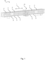
- Fig. 1 schematically illustrates a part of a printer 100 according to an embodiment of the present invention.
- Parts of the printer 100 which are well known but not essential for the description of the present invention are omitted for the sake of clarity.
- no housing, medium transport system, print head and so on are shown although they will typically be present in the printer 100.
- the printer comprises, among other parts, two guidance rails 10 arranged in parallel to one another, each extending along a (the same) longitudinal direction L but at a perpendicular distance from one another.
- mounting sites 12 are provided which will be described in more detail in the following.
- a print head carriage 150 is moveably mounted between the guidance rails 10 such as to be moveable by an actuator (not shown) bidirectionally in the longitudinal direction L.
- the print head carriage 150 would carry a print head configured to eject the marking agent (e.g. ink) in the downward direction.
- the distances between the mounting sites 12 are not shown to scale in Fig. 1 .
- Fig. 2 shows further details of the assembly shown in Fig. 1 , with the print head carriage 150 now left out.
- the mounting sites 12 are provided as holes or bores in the guidance rail 10.
- the holes or bores may be punched out of a blank metal strip to produce a metal guidance rail 10, or they may be bored out of a blank metal strip.
- the guidance rail 10 could also be made from plastic in which case the mounting sites 12 may be cut into a blank plastic strip to produce a plastic guidance rail 10, or the guidance rail 10 may be produced by injections molding as already comprising the holes, or the guidance rail 10 may be produced by additive manufacturing (e.g. "3D printing") from a material comprising (or consisting of) metal, plastic and/or ceramics as already comprising the holes.
- Fig. 2 also shows that the guidance rail 10 may be mounted to a framework 110 of the printer 100 (or any other part of the printer 100) using mounting elements 13. These mounting elements 13 may be any type of mounting means, for example, screws or bolts.
- a runner block 14 is moveably mounted to the guidance rail 10 such as to be able to move along the longitudinal direction L.
- the print head carriage 150 may be mounted on at least one runner block 14 on each guidance rail 10.
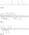
- FIG. 3 schematically illustrates a guidance rail 1 according to the prior art (e.g. according to EP 3 564 038 A1 ), wherein mounting sites 4 are arranged at equidistant intervals.
- a schematic graph 5 indicates in an exaggerated manner how much play the different portions of the guidance rail 1 have due to the positioning of the mounting sites 4: the play is minimal at each mounting site 4, increases up towards a maximum precisely halfway between that mounting site 4 and the next, and then decreases again to the minimum.
- the regularity of this graph 5 indicates the susceptibility of the guidance rail 1 of the prior art to vibrations, as the graph 5 can also be interpreted to show the fundamental vibration mode between adjacent mounting sites 4.
- Fig. 4 schematically illustrates a guidance rail 10 according to an embodiment of the present invention.
- equidistant center positions 16-1, 16-2, 16-3, ... (in short: 16-i) are defined for the mounting sites 12-1, 12-2, ... (in short: 12-i).
- the center positions 16-i are marked by diamond symbols and the mounting sites 12-1 by circles.
- Each center position 16-i is at the center of a periodically repeating cell 15. Both the center positions 16-i and the cell 15 are not necessarily marked on the guidance rail in any way but are defined and described in order to understand the embodiment better.
- Each mounting site 12-i is arranged within a predefined tolerance interval around a (or: its) respective one of the center positions 16-i.
- the tolerance interval in this respect is preferably only considered along the longitudinal direction L.
- the tolerance interval is preferably arranged symmetrically around its respective center position 16-i, or, in other words, each center position 16-i is arranged at the center (in the longitudinal direction L) of its respective tolerance interval.
- each mounting site 12-i to the (or: its) respective center position 16-i is different for at least two of the mounting sites 12-i.
- Fig. 4 shows a distance d12 between a first mounting site 12-1 and a second mounting site 12-2 being smaller than a distance d23 between the second mounting site 12-2 and a third mounting site 12-3.
- the total width of the tolerance interval is smaller than the (constant and equal throughout the guidance rail 10) distance between two adjacent center positions 16-i, 16-(i+1), more preferably smaller than 75% of that distance, most preferably smaller than 50% of that distance.
- this provides a suitable balance between the advantages of different distances d12, d23, ... between the mounting sites 12-1, 12-2, ...(in order to reduce vibration) and the advantages of equidistant distances (in order to provide stability of the mounting of the guidance rail 10 to the printer 100).
- each mounting site 12-i (and only one) is randomly arranged within the predefined tolerance interval around its respective center position 16-i.
- a graph 5 has been included as well which, as in Fig. 3 , indicates (in an exaggerated manner) the play that the guidance rail 10 has in the perpendicular direction P and, consequently, also the fundamental mode of vibration. Because of the different distances d12, d23, ... it is evident that also these fundamental modes of graph 5 in Fig. 4 are (preferably) all different and that therefore no vibrational mode of the guidance rail 10 as a whole can be induced.
- Fig. 5 schematically illustrates a guidance rail 20 according to another embodiment of the present invention.
- two different distance values are defined for adjacent mounting sites 12-i, and the two different distance values A and B alternate regularly along the row of mounting sites 12-i.
- the ratio of adjacently applied distance values is between 1:1 and 1:5, preferably between 1:2 and 1:4, more preferably between 1:3 and 1:4.
- One basic idea of the invention may be summarized as follows: distances between mounting sites of a guidance rail for a print head carriage are provided non-equidistantly in order to reduce vibration modes and therefore reduce the chances and intensity of vibrations induced the in the guidance rail by the dynamic movement of the print head carriage.
Landscapes
- Character Spaces And Line Spaces In Printers (AREA)
Abstract
Description
- The present invention generally pertains to a guidance rail for a print head carriage with reduced susceptibility to vibrations as well as to a printer comprising such a guidance rail.
- In many types of printers, a print head carriage is moved relative to a medium such as a sheet or a roll of paper or foil of plastic or the like. Such printers are also sometimes designated as "scanning printing systems". The "scanning printing systems" comprise a carriage configured to, in printing operation, move in reciprocation in a main scanning direction over the medium. The print head carriage carries a print head, which marks the medium with a marking agent such as ink or a conductive paste in order to create text, patterns, colors, images, electrical circuits and/or the like on the medium.
- The print head carriage typically moves bidirectionally along a linear path and is typically mounted between two so-called runner blocks, which in turn are moveably arranged on a respective one of two guidance rails installed in parallel in the printer. The mounting of such a guidance rail in a carriage printing system is usually designed to be equidistant, for example with a mounting pitch of 60 millimeters.
-
EP 3 564 038 A1 discloses a guiding structure for a print head carriage in which equidistant mounting sites are provided for an array of mounting bodies for mounting the guiding structure to the rest of the printer. -
US 2018 /079 240 A1 describes an assembly for moving a carriage of a printer. Regarding a vibration problem that may arise when the carriage moves, it is suggested to include a flexible support element and a tensioner assembly for tensioning the flexible support element. By controlling the tension of the flexible support element, it is endeavored to dampen vibrations of the assembly caused by the movement of the carriage. - It has been found by the inventors that the typical equidistant arrangement of the mounting sites of the guidance rail may lead to an undesired increase in vibration in and of the guidance rail due to the movement of the print head carriage. In particular, when the print head carriage is moving with a constant speed along the guidance rail for an extended period of time, this induces vibrations in the guidance rail. Since the guidance rail is fixated at each of the mounting sites which are equidistant in the prior art, this creates a regular pattern of fixed points. Between these fixed points at the mounting sites, the guidance rail is comparatively freer to shift. Consequently, such a guidance rail installed in a printer is susceptible to particular vibration frequencies induced by the print head carriage, in particular to frequencies that are integer multiplies of the base distance between the mounting sites. Vibrations in the guidance rail, in turn, negatively affect the longevity and the precision of the print head carriage.
- It is therefore an objective of the present invention to provide a guidance rail, and a printer with a guidance rail, which are less susceptible to these types of vibrations.
- These objectives are fulfilled by the subject matter of the independent claims.
- Accordingly, the invention provides a guidance rail for a print head carriage, the guidance rail having mounting sites arranged essentially in a row. The mounting sites are configured for applying mounting elements for mounting the guidance rail to a printer. At least two distances between any adjacent mounting sites are non-equal.
- In other words, the mounting sites of the guidance rail are non-equidistant overall as there is at least one distance between one pair of adjacent mounting sites which is different from at least one other distance between one other pair of adjacent mounting sites (wherein the one pair and the other pair may have at most one mounting site in common).
- Advantageously, by arranging the mounting sites non-equidistant, the strict regularity of the arrangement of mounting sites is removed and the susceptibility of the guidance rail to vibrations is reduced. It is preferred that there is a plurality of first distances between adjacent mounting sites which are different from a plurality of second distances between adjacent mounting sites. In general, the less regular the arrangement of mounting sites on the guidance rail is, the less susceptible the guidance rail is to vibrations.
- The mounting site being arranged essentially in a row may be understood to mean that they are arranged in a strict row as much as usual tolerances allow or that they are arranged in a row with perpendicular deviations of each mounting site from an ideal, strict row between (including) zero and a maximum deviation value, MDV. The MDV may as low as zero and as large as, for example, the size of the mounting site in the direction perpendicular to the ideal, strict row. This direction may also be simply designated as the "perpendicular direction", i.e., perpendicular to the longitudinal direction along which the guidance rail itself extends. Thus, the maximum distance between any two mounting sites in the perpendicular direction may be two times MDV, in case that one of the mounting site is maximally deviated in the positive perpendicular direction and another one of the mounting sites is maximally deviated in the negative perpendicular direction.
- In some advantageous embodiments, refinements, or variants of embodiments, equidistant center positions for the mounting sites are defined, each mounting site is arranged within a predefined tolerance interval around a respective one of the center positions, and the relative position of each mounting site to the respective center position is different for at least two of the mounting sites. In each tolerance interval, there is only a single center position and only a single mounting site.
- The equidistant center positions have the effect that the guidance rail is, on average, fastened to the printer at regular (equidistant) intervals such that at no point of the guidance rail there is an excess of play. On the other hand, since the mounting sites are not arranged exactly at the center positions but at (at least partially, i.e., at least for some mounting sites) different relative positions thereto, the strict regularity of the mounting sites is advantageously broken, and the guidance rail is less susceptible to vibrations.
- Taking this idea further, more preferably each mounting site is randomly arranged within the predefined tolerance interval around its respective center position. This strongly reduces the chances that the guidance rail has any resonance frequency that can be excited by the movement of the carriage. The term "randomly" shall here be understood to include both true randomness as well as pseudo-randomness in the mathematical sense.
- In some advantageous embodiments, refinements, or variants of embodiments, each distance between any two adjacent mounting sites is different. This is another way to strongly reduce the chances that the guidance rail has any resonance frequency that can be excited by the movement of the print head carriage.
- In some advantageous embodiments, refinements, or variants of embodiments, at least two different distance values are defined for adjacent mounting sites, and wherein the at least two different distance values alternate regularly along the row of mounting sites. It should be noted that whenever herein distances between mounting sites are discussed, this pertains to distances between adjacent mounting sites unless explicitly specified otherwise. Two different distances values A, B mean that the distances between pairs of adjacent mounting sites along the longitudinal direction vary as A-B-A-B-A... and so on. For three different distances values A, B, and C, the order may be A-B-C-A-B-C-A ... and so on. The largest resonance frequency would be the largest common divisor of A, B, C, ... and so on which will in general be the smaller, the more different distance values, A, B, C, D, ... and so on are present.
- Advantageously, the ratio of adjacently applied distance values (i.e. the ratio of A:B, of B:C, .. and so on) is between 1:1 and 1:5, preferably between 1:2 and 1:4, more preferably between 1:3 and 1:4. These values empirically provide a good balance between the advantages of fixing the guidance rail at equidistant mounting sites for reasons of stability and the advantages of reducing its susceptibility to vibrations.
- In some advantageous embodiments, refinements, or variants of embodiments, the mounting sites are configured as holes or bores through which mounting elements for mounting the guidance rail to the printer can be inserted. The mounting elements may in particular be mounting means such as screws, bolts, and/or the like. The extent of the hole or bore in the perpendicular direction, as a percentage of the extent of the guidance rail itself along the perpendicular direction, is preferably larger than 50%, more preferably larger than 70%.
- The invention further provides a printer comprising at least one guidance rail according to an embodiment of the present invention, the at least one guidance rail being mounted to the printer by mounting elements attached at the mounting sites of the guidance rail. Preferably, at least (or exactly) two guidance rails are provided and mounted to the printer, more preferably in parallel for providing additional stability to the moving print head carriage.
- In some advantageous embodiments, refinements, or variants of embodiments, the printer comprises a print head cartridge, wherein two guidance rails according to any embodiment of the present invention are arranged in parallel. At least one runner block is movably mounted on each guidance rail, and the print head carriage is mounted on the at least two runner blocks.
- It is further preferred that the first, second, third, ... and so on mounting sites of the first guidance rail are positioned at different positions along the longitudinal direction than the respective first, second, third, ... and so on mounting sites of the second guidance rail. This will further reduce the susceptibility of the assembly of the guidance rails and the print head carriage to vibrations. In other words, starting from a mounting site of a first guidance rail and moving towards another guidance rail along the perpendicular direction, it is preferred if no other mounting site is encountered at the same position with respect to the longitudinal direction.
- The present invention will become more fully understood from the detailed description given hereinbelow and the accompanying schematic drawings which are given by way of illustration only, and thus are not limitative of the present invention, and wherein:
- Fig. 1
- schematically illustrates a part of a printer according to an embodiment of the present invention, which comprises two guidance rails according to further embodiments of the present invention;
- Fig. 2
- schematically illustrates a guidance rail of
Fig. 1 in more detail; - Fig. 3
- schematically illustrates a guidance rail according to the prior art;
- Fig. 4
- schematically illustrates a guidance rail according to an embodiment of the present invention; and
- Fig. 5
- schematically illustrates a guidance rail according to another embodiment of the present invention.
- The present invention will now be described with reference to the accompanying drawings, wherein the same reference numerals have been used to identify the same or similar elements throughout the several views, and in some instances throughout the several embodiments.
-
Fig. 1 schematically illustrates a part of aprinter 100 according to an embodiment of the present invention. Parts of theprinter 100 which are well known but not essential for the description of the present invention are omitted for the sake of clarity. For example, no housing, medium transport system, print head and so on are shown although they will typically be present in theprinter 100. - What is shown in
Fig. 1 is that the printer comprises, among other parts, twoguidance rails 10 arranged in parallel to one another, each extending along a (the same) longitudinal direction L but at a perpendicular distance from one another. Along eachguidance rail 10, mountingsites 12 are provided which will be described in more detail in the following. Aprint head carriage 150 is moveably mounted between the guidance rails 10 such as to be moveable by an actuator (not shown) bidirectionally in the longitudinal direction L. In the shown depiction, theprint head carriage 150 would carry a print head configured to eject the marking agent (e.g. ink) in the downward direction. The distances between the mountingsites 12 are not shown to scale inFig. 1 . -
Fig. 2 shows further details of the assembly shown inFig. 1 , with theprint head carriage 150 now left out. In this embodiment, the mountingsites 12 are provided as holes or bores in theguidance rail 10. The holes or bores may be punched out of a blank metal strip to produce ametal guidance rail 10, or they may be bored out of a blank metal strip. Theguidance rail 10 could also be made from plastic in which case the mountingsites 12 may be cut into a blank plastic strip to produce aplastic guidance rail 10, or theguidance rail 10 may be produced by injections molding as already comprising the holes, or theguidance rail 10 may be produced by additive manufacturing (e.g. "3D printing") from a material comprising (or consisting of) metal, plastic and/or ceramics as already comprising the holes. -
Fig. 2 also shows that theguidance rail 10 may be mounted to aframework 110 of the printer 100 (or any other part of the printer 100) using mountingelements 13. These mountingelements 13 may be any type of mounting means, for example, screws or bolts. Arunner block 14 is moveably mounted to theguidance rail 10 such as to be able to move along the longitudinal direction L. Theprint head carriage 150 may be mounted on at least onerunner block 14 on eachguidance rail 10. -
Fig. 3 schematically illustrates aguidance rail 1 according to the prior art (e.g. according toEP 3 564 038 A1 ), wherein mountingsites 4 are arranged at equidistant intervals. Aschematic graph 5 indicates in an exaggerated manner how much play the different portions of theguidance rail 1 have due to the positioning of the mounting sites 4: the play is minimal at each mountingsite 4, increases up towards a maximum precisely halfway between that mountingsite 4 and the next, and then decreases again to the minimum. The regularity of thisgraph 5 indicates the susceptibility of theguidance rail 1 of the prior art to vibrations, as thegraph 5 can also be interpreted to show the fundamental vibration mode between adjacent mountingsites 4. -
Fig. 4 schematically illustrates aguidance rail 10 according to an embodiment of the present invention. Along theguidance rail 10, equidistant center positions 16-1, 16-2, 16-3, ... (in short: 16-i) are defined for the mounting sites 12-1, 12-2, ... (in short: 12-i). The center positions 16-i are marked by diamond symbols and the mounting sites 12-1 by circles. Each center position 16-i is at the center of a periodically repeatingcell 15. Both the center positions 16-i and thecell 15 are not necessarily marked on the guidance rail in any way but are defined and described in order to understand the embodiment better. - Each mounting site 12-i is arranged within a predefined tolerance interval around a (or: its) respective one of the center positions 16-i. The tolerance interval in this respect is preferably only considered along the longitudinal direction L. The tolerance interval is preferably arranged symmetrically around its respective center position 16-i, or, in other words, each center position 16-i is arranged at the center (in the longitudinal direction L) of its respective tolerance interval.
- The relative position of each mounting site 12-i to the (or: its) respective center position 16-i is different for at least two of the mounting sites 12-i. As an example,
Fig. 4 shows a distance d12 between a first mounting site 12-1 and a second mounting site 12-2 being smaller than a distance d23 between the second mounting site 12-2 and a third mounting site 12-3. - The tolerance interval may extend up to half the distance between the center position 16-i and the respective next center position 16-j, with j=i+1 or j=1-i. Preferably, the total width of the tolerance interval is smaller than the (constant and equal throughout the guidance rail 10) distance between two adjacent center positions 16-i, 16-(i+1), more preferably smaller than 75% of that distance, most preferably smaller than 50% of that distance. Again, this provides a suitable balance between the advantages of different distances d12, d23, ... between the mounting sites 12-1, 12-2, ...(in order to reduce vibration) and the advantages of equidistant distances (in order to provide stability of the mounting of the
guidance rail 10 to the printer 100). Preferably, each mounting site 12-i (and only one) is randomly arranged within the predefined tolerance interval around its respective center position 16-i. - In
Fig. 4 agraph 5 has been included as well which, as inFig. 3 , indicates (in an exaggerated manner) the play that theguidance rail 10 has in the perpendicular direction P and, consequently, also the fundamental mode of vibration. Because of the different distances d12, d23, ... it is evident that also these fundamental modes ofgraph 5 inFig. 4 are (preferably) all different and that therefore no vibrational mode of theguidance rail 10 as a whole can be induced. -
Fig. 5 schematically illustrates aguidance rail 20 according to another embodiment of the present invention. - In the
guidance rail 20 ofFig. 5 , two different distance values (e.g. designated as A and B) are defined for adjacent mounting sites 12-i, and the two different distance values A and B alternate regularly along the row of mounting sites 12-i. This means that d12=A, d23=B, d34=A, ... and so on. The ratio of adjacently applied distance values (here: the ratio of A:B) is between 1:1 and 1:5, preferably between 1:2 and 1:4, more preferably between 1:3 and 1:4. Although theguidance rail 20 of the embodiment ofFig. 5 (or any other embodiment with a larger number of regularly alternating distance values A, B, C, ...) will in general be more susceptible to vibrations than the still less regular embodiment ofFig. 4 , it has the advantage that its manufacture may be easier, as also in the manufacturing, the present regularities can be exploited to reduce the manufacturing effort. - While detailed embodiments of the present invention are disclosed herein, it is to be understood that the disclosed embodiments are merely exemplary of the invention, which can be embodied in various forms. Therefore, specific structural and functional details disclosed herein are not to be interpreted as limiting, but merely as a basis for the claims and as a representative basis for teaching one skilled in the art to variously employ the present invention in virtually any appropriately detailed structure. In particular, features presented and described in separate dependent claims may be applied in combination and any advantageous combination of such claims are herewith disclosed.
- It will be evident that the described embodiments may be varied in many ways. All such modifications as would be evident to one skilled in the art starting from what is explicitly described are intended to be included.
- One basic idea of the invention may be summarized as follows: distances between mounting sites of a guidance rail for a print head carriage are provided non-equidistantly in order to reduce vibration modes and therefore reduce the chances and intensity of vibrations induced the in the guidance rail by the dynamic movement of the print head carriage.
-
- 1
- guidance rail of the prior art
- 4
- mounting site of the prior art
- 5
- graph showing play of guidance rail
- 10
- guidance rail
- 12
- mounting site
- 12-i
- mounting site
- 13
- mounting element
- 14
- runner block
- 15
- cell
- 16-i
- center position
- 20
- guidance rail
- 100
- printer
- 110
- framework
- 150
- print head carriage
- L
- longitudinal direction
- P
- perpendicular direction
Claims (9)
- A guidance rail (10; 20) for a print head carriage (150), having mounting sites (12-i) arranged essentially in a row and configured for applying mounting elements (13) for mounting the guidance rail (10; 20) to a printer (100),
characterized in that
at least two distances (d12, d23, d34) between any adjacent mounting sites (12-i, 12-(i+1)) are non-equal. - The guidance rail (10; 20) of claim 1,
wherein equidistant center positions (16-i) for the mounting sites (12-i) are defined, each mounting site (12-i) is arranged within a predefined tolerance interval around a respective one of the center positions (16-i), and the relative position of each mounting site (12-i) to the respective center position (16-i) is different for at least two of the mounting sites (12-i). - The guidance rail (10; 20) of claim 2,
wherein each mounting site (12-i) is randomly arranged within the predefined tolerance interval around its respective center position (16-i). - The guidance rail (10; 20) of any of claims 1 to 3,
wherein each distance (d12, d23) between any two adjacent mounting sites (12-1, 12-2) is different. - The guidance rail (10; 20) of claim 1,
wherein at least two different distance values (A, B) are defined for adjacent mounting sites (12-i), and wherein the at least two different distance values (A, B) alternate regularly along the row of mounting sites (12-i). - The guidance rail (10; 20) of claim 5,
wherein the ratio of adjacently applied distance values (A, B) is between 1:1 and 1:5, preferably between 1:2 and 1:4, more preferably between 1:3 and 1:4. - The guidance rail (10; 20) of any of claims 1 to 5,
wherein the mounting sites (12-i) are configured as holes or bores through which mounting elements (13) for mounting the guidance rail (10; 20) to the printer (100) can be inserted. - A printer (100) comprising at least one guidance rail (10; 20) according to any of claims 1 to 7, the at least one guidance rail (10; 20) being mounted to the printer (100) by mounting elements (13) attached at the mounting sites (12-i) of the guidance rail (10; 20).
- The printer (100) of claim 8, comprising a print head cartridge (150), wherein two guidance rails (10; 20) according to any of claims 1 to 7 are arranged in parallel, at least one runner block (16) is movably mounted on each guidance rail (10; 20), and the print head carriage(150) is mounted on the at least two runner blocks (16).
Priority Applications (1)
| Application Number | Priority Date | Filing Date | Title |
|---|---|---|---|
| EP21216158.2A EP4197801B1 (en) | 2021-12-20 | 2021-12-20 | Printer and guidance rail for a print head carriage |
Applications Claiming Priority (1)
| Application Number | Priority Date | Filing Date | Title |
|---|---|---|---|
| EP21216158.2A EP4197801B1 (en) | 2021-12-20 | 2021-12-20 | Printer and guidance rail for a print head carriage |
Publications (2)
| Publication Number | Publication Date |
|---|---|
| EP4197801A1 true EP4197801A1 (en) | 2023-06-21 |
| EP4197801B1 EP4197801B1 (en) | 2024-12-04 |
Family
ID=78957819
Family Applications (1)
| Application Number | Title | Priority Date | Filing Date |
|---|---|---|---|
| EP21216158.2A Active EP4197801B1 (en) | 2021-12-20 | 2021-12-20 | Printer and guidance rail for a print head carriage |
Country Status (1)
| Country | Link |
|---|---|
| EP (1) | EP4197801B1 (en) |
Citations (6)
| Publication number | Priority date | Publication date | Assignee | Title |
|---|---|---|---|---|
| US20110181659A1 (en) * | 2010-01-26 | 2011-07-28 | Canon Kabushiki Kaisha | Recording apparatus |
| US20110249054A1 (en) * | 2010-04-12 | 2011-10-13 | Kinpo Electronics Inc. | Fixing structure for print head carriage rod and fixing method thereof |
| US20170106686A1 (en) * | 2015-10-20 | 2017-04-20 | Seiko Epson Corporation | Liquid Discharging Apparatus and Method of Adjusting Rail Section in Liquid Discharging Apparatus |
| US20180079240A1 (en) | 2016-09-22 | 2018-03-22 | Océ Holding B.V. | Assembly for moving a carriage |
| EP3564038A1 (en) | 2018-05-04 | 2019-11-06 | OCE Holding B.V. | Guiding structure for a print head carriage |
| US20200047527A1 (en) * | 2018-08-10 | 2020-02-13 | OCE Holding B.V. | Assembly of a guiding structure and a print head carriage |
-
2021
- 2021-12-20 EP EP21216158.2A patent/EP4197801B1/en active Active
Patent Citations (6)
| Publication number | Priority date | Publication date | Assignee | Title |
|---|---|---|---|---|
| US20110181659A1 (en) * | 2010-01-26 | 2011-07-28 | Canon Kabushiki Kaisha | Recording apparatus |
| US20110249054A1 (en) * | 2010-04-12 | 2011-10-13 | Kinpo Electronics Inc. | Fixing structure for print head carriage rod and fixing method thereof |
| US20170106686A1 (en) * | 2015-10-20 | 2017-04-20 | Seiko Epson Corporation | Liquid Discharging Apparatus and Method of Adjusting Rail Section in Liquid Discharging Apparatus |
| US20180079240A1 (en) | 2016-09-22 | 2018-03-22 | Océ Holding B.V. | Assembly for moving a carriage |
| EP3564038A1 (en) | 2018-05-04 | 2019-11-06 | OCE Holding B.V. | Guiding structure for a print head carriage |
| US20200047527A1 (en) * | 2018-08-10 | 2020-02-13 | OCE Holding B.V. | Assembly of a guiding structure and a print head carriage |
Also Published As
| Publication number | Publication date |
|---|---|
| EP4197801B1 (en) | 2024-12-04 |
Similar Documents
| Publication | Publication Date | Title |
|---|---|---|
| US4044668A (en) | Print hammer mechanism | |
| US20100053252A1 (en) | Liquid discharging apparatus and method of controlling liquid discharging apparatus | |
| EP3069878B1 (en) | Printing device and printing method | |
| EP1364790B1 (en) | Ink-jet printing head having a plurality of actuator units and a plurality of manifold chambers | |
| ATE322987T1 (en) | GUIDE ARRANGEMENT FOR INK JET PRINTER | |
| EP4197801B1 (en) | Printer and guidance rail for a print head carriage | |
| US20040150693A1 (en) | Droplet ejecting head and droplet ejecting apparatus | |
| EP3293003A1 (en) | Ink jet head drive device and ink jet head | |
| EP0425285B1 (en) | Dot type printing head for use in a serial printer | |
| US8764142B2 (en) | Liquid ejection apparatus and control method thereof | |
| US6350011B1 (en) | Print head arrangement | |
| KR102084934B1 (en) | Line head and inkjet apparatus | |
| JP2881616B2 (en) | Ink jet head device | |
| WO2001064451A1 (en) | Carriage drive system for a serial printer which minimizes registration errors | |
| US20030227511A1 (en) | Scan axis assembly for a printer | |
| US8562105B2 (en) | Fixing structure for print head carriage rod and fixing method thereof | |
| CN103381705A (en) | Liquid ejecting head unit and liquid ejecting apparatus | |
| CN222645655U (en) | Spliced printing head and ink-jet printer | |
| JP4402658B2 (en) | Inkjet recording device | |
| JP5074842B2 (en) | Wire dot print head and printer | |
| JP4560673B2 (en) | Ink jet head and droplet discharge device using the same | |
| KR20160026708A (en) | Liquid discharge apparatus and liquid discharge head | |
| JP5615574B2 (en) | Recording apparatus and recording method | |
| JPH02286246A (en) | inkjet head | |
| JP2005186599A (en) | Image recording apparatus |
Legal Events
| Date | Code | Title | Description |
|---|---|---|---|
| PUAI | Public reference made under article 153(3) epc to a published international application that has entered the european phase |
Free format text: ORIGINAL CODE: 0009012 |
|
| STAA | Information on the status of an ep patent application or granted ep patent |
Free format text: STATUS: THE APPLICATION HAS BEEN PUBLISHED |
|
| AK | Designated contracting states |
Kind code of ref document: A1 Designated state(s): AL AT BE BG CH CY CZ DE DK EE ES FI FR GB GR HR HU IE IS IT LI LT LU LV MC MK MT NL NO PL PT RO RS SE SI SK SM TR |
|
| STAA | Information on the status of an ep patent application or granted ep patent |
Free format text: STATUS: REQUEST FOR EXAMINATION WAS MADE |
|
| 17P | Request for examination filed |
Effective date: 20231221 |
|
| RBV | Designated contracting states (corrected) |
Designated state(s): AL AT BE BG CH CY CZ DE DK EE ES FI FR GB GR HR HU IE IS IT LI LT LU LV MC MK MT NL NO PL PT RO RS SE SI SK SM TR |
|
| GRAP | Despatch of communication of intention to grant a patent |
Free format text: ORIGINAL CODE: EPIDOSNIGR1 |
|
| STAA | Information on the status of an ep patent application or granted ep patent |
Free format text: STATUS: GRANT OF PATENT IS INTENDED |
|
| INTG | Intention to grant announced |
Effective date: 20240710 |
|
| GRAS | Grant fee paid |
Free format text: ORIGINAL CODE: EPIDOSNIGR3 |
|
| GRAA | (expected) grant |
Free format text: ORIGINAL CODE: 0009210 |
|
| STAA | Information on the status of an ep patent application or granted ep patent |
Free format text: STATUS: THE PATENT HAS BEEN GRANTED |
|
| AK | Designated contracting states |
Kind code of ref document: B1 Designated state(s): AL AT BE BG CH CY CZ DE DK EE ES FI FR GB GR HR HU IE IS IT LI LT LU LV MC MK MT NL NO PL PT RO RS SE SI SK SM TR |
|
| REG | Reference to a national code |
Ref country code: CH Ref legal event code: EP |
|
| REG | Reference to a national code |
Ref country code: DE Ref legal event code: R096 Ref document number: 602021022796 Country of ref document: DE |
|
| REG | Reference to a national code |
Ref country code: IE Ref legal event code: FG4D |
|
| REG | Reference to a national code |
Ref country code: NL Ref legal event code: FP |
|
| REG | Reference to a national code |
Ref country code: LT Ref legal event code: MG9D |
|
| PG25 | Lapsed in a contracting state [announced via postgrant information from national office to epo] |
Ref country code: HR Free format text: LAPSE BECAUSE OF FAILURE TO SUBMIT A TRANSLATION OF THE DESCRIPTION OR TO PAY THE FEE WITHIN THE PRESCRIBED TIME-LIMIT Effective date: 20241204 |
|
| PG25 | Lapsed in a contracting state [announced via postgrant information from national office to epo] |
Ref country code: FI Free format text: LAPSE BECAUSE OF FAILURE TO SUBMIT A TRANSLATION OF THE DESCRIPTION OR TO PAY THE FEE WITHIN THE PRESCRIBED TIME-LIMIT Effective date: 20241204 |
|
| PG25 | Lapsed in a contracting state [announced via postgrant information from national office to epo] |
Ref country code: BG Free format text: LAPSE BECAUSE OF FAILURE TO SUBMIT A TRANSLATION OF THE DESCRIPTION OR TO PAY THE FEE WITHIN THE PRESCRIBED TIME-LIMIT Effective date: 20241204 |
|
| PG25 | Lapsed in a contracting state [announced via postgrant information from national office to epo] |
Ref country code: ES Free format text: LAPSE BECAUSE OF FAILURE TO SUBMIT A TRANSLATION OF THE DESCRIPTION OR TO PAY THE FEE WITHIN THE PRESCRIBED TIME-LIMIT Effective date: 20241204 |
|
| PG25 | Lapsed in a contracting state [announced via postgrant information from national office to epo] |
Ref country code: NO Free format text: LAPSE BECAUSE OF FAILURE TO SUBMIT A TRANSLATION OF THE DESCRIPTION OR TO PAY THE FEE WITHIN THE PRESCRIBED TIME-LIMIT Effective date: 20250304 |
|
| PG25 | Lapsed in a contracting state [announced via postgrant information from national office to epo] |
Ref country code: LV Free format text: LAPSE BECAUSE OF FAILURE TO SUBMIT A TRANSLATION OF THE DESCRIPTION OR TO PAY THE FEE WITHIN THE PRESCRIBED TIME-LIMIT Effective date: 20241204 Ref country code: GR Free format text: LAPSE BECAUSE OF FAILURE TO SUBMIT A TRANSLATION OF THE DESCRIPTION OR TO PAY THE FEE WITHIN THE PRESCRIBED TIME-LIMIT Effective date: 20250305 |
|
| PG25 | Lapsed in a contracting state [announced via postgrant information from national office to epo] |
Ref country code: RS Free format text: LAPSE BECAUSE OF FAILURE TO SUBMIT A TRANSLATION OF THE DESCRIPTION OR TO PAY THE FEE WITHIN THE PRESCRIBED TIME-LIMIT Effective date: 20250304 |
|
| REG | Reference to a national code |
Ref country code: AT Ref legal event code: MK05 Ref document number: 1747777 Country of ref document: AT Kind code of ref document: T Effective date: 20241204 |
|
| PG25 | Lapsed in a contracting state [announced via postgrant information from national office to epo] |
Ref country code: SM Free format text: LAPSE BECAUSE OF FAILURE TO SUBMIT A TRANSLATION OF THE DESCRIPTION OR TO PAY THE FEE WITHIN THE PRESCRIBED TIME-LIMIT Effective date: 20241204 |
|
| PG25 | Lapsed in a contracting state [announced via postgrant information from national office to epo] |
Ref country code: PL Free format text: LAPSE BECAUSE OF FAILURE TO SUBMIT A TRANSLATION OF THE DESCRIPTION OR TO PAY THE FEE WITHIN THE PRESCRIBED TIME-LIMIT Effective date: 20241204 |
|
| PG25 | Lapsed in a contracting state [announced via postgrant information from national office to epo] |
Ref country code: IS Free format text: LAPSE BECAUSE OF FAILURE TO SUBMIT A TRANSLATION OF THE DESCRIPTION OR TO PAY THE FEE WITHIN THE PRESCRIBED TIME-LIMIT Effective date: 20250404 |
|
| PG25 | Lapsed in a contracting state [announced via postgrant information from national office to epo] |
Ref country code: PT Free format text: LAPSE BECAUSE OF FAILURE TO SUBMIT A TRANSLATION OF THE DESCRIPTION OR TO PAY THE FEE WITHIN THE PRESCRIBED TIME-LIMIT Effective date: 20250404 |
|
| PG25 | Lapsed in a contracting state [announced via postgrant information from national office to epo] |
Ref country code: EE Free format text: LAPSE BECAUSE OF FAILURE TO SUBMIT A TRANSLATION OF THE DESCRIPTION OR TO PAY THE FEE WITHIN THE PRESCRIBED TIME-LIMIT Effective date: 20241204 |
|
| PG25 | Lapsed in a contracting state [announced via postgrant information from national office to epo] |
Ref country code: RO Free format text: LAPSE BECAUSE OF FAILURE TO SUBMIT A TRANSLATION OF THE DESCRIPTION OR TO PAY THE FEE WITHIN THE PRESCRIBED TIME-LIMIT Effective date: 20241204 Ref country code: AT Free format text: LAPSE BECAUSE OF FAILURE TO SUBMIT A TRANSLATION OF THE DESCRIPTION OR TO PAY THE FEE WITHIN THE PRESCRIBED TIME-LIMIT Effective date: 20241204 |
|
| PG25 | Lapsed in a contracting state [announced via postgrant information from national office to epo] |
Ref country code: SK Free format text: LAPSE BECAUSE OF FAILURE TO SUBMIT A TRANSLATION OF THE DESCRIPTION OR TO PAY THE FEE WITHIN THE PRESCRIBED TIME-LIMIT Effective date: 20241204 |
|
| PG25 | Lapsed in a contracting state [announced via postgrant information from national office to epo] |
Ref country code: CZ Free format text: LAPSE BECAUSE OF FAILURE TO SUBMIT A TRANSLATION OF THE DESCRIPTION OR TO PAY THE FEE WITHIN THE PRESCRIBED TIME-LIMIT Effective date: 20241204 |
|
| PG25 | Lapsed in a contracting state [announced via postgrant information from national office to epo] |
Ref country code: IT Free format text: LAPSE BECAUSE OF FAILURE TO SUBMIT A TRANSLATION OF THE DESCRIPTION OR TO PAY THE FEE WITHIN THE PRESCRIBED TIME-LIMIT Effective date: 20241204 |
|
| REG | Reference to a national code |
Ref country code: CH Ref legal event code: PL |
|
| PG25 | Lapsed in a contracting state [announced via postgrant information from national office to epo] |
Ref country code: LU Free format text: LAPSE BECAUSE OF NON-PAYMENT OF DUE FEES Effective date: 20241220 |
|
| REG | Reference to a national code |
Ref country code: DE Ref legal event code: R097 Ref document number: 602021022796 Country of ref document: DE |
|
| PG25 | Lapsed in a contracting state [announced via postgrant information from national office to epo] |
Ref country code: SE Free format text: LAPSE BECAUSE OF FAILURE TO SUBMIT A TRANSLATION OF THE DESCRIPTION OR TO PAY THE FEE WITHIN THE PRESCRIBED TIME-LIMIT Effective date: 20241204 |
|
| PG25 | Lapsed in a contracting state [announced via postgrant information from national office to epo] |
Ref country code: MC Free format text: LAPSE BECAUSE OF FAILURE TO SUBMIT A TRANSLATION OF THE DESCRIPTION OR TO PAY THE FEE WITHIN THE PRESCRIBED TIME-LIMIT Effective date: 20241204 |
|
| REG | Reference to a national code |
Ref country code: BE Ref legal event code: MM Effective date: 20241231 |
|
| PG25 | Lapsed in a contracting state [announced via postgrant information from national office to epo] |
Ref country code: DK Free format text: LAPSE BECAUSE OF FAILURE TO SUBMIT A TRANSLATION OF THE DESCRIPTION OR TO PAY THE FEE WITHIN THE PRESCRIBED TIME-LIMIT Effective date: 20241204 |
|
| PLBE | No opposition filed within time limit |
Free format text: ORIGINAL CODE: 0009261 |
|
| STAA | Information on the status of an ep patent application or granted ep patent |
Free format text: STATUS: NO OPPOSITION FILED WITHIN TIME LIMIT |
|
| PG25 | Lapsed in a contracting state [announced via postgrant information from national office to epo] |
Ref country code: BE Free format text: LAPSE BECAUSE OF NON-PAYMENT OF DUE FEES Effective date: 20241231 |
|
| PG25 | Lapsed in a contracting state [announced via postgrant information from national office to epo] |
Ref country code: CH Free format text: LAPSE BECAUSE OF NON-PAYMENT OF DUE FEES Effective date: 20241231 |
|
| PG25 | Lapsed in a contracting state [announced via postgrant information from national office to epo] |
Ref country code: IE Free format text: LAPSE BECAUSE OF NON-PAYMENT OF DUE FEES Effective date: 20241220 |
|
| 26N | No opposition filed |
Effective date: 20250905 |
|
| PGFP | Annual fee paid to national office [announced via postgrant information from national office to epo] |
Ref country code: NL Payment date: 20251125 Year of fee payment: 5 |
|
| PGFP | Annual fee paid to national office [announced via postgrant information from national office to epo] |
Ref country code: DE Payment date: 20251211 Year of fee payment: 5 |
|
| PG25 | Lapsed in a contracting state [announced via postgrant information from national office to epo] |
Ref country code: FR Free format text: LAPSE BECAUSE OF NON-PAYMENT OF DUE FEES Effective date: 20250204 |
|
| PG25 | Lapsed in a contracting state [announced via postgrant information from national office to epo] |
Ref country code: CY Free format text: LAPSE BECAUSE OF FAILURE TO SUBMIT A TRANSLATION OF THE DESCRIPTION OR TO PAY THE FEE WITHIN THE PRESCRIBED TIME-LIMIT Effective date: 20241204 |