EP4197769A1 - Tire and system for tire tread wear sensing and electrostatic discharge - Google Patents
Tire and system for tire tread wear sensing and electrostatic discharge Download PDFInfo
- Publication number
- EP4197769A1 EP4197769A1 EP22212272.3A EP22212272A EP4197769A1 EP 4197769 A1 EP4197769 A1 EP 4197769A1 EP 22212272 A EP22212272 A EP 22212272A EP 4197769 A1 EP4197769 A1 EP 4197769A1
- Authority
- EP
- European Patent Office
- Prior art keywords
- tire
- tread
- conductive
- shaft
- conductor
- Prior art date
- Legal status (The legal status is an assumption and is not a legal conclusion. Google has not performed a legal analysis and makes no representation as to the accuracy of the status listed.)
- Granted
Links
Images






Classifications
-
- B—PERFORMING OPERATIONS; TRANSPORTING
- B29—WORKING OF PLASTICS; WORKING OF SUBSTANCES IN A PLASTIC STATE IN GENERAL
- B29D—PRODUCING PARTICULAR ARTICLES FROM PLASTICS OR FROM SUBSTANCES IN A PLASTIC STATE
- B29D30/00—Producing pneumatic or solid tyres or parts thereof
- B29D30/0061—Accessories, details or auxiliary operations not otherwise provided for
-
- B—PERFORMING OPERATIONS; TRANSPORTING
- B60—VEHICLES IN GENERAL
- B60C—VEHICLE TYRES; TYRE INFLATION; TYRE CHANGING; CONNECTING VALVES TO INFLATABLE ELASTIC BODIES IN GENERAL; DEVICES OR ARRANGEMENTS RELATED TO TYRES
- B60C19/00—Tyre parts or constructions not otherwise provided for
- B60C19/08—Electric-charge-dissipating arrangements
-
- B—PERFORMING OPERATIONS; TRANSPORTING
- B60—VEHICLES IN GENERAL
- B60C—VEHICLE TYRES; TYRE INFLATION; TYRE CHANGING; CONNECTING VALVES TO INFLATABLE ELASTIC BODIES IN GENERAL; DEVICES OR ARRANGEMENTS RELATED TO TYRES
- B60C11/00—Tyre tread bands; Tread patterns; Anti-skid inserts
- B60C11/24—Wear-indicating arrangements
- B60C11/243—Tread wear sensors, e.g. electronic sensors
-
- B—PERFORMING OPERATIONS; TRANSPORTING
- B29—WORKING OF PLASTICS; WORKING OF SUBSTANCES IN A PLASTIC STATE IN GENERAL
- B29D—PRODUCING PARTICULAR ARTICLES FROM PLASTICS OR FROM SUBSTANCES IN A PLASTIC STATE
- B29D30/00—Producing pneumatic or solid tyres or parts thereof
- B29D30/0061—Accessories, details or auxiliary operations not otherwise provided for
- B29D2030/0072—Attaching fasteners to tyres, e.g. patches, in order to connect devices to tyres
-
- B—PERFORMING OPERATIONS; TRANSPORTING
- B29—WORKING OF PLASTICS; WORKING OF SUBSTANCES IN A PLASTIC STATE IN GENERAL
- B29D—PRODUCING PARTICULAR ARTICLES FROM PLASTICS OR FROM SUBSTANCES IN A PLASTIC STATE
- B29D30/00—Producing pneumatic or solid tyres or parts thereof
- B29D30/0061—Accessories, details or auxiliary operations not otherwise provided for
- B29D2030/0083—Attaching monitoring devices to tyres before or after vulcanization by inserting them inside tyre cavities
-
- B—PERFORMING OPERATIONS; TRANSPORTING
- B29—WORKING OF PLASTICS; WORKING OF SUBSTANCES IN A PLASTIC STATE IN GENERAL
- B29D—PRODUCING PARTICULAR ARTICLES FROM PLASTICS OR FROM SUBSTANCES IN A PLASTIC STATE
- B29D30/00—Producing pneumatic or solid tyres or parts thereof
- B29D30/06—Pneumatic tyres or parts thereof (e.g. produced by casting, moulding, compression moulding, injection moulding, centrifugal casting)
- B29D30/52—Unvulcanised treads, e.g. on used tyres; Retreading
- B29D2030/526—Unvulcanised treads, e.g. on used tyres; Retreading the tread comprising means for discharging the electrostatic charge, e.g. conductive elements or portions having conductivity higher than the tread rubber
-
- B—PERFORMING OPERATIONS; TRANSPORTING
- B60—VEHICLES IN GENERAL
- B60C—VEHICLE TYRES; TYRE INFLATION; TYRE CHANGING; CONNECTING VALVES TO INFLATABLE ELASTIC BODIES IN GENERAL; DEVICES OR ARRANGEMENTS RELATED TO TYRES
- B60C19/00—Tyre parts or constructions not otherwise provided for
- B60C2019/004—Tyre sensors other than for detecting tyre pressure
Definitions
- the tire In the manufacture of a pneumatic tire, the tire is typically built on the drum of a tire-building machine, which is known in the art as a tire building drum. Numerous tire components are wrapped and/or applied to the drum in sequence, forming a cylindrical-shaped tire carcass. The tire carcass is then expanded into a toroidal shape for receipt of the remaining components of the tire, such as a belt package and a rubber tread. The completed toroidally-shaped unvulcanized tire carcass, which is known in the art at that stage as a green tire, is then inserted into a mold or press for forming of the tread pattern and curing or vulcanization.
- tread wear indicators that are formed on a tire tread before or after curing are known in the art.
- prior art mechanical tread wear indicators include color indicia disposed below certain tread elements, tie bars disposed in the tread grooves, or characters formed in the tread elements, all of which provide a visual indicator of wear.
- Such mechanical indicators may be difficult for a vehicle operator to see, and thus do not easily provide information to the operator.
- the data can be communicated to electronic systems of the vehicle, such as vehicle stability and/or braking systems, in order to provide improved control of the vehicle and to monitor or track driving behavior.
- electronic systems of the vehicle such as vehicle stability and/or braking systems
- Mechanical tread wear indicators are not able to provide such data to electronic systems of the vehicle.
- prior art electronic wear sensors were developed. Such sensors are known in the art as direct wear sensors, as they attempt to directly measure tire wear, rather than providing an estimate from indirect means.
- prior art direct wear sensors include resistance-based electronic sensors that typically are incorporated into tread elements of tires. As the tread element wears, resistors in the sensor also wear, leading to a change in the electrical resistance of the sensor. By measuring the resistance of the sensor and transmitting the measured resistance data to a processor, wear of the tread can be determined.
- the invention relates to a tire in accordance with claim 1 and to a system in accordance with claim 15.
- the predefined depth with respect to the outer surface of the tread element corresponds to a predefined minimum tread depth of the tire.
- the channel is positioned on an equatorial plane of the tire.
- a tire comprising a plurality of sidewalls, each one of the sidewalls extending radially outwardly from a respective bead to a tread, the tread comprising a plurality of tread elements; and a tire component positioned in the tire adjacent to the tread and a chimney extending from the tire component through at least one tread element, wherein the tire component and the chimney comprise a rubber composition having an uncured or cured electrical resistance at 23°C less than 10 K ⁇ when formed into a wire 254 millimeters long and 2 millimeters in diameter.
- a tire comprising a plurality of sidewalls, each one of the sidewalls extending radially outwardly from a respective bead to a tread, the tread comprising a plurality of tread elements; and a channel extending from a conductive component of the tire to an outer surface of one of the tread elements and a conductive insert positioned in the channel, wherein a radially outermost surface of the conductive insert is flush with an outer surface of the tread element, and wherein the conductive insert is constructed of a conductive rubber composition having an uncured or cured electrical resistance at 23°C less than 10 K ⁇ when formed into a wire 254 millimeters long and 2 millimeters in diameter.
- a tire comprising a plurality of sidewalls, each one of the sidewalls extending radially outwardly from a respective bead to a tread, the tread comprising a plurality of tread elements; and a conductive component in the tire, the conductive component being positioned radially inward relative to an outer surface of the tread, and one or a plurality of conductive inserts, wherein individual ones of the one or more conductive inserts contact the conductive component of the tire and extend to an outer surface of at least one of the tread elements, and wherein the conductive insert is constructed of a conductive rubber composition having an uncured or cured electrical resistance at 23°C less than 10 K ⁇ when formed into a wire 254 millimeters long and 2 millimeters in diameter.
- a tire comprising a plurality of sidewalls, each one of the sidewalls extending radially outwardly from a respective bead to a tread, the tread comprising a plurality of tread elements; and a channel extending from an inside surface of the tire through at least a portion of one of the tread elements and a tread wear plug including a shaft positioned in the channel, wherein a flange extends from a radially innermost end of the shaft; and a conductor embedded in the shaft, the conductor having a pair of ends terminating into a corresponding pair of sensor contacts in the flange, a radially outermost portion of the conductor being positioned at a predefined depth with respect to an outer surface of the tread element, the conductor comprising a conductive rubber composition having an uncured or cured electrical resistance at 23°C less than 10 K ⁇ when formed into a wire 254 millimeters long and 2 millimeters in diameter and/or the conductor being constructed from carbon
- a tire tread wear depth sensing system comprising a tread wear plug including a shaft configured to be inserted in a channel extending from an inside surface of a tire through at least a portion of one of a plurality of tread elements of the tire, and a conductor embedded in the shaft, the conductor having a pair of ends terminating into a corresponding pair of sensor contacts in a flange positioned at a first end of the shaft, wherein a portion of the conductor is positioned in the shaft at a predefined distance from a second end of the shaft such that the portion of the conductor is disposed in a sacrificial portion of the tread element of the tire when the shaft is fully inserted into the channel, the conductor comprising a conductive rubber composition having an uncured or cured electrical resistance at 23°C less than 10 K ⁇ when formed into a wire 254 millimeters long and 2 millimeters in diameter.
- Axial and “axially” mean lines or directions that are parallel to the axis of rotation of the tire.
- CAN bus is an abbreviation for controller area network.
- Carcass means the tire structure apart from the belt structure, tread, undertread, and sidewall rubber over the plies, but including the beads.
- “Circumferential” means lines or directions extending along the perimeter of the surface of the annular tread perpendicular to the axial direction.
- Equatorial plane means the plane perpendicular to the tire's axis of rotation and passing through the center of its tread.
- “Footprint” means the contact patch or area of contact created by the tire tread with a flat surface, such as the ground, as the tire rotates or rolls.
- “Lateral” means an axial direction.
- “Lateral edges” means a line tangent to the axially outermost tread contact patch or footprint as measured under normal load and tire inflation, the lines being parallel to the equatorial centerplane.
- Ring and radially mean lines or directions that are perpendicular to the axis of rotation of the tire.
- TPMS means a tire pressure monitoring system, which is an electronic system that measures the internal pressure of a tire and is capable of communicating the pressure to a processor that is mounted on the vehicle and/or is in electronic communication with electronic systems of the vehicle.
- Thread element or “traction element” means a rib or a block element defined by a shape having adjacent grooves.
- a conductive carbon compound As used in the specification and the appended claims, the singular forms “a,” “an” and “the” include plural referents unless the context clearly dictates otherwise. Thus, for example, reference to “a conductive carbon compound,” “a rubber component,” or “an oil,” include, but are not limited to, mixtures or combinations of two or more such conductive carbon compounds, rubber components, or oils.
- ratios, concentrations, amounts, and other numerical data can be expressed herein in a range format. It will be further understood that the endpoints of each of the ranges are significant both in relation to the other endpoint, and independently of the other endpoint. It is also understood that there are a number of values disclosed herein.
- an "effective amount” of a conductive carbon compound refers to an amount that is sufficient to achieve the desired improvement in the property modulated by the formulation component, e.g., achieving the desired level of resistivity.
- the specific level in terms of wt% in a composition required as an effective amount will depend upon a variety of factors including the amount and type of rubber component, molecular weight of the rubber component, form and dimensions of the conductive carbon compound, and end use of any articles made using the conductive rubber compositions.
- Electrode resistance refers to how strongly a material, such as a conductive rubber, can oppose the flow of electric current.
- a material with a high electrical resistance is a better insulator, while a material with a low electrical resistance is a better conductor. Resistance can be measured using a standard meter such as, for examples, a FLUKE 117 true rms multimeter.
- Elongation at break refers to the percentage of the original length of a rubber or elastomeric material to which the material is extended at rupture, when the material is subjected to a stretching or tensile force.
- Fiber is a unit of matter, either natural or man-made that forms the basic element of filament, characterized by having a length at least 10 times its diameter or width.
- Modulus refers to the tensile force at a specific elongation value (e.g. 10% modulus, 50% modulus, and the like) when a rubber or elastomeric material is subjected to a stretching or tensile motion.
- Mooney viscosity refers to the shearing torque resisting rotation of a cylindrical metal disk or rotor embedded in rubber within a cylindrical cavity and is reported in arbitrary Mooney units. The procedure for determining Mooney viscosity can be found in standard test method ASTM D 1646.
- Phr means parts by weight of a respective material per 100 parts by weight of rubber or elastomer.
- Storage modulus (G') is a measurement of the stored deformation energy in an elastic manner in a viscoelastic material. In some aspects, a material having a higher degree of crosslinking will have a greater storage modulus.
- T25 refers to the curing time a rubber composition requires to reach 25% of ultimate elastic torque and is expressed in minutes with reference to a given temperature.
- T90 is the time a rubber composition requires to reach 90% of ultimate elastic torque value. T25 and T90 can measured using a moving die rheometer and/or a rubber process analyzer.
- Zwick rebound refers to a test of material elasticity. In this test, a force is applied to a material. A material that is perfectly elastic stores energy from this force and releases it when the force is removed. A material that is perfectly plastic absorbs the supplied energy. Rubber materials will typically have a Zwick rebound value reflecting degrees of plasticity and elasticity, and Zwick rebound values typically vary with temperature.
- Oil absorption number refers to the number of cubic centimeters or mL of dibutyl phthalate (DBP) or paraffin oil absorbed by 100 g of carbon black under a standard set of conditions.
- pressures referred to herein are based on atmospheric pressure (i.e., one atmosphere).
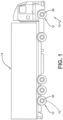
- each one of the tires 12 on the vehicle 14 may include one or more of the tread wear sensor plugs 10. While the vehicle 14 is depicted as a commercial truck, the present disclosure is not to be so restricted. To this end, the vehicle 14 may comprise other vehicles falling into various categories such as passenger vehicles, off-the-road vehicles and the like, in which such vehicles are supported by more or fewer tires than shown in FIG. 1 .
- the tire 12 includes a pair of bead areas 16, each one of which is formed with a bead core 18 that is embedded in the respective bead areas.
- Each one of a pair of sidewalls 20 extends radially outwardly from a respective bead area 16 to a ground-contacting tread 22.
- the tread 22 is formed with multiple tread elements or tread blocks 32 and defines a radially outer surface 34.
- the tire 12 is reinforced by a carcass 24 that toroidally extends from one bead area 16 to the other bead area.
- An innerliner 26 is formed on the inner or inside surface of the carcass 24.
- the tire 12 is mounted on the flange of a wheel or rim 36 ( FIG. 1 ) forming an internal cavity 30.
- a sensor unit 28 is mounted to the tire 12.
- the sensor unit 28 detects certain real-time parameters of the tire 12, and preferably includes a pressure sensor to sense the inflation pressure within a cavity 30 of the tire 12, and a temperature sensor to sense the temperature of the tire 12 and/or the temperature in the cavity 30 of the tire 12.
- the sensor unit 28 may be a commercially-available tire pressure monitoring system (TPMS) module or sensing unit.
- TPMS tire pressure monitoring system
- the sensor unit 28 comprises a processor and memory to store tire identification (ID) information for each specific tire 12.
- the tire ID may include manufacturing information for the tire 12, including the tire model; size information, such as rim size, width, and outer diameter; manufacturing location; manufacturing date; a treadcap code that includes or correlates to a compound identification; a mold code that includes or correlates to a tread structure identification, or other information.
- the tire ID may also include a service history or other information to identify specific features and parameters of each tire 12.
- the sensor unit 28 further includes an antenna for wirelessly transmitting 40 ( FIG. 8 ) measured parameters and tire ID data to a remote processor for analysis, such as a processor integrated into a vehicle electronic control unit and/or a Controller Area Network (CAN) bus associated with the vehicle 14 ( FIG. 1 ).
- a remote processor for analysis such as a processor integrated into a vehicle electronic control unit and/or a Controller Area Network (CAN) bus associated with the vehicle 14 ( FIG. 1 ).
- CAN Controller Area Network
- the sensor unit 28 may be mounted to the tire 12 using a container 38, which receives the sensor unit 28 and is attached to the innerliner 26 by an adhesive, although the sensor unit 28 may be attached in some other manner or may be integrally molded as part of the innerliner 26 of the tire 12.
- the container 38 is flexible and is formed of an elastomer or polymer.
- the sensor unit 28 may be attached to the tire 12 before a channel 42 ( FIG. 6 ) for a tread wear sensor plug 44 ( FIG. 5 ) is formed in a selected tread element 32.
- a removable spacer 46 preferably is disposed between the sensor unit 28 and a base 48 of the container 38, which seats against the innerliner 26.
- the sensor unit 28 includes a rigid housing 50 formed with a base 52.
- a pair of electrical contacts 54 are mounted on the base 52 and extend through the housing 50.
- the tread wear plug 44 includes a shaft 56 and a flange 58.
- the shaft 56 is cylindrical in shape although a cross section of the shaft 56 may be rectangular, hexagonal, octagonal, triangular, or any other shape or form.
- the flange 58 extends outwardly from an end of the shaft 56 to provide a base for the tread wear plug 44.
- a conductive wire 60 is disposed in the tread wear plug 44.
- the wire 60 preferably is an insulated wire, but may be an uninsulated wire, depending on particular design considerations.
- the wire is formed in a U-shape and thus has proximal ends 62 in the flange 58 and a distal end 64 near a radially outer surface 66 of the shaft 56.
- the proximal ends 62 of the wire 60 extend to contacts at a bottom 68 or exposed end of the flange 58 and allow the tread wear plug 44 to contact the electrical contacts 54 ( FIG. 4 ) of the sensor unit 28, as will be described below.
- the distal end 64 of the wire 60 is a set distance 70 below the radially outer surface 66 of the shaft 56.
- an elastomeric connector may be positioned between the proximal ends 62 of the wire 60 and the electrical contacts 54 to ensure a reliable electrical connection therebetween over time.
- Such elastomeric connectors are generally commercially available.
- an elastomeric connector may be employed to electrically couple some other electrical contacts associated with the sensor unit 28 other than the electrical contacts 54 to the proximal ends 62.
- various points on a circuit board that makes up part of the sensor unit 28 may be electrically coupled to the proximal ends 62 by way of an elastomeric connector.
- Such elastomeric connector may be compressed between various electrical contact points regardless of the material from which such electrical contact points are constructed.
- the materials may comprise metal, carbon fiber, conductive rubber compositions, or other materials.
- the analytical estimation of electrical resistance is noted in the graph below.
- a channel 42 for the tread wear plug 44 is formed in a selected tread element 32.
- the container 38 is formed with a sensor unit opening 72, which enables the sensor unit 28 to be removed from the container and thus removably mounted to the tire 12.
- An opening 74 is formed in the container base 48 in alignment with the channel 42 in the tread element 32.
- the aligned channel 42 and opening 74 pass radially from an inner surface of the internal cavity 30 of the tire 12 to the radially outer surface 34 of the tread 22.
- the channel 42 and opening 74 may be formed by drilling, water jet cutting, laser cutting, and or other method.
- the tread wear plug 44 is installed in the tire 12 before the tire 12 is mounted on the wheel 36.
- the shaft 56 of the tread wear plug 44 is inserted from the direction of the cavity 30 through the aligned container opening 74 and into the channel 42 in the tread element 32.
- the shaft 56 extends through the channel 42 in the tread element 32, with the shaft outer surface 66 being flush with the outer surface 34 of the tread element 32.
- the shaft 56 is formed of a material that includes mechanical properties, such as shear modulus, which are similar to those of the material of the tread 22. Such similarity ensures that there are no rigid components within the structure of the tire 12, thereby enabling the shaft 56 of the tread wear plug 44 to behave like a compatible plug in the tread element 32.
- the flange 58 of the tread wear plug 44 preferably is of an elastomeric material that is compatible with the container 38. Once the shaft 56 is inserted into the container base opening 74 and the channel 42, the flange 58 engages the base 48 of the container 38 to provide a positive mechanical stop for the tread wear plug 44. The flange 58 also provides a seal the container base opening 74 to prevent air flow from the tire cavity 30 out through the opening 74 and the channel 42.
- the sensor unit 28 is reinstalled.
- the sensor unit 28 is inserted into the container 38 through the sensor unit opening 72. Because the container 38 is formed of a flexible material, a wall 76 and lip 78 flex to allow insertion of the sensor unit 28, and then secure the sensor unit in the container 38.
- the sensor unit 28 is rotated to enable each sensor electrical contact 54 to contact a respective proximal end 62 of the plug wire 60.
- FIGS. 7 and 8 operation of the tire with a tread wear plug 10 is shown.
- the tread wear plug 44 is installed in the tire 12, and the shaft outer surface 66 is flush with the tread element outer surface 34.
- a continuous electrical circuit is formed by the wire 60 and the contact of each proximal wire end 62 with each respective electrical contact 54 of the sensor unit 28.
- the distal end 64 of the wire 60 is disposed at a predetermined distance 70 ( FIG. 5 ) below the radially outer surface 66 of the shaft 56, which corresponds to a minimum recommended tread depth.
- the shaft 56 of the wear plug 44 also wears.
- the distal end 64 of the wire 60 breaks, creating a break in the electrical circuit formed by the wire and the contact of each proximal wire end 62 with each respective sensor unit electrical contact 54.
- the sensor unit 28 senses the break in the electrical circuit, and wirelessly transmits 40 a notice 86 that the electrical circuit has broken and/or that a predefined minimum tread depth has been reached.
- Th predefined minimum tread depth comprises a minimum recommended tread depth of the tire 12.
- the notice 86 transmitted 40 by the sensor unit 28 may be sent to a remote processor, such as a processor that is integrated into a vehicle electronic control unit, CAN bus, and/or a cloud-based server.
- a remote processor such as a processor that is integrated into a vehicle electronic control unit, CAN bus, and/or a cloud-based server.
- the notice 86 by communicating that the minimum tread depth has been reached, thus indicates when replacement or retreading of the tire 12 should take place.
- the tire with a tread wear plug 10 indicates tire wear with components that are mounted within the tire 12 and does not require sensors that are external to the tire.
- the tire 12 with a tread wear plug 10 provides a direct wear sensor system for a vehicle tire 12 that includes a structure which is easy to install in the tire 12, withstands the operating environment of the tire 12, accurately indicates tire wear in a repeatable manner, and is capable of transmitting a wear indication to an electronic control system of the vehicle 14.
- the present disclosure also includes a method of determining wear of a tire using a tread wear sensor plug 10, and a method of forming a tire with a tread wear sensor plug 10 for indicating tread depth.
- Each method includes steps in accordance with the description that is presented above and shown in FIGS. 1 through 8 .
- a single tread wear plug 44 may be disposed in the tread 22 of the tire 12, or multiple tread wear plugs may be disposed in the tread the tire.
- the tread wear plug 44 may be inserted into the tread element 32 before or after curing of the tire 12.
- the tread wear plug 44 may include multiple wires 60, each one having a distal end 64 spaced apart from the other wires, which enables the tread wear plug to indicate different wear states of the tread 22, without affecting the overall concept or operation of the various embodiments.
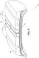
- the tire 103 includes a tread 106 comprising multiple tread elements 109.
- the tread 106 is positioned adjacent to, and radially outward relative to, an undertread 113.
- the tire 103 includes a pair of sidewalls 20 ( FIG. 2 ), where each one of the sidewalls 20 extend radially outwardly from a respective bead to the tread 106.
- the tire 103 also includes a belt package 116 positioned radially inwardly relative to the undertread 113.
- the tire 103 includes a carcass with an innerliner and other components as can be appreciated.
- the tire 103 also includes a chimney 119 that extends from the undertread 113 to the radially outer surface 123 of the tire 103 defined by the tread 106.
- the chimney 119 includes a chimney outer surface 126 that is generally flush with the radially outer surface 123 of the tire 103 and respective tread elements 106 in which the chimney 119 is disposed.
- the chimney 119 is shown in FIG. 9 as positioned within a single tread element 106, it is understood that the chimney 119 may run through multiple tread elements 106.
- Various tires 103 are manufactured with the goal of achieving a predefined resistance from the hub upon which a tire 103 is installed to the ground.
- the tire 103 may be installed on a test hub and the tire 103 may be placed on a metal plate under load at a predefined internal pressure and a desired temperature.
- the resistance presented by the tire may be measured from the hub to the metal plate upon which the tire 103 is placed.
- a higher value of resistance is acceptable where such tires may include a resistance of less than 10 M ⁇ or other appropriate resistance value.
- it may be desirable that the resistance of a given tire to ground may be less than 1 M ⁇ .
- the undertread 113 is constructed from a rubber material which provides for a degree of conductivity.
- the undertread 113 may be constructed from the materials that provide for a tire resistance of less than 10 M ⁇ , 1 M ⁇ , or other desired tire resistance as mentioned above. Given the fact that the undertread 113 is conductive, electrical current is able to flow through such material.
- the undertread 113 is electrically coupled to the metal hub upon which the tire 103 is mounted through conductive elements of the sidewalls 20 ( FIG. 2 ) and other components of the tire 103 as can be appreciated.
- the chimney 119 may be constructed from a conductive rubber composition as is described in the appendix of the present disclosure.
- the conductive rubber composition comprises, for example, a rubber component and one or more electrically conductive carbon components.
- the conductive rubber composition has an uncured or cured electrical resistance at 23°C less than 10K ⁇ when formed into a wire 254 mm long and 2 mm in diameter. Given these parameters, various actual measurements of the resistance of such conductive rubber compositions include 1.3 K ⁇ , 4,4 K ⁇ , and 5.5 K ⁇ . According to one embodiment, the resistivity of the chimney 119 is much less than the resistivity of the undertread 113.
- the resistivity of such conductive rubber composition may be, for example, 7.7 Ohm-centimeters or other value of a similar order as compared to materials that might have a resistivity be below 7.0 ⁇ 10 5 Ohm-centimeters.
- the resistivity of an acceptable rubber composition may have a resistivity that is one or two more orders of magnitude greater than 7.7 ⁇ 10 1 Ohm-centimeters as can be appreciated.
- the chimney 119 establishes a conductive pathway from the conductive undertread 113 to the ground upon which the vehicle travels.
- the ground includes all elements upon which a vehicle may travel including pavement, cement, steel (bridges) dirt, rocks, or any other elements as can appreciated.
- the term ground as contemplated herein refers to an electrical ground as well as a physical ground upon which a vehicle rests.
- the tire 103 includes a conductive pathway established with conductive materials from the hubs of a vehicle through the sidewalls 20 to the undertread 113.
- the chimney 119 completes the circuit by providing a conductive pathway from the undertread 113 to the terrestrial medium upon which the vehicle travels.
- the chimney 119 provides a conductive pathway through the tread 106 through which such a static charge can be discharged to ground. This prevents the buildup of large static charges in the vehicle relative to the ground.
- a lateral width W of the chimney 119 is specified to provide for a predetermined minimum chimney outer surface area in the footprint of the tire 103. This minimum surface area provides for a pathway from the undertread 113 to ground for effective discharge of an electrostatic charge that builds up in the vehicle relative to the ground.
- the actual width W of the chimney 119 will depend upon the desired tire resistance as will be described.
- the lateral position of the chimney 119 may vary depending on the locations of the tread elements 109 of a given tire 103.
- the chimney 119 is located at a lateral position on the tread 106 so as to maximize the contact between the outer surface of the chimney 119 and the ground.
- the chimney 119 may be positioned so that a center of the chimney 119 coincides with an equatorial plane of the tire 103.
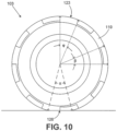
- the chimney 119 comprises an annular chimney that extends circumferentially 360 degrees around the entire periphery of the tire 103. In this manner, at least a portion of an annular chimney is always within a footprint 126 of the tire 103, thereby establishing constant and uninterrupted contact with the ground.
- the chimney 119 may extend circumferentially around at least a portion of the tread 106.
- angular sections noted by angle ⁇ in which the chimney 119 extends from the undertread 113 to the radially outer surface 123 of the tire 103 are angular voids noted by angle ⁇ in which the chimney 119 is omitted.
- a further angle ⁇ is defined by the edges of the footprint 126 that provide a maximum circumferential distance across the footprint 126 of the tire 103.
- the angle ⁇ of the angular voids between the angular sections of the chimney 119 is less than the angle ⁇ of the maximum circumferential distance of the footprint 126 of the tire 103. This ensures that an electrical pathway between the undertread 113 and ground through the chimney 119 is continuous with the rotation of the tire 103.
- an uncured split tread may be mated with a center chimney section that alternates between respective materials to create the angular sections noted by angle ⁇ in which the chimney 119 extends from the undertread 113.
- the tire 130 is similar to the tire 103, where components that both embodiments have in common are indicated using the same reference numbers.
- the tire 130 includes a channel 133 that extends through a tread element 109 of the tread 106.
- the tire 130 includes a conductive insert 136 that comprises a shaft 139 that includes a flange 143 at one end.
- the flange 143 extends outwardly from the end of the shaft 139 to provide a base for the conductive insert 136.
- the conductive insert 136 is placed into the channel 133 such that an outer surface 146 of the shaft 139 is flush with the radially outer surface 123 of a respective tread element 109. In this manner, the conductive insert 136 extends from the undertread 113 through the channel to the radially outer surface 123 of a respective tread element 109 of the tread 106. As such, the radially outermost surface of the conductive insert 136 is flush with the outer surface of a respective tread element 109 of the tread 106.
- the tire 130 includes a pair of sidewalls 20 ( FIG. 2 ), where each one of the sidewalls 20 extend radially outwardly from a respective bead to the tread 106.
- the undertread 113 is constructed from a material that provides for a degree of conductivity to allow electrical current to flow through such material. This makes the undertread 113 a conductive component of the tire 130.
- the undertread 113 is positioned radially inward relative to the radially outer surface 123 of the tread 106.
- the undertread 113 is electrically coupled to the metal hub upon which the tire 130 is mounted through conductive elements of the sidewalls 20 and other components of the tire 103 as can be appreciated.
- the conductive insert 136 is constructed from a conductive rubber composition as described in the appendix of the present disclosure.
- the conductive rubber composition comprises, for example, a rubber component and one or more electrically conductive carbon components.
- the conductive rubber composition has an uncured or cured electrical resistance at 23°C less than 10K ⁇ when formed into a wire 254 mm long and 2 mm in diameter. Given these parameters, various actual measurements of the resistance of such conductive rubber compositions include 1.3 K ⁇ , 4,4 K ⁇ , and 5.5 K ⁇ . Consequently, the resistivity of the conductive insert 136 is much less than the resistivity of the undertread 113.
- the resistivity of such conductive rubber composition may be, for example, 7.7 Ohm-centimeters or other value of a similar order as compared to materials that might have a resistivity be below 7.0 ⁇ 10 5 Ohm-centimeters.
- the resistivity of an acceptable rubber composition may have a resistivity that is one or two more orders of magnitude greater than 7.7 ⁇ 10 1 Ohm-centimeters as can be appreciated.
- the flange 143 of the conductive insert 136 is positioned so as to come into contact with the material of the undertread 143. In one embodiment, the flange 143 displaces a portion of the undertread 143. By virtue of the contact between the flange 143 and the undertread 143, the conductive insert 136 establishes an electrical pathway from the undertread 113 to the radially outer surface 123 of the tread 106.
- the channel 133 may be formed in a respective tread element 109 before or after the tread 106 has been cured and placed on the tire 130 during assembly. Also, a void shaped like the flange 143 is created in the undertread 113 to accommodate the flange 143. A center axis of the void is in alignment with a center axis of the channel 133 through the respective tread element 109 so as to accommodate the entire conductive insert 136.
- the conductive insert 136 When placed in the tread 106 of the tire 130, the conductive insert 136 establishes a conductive pathway from the conductive undertread 113 to the ground upon which the vehicle travels. Given that the tire 103 includes a conductive pathway established with conductive materials from the hubs of a vehicle through the sidewalls 20 to the undertread 113, the conductive insert 136 completes the circuit by providing a conductive pathway from the undertread 113 to the ground upon which the vehicle travels when the conductive insert 136 falls within the footprint of the tire 130. In this manner, the conductive insert 136 facilitates the discharge of a static charge that builds up in the vehicle relative to the ground as the vehicle travels in a manner similar to the chimney 119 ( FIG. 9 ) discussed above.
- the size and shape of the shaft 139 may be specified so that the radially outer surface of the conductive insert 136 is large enough such that the ultimate resistance presented by the conductive insert 136 is low enough to facilitate a satisfactory discharge to ground.
- the conductive insert 136 may be placed at any position where a tread element 109 exists on the tread 106. That is to say that the conductive insert 136 may be located at any position laterally on the tread 106 with the exception that there must be space for the flange 143 relative to a side edge of the undertread 113 if the conductive insert 136 is placed near an edge of the tread 106. As an illustration, the conductive insert 136 may be placed at positions 149a-d.
- a plurality of conductive inserts 136 may be included in a single tire 130. In such case, each individual one of such conductive inserts 136 may be placed at various positions on a given tread 106 of the tire 130.
- the conductive inserts 136 are positioned circumferentially around the tread 106 at even intervals. As shown in FIG. 12 , an angle ⁇ is defined between any two adjacent conductive inserts 136. Also, an angle ⁇ is defined by the edges of the footprint 126 that provide a minimum circumferential distance across the footprint 126 of the tire 103. According to one embodiment, the angle ⁇ is less than the angle ⁇ so as to ensure that one of the conductive inserts 136 falls within the footprint at any given time. This ensures that constant and uninterrupted electrical contact is maintained between the undertread 113 ( FIG. 11 ) and the ground through a respective one of the conductive inserts 136.
- a given tire 103 may only include a single conductive insert 136 and electrostatic discharge may substantially occur once each revolution of the tire 103 when such conductive insert 136 falls into the footprint of a tire 103.
- the conductive inserts 103 may be used to establish intermittent contact between inner conductive elements of the tire 103 and the ground.
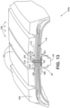
- FIG. 13 shown is a cross sectional view of a portion of a tire 150a according to various embodiments.
- the tire 150a is similar to the tire 103, where components that both tires 103 and 150a have in common are indicated using the same reference numbers.
- the tire 150a includes a tread 106 comprising multiple tread elements 109.
- the tread 106 is positioned adjacent to, and radially outward relative to, an undertread 113.
- the tire 150a includes a pair of sidewalls 20 ( FIG. 2 ), where each one of the sidewalls 20 extend radially outwardly from a respective bead to the tread 106.
- the tire 103 also includes a belt package 116 positioned radially inwardly relative to the undertread 113.
- the tire 150a also includes a carcass with an innerliner and other components as can be appreciated.
- the tire 150a includes a channel 153 that extends from an inside surface of the tire 150a through a least a portion of one of the tread elements 109.
- a tread wear plug 156 having a shaft 159 is positioned in the channel 153.
- a flange 163 extends outwardly from one end of the shaft 159 to provide a base for the tread wear plug 156.
- the tire 150a includes the sensor unit 28 that is held in the container 38 as was discussed with respect to FIGS. 1-8 above.
- the tread wear plug 156 further includes a conductor 166 embedded in the shaft 159. Each of the ends of the conductor 166 terminate into a corresponding sensor contact 169 in the flange 163. Each sensor contact 169 is exposed on an open end of the flange 163.
- the conductor 166 and the sensor contacts 169 are constructed from the conductive rubber composition described in the appendix included in the present disclosure. Alternatively, the conductor 166 and sensor contacts 169 may be constructed from carbon fiber or other material with similar properties.
- the conductive rubber composition comprises, for example, a rubber component and one or more electrically conductive carbon components.
- the conductive rubber composition has an uncured or cured electrical resistance at 23°C less than 10K ⁇ when formed into a wire 254 mm long and 2 mm in diameter. Given these parameters, various actual measurements of the resistance of such conductive rubber compositions include 1.3 K ⁇ , 4,4 K ⁇ , and 5.5 K ⁇ .
- the resistivity of such conductive rubber composition may be, for example, 7.7 Ohm-centimeters or other value of a similar order as compared to materials that might have a resistivity be below 7.0 ⁇ 10 5 Ohm-centimeters.
- the resistivity of an acceptable rubber composition may have a resistivity that is one or two more orders of magnitude greater than 7.7 ⁇ 10 1 Ohm-centimeters as can be appreciated.
- the portion of the shaft 159 in which the conductor 166 is embedded is constructed from a material with properties similar to the properties of the tread 106 of the tire 150a. In one embodiment, this material is nonconductive to electrically isolate the conductor 166 from other portions of the tire 150a such as the belt package 116. Alternatively, the material of the shaft 159 may have a very high resistivity as compared to the resistivity of the conductor 166 such that the material will not interfere with the ability to detect a lack of continuity in the conductor 166 as will be described. The material may comprise any one of various rubber compositions having suitable characteristics for use in the tire 150a.
- the tire 150a includes a predefined minimum tread depth 173. As a tire 150a is put into service on a vehicle over time, the tread 106 will wear down.
- the predefined minimum tread depth 173 is a minimum recommended tread depth at which the tire 150a can be placed into service. Once the tread 106 wears below the predefined minimum tread depth 173, then the tire 150a should be taken out of service.
- the tread 106 of the tire 150a thus includes a sacrificial portion 176 that is expected to wear away over time while the tire 150a is in service.
- the conductor 166 includes a radially outermost portion 179 that is positioned at a predefined depth with respect to the outer surface of the tread element 109 of the tread 106.
- this radially outermost portion 179 is positioned within the sacrificial portion 176 of the tread 106 such that when the entire radially outermost portion 179 is worn away, the continuity of the conductor 166 is compromised and detected by the sensor unit 28 as described above.
- the radially outermost portion 179 of the conductor 166 may be positioned at any depth in the tread 106 so as to detect wear of the tread 106 at various heights.
- the radially outermost portion 179 of the conductor 166 is positioned relative to the predefined minimum tread depth 173 such that when the radially outermost portion 179 of the conductor 166 has worn away, the tread 106 will have been worn down to the predefined minimum tread depth 173.
- the sensor unit 28 can thus detect when the tire 150a has reached maximum wear and should be taken out of service.
- the sensor unit 28 includes a pair of electrical contacts 54 that are mounted on the base 52 ( FIG. 4 ) and extend through the housing 50 ( FIG. 4 ).
- the sensor unit 28 comprises an electrically active sensor as described above.
- each of the electrical contacts 54 are in direct contact with a corresponding one of the sensor contacts 169 in the tread wear plug 156.
- the sensor contacts 169 exposed on the open end of the flange 163 are constructed from the conductive rubber composite material, the flexibility of the material ensures solid electrical contact between the sensor contacts 169 of the tread wear plug 156 and the electrical contacts 54 of the sensor unit 28.
- the sensor unit 28 is held by the container 38 such that the electrical contacts 54 are pressed or driven into the sensor contacts 169 to ensure that electrical contact between the electrical contacts 54 and the sensor contacts 169, respectively, is maintained while the tire 150a is in service.
- FIG. 14 shown is a cross sectional view of a portion of a tire 150b according to various embodiments.
- the tire 150b is essentially the same as the tire 150a ( FIG. 13 ), where reference numbers for like components are the same for both figures.
- the tire 150b is essentially the same as the tire 150a except for the fact that the channel 183 extends from the inside surface of the tire 150b to a radially outer surface 123 of a respective one of the tread elements 109 of the tread 106.
- the shaft 186 of the tread wear plug 181 extends through the entire channel 183 such that the radially outermost surface 189 of the shaft 186 is flush with the radially outermost surface 123 of a given tread element 109 of the tread 106.
- the radially outermost surface 189 is flush with the radially outermost surface of a tread element 109 into which the tread wear plug 181 is disposed.
- the tread wear plugs 156 or 181 may be located at any lateral position on the tread 106 of the tire 150a/150b.
- the tread wear plug 181 may be placed at positions 193a-e or any other position on the tread 106 in a given tread element 109 as shown.
- the tread wear plugs 156/181 may be positioned to detect tread wear at any lateral location on the tread 106 of a tire 150a/150b.
- the radial outermost portion 179 of the conductor 166 may be positioned at various predefined depths with respect to the radial outer surface 123 of a given tread element 109 to detect different levels of wear of the tread 106. For example, it may be desirable to detect different levels of wear of a tread 106 at different lateral locations on the tread 106.
- a tread wear plug 156/181 may be positioned to intersect an equatorial plane of a tire 150a/150b.
- a tread wear plug 156/181 may be positioned such that a first distance between a channel 153/183 and a lateral edge of the tread 106 may be greater than a second distance between a channel 153/183 and the equatorial plane of the tire 150a/150b.
- a distance between the channel 153/183 and an equatorial plane of the tire 150a/150b may be greater than a distance between the channel 153/183 and a lateral edge of the tread 106.
- the tread wear sensor plug 196 includes a shaft 203 that is to be positioned in a channel 183 as will be described.
- the shaft 203 includes an electrostatic discharge portion 203a and a tread wear sensor portion 203b.
- the electrostatic discharge portion 203a of the shaft 203 includes an inner channel 206 that may be shaped so as to receive a portion of the tread wear sensor portion 203b as will be described. Also, in one embodiment, a flange 209 extends from a radially innermost end of the electrostatic discharge portion 203a of the shaft 203. However, in another embodiment, the flange 209 may be omitted.
- the electrostatic discharge portion 203a of the shaft 203 is constructed from the conductive rubber composition which comprises, for example, a rubber component and one or more electrically conductive carbon components.
- the conductive rubber composition has an uncured or cured electrical resistance at 23°C less than 10K ⁇ when formed into a wire 254 mm long and 2 mm in diameter.
- the tread wear sensor portion 203b includes a tread sensor extension 213 that protrudes from a radially outermost end of the tread wear sensor portion 203b.
- the tread sensor extension 213 is shaped so as to fit within the inner channel 206 of the electrostatic discharge portion 203a.
- the electrostatic discharge portion 203a and the tread wear sensor portion 203b together comprise the entire shaft 203 of the tread wear sensor plug 196.
- a flange 216 extends from a radially innermost end of the tread wear sensor portion 203b.
- the electrostatic discharge portion 203a may be placed into a portion of the channel 183 that extends through the tread 106 before the tread 106 is applied to a tire 220.
- the tread 106 may be in a cured or uncured state when the electrostatic discharge portion 203a is positioned in the portion of the channel 183 extending through the tread 106.
- the portion of the channel 183 that extends through the tread 106 would be positioned so as to align with the portion of the channel 183 extending through the remaining components of the tire 220 including the undertread 113, belt package 116, inner lining, and potentially other components.
- FIG. 15B shown is a cutaway view of a portion of a tire 220 that illustrates the tread wear sensor plug 196 of FIG. 15A placed in a channel 183.
- the tire 220 includes many of the elements of the tire 150b ( FIG. 14 ), where reference numbers for like components are the same for both structures.
- the tread wear sensor plug 196 includes the conductor 166 embedded within the tread wear sensor portion 203b.
- the material of the tread wear sensor portion 203b is constructed from a material with properties similar to the properties of the tread 106 of the tire 220. In one embodiment, this material is nonconductive to electrically isolate the conductor 166 from other portions of the tire 220 such as the belt package 116.
- the material of the tread wear sensor portion 203b may have a very high resistivity as compared to the resistivity of the conductor 166 such that the material will not interfere with the ability to detect a lack of continuity in the conductor 166.
- the material may comprise any one of various rubber compositions having suitable characteristics for use in the tire 220.
- the tire 200 includes the channel 183 that extends from the inner surface of the tire 200 to the radially outermost surface 123 ( FIG. 14 ) of the tire 200.
- the channel 183 extends through various components such as a belt package 116, the undertread 113, and other components of the tire 200.
- the conductor 166 extends into the tread sensor extension 213 such that the radially outermost portion 179 of the conductor 166 is positioned so as to detect a predefined amount of tread wear of the tire 220.
- the sensor unit 28 detects the discontinuity in the conductor 166 and signals that the tread 106 of the tire 166 has reached the minimum level of tread needed for safe vehicle operation. In this manner, an operator of the vehicle is warned that the tire needs to be replaced.
- the conductor 166 is embedded within the tread wear sensor portion 203 so as that the point of wear of the tread 106 that triggers the warning to the operator is a point in which the conductor 166 will be worn away such that a discontinuity in the conductor 166 occurs.
- the conductor 166 may comprise the conductive rubber composition described in the attached appendix which comprises, for example, a rubber component and one or more electrically conductive carbon components.
- the conductive rubber composition has an uncured or cured electrical resistance at 23°C less than 10 K ⁇ when formed into a wire 254 mm long and 2 mm in diameter.
- the conductor 166 and sensor contacts 169 may be constructed from carbon fiber or other material with similar properties.
- the ends of the conductor 166 terminate into sensor contacts 169.
- the sensor unit 28 includes a pair of electrical contacts 54.
- the electrical contacts 54 are in direct contact with a corresponding one of the sensor contacts 169 in the tread wear plug 156 as was mentioned above.
- the sensor contacts 169 exposed on the open end of the flange 163 are constructed from the conductive rubber composite material, the flexibility of the material ensures solid electrical contact between the sensor contacts 169 of the tread wear plug 156 and the electrical contacts 54 of the sensor unit 28.
- the sensor unit 28 is held by the container 38 such that the electrical contacts 54 are pressed or driven into the sensor contacts 169 to ensure that electrical contact between the electrical contacts 54 and the sensor contacts 169, respectively, is maintained while the tire 150a is in service.
- the electrostatic discharge portion 203a may or may not include the flange 209.
- the flange 209 is optional.
- the electrostatic discharge portion 203a is in direct contact with, or electrically coupled to, a conductive component such as an undertread 113 of the tire 220.
- the shaft portion of the electrostatic discharge portion 203a may be in direct contact with, or electrically coupled to such conductive component such as the undertread 113.
- FIG. 15C shown is a cutaway view taken across section line AA depicted in FIG. 15B .
- the material of the tread sensor extension 213 surrounds the conductor 166 ( FIG. 15B ), where section line AA cuts through the center of the radially outermost portion 179 of the conductor 166.
- the conductor 166 is electrically isolated from the electrostatic discharge portion 203a of the shaft 203. In one embodiment, the conductor 166 may actually come into electrical contact with the electrostatic discharge portion 203a.
- the portion of the electrostatic discharge portion 203a that coincides with the tread sensor extension 213 may have a larger diameter or cross sectional surface area to ensure enough cross sectional area exists for this section so that resistance of the electrostatic discharge portion 203a is not increased such that the ultimate tire resistance does not meet a given target resistance.
- the channel 183 may be made larger or of a different shape in this region to accommodate the larger cross sectional surface area of the electrostatic discharge portion 203a in this section.
- the tread wear sensor plug 196 may be used in place of one of the conductive inserts 136 ( FIG. 11 ).
- a tire 130 FIG. 11
- at least one tread wear sensor plug 196 may be used along with the conductive inserts 136.
- one or more tread wear sensor plugs 196 may be used in place of a conductive insert 136 in positions where it is desirable to provide for tread wear sensing on a given tire 130.
- FIGS. 9-12 and 15A-C shown are various embodiments that include a chimney 119, a conductive insert 136, or the tread wear sensor plug 196 that includes the electrostatic discharge portion 203a, where the electrostatic discharge portion 203a acts in a similar manner to the conductive insert 126. It is understood that these various mechanisms may be employed to achieve a desired tire resistance for a given tire.
- disjunctive language such as the phrase "at least one of X, Y, or Z," unless specifically stated otherwise, is otherwise understood with the context as used in general to present that an item, term, etc., may be either X, Y, or Z, or any combination thereof (e.g., X, Y, and/or Z).
- disjunctive language is not generally intended to, and should not, imply that certain embodiments require at least one of X, at least one of Y, or at least one of Z to each be present.
- conductive rubber compositions including a rubber component and one or more electrically conductive carbon compounds.
- the conductive rubber compositions can be prepared by first adding the one or more conductive carbon components into the polymer phase, thereby creating a filler network in the continuous polymer phase in the finished product.
- the conductive carbon component can be or include one or more of the following: carbon black, a short carbon fiber, graphite powder, or graphene powder.
- the conductive rubber compositions can optionally be vulcanized.
- the conductive rubber compositions have acceptable mechanical properties and conductivity and can be processed using existing equipment.
- the conductive rubber compositions disclose herein include a rubber component.
- the rubber component can be natural rubber (NR), polyisoprene rubber (IR), a styrene butadiene rubber (SBR), a polybutadiene rubber (BR), a butyl or halobutyl rubber, an ethylene propylene rubber (EM), an ethylene-propylene diene rubber (EPDM), polychloroprene rubber (CR), a nitrile butadiene rubber (NBR) hydrogenated acrylonitrile butadiene rubber (HNBR), a silicone rubber (MQ), a thermoplastic rubber, or any combination thereof.
- NR natural rubber
- IR polyisoprene rubber
- SBR styrene butadiene rubber
- BR polybutadiene rubber
- CR butyl or halobutyl rubber
- EM ethylene propylene rubber
- EPDM ethylene-propylene diene rubber
- CR polychlor
- the butyl or halobutyl rubber can be isobutylene-isoprene rubber (IIR), brominated isobutylene-isoprene rubber (BIIR), chlorinated isobutylene-isoprene rubber (CIIR), brominated isobutylene-co-p-methylstyrene rubber (BIMS), or any combination thereof.
- the thermoplastic rubber can be a poly(styrene-butadiene-styrene) rubber (SBS), a thermoplastic elastomeric rubber (TPE), a melt-processable rubber (MPR), or any combination thereof.
- the thermoplastic elastomeric rubber can be a thermoplastic polyurethane rubber.
- the conductive rubber composition includes a blend of two or more rubber components.
- an electrically conductive system based on polymer blends can achieve a high electrical conductivity with lower filler content, thus alleviating difficulties with blending the carbon compounds in the polymers and reducing materials costs.
- the rubber component can have a molecular weight (M w ) of from 5 ⁇ 10 4 Da to 3 ⁇ 10 7 Da, or from 3 ⁇ 10 5 Da to 5 ⁇ 10 6 Da, or of 5 ⁇ 10 4 Da, 6 ⁇ 10 4 Da, 7 ⁇ 10 4 Da, 8 ⁇ 10 4 Da, 9 ⁇ 10 4 Da, 1 ⁇ 10 5 Da, 2 ⁇ 10 5 Da, 3 ⁇ 10 5 Da, 4 ⁇ 10 5 Da, 5 ⁇ 10 5 Da, 6 ⁇ 10 5 Da, 7 ⁇ 10 5 Da, 8 ⁇ 10 5 Da, 9 ⁇ 10 5 Da, 1 ⁇ 10 6 Da, 2 ⁇ 10 6 Da, 3 ⁇ 10 6 Da, 4 ⁇ 10 6 Da, 5 ⁇ 10 6 Da, 6 ⁇ 10 6 Da, 7 ⁇ 10 6 Da, 8 ⁇ 10 6 Da, 9 ⁇ 10 6 Da, 1 ⁇ 10 7 Da, 2 ⁇ 10 7 Da, or 3 ⁇ 10 7 Da, or a combination of any of the foregoing values, or a range
- the rubber component can have a molecular weight distribution (M w /M n ) of from 1 to 10, or from 2.1 to 10, or from 3.9 to 8.2, or of 1, 1.25, 1.5, 1.75, 2, 2.1, 2.25, 2.5, 2.75, 3, 3.25, 3.5, 3.75, 4, 4.25, 4.5, 4.75, 5, 5.25, 5.5, 5.75, 6, 6.25, 6.5, 6.75, 7, 7.25, 7.5, 7.75, 8, 8.25, 8.5, 8.75, 9, 9.25, 9.5, 9.75, or 10, or a combination of any of the foregoing values, or a range encompassing any of the foregoing values.
- M w /M n molecular weight distribution
- the rubber component has a Mooney viscosity UML of from 0.01 to 150, or of 0.01, 0.05, 0.1, 0.5, 1, 2, 5, 10, 15, 20, 25, 30, 35, 40, 45, 50, 55, 60, 65, 70, 75, 80, 85, 90, 95, 100, 105, 110, 115, 120, 125, 130, 135, 140, 145, or 150, or a combination of any of the foregoing values, or a range encompassing any of the foregoing values.
- the rubber component has a Mooney viscosity UMS of from 2 to 150, or of 2, 5, 10, 15, 20, 25, 30, 35, 40, 45, 50, 55, 60, 65, 70, 75, 80, 85, 90, 95, 100, 105, 110, 115, 120, 125, 130, 135, 140, 145, or 150, or a combination of any of the foregoing values, or a range encompassing any of the foregoing values.
- the rubber component has a glass transition temperature of from -110°C to 30°C, or from -75°C to -25°C, or of -110, -105, -100, -95, -90, -85, -80, -75, -70, -65, -60, -55, -50, -45, -40, -35, -30, -25, -20, -15, -10, -5, 0, 5, 10, 15, 20, 25, or 30°C, or a combination of any of the foregoing values, or a range encompassing any of the foregoing values.
- the rubber component includes a natural rubber having a molecular weight of from 3 ⁇ 10 4 Da to 3 ⁇ 10 7 Da and a glass transition temperature of from -75°C to -65°C.
- the rubber component includes a synthetic cis-1,4-polyisoprene rubber having a molecular weight of from 2 ⁇ 10 5 Da to 8 ⁇ 10 5 Da, a Mooney viscosity UML of preferably 75, and a glass transition temperature of from -70°C to -60°C.
- the rubber component includes an emulsion-polymerized styrene-butadiene rubber having a molecular weight of from 1 ⁇ 10 5 Da to 4 ⁇ 10 5 Da, a Mooney viscosity of 50 UML, and a glass transition temperature of from -60°C to -50°C.
- the rubber component includes a solution-polymerized styrene-butadiene rubber having a molecular weight of from 7 ⁇ 10 4 Da to 8 ⁇ 10 4 Da, a Mooney viscosity UML of 2.6, and a glass transition temperature of from -30°C to -20°C.
- TSR20 Natural Rubber
- RSS Natural Rubber NATSYN 2200
- PLF1502 Exp SBR
- Exp SBR Exp SBR
- TSR20 Technicalnically Specified Rubber
- UML Mooney viscosity
- RSS Ribbed Smoked Sheet Rubber
- UMS Mooney viscosity
- NATSYN 2200 (Goodyear Chemical, Akron OH) is a synthetic high cis polyisoprene containing a non-staining antioxidant and having a T g of -64°C, an M n of 2.04 ⁇ 10 5 Da, an M w of 7.31 ⁇ 10 3 Da, a molecular weight distribution of 3.575, and a Mooney viscosity (UML) of 75.
- PLF1502 (PLIOFLEX 1502, Goodyear Chemical, Akron OH) is an emulsion polymerized styrene-butadiene copolymer (23.5% styrene, 12% vinyl, 55% trans, 10% cis) having a T g of -55°C, an M n of 1.01 ⁇ 10 5 Da, an M w of 4.03 ⁇ 10 5 Da, a molecular weight distribution of 3.99, and a Mooney viscosity (UML) of 50, with a non-staining antioxidant.
- PLF1502 PIOFLEX 1502, Goodyear Chemical, Akron OH
- Exp SBR is an experimental Li-solution based styrene-butadiene rubber having a T g of -26°C, an M n of 7.39 ⁇ 10 4 Da, an M w of 7.39 ⁇ 10 4 Da, a molecular weight distribution of 1.00, and a Mooney viscosity (UML) of 2.63.
- the conductive rubber compositions disclosed herein include an electrically conductive carbon component.
- Exemplary conductive carbon components are described below.
- the one or more carbon components can be present in an amount of from 20 phr to 150 phr, or of from 30 phr to 100 phr, or of from 40 phr to 80 phr, or at 20, 30, 40, 50, 60, 70, 80, 90, 100, 110, 120, 130, 140, or 150 phr, or a combination of any of the foregoing values, or a range encompassing any of the foregoing values.
- the electrically conductive carbon component can be or include a carbon black.
- the carbon black can have an average particle size of from 5 nm to 100 nm, or from 5 nm to 50 nm, or of 5, 10, 15, 20, 25, 30, 35, 40, 45, 50, 55, 60, 65, 70, 75, 80, 85, 90, 95, or 100 nm, or a combination of any of the foregoing values, or a range encompassing any of the foregoing values.
- the carbon black can have a BET surface area of from 20 m 2 /g to 1700 m 2 /g, or of from 50 m 2 /g to 1500 m 2 /g, or of 20, 50, 100, 200, 300, 400, 500, 600, 700, 800, 900, 1000, 1100, 1200, 1300, 1400, 1500, 1600, or 1700 m 2 /g, or a combination of any of the foregoing values, or a range encompassing any of the foregoing values.
- the carbon black can have an external surface area based on statistical thickness method (STSA) of from 20 to 1200 m 2 /g, or 100 m 3 /g to 300 m 3 /g, or of from 150 m 3 /g to 200 m 3 /g, or of 20, 25, 50, 75, 100, 125, 150, 175, 200, 225, 250, 275, 300, 350, 400, 450, 500, 550, 600, 650, 700, 750, 800, 850, 900, 950, 1000, 1050, 1100, 1150, or 1200 m 3 /g, or a combination of any of the foregoing values, or a range encompassing any of the foregoing values.
- STSA statistical thickness method
- the carbon black can have an oil absorption number of from 500 mL/100 g to 20 mL/100 g, or from 500 mL/100 g to 80 mL/100 g, or of 500, 450, 400, 350, 300, 250, 200, 150, 100, or 80 mL/100 g, or a combination of any of the foregoing values, or a range encompassing any of the foregoing values.
- Suitable carbon blacks include, but are not limited to, the following: an N299 ASTM grade carbon black, PRINTEX XE2B (Orion Engineered Carbons, Luxembourg), PROPEL X22 (Cabot Corporation, Boston MA), or any combination thereof.
- PRINTEX XE2B has an oil absorption number of 410 mL/100 g as measured by standard test method ASTM D 2414, a BET surface area of 1100 m 2 /g as measured by ASTM D 6556, and an average primary particle size of 30 nm based on ASTM D 3849.
- PROPEL X22 has iodine of 230 mg/g according to standard test method ASTM D 1510, external surface area based on statistical thickness method (STSA) of 173 m 2 /g according to standard test method ASTM D6556, compressed sample oil absorption number (COAN) of 100 mL/100g according to standard test method ASTM D3493, and a tint of 150% ITRB according to standard test method ASTM D 3265.
- STSA statistical thickness method
- COAN compressed sample oil absorption number
- Additional useful carbon blacks include BLACK PEARLS 2000 carbon black and Vulcan XC-72 (BOTH FROM Cabot Corporation, Boston MA), CONDUCTEX 975 and CONDUCTEX SC (Columbian Chemicals, Hamilton ON Canada), and PRINTEX XE2, PRINTEX L, AND PRINTEX L6 (Orion Engineered Carbons, Germany).
- the electrically conductive carbon component can be or include a short carbon fiber.
- the short carbon fiber can be a carbon fiber, chopped carbon fiber yarn, multi-walled carbon nanotubes (MWCNTs), single-walled carbon nanotubes (SWCNTs), or any combination thereof.
- the short carbon fiber has a diameter of from 1 nm to 1000 nm, or of from 150 nm to 600 nm, or of 1, 10, 25, 50, 100, 150, 200, 250, 300, 350, 400, 450, 500, 550, 600, 650, 700, 750, 800, 850, 900, 950, or 1000 nm, or a combination of any of the foregoing values, or a range encompassing any of the foregoing values.
- the short carbon fiber can have a length of from 1 ⁇ m to 1 ⁇ 10 4 ⁇ m, or of 1, 100, 500, 1000, 2000, 3000, 4000, 5000, 6000, 7000, 8000, 9000, or 10,000 ⁇ m, or a combination of any of the foregoing values, or a range encompassing any of the foregoing values.
- the short carbon fiber can have an average lateral length to thickness ratio of from 10:1 to 10,000:1, or of 10:1, 50:1, 100:1, 500:1, 1000:1, 2000:1, 3000:1, 4000:1, 5000:1, 6000:1, 7000:1, 8000:1, 9000:1, or 10,000:1, or a combination of any of the foregoing values, or a range encompassing any of the foregoing values.
- An exemplary short carbon fiber useful herein has a diameter of from 150 to 600 nm depending on the grade, a BET surface area of from 120-190 m 2 /g and a length of greater than 1 ⁇ m.
- the carbon component can include a blend.
- the one or more carbon components consists of a blend of carbon black and graphite powder, or of carbon black and graphene powder.
- the one or more carbon components includes a blend of carbon black and a short carbon fiber.
- the inclusion of a blend carbon black and short carbon fibers may provide additional advantages in terms of conductivity of the mixtures.
- the carbon black can improve interfiber contacts by forming particle bridges, while carbon fibers can aid the transport of electrons over long distances, thus establishing a continuous pathway for electrical conduction in the disclosed compositions.
- including a blend of carbon black and a short carbon fiber may result in the formation of a different conductive network structure in a blend of polymers versus a rubber composition based on a single polymer.
- the short carbon fiber can be from 5 phr to 80 phr, or from 20 phr to 40 phr, or can be 5, 10, 15, 20, 25, 30, 35, 40, 45, 50, 55, 60, 65, 70, 75, or 80 phr, or a combination of any of the foregoing values, or a range encompassing any of the foregoing values
- the carbon black can be from 15 phr to 70 phr, or from 10 phr to 60 phr, or 10, 15, 20, 25, 30, 35, 40, 45, 50, 55, 60, 65, or 70 phr, or a combination of any of the foregoing values, or a range encompassing any of the foregoing values.
- the electrically conductive carbon component can include an ASTM N299 grade carbon black and a short carbon fiber having a diameter of from 1 nm to 1000 nm and a length of from 1 ⁇ m to 1 ⁇ 10 4 ⁇ m.
- the electrically conductive carbon component can include a carbon black having an oil absorption number of 100 mL/100 g and a short carbon fiber having a diameter of from 1 nm to 1000 nm and a length of from 1 ⁇ m to 1 ⁇ 10 4 ⁇ m.
- the electrically conductive carbon component can include a carbon black having an average particle size of 30 nm and a short carbon fiber having a diameter of from 1 nm to 1000 nm and a length of from 1 ⁇ m to 1 ⁇ 10 4 ⁇ m.
- the conductive rubber compositions disclosed herein can additionally contain one or more additional components in addition to those already described.
- the additional component can be selected from antioxidants and/or antiozonants, oils, zinc oxide, fatty acids, sulfur, an accelerator, a retarder, and combinations thereof.
- the conductive rubber compositions disclosed herein include at least one antioxidant, at least one anti-ozonant, or any combination thereof.
- an antiozonant can protect the rubber compositions from ozone (Os).
- the antiozonant can be a material such as a wax that travels to the surface of a rubber article to protect the article against attack from ozone. Suitable examples of antiozonant include, but are not limited to, Antiozite 67P (Vanderbilt Chemicals, LLC, Norwalk CT USA).
- the antioxidant is a non-staining antioxidant.
- the antioxidant can be an amine antioxidant, a diphenylamine antioxidant, a polymeric dihydroquinoline, or any combination thereof.
- the antioxidant or antiozonant can be present in an amount of from 1 phr to 2 phr in the compositions, or at 1, 1.1, 1.2, 1.3, 1.4, 1.5, 1.6, 1.7, 1.8, 1.9, or 2 phr, or a combination of any of the foregoing values, or a range encompassing any of the foregoing values.
- the conductive rubber compositions include an oil.
- the oil is a standard rubber processing oil, such as, for example, an aromatic rubber process oil, a paraffinic rubber process oil, a naphthenic rubber process oil, or any combination thereof.
- the rubber process oil can improve the dispersion of fillers and flow characteristics of the rubber composition during processing.
- the oil can be present in an amount of from 4 phr to 30 phr, or at 4, 5, 6, 7, 8, 9, 10, 11, 12, 13, 14, 15, 16, 17, 18, 19, 20, 21, 22, 23, 24, 25, 26, 27, 28, 29, or 30 phr, or a combination of any of the foregoing values, or a range encompassing any of the foregoing values.
- the conductive rubber compositions disclosed herein include zinc oxide.
- zinc oxide is a useful activator for rubber vulcanization.
- the zinc oxide is present in the conductive rubber compositions at from 1 phr to 5 phr, or at 1, 2, 3, 4, or 5 phr, or a combination of any of the foregoing values, or a range encompassing any of the foregoing values.
- the zinc oxide is present in an amount of 3 phr.
- the conductive rubber compositions disclosed herein include a fatty acid.
- the fatty acid can be stearic acid, palmitic acid, oleic acid, or any combination thereof.
- the fatty acid can be present in the conductive rubber compositions in an amount of from 1 phr to 5 phr, or at 1, 1.1, 1.2, 1.3, 1.4, 1.5, 1.6, 1.7, 1.8, 1.9, 2, 2.25, 2.5, 2.75, 3, 3.25, 3.5, 3.75, 4, 4.25, 4.5, 4.75, or 5 phr, or a combination of any of the foregoing values, or a range encompassing any of the foregoing values.
- the conductive rubber compositions disclosed herein include sulfur.
- the sulfur can be present in an amount of from 0.5 to 5 phr, or from 0.5 to 3 phr, or at 0.5, 1, 1.5, 2, 2.5, 3, 3.5, 4, 4.5, or 5 phr, or a combination of any of the foregoing values, or a range encompassing any of the foregoing values.
- the sulfur is present in an amount of 1.8 phr.
- sulfur can be useful for forming crosslinks between rubber chains during the vulcanization process.
- the conductive rubber compositions include an accelerator.
- the accelerator can be a sulfenamide sulfur cure accelerator.
- the accelerator is present in an amount of from 0.5 to 5 phr, or from 1 to 2 phr, or at 0.5, 1, 1.5, 2, 2.5, 3, 3.5, 4, 4.5, or 5 phr, or a combination of any of the foregoing values, or a range encompassing any of the foregoing values.
- the accelerator is present at 1.2 phr.
- the conductive rubber compositions include a retarder.
- the retarder can be N-(cyclohexylthio)phthalimide.
- the retarder can be present in an amount of from 0.05 to 0.5 phr, or from 0.1 phr to 0.3 phr, or at 0.05, 0.1, 0.15, 0.2, 0.25, 0.3, 0.35, 0.4, 0.45, or 0.5 phr, or a combination of any of the foregoing values, or a range encompassing any of the foregoing values.
- the retarder can be useful for preventing premature vulcanization during rubber processing.
- An exemplary retarder can be Vantard PVI (Vanderbilt Chemicals, LLC, Norwalk CT USA).
- the disclosed conductive rubber compositions can be made by mixing one or more additives into the rubber or polymeric base of the rubber compositions. In a further aspect, heating the rubber or polymeric base of the rubber compositions softens the rubber or polymeric base enough to allow for the mixing of additives into the rubber composition.
- the additives are discussed herein and include one or more of an antioxidant or antiozonant, oil, zinc oxide, fatty acid, sulfur, accelerator, retarder, and one or more conductive carbon components.
- the additives can be mixed into the rubber compositions sequentially or simultaneously.
- a masterbatch can be prepared containing nonreactive additives such as the conductive carbon component, to ensure thorough mixing of the conductive carbon component prior to the beginning of vulcanization.
- vulcanization additives e.g., sulfur, zinc oxide
- the rubber compositions may further be shaped prior to or during the early stages of vulcanization by a method including, but not limited to, extrusion, calendaring, molding, casting, another rubber processing method, or any combination thereof.
- processing aids can be used, such as, for example, waxes including but not limited to microcrystalline and paraffinic waxes, in a range, for example, of from 1 phr to 5 phr, or from 1 phr to 3 phr, or at 1, 2, 3, 4, or 5 phr, or a combination of any of the foregoing values, or a range encompassing any of the foregoing values, if used.
- waxes including but not limited to microcrystalline and paraffinic waxes
- resins usually as tackifiers
- the tackifiers or resins are compounds such as, for example, synthetic hydrocarbon and natural resins in a range of, for example, from 1 phr to 5 phr or from 1 phr to 3 phr, or at 1, 2, 3, 4, or 5 phr, or a combination of any of the foregoing values, or a range encompassing any of the foregoing values, if used.
- a curative can be present as sulfur together with one or more sulfur cure accelerator(s).
- the amount of sulfur used can be, for example, from 0.5 phr 5 phr, or from 0.5 to 3 phr, or at 0.5, 1, 1.5, 2, 2.5, 3, 3.5, 4, 4.5, or 5 phr, or a combination of any of the foregoing values, or a range encompassing any of the foregoing values; and the accelerator(s), often of the sulfenamide type, is (are) used in a range of from 0.5 phr to 5 phr, or from 1 phr to 2 phr, or at 0.5, 1, 1.5, 2, 2.5, 3, 3.5, 4, 4.5, or 5 phr, or a combination of any of the foregoing values, or a range encompassing any of the foregoing values.
- components of the compositions are normally first mixed together in a series of at least two sequential mixing stages, although sometimes one mixing stage might be used, to a temperature in a range of, for example, 145°C to 185°C, or at 145, 150, 155, 160, 165, 170, 175, 180, or 185°C, or a combination of any of the foregoing values, or a range encompassing any of the foregoing values, and such mixing stages are typically referred to as non-productive mixing stages.
- the sulfur and accelerators, and optionally one or more retarders and optionally one or more antidegradants are mixed therewith to a temperature of, for example, from 90°C to 120°C, or at 90, 95, 100, 105, 110, 115, or 120°C, or a combination of any of the foregoing values, or a range encompassing any of the foregoing values, in a second stage that is typically referred as a productive mix stage.
- a temperature of, for example, from 90°C to 120°C, or at 90, 95, 100, 105, 110, 115, or 120°C, or a combination of any of the foregoing values, or a range encompassing any of the foregoing values.
- the disclosed conductive rubber composition can have an uncured storage modulus at 15% train, 100°C, and 0.83 Hz, of from 185 kPa to 1100 kPa, or of 185, 200, 300, 400, 500, 600, 700, 800, 900, 1000, or 1100 kPa, or a combination of any of the foregoing values, or a range encompassing any of the foregoing values.
- the uncured storage modulus can be measured using a rubber process analyzer.
- the disclosed conductive rubber compositions can have a storage modulus at 1% strain, 100°C, and 11 Hz of from 1.1 MPa to 4 MPa, or of 1.1, 1.5, 2, 2.5, 3, 3.5, or 4 MPa, or a combination of any of the foregoing values, or a range encompassing any of the foregoing values.
- the disclosed conductive rubber compositions can have a storage modulus at 10% strain, 100°C, and 11 Hz of from 0.8 MPa to 3 MPa, or of 0.8, 1, 1.2, 1.4, 1.6, 1.8, 2, 2.2, 2.4, 2.6, 2.8, or 3 MPa, or a combination of any of the foregoing values, or a range encompassing any of the foregoing values.
- the disclosed conductive rubber compositions can have a storage modulus at 50% strain, 100°C, and 11 Hz of from 0.35 MPa to 1 MPa, or of 0.35, 0.4, 0.5, 0.6, 0.7, 0.8, 0.9, or 1 MPa, or a combination of any of the foregoing values, or a range encompassing any of the foregoing values.
- storage modulus can be measured using a rubber process analyzer.
- the disclosed conductive rubber compositions can have a 10% modulus of from 0.4 MPa to 2.5 MPa, or of 0.4, 0.5, 1, 1.5, 2, or 2.5 MPa, or a combination of any of the foregoing values, or a range encompassing any of the foregoing values.
- the disclosed conductive rubber compositions can have a 50% modulus of from 1.25 MPa to 3.5 MPa, or of 1.25, 1.5, 2, 2.5, 3, or 3.5 MPa, or a combination of any of the foregoing values, or a range encompassing any of the foregoing values.
- the disclosed conductive rubber compositions can have a 100% modulus of from 2 MPa to 5.2 MPa, or of 2, 2.5, 3, 3.5, 4, 4.5, 5, or 5.2 MPa, or a combination of any of the foregoing values, or a range encompassing any of the foregoing values.
- the disclosed conductive rubber compositions can have a 200% modulus of from 3 MPa to 12 MPa, or of 3, 4, 5, 6, 7, 8, 9, 10, 11, or 12 MPa, or a combination of any of the foregoing values, or a range encompassing any of the foregoing values.
- the disclosed conductive rubber compositions can have a 300% modulus of from 4 MPa to 13.5 MPa, or of 4, 5, 6, 7, 8, 9, 10, 11, 12, 13, or 13.5 MPa, or a combination of any of the foregoing values, or a range encompassing any of the foregoing values.
- the modulus can be measured using a tensile test based on ASTM D 412.
- the conductive rubber compositions disclosed herein can have a tensile strength of above 2 MPa, or of from 2 MPa to 30 MPa, or of 2, 2.5, 3, 3.5, 4, 4.5, 5, 10, 15, 20, 25, or 30 MPa, or a combination of any of the foregoing values, or a range encompassing any of the foregoing values.
- tensile strength can be measured using a tensile test based on ASTM D 412.
- the conductive rubber compositions disclosed herein can have an elongation at break of above 200%, or of from 200% to 800%, or of 200, 250, 300, 350, 400, 450, 500, 550, 600, 650, 700, 750, or 800%, or a combination of any of the foregoing values, or a range encompassing any of the foregoing values.
- elongation at break can be measured using a tensile test based on ASTM D 412.
- the conductive rubber compositions disclosed herein can be formed into a wire.
- the wire can be 254 mm long and 2 mm in diameter.
- such a wire can have a cured or uncured electrical resistance at 23°C of from 5 ohms ( ⁇ ) to 10 megaohms (M ⁇ ), or from 5 ⁇ to an upper limit of 100 kiloohms (k ⁇ ), or of 5, 25 ⁇ , 50 ⁇ , 75 ⁇ , 100 ⁇ , 200 ⁇ , 300 ⁇ , 400 ⁇ , 500 ⁇ , 600 ⁇ , 700 ⁇ , 800 ⁇ , or 900 ⁇ , or 1 k ⁇ , 5 k ⁇ , 10 k ⁇ , 20 k ⁇ , 30 k ⁇ , 40 k ⁇ , 50 k ⁇ , 60 k ⁇ , 70 k ⁇ , 80 k ⁇ , 90 k ⁇ , 100 k ⁇ , 200 k ⁇ , 300 k ⁇ , 400 k ⁇ , 500 k ⁇ , 600 k ⁇ , 700 k ⁇ ,
- electrical resistance can be measured using a standard multimeter.
- the conductive rubber compositions have a resistivity of less than 800 ⁇ m, or 10, 50, 100, 150, 200, 250, 300, 350, 400, 450, 500, 550, 600, 650, 700, 750, or 800 ⁇ m, or a combination of any of the foregoing values, or a range encompassing any of the foregoing values.
- conductivity and/or resistance of the conductive rubbers is enhanced in the disclosed compositions when the surface area, particle size, and structure (e.g. porosity) of the carbon component are higher.
- the conductive rubber compositions disclosed herein can have a T25 as measured using a moving die rheometer standard test at 150°C for 60 min of from 1 min to 30 min, or of 1, 2, 3, 4, 5, 6, 7, 8, 9, 10, 11, 12, 13, 14, 15, 16, 17, 18, 19, 20, 21, 22, 23, 24, 25, 26, 27, 28, 29, or 30 min, or a combination of any of the foregoing values, or a range encompassing any of the foregoing values.
- the conductive rubber compositions disclosed herein can have a T90 as measured using a moving die rheometer standard test at 150°C for 60 min of from 5 min to 60 min, or of 5, 10, 15, 20, 25, 30, 35, 40, 45, 50, 55, or 60 min, or a combination of any of the foregoing values, or a range encompassing any of the foregoing values.
- T25 and T90 can be measured using a rubber process analyzer and/or a moving die rheometer standard test (using ASTM D 5289 and/or ISO 6502).
- the conductive rubber compositions can have a Zwick rebound at 23°C of from 30 to 60, or of 30, 35, 40, 45, 50, 55, or 60, or a combination of any of the foregoing values, or a range encompassing any of the foregoing values.
- the conductive rubber compositions can have a Zwick rebound at 100°C of from 45 to 75, or of 45, 50, 55, 60, 65, 70, or 75, or a combination of any of the foregoing values, or a range encompassing any of the foregoing values.
- Zwick rebound can be measured using standard test methods DIN 53512 for elastomers and rubber, ISO 4662 for rubber, or BS 903.
- the disclosed conductive rubber compositions have a final torque measured at 150°C for 60 min of from 10 dN ⁇ m to 45 dN ⁇ m, or of 10, 15, 20, 25, 30, 35, 40, or 45 dN ⁇ m, or a combination of any of the foregoing values, or a range encompassing any of the foregoing values.
- final torque can be measured using a moving die rheometer to perform testing according to ASTM D 5289 and/or ISO 6502.
- the disclosed conductive rubber compositions have a 2 point reversion time measured at 150°C for 60 minutes of from 0.1 min to 40 min, or of 0.1, 0.5, 1, 5, 10, 15, 20, 25, 30, 35, or 40 min, or a combination of any of the foregoing values, or a range encompassing any of the foregoing values.
- 2 point reversion time can be measured using a moving die rheometer to perform testing according to ASTM D 5289 and/or ISO 6502.
- an article including the conductive rubber compositions disclosed herein.
- the article can be a tire, a tire chimney, a wire, a sensor, a hose, an electromagnetic interference shielding gasket, a weather sealing material, an adhesive, or any combination thereof.
- the conductive rubber compositions described herein possess excellent electrical resistance properties while using lower amounts of the carbon component.
- the compositions also possess good mechanical properties, which reduces the degradation rate of the articles made therefrom (e.g., tire).
- the articles incorporating the conductive compositions described herein possess good electrical and mechanical properties.
- a conductive rubber composition comprising a rubber component and one or more electrically conductive carbon components, wherein the conductive rubber composition has an uncured or cured electrical resistance at 23°C less than 10 M ⁇ when formed into a wire 10 254 mm long and 2 mm in diameter.
- Aspect 2 The conductive rubber composition of aspect 1, wherein the rubber component comprises natural rubber (NR), polyisoprene rubber (IR), a styrene butadiene rubber (SBR), a polybutadiene rubber (BR), a butyl or halobutyl rubber, an ethylene propylene rubber (EM), an ethylene-propylene diene rubber (EPDM), polychloroprene rubber (CR), a nitrile butadiene rubber (NBR) hydrogenated acrylonitrile butadiene rubber (HNBR), a silicone rubber (MQ), a thermoplastic rubber, or any combination thereof.
- NR natural rubber
- IR polyisoprene rubber
- SBR styrene butadiene rubber
- BR polybutadiene rubber
- CR butyl or halobutyl rubber
- EM ethylene propylene rubber
- EPDM ethylene-propylene diene rubber
- CR polychloroprene rubber
- Aspect 3 The conductive rubber composition of aspect 2, wherein the butyl or halobutyl rubber comprises isobutylene-isoprene rubber (IIR), brominated isobutylene-isoprene rubber (BIIR), chlorinated isobutylene-isoprene rubber (CIIR), brominated isobutylene-co-p-methylstyrene rubber (BIMS), or any combination thereof.
- IIR isobutylene-isoprene rubber
- BIIR brominated isobutylene-isoprene rubber
- CIIR chlorinated isobutylene-isoprene rubber
- BIMS brominated isobutylene-co-p-methylstyrene rubber
- thermoplastic rubber comprises a poly(styrene-butadiene-styrene) rubber (SBS), a thermoplastic elastomeric rubber (TPE), a melt-processable rubber (MPR), or any combination thereof.
- SBS poly(styrene-butadiene-styrene) rubber
- TPE thermoplastic elastomeric rubber
- MPR melt-processable rubber
- thermoplastic elastomeric rubber comprises a thermoplastic polyurethane rubber (TPU).
- Aspect 6 The conductive rubber composition of any one of aspects 2-5, wherein the conductive rubber composition comprises a blend of two or more rubber components.
- Aspect 7 The conductive rubber composition of any one of the preceding aspects, wherein the rubber component comprises a molecular weight (M w ) of from 5 ⁇ 10 4 Da to 3 ⁇ 10 7 Da.
- Aspect 8 The conductive rubber composition of any one of the preceding aspects, wherein the rubber component comprises a molecular weight (M w ) of from 3 ⁇ 10 5 Da to 5 ⁇ 10 6 Da.
- Aspect 9 The conductive rubber composition of any one of the preceding aspects, wherein the rubber component comprises a Mooney viscosity UML of from 0.01 to 150.
- Aspect 10 The conductive rubber composition of any one of the preceding aspects, wherein the rubber component comprises a Mooney viscosity UMS of from 2 to 150.
- Aspect 11 The conductive rubber composition of any one of the preceding aspects, wherein the rubber component comprises a glass transition temperature of from -110°C to -30°C.
- Aspect 12 The conductive rubber composition of any one of the preceding aspects, wherein the rubber component comprises a glass transition temperature of from -75°C to -30°C.
- Aspect 13 The conductive rubber composition of any one of the preceding aspects, wherein the one or more electrically conductive carbon components comprise carbon black, a short carbon fiber, graphite powder, graphene powder, or any combination thereof.
- Aspect 14 The conductive rubber composition of any one of the preceding aspects, wherein the one or more carbon components are present in amount of from 20 phr to 150 phr.
- Aspect 15 The conductive rubber composition of aspect 14, wherein the one or more carbon components are present in an amount of from 30 phr to 100 phr.
- Aspect 16 The conductive rubber composition of aspect 14, wherein the one or more carbon components are present in an amount of from 40 phr to 80 phr.
- Aspect 17 The conductive rubber composition of any one of aspects 13-16, wherein the one or more carbon components comprise carbon black having an average particle size of from 5 nm to 100 nm.
- Aspect 18 The conductive rubber composition of aspect 17, wherein the one or more carbon components comprise carbon black having an average particle size of from 5 nm to 50 nm.
- Aspect 19 The conductive rubber composition of any one of the preceding aspects, wherein the rubber component comprises a molecular weight distribution (M w /M n ) of from 2.1 to 10.
- Aspect 20 The conductive rubber composition of any one of the preceding aspects, wherein the rubber component comprises a molecular weight distribution (M w /M n ) of from 3.9 to 8.2.
- Aspect 21 The conductive rubber composition of any one of aspects 13-20, wherein the one or more carbon components comprise carbon black having a BET surface area of from 20 m 2 /g to 1700 m 2 /g.
- Aspect 22 The conductive rubber composition of aspect 21, wherein the one or more carbon components comprise carbon black having a BET surface area of from 50 m 2 /g to 1500 m 2 /g.
- Aspect 23 The conductive rubber composition of any one of aspects 13-22, wherein the one or more carbon components comprise carbon black having an external surface area based on statistical thickness method (STSA) of from 20 m 3 /g to 1200 m 3 /g.
- STSA statistical thickness method
- Aspect 24 The conductive rubber composition of aspect 23, wherein the one or more carbon components comprise carbon black having an external surface area based on statistical thickness method (STSA) of from 100 m 3 /g to 300 m 3 /g.
- STSA statistical thickness method
- Aspect 25 The conductive rubber composition of any one of aspects 13-24, wherein the one or more carbon components comprise carbon black having an oil absorption number (OAN) of from 500 mL/100 g to 80 mL/100 g.
- OAN oil absorption number
- Aspect 26 The conductive rubber composition of aspect 25, wherein the one or more carbon components comprise carbon black having an oil absorption number (OAN) of from 500 mL/100 g to 100 mL/100 g.
- OAN oil absorption number
- Aspect 27 The conductive rubber composition of any one of aspects 13-26, wherein the short carbon fiber comprises a carbon fiber, chopped carbon fiber yarn, multi-walled carbon nanotubes (MWCNTs), single-walled carbon nanotubes (SWCNTs), or any combination thereof.
- MWCNTs multi-walled carbon nanotubes
- SWCNTs single-walled carbon nanotubes
- Aspect 28 The conductive rubber composition of aspect 27, wherein the short carbon fiber has a diameter of from 1 nm to 1000 nm.
- Aspect 29 The conductive rubber composition of aspect 28, wherein the short carbon fiber has a diameter of from 150 nm to 600 nm.
- Aspect 30 The conductive rubber composition of any one of aspects 27-29, wherein the short carbon fiber has a length of from 1 ⁇ m to 1 ⁇ 10 4 ⁇ m.
- Aspect 31 The conductive rubber composition of any one of aspects 28-30, wherein the short carbon fiber has an average lateral length to thickness ratio of from 10:1 to 10,000:1.
- Aspect 32 The conductive rubber composition of any one of aspects 13-31, wherein the one or more carbon components comprise a blend of carbon black and graphite powder.
- Aspect 33 The conductive rubber composition of any one of aspects 13-31, wherein the one or more carbon components comprise a blend of carbon black and graphene powder.
- Aspect 34 The conductive rubber composition of any one of aspects 13-31, wherein the one or more carbon components comprise a blend of carbon black and a short carbon fiber.
- Aspect 35 The conductive rubber composition of aspect 34, wherein, in the blend, the short carbon fiber is from 5 phr to 80 phr and the carbon black is from 15 phr to 70 phr.
- Aspect 36 The conductive rubber composition of aspect 34, wherein, in the blend, the short carbon fiber is from 20 phr to 40 phr and the carbon black is from 10 phr to 60 phr.
- Aspect 37 The conductive rubber composition of any one of the preceding aspects, further comprising at least one antioxidant, at least one antiozonant, or any combination thereof.
- Aspect 38 The conductive rubber composition of aspect 37, wherein the antioxidant comprises an amine antioxidant, a diphenylamine antioxidant, a polymeric dihydroquinoline, or any combination thereof.
- Aspect 39 The conductive rubber composition of aspect 37 or 38, wherein the antioxidant is present in an amount of from 1 phr to 2 phr.
- Aspect 40 The conductive rubber composition of any one of the preceding aspects, further comprising at least one additional component selected from an oil, zinc oxide, a fatty acid, sulfur, an accelerator, a retarder, or any combination thereof.
- Aspect 41 The conductive rubber composition of aspect 40, wherein the oil comprises an aromatic rubber process oil, a paraffinic rubber process oil, a naphthenic rubber process oil, or any combination thereof.
- Aspect 42 The conductive rubber composition of aspect 40 or 41, wherein the oil is present in an amount of from 4 phr to 30 phr.
- Aspect 43 The conductive rubber composition of aspect 40, wherein the zinc oxide is present in an amount of 3 phr.
- Aspect 44 The conductive rubber composition of aspect 40, wherein the fatty acid comprises stearic acid, palmitic acid, oleic acid, or any combination thereof.
- Aspect 45 The conductive rubber composition of aspect 40 or 44 wherein the fatty acid is present in an amount of from 1 phr to 5 phr.
- Aspect 46 The conductive rubber composition of aspect 40, wherein the sulfur is present in an amount of from 0.5 phr to 5 phr.
- Aspect 47 The conductive rubber composition of aspect 40, wherein the accelerator comprises a sulfenamide.
- Aspect 48 The conductive rubber composition of aspect 40 or 47, wherein the accelerator is present in an amount of from 0.5 phr to 5 phr.
- Aspect 49 The conductive rubber composition of aspect 40, wherein the retarder comprises N-(cyclohexylthio)phthalimide.
- Aspect 50 The conductive rubber composition of aspect 40 or 49, wherein the retarder is present in an amount of from 0.05 phr to 0.5 phr.
- Aspect 51 The conductive rubber composition of any one of aspects 1-50, wherein the rubber component comprises a natural rubber having a molecular weight of from 3 ⁇ 10 4 Da to 3 ⁇ 10 7 Da and a glass transition temperature of from -75°C to -65°C.
- Aspect 52 The conductive rubber composition of any one of aspects 1-50, wherein the rubber component comprises a synthetic cis-1,4-polyisoprene rubber having a molecular weight of from 2 ⁇ 10 5 Da to 8 ⁇ 10 5 Da, a Mooney viscosity UML of 75, and a glass transition temperature of from -70°C to -60°C.
- the rubber component comprises a synthetic cis-1,4-polyisoprene rubber having a molecular weight of from 2 ⁇ 10 5 Da to 8 ⁇ 10 5 Da, a Mooney viscosity UML of 75, and a glass transition temperature of from -70°C to -60°C.
- Aspect 53 The conductive rubber composition of any one of aspects 1-50, wherein the rubber component comprises an emulsion-polymerized styrene-butadiene rubber having a molecular weight of from 1 ⁇ 10 5 Da to 4 ⁇ 10 5 Da, a Mooney viscosity of 50 UML, and a glass transition temperature of from -60°C to - 50°C.
- the rubber component comprises an emulsion-polymerized styrene-butadiene rubber having a molecular weight of from 1 ⁇ 10 5 Da to 4 ⁇ 10 5 Da, a Mooney viscosity of 50 UML, and a glass transition temperature of from -60°C to - 50°C.
- Aspect 54 The conductive rubber composition of any one of aspects 1-50, wherein the rubber component comprises a solution-polymerized styrene-butadiene rubber having a molecular weight of from 7 ⁇ 10 4 Da to 8 ⁇ 10 4 Da, a Mooney viscosity UML of 2.6, and a glass transition temperature of from -30°C to - 20°C.
- the rubber component comprises a solution-polymerized styrene-butadiene rubber having a molecular weight of from 7 ⁇ 10 4 Da to 8 ⁇ 10 4 Da, a Mooney viscosity UML of 2.6, and a glass transition temperature of from -30°C to - 20°C.
- Aspect 55 The conductive rubber composition of any one of aspects 1-50, wherein the electrically conductive carbon component comprises a carbon black having an average particle size of from 5 nm to 100 nm.
- Aspect 56 The conductive rubber composition of any one of aspects 1-50, wherein the electrically conductive carbon component comprises a carbon black having an average particle size of from 5 nm to 50 nm and an average surface area of from 20 m 2 /g to 1500 m 2 /g.
- Aspect 57 The conductive rubber composition of any one of aspects 1-50, wherein the electrically conductive carbon component comprises an ASTM N299 grade carbon black and a short carbon fiber having a diameter from 1 nm to 1000 nm and a length of from 1 ⁇ m to 1 ⁇ 10 4 ⁇ m.
- Aspect 58 The conductive rubber composition of any one of aspects 1-50, wherein the electrically conductive carbon component comprises a carbon black having an oil absorption number of 100 mL/100g and a short carbon fiber having a diameter of from 1 nm to 1000 nm and a length of from 1 ⁇ m to 1 ⁇ 10 4 ⁇ m.
- Aspect 59 The conductive rubber composition of any one of aspects 1-50, wherein the electrically conductive carbon component comprises a carbon black having an average particle size of 30 nm and a short carbon fiber having a diameter of from 1 nm to 1000 nm and a length of from 1 ⁇ m to 1 ⁇ 10 4 ⁇ m.
- Aspect 60 The conductive rubber composition of any one of the preceding aspects, wherein the conductive rubber composition has an uncured storage modulus at 15% strain, 100°C, and 0.83 Hz of from 185 kPa to 1100 kPa.
- Aspect 61 The conductive rubber composition of any one of the preceding aspects, wherein the conductive rubber composition has a storage modulus at 1% strain, 100°C, and 11 Hz of from 1.1 MPa to 4 MPa.
- Aspect 62 The conductive rubber composition of any one of the preceding aspects, wherein the conductive rubber composition has a storage modulus at 10% strain, 100°C, and 11 Hz of from 0.8 MPa to 3 MPa.
- Aspect 63 The conductive rubber composition of any one of the preceding aspects, wherein the conductive rubber composition has a storage modulus at 50% strain, 100°C, and 11 Hz of from 0.35 MPa to 1 MPa.
- Aspect 64 The conductive rubber composition of any one of the preceding aspects, wherein the conductive rubber composition has a 10% modulus of from 0.4 MPa to 2.5 MPa.
- Aspect 65 The conductive rubber composition of any one of the preceding aspects, wherein the conductive rubber composition has a 50% modulus of from 1.25 MPa to 3.5 MPa.
- Aspect 66 The conductive rubber composition of any one of the preceding aspects, wherein the conductive rubber composition has a 100% modulus of from 2 MPa to 5.2 MPa.
- Aspect 67 The conductive rubber composition of any one of the preceding aspects, wherein the conductive rubber composition has a 200% modulus of from 3 MPa to 12 MPa.
- Aspect 68 The conductive rubber composition of any one of the preceding aspects, wherein the conductive rubber composition has a 300% modulus of from 4 MPa to 13.5 MPa.
- Aspect 69 The conductive rubber composition of any one of the preceding aspects, wherein the conductive rubber composition has a tensile strength of above 2 MPa.
- Aspect 70 The conductive rubber composition of any one of the preceding aspects, wherein the conductive rubber composition has a tensile strength of from 4.5 MPa to 30 MPa.
- Aspect 71 The conductive rubber composition of any one of the preceding aspects, wherein the conductive rubber composition has an elongation at break above 200%.
- Aspect 72 The conductive rubber composition of any one of the preceding aspects, wherein the conductive rubber composition has an elongation at break of from 300 % to 800%.
- Aspect 73 The conductive rubber composition of any one of the preceding aspects, wherein the conductive rubber composition has an electrical resistance at 23°C of from 5 ⁇ to 10 M ⁇ when formed into a wire 254 mm long and 2 mm in diameter when the conductive rubber composition is cured or uncured.
- Aspect 74 The conductive rubber composition of any one of the preceding aspects, wherein the conductive rubber composition has an electrical resistance at 23°C of from 5 ⁇ to 100 k ⁇ when formed into a wire 254 mm long and 2 mm in diameter when the conductive rubber composition is cured or uncured.
- Aspect 75 The conductive rubber composition of any one of the preceding aspects, wherein the conductive rubber composition has a T25 of from 1 min to 30 min when measured using a moving die rheometer standard test at 150°C for 60 min.
- Aspect 76 The conductive rubber composition of any one of the preceding aspects, wherein the conductive rubber composition has a T90 of from 5 min to 60 min when measured using a moving die rheometer standard test at 150°C for 60 min.
- Aspect 77 The conductive rubber composition of any one of the preceding aspects, wherein the conductive rubber composition has a Zwick rebound at 23°C of from 30 to 60.
- Aspect 78 The conductive rubber composition of any one of the preceding aspects, wherein the conductive rubber composition has a Zwick rebound at 100°C of from 45 to 75.
- Aspect 79 The conductive rubber composition of any one of the preceding aspects, wherein the conductive rubber composition has a final torque of from 10 dN ⁇ m to 45 dN ⁇ m when measured at 150°C for 60 min.
- Aspect 80 The conductive rubber composition of any one of the preceding aspects, wherein the conductive rubber composition exhibits a 2 pt reversion time of from 0.1 min to 40 min when measured at 150°C for 60 min.
- Aspect 81 An article comprising the conductive rubber composition of any one of aspects 1-77.
- Aspect 82 The article of aspect 81, wherein the article comprises a tire, a tire chimney, a wire, a sensor, a hose, an electromagnetic interference shielding gasket, a weather sealing material, an adhesive, or any combination thereof.
- Mooney Viscosity ML for a large rotor
- MS for a small rotor
- RPA Rubber Process Analyzer
- MDR Moving Die Rheometer
- a tensile test (Die C) at 23°C based on standard test method ASTM D 412 was used to measure 10%, 50%, 100%, 200%, and 300% modulus, tensile strength, and elongation at break.
- External surface area based on statistical thickness method is measured according to standard test method ASTM D 6556.
- a Fluke 117 True RMS Multimeter was used to measure electrical resistance of uncured rubber wires at 23°C.
- a typical wire used for the test was 254 mm long and 2 mm in diameter. In this test, a result of "OL" indicates an opened line where resistance cannot be measured.
- Zwick rebound at 23°C and 100°C was measured using standard test method DIN 53512 for elastomers and rubber, ISO 4662 (for rubber), and/or BS 903.
- the Glass transition temperature Tg for polymers is determined as a peak midpoint by a differential scanning calorimeter (DSC) at a temperature rate of increase of 10°C per minute, according to ASTM D3418-15 or equivalent.
- Molecular weight refers to the true molecular weight in g/mol of a polymer (copolymer or block of a copolymer). It is measured with gel permeation chromatography (GPC) using polystyrene calibration standards according to ASTM 5296-11 or equivalent. Mn (number average molecular weight), Mw (weight average molecular weight) and Mz (z average molecular weight) can be suitably determined together using said gel permeation chromatography (GPC) according to ASTM 5296-11 using polystyrene calibration standards (for further explanations, please see ASTM 5296-11 and/or Saviour A. Umoren and Moses M. Solomon, Polymer Characterization: Polymer Molecular Weight Distribution, March 2016, in Polymer Science, pages 412-419 , in particular and sections 2 and 3.3.1).
- Example 2 Exemplary Compositions and Properties Thereof
- Exemplary conductive rubber compositions using carbon black as the conductive carbon compound are provided in Table 1.
- Table 1 Exemplary Conductive Rubber Compositions a Component Control A Conductive Rubber Composition #1 #2 #3 #4 #5 TSR20 Natural Rubber b 100 RSS Natural Rubber c 100 Natsyn2200 d 100 PLF1502 e 100 Exp SBR f 100 100 Carbon Black A g 40 Carbon Black C h 50 50 50 50 80 Antioxidants 1 2 2 2 2 2 Oil i 4 20 20 20 20 20 20 30 Zinc Oxide 3 3 3 3 3 3 3 3 3 3 3 3 3 3 3 3 3 3 3 3 3 3 3 3 3 3 3 3 3 3 3 3 3 3 3 3 3 3 Fatty Acid j 2 2 2 2 2 2 2 2 2 2 Sulfur 1.8 1.8 1.8 1.8 1.8 Accelerator(s) k 1.2 1.2 1.2 1.2 1.2 Retarder 0.1 0.1 0.1 0.2 0.2 0.2 a All amounts provided in units of parts per hundred rubber (phr).
- TSR20 Natural Rubber consists primarily of cis-1,4-polyisoprene and has a T g of -70°C with 20% max Dirt.
- c RSS Natural Rubber is a #2 Ribbed Smoked Sheet (#2 RSS) Natural Rubber with T g of -70°C.
- d Natsyn2200 is synthetic cis-1,4-polyisoprene with a T g of -64°C.
- e PLF1502 is an emulsion polymerization of styrene-butadiene rubber having 23.5% styrene, 12% vinyl, 55% trans, 10% cis, and T g of -55°C.
- f Exp SBR is an experimental Li-solution SBR with T g of -26°C.
- Carbon Black A is an N299 ASTM grade carbon black.
- Carbon Black C is commercially available from Orion Engineered Carbons as PRINTEX XE2B.
- the oil is a standard rubber processing oil.
- the fatty acid is a mixture of stearic acid, palmitic acid, and oleic acid.
- the accelerator is a sulfenamide sulfur cure accelerator.
- Table 2 Properties of Exemplary Conductive Rubber Compositions Property Units Control A Conductive Rubber Composition #1 #2 #3 #4 #5 Mooney Viscosity ML 99.2 75 50 2.63 2.63 Mooney Viscosity MS 142 Uncured Storage Modulus (G') at 15% Strain, 100°C, 0.83 Hz kPa 187 527 488 584 358 1099 T25 min 1.43 0.99 0.91 0.91 0.09 0.82 T25 Min 1.82 6.11 7.93 4.88 1.15 2.17 T90 Min 2.17 19.32 21.99 27.57 27.85 21.74 Storage Modulus (G'), 1%, at MPa 1.17 3.18 3.67 3.66 3.40 1.16 100°C, 11 Hz Storage Modulus (G'), 10%, at 100°C, 11 Hz MPa 0.82 1.82 1.90 1.65 1.05 2.55 Storage Modulus (G'), 50%, at 100°C, 11 Hz MPa 0.55 0.97 0.94 0.74 0.
- compositions using a combination of carbon black and a short carbon fiber as the conductive carbon compound are provided in Table 3.
- Table 3 Exemplary Conductive Rubber Compositions a Component b Control B Conductive Rubber Composition #6 #7 #8 Natsyn2200 b 100 100 TSR20 Natural Rubber b 100 100 Carbon Black A b 40 30 Carbon Black B c 40 Carbon Black C b 40 Short Carbon Fiber d 40 40 40 Antioxidants 1 1 1 1 Oil b 4 4 15 22 Zinc Oxide 3 3 3 3 3 3 3 3 3 3 3 3 3 3 3 Fatty Acid b 1 1 1 1 1 1 1 Sulfur 1.8 1.8 1.8 1.8 Accelerator(s) b 1.2 1.2 1.2 1.2 Retarder 0.1 0.1 0.2 0.2 a All amounts provided in units of parts per hundred rubber (phr).
- Carbon Black B is commercially available from Cabot Corporation as PROPEL X22.
- Short carbon fiber has a diameter ranging from 150-600 nm and a length of greater than 1 ⁇ m.
- Table 4 Properties of Exemplary Conductive Rubber Compositions Property Units Control B Conductive Rubber Composition #6 #7 #8 Uncured Storage Modulus (G') at 15% Strain, 100°C, 0.83 Hz kPa 0.187 0.313 0.248 0.596 T25 min 1.43 1.36 1.72 1.56 T25 Min 1.82 1.63 2.01 2.05 T90 Min 2.17 1.95 2.38 2.58 Storage Modulus (G'), 1%, at 100°C, 11 Hz MPa 1.174 1.673 1.977 3.973 Storage Modulus (G'), 10%, at 100°C, 11 Hz MPa 0.818 1.111 0.968 1.504 Storage Modulus (G'), 50%, at 100°C, 11 Hz MPa 0.551 0.685 0.533 0.565 Tan Delta (10%) at 100°C, 1 Hz 0.127 0.155 0.228 0.388 Max Torque dN ⁇ m 16.95
Landscapes
- Engineering & Computer Science (AREA)
- Mechanical Engineering (AREA)
- Tires In General (AREA)
Abstract
Description
- In the manufacture of a pneumatic tire, the tire is typically built on the drum of a tire-building machine, which is known in the art as a tire building drum. Numerous tire components are wrapped and/or applied to the drum in sequence, forming a cylindrical-shaped tire carcass. The tire carcass is then expanded into a toroidal shape for receipt of the remaining components of the tire, such as a belt package and a rubber tread. The completed toroidally-shaped unvulcanized tire carcass, which is known in the art at that stage as a green tire, is then inserted into a mold or press for forming of the tread pattern and curing or vulcanization.
- The use of tread wear indicators that are formed on a tire tread before or after curing is known in the art. For example, prior art mechanical tread wear indicators include color indicia disposed below certain tread elements, tie bars disposed in the tread grooves, or characters formed in the tread elements, all of which provide a visual indicator of wear. Such mechanical indicators may be difficult for a vehicle operator to see, and thus do not easily provide information to the operator.
- In addition, it is often desirable to collect electronic data for the wear state of the tire. The data can be communicated to electronic systems of the vehicle, such as vehicle stability and/or braking systems, in order to provide improved control of the vehicle and to monitor or track driving behavior. Mechanical tread wear indicators are not able to provide such data to electronic systems of the vehicle.
- To provide an indication of tire wear to vehicle electronic systems, prior art indirect wear estimation techniques were developed. Such techniques involve estimation of tire wear through certain tire and vehicle parameters, rather than direct measurement of wear. For example, tire pressure, tire temperature, vehicle speed, vehicle mileage, vehicle acceleration and other parameters may be employed to estimate tire wear. Such indirect estimation of tire wear can be difficult to perform accurately, and typically involves complex modeling techniques.
- In order to provide a wear indication to vehicle electronic systems based on a direct measurement of tire wear, prior art electronic wear sensors were developed. Such sensors are known in the art as direct wear sensors, as they attempt to directly measure tire wear, rather than providing an estimate from indirect means. By way of example, prior art direct wear sensors include resistance-based electronic sensors that typically are incorporated into tread elements of tires. As the tread element wears, resistors in the sensor also wear, leading to a change in the electrical resistance of the sensor. By measuring the resistance of the sensor and transmitting the measured resistance data to a processor, wear of the tread can be determined.
- While prior art direct wear sensors are acceptable for their intended purpose, many such sensors are difficult to install in the tire. Other direct wear sensors cannot withstand the harsh operating environment of the tire for a prolonged period, such as the recommended life of the tire. Still other direct wear sensors are not capable of maintaining precise and repeatable indication of tire wear over the recommended life of the tire.
- The invention relates to a tire in accordance with claim 1 and to a system in accordance with claim 15.
- Dependent claims refer to preferred embodiments of the invention.
- In preferred embodiments of the invention, the predefined depth with respect to the outer surface of the tread element corresponds to a predefined minimum tread depth of the tire.
- In preferred embodiments of the invention, the channel is positioned on an equatorial plane of the tire.
- In a first aspect of the invention, a tire is disclosed comprising a plurality of sidewalls, each one of the sidewalls extending radially outwardly from a respective bead to a tread, the tread comprising a plurality of tread elements; and a tire component positioned in the tire adjacent to the tread and a chimney extending from the tire component through at least one tread element, wherein the tire component and the chimney comprise a rubber composition having an uncured or cured electrical resistance at 23°C less than 10 KΩ when formed into a wire 254 millimeters long and 2 millimeters in diameter.
- In a second aspect of the invention, a tire is disclosed comprising a plurality of sidewalls, each one of the sidewalls extending radially outwardly from a respective bead to a tread, the tread comprising a plurality of tread elements; and a channel extending from a conductive component of the tire to an outer surface of one of the tread elements and a conductive insert positioned in the channel, wherein a radially outermost surface of the conductive insert is flush with an outer surface of the tread element, and wherein the conductive insert is constructed of a conductive rubber composition having an uncured or cured electrical resistance at 23°C less than 10 KΩ when formed into a wire 254 millimeters long and 2 millimeters in diameter.
- In a third aspect of the invention, a tire is disclosed comprising a plurality of sidewalls, each one of the sidewalls extending radially outwardly from a respective bead to a tread, the tread comprising a plurality of tread elements; and a conductive component in the tire, the conductive component being positioned radially inward relative to an outer surface of the tread, and one or a plurality of conductive inserts, wherein individual ones of the one or more conductive inserts contact the conductive component of the tire and extend to an outer surface of at least one of the tread elements, and wherein the conductive insert is constructed of a conductive rubber composition having an uncured or cured electrical resistance at 23°C less than 10 KΩ when formed into a wire 254 millimeters long and 2 millimeters in diameter.
- In a fourth aspect of the invention, a tire is disclosed comprising a plurality of sidewalls, each one of the sidewalls extending radially outwardly from a respective bead to a tread, the tread comprising a plurality of tread elements; and a channel extending from an inside surface of the tire through at least a portion of one of the tread elements and a tread wear plug including a shaft positioned in the channel, wherein a flange extends from a radially innermost end of the shaft; and a conductor embedded in the shaft, the conductor having a pair of ends terminating into a corresponding pair of sensor contacts in the flange, a radially outermost portion of the conductor being positioned at a predefined depth with respect to an outer surface of the tread element, the conductor comprising a conductive rubber composition having an uncured or cured electrical resistance at 23°C less than 10 KΩ when formed into a wire 254 millimeters long and 2 millimeters in diameter and/or the conductor being constructed from carbon fiber;
- In yet another aspect of the invention, a tire tread wear depth sensing system is disclosed, the system comprising a tread wear plug including a shaft configured to be inserted in a channel extending from an inside surface of a tire through at least a portion of one of a plurality of tread elements of the tire, and a conductor embedded in the shaft, the conductor having a pair of ends terminating into a corresponding pair of sensor contacts in a flange positioned at a first end of the shaft, wherein a portion of the conductor is positioned in the shaft at a predefined distance from a second end of the shaft such that the portion of the conductor is disposed in a sacrificial portion of the tread element of the tire when the shaft is fully inserted into the channel, the conductor comprising a conductive rubber composition having an uncured or cured electrical resistance at 23°C less than 10 KΩ when formed into a wire 254 millimeters long and 2 millimeters in diameter.
- Many aspects of the present disclosure can be better understood with reference to the following drawings. The components in the drawings are not necessarily to scale, with emphasis instead being placed upon clearly illustrating the principles of the disclosure. Moreover, in the drawings, like reference numerals designate corresponding parts throughout the several views.
-
FIG. 1 is a drawing of a vehicle with one or more tires that include a tread wear sensor plug according to various embodiments of the present disclosure. -
FIG. 2 is a perspective cross-sectional view of a tire shown inFIG. 1 , prior to installation of the tread wear sensor plug according to various embodiments of the present disclosure. -
FIG. 3 is an enlarged schematic perspective view of a tire shown inFIG. 2 according to various embodiments of the present disclosure. -
FIG. 4 is a perspective view of a TPMS sensor employed in the exemplary embodiment of the tire with a tread wear sensor plug ifFIG. 2 according to various embodiments of the present disclosure. -
FIG. 5 is a cross-sectional view of the tread wear plug employed in the exemplary embodiment of the tire with a tread wear sensor plug ofFIG. 2 according to various embodiments of the present disclosure. -
FIG. 6 is a cross-sectional perspective view of the tread wear plug shown inFIG. 5 installed in the tire shown inFIG. 2 according to various embodiments of the present disclosure. -
FIG. 7 is a cross-sectional perspective view of the tread wear plug shown inFIG. 5 installed in the tire shown inFIG. 2 , with the tire in an unworn state according to various embodiments of the present disclosure. -
FIG. 8 is a cross-sectional perspective view of the tread wear plug shown inFIG. 5 installed in the tire shown inFIG. 2 , with the tire in a worn state according to various embodiments of the present disclosure. -
FIG. 9 is a partial cross-sectional perspective view of a portion of a tire ofFIG. 1 including a chimney according to various embodiments of the present disclosure. -
FIG. 10 is an example of a side cross-sectional view of the tire ofFIG. 9 according to various embodiments of the present disclosure. -
FIG. 11 is a partial cross-sectional perspective view of a portion of a tire ofFIG. 1 including a conductive insert according to various embodiments of the present disclosure. -
FIG. 12 is an example of a side cross-sectional view of the tire ofFIG. 11 according to various embodiments of the present disclosure. -
FIG. 13 is a partial cross-sectional perspective view of a portion of a tire ofFIG. 1 including a tread wear sensor plug according to various embodiments of the present disclosure. -
FIG. 14 is another partial cross-sectional perspective view of a portion of a tire ofFIG. 1 including a tread wear sensor plug according to various embodiments of the present disclosure. -
FIGS. 15A-C depict various views of a further example of a tread wear sensor plug that includes electrostatic discharge section to be installed in the tire ofFIG. 1 according to various embodiments of the present disclosure. - "Axial" and "axially" mean lines or directions that are parallel to the axis of rotation of the tire.
- "CAN bus" is an abbreviation for controller area network.
- "Carcass" means the tire structure apart from the belt structure, tread, undertread, and sidewall rubber over the plies, but including the beads.
- "Circumferential" means lines or directions extending along the perimeter of the surface of the annular tread perpendicular to the axial direction.
- "Equatorial plane (EP)" means the plane perpendicular to the tire's axis of rotation and passing through the center of its tread.
- "Footprint" means the contact patch or area of contact created by the tire tread with a flat surface, such as the ground, as the tire rotates or rolls.
- "Lateral" means an axial direction.
- "Lateral edges" means a line tangent to the axially outermost tread contact patch or footprint as measured under normal load and tire inflation, the lines being parallel to the equatorial centerplane.
- "Radial" and "radially" mean lines or directions that are perpendicular to the axis of rotation of the tire.
- "TPMS" means a tire pressure monitoring system, which is an electronic system that measures the internal pressure of a tire and is capable of communicating the pressure to a processor that is mounted on the vehicle and/or is in electronic communication with electronic systems of the vehicle.
- "Tread element" or "traction element" means a rib or a block element defined by a shape having adjacent grooves.
- As used herein, "comprising" is to be interpreted as specifying the presence of the stated features, integers, steps, or components as referred to, but does not preclude the presence or addition of one or more features, integers, steps, or components, or groups thereof. Moreover, each of the terms "by", "comprising," "comprises", "comprised of," "including," "includes," "included," "involving," "involves," "involved," and "such as" are used in their open, non-limiting sense and may be used interchangeably. Further, the term "comprising" is intended to include examples and aspects encompassed by the terms "consisting essentially of" and "consisting of." Similarly, the term "consisting essentially of" is intended to include examples encompassed by the term "consisting of.
- As used in the specification and the appended claims, the singular forms "a," "an" and "the" include plural referents unless the context clearly dictates otherwise. Thus, for example, reference to "a conductive carbon compound," "a rubber component," or "an oil," include, but are not limited to, mixtures or combinations of two or more such conductive carbon compounds, rubber components, or oils.
- It should be noted that ratios, concentrations, amounts, and other numerical data can be expressed herein in a range format. It will be further understood that the endpoints of each of the ranges are significant both in relation to the other endpoint, and independently of the other endpoint. It is also understood that there are a number of values disclosed herein.
- As used herein, the term "effective amount" refers to an amount that is sufficient to achieve the desired modification of a physical property of the composition or material. For example, an "effective amount" of a conductive carbon compound refers to an amount that is sufficient to achieve the desired improvement in the property modulated by the formulation component, e.g., achieving the desired level of resistivity. The specific level in terms of wt% in a composition required as an effective amount will depend upon a variety of factors including the amount and type of rubber component, molecular weight of the rubber component, form and dimensions of the conductive carbon compound, and end use of any articles made using the conductive rubber compositions.
- "Electrical resistance" refers to how strongly a material, such as a conductive rubber, can oppose the flow of electric current. A material with a high electrical resistance is a better insulator, while a material with a low electrical resistance is a better conductor. Resistance can be measured using a standard meter such as, for examples, a FLUKE 117 true rms multimeter.
- "Elongation at break" refers to the percentage of the original length of a rubber or elastomeric material to which the material is extended at rupture, when the material is subjected to a stretching or tensile force.
- "Fiber" is a unit of matter, either natural or man-made that forms the basic element of filament, characterized by having a length at least 10 times its diameter or width.
- "Modulus" refers to the tensile force at a specific elongation value (e.g. 10% modulus, 50% modulus, and the like) when a rubber or elastomeric material is subjected to a stretching or tensile motion.
- "Mooney viscosity" refers to the shearing torque resisting rotation of a cylindrical metal disk or rotor embedded in rubber within a cylindrical cavity and is reported in arbitrary Mooney units. The procedure for determining Mooney viscosity can be found in standard test method ASTM D 1646.
- "Phr" means parts by weight of a respective material per 100 parts by weight of rubber or elastomer.
- "Storage modulus (G')" is a measurement of the stored deformation energy in an elastic manner in a viscoelastic material. In some aspects, a material having a higher degree of crosslinking will have a greater storage modulus.
- "T25" refers to the curing time a rubber composition requires to reach 25% of ultimate elastic torque and is expressed in minutes with reference to a given temperature. "T90," meanwhile, is the time a rubber composition requires to reach 90% of ultimate elastic torque value. T25 and T90 can measured using a moving die rheometer and/or a rubber process analyzer.
- "Zwick rebound" refers to a test of material elasticity. In this test, a force is applied to a material. A material that is perfectly elastic stores energy from this force and releases it when the force is removed. A material that is perfectly plastic absorbs the supplied energy. Rubber materials will typically have a Zwick rebound value reflecting degrees of plasticity and elasticity, and Zwick rebound values typically vary with temperature.
- "Oil absorption number" as used herein refers to the number of cubic centimeters or mL of dibutyl phthalate (DBP) or paraffin oil absorbed by 100 g of carbon black under a standard set of conditions.
- Unless otherwise specified, pressures referred to herein are based on atmospheric pressure (i.e., one atmosphere).
- With particular reference to
FIG. 1 , the tire with a treadwear sensor plug 10 in atire 12 is shown that provides a system for indicating the wear on thetire 12 supporting avehicle 14. According to various embodiments, each one of thetires 12 on thevehicle 14 may include one or more of the tread wear sensor plugs 10. While thevehicle 14 is depicted as a commercial truck, the present disclosure is not to be so restricted. To this end, thevehicle 14 may comprise other vehicles falling into various categories such as passenger vehicles, off-the-road vehicles and the like, in which such vehicles are supported by more or fewer tires than shown inFIG. 1 . - Turning to
FIG. 2 , shown is a cross sectional view of thetire 12 according to various embodiments. Thetire 12 includes a pair ofbead areas 16, each one of which is formed with abead core 18 that is embedded in the respective bead areas. Each one of a pair ofsidewalls 20 extends radially outwardly from arespective bead area 16 to a ground-contactingtread 22. Thetread 22 is formed with multiple tread elements or tread blocks 32 and defines a radiallyouter surface 34. Thetire 12 is reinforced by acarcass 24 that toroidally extends from onebead area 16 to the other bead area. Aninnerliner 26 is formed on the inner or inside surface of thecarcass 24. Thetire 12 is mounted on the flange of a wheel or rim 36 (FIG. 1 ) forming aninternal cavity 30. - According to one embodiment, a
sensor unit 28 is mounted to thetire 12. Thesensor unit 28 detects certain real-time parameters of thetire 12, and preferably includes a pressure sensor to sense the inflation pressure within acavity 30 of thetire 12, and a temperature sensor to sense the temperature of thetire 12 and/or the temperature in thecavity 30 of thetire 12. Thesensor unit 28 may be a commercially-available tire pressure monitoring system (TPMS) module or sensing unit. - The
sensor unit 28 comprises a processor and memory to store tire identification (ID) information for eachspecific tire 12. For example, the tire ID may include manufacturing information for thetire 12, including the tire model; size information, such as rim size, width, and outer diameter; manufacturing location; manufacturing date; a treadcap code that includes or correlates to a compound identification; a mold code that includes or correlates to a tread structure identification, or other information. The tire ID may also include a service history or other information to identify specific features and parameters of eachtire 12. - The
sensor unit 28 further includes an antenna for wirelessly transmitting 40 (FIG. 8 ) measured parameters and tire ID data to a remote processor for analysis, such as a processor integrated into a vehicle electronic control unit and/or a Controller Area Network (CAN) bus associated with the vehicle 14 (FIG. 1 ). - Turning to
FIG. 3 , thesensor unit 28 may be mounted to thetire 12 using acontainer 38, which receives thesensor unit 28 and is attached to theinnerliner 26 by an adhesive, although thesensor unit 28 may be attached in some other manner or may be integrally molded as part of theinnerliner 26 of thetire 12. Preferably, thecontainer 38 is flexible and is formed of an elastomer or polymer. Thesensor unit 28 may be attached to thetire 12 before a channel 42 (FIG. 6 ) for a tread wear sensor plug 44 (FIG. 5 ) is formed in a selectedtread element 32. In such a case, aremovable spacer 46 preferably is disposed between thesensor unit 28 and abase 48 of thecontainer 38, which seats against theinnerliner 26. Thespacer 46 enables insertion of thetread wear plug 44, as will be described in greater detail below. As shown inFIG. 4 , thesensor unit 28 includes arigid housing 50 formed with abase 52. A pair ofelectrical contacts 54 are mounted on thebase 52 and extend through thehousing 50. - Referring to
FIG. 5 , thetread wear plug 44 includes ashaft 56 and aflange 58. According to one embodiment, theshaft 56 is cylindrical in shape although a cross section of theshaft 56 may be rectangular, hexagonal, octagonal, triangular, or any other shape or form. Theflange 58 extends outwardly from an end of theshaft 56 to provide a base for thetread wear plug 44. Aconductive wire 60 is disposed in thetread wear plug 44. Thewire 60 preferably is an insulated wire, but may be an uninsulated wire, depending on particular design considerations. The wire is formed in a U-shape and thus has proximal ends 62 in theflange 58 and adistal end 64 near a radiallyouter surface 66 of theshaft 56. The proximal ends 62 of thewire 60 extend to contacts at a bottom 68 or exposed end of theflange 58 and allow thetread wear plug 44 to contact the electrical contacts 54 (FIG. 4 ) of thesensor unit 28, as will be described below. Thedistal end 64 of thewire 60 is aset distance 70 below the radiallyouter surface 66 of theshaft 56. - According to one embodiment, an elastomeric connector may be positioned between the proximal ends 62 of the
wire 60 and theelectrical contacts 54 to ensure a reliable electrical connection therebetween over time. Such elastomeric connectors are generally commercially available. Alternatively, an elastomeric connector may be employed to electrically couple some other electrical contacts associated with thesensor unit 28 other than theelectrical contacts 54 to the proximal ends 62. For example, various points on a circuit board that makes up part of thesensor unit 28 may be electrically coupled to the proximal ends 62 by way of an elastomeric connector. Such elastomeric connector may be compressed between various electrical contact points regardless of the material from which such electrical contact points are constructed. For example, the materials may comprise metal, carbon fiber, conductive rubber compositions, or other materials. In the case of carbon fiber, the analytical estimation of electrical resistance is noted in the graph below.Plain Carbon Fiber Nickel-coated Carbon Fiber Individual Carbon Fiber 300-600 Ω/mm 6 Ω/mm Bundle or composite (1,000 filaments) 0.3-0.6 Ω/mm 6 mΩ/mm Bundle or composite (10,000 filaments) 30-60 Ω/mm 0.6 mΩ/mm - Turning to
FIG. 6 , achannel 42 for thetread wear plug 44 is formed in a selectedtread element 32. Thecontainer 38 is formed with asensor unit opening 72, which enables thesensor unit 28 to be removed from the container and thus removably mounted to thetire 12. Anopening 74 is formed in thecontainer base 48 in alignment with thechannel 42 in thetread element 32. The alignedchannel 42 andopening 74 pass radially from an inner surface of theinternal cavity 30 of thetire 12 to the radiallyouter surface 34 of thetread 22. Thechannel 42 andopening 74 may be formed by drilling, water jet cutting, laser cutting, and or other method. - The tread wear
plug 44 is installed in thetire 12 before thetire 12 is mounted on thewheel 36. Theshaft 56 of thetread wear plug 44 is inserted from the direction of thecavity 30 through the alignedcontainer opening 74 and into thechannel 42 in thetread element 32. Theshaft 56 extends through thechannel 42 in thetread element 32, with the shaftouter surface 66 being flush with theouter surface 34 of thetread element 32. Preferably, theshaft 56 is formed of a material that includes mechanical properties, such as shear modulus, which are similar to those of the material of thetread 22. Such similarity ensures that there are no rigid components within the structure of thetire 12, thereby enabling theshaft 56 of thetread wear plug 44 to behave like a compatible plug in thetread element 32. - The
flange 58 of thetread wear plug 44 preferably is of an elastomeric material that is compatible with thecontainer 38. Once theshaft 56 is inserted into thecontainer base opening 74 and thechannel 42, theflange 58 engages thebase 48 of thecontainer 38 to provide a positive mechanical stop for thetread wear plug 44. Theflange 58 also provides a seal the container base opening 74 to prevent air flow from thetire cavity 30 out through theopening 74 and thechannel 42. - Once the
tread wear plug 44 is seated through the alignedcontainer opening 74 and into thechannel 42, and theflange 58 seats against thecontainer base 48, thesensor unit 28 is reinstalled. Thesensor unit 28 is inserted into thecontainer 38 through thesensor unit opening 72. Because thecontainer 38 is formed of a flexible material, awall 76 andlip 78 flex to allow insertion of thesensor unit 28, and then secure the sensor unit in thecontainer 38. Thesensor unit 28 is rotated to enable each sensorelectrical contact 54 to contact a respectiveproximal end 62 of theplug wire 60. - Turning to
FIGS. 7 and 8 , operation of the tire with atread wear plug 10 is shown. With particular reference toFIG. 7 , thetread wear plug 44 is installed in thetire 12, and the shaftouter surface 66 is flush with the tread elementouter surface 34. A continuous electrical circuit is formed by thewire 60 and the contact of eachproximal wire end 62 with each respectiveelectrical contact 54 of thesensor unit 28. Thedistal end 64 of thewire 60 is disposed at a predetermined distance 70 (FIG. 5 ) below the radiallyouter surface 66 of theshaft 56, which corresponds to a minimum recommended tread depth. - Referring to
FIG. 8 , as thetread 22 wears, theshaft 56 of thewear plug 44 also wears. When thetread 22 and theshaft 56 wear down to thewire 60, thedistal end 64 of thewire 60 breaks, creating a break in the electrical circuit formed by the wire and the contact of eachproximal wire end 62 with each respective sensor unitelectrical contact 54. Thesensor unit 28 senses the break in the electrical circuit, and wirelessly transmits 40 anotice 86 that the electrical circuit has broken and/or that a predefined minimum tread depth has been reached. Th predefined minimum tread depth comprises a minimum recommended tread depth of thetire 12. Thenotice 86 transmitted 40 by thesensor unit 28 may be sent to a remote processor, such as a processor that is integrated into a vehicle electronic control unit, CAN bus, and/or a cloud-based server. Thenotice 86, by communicating that the minimum tread depth has been reached, thus indicates when replacement or retreading of thetire 12 should take place. - In this manner, the tire with a
tread wear plug 10 indicates tire wear with components that are mounted within thetire 12 and does not require sensors that are external to the tire. Thetire 12 with atread wear plug 10 provides a direct wear sensor system for avehicle tire 12 that includes a structure which is easy to install in thetire 12, withstands the operating environment of thetire 12, accurately indicates tire wear in a repeatable manner, and is capable of transmitting a wear indication to an electronic control system of thevehicle 14. - The present disclosure also includes a method of determining wear of a tire using a tread
wear sensor plug 10, and a method of forming a tire with a treadwear sensor plug 10 for indicating tread depth. Each method includes steps in accordance with the description that is presented above and shown inFIGS. 1 through 8 . - It is to be understood that the structure of the above-described tire with a
tread wear plug 10 may be altered or rearranged, or components or steps known to those skilled in the art omitted or added, without affecting the overall concept or operation of the various embodiments. For example, a singletread wear plug 44 may be disposed in thetread 22 of thetire 12, or multiple tread wear plugs may be disposed in the tread the tire. In addition, thetread wear plug 44 may be inserted into thetread element 32 before or after curing of thetire 12. Furthermore, thetread wear plug 44 may includemultiple wires 60, each one having adistal end 64 spaced apart from the other wires, which enables the tread wear plug to indicate different wear states of thetread 22, without affecting the overall concept or operation of the various embodiments. - Referring next to
FIG. 9 , shown is a cross sectional view of a portion of atire 103 according to various embodiments. Thetire 103 includes atread 106 comprisingmultiple tread elements 109. Thetread 106 is positioned adjacent to, and radially outward relative to, anundertread 113. Thetire 103 includes a pair of sidewalls 20 (FIG. 2 ), where each one of thesidewalls 20 extend radially outwardly from a respective bead to thetread 106. Thetire 103 also includes abelt package 116 positioned radially inwardly relative to theundertread 113. Thetire 103 includes a carcass with an innerliner and other components as can be appreciated. - The
tire 103 also includes achimney 119 that extends from theundertread 113 to the radiallyouter surface 123 of thetire 103 defined by thetread 106. Thechimney 119 includes a chimneyouter surface 126 that is generally flush with the radiallyouter surface 123 of thetire 103 andrespective tread elements 106 in which thechimney 119 is disposed. Although thechimney 119 is shown inFIG. 9 as positioned within asingle tread element 106, it is understood that thechimney 119 may run throughmultiple tread elements 106. -
Various tires 103 are manufactured with the goal of achieving a predefined resistance from the hub upon which atire 103 is installed to the ground. To measure the resistance of a giventire 103, thetire 103 may be installed on a test hub and thetire 103 may be placed on a metal plate under load at a predefined internal pressure and a desired temperature. The resistance presented by the tire may be measured from the hub to the metal plate upon which thetire 103 is placed. For some applications, a higher value of resistance is acceptable where such tires may include a resistance of less than 10 MΩ or other appropriate resistance value. For certain applications such as vehicles that haul flammable materials, it may be desirable that the resistance of a given tire to ground may be less than 1 MΩ. These resistances are noted herein as the tire resistance. - In one embodiment, the
undertread 113 is constructed from a rubber material which provides for a degree of conductivity. To this end, theundertread 113 may be constructed from the materials that provide for a tire resistance of less than 10 MΩ, 1 MΩ, or other desired tire resistance as mentioned above. Given the fact that theundertread 113 is conductive, electrical current is able to flow through such material. Theundertread 113 is electrically coupled to the metal hub upon which thetire 103 is mounted through conductive elements of the sidewalls 20 (FIG. 2 ) and other components of thetire 103 as can be appreciated. - The
chimney 119 may be constructed from a conductive rubber composition as is described in the appendix of the present disclosure. The conductive rubber composition comprises, for example, a rubber component and one or more electrically conductive carbon components. The conductive rubber composition has an uncured or cured electrical resistance at 23°C less than 10KΩ when formed into a wire 254 mm long and 2 mm in diameter. Given these parameters, various actual measurements of the resistance of such conductive rubber compositions include 1.3 KΩ, 4,4 KΩ, and 5.5 KΩ. According to one embodiment, the resistivity of thechimney 119 is much less than the resistivity of theundertread 113. For example, the resistivity of such conductive rubber composition may be, for example, 7.7 Ohm-centimeters or other value of a similar order as compared to materials that might have a resistivity be below 7.0 × 10⁵ Ohm-centimeters. As an alternative, the resistivity of an acceptable rubber composition may have a resistivity that is one or two more orders of magnitude greater than 7.7 × 101 Ohm-centimeters as can be appreciated. - When the
tire 103 is installed on a vehicle, thechimney 119 establishes a conductive pathway from theconductive undertread 113 to the ground upon which the vehicle travels. In this respect, the ground includes all elements upon which a vehicle may travel including pavement, cement, steel (bridges) dirt, rocks, or any other elements as can appreciated. As such, the term ground as contemplated herein refers to an electrical ground as well as a physical ground upon which a vehicle rests. Thetire 103 includes a conductive pathway established with conductive materials from the hubs of a vehicle through thesidewalls 20 to theundertread 113. Thechimney 119 completes the circuit by providing a conductive pathway from theundertread 113 to the terrestrial medium upon which the vehicle travels. - As a given vehicle travels, it is common to acquire a static charge relative to ground. The
chimney 119 provides a conductive pathway through thetread 106 through which such a static charge can be discharged to ground. This prevents the buildup of large static charges in the vehicle relative to the ground. - A lateral width W of the
chimney 119 is specified to provide for a predetermined minimum chimney outer surface area in the footprint of thetire 103. This minimum surface area provides for a pathway from theundertread 113 to ground for effective discharge of an electrostatic charge that builds up in the vehicle relative to the ground. The actual width W of thechimney 119 will depend upon the desired tire resistance as will be described. - The lateral position of the
chimney 119 may vary depending on the locations of thetread elements 109 of a giventire 103. In one embodiment, thechimney 119 is located at a lateral position on thetread 106 so as to maximize the contact between the outer surface of thechimney 119 and the ground. In one embodiment, thechimney 119 may be positioned so that a center of thechimney 119 coincides with an equatorial plane of thetire 103. - Referring next to
FIG. 10 , shown is a partial side cutaway view of thetire 103 according to various embodiments. As shown, in one example embodiment, thechimney 119 comprises an annular chimney that extends circumferentially 360 degrees around the entire periphery of thetire 103. In this manner, at least a portion of an annular chimney is always within afootprint 126 of thetire 103, thereby establishing constant and uninterrupted contact with the ground. - In an alternative embodiment, the
chimney 119 may extend circumferentially around at least a portion of thetread 106. In this respect, as shown inFIG. 10 , angular sections noted by angle ϕ in which thechimney 119 extends from theundertread 113 to the radiallyouter surface 123 of thetire 103 . Between the sections where thechimney 119 so extends are angular voids noted by angle β in which thechimney 119 is omitted. In addition, a further angle α is defined by the edges of thefootprint 126 that provide a maximum circumferential distance across thefootprint 126 of thetire 103. According to one embodiment, the angle ϕ of the angular voids between the angular sections of thechimney 119 is less than the angle α of the maximum circumferential distance of thefootprint 126 of thetire 103. This ensures that an electrical pathway between theundertread 113 and ground through thechimney 119 is continuous with the rotation of thetire 103. To manufacture atire 103 having achimney 119 that is exposed at the radiallyouter surface 123 intermittently as opposed to a full circumference around thetire 103, an uncured split tread may be mated with a center chimney section that alternates between respective materials to create the angular sections noted by angle ϕ in which thechimney 119 extends from theundertread 113. - With reference to
FIG. 11 , shown is a cross sectional view of a portion of atire 130 according to various embodiments. Thetire 130 is similar to thetire 103, where components that both embodiments have in common are indicated using the same reference numbers. Thetire 130 includes achannel 133 that extends through atread element 109 of thetread 106. - The
tire 130 includes aconductive insert 136 that comprises ashaft 139 that includes aflange 143 at one end. Theflange 143 extends outwardly from the end of theshaft 139 to provide a base for theconductive insert 136. Theconductive insert 136 is placed into thechannel 133 such that anouter surface 146 of theshaft 139 is flush with the radiallyouter surface 123 of arespective tread element 109. In this manner, theconductive insert 136 extends from theundertread 113 through the channel to the radiallyouter surface 123 of arespective tread element 109 of thetread 106. As such, the radially outermost surface of theconductive insert 136 is flush with the outer surface of arespective tread element 109 of thetread 106. Thetire 130 includes a pair of sidewalls 20 (FIG. 2 ), where each one of thesidewalls 20 extend radially outwardly from a respective bead to thetread 106. - As was described above, the
undertread 113 is constructed from a material that provides for a degree of conductivity to allow electrical current to flow through such material. This makes the undertread 113 a conductive component of thetire 130. Theundertread 113 is positioned radially inward relative to the radiallyouter surface 123 of thetread 106. Theundertread 113 is electrically coupled to the metal hub upon which thetire 130 is mounted through conductive elements of thesidewalls 20 and other components of thetire 103 as can be appreciated. - According to one embodiment, the
conductive insert 136 is constructed from a conductive rubber composition as described in the appendix of the present disclosure. As mentioned above, the conductive rubber composition comprises, for example, a rubber component and one or more electrically conductive carbon components. The conductive rubber composition has an uncured or cured electrical resistance at 23°C less than 10KΩ when formed into a wire 254 mm long and 2 mm in diameter. Given these parameters, various actual measurements of the resistance of such conductive rubber compositions include 1.3 KΩ, 4,4 KΩ, and 5.5 KΩ. Consequently, the resistivity of theconductive insert 136 is much less than the resistivity of theundertread 113. For example, the resistivity of such conductive rubber composition may be, for example, 7.7 Ohm-centimeters or other value of a similar order as compared to materials that might have a resistivity be below 7.0 × 10⁵ Ohm-centimeters. As an alternative, the resistivity of an acceptable rubber composition may have a resistivity that is one or two more orders of magnitude greater than 7.7 × 101 Ohm-centimeters as can be appreciated. - The
flange 143 of theconductive insert 136 is positioned so as to come into contact with the material of theundertread 143. In one embodiment, theflange 143 displaces a portion of theundertread 143. By virtue of the contact between theflange 143 and theundertread 143, theconductive insert 136 establishes an electrical pathway from theundertread 113 to the radiallyouter surface 123 of thetread 106. - To construct the
tire 130 with theconductive insert 136, thechannel 133 may be formed in arespective tread element 109 before or after thetread 106 has been cured and placed on thetire 130 during assembly. Also, a void shaped like theflange 143 is created in theundertread 113 to accommodate theflange 143. A center axis of the void is in alignment with a center axis of thechannel 133 through therespective tread element 109 so as to accommodate the entireconductive insert 136. - When placed in the
tread 106 of thetire 130, theconductive insert 136 establishes a conductive pathway from theconductive undertread 113 to the ground upon which the vehicle travels. Given that thetire 103 includes a conductive pathway established with conductive materials from the hubs of a vehicle through thesidewalls 20 to theundertread 113, theconductive insert 136 completes the circuit by providing a conductive pathway from theundertread 113 to the ground upon which the vehicle travels when theconductive insert 136 falls within the footprint of thetire 130. In this manner, theconductive insert 136 facilitates the discharge of a static charge that builds up in the vehicle relative to the ground as the vehicle travels in a manner similar to the chimney 119 (FIG. 9 ) discussed above. - To ensure that an electrostatic charge of at least a predefined magnitude is discharged to ground through the
conductive insert 136, the size and shape of theshaft 139 may be specified so that the radially outer surface of theconductive insert 136 is large enough such that the ultimate resistance presented by theconductive insert 136 is low enough to facilitate a satisfactory discharge to ground. - The
conductive insert 136 may be placed at any position where atread element 109 exists on thetread 106. That is to say that theconductive insert 136 may be located at any position laterally on thetread 106 with the exception that there must be space for theflange 143 relative to a side edge of theundertread 113 if theconductive insert 136 is placed near an edge of thetread 106. As an illustration, theconductive insert 136 may be placed atpositions 149a-d. - In addition, a plurality of
conductive inserts 136 may be included in asingle tire 130. In such case, each individual one of suchconductive inserts 136 may be placed at various positions on a giventread 106 of thetire 130. - Referring next to
FIG. 12 , shown is a partial side cutaway view of thetire 130 according to various embodiments. In one embodiment, theconductive inserts 136 are positioned circumferentially around thetread 106 at even intervals. As shown inFIG. 12 , an angle λ is defined between any two adjacent conductive inserts 136. Also, an angle α is defined by the edges of thefootprint 126 that provide a minimum circumferential distance across thefootprint 126 of thetire 103. According to one embodiment, the angle λ is less than the angle α so as to ensure that one of theconductive inserts 136 falls within the footprint at any given time. This ensures that constant and uninterrupted electrical contact is maintained between the undertread 113 (FIG. 11 ) and the ground through a respective one of the conductive inserts 136. - It is understood that in some embodiments, it is not necessary that at least one
conductive insert 136 falls within the footprint at any given time. That is to say, a lesser number ofconductive inserts 136 may be employed where acceptable electrostatic discharge is accomplished when a givenconductive insert 136 falls within the footprint of atire 103 as thetire 103 rotates, where a period of time exists between when a givenconductive insert 136 leaves the footprint and anotherconductive insert 136 enters the footprint. Indeed, in one embodiment, a giventire 103 may only include a singleconductive insert 136 and electrostatic discharge may substantially occur once each revolution of thetire 103 when suchconductive insert 136 falls into the footprint of atire 103. As such, theconductive inserts 103 may be used to establish intermittent contact between inner conductive elements of thetire 103 and the ground. - Turning then to
FIG. 13 , shown is a cross sectional view of a portion of atire 150a according to various embodiments. Thetire 150a is similar to thetire 103, where components that bothtires tire 150a includes atread 106 comprisingmultiple tread elements 109. Thetread 106 is positioned adjacent to, and radially outward relative to, anundertread 113. Thetire 150a includes a pair of sidewalls 20 (FIG. 2 ), where each one of thesidewalls 20 extend radially outwardly from a respective bead to thetread 106. Thetire 103 also includes abelt package 116 positioned radially inwardly relative to theundertread 113. Thetire 150a also includes a carcass with an innerliner and other components as can be appreciated. - In addition, the
tire 150a includes achannel 153 that extends from an inside surface of thetire 150a through a least a portion of one of thetread elements 109. Atread wear plug 156 having ashaft 159 is positioned in thechannel 153. Aflange 163 extends outwardly from one end of theshaft 159 to provide a base for thetread wear plug 156. - The
tire 150a includes thesensor unit 28 that is held in thecontainer 38 as was discussed with respect toFIGS. 1-8 above. - The tread wear
plug 156 further includes aconductor 166 embedded in theshaft 159. Each of the ends of theconductor 166 terminate into a correspondingsensor contact 169 in theflange 163. Eachsensor contact 169 is exposed on an open end of theflange 163. Theconductor 166 and thesensor contacts 169 are constructed from the conductive rubber composition described in the appendix included in the present disclosure. Alternatively, theconductor 166 andsensor contacts 169 may be constructed from carbon fiber or other material with similar properties. - As mentioned above, the conductive rubber composition comprises, for example, a rubber component and one or more electrically conductive carbon components. The conductive rubber composition has an uncured or cured electrical resistance at 23°C less than 10KΩ when formed into a wire 254 mm long and 2 mm in diameter. Given these parameters, various actual measurements of the resistance of such conductive rubber compositions include 1.3 KΩ, 4,4 KΩ, and 5.5 KΩ. The resistivity of such conductive rubber composition may be, for example, 7.7 Ohm-centimeters or other value of a similar order as compared to materials that might have a resistivity be below 7.0 × 10⁵ Ohm-centimeters. As an alternative, the resistivity of an acceptable rubber composition may have a resistivity that is one or two more orders of magnitude greater than 7.7 × 101 Ohm-centimeters as can be appreciated.
- The portion of the
shaft 159 in which theconductor 166 is embedded is constructed from a material with properties similar to the properties of thetread 106 of thetire 150a. In one embodiment, this material is nonconductive to electrically isolate theconductor 166 from other portions of thetire 150a such as thebelt package 116. Alternatively, the material of theshaft 159 may have a very high resistivity as compared to the resistivity of theconductor 166 such that the material will not interfere with the ability to detect a lack of continuity in theconductor 166 as will be described. The material may comprise any one of various rubber compositions having suitable characteristics for use in thetire 150a. - The
tire 150a includes a predefinedminimum tread depth 173. As atire 150a is put into service on a vehicle over time, thetread 106 will wear down. The predefinedminimum tread depth 173 is a minimum recommended tread depth at which thetire 150a can be placed into service. Once thetread 106 wears below the predefinedminimum tread depth 173, then thetire 150a should be taken out of service. Thetread 106 of thetire 150a thus includes asacrificial portion 176 that is expected to wear away over time while thetire 150a is in service. Theconductor 166 includes a radiallyoutermost portion 179 that is positioned at a predefined depth with respect to the outer surface of thetread element 109 of thetread 106. In one embodiment, this radiallyoutermost portion 179 is positioned within thesacrificial portion 176 of thetread 106 such that when the entire radiallyoutermost portion 179 is worn away, the continuity of theconductor 166 is compromised and detected by thesensor unit 28 as described above. - As such, the radially
outermost portion 179 of theconductor 166 may be positioned at any depth in thetread 106 so as to detect wear of thetread 106 at various heights. In one embodiment, the radiallyoutermost portion 179 of theconductor 166 is positioned relative to the predefinedminimum tread depth 173 such that when the radiallyoutermost portion 179 of theconductor 166 has worn away, thetread 106 will have been worn down to the predefinedminimum tread depth 173. Thesensor unit 28 can thus detect when thetire 150a has reached maximum wear and should be taken out of service. - As was mentioned above, the
sensor unit 28 includes a pair ofelectrical contacts 54 that are mounted on the base 52 (FIG. 4 ) and extend through the housing 50 (FIG. 4 ). Thesensor unit 28 comprises an electrically active sensor as described above. According to one embodiment, each of theelectrical contacts 54 are in direct contact with a corresponding one of thesensor contacts 169 in thetread wear plug 156. Given that thesensor contacts 169 exposed on the open end of theflange 163 are constructed from the conductive rubber composite material, the flexibility of the material ensures solid electrical contact between thesensor contacts 169 of thetread wear plug 156 and theelectrical contacts 54 of thesensor unit 28. In one embodiment, thesensor unit 28 is held by thecontainer 38 such that theelectrical contacts 54 are pressed or driven into thesensor contacts 169 to ensure that electrical contact between theelectrical contacts 54 and thesensor contacts 169, respectively, is maintained while thetire 150a is in service. - Referring next to
FIG. 14 , shown is a cross sectional view of a portion of atire 150b according to various embodiments. Thetire 150b is essentially the same as thetire 150a (FIG. 13 ), where reference numbers for like components are the same for both figures. Thetire 150b is essentially the same as thetire 150a except for the fact that thechannel 183 extends from the inside surface of thetire 150b to a radiallyouter surface 123 of a respective one of thetread elements 109 of thetread 106. Also, theshaft 186 of thetread wear plug 181 extends through theentire channel 183 such that the radiallyoutermost surface 189 of theshaft 186 is flush with the radiallyoutermost surface 123 of a giventread element 109 of thetread 106. To the extent that treadelements 109 may vary in height, the radiallyoutermost surface 189 is flush with the radially outermost surface of atread element 109 into which thetread wear plug 181 is disposed. - In addition, with respect to
FIGS. 13 and14 , the tread wear plugs 156 or 181 may be located at any lateral position on thetread 106 of thetire 150a/150b. For example, thetread wear plug 181 may be placed atpositions 193a-e or any other position on thetread 106 in a giventread element 109 as shown. In this manner, the tread wear plugs 156/181 may be positioned to detect tread wear at any lateral location on thetread 106 of atire 150a/150b. Also, according to various embodiments, the radialoutermost portion 179 of theconductor 166 may be positioned at various predefined depths with respect to the radialouter surface 123 of a giventread element 109 to detect different levels of wear of thetread 106. For example, it may be desirable to detect different levels of wear of atread 106 at different lateral locations on thetread 106. - In one embodiment, a
tread wear plug 156/181 may be positioned to intersect an equatorial plane of atire 150a/150b. Alternatively, atread wear plug 156/181 may be positioned such that a first distance between achannel 153/183 and a lateral edge of thetread 106 may be greater than a second distance between achannel 153/183 and the equatorial plane of thetire 150a/150b. Also, a distance between thechannel 153/183 and an equatorial plane of thetire 150a/150b may be greater than a distance between thechannel 153/183 and a lateral edge of thetread 106. - With reference to
FIGS. 15A , shown is an exploded view of an example of a treadwear sensor plug 196 that also provides for an electrostatic discharge according to an embodiment of the present disclosure. The treadwear sensor plug 196 includes ashaft 203 that is to be positioned in achannel 183 as will be described. Theshaft 203 includes anelectrostatic discharge portion 203a and a treadwear sensor portion 203b. - The
electrostatic discharge portion 203a of theshaft 203 includes aninner channel 206 that may be shaped so as to receive a portion of the treadwear sensor portion 203b as will be described. Also, in one embodiment, aflange 209 extends from a radially innermost end of theelectrostatic discharge portion 203a of theshaft 203. However, in another embodiment, theflange 209 may be omitted. - In one embodiment, the
electrostatic discharge portion 203a of theshaft 203 is constructed from the conductive rubber composition which comprises, for example, a rubber component and one or more electrically conductive carbon components. The conductive rubber composition has an uncured or cured electrical resistance at 23°C less than 10KΩ when formed into a wire 254 mm long and 2 mm in diameter. - The tread
wear sensor portion 203b includes atread sensor extension 213 that protrudes from a radially outermost end of the treadwear sensor portion 203b. Thetread sensor extension 213 is shaped so as to fit within theinner channel 206 of theelectrostatic discharge portion 203a. When thetread sensor extension 213 is positioned in theinner channel 206 of theelectrostatic discharge portion 203a, theelectrostatic discharge portion 203a and the treadwear sensor portion 203b together comprise theentire shaft 203 of the treadwear sensor plug 196. Also, aflange 216 extends from a radially innermost end of the treadwear sensor portion 203b. - The
electrostatic discharge portion 203a may be placed into a portion of thechannel 183 that extends through thetread 106 before thetread 106 is applied to atire 220. In this respect, thetread 106 may be in a cured or uncured state when theelectrostatic discharge portion 203a is positioned in the portion of thechannel 183 extending through thetread 106. Ultimately, when thetread 106 is placed on thetire 220 during the manufacturing process, the portion of thechannel 183 that extends through thetread 106 would be positioned so as to align with the portion of thechannel 183 extending through the remaining components of thetire 220 including theundertread 113,belt package 116, inner lining, and potentially other components. - Referring next to
FIG. 15B , shown is a cutaway view of a portion of atire 220 that illustrates the treadwear sensor plug 196 ofFIG. 15A placed in achannel 183. Thetire 220 includes many of the elements of thetire 150b (FIG. 14 ), where reference numbers for like components are the same for both structures. The treadwear sensor plug 196 includes theconductor 166 embedded within the treadwear sensor portion 203b. The material of the treadwear sensor portion 203b is constructed from a material with properties similar to the properties of thetread 106 of thetire 220. In one embodiment, this material is nonconductive to electrically isolate theconductor 166 from other portions of thetire 220 such as thebelt package 116. Alternatively, the material of the treadwear sensor portion 203b may have a very high resistivity as compared to the resistivity of theconductor 166 such that the material will not interfere with the ability to detect a lack of continuity in theconductor 166. The material may comprise any one of various rubber compositions having suitable characteristics for use in thetire 220. - The tire 200 includes the
channel 183 that extends from the inner surface of the tire 200 to the radially outermost surface 123 (FIG. 14 ) of the tire 200. In this respect, thechannel 183 extends through various components such as abelt package 116, theundertread 113, and other components of the tire 200. - The
conductor 166 extends into thetread sensor extension 213 such that the radiallyoutermost portion 179 of theconductor 166 is positioned so as to detect a predefined amount of tread wear of thetire 220. As mentioned above, when thetread 106 is worn down to the point of breaking theconductor 166, thesensor unit 28 detects the discontinuity in theconductor 166 and signals that thetread 106 of thetire 166 has reached the minimum level of tread needed for safe vehicle operation. In this manner, an operator of the vehicle is warned that the tire needs to be replaced. Thus, theconductor 166 is embedded within the treadwear sensor portion 203 so as that the point of wear of thetread 106 that triggers the warning to the operator is a point in which theconductor 166 will be worn away such that a discontinuity in theconductor 166 occurs. - In one embodiment, the
conductor 166 may comprise the conductive rubber composition described in the attached appendix which comprises, for example, a rubber component and one or more electrically conductive carbon components. The conductive rubber composition has an uncured or cured electrical resistance at 23°C less than 10 KΩ when formed into a wire 254 mm long and 2 mm in diameter. Alternatively, theconductor 166 andsensor contacts 169 may be constructed from carbon fiber or other material with similar properties. - As was described in other embodiments above, the ends of the
conductor 166 terminate intosensor contacts 169. Also, thesensor unit 28 includes a pair ofelectrical contacts 54. Theelectrical contacts 54 are in direct contact with a corresponding one of thesensor contacts 169 in thetread wear plug 156 as was mentioned above. Given that thesensor contacts 169 exposed on the open end of theflange 163 are constructed from the conductive rubber composite material, the flexibility of the material ensures solid electrical contact between thesensor contacts 169 of thetread wear plug 156 and theelectrical contacts 54 of thesensor unit 28. In one embodiment, thesensor unit 28 is held by thecontainer 38 such that theelectrical contacts 54 are pressed or driven into thesensor contacts 169 to ensure that electrical contact between theelectrical contacts 54 and thesensor contacts 169, respectively, is maintained while thetire 150a is in service. - In addition, the
electrostatic discharge portion 203a may or may not include theflange 209. In this respect, theflange 209 is optional. According to one embodiment, theelectrostatic discharge portion 203a is in direct contact with, or electrically coupled to, a conductive component such as anundertread 113 of thetire 220. In this respect, if theelectrostatic discharge portion 203a includes theflange 209, then it may be the case that theflange 209 comes into contact with the conductive component such as theundertread 113. In the case that theelectrostatic discharge portion 203a does not include theflange 209, the shaft portion of theelectrostatic discharge portion 203a may be in direct contact with, or electrically coupled to such conductive component such as theundertread 113. - Referring next to
FIG. 15C , shown is a cutaway view taken across section line AA depicted inFIG. 15B . As shown, the material of thetread sensor extension 213 surrounds the conductor 166 (FIG. 15B ), where section line AA cuts through the center of the radiallyoutermost portion 179 of theconductor 166. As such, theconductor 166 is electrically isolated from theelectrostatic discharge portion 203a of theshaft 203. In one embodiment, theconductor 166 may actually come into electrical contact with theelectrostatic discharge portion 203a. However, such contact cannot result in an electrical bypass of the radiallyoutermost portion 179 of theconductor 166 that would electrically bridge any discontinuity in the radiallyoutermost portion 179, thereby undermining the tread wear detection capability of the treadwear sensor plug 196. - In an additional embodiment, the portion of the
electrostatic discharge portion 203a that coincides with thetread sensor extension 213 may have a larger diameter or cross sectional surface area to ensure enough cross sectional area exists for this section so that resistance of theelectrostatic discharge portion 203a is not increased such that the ultimate tire resistance does not meet a given target resistance. To this end, thechannel 183 may be made larger or of a different shape in this region to accommodate the larger cross sectional surface area of theelectrostatic discharge portion 203a in this section. - It should be noted that the tread
wear sensor plug 196 may be used in place of one of the conductive inserts 136 (FIG. 11 ). For example, in the case that a tire 130 (FIG. 11 ) includes multipleconductive inserts 136, at least one treadwear sensor plug 196 may be used along with the conductive inserts 136. In this manner, one or more tread wear sensor plugs 196 may be used in place of aconductive insert 136 in positions where it is desirable to provide for tread wear sensing on a giventire 130. - Referring now to
FIGS. 9-12 and15A-C , shown are various embodiments that include achimney 119, aconductive insert 136, or the treadwear sensor plug 196 that includes theelectrostatic discharge portion 203a, where theelectrostatic discharge portion 203a acts in a similar manner to theconductive insert 126. It is understood that these various mechanisms may be employed to achieve a desired tire resistance for a given tire. - For example, if resistance of a given tire design must be reduced, one may increase the Width W (
FIG. 9 ) of thechimney 119, increase the cross sectional area ofconductive inserts 136, or increase the cross sectional area of the conductive portion of theelectrostatic discharge portion 203a (FIGS. 15A-C ) of the shaft 203 (FIGS. 15A-C ). Also, one may addmore chimneys 119,conductive inserts 136, and/or tread wear sensor plugs 196 to the tire. These approaches would result in a correspondingly greater cross sectional surface area of such components in the footprint of the tire, thereby translated into lower tire resistance. - Similarly, if resistance of a given tire design must be increased, one may decrease the Width W (
FIG. 9 ) of thechimney 119, decrease the cross sectional area ofconductive inserts 136, or decrease the cross sectional area of the conductive portion of theelectrostatic discharge portion 203a (FIGS. 15A-C ) of the shaft 203 (FIGS. 15A-C ). Also, one may reduce the number ofchimneys 119,conductive inserts 136, and/or tread wear sensor plugs 196 that fall into the footprint of a tire. - In the present disclosure, disjunctive language such as the phrase "at least one of X, Y, or Z," unless specifically stated otherwise, is otherwise understood with the context as used in general to present that an item, term, etc., may be either X, Y, or Z, or any combination thereof (e.g., X, Y, and/or Z). Thus, such disjunctive language is not generally intended to, and should not, imply that certain embodiments require at least one of X, at least one of Y, or at least one of Z to each be present.
- It should be emphasized that the above-described embodiments of the present disclosure are merely possible examples of implementations set forth for a clear understanding of the principles of the disclosure. Many variations and modifications may be made to the above-described embodiment(s) without departing substantially from the spirit and principles of the disclosure.
- In one aspect, disclosed herein are conductive rubber compositions including a rubber component and one or more electrically conductive carbon compounds. In another aspect, the conductive rubber compositions can be prepared by first adding the one or more conductive carbon components into the polymer phase, thereby creating a filler network in the continuous polymer phase in the finished product. In a further aspect, the conductive carbon component can be or include one or more of the following: carbon black, a short carbon fiber, graphite powder, or graphene powder. Following mixing, the conductive rubber compositions can optionally be vulcanized. The conductive rubber compositions have acceptable mechanical properties and conductivity and can be processed using existing equipment.
- In one aspect, the conductive rubber compositions disclose herein include a rubber component. In a further aspect, the rubber component can be natural rubber (NR), polyisoprene rubber (IR), a styrene butadiene rubber (SBR), a polybutadiene rubber (BR), a butyl or halobutyl rubber, an ethylene propylene rubber (EM), an ethylene-propylene diene rubber (EPDM), polychloroprene rubber (CR), a nitrile butadiene rubber (NBR) hydrogenated acrylonitrile butadiene rubber (HNBR), a silicone rubber (MQ), a thermoplastic rubber, or any combination thereof. In a further aspect, the butyl or halobutyl rubber can be isobutylene-isoprene rubber (IIR), brominated isobutylene-isoprene rubber (BIIR), chlorinated isobutylene-isoprene rubber (CIIR), brominated isobutylene-co-p-methylstyrene rubber (BIMS), or any combination thereof. In another aspect, the thermoplastic rubber can be a poly(styrene-butadiene-styrene) rubber (SBS), a thermoplastic elastomeric rubber (TPE), a melt-processable rubber (MPR), or any combination thereof. In one aspect, the thermoplastic elastomeric rubber can be a thermoplastic polyurethane rubber.
- In one aspect, the conductive rubber composition includes a blend of two or more rubber components. In one aspect, and without wishing to be bound by theory, an electrically conductive system based on polymer blends can achieve a high electrical conductivity with lower filler content, thus alleviating difficulties with blending the carbon compounds in the polymers and reducing materials costs.
- In one aspect, the rubber component can have a molecular weight (Mw) of from 5 × 10⁴ Da to 3 × 10⁷ Da, or from 3 × 10⁵ Da to 5 × 10⁶ Da, or of 5 × 10⁴ Da, 6 × 10⁴ Da, 7 × 10⁴ Da, 8 × 10⁴ Da, 9 × 10⁴ Da, 1 × 10⁵ Da, 2 × 10⁵ Da, 3 × 10⁵ Da, 4 × 10⁵ Da, 5 × 10⁵ Da, 6 × 10⁵ Da, 7 × 10⁵ Da, 8 × 10⁵ Da, 9 × 10⁵ Da, 1 × 10⁶ Da, 2 × 10⁶ Da, 3 × 10⁶ Da, 4 × 10⁶ Da, 5 × 10⁶ Da, 6 × 10⁶ Da, 7 × 10⁶ Da, 8 × 10⁶ Da, 9 × 10⁶ Da, 1 × 10⁷ Da, 2 × 10⁷ Da, or 3 × 10⁷ Da, or a combination of any of the foregoing values, or a range encompassing any of the foregoing values.
- In another aspect, the rubber component can have a molecular weight distribution (Mw/Mn) of from 1 to 10, or from 2.1 to 10, or from 3.9 to 8.2, or of 1, 1.25, 1.5, 1.75, 2, 2.1, 2.25, 2.5, 2.75, 3, 3.25, 3.5, 3.75, 4, 4.25, 4.5, 4.75, 5, 5.25, 5.5, 5.75, 6, 6.25, 6.5, 6.75, 7, 7.25, 7.5, 7.75, 8, 8.25, 8.5, 8.75, 9, 9.25, 9.5, 9.75, or 10, or a combination of any of the foregoing values, or a range encompassing any of the foregoing values.
- In one aspect, the rubber component has a Mooney viscosity UML of from 0.01 to 150, or of 0.01, 0.05, 0.1, 0.5, 1, 2, 5, 10, 15, 20, 25, 30, 35, 40, 45, 50, 55, 60, 65, 70, 75, 80, 85, 90, 95, 100, 105, 110, 115, 120, 125, 130, 135, 140, 145, or 150, or a combination of any of the foregoing values, or a range encompassing any of the foregoing values. In another aspect, the rubber component has a Mooney viscosity UMS of from 2 to 150, or of 2, 5, 10, 15, 20, 25, 30, 35, 40, 45, 50, 55, 60, 65, 70, 75, 80, 85, 90, 95, 100, 105, 110, 115, 120, 125, 130, 135, 140, 145, or 150, or a combination of any of the foregoing values, or a range encompassing any of the foregoing values.
- In one aspect, the rubber component has a glass transition temperature of from -110°C to 30°C, or from -75°C to -25°C, or of -110, -105, -100, -95, -90, -85, -80, -75, -70, -65, -60, -55, -50, -45, -40, -35, -30, -25, -20, -15, -10, -5, 0, 5, 10, 15, 20, 25, or 30°C, or a combination of any of the foregoing values, or a range encompassing any of the foregoing values.
- In one aspect, in the disclosed conductive rubber compositions, the rubber component includes a natural rubber having a molecular weight of from 3 × 10⁴ Da to 3 × 10⁷ Da and a glass transition temperature of from -75°C to -65°C.
- In one aspect, in the disclosed conductive rubber compositions, the rubber component includes a synthetic cis-1,4-polyisoprene rubber having a molecular weight of from 2 × 10⁵ Da to 8 × 10⁵ Da, a Mooney viscosity UML of preferably 75, and a glass transition temperature of from -70°C to -60°C.
- In one aspect, in the disclosed conductive rubber compositions, the rubber component includes an emulsion-polymerized styrene-butadiene rubber having a molecular weight of from 1 × 10⁵ Da to 4 × 10⁵ Da, a Mooney viscosity of 50 UML, and a glass transition temperature of from -60°C to -50°C.
- In one aspect, in the disclosed conductive rubber compositions, the rubber component includes a solution-polymerized styrene-butadiene rubber having a molecular weight of from 7 × 10⁴ Da to 8 × 10⁴ Da, a Mooney viscosity UML of 2.6, and a glass transition temperature of from -30°C to -20°C.
- Exemplary suitable rubber components include the following: TSR20 natural rubber, RSS Natural Rubber, NATSYN 2200, PLF1502, Exp SBR, and combinations thereof. In one aspect, TSR20 (Technically Specified Rubber) natural rubber is a block rubber available from several manufacturers consisting primarily of cis-1,4-polyisoprene and having a Tg of -70°C, a molecular weight distribution of 4.59 to 8.11, a Mooney viscosity (UML) of from 88 to 99.2, and 20% max dirt. In another aspect, RSS (#2 Ribbed Smoked Sheet Rubber) natural rubber is a form of raw natural rubber available from several manufacturers and having a Tg of - 70°C, a molecular weight distribution of from 1.35 to 2.36, and a Mooney viscosity (UMS) of 80 to 142. In either of these aspects, the molecular weight range of the natural rubber can be from 1 × 10⁷ Da to 3 × 10⁷ Da. In still another aspect, NATSYN 2200 (Goodyear Chemical, Akron OH) is a synthetic high cis polyisoprene containing a non-staining antioxidant and having a Tg of -64°C, an Mn of 2.04 × 10⁵ Da, an Mw of 7.31 × 10³ Da, a molecular weight distribution of 3.575, and a Mooney viscosity (UML) of 75. In one aspect, PLF1502 (PLIOFLEX 1502, Goodyear Chemical, Akron OH) is an emulsion polymerized styrene-butadiene copolymer (23.5% styrene, 12% vinyl, 55% trans, 10% cis) having a Tg of -55°C, an Mn of 1.01 × 10⁵ Da, an Mw of 4.03 × 10⁵ Da, a molecular weight distribution of 3.99, and a Mooney viscosity (UML) of 50, with a non-staining antioxidant. In one aspect, Exp SBR is an experimental Li-solution based styrene-butadiene rubber having a Tg of -26°C, an Mn of 7.39 × 10⁴ Da, an Mw of 7.39 × 10⁴ Da, a molecular weight distribution of 1.00, and a Mooney viscosity (UML) of 2.63.
- In one aspect, the conductive rubber compositions disclosed herein include an electrically conductive carbon component. Exemplary conductive carbon components are described below.
- In one aspect, the one or more carbon components can be present in an amount of from 20 phr to 150 phr, or of from 30 phr to 100 phr, or of from 40 phr to 80 phr, or at 20, 30, 40, 50, 60, 70, 80, 90, 100, 110, 120, 130, 140, or 150 phr, or a combination of any of the foregoing values, or a range encompassing any of the foregoing values.
- In one aspect, the electrically conductive carbon component can be or include a carbon black. In another aspect, the carbon black can have an average particle size of from 5 nm to 100 nm, or from 5 nm to 50 nm, or of 5, 10, 15, 20, 25, 30, 35, 40, 45, 50, 55, 60, 65, 70, 75, 80, 85, 90, 95, or 100 nm, or a combination of any of the foregoing values, or a range encompassing any of the foregoing values.
- In one aspect, the carbon black can have a BET surface area of from 20 m2/g to 1700 m2/g, or of from 50 m2/g to 1500 m2/g, or of 20, 50, 100, 200, 300, 400, 500, 600, 700, 800, 900, 1000, 1100, 1200, 1300, 1400, 1500, 1600, or 1700 m2/g, or a combination of any of the foregoing values, or a range encompassing any of the foregoing values.
- In another aspect, the carbon black can have an external surface area based on statistical thickness method (STSA) of from 20 to 1200 m2/g, or 100 m3/g to 300 m3/g, or of from 150 m3/g to 200 m3/g, or of 20, 25, 50, 75, 100, 125, 150, 175, 200, 225, 250, 275, 300, 350, 400, 450, 500, 550, 600, 650, 700, 750, 800, 850, 900, 950, 1000, 1050, 1100, 1150, or 1200 m3/g, or a combination of any of the foregoing values, or a range encompassing any of the foregoing values.
- In another aspect, the carbon black can have an oil absorption number of from 500 mL/100 g to 20 mL/100 g, or from 500 mL/100 g to 80 mL/100 g, or of 500, 450, 400, 350, 300, 250, 200, 150, 100, or 80 mL/100 g, or a combination of any of the foregoing values, or a range encompassing any of the foregoing values.
- Exemplary suitable carbon blacks include, but are not limited to, the following: an N299 ASTM grade carbon black, PRINTEX XE2B (Orion Engineered Carbons, Luxembourg), PROPEL X22 (Cabot Corporation, Boston MA), or any combination thereof. In one aspect, PRINTEX XE2B has an oil absorption number of 410 mL/100 g as measured by standard test method ASTM D 2414, a BET surface area of 1100 m2/g as measured by ASTM D 6556, and an average primary particle size of 30 nm based on ASTM D 3849. In another aspect, PROPEL X22 has iodine of 230 mg/g according to standard test method ASTM D 1510, external surface area based on statistical thickness method (STSA) of 173 m2/g according to standard test method ASTM D6556, compressed sample oil absorption number (COAN) of 100 mL/100g according to standard test method ASTM D3493, and a tint of 150% ITRB according to standard test method ASTM D 3265. Additional useful carbon blacks include BLACK PEARLS 2000 carbon black and Vulcan XC-72 (BOTH FROM Cabot Corporation, Boston MA), CONDUCTEX 975 and CONDUCTEX SC (Columbian Chemicals, Hamilton ON Canada), and PRINTEX XE2, PRINTEX L, AND PRINTEX L6 (Orion Engineered Carbons, Luxembourg).
- In one aspect, the electrically conductive carbon component can be or include a short carbon fiber. In one aspect, the short carbon fiber can be a carbon fiber, chopped carbon fiber yarn, multi-walled carbon nanotubes (MWCNTs), single-walled carbon nanotubes (SWCNTs), or any combination thereof. In one aspect, the short carbon fiber has a diameter of from 1 nm to 1000 nm, or of from 150 nm to 600 nm, or of 1, 10, 25, 50, 100, 150, 200, 250, 300, 350, 400, 450, 500, 550, 600, 650, 700, 750, 800, 850, 900, 950, or 1000 nm, or a combination of any of the foregoing values, or a range encompassing any of the foregoing values.
- In another aspect, the short carbon fiber can have a length of from 1 µm to 1 × 104 µm, or of 1, 100, 500, 1000, 2000, 3000, 4000, 5000, 6000, 7000, 8000, 9000, or 10,000 µm, or a combination of any of the foregoing values, or a range encompassing any of the foregoing values.
- In still another aspect, the short carbon fiber can have an average lateral length to thickness ratio of from 10:1 to 10,000:1, or of 10:1, 50:1, 100:1, 500:1, 1000:1, 2000:1, 3000:1, 4000:1, 5000:1, 6000:1, 7000:1, 8000:1, 9000:1, or 10,000:1, or a combination of any of the foregoing values, or a range encompassing any of the foregoing values.
- An exemplary short carbon fiber useful herein has a diameter of from 150 to 600 nm depending on the grade, a BET surface area of from 120-190 m2/g and a length of greater than 1 µm.
- In some aspect, the carbon component can include a blend. In one aspect, the one or more carbon components consists of a blend of carbon black and graphite powder, or of carbon black and graphene powder.
- In another aspect, the one or more carbon components includes a blend of carbon black and a short carbon fiber. In one aspect, and without wishing to be bound by theory, the inclusion of a blend carbon black and short carbon fibers may provide additional advantages in terms of conductivity of the mixtures. In one aspect, the carbon black can improve interfiber contacts by forming particle bridges, while carbon fibers can aid the transport of electrons over long distances, thus establishing a continuous pathway for electrical conduction in the disclosed compositions. In some aspects, including a blend of carbon black and a short carbon fiber may result in the formation of a different conductive network structure in a blend of polymers versus a rubber composition based on a single polymer.
- Further in this aspect, the short carbon fiber can be from 5 phr to 80 phr, or from 20 phr to 40 phr, or can be 5, 10, 15, 20, 25, 30, 35, 40, 45, 50, 55, 60, 65, 70, 75, or 80 phr, or a combination of any of the foregoing values, or a range encompassing any of the foregoing values, and the carbon black can be from 15 phr to 70 phr, or from 10 phr to 60 phr, or 10, 15, 20, 25, 30, 35, 40, 45, 50, 55, 60, 65, or 70 phr, or a combination of any of the foregoing values, or a range encompassing any of the foregoing values.
- In an aspect, the electrically conductive carbon component can include an ASTM N299 grade carbon black and a short carbon fiber having a diameter of from 1 nm to 1000 nm and a length of from 1 µm to 1 × 104 µm.
- In another aspect, the electrically conductive carbon component can include a carbon black having an oil absorption number of 100 mL/100 g and a short carbon fiber having a diameter of from 1 nm to 1000 nm and a length of from 1 µm to 1 × 104 µm.
- In another aspect, the electrically conductive carbon component can include a carbon black having an average particle size of 30 nm and a short carbon fiber having a diameter of from 1 nm to 1000 nm and a length of from 1 µm to 1 × 104 µm.
- In one aspect, the conductive rubber compositions disclosed herein can additionally contain one or more additional components in addition to those already described. In an aspect, the additional component can be selected from antioxidants and/or antiozonants, oils, zinc oxide, fatty acids, sulfur, an accelerator, a retarder, and combinations thereof.
- In one aspect, the conductive rubber compositions disclosed herein include at least one antioxidant, at least one anti-ozonant, or any combination thereof. In one aspect, an antiozonant can protect the rubber compositions from ozone (Os). In another aspect, the antiozonant can be a material such as a wax that travels to the surface of a rubber article to protect the article against attack from ozone. Suitable examples of antiozonant include, but are not limited to, Antiozite 67P (Vanderbilt Chemicals, LLC, Norwalk CT USA). In one aspect, the antioxidant is a non-staining antioxidant. In another aspect, the antioxidant can be an amine antioxidant, a diphenylamine antioxidant, a polymeric dihydroquinoline, or any combination thereof. In still another aspect, the antioxidant or antiozonant can be present in an amount of from 1 phr to 2 phr in the compositions, or at 1, 1.1, 1.2, 1.3, 1.4, 1.5, 1.6, 1.7, 1.8, 1.9, or 2 phr, or a combination of any of the foregoing values, or a range encompassing any of the foregoing values.
- In one aspect, the conductive rubber compositions include an oil. In another aspect, the oil is a standard rubber processing oil, such as, for example, an aromatic rubber process oil, a paraffinic rubber process oil, a naphthenic rubber process oil, or any combination thereof. In an aspect, the rubber process oil can improve the dispersion of fillers and flow characteristics of the rubber composition during processing. In one aspect, the oil can be present in an amount of from 4 phr to 30 phr, or at 4, 5, 6, 7, 8, 9, 10, 11, 12, 13, 14, 15, 16, 17, 18, 19, 20, 21, 22, 23, 24, 25, 26, 27, 28, 29, or 30 phr, or a combination of any of the foregoing values, or a range encompassing any of the foregoing values.
- In one aspect, the conductive rubber compositions disclosed herein include zinc oxide. In another aspect, zinc oxide is a useful activator for rubber vulcanization. In one aspect, the zinc oxide is present in the conductive rubber compositions at from 1 phr to 5 phr, or at 1, 2, 3, 4, or 5 phr, or a combination of any of the foregoing values, or a range encompassing any of the foregoing values. In one aspect, the zinc oxide is present in an amount of 3 phr.
- In one aspect, the conductive rubber compositions disclosed herein include a fatty acid. In another aspect, the fatty acid can be stearic acid, palmitic acid, oleic acid, or any combination thereof. In a further aspect, the fatty acid can be present in the conductive rubber compositions in an amount of from 1 phr to 5 phr, or at 1, 1.1, 1.2, 1.3, 1.4, 1.5, 1.6, 1.7, 1.8, 1.9, 2, 2.25, 2.5, 2.75, 3, 3.25, 3.5, 3.75, 4, 4.25, 4.5, 4.75, or 5 phr, or a combination of any of the foregoing values, or a range encompassing any of the foregoing values.
- In one aspect, the conductive rubber compositions disclosed herein include sulfur. In another aspect, the sulfur can be present in an amount of from 0.5 to 5 phr, or from 0.5 to 3 phr, or at 0.5, 1, 1.5, 2, 2.5, 3, 3.5, 4, 4.5, or 5 phr, or a combination of any of the foregoing values, or a range encompassing any of the foregoing values. In one aspect, the sulfur is present in an amount of 1.8 phr. In one aspect, sulfur can be useful for forming crosslinks between rubber chains during the vulcanization process.
- In an aspect, the conductive rubber compositions include an accelerator. In one aspect, the accelerator can be a sulfenamide sulfur cure accelerator. In another aspect, the accelerator is present in an amount of from 0.5 to 5 phr, or from 1 to 2 phr, or at 0.5, 1, 1.5, 2, 2.5, 3, 3.5, 4, 4.5, or 5 phr, or a combination of any of the foregoing values, or a range encompassing any of the foregoing values. In one aspect, the accelerator is present at 1.2 phr.
- In one aspect, the conductive rubber compositions include a retarder. In another aspect, the retarder can be N-(cyclohexylthio)phthalimide. In still another aspect, the retarder can be present in an amount of from 0.05 to 0.5 phr, or from 0.1 phr to 0.3 phr, or at 0.05, 0.1, 0.15, 0.2, 0.25, 0.3, 0.35, 0.4, 0.45, or 0.5 phr, or a combination of any of the foregoing values, or a range encompassing any of the foregoing values.
- In one aspect, the retarder can be useful for preventing premature vulcanization during rubber processing. An exemplary retarder can be Vantard PVI (Vanderbilt Chemicals, LLC, Norwalk CT USA).
- In one aspect, the disclosed conductive rubber compositions can be made by mixing one or more additives into the rubber or polymeric base of the rubber compositions. In a further aspect, heating the rubber or polymeric base of the rubber compositions softens the rubber or polymeric base enough to allow for the mixing of additives into the rubber composition. In still another aspect, the additives are discussed herein and include one or more of an antioxidant or antiozonant, oil, zinc oxide, fatty acid, sulfur, accelerator, retarder, and one or more conductive carbon components.
- In one aspect, the additives can be mixed into the rubber compositions sequentially or simultaneously. In some aspects, a masterbatch can be prepared containing nonreactive additives such as the conductive carbon component, to ensure thorough mixing of the conductive carbon component prior to the beginning of vulcanization. In a further aspect, following preparation of the masterbatch, vulcanization additives (e.g., sulfur, zinc oxide) can be added to the masterbatch.
- In some aspects, the rubber compositions may further be shaped prior to or during the early stages of vulcanization by a method including, but not limited to, extrusion, calendaring, molding, casting, another rubber processing method, or any combination thereof.
- In some aspects, processing aids can be used, such as, for example, waxes including but not limited to microcrystalline and paraffinic waxes, in a range, for example, of from 1 phr to 5 phr, or from 1 phr to 3 phr, or at 1, 2, 3, 4, or 5 phr, or a combination of any of the foregoing values, or a range encompassing any of the foregoing values, if used.
- In another aspect, resins, usually as tackifiers, can be incorporated into the rubber compositions where the tackifiers or resins are compounds such as, for example, synthetic hydrocarbon and natural resins in a range of, for example, from 1 phr to 5 phr or from 1 phr to 3 phr, or at 1, 2, 3, 4, or 5 phr, or a combination of any of the foregoing values, or a range encompassing any of the foregoing values, if used.
- In some aspects, a curative can be present as sulfur together with one or more sulfur cure accelerator(s). In another aspect, for sulfur and accelerator(s) curatives, the amount of sulfur used can be, for example, from 0.5 phr 5 phr, or from 0.5 to 3 phr, or at 0.5, 1, 1.5, 2, 2.5, 3, 3.5, 4, 4.5, or 5 phr, or a combination of any of the foregoing values, or a range encompassing any of the foregoing values; and the accelerator(s), often of the sulfenamide type, is (are) used in a range of from 0.5 phr to 5 phr, or from 1 phr to 2 phr, or at 0.5, 1, 1.5, 2, 2.5, 3, 3.5, 4, 4.5, or 5 phr, or a combination of any of the foregoing values, or a range encompassing any of the foregoing values.
- In still another aspect, components of the compositions, including the elastomers but exclusive of sulfur and accelerator curatives, are normally first mixed together in a series of at least two sequential mixing stages, although sometimes one mixing stage might be used, to a temperature in a range of, for example, 145°C to 185°C, or at 145, 150, 155, 160, 165, 170, 175, 180, or 185°C, or a combination of any of the foregoing values, or a range encompassing any of the foregoing values, and such mixing stages are typically referred to as non-productive mixing stages. In a further aspect, the sulfur and accelerators, and optionally one or more retarders and optionally one or more antidegradants, are mixed therewith to a temperature of, for example, from 90°C to 120°C, or at 90, 95, 100, 105, 110, 115, or 120°C, or a combination of any of the foregoing values, or a range encompassing any of the foregoing values, in a second stage that is typically referred as a productive mix stage. Such mixing procedures are well known to those having skill in such art.
- In one aspect, the disclosed conductive rubber composition can have an uncured storage modulus at 15% train, 100°C, and 0.83 Hz, of from 185 kPa to 1100 kPa, or of 185, 200, 300, 400, 500, 600, 700, 800, 900, 1000, or 1100 kPa, or a combination of any of the foregoing values, or a range encompassing any of the foregoing values. In a further aspect, the uncured storage modulus can be measured using a rubber process analyzer.
- In one aspect, the disclosed conductive rubber compositions can have a storage modulus at 1% strain, 100°C, and 11 Hz of from 1.1 MPa to 4 MPa, or of 1.1, 1.5, 2, 2.5, 3, 3.5, or 4 MPa, or a combination of any of the foregoing values, or a range encompassing any of the foregoing values.
- In one aspect, the disclosed conductive rubber compositions can have a storage modulus at 10% strain, 100°C, and 11 Hz of from 0.8 MPa to 3 MPa, or of 0.8, 1, 1.2, 1.4, 1.6, 1.8, 2, 2.2, 2.4, 2.6, 2.8, or 3 MPa, or a combination of any of the foregoing values, or a range encompassing any of the foregoing values.
- In one aspect, the disclosed conductive rubber compositions can have a storage modulus at 50% strain, 100°C, and 11 Hz of from 0.35 MPa to 1 MPa, or of 0.35, 0.4, 0.5, 0.6, 0.7, 0.8, 0.9, or 1 MPa, or a combination of any of the foregoing values, or a range encompassing any of the foregoing values.
- In any of these aspects, storage modulus can be measured using a rubber process analyzer.
- In an aspect, the disclosed conductive rubber compositions can have a 10% modulus of from 0.4 MPa to 2.5 MPa, or of 0.4, 0.5, 1, 1.5, 2, or 2.5 MPa, or a combination of any of the foregoing values, or a range encompassing any of the foregoing values.
- In another aspect, the disclosed conductive rubber compositions can have a 50% modulus of from 1.25 MPa to 3.5 MPa, or of 1.25, 1.5, 2, 2.5, 3, or 3.5 MPa, or a combination of any of the foregoing values, or a range encompassing any of the foregoing values.
- In still another aspect, the disclosed conductive rubber compositions can have a 100% modulus of from 2 MPa to 5.2 MPa, or of 2, 2.5, 3, 3.5, 4, 4.5, 5, or 5.2 MPa, or a combination of any of the foregoing values, or a range encompassing any of the foregoing values.
- In one aspect, the disclosed conductive rubber compositions can have a 200% modulus of from 3 MPa to 12 MPa, or of 3, 4, 5, 6, 7, 8, 9, 10, 11, or 12 MPa, or a combination of any of the foregoing values, or a range encompassing any of the foregoing values.
- In an aspect, the disclosed conductive rubber compositions can have a 300% modulus of from 4 MPa to 13.5 MPa, or of 4, 5, 6, 7, 8, 9, 10, 11, 12, 13, or 13.5 MPa, or a combination of any of the foregoing values, or a range encompassing any of the foregoing values.
- In any of these aspects, the modulus can be measured using a tensile test based on ASTM D 412.
- In one aspect, the conductive rubber compositions disclosed herein can have a tensile strength of above 2 MPa, or of from 2 MPa to 30 MPa, or of 2, 2.5, 3, 3.5, 4, 4.5, 5, 10, 15, 20, 25, or 30 MPa, or a combination of any of the foregoing values, or a range encompassing any of the foregoing values. In one aspect, tensile strength can be measured using a tensile test based on ASTM D 412.
- In one aspect, the conductive rubber compositions disclosed herein can have an elongation at break of above 200%, or of from 200% to 800%, or of 200, 250, 300, 350, 400, 450, 500, 550, 600, 650, 700, 750, or 800%, or a combination of any of the foregoing values, or a range encompassing any of the foregoing values. In one aspect, elongation at break can be measured using a tensile test based on ASTM D 412.
- In one aspect, the conductive rubber compositions disclosed herein can be formed into a wire. In another aspect, the wire can be 254 mm long and 2 mm in diameter. In a further aspect, such a wire can have a cured or uncured electrical resistance at 23°C of from 5 ohms (Ω) to 10 megaohms (MΩ), or from 5 Ω to an upper limit of 100 kiloohms (kΩ), or of 5, 25 Ω, 50 Ω, 75 Ω, 100 Ω, 200 Ω, 300 Ω, 400 Ω, 500 Ω, 600 Ω, 700 Ω, 800 Ω, or 900 Ω, or 1 kΩ, 5 kΩ, 10 kΩ, 20 kΩ, 30 kΩ, 40 kΩ, 50 kΩ, 60 kΩ, 70 kΩ, 80 kΩ, 90 kΩ, 100 kΩ, 200 kΩ, 300 kΩ, 400 kΩ, 500 kΩ, 600 kΩ, 700 kΩ, 800 kΩ, or 900 kΩ, or 1 MΩ, 2 MΩ, 3 MΩ, 4 MΩ, 5 MΩ, 6 MΩ, 7 MΩ, 8 MΩ, 9 MΩ, or 10 MΩ, or a combination of any of the foregoing values, or a range encompassing any of the foregoing values. In one aspect, electrical resistance can be measured using a standard multimeter. In another aspect, the conductive rubber compositions have a resistivity of less than 800 Ω·m, or 10, 50, 100, 150, 200, 250, 300, 350, 400, 450, 500, 550, 600, 650, 700, 750, or 800 Ω·m, or a combination of any of the foregoing values, or a range encompassing any of the foregoing values.
- In an aspect, conductivity and/or resistance of the conductive rubbers is enhanced in the disclosed compositions when the surface area, particle size, and structure (e.g. porosity) of the carbon component are higher.
- In an aspect, the conductive rubber compositions disclosed herein can have a T25 as measured using a moving die rheometer standard test at 150°C for 60 min of from 1 min to 30 min, or of 1, 2, 3, 4, 5, 6, 7, 8, 9, 10, 11, 12, 13, 14, 15, 16, 17, 18, 19, 20, 21, 22, 23, 24, 25, 26, 27, 28, 29, or 30 min, or a combination of any of the foregoing values, or a range encompassing any of the foregoing values.
- In another aspect, the conductive rubber compositions disclosed herein can have a T90 as measured using a moving die rheometer standard test at 150°C for 60 min of from 5 min to 60 min, or of 5, 10, 15, 20, 25, 30, 35, 40, 45, 50, 55, or 60 min, or a combination of any of the foregoing values, or a range encompassing any of the foregoing values.
- In one aspect, T25 and T90 can be measured using a rubber process analyzer and/or a moving die rheometer standard test (using ASTM D 5289 and/or ISO 6502).
- In one aspect, the conductive rubber compositions can have a Zwick rebound at 23°C of from 30 to 60, or of 30, 35, 40, 45, 50, 55, or 60, or a combination of any of the foregoing values, or a range encompassing any of the foregoing values.
- In another aspect, the conductive rubber compositions can have a Zwick rebound at 100°C of from 45 to 75, or of 45, 50, 55, 60, 65, 70, or 75, or a combination of any of the foregoing values, or a range encompassing any of the foregoing values.
- In one aspect, Zwick rebound can be measured using standard test methods DIN 53512 for elastomers and rubber, ISO 4662 for rubber, or BS 903.
- In an aspect, the disclosed conductive rubber compositions have a final torque measured at 150°C for 60 min of from 10 dN·m to 45 dN·m, or of 10, 15, 20, 25, 30, 35, 40, or 45 dN·m, or a combination of any of the foregoing values, or a range encompassing any of the foregoing values. In one aspect, final torque can be measured using a moving die rheometer to perform testing according to ASTM D 5289 and/or ISO 6502.
- In one aspect, the disclosed conductive rubber compositions have a 2 point reversion time measured at 150°C for 60 minutes of from 0.1 min to 40 min, or of 0.1, 0.5, 1, 5, 10, 15, 20, 25, 30, 35, or 40 min, or a combination of any of the foregoing values, or a range encompassing any of the foregoing values. In one aspect, 2 point reversion time can be measured using a moving die rheometer to perform testing according to ASTM D 5289 and/or ISO 6502.
- Exemplary methods for evaluating the properties of the disclosed conductive rubbers are provided in the Examples.
- In one aspect, provided herein is an article including the conductive rubber compositions disclosed herein. In another aspect, the article can be a tire, a tire chimney, a wire, a sensor, a hose, an electromagnetic interference shielding gasket, a weather sealing material, an adhesive, or any combination thereof. The conductive rubber compositions described herein possess excellent electrical resistance properties while using lower amounts of the carbon component. The compositions also possess good mechanical properties, which reduces the degradation rate of the articles made therefrom (e.g., tire). Thus, the articles incorporating the conductive compositions described herein possess good electrical and mechanical properties.
- Many modifications and other embodiments disclosed herein will come to mind to one skilled in the art to which the disclosed compositions and methods pertain having the benefit of the teachings presented in the foregoing descriptions and the associated drawings. Therefore, it is to be understood that the disclosures are not to be limited to the specific embodiments disclosed and that modifications and other embodiments are intended to be included within the scope of the appended claims. The skilled artisan will recognize many variants and adaptations of the aspects described herein. These variants and adaptations are intended to be included in the teachings of this disclosure and to be encompassed by the claims herein.
- The present disclosure can be described in accordance with the following numbered aspects, which should not be confused with the claims.
- Aspect 1. A conductive rubber composition comprising a rubber component and one or more electrically conductive carbon components, wherein the conductive rubber composition has an uncured or cured electrical resistance at 23°C less than 10 MΩ when formed into a
wire 10 254 mm long and 2 mm in diameter. - Aspect 2. The conductive rubber composition of aspect 1, wherein the rubber component comprises natural rubber (NR), polyisoprene rubber (IR), a styrene butadiene rubber (SBR), a polybutadiene rubber (BR), a butyl or halobutyl rubber, an ethylene propylene rubber (EM), an ethylene-propylene diene rubber (EPDM), polychloroprene rubber (CR), a nitrile butadiene rubber (NBR) hydrogenated acrylonitrile butadiene rubber (HNBR), a silicone rubber (MQ), a thermoplastic rubber, or any combination thereof.
- Aspect 3. The conductive rubber composition of aspect 2, wherein the butyl or halobutyl rubber comprises isobutylene-isoprene rubber (IIR), brominated isobutylene-isoprene rubber (BIIR), chlorinated isobutylene-isoprene rubber (CIIR), brominated isobutylene-co-p-methylstyrene rubber (BIMS), or any combination thereof.
- Aspect 4. The conductive rubber composition of aspect 2, wherein the thermoplastic rubber comprises a poly(styrene-butadiene-styrene) rubber (SBS), a thermoplastic elastomeric rubber (TPE), a melt-processable rubber (MPR), or any combination thereof.
- Aspect 5. The conductive rubber composition of aspect 4, wherein the thermoplastic elastomeric rubber comprises a thermoplastic polyurethane rubber (TPU).
- Aspect 6. The conductive rubber composition of any one of aspects 2-5, wherein the conductive rubber composition comprises a blend of two or more rubber components.
- Aspect 7. The conductive rubber composition of any one of the preceding aspects, wherein the rubber component comprises a molecular weight (Mw) of from 5 × 10⁴ Da to 3 × 10⁷ Da.
- Aspect 8. The conductive rubber composition of any one of the preceding aspects, wherein the rubber component comprises a molecular weight (Mw) of from 3 × 10⁵ Da to 5 × 10⁶ Da.
- Aspect 9. The conductive rubber composition of any one of the preceding aspects, wherein the rubber component comprises a Mooney viscosity UML of from 0.01 to 150.
-
Aspect 10. The conductive rubber composition of any one of the preceding aspects, wherein the rubber component comprises a Mooney viscosity UMS of from 2 to 150. - Aspect 11. The conductive rubber composition of any one of the preceding aspects, wherein the rubber component comprises a glass transition temperature of from -110°C to -30°C.
-
Aspect 12. The conductive rubber composition of any one of the preceding aspects, wherein the rubber component comprises a glass transition temperature of from -75°C to -30°C. - Aspect 13. The conductive rubber composition of any one of the preceding aspects, wherein the one or more electrically conductive carbon components comprise carbon black, a short carbon fiber, graphite powder, graphene powder, or any combination thereof.
-
Aspect 14. The conductive rubber composition of any one of the preceding aspects, wherein the one or more carbon components are present in amount of from 20 phr to 150 phr. - Aspect 15. The conductive rubber composition of
aspect 14, wherein the one or more carbon components are present in an amount of from 30 phr to 100 phr. -
Aspect 16. The conductive rubber composition ofaspect 14, wherein the one or more carbon components are present in an amount of from 40 phr to 80 phr. - Aspect 17. The conductive rubber composition of any one of aspects 13-16, wherein the one or more carbon components comprise carbon black having an average particle size of from 5 nm to 100 nm.
-
Aspect 18. The conductive rubber composition of aspect 17, wherein the one or more carbon components comprise carbon black having an average particle size of from 5 nm to 50 nm. - Aspect 19. The conductive rubber composition of any one of the preceding aspects, wherein the rubber component comprises a molecular weight distribution (Mw/Mn) of from 2.1 to 10.
-
Aspect 20. The conductive rubber composition of any one of the preceding aspects, wherein the rubber component comprises a molecular weight distribution (Mw/Mn) of from 3.9 to 8.2. - Aspect 21. The conductive rubber composition of any one of aspects 13-20, wherein the one or more carbon components comprise carbon black having a BET surface area of from 20 m2/g to 1700 m2/g.
-
Aspect 22. The conductive rubber composition of aspect 21, wherein the one or more carbon components comprise carbon black having a BET surface area of from 50 m2/g to 1500 m2/g. - Aspect 23. The conductive rubber composition of any one of aspects 13-22, wherein the one or more carbon components comprise carbon black having an external surface area based on statistical thickness method (STSA) of from 20 m3/g to 1200 m3/g.
-
Aspect 24. The conductive rubber composition of aspect 23, wherein the one or more carbon components comprise carbon black having an external surface area based on statistical thickness method (STSA) of from 100 m3/g to 300 m3/g. - Aspect 25. The conductive rubber composition of any one of aspects 13-24, wherein the one or more carbon components comprise carbon black having an oil absorption number (OAN) of from 500 mL/100 g to 80 mL/100 g.
-
Aspect 26. The conductive rubber composition of aspect 25, wherein the one or more carbon components comprise carbon black having an oil absorption number (OAN) of from 500 mL/100 g to 100 mL/100 g. - Aspect 27. The conductive rubber composition of any one of aspects 13-26, wherein the short carbon fiber comprises a carbon fiber, chopped carbon fiber yarn, multi-walled carbon nanotubes (MWCNTs), single-walled carbon nanotubes (SWCNTs), or any combination thereof.
-
Aspect 28. The conductive rubber composition of aspect 27, wherein the short carbon fiber has a diameter of from 1 nm to 1000 nm. - Aspect 29. The conductive rubber composition of
aspect 28, wherein the short carbon fiber has a diameter of from 150 nm to 600 nm. -
Aspect 30. The conductive rubber composition of any one of aspects 27-29, wherein the short carbon fiber has a length of from 1 µm to 1 × 104 µm. - Aspect 31. The conductive rubber composition of any one of aspects 28-30, wherein the short carbon fiber has an average lateral length to thickness ratio of from 10:1 to 10,000:1.
-
Aspect 32. The conductive rubber composition of any one of aspects 13-31, wherein the one or more carbon components comprise a blend of carbon black and graphite powder. - Aspect 33. The conductive rubber composition of any one of aspects 13-31, wherein the one or more carbon components comprise a blend of carbon black and graphene powder.
-
Aspect 34. The conductive rubber composition of any one of aspects 13-31, wherein the one or more carbon components comprise a blend of carbon black and a short carbon fiber. - Aspect 35. The conductive rubber composition of
aspect 34, wherein, in the blend, the short carbon fiber is from 5 phr to 80 phr and the carbon black is from 15 phr to 70 phr. -
Aspect 36. The conductive rubber composition ofaspect 34, wherein, in the blend, the short carbon fiber is from 20 phr to 40 phr and the carbon black is from 10 phr to 60 phr. - Aspect 37. The conductive rubber composition of any one of the preceding aspects, further comprising at least one antioxidant, at least one antiozonant, or any combination thereof.
-
Aspect 38. The conductive rubber composition of aspect 37, wherein the antioxidant comprises an amine antioxidant, a diphenylamine antioxidant, a polymeric dihydroquinoline, or any combination thereof. - Aspect 39. The conductive rubber composition of
aspect 37 or 38, wherein the antioxidant is present in an amount of from 1 phr to 2 phr. -
Aspect 40. The conductive rubber composition of any one of the preceding aspects, further comprising at least one additional component selected from an oil, zinc oxide, a fatty acid, sulfur, an accelerator, a retarder, or any combination thereof. - Aspect 41. The conductive rubber composition of
aspect 40, wherein the oil comprises an aromatic rubber process oil, a paraffinic rubber process oil, a naphthenic rubber process oil, or any combination thereof. -
Aspect 42. The conductive rubber composition ofaspect 40 or 41, wherein the oil is present in an amount of from 4 phr to 30 phr. - Aspect 43. The conductive rubber composition of
aspect 40, wherein the zinc oxide is present in an amount of 3 phr. -
Aspect 44. The conductive rubber composition ofaspect 40, wherein the fatty acid comprises stearic acid, palmitic acid, oleic acid, or any combination thereof. - Aspect 45. The conductive rubber composition of
aspect -
Aspect 46. The conductive rubber composition ofaspect 40, wherein the sulfur is present in an amount of from 0.5 phr to 5 phr. - Aspect 47. The conductive rubber composition of
aspect 40, wherein the accelerator comprises a sulfenamide. -
Aspect 48. The conductive rubber composition ofaspect 40 or 47, wherein the accelerator is present in an amount of from 0.5 phr to 5 phr. - Aspect 49. The conductive rubber composition of
aspect 40, wherein the retarder comprises N-(cyclohexylthio)phthalimide. -
Aspect 50. The conductive rubber composition ofaspect 40 or 49, wherein the retarder is present in an amount of from 0.05 phr to 0.5 phr. - Aspect 51. The conductive rubber composition of any one of aspects 1-50, wherein the rubber component comprises a natural rubber having a molecular weight of from 3 × 10⁴ Da to 3 × 10⁷ Da and a glass transition temperature of from -75°C to -65°C.
-
Aspect 52. The conductive rubber composition of any one of aspects 1-50, wherein the rubber component comprises a synthetic cis-1,4-polyisoprene rubber having a molecular weight of from 2 × 10⁵ Da to 8 × 10⁵ Da, a Mooney viscosity UML of 75, and a glass transition temperature of from -70°C to -60°C. - Aspect 53. The conductive rubber composition of any one of aspects 1-50, wherein the rubber component comprises an emulsion-polymerized styrene-butadiene rubber having a molecular weight of from 1 × 10⁵ Da to 4 × 10⁵ Da, a Mooney viscosity of 50 UML, and a glass transition temperature of from -60°C to - 50°C.
-
Aspect 54. The conductive rubber composition of any one of aspects 1-50, wherein the rubber component comprises a solution-polymerized styrene-butadiene rubber having a molecular weight of from 7 × 10⁴ Da to 8 × 10⁴ Da, a Mooney viscosity UML of 2.6, and a glass transition temperature of from -30°C to - 20°C. - Aspect 55. The conductive rubber composition of any one of aspects 1-50, wherein the electrically conductive carbon component comprises a carbon black having an average particle size of from 5 nm to 100 nm.
-
Aspect 56. The conductive rubber composition of any one of aspects 1-50, wherein the electrically conductive carbon component comprises a carbon black having an average particle size of from 5 nm to 50 nm and an average surface area of from 20 m2/g to 1500 m2/g. - Aspect 57. The conductive rubber composition of any one of aspects 1-50, wherein the electrically conductive carbon component comprises an ASTM N299 grade carbon black and a short carbon fiber having a diameter from 1 nm to 1000 nm and a length of from 1 µm to 1 × 104 µm.
-
Aspect 58. The conductive rubber composition of any one of aspects 1-50, wherein the electrically conductive carbon component comprises a carbon black having an oil absorption number of 100 mL/100g and a short carbon fiber having a diameter of from 1 nm to 1000 nm and a length of from 1 µm to 1 × 104 µm. - Aspect 59. The conductive rubber composition of any one of aspects 1-50, wherein the electrically conductive carbon component comprises a carbon black having an average particle size of 30 nm and a short carbon fiber having a diameter of from 1 nm to 1000 nm and a length of from 1 µm to 1 × 104 µm.
-
Aspect 60. The conductive rubber composition of any one of the preceding aspects, wherein the conductive rubber composition has an uncured storage modulus at 15% strain, 100°C, and 0.83 Hz of from 185 kPa to 1100 kPa. - Aspect 61. The conductive rubber composition of any one of the preceding aspects, wherein the conductive rubber composition has a storage modulus at 1% strain, 100°C, and 11 Hz of from 1.1 MPa to 4 MPa.
-
Aspect 62. The conductive rubber composition of any one of the preceding aspects, wherein the conductive rubber composition has a storage modulus at 10% strain, 100°C, and 11 Hz of from 0.8 MPa to 3 MPa. - Aspect 63. The conductive rubber composition of any one of the preceding aspects, wherein the conductive rubber composition has a storage modulus at 50% strain, 100°C, and 11 Hz of from 0.35 MPa to 1 MPa.
-
Aspect 64. The conductive rubber composition of any one of the preceding aspects, wherein the conductive rubber composition has a 10% modulus of from 0.4 MPa to 2.5 MPa. - Aspect 65. The conductive rubber composition of any one of the preceding aspects, wherein the conductive rubber composition has a 50% modulus of from 1.25 MPa to 3.5 MPa.
-
Aspect 66. The conductive rubber composition of any one of the preceding aspects, wherein the conductive rubber composition has a 100% modulus of from 2 MPa to 5.2 MPa. - Aspect 67. The conductive rubber composition of any one of the preceding aspects, wherein the conductive rubber composition has a 200% modulus of from 3 MPa to 12 MPa.
-
Aspect 68. The conductive rubber composition of any one of the preceding aspects, wherein the conductive rubber composition has a 300% modulus of from 4 MPa to 13.5 MPa. - Aspect 69. The conductive rubber composition of any one of the preceding aspects, wherein the conductive rubber composition has a tensile strength of above 2 MPa.
-
Aspect 70. The conductive rubber composition of any one of the preceding aspects, wherein the conductive rubber composition has a tensile strength of from 4.5 MPa to 30 MPa. - Aspect 71. The conductive rubber composition of any one of the preceding aspects, wherein the conductive rubber composition has an elongation at break above 200%.
-
Aspect 72. The conductive rubber composition of any one of the preceding aspects, wherein the conductive rubber composition has an elongation at break of from 300 % to 800%. - Aspect 73. The conductive rubber composition of any one of the preceding aspects, wherein the conductive rubber composition has an electrical resistance at 23°C of from 5 Ω to 10 MΩ when formed into a wire 254 mm long and 2 mm in diameter when the conductive rubber composition is cured or uncured.
-
Aspect 74. The conductive rubber composition of any one of the preceding aspects, wherein the conductive rubber composition has an electrical resistance at 23°C of from 5 Ω to 100 kΩ when formed into a wire 254 mm long and 2 mm in diameter when the conductive rubber composition is cured or uncured. - Aspect 75. The conductive rubber composition of any one of the preceding aspects, wherein the conductive rubber composition has a T25 of from 1 min to 30 min when measured using a moving die rheometer standard test at 150°C for 60 min.
-
Aspect 76. The conductive rubber composition of any one of the preceding aspects, wherein the conductive rubber composition has a T90 of from 5 min to 60 min when measured using a moving die rheometer standard test at 150°C for 60 min. - Aspect 77. The conductive rubber composition of any one of the preceding aspects, wherein the conductive rubber composition has a Zwick rebound at 23°C of from 30 to 60.
-
Aspect 78. The conductive rubber composition of any one of the preceding aspects, wherein the conductive rubber composition has a Zwick rebound at 100°C of from 45 to 75. - Aspect 79. The conductive rubber composition of any one of the preceding aspects, wherein the conductive rubber composition has a final torque of from 10 dN·m to 45 dN·m when measured at 150°C for 60 min.
- Aspect 80. The conductive rubber composition of any one of the preceding aspects, wherein the conductive rubber composition exhibits a 2 pt reversion time of from 0.1 min to 40 min when measured at 150°C for 60 min.
- Aspect 81. An article comprising the conductive rubber composition of any one of aspects 1-77.
- Aspect 82. The article of aspect 81, wherein the article comprises a tire, a tire chimney, a wire, a sensor, a hose, an electromagnetic interference shielding gasket, a weather sealing material, an adhesive, or any combination thereof.
- Unless indicated otherwise, parts are parts by weight, temperature is in C or is at ambient temperature, and pressure is at or near atmospheric.
- Mooney Viscosity ML (for a large rotor) or MS (for a small rotor) was determined at 100°C using standard test method ASTM D 1646.
- A Rubber Process Analyzer (RPA) was used to determine the following: uncured storage modulus G' at 15% strain, 100°C and 0.83 Hz; T25; T90; Storage Modulus G' (1%, 10%, and 50%) at 100°C and 11 Hz; and Tan Delta (10%) at 100°C and 1 Hz.
- A Moving Die Rheometer (MDR) Standard Test Method for Rubber Property Vulcanization Using Rotorless Cure Meters based on standard test methods ASTM D 5289 and ISO 6502 was used to measure maximum and minimum torque, delta torque, final torque, time for 1 pt rise, T25, T90, and 2 pt reversion. The test was conducted at 150°C for 60 min.
- A tensile test (Die C) at 23°C based on standard test method ASTM D 412 was used to measure 10%, 50%, 100%, 200%, and 300% modulus, tensile strength, and elongation at break.
- External surface area based on statistical thickness method (STSA) is measured according to standard test method ASTM D 6556.
- A Fluke 117 True RMS Multimeter was used to measure electrical resistance of uncured rubber wires at 23°C. A typical wire used for the test was 254 mm long and 2 mm in diameter. In this test, a result of "OL" indicates an opened line where resistance cannot be measured.
- Zwick rebound at 23°C and 100°C was measured using standard test method DIN 53512 for elastomers and rubber, ISO 4662 (for rubber), and/or BS 903.
- The Glass transition temperature Tg for polymers is determined as a peak midpoint by a differential scanning calorimeter (DSC) at a temperature rate of increase of 10°C per minute, according to ASTM D3418-15 or equivalent.
- Molecular weight refers to the true molecular weight in g/mol of a polymer (copolymer or block of a copolymer). It is measured with gel permeation chromatography (GPC) using polystyrene calibration standards according to ASTM 5296-11 or equivalent. Mn (number average molecular weight), Mw (weight average molecular weight) and Mz (z average molecular weight) can be suitably determined together using said gel permeation chromatography (GPC) according to ASTM 5296-11 using polystyrene calibration standards (for further explanations, please see ASTM 5296-11 and/or Saviour A. Umoren and Moses M. Solomon, Polymer Characterization: Polymer Molecular Weight Distribution, March 2016, in Polymer Science, pages 412-419, in particular and sections 2 and 3.3.1).
- Exemplary conductive rubber compositions using carbon black as the conductive carbon compound are provided in Table 1.
Table 1: Exemplary Conductive Rubber Compositionsa Component Control A Conductive Rubber Composition #1 #2 #3 #4 #5 TSR20 Natural Rubberb 100 RSS Natural Rubberc 100 Natsyn2200d 100 PLF1502e 100 Exp SBRf 100 100 Carbon Black A g40 Carbon Black C h50 50 50 50 80 Antioxidants 1 2 2 2 2 2 Oili 4 20 20 20 20 30 Zinc Oxide 3 3 3 3 3 3 Fatty Acidj 2 2 2 2 2 2 Sulfur 1.8 1.8 1.8 1.8 1.8 1.8 Accelerator(s)k 1.2 1.2 1.2 1.2 1.2 1.2 Retarder 0.1 0.1 0.1 0.2 0.2 0.2 aAll amounts provided in units of parts per hundred rubber (phr).
bTSR20 Natural Rubber consists primarily of cis-1,4-polyisoprene and has a Tg of -70°C with 20% max Dirt.
cRSS Natural Rubber is a #2 Ribbed Smoked Sheet (#2 RSS) Natural Rubber with Tg of -70°C.
dNatsyn2200 is synthetic cis-1,4-polyisoprene with a Tg of -64°C.
ePLF1502 is an emulsion polymerization of styrene-butadiene rubber having 23.5% styrene, 12% vinyl, 55% trans, 10% cis, and Tg of -55°C.
fExp SBR is an experimental Li-solution SBR with Tg of -26°C.
gCarbon Black A is an N299 ASTM grade carbon black.
hCarbon Black C is commercially available from Orion Engineered Carbons as PRINTEX XE2B.
iThe oil is a standard rubber processing oil.
jThe fatty acid is a mixture of stearic acid, palmitic acid, and oleic acid.
kThe accelerator is a sulfenamide sulfur cure accelerator. - Properties of the compositions using carbon black as the conductive carbon compound are provided in Table 2.
Table 2: Properties of Exemplary Conductive Rubber Compositions Property Units Control A Conductive Rubber Composition #1 #2 #3 #4 #5 Mooney Viscosity ML 99.2 75 50 2.63 2.63 Mooney Viscosity MS 142 Uncured Storage Modulus (G') at 15% Strain, 100°C, 0.83 Hz kPa 187 527 488 584 358 1099 T25 min 1.43 0.99 0.91 0.91 0.09 0.82 T25 Min 1.82 6.11 7.93 4.88 1.15 2.17 T90 Min 2.17 19.32 21.99 27.57 27.85 21.74 Storage Modulus (G'), 1%, at MPa 1.17 3.18 3.67 3.66 3.40 1.16 100°C, 11 Hz Storage Modulus (G'), 10%, at 100°C, 11 Hz MPa 0.82 1.82 1.90 1.65 1.05 2.55 Storage Modulus (G'), 50%, at 100°C, 11 Hz MPa 0.55 0.97 0.94 0.74 0.35 0.65 Tan Delta (10%) at 100°C, 1 Hz 0.13 0.16 0.19 0.29 0.54 0.73 Max Torque dN·m 16.95 23.93 26.97 28.99 19.36 41.62 Min Torque dN·m 2.39 7.61 8.76 9.11 7.37 26.87 Delta Torque dN·m 14.56 16.32 18.21 19.88 11.99 14.75 Final Torque dN·m 13.78 22.37 25.8 28.99 19.35 41.62 Time 1 Pt Rise min 5.55 0.23 0.18 0.33 18.72 0.2 T25 min 7.21 4.79 4.11 12.18 25.46 5.1 T90 min 10.94 18.03 20.18 42.19 52.68 48.06 2 Pt Reversion min 39.48 0.16 0.14 0.23 11.02 0.17 10% Modulus MPa 0.5 1.0 0.9 1.1 1.1 2.3 50% Modulus MPa 1.3 1.8 1.6 1.7 1.6 3.5 100% Modulus MPa 2.5 2.9 2.5 2.5 2.0 4.0 200% Modulus MPa 7.0 6.2 5.0 5.1 3.0 4.9 300% Modulus MPa 13.2 11.1 8.3 8.6 4.0 5.8 Tensile Strength MPa 26.3 18.4 16.7 21.6 4.7 6.1 Elongation at Break % 490 433 507 591 392 343 Electrical Resistance at 23°C kΩ OLa 5.5 4.0 4.1 4.0 1.3 aOL (opened line) indicates measurement could not be completed. - Exemplary compositions using a combination of carbon black and a short carbon fiber as the conductive carbon compound are provided in Table 3.
Table 3: Exemplary Conductive Rubber Compositionsa Componentb Control B Conductive Rubber Composition #6 #7 #8 Natsyn2200b 100 100 TSR20 Natural Rubberb 100 100 Carbon Black A b40 30 Carbon Black B c40 Carbon Black C b40 Short Carbon Fiber d40 40 40 Antioxidants 1 1 1 1 Oilb 4 4 15 22 Zinc Oxide 3 3 3 3 Fatty Acid b 1 1 1 1 Sulfur 1.8 1.8 1.8 1.8 Accelerator(s) b 1.2 1.2 1.2 1.2 Retarder 0.1 0.1 0.2 0.2 aAll amounts provided in units of parts per hundred rubber (phr).
bRefer to footnotes to Table 1 for further information on component.
cCarbon Black B is commercially available from Cabot Corporation as PROPEL X22.
d Short carbon fiber has a diameter ranging from 150-600 nm and a length of greater than 1 µm. - Properties of the compositions using a combination of carbon black and a short carbon fiber as the conductive carbon compound are provided in Table 4.
Table 4: Properties of Exemplary Conductive Rubber Compositions Property Units Control B Conductive Rubber Composition #6 #7 #8 Uncured Storage Modulus (G') at 15% Strain, 100°C, 0.83 Hz kPa 0.187 0.313 0.248 0.596 T25 min 1.43 1.36 1.72 1.56 T25 Min 1.82 1.63 2.01 2.05 T90 Min 2.17 1.95 2.38 2.58 Storage Modulus (G'), 1%, at 100°C, 11 Hz MPa 1.174 1.673 1.977 3.973 Storage Modulus (G'), 10%, at 100°C, 11 Hz MPa 0.818 1.111 0.968 1.504 Storage Modulus (G'), 50%, at 100°C, 11 Hz MPa 0.551 0.685 0.533 0.565 Tan Delta (10%) at 100°C, 1 Hz 0.127 0.155 0.228 0.388 Max Torque dN·m 16.95 19.19 26.07 19.76 Min Torque dN·m 2.39 3.12 8.61 4.26 Delta Torque dN·m 14.56 16.07 17.46 15.5 Final Torque dN·m 13.78 14.74 24.25 15.73 Time 1 Pt Rise min 5.55 2.38 0.22 5.12 T25 min 7.21 3.86 0.99 6.69 T90 min 10.94 7.11 14.74 11.16 2 Pt Reversion min 39.48 27.52 36.03 23°C Zwick Rebound 60 55 39 32 100°C Zwick Rebound 74 69 57 47 10% Modulus MPa 0.46 0.71 0.59 0.81 50% Modulus MPa 1.28 2.31 1.48 1.76 100% Modulus MPa 2.48 5.19 2.91 3.12 200% Modulus MPa 7.02 11.56 6.43 6.43 300% Modulus MPa 13.22 17.2 10.01 10.05 Tensile Strength MPa 26.32 18.02 15.32 13.44 Elongation at Break % 490 318 437 390 Electrical Resistance at 23°C kΩ OLa 7500 130 2.6 aOL (opened line) indicates measurement could not be completed.
Claims (15)
- A tire, comprising a plurality of sidewalls, each one of the sidewalls extending radially outwardly from a respective bead to a tread, the tread comprising a plurality of tread elements; and(i) a tire component positioned in the tire adjacent to the tread and a chimney extending from the tire component through at least one tread element, wherein the tire component and the chimney comprise a rubber composition having an uncured or cured electrical resistance at 23°C less than 10 KΩ when formed into a wire 254 millimeters long and 2 millimeters in diameter; or(ii) a channel extending from a conductive component of the tire to an outer surface of one of the tread elements and a conductive insert positioned in the channel, wherein a radially outermost surface of the conductive insert is flush with an outer surface of the tread element, and wherein the conductive insert being constructed of a conductive rubber composition having an uncured or cured electrical resistance at 23°C less than 10 KΩ when formed into a wire 254 millimeters long and 2 millimeters in diameter; or(iii) a conductive component in the tire, the conductive component being positioned radially inward relative to an outer surface of the tread, and one or a plurality of conductive inserts, wherein individual ones of the one or more conductive inserts contact the conductive component of the tire and extend to an outer surface of at least one of the tread elements, and wherein the conductive insert is constructed of a conductive rubber composition having an uncured or cured electrical resistance at 23°C less than 10 KΩ when formed into a wire 254 millimeters long and 2 millimeters in diameter; or(iv) a channel extending from an inside surface of the tire through at least a portion of one of the tread elements and a tread wear plug including a shaft positioned in the channel, wherein a flange extends from a radially innermost end of the shaft; and a conductor embedded in the shaft, the conductor having a pair of ends terminating into a corresponding pair of sensor contacts in the flange, a radially outermost portion of the conductor being positioned at a predefined depth with respect to an outer surface of the tread element, the conductor comprising a conductive rubber composition having an uncured or cured electrical resistance at 23°C less than 10 KΩ when formed into a wire 254 millimeters long and 2 millimeters in diameter and/or the conductor being constructed from carbon fiber.
- The tire of claim 1 wherein the tire comprises: a plurality of said channels, wherein individual ones of said channels extend from an inside surface of the tire through at least a portion of a respective one of said tread elements; a plurality of said tread wear plugs, wherein individual ones of said tread wear plugs are positioned in a corresponding one of said channels, the individual ones of said sensors comprising a shaft with a flange, the flange extending from a radially innermost end of the shaft; and a conductor embedded in the shaft, the conductor having a pair of ends terminating into a corresponding pair of sensor contacts in the flange, a radially outermost portion of the conductor being positioned at a predefined depth with respect to an outer surface of the tread element, the conductor comprising a conductive rubber composition having an uncured or cured electrical resistance at 23°C less than 10 KΩ when formed into a wire 254 millimeters long and 2 millimeters in diameter.
- The tire of claim 1 or 2 wherein the conductor is embedded in a first portion of the shaft and wherein the shaft comprises a second portion positioned at a radially outermost end of the shaft, the second portion being electrically coupled to a conductive element of the tire, the conductor and the second portion comprising said conductive rubber composition having an uncured or cured electrical resistance at 23°C less than 10 KΩ when formed into a wire 254 millimeters long and 2 millimeters in diameter.
- The tire of at least one of the previous claims, wherein the tire component or the conductive component comprises an undertread of the tire.
- The tire of at least one of the previous claims, wherein the chimney comprises an annular chimney extending along an entire periphery of the tread and, optionally, wherein a width of the annular chimney is specified to provide for a tire resistance of less than 10 MΩ or less than 1 MΩ; and/or wherein the chimney extends in an annular direction of the tire along at least a portion of the tread.
- The tire of at least one of the previous claims, wherein the conductive inserts are positioned circumferentially around the tire, and wherein a first angle formed between any two adjacent ones of the conductive inserts and an axis of the tire is less than a second angle formed between a minimum circumferential distance between a pair of outer edges of a footprint falling within a tread of the tire and the axis of the tire.
- The tire of at least one of the previous claims, wherein the conductive inserts are positioned at even intervals around the circumference of the tire.
- The tire of at least one of the previous claims, further comprising an electrically active sensor having a pair of electrical contacts, each one of the pair of electrical contacts being in direct contact with a corresponding one of the sensor contacts.
- The tire of at least one of the previous claims, wherein the channel extends from the inside surface of the tire to a radially outer surface of the one of the tread elements, and wherein a radially outermost surface of the shaft is flush with a radially outer surface of the one of the tread elements.
- The tire of at least one of the previous claims, wherein a first distance between the channel and a lateral edge of the tread is greater than a second distance between the channel and the equatorial plane of the tread; and/or wherein a distance between the channel and an equatorial plane of the tread is greater than a distance between the channel and a lateral edge of the tread.
- The tire of at least one of the previous claims, wherein said second portion further comprises a flange extending from a radially innermost end of the second portion and/or wherein a radially outermost surface of the shaft is flush with a radially outer surface of the one of the tread elements.
- The tire of at least one of the previous claims, wherein the second portion of the shaft provides an electrical pathway from the conductive element of the tire to ground when the tread wear plug falls within a footprint of the tire.
- The tire of at least one of the previous claims, wherein the channel further comprises a first channel and at least one second channel extending from the conductive component of the tire to the outer surface of a radially outer surface of the one of the tread elements, the at least one conductive insert being disposed in the at least one second channel, and wherein the at least one conductive insert contacting the conducting component of the tire extends to an outer surface of at least one of the tread elements.
- The tire of claim 13 wherein the at least one second channel comprises a plurality of second channels, wherein the at least one conductive insert comprises a plurality of conductive inserts, and wherein individual ones of the conductive inserts are disposed in a corresponding one of the second channels.
- A tire tread wear depth sensing system, the system comprising a tread wear plug including a shaft configured to be inserted in a channel extending from an inside surface of a tire through at least a portion of one of a plurality of tread elements of the tire, and a conductor embedded in the shaft, the conductor having a pair of ends terminating into a corresponding pair of sensor contacts in a flange positioned at a first end of the shaft, wherein a portion of the conductor is positioned in the shaft at a predefined distance from a second end of the shaft such that the portion of the conductor is disposed in a sacrificial portion of the tread element of the tire when the shaft is fully inserted into the channel, the conductor comprising a conductive rubber composition having an uncured or cured electrical resistance at 23°C less than 10 KΩ when formed into a wire 254 millimeters long and 2 millimeters in diameter.
Applications Claiming Priority (2)
| Application Number | Priority Date | Filing Date | Title |
|---|---|---|---|
| US202163289670P | 2021-12-15 | 2021-12-15 | |
| US18/059,563 US20230182510A1 (en) | 2021-12-15 | 2022-11-29 | Systems and methods for tire tread wear sensing and electrostatic discharge |
Publications (2)
| Publication Number | Publication Date |
|---|---|
| EP4197769A1 true EP4197769A1 (en) | 2023-06-21 |
| EP4197769B1 EP4197769B1 (en) | 2024-11-06 |
Family
ID=86337506
Family Applications (1)
| Application Number | Title | Priority Date | Filing Date |
|---|---|---|---|
| EP22212272.3A Active EP4197769B1 (en) | 2021-12-15 | 2022-12-08 | Tire and system for tire tread wear sensing and electrostatic discharge |
Country Status (2)
| Country | Link |
|---|---|
| US (1) | US20230182510A1 (en) |
| EP (1) | EP4197769B1 (en) |
Families Citing this family (1)
| Publication number | Priority date | Publication date | Assignee | Title |
|---|---|---|---|---|
| US20240418607A1 (en) * | 2023-06-19 | 2024-12-19 | The Goodyear Tire & Rubber Company | Detection of uneven and irregular treadwear |
Citations (3)
| Publication number | Priority date | Publication date | Assignee | Title |
|---|---|---|---|---|
| EP1792720A2 (en) * | 2005-12-02 | 2007-06-06 | Sumitomo Rubber Industries Ltd. | Pneumatic tire and method of manufacturing same |
| EP3632667A1 (en) * | 2018-10-05 | 2020-04-08 | Sumitomo Rubber Industries, Ltd. | A method of manufacturing a pneumatic tire |
| KR102124829B1 (en) * | 2020-02-10 | 2020-06-22 | 유성원 | Apparatus for monitoring wear of tire |
-
2022
- 2022-11-29 US US18/059,563 patent/US20230182510A1/en not_active Abandoned
- 2022-12-08 EP EP22212272.3A patent/EP4197769B1/en active Active
Patent Citations (3)
| Publication number | Priority date | Publication date | Assignee | Title |
|---|---|---|---|---|
| EP1792720A2 (en) * | 2005-12-02 | 2007-06-06 | Sumitomo Rubber Industries Ltd. | Pneumatic tire and method of manufacturing same |
| EP3632667A1 (en) * | 2018-10-05 | 2020-04-08 | Sumitomo Rubber Industries, Ltd. | A method of manufacturing a pneumatic tire |
| KR102124829B1 (en) * | 2020-02-10 | 2020-06-22 | 유성원 | Apparatus for monitoring wear of tire |
Non-Patent Citations (1)
| Title |
|---|
| SAVIOUR A. UMORENMOSES M. SOLOMON: "Polymer Characterization: Polymer Molecular Weight Distribution", POLYMER SCIENCE, March 2016 (2016-03-01), pages 412 - 419 |
Also Published As
| Publication number | Publication date |
|---|---|
| US20230182510A1 (en) | 2023-06-15 |
| EP4197769B1 (en) | 2024-11-06 |
Similar Documents
| Publication | Publication Date | Title |
|---|---|---|
| JP5570488B2 (en) | Pneumatic tire | |
| JP5295711B2 (en) | Pneumatic tire | |
| US6228929B1 (en) | Electrically conductive rubber composition and article of manufacture, including tire, having component thereof | |
| US8146636B2 (en) | Pneumatic tire | |
| EP1738935A2 (en) | Tire with rubber sidewall containing internal electrically conductive rubber strip | |
| US20180207997A1 (en) | Pneumatic tire | |
| JP2001253974A (en) | Pneumatic tire for high-speed running and heavy-duty use | |
| US11485179B2 (en) | Electrically conductive tire sealant for puncture detection | |
| EP4197769B1 (en) | Tire and system for tire tread wear sensing and electrostatic discharge | |
| EP0829380B1 (en) | Truck tyre with cap/base construction tread | |
| US8261794B2 (en) | Pneumatic tire | |
| JP6395500B2 (en) | Pneumatic tire | |
| EP4289635A1 (en) | Tire with a conductive tread chimney component | |
| EP0819741A2 (en) | Electrically conductive rubber cement and pneumatic tire using the same | |
| JP6555054B2 (en) | Pneumatic tire | |
| US12234341B2 (en) | Conductive rubber compositions and articles composed of the same | |
| WO2002022382A1 (en) | Conductive pathways in tire treads for reduced static charge buildup | |
| WO2024200733A1 (en) | Pneumatic tyre | |
| US20240418607A1 (en) | Detection of uneven and irregular treadwear |
Legal Events
| Date | Code | Title | Description |
|---|---|---|---|
| PUAI | Public reference made under article 153(3) epc to a published international application that has entered the european phase |
Free format text: ORIGINAL CODE: 0009012 |
|
| STAA | Information on the status of an ep patent application or granted ep patent |
Free format text: STATUS: THE APPLICATION HAS BEEN PUBLISHED |
|
| AK | Designated contracting states |
Kind code of ref document: A1 Designated state(s): AL AT BE BG CH CY CZ DE DK EE ES FI FR GB GR HR HU IE IS IT LI LT LU LV MC ME MK MT NL NO PL PT RO RS SE SI SK SM TR |
|
| STAA | Information on the status of an ep patent application or granted ep patent |
Free format text: STATUS: REQUEST FOR EXAMINATION WAS MADE |
|
| 17P | Request for examination filed |
Effective date: 20231221 |
|
| RBV | Designated contracting states (corrected) |
Designated state(s): AL AT BE BG CH CY CZ DE DK EE ES FI FR GB GR HR HU IE IS IT LI LT LU LV MC ME MK MT NL NO PL PT RO RS SE SI SK SM TR |
|
| GRAP | Despatch of communication of intention to grant a patent |
Free format text: ORIGINAL CODE: EPIDOSNIGR1 |
|
| STAA | Information on the status of an ep patent application or granted ep patent |
Free format text: STATUS: GRANT OF PATENT IS INTENDED |
|
| RIC1 | Information provided on ipc code assigned before grant |
Ipc: B29D 30/52 20060101ALN20240422BHEP Ipc: B29D 30/00 20060101AFI20240422BHEP |
|
| RIC1 | Information provided on ipc code assigned before grant |
Ipc: B29D 30/52 20060101ALN20240430BHEP Ipc: B29D 30/00 20060101AFI20240430BHEP |
|
| INTG | Intention to grant announced |
Effective date: 20240528 |
|
| GRAS | Grant fee paid |
Free format text: ORIGINAL CODE: EPIDOSNIGR3 |
|
| GRAA | (expected) grant |
Free format text: ORIGINAL CODE: 0009210 |
|
| STAA | Information on the status of an ep patent application or granted ep patent |
Free format text: STATUS: THE PATENT HAS BEEN GRANTED |
|
| AK | Designated contracting states |
Kind code of ref document: B1 Designated state(s): AL AT BE BG CH CY CZ DE DK EE ES FI FR GB GR HR HU IE IS IT LI LT LU LV MC ME MK MT NL NO PL PT RO RS SE SI SK SM TR |
|
| REG | Reference to a national code |
Ref country code: GB Ref legal event code: FG4D |
|
| REG | Reference to a national code |
Ref country code: CH Ref legal event code: EP |
|
| REG | Reference to a national code |
Ref country code: DE Ref legal event code: R096 Ref document number: 602022007481 Country of ref document: DE |
|
| REG | Reference to a national code |
Ref country code: IE Ref legal event code: FG4D |
|
| REG | Reference to a national code |
Ref country code: LT Ref legal event code: MG9D |
|
| REG | Reference to a national code |
Ref country code: NL Ref legal event code: MP Effective date: 20241106 |
|
| PG25 | Lapsed in a contracting state [announced via postgrant information from national office to epo] |
Ref country code: IS Free format text: LAPSE BECAUSE OF FAILURE TO SUBMIT A TRANSLATION OF THE DESCRIPTION OR TO PAY THE FEE WITHIN THE PRESCRIBED TIME-LIMIT Effective date: 20250306 Ref country code: HR Free format text: LAPSE BECAUSE OF FAILURE TO SUBMIT A TRANSLATION OF THE DESCRIPTION OR TO PAY THE FEE WITHIN THE PRESCRIBED TIME-LIMIT Effective date: 20241106 Ref country code: PT Free format text: LAPSE BECAUSE OF FAILURE TO SUBMIT A TRANSLATION OF THE DESCRIPTION OR TO PAY THE FEE WITHIN THE PRESCRIBED TIME-LIMIT Effective date: 20250306 |
|
| PG25 | Lapsed in a contracting state [announced via postgrant information from national office to epo] |
Ref country code: FI Free format text: LAPSE BECAUSE OF FAILURE TO SUBMIT A TRANSLATION OF THE DESCRIPTION OR TO PAY THE FEE WITHIN THE PRESCRIBED TIME-LIMIT Effective date: 20241106 Ref country code: NL Free format text: LAPSE BECAUSE OF FAILURE TO SUBMIT A TRANSLATION OF THE DESCRIPTION OR TO PAY THE FEE WITHIN THE PRESCRIBED TIME-LIMIT Effective date: 20241106 |
|
| REG | Reference to a national code |
Ref country code: AT Ref legal event code: MK05 Ref document number: 1738948 Country of ref document: AT Kind code of ref document: T Effective date: 20241106 |
|
| PG25 | Lapsed in a contracting state [announced via postgrant information from national office to epo] |
Ref country code: BG Free format text: LAPSE BECAUSE OF FAILURE TO SUBMIT A TRANSLATION OF THE DESCRIPTION OR TO PAY THE FEE WITHIN THE PRESCRIBED TIME-LIMIT Effective date: 20241106 |
|
| PG25 | Lapsed in a contracting state [announced via postgrant information from national office to epo] |
Ref country code: ES Free format text: LAPSE BECAUSE OF FAILURE TO SUBMIT A TRANSLATION OF THE DESCRIPTION OR TO PAY THE FEE WITHIN THE PRESCRIBED TIME-LIMIT Effective date: 20241106 |
|
| PG25 | Lapsed in a contracting state [announced via postgrant information from national office to epo] |
Ref country code: NO Free format text: LAPSE BECAUSE OF FAILURE TO SUBMIT A TRANSLATION OF THE DESCRIPTION OR TO PAY THE FEE WITHIN THE PRESCRIBED TIME-LIMIT Effective date: 20250206 |
|
| PG25 | Lapsed in a contracting state [announced via postgrant information from national office to epo] |
Ref country code: GR Free format text: LAPSE BECAUSE OF FAILURE TO SUBMIT A TRANSLATION OF THE DESCRIPTION OR TO PAY THE FEE WITHIN THE PRESCRIBED TIME-LIMIT Effective date: 20250207 Ref country code: LV Free format text: LAPSE BECAUSE OF FAILURE TO SUBMIT A TRANSLATION OF THE DESCRIPTION OR TO PAY THE FEE WITHIN THE PRESCRIBED TIME-LIMIT Effective date: 20241106 Ref country code: AT Free format text: LAPSE BECAUSE OF FAILURE TO SUBMIT A TRANSLATION OF THE DESCRIPTION OR TO PAY THE FEE WITHIN THE PRESCRIBED TIME-LIMIT Effective date: 20241106 |
|
| PG25 | Lapsed in a contracting state [announced via postgrant information from national office to epo] |
Ref country code: PL Free format text: LAPSE BECAUSE OF FAILURE TO SUBMIT A TRANSLATION OF THE DESCRIPTION OR TO PAY THE FEE WITHIN THE PRESCRIBED TIME-LIMIT Effective date: 20241106 |
|
| PG25 | Lapsed in a contracting state [announced via postgrant information from national office to epo] |
Ref country code: RS Free format text: LAPSE BECAUSE OF FAILURE TO SUBMIT A TRANSLATION OF THE DESCRIPTION OR TO PAY THE FEE WITHIN THE PRESCRIBED TIME-LIMIT Effective date: 20250206 |
|
| PG25 | Lapsed in a contracting state [announced via postgrant information from national office to epo] |
Ref country code: SM Free format text: LAPSE BECAUSE OF FAILURE TO SUBMIT A TRANSLATION OF THE DESCRIPTION OR TO PAY THE FEE WITHIN THE PRESCRIBED TIME-LIMIT Effective date: 20241106 |
|
| PG25 | Lapsed in a contracting state [announced via postgrant information from national office to epo] |
Ref country code: DK Free format text: LAPSE BECAUSE OF FAILURE TO SUBMIT A TRANSLATION OF THE DESCRIPTION OR TO PAY THE FEE WITHIN THE PRESCRIBED TIME-LIMIT Effective date: 20241106 |
|
| PG25 | Lapsed in a contracting state [announced via postgrant information from national office to epo] |
Ref country code: EE Free format text: LAPSE BECAUSE OF FAILURE TO SUBMIT A TRANSLATION OF THE DESCRIPTION OR TO PAY THE FEE WITHIN THE PRESCRIBED TIME-LIMIT Effective date: 20241106 |
|
| PG25 | Lapsed in a contracting state [announced via postgrant information from national office to epo] |
Ref country code: RO Free format text: LAPSE BECAUSE OF FAILURE TO SUBMIT A TRANSLATION OF THE DESCRIPTION OR TO PAY THE FEE WITHIN THE PRESCRIBED TIME-LIMIT Effective date: 20241106 |
|
| PG25 | Lapsed in a contracting state [announced via postgrant information from national office to epo] |
Ref country code: SK Free format text: LAPSE BECAUSE OF FAILURE TO SUBMIT A TRANSLATION OF THE DESCRIPTION OR TO PAY THE FEE WITHIN THE PRESCRIBED TIME-LIMIT Effective date: 20241106 |
|
| PG25 | Lapsed in a contracting state [announced via postgrant information from national office to epo] |
Ref country code: CZ Free format text: LAPSE BECAUSE OF FAILURE TO SUBMIT A TRANSLATION OF THE DESCRIPTION OR TO PAY THE FEE WITHIN THE PRESCRIBED TIME-LIMIT Effective date: 20241106 |
|
| REG | Reference to a national code |
Ref country code: DE Ref legal event code: R097 Ref document number: 602022007481 Country of ref document: DE |
|
| PG25 | Lapsed in a contracting state [announced via postgrant information from national office to epo] |
Ref country code: LU Free format text: LAPSE BECAUSE OF NON-PAYMENT OF DUE FEES Effective date: 20241208 |
|
| PG25 | Lapsed in a contracting state [announced via postgrant information from national office to epo] |
Ref country code: SE Free format text: LAPSE BECAUSE OF FAILURE TO SUBMIT A TRANSLATION OF THE DESCRIPTION OR TO PAY THE FEE WITHIN THE PRESCRIBED TIME-LIMIT Effective date: 20241106 |
|
| PLBE | No opposition filed within time limit |
Free format text: ORIGINAL CODE: 0009261 |
|
| STAA | Information on the status of an ep patent application or granted ep patent |
Free format text: STATUS: NO OPPOSITION FILED WITHIN TIME LIMIT |
|
| PG25 | Lapsed in a contracting state [announced via postgrant information from national office to epo] |
Ref country code: MC Free format text: LAPSE BECAUSE OF FAILURE TO SUBMIT A TRANSLATION OF THE DESCRIPTION OR TO PAY THE FEE WITHIN THE PRESCRIBED TIME-LIMIT Effective date: 20241106 |
|
| REG | Reference to a national code |
Ref country code: BE Ref legal event code: MM Effective date: 20241231 |
|
| 26N | No opposition filed |
Effective date: 20250807 |
|
| PG25 | Lapsed in a contracting state [announced via postgrant information from national office to epo] |
Ref country code: BE Free format text: LAPSE BECAUSE OF NON-PAYMENT OF DUE FEES Effective date: 20241231 |
|
| PG25 | Lapsed in a contracting state [announced via postgrant information from national office to epo] |
Ref country code: IE Free format text: LAPSE BECAUSE OF NON-PAYMENT OF DUE FEES Effective date: 20241208 |
|
| PGFP | Annual fee paid to national office [announced via postgrant information from national office to epo] |
Ref country code: DE Payment date: 20251126 Year of fee payment: 4 |
|
| PGFP | Annual fee paid to national office [announced via postgrant information from national office to epo] |
Ref country code: FR Payment date: 20251120 Year of fee payment: 4 |
|
| PGFP | Annual fee paid to national office [announced via postgrant information from national office to epo] |
Ref country code: IT Payment date: 20251231 Year of fee payment: 4 |
|
| PG25 | Lapsed in a contracting state [announced via postgrant information from national office to epo] |
Ref country code: CY Free format text: LAPSE BECAUSE OF FAILURE TO SUBMIT A TRANSLATION OF THE DESCRIPTION OR TO PAY THE FEE WITHIN THE PRESCRIBED TIME-LIMIT Effective date: 20241106 |