EP4197719A1 - Gripping apparatus and associated systems and methods for gripping flexible materials - Google Patents
Gripping apparatus and associated systems and methods for gripping flexible materials Download PDFInfo
- Publication number
- EP4197719A1 EP4197719A1 EP22200376.6A EP22200376A EP4197719A1 EP 4197719 A1 EP4197719 A1 EP 4197719A1 EP 22200376 A EP22200376 A EP 22200376A EP 4197719 A1 EP4197719 A1 EP 4197719A1
- Authority
- EP
- European Patent Office
- Prior art keywords
- gripping apparatus
- flow media
- layer
- flexible material
- impermeable layer
- Prior art date
- Legal status (The legal status is an assumption and is not a legal conclusion. Google has not performed a legal analysis and makes no representation as to the accuracy of the status listed.)
- Granted
Links
Images


Classifications
-
- B—PERFORMING OPERATIONS; TRANSPORTING
- B65—CONVEYING; PACKING; STORING; HANDLING THIN OR FILAMENTARY MATERIAL
- B65G—TRANSPORT OR STORAGE DEVICES, e.g. CONVEYORS FOR LOADING OR TIPPING, SHOP CONVEYOR SYSTEMS OR PNEUMATIC TUBE CONVEYORS
- B65G47/00—Article or material-handling devices associated with conveyors; Methods employing such devices
- B65G47/74—Feeding, transfer, or discharging devices of particular kinds or types
- B65G47/90—Devices for picking-up and depositing articles or materials
- B65G47/91—Devices for picking-up and depositing articles or materials incorporating pneumatic, e.g. suction, grippers
- B65G47/918—Devices for picking-up and depositing articles or materials incorporating pneumatic, e.g. suction, grippers with at least two picking-up heads
-
- B—PERFORMING OPERATIONS; TRANSPORTING
- B29—WORKING OF PLASTICS; WORKING OF SUBSTANCES IN A PLASTIC STATE IN GENERAL
- B29C—SHAPING OR JOINING OF PLASTICS; SHAPING OF MATERIAL IN A PLASTIC STATE, NOT OTHERWISE PROVIDED FOR; AFTER-TREATMENT OF THE SHAPED PRODUCTS, e.g. REPAIRING
- B29C31/00—Handling, e.g. feeding of the material to be shaped, storage of plastics material before moulding; Automation, i.e. automated handling lines in plastics processing plants, e.g. using manipulators or robots
- B29C31/04—Feeding of the material to be moulded, e.g. into a mould cavity
- B29C31/08—Feeding of the material to be moulded, e.g. into a mould cavity of preforms to be moulded, e.g. tablets, fibre reinforced preforms, extruded ribbons, tubes or profiles; Manipulating means specially adapted for feeding preforms, e.g. supports conveyors
-
- B—PERFORMING OPERATIONS; TRANSPORTING
- B25—HAND TOOLS; PORTABLE POWER-DRIVEN TOOLS; MANIPULATORS
- B25J—MANIPULATORS; CHAMBERS PROVIDED WITH MANIPULATION DEVICES
- B25J15/00—Gripping heads and other end effectors
- B25J15/06—Gripping heads and other end effectors with vacuum or magnetic holding means
- B25J15/0616—Gripping heads and other end effectors with vacuum or magnetic holding means with vacuum
-
- B—PERFORMING OPERATIONS; TRANSPORTING
- B29—WORKING OF PLASTICS; WORKING OF SUBSTANCES IN A PLASTIC STATE IN GENERAL
- B29C—SHAPING OR JOINING OF PLASTICS; SHAPING OF MATERIAL IN A PLASTIC STATE, NOT OTHERWISE PROVIDED FOR; AFTER-TREATMENT OF THE SHAPED PRODUCTS, e.g. REPAIRING
- B29C70/00—Shaping composites, i.e. plastics material comprising reinforcements, fillers or preformed parts, e.g. inserts
- B29C70/04—Shaping composites, i.e. plastics material comprising reinforcements, fillers or preformed parts, e.g. inserts comprising reinforcements only, e.g. self-reinforcing plastics
- B29C70/28—Shaping operations therefor
- B29C70/54—Component parts, details or accessories; Auxiliary operations, e.g. feeding or storage of prepregs or SMC after impregnation or during ageing
- B29C70/546—Measures for feeding or distributing the matrix material in the reinforcing structure
-
- B—PERFORMING OPERATIONS; TRANSPORTING
- B64—AIRCRAFT; AVIATION; COSMONAUTICS
- B64F—GROUND OR AIRCRAFT-CARRIER-DECK INSTALLATIONS SPECIALLY ADAPTED FOR USE IN CONNECTION WITH AIRCRAFT; DESIGNING, MANUFACTURING, ASSEMBLING, CLEANING, MAINTAINING OR REPAIRING AIRCRAFT, NOT OTHERWISE PROVIDED FOR; HANDLING, TRANSPORTING, TESTING OR INSPECTING AIRCRAFT COMPONENTS, NOT OTHERWISE PROVIDED FOR
- B64F5/00—Designing, manufacturing, assembling, cleaning, maintaining or repairing aircraft, not otherwise provided for; Handling, transporting, testing or inspecting aircraft components, not otherwise provided for
- B64F5/50—Handling or transporting aircraft components
-
- B—PERFORMING OPERATIONS; TRANSPORTING
- B65—CONVEYING; PACKING; STORING; HANDLING THIN OR FILAMENTARY MATERIAL
- B65H—HANDLING THIN OR FILAMENTARY MATERIAL, e.g. SHEETS, WEBS, CABLES
- B65H5/00—Feeding articles separated from piles; Feeding articles to machines
- B65H5/08—Feeding articles separated from piles; Feeding articles to machines by grippers, e.g. suction grippers
- B65H5/14—Details of grippers; Actuating-mechanisms therefor
-
- B—PERFORMING OPERATIONS; TRANSPORTING
- B29—WORKING OF PLASTICS; WORKING OF SUBSTANCES IN A PLASTIC STATE IN GENERAL
- B29C—SHAPING OR JOINING OF PLASTICS; SHAPING OF MATERIAL IN A PLASTIC STATE, NOT OTHERWISE PROVIDED FOR; AFTER-TREATMENT OF THE SHAPED PRODUCTS, e.g. REPAIRING
- B29C37/00—Component parts, details, accessories or auxiliary operations, not covered by group B29C33/00 or B29C35/00
- B29C37/0067—Using separating agents during or after moulding; Applying separating agents on preforms or articles, e.g. to prevent sticking to each other
- B29C37/0075—Using separating agents during or after moulding; Applying separating agents on preforms or articles, e.g. to prevent sticking to each other using release sheets
-
- B—PERFORMING OPERATIONS; TRANSPORTING
- B29—WORKING OF PLASTICS; WORKING OF SUBSTANCES IN A PLASTIC STATE IN GENERAL
- B29C—SHAPING OR JOINING OF PLASTICS; SHAPING OF MATERIAL IN A PLASTIC STATE, NOT OTHERWISE PROVIDED FOR; AFTER-TREATMENT OF THE SHAPED PRODUCTS, e.g. REPAIRING
- B29C70/00—Shaping composites, i.e. plastics material comprising reinforcements, fillers or preformed parts, e.g. inserts
- B29C70/04—Shaping composites, i.e. plastics material comprising reinforcements, fillers or preformed parts, e.g. inserts comprising reinforcements only, e.g. self-reinforcing plastics
- B29C70/28—Shaping operations therefor
- B29C70/30—Shaping by lay-up, i.e. applying fibres, tape or broadsheet on a mould, former or core; Shaping by spray-up, i.e. spraying of fibres on a mould, former or core
- B29C70/38—Automated lay-up, e.g. using robots, laying filaments according to predetermined patterns
-
- B—PERFORMING OPERATIONS; TRANSPORTING
- B65—CONVEYING; PACKING; STORING; HANDLING THIN OR FILAMENTARY MATERIAL
- B65G—TRANSPORT OR STORAGE DEVICES, e.g. CONVEYORS FOR LOADING OR TIPPING, SHOP CONVEYOR SYSTEMS OR PNEUMATIC TUBE CONVEYORS
- B65G2201/00—Indexing codes relating to handling devices, e.g. conveyors, characterised by the type of product or load being conveyed or handled
- B65G2201/02—Articles
- B65G2201/0214—Articles of special size, shape or weigh
- B65G2201/022—Flat
-
- B—PERFORMING OPERATIONS; TRANSPORTING
- B65—CONVEYING; PACKING; STORING; HANDLING THIN OR FILAMENTARY MATERIAL
- B65H—HANDLING THIN OR FILAMENTARY MATERIAL, e.g. SHEETS, WEBS, CABLES
- B65H2406/00—Means using fluid
- B65H2406/30—Suction means
- B65H2406/34—Suction grippers
- B65H2406/343—Details of sucking member
-
- B—PERFORMING OPERATIONS; TRANSPORTING
- B65—CONVEYING; PACKING; STORING; HANDLING THIN OR FILAMENTARY MATERIAL
- B65H—HANDLING THIN OR FILAMENTARY MATERIAL, e.g. SHEETS, WEBS, CABLES
- B65H2701/00—Handled material; Storage means
- B65H2701/10—Handled articles or webs
- B65H2701/17—Nature of material
- B65H2701/172—Composite material
-
- B—PERFORMING OPERATIONS; TRANSPORTING
- B65—CONVEYING; PACKING; STORING; HANDLING THIN OR FILAMENTARY MATERIAL
- B65H—HANDLING THIN OR FILAMENTARY MATERIAL, e.g. SHEETS, WEBS, CABLES
- B65H2701/00—Handled material; Storage means
- B65H2701/10—Handled articles or webs
- B65H2701/19—Specific article or web
- B65H2701/193—Sample, e.g. laminate
Definitions
- the present disclosure generally relates to the transportation of flexible materials and, more particularly, to gripping apparatus and associated methods and systems for gripping flexible materials, such as a composite plies.
- Manufacturing of large composite parts requires movement of flexible material, such as uncured or partially cured composite materials (e.g., prepreg plies).
- flexible material such as uncured or partially cured composite materials (e.g., prepreg plies).
- Uniformly gripping flexible materials for moving between manufacturing stations without distorting the flexible material can be difficult.
- Typical methods for moving such flexible materials include holding the flexible material in discrete locations at a constant grip force.
- Drawbacks include causing a non-uniform pressure or tension across the part surface. Non-uniform tension and/or pressure may result in damage to the flexible materials.
- the disclosed gripping apparatus includes an impermeable layer defining a vacuum port, a first flow media layer associated with the impermeable layer, and a second flow media layer opposed from the first flow media layer to define a receiving space therebetween.
- the disclosed system for gripping a flexible material includes a gripping apparatus.
- the gripping apparatus has an impermeable layer, a first flow media layer associated with the impermeable layer of the gripping apparatus, and a second flow media layer opposed from the first flow media layer of the gripping apparatus to define a first receiving space therebetween.
- the system further includes a second gripping apparatus.
- the second gripping apparatus has an impermeable layer, a first flow media layer associated with the impermeable layer of the second gripping apparatus, and a second flow media layer opposed from the first flow media layer of the second gripping apparatus to define a second receiving space therebetween.
- the system further includes a vacuum source in fluid communication with the gripping apparatus and the second gripping apparatus.
- a gripping apparatus comprises:
- the gripping apparatus is one wherein the first flow media layer is adjacent to the impermeable layer.
- the gripping apparatus is one wherein the impermeable layer comprises a polymeric material.
- the gripping apparatus is one wherein the impermeable layer comprises rubber.
- the gripping apparatus is one wherein the first flow media layer comprises a biplanar mesh.
- the gripping apparatus further comprises a second impermeable layer associated with the second flow media layer, wherein the first flow media layer and the second flow media layer are between the impermeable layer and the second impermeable layer.
- the gripping apparatus is one wherein the second flow media layer is adjacent to the second impermeable layer.
- the gripping apparatus is one wherein the second impermeable layer comprises a polymeric material.
- the gripping apparatus is one wherein the second impermeable layer comprises rubber.
- the gripping apparatus is one wherein the second impermeable layer comprises metal.
- the gripping apparatus is one wherein the impermeable layer is comprised of a first material, wherein the second impermeable layer is comprised of a second material, and wherein the first material and the second material are compositionally substantially the same.
- a system for gripping a flexible material the system comprises:
- the system is one wherein the flexible material comprises a composite ply.
- the system is one wherein the impermeable layer of the gripping apparatus comprises rubber.
- the system is one wherein the first flow media layer of the gripping apparatus comprises a biplanar mesh.
- the system is one wherein the second flow media layer of the gripping apparatus comprises a biplanar mesh.
- the system is one wherein the gripping apparatus further comprises a second impermeable layer associated with the second flow media layer of the gripping apparatus, and wherein the first flow media layer of the gripping apparatus and the second flow media layer of the gripping apparatus are between the impermeable layer of the gripping apparatus and the second impermeable layer of the gripping apparatus.
- the system is one wherein the second gripping apparatus further comprises a second impermeable layer associated with the second flow media layer of the second gripping apparatus, and wherein the first flow media layer of the second gripping apparatus and the second flow media layer of the second gripping apparatus are between the impermeable layer of the second gripping apparatus and the second impermeable layer of the second gripping apparatus.
- the system further comprises a release film coupled to the flexible material.
- the system further comprises a first vacuum tube fluidly coupling the vacuum source with a vacuum port of the gripping apparatus.
- the system further comprises a second vacuum tube fluidly coupling the vacuum source with a second vacuum port of the second gripping apparatus.
- the system further comprises a tool for engaging the flexible material.
- a method for gripping a flexible material comprising a first portion and second portion, the method comprises:
- the method is one wherein the flexible material comprises a composite ply.
- the method is one wherein the impermeable layer of the gripping apparatus comprises rubber.
- the method is one wherein the flow media layer of the gripping apparatus comprises a biplanar mesh.
- the method is one wherein the impermeable layer of the second gripping apparatus comprises rubber.
- the method is one wherein the flow media layer of the second gripping apparatus comprises a biplanar mesh.
- the method is one wherein the gripping apparatus further comprises a second impermeable layer and a second flow media layer, and wherein the flow media layer of the gripping apparatus and the second flow media layer of the gripping apparatus are between the impermeable layer of the gripping apparatus and the second impermeable layer of the gripping apparatus.
- the method is one wherein the second gripping apparatus further comprises a second impermeable layer and a second flow media layer, and wherein the flow media layer of the second gripping apparatus and the second flow media layer of the second gripping apparatus are between the impermeable layer of the second gripping apparatus and the second impermeable layer of the second gripping apparatus.
- the method is one wherein the drawing the vacuum between the gripping apparatus and the first portion of the flexible material comprises controlling a vacuum flow rate to maintain engagement between the first portion of the flexible material and the gripping apparatus, while permitting shear slippage of the first portion of the flexible material relative to the gripping apparatus.
- the method is one wherein the drawing the vacuum between the second gripping apparatus and the second portion of the flexible material comprises controlling a vacuum flow rate to maintain engagement between the second portion of the flexible material and the second gripping apparatus, while permitting shear slippage of the second portion of the flexible material relative to the second gripping apparatus.
- the method further comprises tensioning the flexible material while the first portion of the flexible material is engaged with the gripping apparatus and the second portion of the flexible material is engaged with the second gripping apparatus.
- the method is one wherein the tensioning comprises engaging the flexible material with a tool.
- the method is one wherein the tensioning comprises moving the gripping apparatus relative to the second gripping apparatus.
- the disclosed method for gripping a flexible material includes placing a gripping apparatus into contact with the first portion of the flexible material, the gripping apparatus comprising an impermeable layer and a flow media layer. The method further includes drawing a vacuum between the gripping apparatus and the first portion of the flexible material to engage the first portion of the flexible material with the gripping apparatus. The method further includes placing a second gripping apparatus into contact with the second portion of the flexible material, the second gripping apparatus comprising an impermeable layer and a flow media layer. The method further includes drawing a vacuum between the second gripping apparatus and the second portion of the flexible material to engage the second portion of the flexible material with the second gripping apparatus.
- example means that one or more feature, structure, element, component, characteristic, and/or operational step described in connection with the example is included in at least one embodiment and/or implementation of the subject matter according to the present disclosure.
- the phrases “an example,” “another example,” “an example,” and similar language throughout the present disclosure may, but do not necessarily, refer to the same example.
- the subject matter characterizing any one example may, but does not necessarily, include the subject matter characterizing any other example.
- subject matter characterizing any one example may be, but is not necessarily, combined with the subject matter characterizing any other example.
- the gripping apparatus 110 ( FIG. 1 ), system 150 ( FIG. 2 ), and method 200 ( FIG. 3 ) may be used to facilitate manufacturing of composite parts, i.e., workpieces.
- composite parts such as carbon fiber reinforcement polymer parts
- the laminate may include a viscous resin that solidifies in order to harden the laminate into a composite part (e.g., for use in an aircraft).
- the gripping apparatus 110, system 150, method 200 may be used to facilitate manufacturing of composite parts comprised of thermoplastic resins.
- the gripping apparatus 110 includes an impermeable layer 112.
- the impermeable layer 112 defines a vacuum port 164.
- the impermeable layer 112 includes a polymeric material.
- the impermeable layer 112 includes rubber.
- the impermeable layer 112 is Mosites TM rubber.
- the gripping apparatus 110 includes a first flow media layer 114 associated with the impermeable layer.
- the first flow media layer 114 includes a biplanar mesh.
- the first flow media layer 114 is in the form of a sheet, such as a sheet of biplanar mesh.
- the gripping apparatus 110 further includes a second flow media layer 116 opposed from the first flow media layer 114 to define a receiving space 102 therebetween.
- the receiving space 102 may be generally shaped and sized to receive a flexible material 130.
- the first flow media layer 114 is adjacent to the impermeable layer 112. In another example, the first flow media layer 114 is connected to the impermeable layer 112.
- the gripping apparatus 110 further includes a second impermeable layer 118 associated with the second flow media layer 116.
- the first flow media layer 114 and the second flow media layer 116 are positioned between the impermeable layer 112 and the second impermeable layer 118.
- the second flow media layer 116 is adjacent to the second impermeable layer 118.
- the second impermeable layer 118 may include a polymeric material.
- the second impermeable layer 118 may include rubber.
- the second impermeable layer 118 includes a metal.
- the impermeable layer 112 is comprised of a first material and the second impermeable layer 118 is comprised of a second material.
- the first material and the second material may be compositionally substantially the same. Alternatively, the first material and the second material may be compositionally different.
- the system 150 includes a gripping apparatus 110.
- the gripping apparatus 110 includes an impermeable layer 112.
- the impermeable layer 112 of the gripping apparatus 110 comprises a polymeric material.
- the impermeable layer 112 of the gripping apparatus 110 comprises rubber.
- the gripping apparatus 110 of the system 150 includes a first flow media layer 114 associated with the impermeable layer 112 of the gripping apparatus 110.
- the first flow media layer 114 of the gripping apparatus 110 is connected to the impermeable layer 112.
- the first flow media layer 114 of the gripping apparatus 110 may include a biplanar mesh.
- the gripping apparatus 110 of the system 150 includes a second flow media layer 116 opposed from the first flow media layer 114 of the gripping apparatus 110 to define a receiving space 102 therebetween.
- the second flow media layer 116 of the gripping apparatus 110 includes a biplanar mesh.
- the gripping apparatus 110 of the system 150 may further include a second impermeable layer 118 associated with the second flow media layer 116 of the gripping apparatus 110.
- the first flow media layer 114 of the gripping apparatus 110 and the second flow media layer 116 of the gripping apparatus 110 may be between the impermeable layer 112 of the gripping apparatus 110 and the second impermeable layer 118 of the gripping apparatus 110.
- the system 150 includes a second gripping apparatus 120.
- the second gripping apparatus 120 includes an impermeable layer 122 and a first flow media layer 124 associated with the impermeable layer 122 of the second gripping apparatus 120.
- the second gripping apparatus 120 of the system 150 further includes a second flow media layer 126 opposed from the first flow media layer 124 of the second gripping apparatus 120 to define a second receiving space 104 therebetween.
- the second flow media layer 126 of the second gripping apparatus 120 may include a biplanar mesh.
- the second gripping apparatus 120 may further include a second impermeable layer 128 associated with the second flow media layer 126 of the second gripping apparatus 120.
- the first flow media layer 124 of the second gripping apparatus 120 and the second flow media layer 126 of the second gripping apparatus 120 may be between the impermeable layer 122 of the second gripping apparatus 120 and the second impermeable layer 128 of the second gripping apparatus 120.
- the system 150 further includes a vacuum source 160 in fluid communication with the gripping apparatus 110 and the second gripping apparatus 120.
- the system 150 may further include a first vacuum tube 162 fluidly coupling the vacuum source 160 with a vacuum port 164 of the gripping apparatus 110.
- the system 150 may include a second vacuum tube 166 fluidly coupling the vacuum source 160 with a second vacuum port 168 of the second gripping apparatus 120.
- the flexible material 130 includes a composite ply. In another example, the flexible material 130 includes a plurality of composite plies. In one example, the system 150 further includes a release film 132 coupled to the flexible material 130.
- the system 150 may further include a tool 170 for engaging the flexible material 130.
- the tool 170 may be a mandrel.
- the tool 170 is in the shape of an aerospace component.
- the tool 170 may have prior a prior layer of the flexible material 130 on it, such as a ply of composite material.
- the flexible material 130 has a first portion 134 and second portion 136.
- the flexible material 130 comprises a composite ply.
- the flexible material 130 includes a plurality of composite plies.
- the flexible material 130 is coupled to a release film 132.
- the method includes placing 210 a gripping apparatus 110 into contact with the first portion 134 of the flexible material 130.
- the gripping apparatus 110 includes an impermeable layer 112 and a flow media layer 114.
- the impermeable layer 112 defines a vacuum port 164.
- the impermeable layer 112 includes a polymeric material.
- the impermeable layer 112 includes rubber.
- the gripping apparatus 110 includes a first flow media layer 114 associated with the impermeable layer.
- the first flow media layer 114 includes a biplanar mesh.
- the first flow media layer 114 is in the form of a sheet, such as a sheet of biplanar mesh.
- the gripping apparatus 110 further includes a second flow media layer 116 opposed from the first flow media layer 114 to define a receiving space 102 therebetween.
- the receiving space 102 may be generally shaped and sized to receive a flexible material 130.
- the first flow media layer 114 is adjacent to the impermeable layer 112. In another example, the first flow media layer 114 is connected to the impermeable layer 112.
- the gripping apparatus 110 further includes a second impermeable layer 118 associated with the second flow media layer 116.
- the first flow media layer 114 and the second flow media layer 116 are positioned between the impermeable layer 112 and the second impermeable layer 118.
- the second flow media layer 116 is adjacent to the second impermeable layer 118.
- the second impermeable layer 118 may include a polymeric material.
- the second impermeable layer 118 may include rubber.
- the second impermeable layer 118 includes a metal.
- the gripping apparatus 110 impermeable layer 112 is comprised of a first material and the gripping apparatus 110 second impermeable layer 118 is comprised of a second material.
- the first material and the second material may be compositionally substantially the same. Alternatively, the first material and the second material may be compositionally different.
- the method includes drawing 220 a vacuum between the gripping apparatus 110 and the first portion 134 of the flexible material 130 to engage the first portion 134 of the flexible material 130 with the gripping apparatus 110.
- the drawing 220 includes evacuation of air from the gripping apparatus 110 first flow media layer 114 and the gripping apparatus 110 second flow media layer 116.
- the drawing 220 locks the gripping apparatus 110 by evacuation of air, thus increasing friction among the layers of the gripping apparatus 110 and selectively controlling shear slippage.
- the amount of vacuum drawn may vary based upon the material properties of the flexible material 130.
- the drawing 220 results in a gripping force applied to the flexible material 130.
- the gripping force applied to the flexible material 130 is dependent on the amount of vacuum drawn.
- the amount of vacuum drawn may be a function of the flexible material 130 shear slippage properties to permit the desired amount of shear slippage between the flexible material 130 and the gripping apparatus 110.
- the method includes placing 230 a second gripping apparatus 120 into contact with the second portion 136 of the flexible material 130, the second gripping apparatus 120 comprising a second gripping apparatus 120 impermeable layer 122 and a second gripping apparatus 120 first flow media layer 124.
- the second gripping apparatus 120 impermeable layer 122 defines a second vacuum port 168.
- the second gripping apparatus 120 impermeable layer 122 includes a polymeric material.
- the second gripping apparatus 120 impermeable layer 122 includes rubber.
- the second gripping apparatus 120 impermeable layer includes Mosites TM rubber.
- the second gripping apparatus 120 includes a second gripping apparatus 120 first flow media layer 124 associated with the impermeable layer.
- the second gripping apparatus 120 first flow media layer 124 includes a biplanar mesh.
- the second gripping apparatus 120 first flow media layer 124 is in the form of a sheet, such as a sheet of biplanar mesh.
- the second gripping apparatus 120 further includes a second gripping apparatus 120 second flow media layer 126 opposed from the second gripping apparatus 120 first flow media layer 124 to define a receiving space 102 therebetween.
- the receiving space 102 may be generally shaped and sized to receive a flexible material 130.
- the second gripping apparatus 120 first flow media layer 124 is adjacent to the second gripping apparatus 120 impermeable layer 122.
- the second gripping apparatus 120 first flow media layer 124 is connected to the second gripping apparatus 120 impermeable layer 122.
- the second gripping apparatus 120 further includes a second impermeable layer 128 associated with the second gripping apparatus 120 second flow media layer 126.
- the second gripping apparatus 120 first flow media layer 124 and the second gripping apparatus 120 second flow media layer 126 are positioned between the second gripping apparatus 120 impermeable layer 122 and the second gripping apparatus 120 second impermeable layer 128.
- the second gripping apparatus 120 second flow media layer 126 is adjacent to the second gripping apparatus 120 second impermeable layer 128.
- the second gripping apparatus 120 second impermeable layer 128 may include a polymeric material.
- the second gripping apparatus 120 second impermeable layer 128 may include rubber.
- the second gripping apparatus 120 second impermeable layer 128 includes a metal.
- the second gripping apparatus 120 impermeable layer 122 is comprised of a first material and the second gripping apparatus 120 second impermeable layer 128 is comprised of a second material.
- the first material and the second material may be compositionally substantially the same. Alternatively, the first material and the second material may be compositionally different.
- the method includes drawing 240 a vacuum between the second gripping apparatus 120 and the second portion 136 of the flexible material 130 to engage the second portion 136 of the flexible material 130 with the second gripping apparatus 120.
- the drawing 240 includes evacuation of air from the second gripping apparatus 120 first flow media layer 124 and the second gripping apparatus 120 second flow media layer 126.
- the drawing 240 locks the second gripping apparatus 120 by evacuation of air, thus increasing friction among the layers of the second gripping apparatus 120 and selectively controlling shear slippage.
- the amount of vacuum drawn may vary based upon the material properties of the flexible material 130.
- the drawing 240 results in a gripping force applied to the flexible material 130.
- the gripping force applied to the flexible material 130 is dependent on the amount of vacuum drawn.
- the amount of vacuum drawn may be a function of the flexible material 130 shear slippage properties to permit the desired amount of shear slippage between the flexible material 130 and the second gripping apparatus 120.
- the drawing 220 the vacuum between the gripping apparatus 110 and the first portion 134 of the flexible material 130 comprises controlling 225 a vacuum flow rate to maintain engagement between the first portion 134 of the flexible material 130 and the gripping apparatus 110, while permitting shear slippage of the first portion 134 of the flexible material 130 relative to the gripping apparatus 110.
- the gripping force between the gripping apparatus 110 and the flexible material 130 may be a function of the amount of vacuum drawn.
- the drawing 240 the vacuum between the second gripping apparatus 120 and the second portion 136 of the flexible material 130 comprises controlling 245 a vacuum flow rate to maintain engagement between the second portion 136 of the flexible material 130 and the second gripping apparatus 120, while permitting shear slippage of the second portion 136 of the flexible material 130 relative to the second gripping apparatus 120.
- the gripping force between the second gripping apparatus 120 and the flexible material 130 may be a function of the amount of vacuum drawn.
- the method 200 further includes tensioning 250 the flexible material 130 while the first portion 134 of the flexible material 130 is engaged with the gripping apparatus 110 and the second portion 136 of the flexible material 130 is engaged with the second gripping apparatus 120.
- the tensioning 250 comprises engaging 255 the flexible material 130 with a tool 170.
- the engaging 255 may include draping the flexible material 130 over the tool 170.
- the tensioning 250 comprises moving 260 the gripping apparatus 110 relative to the second gripping apparatus 120.
- the moving 260 includes moving 260 the gripping apparatus 110 away from the second gripping apparatus 120.
- service method 1100 may include specification and design (block 1104) of aircraft 1102 and material procurement (Block 1106).
- component and subassembly manufacturing (Block 1108) and system integration (Block 1110) of aircraft 1102 may take place.
- aircraft 1102 may go through certification and delivery (Block 1112) to be placed in service (Block 1114).
- aircraft 1102 may be scheduled for routine maintenance and service (Block 1116). Routine maintenance and service may include modification, reconfiguration, refurbishment, etc. of one or more systems of aircraft 1102.
- Each of the processes of service method 1100 may be performed or carried out by a system integrator, a third party, and/or an operator (e.g., a customer).
- a system integrator may include, without limitation, any number of aircraft manufacturers and major-system subcontractors
- a third party may include, without limitation, any number of vendors, subcontractors, and suppliers
- an operator may be an airline, leasing company, military entity, service organization, and so on.
- aircraft 1102 produced by service method 1100 may include airframe 1118 with a plurality of high-level systems 1120 and interior 1122.
- high-level systems 1120 include one or more of propulsion system 1124, electrical system 1126, hydraulic system 1128, and environmental system 1130. Any number of other systems may be included.
- propulsion system 1124 one or more of propulsion system 1124, electrical system 1126, hydraulic system 1128, and environmental system 1130. Any number of other systems may be included.
- propulsion system 1124 include one or more of propulsion system 1124, electrical system 1126, hydraulic system 1128, and environmental system 1130. Any number of other systems may be included.
- an aerospace example is shown, the principles disclosed herein may be applied to other industries, such as the automotive industry. Accordingly, in addition to aircraft 1102, the principles disclosed herein may apply to other vehicles, e.g., land vehicles, marine vehicles, space vehicles, etc.
- Structure(s) and method(s) shown or described herein may be employed during any one or more of the stages of the manufacturing and service method 1100.
- components or subassemblies corresponding to component and subassembly manufacturing (block 1108) may be fabricated or manufactured in a manner similar to components or subassemblies produced while aircraft 1102 is in service (Block 1114).
- one or more examples of the structure(s), method(s), or combination thereof may be utilized during production stages production, component and subassembly manufacturing (Block 1108) and system integration (1110), for example, by substantially expediting assembly of or reducing the cost of aircraft 1102.
- one or more examples of the structure or method realizations, or a combination thereof may be utilized, for example and without limitation, while aircraft 1102 is in service (Block 1114) and/or during maintenance and service (Block 1116).
Landscapes
- Engineering & Computer Science (AREA)
- Mechanical Engineering (AREA)
- Transportation (AREA)
- Robotics (AREA)
- Chemical & Material Sciences (AREA)
- Aviation & Aerospace Engineering (AREA)
- Manufacturing & Machinery (AREA)
- Composite Materials (AREA)
- Casting Or Compression Moulding Of Plastics Or The Like (AREA)
- Manipulator (AREA)
- Load-Engaging Elements For Cranes (AREA)
- Advancing Webs (AREA)
- Control And Other Processes For Unpacking Of Materials (AREA)
Abstract
Description
- The present disclosure generally relates to the transportation of flexible materials and, more particularly, to gripping apparatus and associated methods and systems for gripping flexible materials, such as a composite plies.
- Manufacturing of large composite parts, particularly in the aerospace industry, requires movement of flexible material, such as uncured or partially cured composite materials (e.g., prepreg plies). Uniformly gripping flexible materials for moving between manufacturing stations without distorting the flexible material can be difficult. Typical methods for moving such flexible materials include holding the flexible material in discrete locations at a constant grip force. Drawbacks include causing a non-uniform pressure or tension across the part surface. Non-uniform tension and/or pressure may result in damage to the flexible materials.
- Accordingly, those skilled in the art continue research and development in the field of transporting flexible materials.
- The following is a non-exhaustive list of examples, which may or may not be claimed, of the subject matter according to the present disclosure
- Disclosed are gripping apparatus.
- In one example, the disclosed gripping apparatus includes an impermeable layer defining a vacuum port, a first flow media layer associated with the impermeable layer, and a second flow media layer opposed from the first flow media layer to define a receiving space therebetween.
- Also disclosed are systems for gripping a flexible material
- In one example, the disclosed system for gripping a flexible material includes a gripping apparatus. The gripping apparatus has an impermeable layer, a first flow media layer associated with the impermeable layer of the gripping apparatus, and a second flow media layer opposed from the first flow media layer of the gripping apparatus to define a first receiving space therebetween. The system further includes a second gripping apparatus. The second gripping apparatus has an impermeable layer, a first flow media layer associated with the impermeable layer of the second gripping apparatus, and a second flow media layer opposed from the first flow media layer of the second gripping apparatus to define a second receiving space therebetween. The system further includes a vacuum source in fluid communication with the gripping apparatus and the second gripping apparatus.
- Also disclosed are methods for gripping a flexible material, the flexible material comprising a first portion and second portion.
- According to an aspect of the present disclosure, a gripping apparatus comprises:
- an impermeable layer defining a vacuum port;
- a first flow media layer associated with the impermeable layer; and
- a second flow media layer opposed from the first flow media layer to define a receiving space therebetween.
- Advantageously, the gripping apparatus is one wherein the first flow media layer is adjacent to the impermeable layer.
- Preferably, the gripping apparatus is one wherein the impermeable layer comprises a polymeric material.
- Preferably, the gripping apparatus is one wherein the impermeable layer comprises rubber.
- Preferably, the gripping apparatus is one wherein the first flow media layer comprises a biplanar mesh.
- Preferably, the gripping apparatus further comprises a second impermeable layer associated with the second flow media layer, wherein the first flow media layer and the second flow media layer are between the impermeable layer and the second impermeable layer.
- Preferably, the gripping apparatus is one wherein the second flow media layer is adjacent to the second impermeable layer.
- Preferably, the gripping apparatus is one wherein the second impermeable layer comprises a polymeric material.
- Preferably, the gripping apparatus is one wherein the second impermeable layer comprises rubber.
- Preferably, the gripping apparatus is one wherein the second impermeable layer comprises metal.
- Preferably, the gripping apparatus is one wherein the impermeable layer is comprised of a first material, wherein the second impermeable layer is comprised of a second material, and wherein the first material and the second material are compositionally substantially the same.
- According to an aspect of the present disclosure, a system for gripping a flexible material, the system comprises:
- a gripping apparatus comprising:
- an impermeable layer;
- a first flow media layer associated with the impermeable layer of the gripping apparatus; and
- a second flow media layer opposed from the first flow media layer of the gripping apparatus to define a receiving space therebetween;
- a second gripping apparatus comprising:
- an impermeable layer;
- a first flow media layer associated with the impermeable layer of the second gripping apparatus; and
- a second flow media layer opposed from the first flow media layer of the second gripping apparatus to define a second receiving space therebetween; and
- a vacuum source in fluid communication with the gripping apparatus and the second gripping apparatus.
- Advantageously, the system is one wherein the flexible material comprises a composite ply.
- Preferably, the system is one wherein the impermeable layer of the gripping apparatus comprises rubber.
- Preferably, the system is one wherein the first flow media layer of the gripping apparatus comprises a biplanar mesh.
- Preferably, the system is one wherein the second flow media layer of the gripping apparatus comprises a biplanar mesh.
- Preferably, the system is one wherein the gripping apparatus further comprises a second impermeable layer associated with the second flow media layer of the gripping apparatus, and wherein the first flow media layer of the gripping apparatus and the second flow media layer of the gripping apparatus are between the impermeable layer of the gripping apparatus and the second impermeable layer of the gripping apparatus.
- Preferably, the system is one wherein the second gripping apparatus further comprises a second impermeable layer associated with the second flow media layer of the second gripping apparatus, and wherein the first flow media layer of the second gripping apparatus and the second flow media layer of the second gripping apparatus are between the impermeable layer of the second gripping apparatus and the second impermeable layer of the second gripping apparatus.
- Preferably, the system further comprises a release film coupled to the flexible material.
- Preferably, the system further comprises a first vacuum tube fluidly coupling the vacuum source with a vacuum port of the gripping apparatus.
- Preferably, the system further comprises a second vacuum tube fluidly coupling the vacuum source with a second vacuum port of the second gripping apparatus.
- Preferably, the system further comprises a tool for engaging the flexible material.
- According to an aspect of the present disclosure, a method for gripping a flexible material, the flexible material comprising a first portion and second portion, the method comprises:
- placing a gripping apparatus into contact with the first portion of the flexible material, the gripping apparatus comprising an impermeable layer and a flow media layer;
- drawing a vacuum between the gripping apparatus and the first portion of the flexible material to engage the first portion of the flexible material with the gripping apparatus;
- placing a second gripping apparatus into contact with the second portion of the flexible material, the second gripping apparatus comprising an impermeable layer and a flow media layer; and
- drawing a vacuum between the second gripping apparatus and the second portion of the flexible material to engage the second portion of the flexible material with the second gripping apparatus.
- Advantageously, the method is one wherein the flexible material comprises a composite ply.
- Preferably, the method is one wherein the impermeable layer of the gripping apparatus comprises rubber.
- Preferably, the method is one wherein the flow media layer of the gripping apparatus comprises a biplanar mesh.
- Preferably, the method is one wherein the impermeable layer of the second gripping apparatus comprises rubber.
- Preferably, the method is one wherein the flow media layer of the second gripping apparatus comprises a biplanar mesh.
- Preferably, the method is one wherein the gripping apparatus further comprises a second impermeable layer and a second flow media layer, and wherein the flow media layer of the gripping apparatus and the second flow media layer of the gripping apparatus are between the impermeable layer of the gripping apparatus and the second impermeable layer of the gripping apparatus.
- Preferably, the method is one wherein the second gripping apparatus further comprises a second impermeable layer and a second flow media layer, and wherein the flow media layer of the second gripping apparatus and the second flow media layer of the second gripping apparatus are between the impermeable layer of the second gripping apparatus and the second impermeable layer of the second gripping apparatus.
- Preferably, the method is one wherein the drawing the vacuum between the gripping apparatus and the first portion of the flexible material comprises controlling a vacuum flow rate to maintain engagement between the first portion of the flexible material and the gripping apparatus, while permitting shear slippage of the first portion of the flexible material relative to the gripping apparatus.
- Preferably, the method is one wherein the drawing the vacuum between the second gripping apparatus and the second portion of the flexible material comprises controlling a vacuum flow rate to maintain engagement between the second portion of the flexible material and the second gripping apparatus, while permitting shear slippage of the second portion of the flexible material relative to the second gripping apparatus.
- Preferably, the method further comprises tensioning the flexible material while the first portion of the flexible material is engaged with the gripping apparatus and the second portion of the flexible material is engaged with the second gripping apparatus.
- Preferably, the method is one wherein the tensioning comprises engaging the flexible material with a tool.
- Preferably, the method is one wherein the tensioning comprises moving the gripping apparatus relative to the second gripping apparatus.
- In an example, the disclosed method for gripping a flexible material includes placing a gripping apparatus into contact with the first portion of the flexible material, the gripping apparatus comprising an impermeable layer and a flow media layer. The method further includes drawing a vacuum between the gripping apparatus and the first portion of the flexible material to engage the first portion of the flexible material with the gripping apparatus. The method further includes placing a second gripping apparatus into contact with the second portion of the flexible material, the second gripping apparatus comprising an impermeable layer and a flow media layer. The method further includes drawing a vacuum between the second gripping apparatus and the second portion of the flexible material to engage the second portion of the flexible material with the second gripping apparatus.
-
-
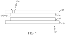
FIG. 1 is a cross-sectional schematic view of a gripping apparatus; -
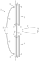
FIG. 2 is a cross-sectional schematic view of a system for gripping a flexible material; -
FIG. 3 is a flow chart of a method for gripping a flexible material; -
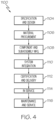
FIG. 4 is a flow chart is a block diagram of aircraft production and service methodology; and -
FIG. 5 is a schematic of the aircraft. - The following detailed description refers to the accompanying drawings, which illustrate specific examples described by the present disclosure. Other examples having different structures and operations do not depart from the scope of the present disclosure. Like reference numerals may refer to the same feature, element, or component in the different drawings.
- Illustrative, non-exhaustive examples, which may be, but are not necessarily, claimed, of the subject matter according to the present disclosure are provided below. Reference herein to "example" means that one or more feature, structure, element, component, characteristic, and/or operational step described in connection with the example is included in at least one embodiment and/or implementation of the subject matter according to the present disclosure. Thus, the phrases "an example," "another example," "an example," and similar language throughout the present disclosure may, but do not necessarily, refer to the same example. Further, the subject matter characterizing any one example may, but does not necessarily, include the subject matter characterizing any other example. Moreover, the subject matter characterizing any one example may be, but is not necessarily, combined with the subject matter characterizing any other example.
- In one or more examples, the gripping apparatus 110 (
FIG. 1 ), system 150 (FIG. 2 ), and method 200 (FIG. 3 ) may be used to facilitate manufacturing of composite parts, i.e., workpieces. In one example, composite parts, such as carbon fiber reinforcement polymer parts, are initially laid-up in multiple layers that together are referred to as a laminate or "prepreg." Individual fibers within each layer of the laminate are aligned parallel with each other, but different layers may exhibit different fiber orientations in order to increase the strength of the resulting composite part along different dimensions. The laminate may include a viscous resin that solidifies in order to harden the laminate into a composite part (e.g., for use in an aircraft). In an example, thegripping apparatus 110,system 150,method 200 may be used to facilitate manufacturing of composite parts comprised of thermoplastic resins. - Referring to
FIG. 1 , disclosed is agripping apparatus 110. Thegripping apparatus 110 includes animpermeable layer 112. Theimpermeable layer 112 defines avacuum port 164. In one example, theimpermeable layer 112 includes a polymeric material. In another example, theimpermeable layer 112 includes rubber. In one non-limiting example, theimpermeable layer 112 is Mosites™ rubber. - Still referring to
FIG. 1 , thegripping apparatus 110 includes a firstflow media layer 114 associated with the impermeable layer. In one example, the firstflow media layer 114 includes a biplanar mesh. In another example, the firstflow media layer 114 is in the form of a sheet, such as a sheet of biplanar mesh. - The
gripping apparatus 110 further includes a secondflow media layer 116 opposed from the firstflow media layer 114 to define a receivingspace 102 therebetween. The receivingspace 102 may be generally shaped and sized to receive aflexible material 130. In one example, the firstflow media layer 114 is adjacent to theimpermeable layer 112. In another example, the firstflow media layer 114 is connected to theimpermeable layer 112. - In one or more examples, the
gripping apparatus 110 further includes a secondimpermeable layer 118 associated with the secondflow media layer 116. The firstflow media layer 114 and the secondflow media layer 116 are positioned between theimpermeable layer 112 and the secondimpermeable layer 118. In one example, the secondflow media layer 116 is adjacent to the secondimpermeable layer 118. The secondimpermeable layer 118 may include a polymeric material. In another example, the secondimpermeable layer 118 may include rubber. In yet another example, the secondimpermeable layer 118 includes a metal. - In one or more examples, the
impermeable layer 112 is comprised of a first material and the secondimpermeable layer 118 is comprised of a second material. The first material and the second material may be compositionally substantially the same. Alternatively, the first material and the second material may be compositionally different. - Referring to
FIG. 2 , disclosed is asystem 150 for gripping a flexible material 130.Thesystem 150 includes agripping apparatus 110. Thegripping apparatus 110 includes animpermeable layer 112. In one or more examples, theimpermeable layer 112 of thegripping apparatus 110 comprises a polymeric material. In another example, theimpermeable layer 112 of thegripping apparatus 110 comprises rubber. - Still referring to
FIG. 2 , thegripping apparatus 110 of thesystem 150 includes a firstflow media layer 114 associated with theimpermeable layer 112 of thegripping apparatus 110. In one example, the firstflow media layer 114 of thegripping apparatus 110 is connected to theimpermeable layer 112. The firstflow media layer 114 of thegripping apparatus 110 may include a biplanar mesh. - Still referring to
FIG. 2 , thegripping apparatus 110 of thesystem 150 includes a secondflow media layer 116 opposed from the firstflow media layer 114 of thegripping apparatus 110 to define a receivingspace 102 therebetween. In one example, the secondflow media layer 116 of thegripping apparatus 110 includes a biplanar mesh. - The
gripping apparatus 110 of thesystem 150 may further include a secondimpermeable layer 118 associated with the secondflow media layer 116 of thegripping apparatus 110. The firstflow media layer 114 of thegripping apparatus 110 and the secondflow media layer 116 of thegripping apparatus 110 may be between theimpermeable layer 112 of thegripping apparatus 110 and the secondimpermeable layer 118 of thegripping apparatus 110. - Referring to
FIG. 2 , thesystem 150 includes a secondgripping apparatus 120. The secondgripping apparatus 120 includes animpermeable layer 122 and a firstflow media layer 124 associated with theimpermeable layer 122 of the secondgripping apparatus 120. - The second
gripping apparatus 120 of thesystem 150 further includes a secondflow media layer 126 opposed from the firstflow media layer 124 of the secondgripping apparatus 120 to define asecond receiving space 104 therebetween. The secondflow media layer 126 of the secondgripping apparatus 120 may include a biplanar mesh. - In one or more examples, the second
gripping apparatus 120 may further include a secondimpermeable layer 128 associated with the secondflow media layer 126 of the secondgripping apparatus 120. The firstflow media layer 124 of the secondgripping apparatus 120 and the secondflow media layer 126 of the secondgripping apparatus 120 may be between theimpermeable layer 122 of the secondgripping apparatus 120 and the secondimpermeable layer 128 of the secondgripping apparatus 120. - Still referring to
FIG. 2 , thesystem 150 further includes avacuum source 160 in fluid communication with thegripping apparatus 110 and the secondgripping apparatus 120. Thesystem 150 may further include afirst vacuum tube 162 fluidly coupling thevacuum source 160 with avacuum port 164 of thegripping apparatus 110. Further, thesystem 150 may include asecond vacuum tube 166 fluidly coupling thevacuum source 160 with asecond vacuum port 168 of the secondgripping apparatus 120. - In one or more examples, the
flexible material 130 includes a composite ply. In another example, theflexible material 130 includes a plurality of composite plies. In one example, thesystem 150 further includes arelease film 132 coupled to theflexible material 130. - Still referring to
FIG. 2 , thesystem 150 may further include atool 170 for engaging theflexible material 130. Thetool 170 may be a mandrel. In one example, thetool 170 is in the shape of an aerospace component. Thetool 170 may have prior a prior layer of theflexible material 130 on it, such as a ply of composite material. - Referring to
FIG. 3 , disclosed is amethod 200 for gripping aflexible material 130. Theflexible material 130 has afirst portion 134 andsecond portion 136. In one example, theflexible material 130 comprises a composite ply. In another example, theflexible material 130 includes a plurality of composite plies. In yet another example, theflexible material 130 is coupled to arelease film 132. - Still referring to
FIG. 3 , the method includes placing 210 agripping apparatus 110 into contact with thefirst portion 134 of theflexible material 130. Thegripping apparatus 110 includes animpermeable layer 112 and aflow media layer 114. Theimpermeable layer 112 defines avacuum port 164. In one example, theimpermeable layer 112 includes a polymeric material. In another example, theimpermeable layer 112 includes rubber. - In one example, the
gripping apparatus 110 includes a firstflow media layer 114 associated with the impermeable layer. In one example, the firstflow media layer 114 includes a biplanar mesh. In another example, the firstflow media layer 114 is in the form of a sheet, such as a sheet of biplanar mesh. - The
gripping apparatus 110 further includes a secondflow media layer 116 opposed from the firstflow media layer 114 to define a receivingspace 102 therebetween. The receivingspace 102 may be generally shaped and sized to receive aflexible material 130. In one example, the firstflow media layer 114 is adjacent to theimpermeable layer 112. In another example, the firstflow media layer 114 is connected to theimpermeable layer 112. - In one or more examples, the
gripping apparatus 110 further includes a secondimpermeable layer 118 associated with the secondflow media layer 116. The firstflow media layer 114 and the secondflow media layer 116 are positioned between theimpermeable layer 112 and the secondimpermeable layer 118. In one example, the secondflow media layer 116 is adjacent to the secondimpermeable layer 118. The secondimpermeable layer 118 may include a polymeric material. In another example, the secondimpermeable layer 118 may include rubber. In yet another example, the secondimpermeable layer 118 includes a metal. - In one or more examples, the
gripping apparatus 110impermeable layer 112 is comprised of a first material and thegripping apparatus 110 secondimpermeable layer 118 is comprised of a second material. The first material and the second material may be compositionally substantially the same. Alternatively, the first material and the second material may be compositionally different. - Still referring to
FIG. 3 , the method includes drawing 220 a vacuum between thegripping apparatus 110 and thefirst portion 134 of theflexible material 130 to engage thefirst portion 134 of theflexible material 130 with thegripping apparatus 110. In one example, the drawing 220 includes evacuation of air from thegripping apparatus 110 firstflow media layer 114 and thegripping apparatus 110 secondflow media layer 116. The drawing 220 locks thegripping apparatus 110 by evacuation of air, thus increasing friction among the layers of thegripping apparatus 110 and selectively controlling shear slippage. - The amount of vacuum drawn may vary based upon the material properties of the
flexible material 130. The drawing 220 results in a gripping force applied to theflexible material 130. The gripping force applied to theflexible material 130 is dependent on the amount of vacuum drawn. For example, the amount of vacuum drawn may be a function of theflexible material 130 shear slippage properties to permit the desired amount of shear slippage between theflexible material 130 and thegripping apparatus 110. - Still referring to
FIG. 3 , the method includes placing 230 a secondgripping apparatus 120 into contact with thesecond portion 136 of theflexible material 130, the secondgripping apparatus 120 comprising a secondgripping apparatus 120impermeable layer 122 and a secondgripping apparatus 120 firstflow media layer 124. - The second
gripping apparatus 120impermeable layer 122 defines asecond vacuum port 168. In one example, the secondgripping apparatus 120impermeable layer 122 includes a polymeric material. In another example, the secondgripping apparatus 120impermeable layer 122 includes rubber. In one non-limiting example, the secondgripping apparatus 120 impermeable layer includes Mosites™ rubber. - Referring to
FIG. 2 , the secondgripping apparatus 120 includes a secondgripping apparatus 120 firstflow media layer 124 associated with the impermeable layer. In one example, the secondgripping apparatus 120 firstflow media layer 124 includes a biplanar mesh. In another example, the secondgripping apparatus 120 firstflow media layer 124 is in the form of a sheet, such as a sheet of biplanar mesh. - The second
gripping apparatus 120 further includes a secondgripping apparatus 120 secondflow media layer 126 opposed from the secondgripping apparatus 120 firstflow media layer 124 to define a receivingspace 102 therebetween. The receivingspace 102 may be generally shaped and sized to receive aflexible material 130. In one example, the secondgripping apparatus 120 firstflow media layer 124 is adjacent to the secondgripping apparatus 120impermeable layer 122. In another example, the secondgripping apparatus 120 firstflow media layer 124 is connected to the secondgripping apparatus 120impermeable layer 122. - In one or more examples, the second
gripping apparatus 120 further includes a secondimpermeable layer 128 associated with the secondgripping apparatus 120 secondflow media layer 126. The secondgripping apparatus 120 firstflow media layer 124 and the secondgripping apparatus 120 secondflow media layer 126 are positioned between the secondgripping apparatus 120impermeable layer 122 and the secondgripping apparatus 120 secondimpermeable layer 128. In one example, the secondgripping apparatus 120 secondflow media layer 126 is adjacent to the secondgripping apparatus 120 secondimpermeable layer 128. The secondgripping apparatus 120 secondimpermeable layer 128 may include a polymeric material. In another example, the secondgripping apparatus 120 secondimpermeable layer 128 may include rubber. In yet another example, the secondgripping apparatus 120 secondimpermeable layer 128 includes a metal. - In one or more examples, the second
gripping apparatus 120impermeable layer 122 is comprised of a first material and the secondgripping apparatus 120 secondimpermeable layer 128 is comprised of a second material. The first material and the second material may be compositionally substantially the same. Alternatively, the first material and the second material may be compositionally different. - Still referring to
FIG. 3 , the method includes drawing 240 a vacuum between the secondgripping apparatus 120 and thesecond portion 136 of theflexible material 130 to engage thesecond portion 136 of theflexible material 130 with the secondgripping apparatus 120. In one example, the drawing 240 includes evacuation of air from the secondgripping apparatus 120 firstflow media layer 124 and the secondgripping apparatus 120 secondflow media layer 126. The drawing 240 locks the secondgripping apparatus 120 by evacuation of air, thus increasing friction among the layers of the secondgripping apparatus 120 and selectively controlling shear slippage. - The amount of vacuum drawn may vary based upon the material properties of the
flexible material 130. The drawing 240 results in a gripping force applied to theflexible material 130. The gripping force applied to theflexible material 130 is dependent on the amount of vacuum drawn. For example, the amount of vacuum drawn may be a function of theflexible material 130 shear slippage properties to permit the desired amount of shear slippage between theflexible material 130 and the secondgripping apparatus 120. - In one or more examples, the drawing 220 the vacuum between the
gripping apparatus 110 and thefirst portion 134 of theflexible material 130 comprises controlling 225 a vacuum flow rate to maintain engagement between thefirst portion 134 of theflexible material 130 and thegripping apparatus 110, while permitting shear slippage of thefirst portion 134 of theflexible material 130 relative to thegripping apparatus 110. For example, the gripping force between thegripping apparatus 110 and theflexible material 130 may be a function of the amount of vacuum drawn. - In one or more examples, the drawing 240 the vacuum between the second
gripping apparatus 120 and thesecond portion 136 of theflexible material 130 comprises controlling 245 a vacuum flow rate to maintain engagement between thesecond portion 136 of theflexible material 130 and the secondgripping apparatus 120, while permitting shear slippage of thesecond portion 136 of theflexible material 130 relative to the secondgripping apparatus 120. For example, the gripping force between the secondgripping apparatus 120 and theflexible material 130 may be a function of the amount of vacuum drawn. - Still referring to
FIG. 3 , themethod 200 further includes tensioning 250 theflexible material 130 while thefirst portion 134 of theflexible material 130 is engaged with thegripping apparatus 110 and thesecond portion 136 of theflexible material 130 is engaged with the secondgripping apparatus 120. In one example, thetensioning 250 comprises engaging 255 theflexible material 130 with atool 170. The engaging 255 may include draping theflexible material 130 over thetool 170. In another example, thetensioning 250 comprises moving 260 thegripping apparatus 110 relative to the secondgripping apparatus 120. In one example, the moving 260 includes moving 260 thegripping apparatus 110 away from the secondgripping apparatus 120. - Examples of the present disclosure may be described in the context of aircraft manufacturing and
service method 1100 as shown inFIG. 4 andaircraft 1102 as shown inFIG. 5 . During pre-production,service method 1100 may include specification and design (block 1104) ofaircraft 1102 and material procurement (Block 1106). During production, component and subassembly manufacturing (Block 1108) and system integration (Block 1110) ofaircraft 1102 may take place. Thereafter,aircraft 1102 may go through certification and delivery (Block 1112) to be placed in service (Block 1114). While in service,aircraft 1102 may be scheduled for routine maintenance and service (Block 1116). Routine maintenance and service may include modification, reconfiguration, refurbishment, etc. of one or more systems ofaircraft 1102. - Each of the processes of
service method 1100 may be performed or carried out by a system integrator, a third party, and/or an operator (e.g., a customer). For the purposes of this description, a system integrator may include, without limitation, any number of aircraft manufacturers and major-system subcontractors; a third party may include, without limitation, any number of vendors, subcontractors, and suppliers; and an operator may be an airline, leasing company, military entity, service organization, and so on. - As shown in
FIG. 5 ,aircraft 1102 produced byservice method 1100 may includeairframe 1118 with a plurality of high-level systems 1120 and interior 1122. Examples of high-level systems 1120 include one or more ofpropulsion system 1124,electrical system 1126,hydraulic system 1128, andenvironmental system 1130. Any number of other systems may be included. Although an aerospace example is shown, the principles disclosed herein may be applied to other industries, such as the automotive industry. Accordingly, in addition toaircraft 1102, the principles disclosed herein may apply to other vehicles, e.g., land vehicles, marine vehicles, space vehicles, etc. - Structure(s) and method(s) shown or described herein may be employed during any one or more of the stages of the manufacturing and
service method 1100. For example, components or subassemblies corresponding to component and subassembly manufacturing (block 1108) may be fabricated or manufactured in a manner similar to components or subassemblies produced whileaircraft 1102 is in service (Block 1114). Also, one or more examples of the structure(s), method(s), or combination thereof may be utilized during production stages production, component and subassembly manufacturing (Block 1108) and system integration (1110), for example, by substantially expediting assembly of or reducing the cost ofaircraft 1102. Similarly, one or more examples of the structure or method realizations, or a combination thereof, may be utilized, for example and without limitation, whileaircraft 1102 is in service (Block 1114) and/or during maintenance and service (Block 1116). - Further, the disclosure comprises embodiments according to the following clauses:
- Clause 1. A gripping apparatus (110) comprising:
- an impermeable layer (112) defining a vacuum port (164);
- a first flow media layer (114) associated with the impermeable layer (112); and
- a second flow media layer (116) opposed from the first flow media layer (114) to define a receiving space (102) therebetween.
- Clause 2. The gripping apparatus (110) of Clause 1, wherein the first flow media layer (114) is adjacent to the impermeable layer (112).
- Clause 3. The gripping apparatus (110) according to Clause 1 or 2, wherein the impermeable layer (112) comprises a polymeric material.
- Clause 4. The gripping apparatus (110) according to any one of Clauses 1 to 3, wherein the impermeable layer (112) comprises rubber.
- Clause 5. The gripping apparatus (110) according to any one of Clauses 1 to 4, wherein the first flow media layer (114) comprises a biplanar mesh.
- Clause 6. The gripping apparatus (110) according to any one of Clauses 1 to 5, further comprising a second impermeable layer (118) associated with the second flow media layer (116), wherein the first flow media layer (114) and the second flow media layer (116) are between the impermeable layer (112) and the second impermeable layer (118).
- Clause 7. The gripping apparatus of Clause 6, wherein the second flow media layer (116) is adjacent to the second impermeable layer (118).
- Clause 8. The gripping apparatus (110) according to Clause 6 or 7, wherein the second impermeable layer (118) comprises a polymeric material.
- Clause 9. The gripping apparatus (110) according to any one of Clauses 6 to 8, wherein the second impermeable layer (118) comprises rubber.
- Clause 10. The gripping apparatus (110) according to any one of Clauses 6 to 9, wherein the second impermeable layer (118) comprises metal.
- Clause 11. The gripping apparatus (110) according to any one of Clauses 6 to 10, wherein the impermeable layer (112) is comprised of a first material, wherein the second impermeable layer (118) is comprised of a second material, and wherein the first material and the second material are compositionally substantially the same.
- Clause 12. A system (150) for gripping a flexible material (130), the system (150) comprising:
- a gripping apparatus (110) comprising:
- an impermeable layer (112);
- a first flow media layer (114) associated with the impermeable layer (112) of the gripping apparatus (110); and
- a second flow media layer (116) opposed from the first flow media layer (114) of the gripping apparatus (110) to define a receiving space (102) therebetween;
- a second gripping apparatus (120) comprising:
- an impermeable layer (122);
- a first flow media layer (124) associated with the impermeable layer (122) of the second gripping apparatus (120); and
- a second flow media layer (126) opposed from the first flow media layer (124) of the second gripping apparatus (120) to define a second receiving space (104) therebetween; and
- a vacuum source (160) in fluid communication with the gripping apparatus (110) and the second gripping apparatus (120).
- a gripping apparatus (110) comprising:
- Clause 13. The system (150) of Clause 12, wherein the flexible material (130) comprises a composite ply.
- Clause 14. The system (150) according to Clause 12 or 13, wherein the impermeable layer (112) of the gripping apparatus (110) comprises rubber.
- Clause 15. The system (150) according to any one of Clauses 12 to 14, wherein the first flow media layer (114) of the gripping apparatus (110) comprises a biplanar mesh.
- Clause 16. The system (150) of Clause 15, wherein the second flow media layer (116) of the gripping apparatus (110) comprises a biplanar mesh.
- Clause 17. The system (150) according to any one of Clauses 12 to 16, wherein the gripping apparatus (110) further comprises a second impermeable layer (118) associated with the second flow media layer (116) of the gripping apparatus (110), and wherein the first flow media layer (114) of the gripping apparatus (110) and the second flow media layer (116) of the gripping apparatus (110) are between the impermeable layer (112) of the gripping apparatus (110) and the second impermeable layer (118) of the gripping apparatus (110).
- Clause 18. The system (150) according to any one of Clauses 12 to 17, wherein the second gripping apparatus (120) further comprises a second impermeable layer (120) associated with the second flow media layer (126) of the second gripping apparatus (120), and wherein the first flow media layer (124) of the second gripping apparatus (120) and the second flow media layer (126) of the second gripping apparatus (120) are between the impermeable layer (122) of the second gripping apparatus (120) and the second impermeable layer (128) of the second gripping apparatus (120).
- Clause 19. The system (150) according to any one of Clauses 12 to 18, further comprising a release film (132) coupled to the flexible material (130).
- Clause 20. The system (150) according to any one of Clauses 12 to 19, further comprising a first vacuum tube (162) fluidly coupling the vacuum source (160) with a vacuum port (164) of the gripping apparatus (110).
- Clause 21. The system (150) according to any one of Clauses 12 to 20, further comprising a second vacuum tube (166) fluidly coupling the vacuum source (160) with a second vacuum port (168) of the second gripping apparatus (120).
- Clause 22. The system according to any one of Clauses 12 to 21, further comprising a tool (17) for engaging the flexible material (130).
- Clause 23. A method (200) for gripping a flexible material (130), the flexible material (130) comprising a first portion (134) and second portion (136), the method comprising:
- placing (210) a gripping apparatus (110) into contact with the first portion (134) of the flexible material (130), the gripping apparatus (110) comprising an impermeable layer (112) and a flow media layer (114);
- drawing (220) a vacuum between the gripping apparatus (110) and the first portion (134) of the flexible material (130) to engage the first portion (134) of the flexible material (130) with the gripping apparatus (110);
- placing (230) a second gripping apparatus (120) into contact with the second portion (136) of the flexible material (130), the second gripping apparatus (120) comprising an impermeable layer (122) and a flow media layer (124); and
- drawing (240) a vacuum between the second gripping apparatus (120) and the second portion (136) of the flexible material (130) to engage the second portion (136) of the flexible material (130) with the second gripping apparatus (120).
- Clause 24. The method (200) of Clause 23, wherein the flexible material (130) comprises a composite ply.
- Clause 25. The method (200) according to Clause 23 or 24, wherein the impermeable layer (112) of the gripping apparatus (110) comprises rubber.
- Clause 26. The method (200) according to any one of Clauses 23 to 25, wherein the flow media layer (114) of the gripping apparatus (110) comprises a biplanar mesh.
- Clause 27. The method (200) according to any one of Clauses 23 to 26, wherein the impermeable layer (122) of the second gripping apparatus (120) comprises rubber.
- Clause 28. The method (200) according to any one of Clauses 23 to 27, wherein the flow media layer (124) of the second gripping apparatus (120) comprises a biplanar mesh.
- Clause 29. The method (200) according to any one of Clauses 23 to 28, wherein the gripping apparatus (110) further comprises a second impermeable layer (118) and a second flow media layer (116), and wherein the flow media layer (114) of the gripping apparatus (110) and the second flow media layer (116) of the gripping apparatus (110) are between the impermeable layer (112) of the gripping apparatus (110) and the second impermeable layer (118) of the gripping apparatus (110).
- Clause 30. The method (200) according to any one of Clauses 23 to 29, wherein the second gripping apparatus (120) further comprises a second impermeable layer (120) and a second flow media layer (126), and wherein the flow media layer (124) of the second gripping apparatus (120) and the second flow media layer (126) of the second gripping apparatus (120) are between the impermeable layer (122) of the second gripping apparatus (120) and the second impermeable layer (128) of the second gripping apparatus (120).
- Clause 31. The method (200) according to any one of Clauses 23 to 30, wherein the drawing (220) the vacuum between the gripping apparatus (110) and the first portion (134) of the flexible material (130) comprises controlling (225) a vacuum flow rate to maintain engagement between the first portion (134) of the flexible material (130) and the gripping apparatus (110), while permitting shear slippage of the first portion (134) of the flexible material (130) relative to the gripping apparatus (110).
- Clause 32. The method (200) according to any one of Clauses 23 to 31, wherein the drawing (240) the vacuum between the second gripping apparatus (120) and the second portion (136) of the flexible material (130) comprises controlling (245) a vacuum flow rate to maintain engagement between the second portion (136) of the flexible material (130) and the second gripping apparatus (120), while permitting shear slippage of the second portion (136) of the flexible material (130) relative to the second gripping apparatus (120).
- Clause 33. The method (200) according to any one of Clauses 23 to 32, further comprising tensioning (250) the flexible material (130) while the first portion (134) of the flexible material (130) is engaged with the gripping apparatus (110) and the second portion (136) of the flexible material (130) is engaged with the second gripping apparatus (120).
- Clause 34. The method according to Clause 33, wherein the tensioning (250) comprises engaging (255) the flexible material (130) with a tool (170).
- Clause 35. The method according to Clauses 33 or 34, wherein the tensioning (250) comprises moving (260) the gripping apparatus (110) relative to the second gripping apparatus (120).
- Different examples of the structure(s) and method(s) disclosed herein include a variety of components, features, and functionalities. It should be understood that the various examples of the structure(s) and method(s) disclosed herein may include any of the components, features, and functionalities of any of the other examples of the structure(s) and method(s) disclosed herein in any combination, and all of such possibilities are intended to be within the scope of the present disclosure.
- Many modifications of examples set forth herein will come to mind to one skilled in the art to which the present disclosure pertains having the benefit of the teachings presented in the foregoing descriptions and the associated drawings.
- Therefore, it is to be understood that the present disclosure is not to be limited to the specific examples illustrated and that modifications and other examples are intended to be included within the scope of the appended claims. Moreover, although the foregoing description and the associated drawings describe examples of the present disclosure in the context of certain illustrative combinations of elements and/or functions, it should be appreciated that different combinations of elements and/or functions may be provided by alternative implementations without departing from the scope of the appended claims. Accordingly, parenthetical reference numerals in the appended claims are presented for illustrative purposes only and are not intended to limit the scope of the claimed subject matter to the specific examples provided in the present disclosure.
Claims (15)
- A gripping apparatus comprising:an impermeable layer defining a vacuum port;a first flow media layer associated with the impermeable layer; anda second flow media layer opposed from the first flow media layer to define a receiving space therebetween.
- The gripping apparatus of Claim 1, wherein the first flow media layer is adjacent to the impermeable layer.
- The gripping apparatus of Claim 1or 2, wherein the first flow media layer comprises a biplanar mesh.
- The gripping apparatus of any of Claims 1 to 3, further comprising a second impermeable layer associated with the second flow media layer, wherein the first flow media layer and the second flow media layer are between the impermeable layer and the second impermeable layer.
- The gripping apparatus of Claim 4, wherein the second flow media layer is adjacent to the second impermeable layer.
- A system for gripping a flexible material, the system comprising:a gripping apparatus comprising:an impermeable layer;a first flow media layer associated with the impermeable layer of the gripping apparatus; anda second flow media layer opposed from the first flow media layer of the gripping apparatus to define a receiving space therebetween;a second gripping apparatus comprising:an impermeable layer;a first flow media layer associated with the impermeable layer of the second gripping apparatus; anda second flow media layer opposed from the first flow media layer of the second gripping apparatus to define a second receiving space therebetween; anda vacuum source in fluid communication with the gripping apparatus and the second gripping apparatus.
- The system of Claim 6, wherein the gripping apparatus further comprises a second impermeable layer associated with the second flow media layer of the gripping apparatus, and wherein the first flow media layer of the gripping apparatus and the second flow media layer of the gripping apparatus are between the impermeable layer of the gripping apparatus and the second impermeable layer of the gripping apparatus.
- The system of Claim 6 or 7, wherein the second gripping apparatus further comprises a second impermeable layer associated with the second flow media layer of the second gripping apparatus, and wherein the first flow media layer of the second gripping apparatus and the second flow media layer of the second gripping apparatus are between the impermeable layer of the second gripping apparatus and the second impermeable layer of the second gripping apparatus.
- A method for gripping a flexible material, the flexible material comprising a first portion and second portion, the method comprising:placing a gripping apparatus into contact with the first portion of the flexible material, the gripping apparatus comprising an impermeable layer and a flow media layer;drawing a vacuum between the gripping apparatus and the first portion of the flexible material to engage the first portion of the flexible material with the gripping apparatus;placing a second gripping apparatus into contact with the second portion of the flexible material, the second gripping apparatus comprising an impermeable layer and a flow media layer; anddrawing a vacuum between the second gripping apparatus and the second portion of the flexible material to engage the second portion of the flexible material with the second gripping apparatus.
- The method of Claim 9, wherein the second gripping apparatus further comprises a second impermeable layer and a second flow media layer, and wherein the flow media layer of the second gripping apparatus and the second flow media layer of the second gripping apparatus are between the impermeable layer of the second gripping apparatus and the second impermeable layer of the second gripping apparatus.
- The method of Claim 9 or 10, wherein the drawing the vacuum between the gripping apparatus and the first portion of the flexible material comprises controlling a vacuum flow rate to maintain engagement between the first portion of the flexible material and the gripping apparatus, while permitting shear slippage of the first portion of the flexible material relative to the gripping apparatus.
- The method of any of Claims 9 to 11, wherein the drawing the vacuum between the second gripping apparatus and the second portion of the flexible material comprises controlling a vacuum flow rate to maintain engagement between the second portion of the flexible material and the second gripping apparatus, while permitting shear slippage of the second portion of the flexible material relative to the second gripping apparatus.
- The method of any of Claims 9 to 12, further comprising tensioning the flexible material while the first portion of the flexible material is engaged with the gripping apparatus and the second portion of the flexible material is engaged with the second gripping apparatus.
- The method of Claim 13, wherein the tensioning comprises engaging the flexible material with a tool.
- The method according to Claim 13 or 14, wherein the tensioning comprises moving the gripping apparatus relative to the second gripping apparatus.
Applications Claiming Priority (1)
| Application Number | Priority Date | Filing Date | Title |
|---|---|---|---|
| US17/644,376 US12558799B2 (en) | 2021-12-15 | 2021-12-15 | Gripping apparatus and associated systems and methods for gripping flexible materials |
Publications (2)
| Publication Number | Publication Date |
|---|---|
| EP4197719A1 true EP4197719A1 (en) | 2023-06-21 |
| EP4197719B1 EP4197719B1 (en) | 2025-12-03 |
Family
ID=84331855
Family Applications (1)
| Application Number | Title | Priority Date | Filing Date |
|---|---|---|---|
| EP22200376.6A Active EP4197719B1 (en) | 2021-12-15 | 2022-10-07 | Gripping apparatus and associated systems and methods for gripping flexible materials |
Country Status (6)
| Country | Link |
|---|---|
| US (1) | US12558799B2 (en) |
| EP (1) | EP4197719B1 (en) |
| JP (1) | JP2023088843A (en) |
| CN (1) | CN116262574A (en) |
| AU (1) | AU2022252822A1 (en) |
| ES (1) | ES3064159T3 (en) |
Citations (2)
| Publication number | Priority date | Publication date | Assignee | Title |
|---|---|---|---|---|
| US20190344447A1 (en) * | 2018-05-09 | 2019-11-14 | Intelligrated Headquarters, Llc | Method and system for manipulating items |
| US20210107169A1 (en) * | 2019-10-10 | 2021-04-15 | The Boeing Company | Placement and compaction of objects via vacuum |
Family Cites Families (15)
| Publication number | Priority date | Publication date | Assignee | Title |
|---|---|---|---|---|
| DK2146821T3 (en) * | 2007-04-26 | 2012-07-02 | Adept Technology Inc | VACUUM GRIP UNIT |
| TWI388418B (en) * | 2008-10-09 | 2013-03-11 | 日立產機系統股份有限公司 | Precision imprinting device and its embossing load control method |
| US8696043B2 (en) * | 2011-11-18 | 2014-04-15 | Nike, Inc. | Hybrid pickup tool |
| US10005256B2 (en) | 2012-06-14 | 2018-06-26 | The Boeing Company | Selectively weakened stretched films |
| US9908718B2 (en) * | 2012-10-19 | 2018-03-06 | Dow Global Technologies Llc | Device, system, and method for lifting and moving formable and/or collapsible parts |
| US10166704B2 (en) * | 2013-02-08 | 2019-01-01 | Global Ip Holdings, Llc | Method of making a laminated trim component at a pair of spaced first and second molding stations |
| DE102014110464B4 (en) * | 2014-07-24 | 2021-11-11 | Deutsches Zentrum für Luft- und Raumfahrt e.V. | Gripping device |
| US10099385B2 (en) * | 2017-02-06 | 2018-10-16 | The Boeing Company | End effectors carrying plies of material for shaping by a mandrel |
| US11097524B2 (en) * | 2017-05-26 | 2021-08-24 | The Boeing Company | Flexible vacuum securement of objects to complex surfaces |
| US10160169B1 (en) * | 2017-06-26 | 2018-12-25 | General Electric Company | Systems and methods of forming a composite layup structure |
| US10532828B2 (en) * | 2017-06-30 | 2020-01-14 | The Boeing Company | Apparatus, systems, and methods for automated part installation |
| KR20200025079A (en) * | 2018-08-29 | 2020-03-10 | (주)포인트엔지니어링 | Transfer head |
| US11104468B1 (en) * | 2018-09-18 | 2021-08-31 | Amazon Technologies, Inc. | End effector and system for label application |
| US11318689B2 (en) * | 2018-12-21 | 2022-05-03 | The Boeing Company | Ply transporting and compacting apparatus and method therefor |
| US11618248B2 (en) * | 2020-07-13 | 2023-04-04 | Southwest Research Institute | End of arm tool (EOAT) for layup of pre-impregnated composite laminates and robotic arm control system and method |
-
2021
- 2021-12-15 US US17/644,376 patent/US12558799B2/en active Active
-
2022
- 2022-10-07 ES ES22200376T patent/ES3064159T3/en active Active
- 2022-10-07 EP EP22200376.6A patent/EP4197719B1/en active Active
- 2022-10-11 JP JP2022163174A patent/JP2023088843A/en active Pending
- 2022-10-14 AU AU2022252822A patent/AU2022252822A1/en active Pending
- 2022-12-01 CN CN202211531950.8A patent/CN116262574A/en active Pending
Patent Citations (2)
| Publication number | Priority date | Publication date | Assignee | Title |
|---|---|---|---|---|
| US20190344447A1 (en) * | 2018-05-09 | 2019-11-14 | Intelligrated Headquarters, Llc | Method and system for manipulating items |
| US20210107169A1 (en) * | 2019-10-10 | 2021-04-15 | The Boeing Company | Placement and compaction of objects via vacuum |
Also Published As
| Publication number | Publication date |
|---|---|
| AU2022252822A1 (en) | 2023-06-29 |
| ES3064159T3 (en) | 2026-04-22 |
| US20230182321A1 (en) | 2023-06-15 |
| EP4197719B1 (en) | 2025-12-03 |
| US12558799B2 (en) | 2026-02-24 |
| JP2023088843A (en) | 2023-06-27 |
| CN116262574A (en) | 2023-06-16 |
Similar Documents
| Publication | Publication Date | Title |
|---|---|---|
| US8298473B2 (en) | Method of making a cure tool with integrated edge breather | |
| US8551380B2 (en) | Method of laying up prepreg plies on contoured tools using a deformable carrier film | |
| CA2769629C (en) | Multi-functional aircraft structures | |
| US9586344B2 (en) | Method and system of forming a releasable support and method of pre-cure removal of a composite laminate | |
| US9272495B1 (en) | Compaction system for composite stringers | |
| US11155069B2 (en) | Method and system of forming a composite laminate | |
| US10647406B2 (en) | Closed-angle composite airfoil spar and method of fabricating the same | |
| EP3015258A1 (en) | Method and apparatus for vacuum forming composite laminates | |
| CN112721232A (en) | Placing and compacting objects via vacuum | |
| EP3815888B1 (en) | Vacuum bag-less composite repair systems and repairs | |
| US20170182738A1 (en) | Composite Filler | |
| EP3613567B1 (en) | Flexible mandrel for forming composite structures | |
| US9545758B2 (en) | Two piece mandrel manufacturing system | |
| EP4194172A1 (en) | Pliable structures and associated methods and systems for replicating a contour of a surface | |
| US12558799B2 (en) | Gripping apparatus and associated systems and methods for gripping flexible materials | |
| US9308704B2 (en) | Elastomeric bladder system | |
| US11993034B2 (en) | Integrated caul with elastomeric seals | |
| US9511520B1 (en) | Method, apparatus and device for preventing vacuum bag wrinkling | |
| US9623641B1 (en) | Method and apparatus for reinforcing a bladder | |
| US20260091572A1 (en) | Reinforcement film for a sandwich core and method of making a reinforced sandwich core | |
| US20230311431A1 (en) | Methods for configuring a shape of a tool and associated systems and methods for manufacturing a composite structure | |
| US10913221B2 (en) | Shaping a radius filler against a mandrel | |
| NL2021422B1 (en) | Ply location templates for double diaphragm vacuum bagging systems | |
| US10875264B2 (en) | Ply location templates for double diaphragm vacuum bagging systems | |
| US20190389155A1 (en) | Ply location templates for double diaphragm vacuum bagging systems |
Legal Events
| Date | Code | Title | Description |
|---|---|---|---|
| PUAI | Public reference made under article 153(3) epc to a published international application that has entered the european phase |
Free format text: ORIGINAL CODE: 0009012 |
|
| STAA | Information on the status of an ep patent application or granted ep patent |
Free format text: STATUS: THE APPLICATION HAS BEEN PUBLISHED |
|
| AK | Designated contracting states |
Kind code of ref document: A1 Designated state(s): AL AT BE BG CH CY CZ DE DK EE ES FI FR GB GR HR HU IE IS IT LI LT LU LV MC ME MK MT NL NO PL PT RO RS SE SI SK SM TR |
|
| STAA | Information on the status of an ep patent application or granted ep patent |
Free format text: STATUS: REQUEST FOR EXAMINATION WAS MADE |
|
| 17P | Request for examination filed |
Effective date: 20231215 |
|
| RBV | Designated contracting states (corrected) |
Designated state(s): AL AT BE BG CH CY CZ DE DK EE ES FI FR GB GR HR HU IE IS IT LI LT LU LV MC ME MK MT NL NO PL PT RO RS SE SI SK SM TR |
|
| GRAP | Despatch of communication of intention to grant a patent |
Free format text: ORIGINAL CODE: EPIDOSNIGR1 |
|
| STAA | Information on the status of an ep patent application or granted ep patent |
Free format text: STATUS: GRANT OF PATENT IS INTENDED |
|
| RIC1 | Information provided on ipc code assigned before grant |
Ipc: B29C 70/38 20060101ALN20250122BHEP Ipc: B29C 37/00 20060101ALN20250122BHEP Ipc: B29C 31/08 20060101ALI20250122BHEP Ipc: B65H 5/14 20060101ALI20250122BHEP Ipc: B25J 15/06 20060101AFI20250122BHEP |
|
| INTG | Intention to grant announced |
Effective date: 20250130 |
|
| GRAJ | Information related to disapproval of communication of intention to grant by the applicant or resumption of examination proceedings by the epo deleted |
Free format text: ORIGINAL CODE: EPIDOSDIGR1 |
|
| STAA | Information on the status of an ep patent application or granted ep patent |
Free format text: STATUS: REQUEST FOR EXAMINATION WAS MADE |
|
| GRAP | Despatch of communication of intention to grant a patent |
Free format text: ORIGINAL CODE: EPIDOSNIGR1 |
|
| STAA | Information on the status of an ep patent application or granted ep patent |
Free format text: STATUS: GRANT OF PATENT IS INTENDED |
|
| P01 | Opt-out of the competence of the unified patent court (upc) registered |
Free format text: CASE NUMBER: APP_19756/2025 Effective date: 20250424 |
|
| INTC | Intention to grant announced (deleted) | ||
| RIC1 | Information provided on ipc code assigned before grant |
Ipc: B29C 70/38 20060101ALN20250506BHEP Ipc: B29C 37/00 20060101ALN20250506BHEP Ipc: B29C 31/08 20060101ALI20250506BHEP Ipc: B65H 5/14 20060101ALI20250506BHEP Ipc: B25J 15/06 20060101AFI20250506BHEP |
|
| INTG | Intention to grant announced |
Effective date: 20250514 |
|
| GRAS | Grant fee paid |
Free format text: ORIGINAL CODE: EPIDOSNIGR3 |
|
| GRAA | (expected) grant |
Free format text: ORIGINAL CODE: 0009210 |
|
| STAA | Information on the status of an ep patent application or granted ep patent |
Free format text: STATUS: THE PATENT HAS BEEN GRANTED |
|
| AK | Designated contracting states |
Kind code of ref document: B1 Designated state(s): AL AT BE BG CH CY CZ DE DK EE ES FI FR GB GR HR HU IE IS IT LI LT LU LV MC ME MK MT NL NO PL PT RO RS SE SI SK SM TR |
|
| REG | Reference to a national code |
Ref country code: CH Ref legal event code: F10 Free format text: ST27 STATUS EVENT CODE: U-0-0-F10-F00 (AS PROVIDED BY THE NATIONAL OFFICE) Effective date: 20251203 Ref country code: GB Ref legal event code: FG4D |
|
| REG | Reference to a national code |
Ref country code: DE Ref legal event code: R096 Ref document number: 602022026019 Country of ref document: DE |
|
| REG | Reference to a national code |
Ref country code: SE Ref legal event code: TRGR |
|
| REG | Reference to a national code |
Ref country code: IE Ref legal event code: FG4D |
|
| REG | Reference to a national code |
Ref country code: NL Ref legal event code: MP Effective date: 20251203 |
|
| REG | Reference to a national code |
Ref country code: LT Ref legal event code: MG9D |
|
| PG25 | Lapsed in a contracting state [announced via postgrant information from national office to epo] |
Ref country code: NO Free format text: LAPSE BECAUSE OF FAILURE TO SUBMIT A TRANSLATION OF THE DESCRIPTION OR TO PAY THE FEE WITHIN THE PRESCRIBED TIME-LIMIT Effective date: 20260303 |
|
| PG25 | Lapsed in a contracting state [announced via postgrant information from national office to epo] |
Ref country code: HR Free format text: LAPSE BECAUSE OF FAILURE TO SUBMIT A TRANSLATION OF THE DESCRIPTION OR TO PAY THE FEE WITHIN THE PRESCRIBED TIME-LIMIT Effective date: 20251203 Ref country code: FI Free format text: LAPSE BECAUSE OF FAILURE TO SUBMIT A TRANSLATION OF THE DESCRIPTION OR TO PAY THE FEE WITHIN THE PRESCRIBED TIME-LIMIT Effective date: 20251203 |
|
| PG25 | Lapsed in a contracting state [announced via postgrant information from national office to epo] |
Ref country code: RS Free format text: LAPSE BECAUSE OF FAILURE TO SUBMIT A TRANSLATION OF THE DESCRIPTION OR TO PAY THE FEE WITHIN THE PRESCRIBED TIME-LIMIT Effective date: 20260303 |
|
| REG | Reference to a national code |
Ref country code: ES Ref legal event code: FG2A Ref document number: 3064159 Country of ref document: ES Kind code of ref document: T3 Effective date: 20260422 |
|
| PG25 | Lapsed in a contracting state [announced via postgrant information from national office to epo] |
Ref country code: PL Free format text: LAPSE BECAUSE OF FAILURE TO SUBMIT A TRANSLATION OF THE DESCRIPTION OR TO PAY THE FEE WITHIN THE PRESCRIBED TIME-LIMIT Effective date: 20251203 |
|
| PG25 | Lapsed in a contracting state [announced via postgrant information from national office to epo] |
Ref country code: LV Free format text: LAPSE BECAUSE OF FAILURE TO SUBMIT A TRANSLATION OF THE DESCRIPTION OR TO PAY THE FEE WITHIN THE PRESCRIBED TIME-LIMIT Effective date: 20251203 |
|
| PG25 | Lapsed in a contracting state [announced via postgrant information from national office to epo] |
Ref country code: BG Free format text: LAPSE BECAUSE OF FAILURE TO SUBMIT A TRANSLATION OF THE DESCRIPTION OR TO PAY THE FEE WITHIN THE PRESCRIBED TIME-LIMIT Effective date: 20251203 |
|
| REG | Reference to a national code |
Ref country code: AT Ref legal event code: MK05 Ref document number: 1863172 Country of ref document: AT Kind code of ref document: T Effective date: 20251203 |
|
| PG25 | Lapsed in a contracting state [announced via postgrant information from national office to epo] |
Ref country code: NL Free format text: LAPSE BECAUSE OF FAILURE TO SUBMIT A TRANSLATION OF THE DESCRIPTION OR TO PAY THE FEE WITHIN THE PRESCRIBED TIME-LIMIT Effective date: 20251203 |
|
| PG25 | Lapsed in a contracting state [announced via postgrant information from national office to epo] |
Ref country code: LT Free format text: LAPSE BECAUSE OF FAILURE TO SUBMIT A TRANSLATION OF THE DESCRIPTION OR TO PAY THE FEE WITHIN THE PRESCRIBED TIME-LIMIT Effective date: 20251203 |
|
| PG25 | Lapsed in a contracting state [announced via postgrant information from national office to epo] |
Ref country code: SM Free format text: LAPSE BECAUSE OF FAILURE TO SUBMIT A TRANSLATION OF THE DESCRIPTION OR TO PAY THE FEE WITHIN THE PRESCRIBED TIME-LIMIT Effective date: 20251203 |
|
| PG25 | Lapsed in a contracting state [announced via postgrant information from national office to epo] |
Ref country code: AT Free format text: LAPSE BECAUSE OF FAILURE TO SUBMIT A TRANSLATION OF THE DESCRIPTION OR TO PAY THE FEE WITHIN THE PRESCRIBED TIME-LIMIT Effective date: 20251203 |
|
| PG25 | Lapsed in a contracting state [announced via postgrant information from national office to epo] |
Ref country code: EE Free format text: LAPSE BECAUSE OF FAILURE TO SUBMIT A TRANSLATION OF THE DESCRIPTION OR TO PAY THE FEE WITHIN THE PRESCRIBED TIME-LIMIT Effective date: 20251203 |
|
| PG25 | Lapsed in a contracting state [announced via postgrant information from national office to epo] |
Ref country code: PT Free format text: LAPSE BECAUSE OF FAILURE TO SUBMIT A TRANSLATION OF THE DESCRIPTION OR TO PAY THE FEE WITHIN THE PRESCRIBED TIME-LIMIT Effective date: 20260406 Ref country code: IS Free format text: LAPSE BECAUSE OF FAILURE TO SUBMIT A TRANSLATION OF THE DESCRIPTION OR TO PAY THE FEE WITHIN THE PRESCRIBED TIME-LIMIT Effective date: 20260403 |
|
| PG25 | Lapsed in a contracting state [announced via postgrant information from national office to epo] |
Ref country code: CZ Free format text: LAPSE BECAUSE OF FAILURE TO SUBMIT A TRANSLATION OF THE DESCRIPTION OR TO PAY THE FEE WITHIN THE PRESCRIBED TIME-LIMIT Effective date: 20251203 |
|
| PG25 | Lapsed in a contracting state [announced via postgrant information from national office to epo] |
Ref country code: SK Free format text: LAPSE BECAUSE OF FAILURE TO SUBMIT A TRANSLATION OF THE DESCRIPTION OR TO PAY THE FEE WITHIN THE PRESCRIBED TIME-LIMIT Effective date: 20251203 |