EP4197693A1 - Operating device with differentiated rotational speed outputs and machine tool including such operating device - Google Patents
Operating device with differentiated rotational speed outputs and machine tool including such operating device Download PDFInfo
- Publication number
- EP4197693A1 EP4197693A1 EP22212477.8A EP22212477A EP4197693A1 EP 4197693 A1 EP4197693 A1 EP 4197693A1 EP 22212477 A EP22212477 A EP 22212477A EP 4197693 A1 EP4197693 A1 EP 4197693A1
- Authority
- EP
- European Patent Office
- Prior art keywords
- rotation axis
- toothed wheel
- shaft
- outlet shaft
- outlet
- Prior art date
- Legal status (The legal status is an assumption and is not a legal conclusion. Google has not performed a legal analysis and makes no representation as to the accuracy of the status listed.)
- Pending
Links
- 230000033001 locomotion Effects 0.000 claims abstract description 23
- 238000003754 machining Methods 0.000 claims abstract description 10
- 230000005540 biological transmission Effects 0.000 description 3
- 239000000463 material Substances 0.000 description 3
- 239000011521 glass Substances 0.000 description 2
- 239000002184 metal Substances 0.000 description 2
- 239000004033 plastic Substances 0.000 description 2
- 239000002023 wood Substances 0.000 description 2
- 238000000034 method Methods 0.000 description 1
- 238000012986 modification Methods 0.000 description 1
- 230000004048 modification Effects 0.000 description 1
- 230000009466 transformation Effects 0.000 description 1
- 230000003245 working effect Effects 0.000 description 1
Images


Classifications
-
- B—PERFORMING OPERATIONS; TRANSPORTING
- B23—MACHINE TOOLS; METAL-WORKING NOT OTHERWISE PROVIDED FOR
- B23Q—DETAILS, COMPONENTS, OR ACCESSORIES FOR MACHINE TOOLS, e.g. ARRANGEMENTS FOR COPYING OR CONTROLLING; MACHINE TOOLS IN GENERAL CHARACTERISED BY THE CONSTRUCTION OF PARTICULAR DETAILS OR COMPONENTS; COMBINATIONS OR ASSOCIATIONS OF METAL-WORKING MACHINES, NOT DIRECTED TO A PARTICULAR RESULT
- B23Q5/00—Driving or feeding mechanisms; Control arrangements therefor
- B23Q5/02—Driving main working members
- B23Q5/04—Driving main working members rotary shafts, e.g. working-spindles
- B23Q5/043—Accessories for spindle drives
- B23Q5/045—Angle drives
-
- B—PERFORMING OPERATIONS; TRANSPORTING
- B23—MACHINE TOOLS; METAL-WORKING NOT OTHERWISE PROVIDED FOR
- B23Q—DETAILS, COMPONENTS, OR ACCESSORIES FOR MACHINE TOOLS, e.g. ARRANGEMENTS FOR COPYING OR CONTROLLING; MACHINE TOOLS IN GENERAL CHARACTERISED BY THE CONSTRUCTION OF PARTICULAR DETAILS OR COMPONENTS; COMBINATIONS OR ASSOCIATIONS OF METAL-WORKING MACHINES, NOT DIRECTED TO A PARTICULAR RESULT
- B23Q5/00—Driving or feeding mechanisms; Control arrangements therefor
- B23Q5/02—Driving main working members
- B23Q5/04—Driving main working members rotary shafts, e.g. working-spindles
- B23Q5/043—Accessories for spindle drives
- B23Q5/048—Speed-changing devices
-
- B—PERFORMING OPERATIONS; TRANSPORTING
- B23—MACHINE TOOLS; METAL-WORKING NOT OTHERWISE PROVIDED FOR
- B23Q—DETAILS, COMPONENTS, OR ACCESSORIES FOR MACHINE TOOLS, e.g. ARRANGEMENTS FOR COPYING OR CONTROLLING; MACHINE TOOLS IN GENERAL CHARACTERISED BY THE CONSTRUCTION OF PARTICULAR DETAILS OR COMPONENTS; COMBINATIONS OR ASSOCIATIONS OF METAL-WORKING MACHINES, NOT DIRECTED TO A PARTICULAR RESULT
- B23Q2220/00—Machine tool components
- B23Q2220/002—Tool turrets
Definitions
- the present invention relates to an operating device with differentiated rotational speed outputs and machine tool including such operating device.
- a pass-through machine tool i.e. a machine tool in which the workpiece to be machined is advanced along a given advancement direction during the execution of the machining operations, but it is clear that the same should not be considered limited to this particular type of machine tool, as it can also be extended to machine tools of other types.
- the invention proposed here belongs to the field of operating devices, commonly called “operating aggregates” or “operating heads” in the specific jargon of the reference sector, intended to be used in machine tools for working pieces in wood, glass, plastic, metal or other materials, and to be coupled simultaneously to several machining tools.
- these devices are equipped with a rotating input shaft, connected to the rotating shaft of an electro-spindle unit of the machine tool, and with a plurality of rotating output shafts, each connectable to a tool and connected to the input shaft so that the latter can simultaneously transmit a rotary motion to said output shafts and therefore to the relative tools mounted thereon.
- an object of the present invention to provide an operating device with outlets at different rotation speeds, which allows for performing different types of machining without having to replace the tools mounted on these outlets.
- Another object of the invention is to provide an operating device with outputs at different rotation speeds, which allows having an adequate cutting speed for each type of tool or for each type of machining to be carried out on the workpiece.
- Another object of the invention is to provide an operating device with outputs at differentiated rotation speeds which is multipurpose.
- a further object of the present invention is to provide an operating device with outputs at differentiated rotation speeds, which has a high degree of flexibility of use.
- Another object of the invention is to provide an operating device with outputs at differentiated rotation speeds, which has a non-complex structure.
- an operative device for a machine tool which is suitable for machining at least one piece and provided with an electrospindle unit
- said operative device comprising: an inlet shaft which is rotatable about a first rotation axis and connectable, in use, with said electrospindle unit such that said inlet shaft is rotated, in use, by said electrospindle unit about said first rotation axis; a first toothed wheel being conical and a second toothed wheel being conical, which are coaxially coupled to said inlet shaft; a first outlet shaft which is rotatable about a second rotation axis being substantially orthogonal to said first rotation axis of said inlet shaft, wherein said first outlet shaft is connectable, in use, with a first tool; a third toothed wheel, conical, which is coaxially coupled to said first outlet shaft and engaged with said first toothed wheel such that, in use, said first toothed wheel rotating about said first rotation axis of said inlet
- said second outlet shaft may rotate faster than said first outlet shaft, based on said first gear ratio and second gear ratio.
- said third rotation axis of said second outlet shaft may be substantially at 90 degrees with respect to said second rotation axis of said first outlet shaft.
- said first outlet shaft may comprise connection means to allow, in use, the connection with a first tool.
- said second outlet shaft may comprise connection means to allow, in use, the connection with a second tool.
- said operative device may comprise: a third outlet shaft which is rotatable about a fourth rotation axis being substantially orthogonal to said first rotation axis of said inlet shaft, wherein said third outlet shaft is connectable, in use, with a third tool, and wherein said rotation axis of said third outlet shaft, said third rotation axis of said second outlet shaft and said second rotation axis of said first outlet shaft are substantially coplanar; and a fifth toothed wheel, conical, which is coaxially mounted to said third outlet shaft and engaged to said second toothed wheel such that, in use, said second toothed wheel rotating about said first rotation axis of said inlet shaft causes said fifth toothed wheel to rotate about said rotation axis of said third outlet shaft based on a third gear ratio of the rotary motion which is equal to said second gear ratio of the rotary motion.
- said rotation axis of said third outlet shaft is substantially at 90 degrees with respect to said third rotation axis of said second outlet shaft.
- said first gear ratio of the rotary motion may be approximately equal to 1:1.
- said second gear ratio of the rotary motion may be approximately equal to 2:1.
- a machine tool for machining at least one workpiece comprising: an electrospindle unit; and an operative device according to any one of preceding claims, which is connected with said electrospindle unit such that said electrospindle unit is able to transmit a rotary motion to said operative device.
- said operative device may be rotatable with respect to said electrospindle unit.
- 1 indicates a through-feed machine tool for working pieces made of wood, glass, plastic material, metal or other materials.
- this machine tool 1 comprises a frame 2, in which an operating station 3 is provided, arranged between an input area 4, assigned to receive a piece P to be machined, and an exit area 5, for picking up the piece P worked through the operating station 3.
- a movement system 6 for moving the piece P, according to an advancement direction A parallel to a first axis X, from the entry area 4 to the exit area 5 making it pass through the operating station 3.
- This handling system 6 can comprise, for example, a roller conveyor 6a (namely, a series of mutually parallel and adjacent rollers) and a gripping and thrusting member 6b for grasping the piece P arranged on the roller conveyor 6a and pushing it according to the aforesaid advancement direction A.
- a roller conveyor 6a namely, a series of mutually parallel and adjacent rollers
- a gripping and thrusting member 6b for grasping the piece P arranged on the roller conveyor 6a and pushing it according to the aforesaid advancement direction A.
- the aforementioned operating station 3 comprises, on the other hand, a frame 7, on which it is mounted, by means of a guide system 8, a support member 9, movable along a second Y axis, orthogonal to the first X axis, and along a third Z axis orthogonal to the first X axis and the second Y axis.
- An electrospindle unit 10 is mounted on one end of the support member 9 for rotation around a rotation axis parallel to the second Y axis.
- An operative device 11 according to the present invention is mounted at one end of the electro-spindle unit 10, so that this operative device 11 can rotate around the rotation axis A1 described below and indicated in figure 7 , with respect to the electro-spindle unit 10, so as to be able to vary the orientation of the same operative device 11 on a plane orthogonal to the rotation axis A1.
- this operative device 11 comprises an outer casing 12 provided, at one of its ends, with a flange 13 to allow it to be connected to the electro-spindle unit 10, this flange 13 being able to rotate around said axis A1 by rotary orientation members, made according to known methods, forming part of said electro-spindle unit 10.
- an input shaft 14 i.e., a driving shaft, rotating around a relative rotation axis A1 and passing through the flange 13.
- a first toothed wheel 15 and a second toothed wheel 16 are mounted coaxially and rigidly on the input shaft 14, having a diameter of the relative toothed part smaller than the diameter of the toothed part of the first toothed wheel 15.
- first toothed wheel 15 and the second toothed wheel 16 are also coaxial with each other.
- the operative device 11 also comprises a first output shaft 17, i.e. a first driven shaft, rotatable around a respective rotation axis A2, orthogonal to the rotation axis A1 of the input shaft 14.
- a first output shaft 17 i.e. a first driven shaft, rotatable around a respective rotation axis A2, orthogonal to the rotation axis A1 of the input shaft 14.
- a third toothed wheel 18 is mounted coaxially and rigidly, meshed with the aforementioned first toothed wheel 15.
- connection means 19 are provided to allow the connection with a first tool U1, such as, for example, a hogging.
- the transmission ratio existing between the first toothed wheel 15 and the third toothed wheel 18 is 1:1, in order to have a high cutting torque in the first tool U1.
- the operative device 11 also comprises a second output shaft 20, i.e. a second driven shaft, rotatable about a respective rotation axis A3, orthogonal to the rotation axis A1 of the input shaft 14, and coplanar to the rotation axis A2 of the first output shaft 17.
- a second output shaft 20 i.e. a second driven shaft, rotatable about a respective rotation axis A3, orthogonal to the rotation axis A1 of the input shaft 14, and coplanar to the rotation axis A2 of the first output shaft 17.
- connection means 22 are provided, to allow connection with a second tool U2, such as for example a dovetail cutter.
- the transmission ratio existing between the second toothed wheel 16 and the fourth toothed wheel 21 is 2:1, in order to have a higher rotation speed of the second tool U2, to obtain a better surface finish in the piece P being machined through the second tool U2.
- a third output shaft 23 i.e. a third driven shaft, rotatable around a respective rotation axis A4, orthogonal to the rotation axis A1 of the input shaft 14, and coplanar to the rotation axis A2 of the first output shaft 17 and to the rotation axis A3 of the second output shaft 20.
- the rotation axis A2 of the first output shaft 17, the rotation axis A3 of the second output shaft 20, and the rotation axis A4 of the third output shaft 23 lie in the same plane orthogonal to the rotation axis A1 of the input shaft 14.
- a fifth toothed wheel 24 conical, meshed with the aforesaid second toothed wheel 16, and having an outer diameter of the relative toothed part equal to the outer diameter of the toothed part of the fourth toothed wheel 21.
- the aforesaid outer casing 12 supports the input shaft 14, the first output shaft 17, the second output shaft 20, and the third output shaft 23, and contains within it the first toothed wheel 15, the second toothed wheel 16, the third toothed wheel 18, the fourth toothed wheel 21 and the fifth toothed wheel 24.
- connection means 25 are provided, to allow the connection with a third tool U3, such as, for example, an end mill.
- the existing transmission ratio between the second toothed wheel 16 and the fifth toothed wheel 24 is 2:1, in order to have a higher rotation speed of the third tool U3, to obtain a better surface finish in the workpiece P through the third tool U3.
- the rotation axis A3 of the second output shaft 20 is perpendicular to the rotation axis A2 of the first output shaft 17, and the rotation axis A4 of the third output shaft 23 is perpendicular to said rotation axis A3 of the second output shaft 20, as shown in figure 6 .
- the piece P is made to advance according to the advancement direction A, through the aforementioned movement system 6.
- the electro-spindle unit 10 and/or the support member 9 move in such a way as to allow the first tool U1 and/or the second tool U2 and/or the third tool U3 to carry out on the piece P the workings envisaged by the working program in execution.
- the electro-spindle unit 10 and the support member 9 could remain stationary during the advancement of the piece P along the advancement direction A.
- the operating device makes it possible to have several tools at the same time and to make each of them work in the most appropriate manner or in the best manner on the basis of the specific work to be carried out on the piece, and the aesthetic results to be obtained on the piece itself.
Landscapes
- Engineering & Computer Science (AREA)
- Mechanical Engineering (AREA)
- Constituent Portions Of Griding Lathes, Driving, Sensing And Control (AREA)
- Control Of Electric Motors In General (AREA)
Abstract
Description
- The present invention relates to an operating device with differentiated rotational speed outputs and machine tool including such operating device.
- In the following, the description will be directed to a pass-through machine tool, i.e. a machine tool in which the workpiece to be machined is advanced along a given advancement direction during the execution of the machining operations, but it is clear that the same should not be considered limited to this particular type of machine tool, as it can also be extended to machine tools of other types.
- The invention proposed here belongs to the field of operating devices, commonly called "operating aggregates" or "operating heads" in the specific jargon of the reference sector, intended to be used in machine tools for working pieces in wood, glass, plastic, metal or other materials, and to be coupled simultaneously to several machining tools.
- Normally, these devices are equipped with a rotating input shaft, connected to the rotating shaft of an electro-spindle unit of the machine tool, and with a plurality of rotating output shafts, each connectable to a tool and connected to the input shaft so that the latter can simultaneously transmit a rotary motion to said output shafts and therefore to the relative tools mounted thereon.
- However, the above-mentioned operating devices of the known type show various drawbacks and disadvantages linked mainly to the relative structural complexity, to the limited flexibility of use, and to the reduced polyvalence.
- In light of the above, it is, therefore, an object of the present invention to provide an operating device with outlets at different rotation speeds, which allows for performing different types of machining without having to replace the tools mounted on these outlets.
- Another object of the invention is to provide an operating device with outputs at different rotation speeds, which allows having an adequate cutting speed for each type of tool or for each type of machining to be carried out on the workpiece.
- Another object of the invention is to provide an operating device with outputs at differentiated rotation speeds which is multipurpose.
- A further object of the present invention is to provide an operating device with outputs at differentiated rotation speeds, which has a high degree of flexibility of use.
- Another object of the invention is to provide an operating device with outputs at differentiated rotation speeds, which has a non-complex structure.
- In is, therefore, specific object of the present invention an operative device for a machine tool which is suitable for machining at least one piece and provided with an electrospindle unit, said operative device comprising: an inlet shaft which is rotatable about a first rotation axis and connectable, in use, with said electrospindle unit such that said inlet shaft is rotated, in use, by said electrospindle unit about said first rotation axis; a first toothed wheel being conical and a second toothed wheel being conical, which are coaxially coupled to said inlet shaft; a first outlet shaft which is rotatable about a second rotation axis being substantially orthogonal to said first rotation axis of said inlet shaft, wherein said first outlet shaft is connectable, in use, with a first tool; a third toothed wheel, conical, which is coaxially coupled to said first outlet shaft and engaged with said first toothed wheel such that, in use, said first toothed wheel rotating about said first rotation axis of said inlet shaft causes said third toothed wheel to rotate about said second rotation axis of said first outlet shaft based on a first gear ratio of the rotary motion; a second outlet shaft which is rotatable about a third rotation axis being substantially orthogonal to said first rotation axis of said inlet shaft, wherein said second outlet shaft is connectable, in use, with a second tool, and wherein said third rotation axis of said second outlet shaft and said second rotation axis of said first outlet shaft are substantially coplanar; a fourth toothed wheel, conical, which is coaxially mounted to said second outlet shaft and engaged with said second toothed wheel such that, in use, said second toothed wheel rotating about said first rotation axis of said inlet shaft causes said fourth toothed wheel to rotate about said third rotation axis of said second outlet shaft based on a second gear ratio of the rotary motion which is different from said first gear ratio of the rotary motion; and a supporting and containing structure which supports said inlet shaft, said first outlet shaft and said second outlet shaft and contains said first toothed wheel, said second toothed wheel, said third toothed wheel and said fourth toothed wheel.
- Advantageously according to the invention, said second outlet shaft may rotate faster than said first outlet shaft, based on said first gear ratio and second gear ratio.
- Conveniently according to the invention, said third rotation axis of said second outlet shaft may be substantially at 90 degrees with respect to said second rotation axis of said first outlet shaft.
- Further according to the invention, said first outlet shaft may comprise connection means to allow, in use, the connection with a first tool.
- Still according to the invention, said second outlet shaft may comprise connection means to allow, in use, the connection with a second tool.
- Preferably according to the invention, said operative device may comprise: a third outlet shaft which is rotatable about a fourth rotation axis being substantially orthogonal to said first rotation axis of said inlet shaft, wherein said third outlet shaft is connectable, in use, with a third tool, and wherein said rotation axis of said third outlet shaft, said third rotation axis of said second outlet shaft and said second rotation axis of said first outlet shaft are substantially coplanar; and a fifth toothed wheel, conical, which is coaxially mounted to said third outlet shaft and engaged to said second toothed wheel such that, in use, said second toothed wheel rotating about said first rotation axis of said inlet shaft causes said fifth toothed wheel to rotate about said rotation axis of said third outlet shaft based on a third gear ratio of the rotary motion which is equal to said second gear ratio of the rotary motion.
- Advantageously according to the invention, said rotation axis of said third outlet shaft is substantially at 90 degrees with respect to said third rotation axis of said second outlet shaft.
- Preferably according to the invention, said first gear ratio of the rotary motion may be approximately equal to 1:1.
- Preferably according to the invention, said second gear ratio of the rotary motion may be approximately equal to 2:1.
- It is also object of the present invention a machine tool for machining at least one workpiece, said machine tool comprising: an electrospindle unit; and an operative device according to any one of preceding claims, which is connected with said electrospindle unit such that said electrospindle unit is able to transmit a rotary motion to said operative device.
- Preferably according to the invention, said operative device may be rotatable with respect to said electrospindle unit.
- The present invention will be now described, for illustrative but not limitative purposes, according to its preferred embodiments, with particular reference to the figures of the enclosed drawings, wherein:
-
figure 1 is an overall axonometric view of a machine tool equipped with an operating device with outlets at different rotational speeds according to the present invention; -
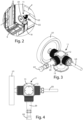
figure 2 is a detailed view extracted fromfigure 1 ; -
figure 3 is an isometric view of the operating device with outputs at different rotational speeds shown infigures 1 and2 ; -
figure 4 is a top-plan view of the operating device with outputs at different rotational speeds illustrated infigure 3 ; -
figure 5 is a side view of the operating device with outputs at different rotational speeds represented infigures 3 and 4 ; -
figure 6 is a sectional view along the section line A-A indicated infigure 5 ; -
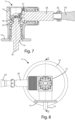
figure 7 is a sectional view along the section line B-B indicated infigure 5 ; -
figure 8 is a further side view of the operating device with outputs at different rotational speeds illustrated infigure 3 ; -
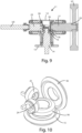
figure 9 is a sectional view along the section line C-C indicated infigure 8 ; and -
figure 10 is an axonometric view showing, schematically, the kinematic mechanism with gears for the transformation of the rotary motion, with which the operating device with outputs at differentiated rotation speeds shown infigures 3-9 is equipped; for clarity of graphic representation, the teeth of the gear wheels shown therein are not shown infigure 10 . - In the various figures, similar parts will be indicated with the same reference numbers.
- With reference to the enclosed
figures, 1 indicates a through-feed machine tool for working pieces made of wood, glass, plastic material, metal or other materials. - Essentially, this machine tool 1 comprises a
frame 2, in which anoperating station 3 is provided, arranged between aninput area 4, assigned to receive a piece P to be machined, and an exit area 5, for picking up the piece P worked through theoperating station 3. - In the machine tool 1 there is also provided with a
movement system 6 for moving the piece P, according to an advancement direction A parallel to a first axis X, from theentry area 4 to the exit area 5 making it pass through theoperating station 3. - This
handling system 6 can comprise, for example, aroller conveyor 6a (namely, a series of mutually parallel and adjacent rollers) and a gripping and thrustingmember 6b for grasping the piece P arranged on theroller conveyor 6a and pushing it according to the aforesaid advancement direction A. - The
aforementioned operating station 3 comprises, on the other hand, aframe 7, on which it is mounted, by means of aguide system 8, asupport member 9, movable along a second Y axis, orthogonal to the first X axis, and along a third Z axis orthogonal to the first X axis and the second Y axis. - An
electrospindle unit 10 is mounted on one end of thesupport member 9 for rotation around a rotation axis parallel to the second Y axis. - An
operative device 11 according to the present invention is mounted at one end of the electro-spindle unit 10, so that thisoperative device 11 can rotate around the rotation axis A1 described below and indicated infigure 7 , with respect to the electro-spindle unit 10, so as to be able to vary the orientation of the sameoperative device 11 on a plane orthogonal to the rotation axis A1. - In particular, this
operative device 11 comprises anouter casing 12 provided, at one of its ends, with aflange 13 to allow it to be connected to the electro-spindle unit 10, thisflange 13 being able to rotate around said axis A1 by rotary orientation members, made according to known methods, forming part of said electro-spindle unit 10. - Inside the
outer casing 12 there is an end portion of aninput shaft 14, i.e., a driving shaft, rotating around a relative rotation axis A1 and passing through theflange 13. - A first
toothed wheel 15 and a secondtoothed wheel 16 are mounted coaxially and rigidly on theinput shaft 14, having a diameter of the relative toothed part smaller than the diameter of the toothed part of the firsttoothed wheel 15. - Consequently, the first
toothed wheel 15 and the secondtoothed wheel 16 are also coaxial with each other. - The
operative device 11 also comprises afirst output shaft 17, i.e. a first driven shaft, rotatable around a respective rotation axis A2, orthogonal to the rotation axis A1 of theinput shaft 14. - At one end of the
first output shaft 17, a thirdtoothed wheel 18 is mounted coaxially and rigidly, meshed with the aforementioned firsttoothed wheel 15. - At the end of the
first output shaft 17, opposite to that on which the thirdtoothed wheel 18 is mounted, connection means 19 are provided to allow the connection with a first tool U1, such as, for example, a hogging. - The transmission ratio existing between the first
toothed wheel 15 and the thirdtoothed wheel 18 is 1:1, in order to have a high cutting torque in the first tool U1. - The
operative device 11 also comprises asecond output shaft 20, i.e. a second driven shaft, rotatable about a respective rotation axis A3, orthogonal to the rotation axis A1 of theinput shaft 14, and coplanar to the rotation axis A2 of thefirst output shaft 17. - At one end of the
second output shaft 20 is mounted, coaxially and rigidly, afourth gear wheel 21, conical, meshed with the aforesaid secondtoothed wheel 16, and having an outer diameter of the relative toothed part smaller than the outer diameter of the toothed part of the thirdtoothed wheel 18. - At the end of the
second output shaft 20, opposite to that on which the fourthtoothed wheel 21 is mounted, connection means 22 are provided, to allow connection with a second tool U2, such as for example a dovetail cutter. - The transmission ratio existing between the second
toothed wheel 16 and the fourthtoothed wheel 21 is 2:1, in order to have a higher rotation speed of the second tool U2, to obtain a better surface finish in the piece P being machined through the second tool U2. - In the
operative device 11 there is also provided athird output shaft 23, i.e. a third driven shaft, rotatable around a respective rotation axis A4, orthogonal to the rotation axis A1 of theinput shaft 14, and coplanar to the rotation axis A2 of thefirst output shaft 17 and to the rotation axis A3 of thesecond output shaft 20. - Therefore, the rotation axis A2 of the
first output shaft 17, the rotation axis A3 of thesecond output shaft 20, and the rotation axis A4 of thethird output shaft 23 lie in the same plane orthogonal to the rotation axis A1 of theinput shaft 14. - At one end of the
third output shaft 23 it is mounted, coaxially and rigidly, a fifthtoothed wheel 24, conical, meshed with the aforesaid secondtoothed wheel 16, and having an outer diameter of the relative toothed part equal to the outer diameter of the toothed part of the fourthtoothed wheel 21. - The aforesaid
outer casing 12 supports theinput shaft 14, thefirst output shaft 17, thesecond output shaft 20, and thethird output shaft 23, and contains within it the firsttoothed wheel 15, the secondtoothed wheel 16, the thirdtoothed wheel 18, the fourthtoothed wheel 21 and the fifthtoothed wheel 24. - At the end of the
third output shaft 23, opposite to that on which the fifthtoothed wheel 24 is mounted, connection means 25 are provided, to allow the connection with a third tool U3, such as, for example, an end mill. - The existing transmission ratio between the second
toothed wheel 16 and the fifthtoothed wheel 24 is 2:1, in order to have a higher rotation speed of the third tool U3, to obtain a better surface finish in the workpiece P through the third tool U3. - Preferably, the rotation axis A3 of the
second output shaft 20 is perpendicular to the rotation axis A2 of thefirst output shaft 17, and the rotation axis A4 of thethird output shaft 23 is perpendicular to said rotation axis A3 of thesecond output shaft 20, as shown infigure 6 . - During the operation of the machine tool 1, the piece P is made to advance according to the advancement direction A, through the
aforementioned movement system 6. - While the piece P is made to advance according to the advancement direction A, the electro-
spindle unit 10 and/or thesupport member 9 move in such a way as to allow the first tool U1 and/or the second tool U2 and/or the third tool U3 to carry out on the piece P the workings envisaged by the working program in execution. - For the execution of certain machining operations on the piece P, the electro-
spindle unit 10 and thesupport member 9 could remain stationary during the advancement of the piece P along the advancement direction A. - As can be inferred from the preceding description, the operating device according to the present invention makes it possible to have several tools at the same time and to make each of them work in the most appropriate manner or in the best manner on the basis of the specific work to be carried out on the piece, and the aesthetic results to be obtained on the piece itself.
- The present invention has been described for illustrative but not limitative purposes, according to its preferred embodiments, but it is to be understood that modifications and/or changes can be introduced by those skilled in the art without departing from the relevant scope as defined in the enclosed claims.
Claims (11)
- Operative device (11) for a machine tool (1) which is suitable for machining at least one piece (P) and provided with an electrospindle unit (10), said operative device (11) comprising:an inlet shaft (14) which is rotatable about a first rotation axis (A1) and connectable, in use, with said electrospindle unit (10) such that said inlet shaft (14) is rotated, in use, by said electrospindle unit (10) about said first rotation axis (A1);a first toothed wheel (15) being conical and a second toothed wheel (16) being conical, which are coaxially coupled to said inlet shaft (14);a first outlet shaft (17) which is rotatable about a second rotation axis (A2) being substantially orthogonal to said first rotation axis (A1) of said inlet shaft (14), wherein said first outlet shaft (17) is connectable, in use, with a first tool (U1);a third toothed wheel (18), conical, which is coaxially coupled to said first outlet shaft (17) and engaged with said first toothed wheel (15) such that, in use, said first toothed wheel (15) rotating about said first rotation axis (A1) of said inlet shaft (14) causes said third toothed wheel (18) to rotate about said second rotation axis (A2) of said first outlet shaft (17) based on a first gear ratio of the rotary motion;a second outlet shaft (20) which is rotatable about a third rotation axis (A3) being substantially orthogonal to said first rotation axis (A1) of said inlet shaft (14), wherein said second outlet shaft (20) is connectable, in use, with a second tool (U2), and wherein said third rotation axis (A3) of said second outlet shaft (20) and said second rotation axis (A2) of said first outlet shaft (17) are substantially coplanar;a fourth toothed wheel (21), conical, which is coaxially mounted to said second outlet shaft (20) and engaged with said second toothed wheel (16) such that, in use, said second toothed wheel (16) rotating about said first rotation axis (A1) of said inlet shaft (14) causes said fourth toothed wheel (21) to rotate about said third rotation axis (A3) of said second outlet shaft (20) based on a second gear ratio of the rotary motion which is different from said first gear ratio of the rotary motion; anda supporting and containing structure (12) which supports said inlet shaft (14), said first outlet shaft (17) and said second outlet shaft (20) and contains said first toothed wheel (15), said second toothed wheel (16), said third toothed wheel (18) and said fourth toothed wheel (21).
- Operative device (11) according to claim 1, characterized in that said second outlet shaft (20) rotates faster than said first outlet shaft (17), based on said first gear ratio and second gear ratio.
- Operative device (11) according to any one of preceding claims, characterized in that said third rotation axis (A3) of said second outlet shaft (20) is substantially at 90 degrees with respect to said second rotation axis (A2) of said first outlet shaft (17).
- Operative device (11) according to any one of preceding claims, characterized in that said first outlet shaft (17) comprises connection means (19) to allow, in use, the connection with a first tool (U1).
- Operative device (11) according to any one of preceding claims, characterized in that said second outlet shaft (20) comprises connection means (22) to allow, in use, the connection with a second tool (U2).
- Operative device (11) according to any one of preceding claims, characterized in that it comprises:a third outlet shaft (23) which is rotatable about a fourth rotation axis (A4) being substantially orthogonal to said first rotation axis (A1) of said inlet shaft (14), wherein said third outlet shaft (23) is connectable, in use, with a third tool (U3), and wherein said rotation axis (A4) of said third outlet shaft (23), said third rotation axis (A3) of said second outlet shaft (20) and said second rotation axis (A2) of said first outlet shaft (17) are substantially coplanar; anda fifth toothed wheel (24), conical, which is coaxially mounted to said third outlet shaft (23) and engaged to said second toothed wheel (16) such that, in use, said second toothed wheel (16) rotating about said first rotation axis (A1) of said inlet shaft (14) causes said fifth toothed wheel (24) to rotate about said rotation axis (A4) of said third outlet shaft (23) based on a third gear ratio of the rotary motion which is equal to said second gear ratio of the rotary motion.
- Operative device (11) according to claim 6, characterized in that said rotation axis (A4) of said third outlet shaft (23) is substantially at 90 degrees with respect to said third rotation axis (A3) of said second outlet shaft (20).
- Operative device (11) according to any one of preceding claims, characterized in that said first gear ratio of the rotary motion is approximately equal to 1:1.
- Operative device (11) according to any one of preceding claims, characterized in that said second gear ratio of the rotary motion is approximately equal to 2:1.
- Machine tool (1) for machining at least one workpiece (P), said machine tool (1) comprising:an electrospindle unit (10); andan operative device (11) according to any one of preceding claims, which is connected with said electrospindle unit (10) such that said electrospindle unit (10) is able to transmit a rotary motion to said operative device (11).
- Machine tool (1) according to claim 10, characterized in that said operative device (11) is rotatable with respect to said electrospindle unit (10).
Applications Claiming Priority (1)
| Application Number | Priority Date | Filing Date | Title |
|---|---|---|---|
| IT102021000031547A IT202100031547A1 (en) | 2021-12-16 | 2021-12-16 | Operating device with outputs at differentiated rotation speeds and machine tool including this operating device |
Publications (1)
| Publication Number | Publication Date |
|---|---|
| EP4197693A1 true EP4197693A1 (en) | 2023-06-21 |
Family
ID=80461847
Family Applications (1)
| Application Number | Title | Priority Date | Filing Date |
|---|---|---|---|
| EP22212477.8A Pending EP4197693A1 (en) | 2021-12-16 | 2022-12-09 | Operating device with differentiated rotational speed outputs and machine tool including such operating device |
Country Status (2)
| Country | Link |
|---|---|
| EP (1) | EP4197693A1 (en) |
| IT (1) | IT202100031547A1 (en) |
Citations (4)
| Publication number | Priority date | Publication date | Assignee | Title |
|---|---|---|---|---|
| DE1022076B (en) * | 1955-08-17 | 1958-01-02 | Karl Schwendenwein | Turret head for single-spindle machines |
| EP0458728A1 (en) * | 1990-05-22 | 1991-11-27 | Hh Patent A/S | Spindle drive |
| EP1270145A2 (en) * | 2001-06-22 | 2003-01-02 | Traub Drehmaschinen GmbH | Machine tool with rotatable multi-tool holder |
| EP3040145A1 (en) * | 2014-12-29 | 2016-07-06 | Freni Brembo S.p.A. | Milling method for making grooves along a cavity which extends in a workpiece |
-
2021
- 2021-12-16 IT IT102021000031547A patent/IT202100031547A1/en unknown
-
2022
- 2022-12-09 EP EP22212477.8A patent/EP4197693A1/en active Pending
Patent Citations (4)
| Publication number | Priority date | Publication date | Assignee | Title |
|---|---|---|---|---|
| DE1022076B (en) * | 1955-08-17 | 1958-01-02 | Karl Schwendenwein | Turret head for single-spindle machines |
| EP0458728A1 (en) * | 1990-05-22 | 1991-11-27 | Hh Patent A/S | Spindle drive |
| EP1270145A2 (en) * | 2001-06-22 | 2003-01-02 | Traub Drehmaschinen GmbH | Machine tool with rotatable multi-tool holder |
| EP3040145A1 (en) * | 2014-12-29 | 2016-07-06 | Freni Brembo S.p.A. | Milling method for making grooves along a cavity which extends in a workpiece |
Also Published As
| Publication number | Publication date |
|---|---|
| IT202100031547A1 (en) | 2023-06-16 |
Similar Documents
| Publication | Publication Date | Title |
|---|---|---|
| JP5043935B2 (en) | Equipment for cutting rod-like or tubular workpieces | |
| JPH0327342B2 (en) | ||
| CN217913919U (en) | Numerical control turntable type multi-station tool grinding machine | |
| EP2377646A1 (en) | Device for finishing edges and/or outer surfaces of workpieces | |
| JP3078869B2 (en) | Plate processing machine | |
| FR2473941B1 (en) | ||
| JPS6071143A (en) | Device for driving spindle in wood working machine | |
| JPS5856701A (en) | Machine tool | |
| US3595108A (en) | Apparatus for imparting a non-circular shape to an article | |
| US3422966A (en) | Method of feeding blanks to machine tools and device for realization of this method | |
| US4116095A (en) | Metal sawing or milling machine | |
| US2086492A (en) | Machine for working on curved shafts or the like | |
| JPH0847817A (en) | Improved lathe for forming linear and spiral thread | |
| IT202100031547A1 (en) | Operating device with outputs at differentiated rotation speeds and machine tool including this operating device | |
| CN207840666U (en) | A kind of carrying roller axis machining apparatus of numerically-controlled machine tool | |
| CN107116239A (en) | A kind of radian-adjustable arc lathe tool and application method | |
| SU1715520A1 (en) | Numerically controlled universal gear manufacturing machine | |
| CN203649524U (en) | Pipe cutting device | |
| JPH07506303A (en) | Multi-spindle automatic lathe | |
| US3936980A (en) | Method of and apparatus for grinding wire | |
| USRE16903E (en) | Circular milling machine | |
| CN223789625U (en) | A steel plate slitting machine with easy-to-change cutting blades | |
| CN117299893B (en) | A bending processing device that facilitates loading and unloading | |
| CN215316212U (en) | Gravure plate-making version roller blank cutting device | |
| SU956105A1 (en) | Apparatus for cutting wire to measured lengthes |
Legal Events
| Date | Code | Title | Description |
|---|---|---|---|
| PUAI | Public reference made under article 153(3) epc to a published international application that has entered the european phase |
Free format text: ORIGINAL CODE: 0009012 |
|
| STAA | Information on the status of an ep patent application or granted ep patent |
Free format text: STATUS: THE APPLICATION HAS BEEN PUBLISHED |
|
| AK | Designated contracting states |
Kind code of ref document: A1 Designated state(s): AL AT BE BG CH CY CZ DE DK EE ES FI FR GB GR HR HU IE IS IT LI LT LU LV MC ME MK MT NL NO PL PT RO RS SE SI SK SM TR |
|
| STAA | Information on the status of an ep patent application or granted ep patent |
Free format text: STATUS: REQUEST FOR EXAMINATION WAS MADE |
|
| 17P | Request for examination filed |
Effective date: 20231213 |
|
| RBV | Designated contracting states (corrected) |
Designated state(s): AL AT BE BG CH CY CZ DE DK EE ES FI FR GB GR HR HU IE IS IT LI LT LU LV MC ME MK MT NL NO PL PT RO RS SE SI SK SM TR |