EP4197461A1 - Medical instrument - Google Patents
Medical instrument Download PDFInfo
- Publication number
- EP4197461A1 EP4197461A1 EP21214904.1A EP21214904A EP4197461A1 EP 4197461 A1 EP4197461 A1 EP 4197461A1 EP 21214904 A EP21214904 A EP 21214904A EP 4197461 A1 EP4197461 A1 EP 4197461A1
- Authority
- EP
- European Patent Office
- Prior art keywords
- wedge
- jaw
- instrument
- coupling portion
- proximal
- Prior art date
- Legal status (The legal status is an assumption and is not a legal conclusion. Google has not performed a legal analysis and makes no representation as to the accuracy of the status listed.)
- Granted
Links
Images


Classifications
-
- A—HUMAN NECESSITIES
- A61—MEDICAL OR VETERINARY SCIENCE; HYGIENE
- A61B—DIAGNOSIS; SURGERY; IDENTIFICATION
- A61B17/00—Surgical instruments, devices or methods
- A61B17/28—Surgical forceps
- A61B17/2812—Surgical forceps with a single pivotal connection
- A61B17/282—Jaws
-
- A—HUMAN NECESSITIES
- A61—MEDICAL OR VETERINARY SCIENCE; HYGIENE
- A61B—DIAGNOSIS; SURGERY; IDENTIFICATION
- A61B17/00—Surgical instruments, devices or methods
- A61B17/28—Surgical forceps
- A61B17/2812—Surgical forceps with a single pivotal connection
- A61B17/2816—Pivots
-
- A—HUMAN NECESSITIES
- A61—MEDICAL OR VETERINARY SCIENCE; HYGIENE
- A61B—DIAGNOSIS; SURGERY; IDENTIFICATION
- A61B17/00—Surgical instruments, devices or methods
- A61B17/28—Surgical forceps
- A61B17/2812—Surgical forceps with a single pivotal connection
- A61B17/2841—Handles
-
- A—HUMAN NECESSITIES
- A61—MEDICAL OR VETERINARY SCIENCE; HYGIENE
- A61B—DIAGNOSIS; SURGERY; IDENTIFICATION
- A61B17/00—Surgical instruments, devices or methods
- A61B17/32—Surgical cutting instruments
- A61B17/3201—Scissors
-
- A—HUMAN NECESSITIES
- A61—MEDICAL OR VETERINARY SCIENCE; HYGIENE
- A61B—DIAGNOSIS; SURGERY; IDENTIFICATION
- A61B17/00—Surgical instruments, devices or methods
- A61B2017/0046—Surgical instruments, devices or methods with a releasable handle; with handle and operating part separable
- A61B2017/00473—Distal part, e.g. tip or head
-
- A—HUMAN NECESSITIES
- A61—MEDICAL OR VETERINARY SCIENCE; HYGIENE
- A61B—DIAGNOSIS; SURGERY; IDENTIFICATION
- A61B17/00—Surgical instruments, devices or methods
- A61B2017/00477—Coupling
-
- A—HUMAN NECESSITIES
- A61—MEDICAL OR VETERINARY SCIENCE; HYGIENE
- A61B—DIAGNOSIS; SURGERY; IDENTIFICATION
- A61B17/00—Surgical instruments, devices or methods
- A61B17/28—Surgical forceps
- A61B17/29—Forceps for use in minimally invasive surgery
- A61B2017/2926—Details of heads or jaws
- A61B2017/2931—Details of heads or jaws with releasable head
-
- B—PERFORMING OPERATIONS; TRANSPORTING
- B26—HAND CUTTING TOOLS; CUTTING; SEVERING
- B26B—HAND-HELD CUTTING TOOLS NOT OTHERWISE PROVIDED FOR
- B26B13/00—Hand shears; Scissors
- B26B13/04—Hand shears; Scissors with detachable blades
Definitions
- the coupling portion is a wedge-shaped protrusion and the complementary coupling portion is a complementary wedge-shaped recess, or vice versa, wherein the wedge-shaped protrusion comprises two wedge surfaces opposing each other along a medial/lateral axis, wherein the opposing wedge surfaces are inclined in proximal direction toward each other by a first angle of inclination, and wherein the opposing wedge surfaces are inclined inwardly toward each other by a second angle of inclination.
- the wedge-shaped recess is configured to snugly receive the wedge-shaped protrusion.
- the wedge-shaped protrusion is configured to snugly fit into the wedge-shaped recess.
- the inclination of the wedge surfaces in proximal direction causes a form fit in distal direction and a friction fit in proximal direction.
- Said form fit in distal direction prevents the jaw member from being pulled off the branch member in distal direction.
- Said frictional connection in proximal direction counteracts a relative movement of the jaw member in the proximal direction.
- the wedge-shaped protrusion is formed on the branch member and the wedge-shaped recess is formed on the jaw member. In another embodiment, the wedge-shaped protrusion is formed on the jaw member and the wedge-shaped recess is formed on the branch member.
- the wedge-shaped recess 13 is complementary to the wedge-shaped protrusion 12 with respect to its shape, form and size and will be described in more detail further below.
- the proximal end surface 18 is perpendicular with respect to the vertical longitudinal center plane and inclined with respect to a vertical transverse center plane which extends along the medial/lateral axis ML and the superior/inferior axis SI.
- a vertical transverse center plane which extends along the medial/lateral axis ML and the superior/inferior axis SI.
- such an inclination of the proximal end surface 18 is not mandatory.
- the wedge-shaped recess 13 also comprises an inferior (bottom) surface 17'.
- a bottom surface is not mandatory.
- the wedge-shaped recess 13 is open in superior direction.
- the jaw member 9 is securely attachable to the branch member 8 by bringing the wedge-shaped protrusion 12 into engagement with the wedge-shaped recess 13. In order to do so, the jaw member 9 is moved outwardly, i.e., from inside to outside with respect to the movement direction of the instrument mouth M, relative to the branch member 8. Once the wedge-shaped protrusion 12 is snugly received within the wedge-shaped recess 13, the opposing wedge surfaces 14, 15 form-fittingly and frictionally engage with the complementary wedge surfaces 14', 15' of the wedge-shaped recess 13. Being attached to the branch member 8, the jaw member 9 is form-fittingly attached in distal direction and superior direction (outward) and securely held in inferior direction (inward) due to the frictional engagement between the wedge surfaces 14, 14' and 15, 15', respectively.
Landscapes
- Health & Medical Sciences (AREA)
- Surgery (AREA)
- Life Sciences & Earth Sciences (AREA)
- Medical Informatics (AREA)
- Nuclear Medicine, Radiotherapy & Molecular Imaging (AREA)
- Engineering & Computer Science (AREA)
- Biomedical Technology (AREA)
- Heart & Thoracic Surgery (AREA)
- Molecular Biology (AREA)
- Animal Behavior & Ethology (AREA)
- General Health & Medical Sciences (AREA)
- Public Health (AREA)
- Veterinary Medicine (AREA)
- Ophthalmology & Optometry (AREA)
- Pathology (AREA)
- Surgical Instruments (AREA)
Abstract
Description
- The invention relates to a medical instrument, comprising two instrument branches pivotally coupled to each other, each of the instrument branches having a proximal handling portion and a distal jaw portion, the distal jaw portions forming an instrument mouth which is movable, by a pivotal movement of the instrument branches, between a closed state, in which the jaw portions are moved inwardly toward each other, and an open state, in which the jaw portions are moved outwardly away from each other, wherein at least one of the instrument branches comprises a branch member and a jaw member, the branch member being elongated along a proximal/distal axis and having one of the proximal handling portions and a distal coupling portion, the jaw member forming one of the jaw portions and having a proximal complementary coupling portion, and wherein the coupling portion and the complementary coupling portion form a releasable connection to exchangeably attach the jaw member to the branch member.
-
CN 207898524 U discloses a medical instrument in the form of a detachable interchangeable surgical scissor. The surgical scissor comprises two instrument branches pivotally coupled to each other. Each of the instrument branches comprises an elongated branch member and a jaw member, wherein the jaw member is in the form of a blade. The blades are exchangeably attached to the respective branch member by means of a dovetail joint which is fastened with a separate screw member. Hence, exchanging the blades requires medical staff to loosen and fasten the screw members with the help of an additional mechanical tool, e.g. a screwdriver or the like. - It is an object of the present invention to provide a medical instrument of the type mentioned at the beginning, which has a simplified structure and enables a particularly secure attachment as well as a simple and quick exchange of the jaw member.
- This object is solved by providing a medical instrument with the features of
claim 1. Preferred embodiments are defined in the dependent claims. - According to the invention the coupling portion is a wedge-shaped protrusion and the complementary coupling portion is a complementary wedge-shaped recess, or vice versa, wherein the wedge-shaped protrusion comprises two wedge surfaces opposing each other along a medial/lateral axis, wherein the opposing wedge surfaces are inclined in proximal direction toward each other by a first angle of inclination, and wherein the opposing wedge surfaces are inclined inwardly toward each other by a second angle of inclination.
- The invention eliminates the need of separate fastening means like screws, pins, fasteners, or the like to securely attach the jaw member to the branch member. This leads to a simplified structure of the medical instrument. The simplified structure allows to cut manufacturing effort and associated costs. In contrast to the prior art, designing the coupling portion and the complementary coupling portion according to the invention allows to attach and detach the jaw member without the use of tools and with only little manual effort. This saves time and labor and thus enables a simple and particularly quick exchange of the jaw member, if required.
- The wedge-shaped recess is configured to snugly receive the wedge-shaped protrusion. The wedge-shaped protrusion is configured to snugly fit into the wedge-shaped recess. It goes without saying that, since the wedge-shaped recess is complementary to the wedge-shaped protrusion, it comprises two wedge (recess) surfaces being complementary to the two wedge surfaces of the wedge-shaped protrusion. Hence, the two wedge (recess) surfaces oppose each other along the medial/lateral axis, are inclined in proximal direction toward each other by the first angle of inclination and are inclined inwardly toward each other by the second angle of inclination.
- The wedge surfaces of the wedge-shaped protrusion interact with the wedge (recess) surfaces of the wedge-shaped recess by positive engagement (form fit) and friction engagement (friction fit). Put in other words, the jaw member is exchangeably attached to the branch member by positive engagement and by friction engagement between the wedge-shaped protrusion and the complementary wedge-shaped recess.
- The inclination of the wedge surfaces in proximal direction causes a form fit in distal direction and a friction fit in proximal direction. Said form fit in distal direction prevents the jaw member from being pulled off the branch member in distal direction. Said frictional connection in proximal direction counteracts a relative movement of the jaw member in the proximal direction.
- The (additional) inclination of the wedge surfaces in inward direction, i.e., in closing direction of the instrument mouth, causes a form fit in outward direction, i.e., in opening direction of the instrument mouth, and a friction fit in inward direction. Said form fit in outward direction prevents the jaw member from moving relative to the branch member in outward direction. Said friction fit in inward direction counteracts a relative movement of the jaw member in inward direction, especially when the instrument mouth is opened.
- In one embodiment, the wedge-shaped protrusion is formed on the branch member and the wedge-shaped recess is formed on the jaw member. In another embodiment, the wedge-shaped protrusion is formed on the jaw member and the wedge-shaped recess is formed on the branch member.
- In one embodiment, the first angle of inclination measures between 10° and 30°, preferably between 15° and 25°, more preferably between 17.5° and 22.5°. The inventors have recognized that the above value ranges are particularly advantageous. Selecting a rather large first angle of inclination allows for a reliable positive engagement (form fit) of the jaw member in distal direction. Selecting a rather small first angle of inclination leads to relatively high frictional forces between the wedge surfaces and the wedge recess surfaces in proximal direction. The inventors have found that selecting the first angle of inclination between 17.5° and 22.5° leads to an optimum with respect to both, positive and frictional engagement.
- In one embodiment, the second angle of inclination measures between 10° and 30°, preferably between 15° and 25°, more preferably between 17.5° and 22.5°. Selecting a rather small second angle of inclination results in relatively high frictional forces in inward direction. The higher the frictional forces in inward direction, the more reliable the jaw member is held at the distal end of the branch member in the open state of the instrument mouth. However, a too small second angle of inclination may lead to excessive frictional forces which can result in the jaw member being difficult to detach from the branch member. The inventors have recognized that selecting the second angle of inclination between 17.5° and 22.5° allows for a secure frictional engagement in inward direction and a relatively easy detachment at the same time.
- Another object of the present invention is to provide a kit that allows to reduce manufacturing costs and purchasing costs for medical instruments.
- This object is solved by providing a kit with the features of claim 4.
- The kit comprises a medical instrument according to the invention. The medical instrument can be, in particular, a hand instrument (for example as per
figure 1 ), an endoscopic instrument and/or a robotic arm instrument. The kit also comprises a plurality of different jaw members, the different jaw members comprising identical complementary coupling portions configured for releasable connection to the coupling portion of the at least one branch member. The kit according to the invention allows to optimize the manufacturing process. It also allows to manage and choose the different jaw members separately from the remaining parts and portions of the medical instrument at the medical environment, for example in the surgical theater. Hence, medical staff is able to select and attach the jaw member of the plurality of different jaw members most suitable for a particular medical and/or surgical task. Put in other words, the kit may serve as an exchangeable interface for different handles. The different jaw members are identical with respect to the complementary coupling portion. In one embodiment, the coupling portions are formed as wedge-shaped recesses. In another embodiment, the complementary coupling portions are formed as wedge-shaped protrusions. The wedge-shaped recesses (or wedge-shaped protrusions) of the different jaw members are identical in dimensional features such as size, form, shape. In embodiments, the different jaw members differ with respect to size, shape, form, function or the like. In one embodiment, the different jaw members are supplied pre-sterilized and configured for single use. In one embodiment, the different jaw members a configured for multiple use. In one embodiment, the different jaw members are made of a metal material. In one embodiment, the different jaw members are made of a plastic material. - In the following, embodiments of the invention are described in detail with reference to the drawings. Throughout the drawings, same elements are denoted with same reference numerals. The drawings schematically show:
- fig. 1
- a perspective view of an embodiment of a medical instrument according to the invention, the medical instrument having two instrument branches;
- fig. 2
- a distal portion of one of the instrument branches in enlarged detail, the instrument branch having a branch member and a jaw member, the jaw member being shown in a longitudinal sectional view;
- fig. 3
- the distal region according to
fig. 2 in a perspective view; - fig. 4
- an enlarged perspective view of the distal end of the branch member with a coupling portion formed as wedge-shaped protrusion and configured for releasable connection with a complementary wedge-shaped recess of the jaw member;
- figs. 5, 6, 7
- the wedge-shaped protrusion in a simplified top view (
fig. 5 ), front view (fig. 6 ) and bottom view (fig. 7 ); - figs. 8, 9
- the wedge-shaped recess of the jaw member in a simplified top view (
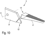
fig. 8 ) and rear view (fig. 9 ); - fig. 10
- the distal region of the remaining instrument branch of the medical instrument according to
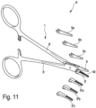
fig. 1 in a view similar tofig. 3 , and - fig. 11
- a perspective view of an embodiment of a kit according to the invention.
- According to
fig. 1 , amedical instrument 1 comprises twoinstrument branches first instrument branch 2 and asecond instrument branch 3. The twoinstrument branches instrument branches instrument branches proximal handling portion 4, 5 and adistal jaw portion 6, 7. The handlingportions 4, 5 can also be denoted as first handling portion 4 andsecond handling portion 5. Thejaw portions 6, 7 can also be denoted as first jaw portion 6 andsecond jaw portion 7. Thedistal jaw portions 6, 7 form an instrument mouth M which is movable between an open state (seefig. 1 ) and a closed state (not depicted in the figures). The instrument mouth M is movable by means of a relative pivotal movement of theinstrument branches jaw portions 6, 7 are moved inwardly toward each other. For opening the instrument mouth M, thejaw portions 6, 7 are moved outwardly away from each other. - In the embodiment shown, the
medical instrument 1 is a surgical needle holder. In other embodiments (not shown in the figures), the medical instrument is forceps, a clamp, scissors, or the like. Put in other words, themedical instrument 1 is forceps-like or scissor-like and allows to grip, hold and/or cut medical grade materials or body tissue between thejaw portions 6, 7. - In the embodiment shown, the
medical instrument 1 is configured for manual operation in an open surgery. In other embodiments (not shown in the figures), the medical instrument is an endoscopic instrument and/or a robotic arm instrument configured for robotic surgery. - In prior art, medical instruments like needle holders, forceps, clamps or scissors oftentimes feature a two-part design. In such a two-part design each of the instrument branches is formed as a single part with the respective handling portion and jaw portion being formed integral at the proximal end and distal end of the instrument branch, respectively.
- In order to facilitate the manufacturing process and to reduce costs, the
medical instrument 1 has a modular design instead, wherein at least one of the twoinstrument branches - In the embodiment shown, the
first instrument branch 2 comprises abranch member 8 and a jaw member 9 (seefigs. 2 ,3 ). Thebranch member 8 comprises a distal coupling portion 10. Thejaw member 9 comprises a proximal complementary coupling portion 11. The coupling portion 10 and the complementary coupling portion 11 form a releasable connection C to exchangeably attach thejaw member 9 to thebranch member 8. Hence, thejaw member 9 is attachable to thebranch member 8 by establishing the connection C between the coupling portion 10 and the complementary coupling portion 11. Releasing the connection C allows to detach thejaw member 9 from thebranch member 8. - In the prior art, it is known to exchangeably attach the jaw member to the branch member by means of a dovetail joint, wherein the dovetail joint is fastened by means of an additional screw member. The resulting configuration is rather complicated and requires loosening and fastening of the separate screw member manually with the help of a tool to exchange the jaw member.
- In order to arrive at a simplified structure of the medical instrument and to allow a particularly secure attachment as well as a simple and quick exchange of the
jaw member 9, the coupling portion 10 is a wedge-shapedprotrusion 12 and the complementary coupling portion 11 is a complementary wedge-shapedrecess 13, wherein the wedge-shapedprotrusion 12 comprises twowedge surfaces figs. 3, 4 ), wherein the opposing wedge surfaces 14, 15 are inclined in proximal direction toward each other by a first angle of inclination α, and wherein the opposing wedge surfaces 14, 15 are inclined inwardly toward each other by a second angle of inclination β. - The wedge-shaped
recess 13 is complementary to the wedge-shapedprotrusion 12 with respect to its shape, form and size and will be described in more detail further below. - The
branch member 8 is elongated between the wedge-shapedprotrusion 12 and the first proximal handling portion 4. The wedge-shapedprotrusion 12 is an integral portion of thebranch member 8. - In the embodiment shown, the proximal handling portion 4 is integral with the
branch member 8. In an embodiment not depicted in the figures, the handling portion is formed as a separate unit and detachably attached to the branch member. - The proximal handling portion 4 forms the proximal end of the
branch member 8 and the wedge-shapedprotrusion 12 forms the distal end of thebranch member 8. Thebranch member 8 is elongated along a proximal/distal axis PD. - The two
wedge surfaces medial wedge surface 14 andlateral wedge surface 15. - The medial/lateral axis ML and the proximal/distal axis PD are oriented perpendicular to each other. Together with a superior/inferior axis SI said axes PD, ML define a Cartesian reference axes system.
Figs. 5, 6 further clarify the orientation of said axes PD, ML, SI. The proximal/distal axis PD extends between a proximal side (end) P and a distal side (end) D. The medial/lateral axis ML extends between a medial side M and a lateral side L. The superior/inferior axis SI extends between a superior (upper) side S and an inferior (lower) side I. - In the embodiment shown, the wedge-shaped
protrusion 12 is symmetrical with respect to a vertically oriented central longitudinal plane of thebranch member 8. Said plane extends along the proximal/distal axis PD and along the superior/inferior axis SI. The same holds mutatis mutandis for the complementary wedge-shapedrecess 13 of thejaw member 9. - Due to the first angle of inclination α the opposing wedge surfaces 14, 15 converge towards each other in proximal direction and diverge from each other in distal direction.
- In the embodiment shown, the first angle of inclination α measures 20°. In other embodiments not depicted in the figures, the first angle of inclination α measures between 10° and 30°.
- The second angle of inclination β causes the opposing wedge surfaces 14, 15 to converge in inward direction and to diverge in outward direction. Put in other words, the opposing wedge surfaces 14, 15 converge with respect to the closing direction of the instrument mouth M and diverge in opening direction of the instrument mouth M. In yet other words, the opposing wedge surfaces 14, 15 converge towards each other in inferior direction and diverge from each other in superior direction.
- In the embodiment shown, the second angle of inclination β measures 20°. In other embodiments not shown in the figures, the second angle of inclination β measures between 10° and 30°.
- In the following, further details of the wedge-shaped
protrusion 12 will be described with reference tofigs. 4 to 7 . - In the embodiment shown, the wedge-shaped
protrusion 12 also comprises a superior (upper)surface 16 and an opposing inferior (lower)surface 17. Thesuperior surface 16 and theinferior surface 17 oppose each other along the superior/inferior axis SI. The wedge-shapedprotrusion 12 also has aproximal end surface 18. In the embodiment shown, thesuperior surface 16 and theinferior surface 17 are parallel to each other and with respect to a horizontal longitudinal center plane which extends along the proximal/distal axis PD and the medial/lateral axis ML. However, such an orientation of thesuperior surface 16 and theinferior surface 17 is not mandatory. In the embodiment shown, theproximal end surface 18 is perpendicular with respect to the vertical longitudinal center plane and inclined with respect to a vertical transverse center plane which extends along the medial/lateral axis ML and the superior/inferior axis SI. However, such an inclination of theproximal end surface 18 is not mandatory. - The complementary wedge-shaped
recess 13 is configured to snugly receive the wedge-shapedprotrusion 12. Since the wedge-shapedrecess 13 is complementary to the wedge-shapedprotrusion 12 with respect to size, shape and form, it comprises opposing wedge surfaces (wedge recess surfaces) configured for positive engagement and frictional engagement with the wedge surfaces 14, 15 of the wedge-shapedprotrusion 12. - With respect to
figs. 8 and 9 the wedge-shapedrecess 13 comprises opposing wedge recess surfaces 14', 15' which can also be denoted as medial wedge recess surface 14' and medial wedge recess surface 15'. Said surfaces 14', 15' oppose each other along the medial/lateral axis ML and are inclined in proximal direction toward each other by the first angle of inclination α. Moreover, the opposing surfaces 14', 15' are inclined inwardly toward each other by the second angle of inclination β. What has already been disclosed about the inclination of the opposing wedge surfaces 14, 15 of the wedge-shapedprotrusion 12 applies analogously to the inclination of the opposing wedge recess surfaces 14', 15'. - In the embodiment shown, the wedge-shaped
recess 13 also comprises an inferior (bottom) surface 17'. However, such a bottom surface is not mandatory. - The wedge-shaped
recess 13 is open in superior direction. - Starting from the configuration shown in
fig. 3 , thejaw member 9 is securely attachable to thebranch member 8 by bringing the wedge-shapedprotrusion 12 into engagement with the wedge-shapedrecess 13. In order to do so, thejaw member 9 is moved outwardly, i.e., from inside to outside with respect to the movement direction of the instrument mouth M, relative to thebranch member 8. Once the wedge-shapedprotrusion 12 is snugly received within the wedge-shapedrecess 13, the opposing wedge surfaces 14, 15 form-fittingly and frictionally engage with the complementary wedge surfaces 14', 15' of the wedge-shapedrecess 13. Being attached to thebranch member 8, thejaw member 9 is form-fittingly attached in distal direction and superior direction (outward) and securely held in inferior direction (inward) due to the frictional engagement between the wedge surfaces 14, 14' and 15, 15', respectively. - Closing the instrument mouth M and pressing the
jaw portions 5, 6 onto each other pushes the wedge-shapedprotrusion 12 further into the wedge-shapedrecess 13 and causes an enhanced frictional fit. The resulting frictional forces counteract an unintended detachment of thejaw member 9. In the open state of the instrument mouth M, for example, said frictional forces hinder thejaw member 9 from falling off thebranch member 8. - In the embodiment shown, the
second instrument branch 3 has a similar modular structure with a second branch member 8' comprising a wedge-shaped protrusion 12' and a second jaw member 9' comprising a wedge-shaped recess 13'. This allows an even further simplified structure and yet improved versatility of themedical instrument 1. With respect to further structural and functional features of the wedge-shaped protrusion 12' and the wedge-shaped recess 13' reference is made to the above disclosure. The disclosure with respect to the wedge-shapedprotrusion 12 and the wedge-shaped recess 13' applies mutatis mutandis concerning the (further) wedge-shaped protrusion 12' and the (further) wedge-shaped recess 13' of thesecond instrument branch 3, respectively. - According to
fig. 11 a kit K comprises themedical instrument 1 and a plurality ofdifferent jaw members recess 13. However, the wedge-shapedrecesses 13 are not depicted in greater detail infig. 11 . Said different jaw members differ with respect to size, shape, form and/or function. In this context, thedifferent jaw members upper jaw member 9a, second alternativeupper jaw member 9b and third alternativeupper jaw member 9c. Each of said alternative upper jaw members is detachably attachable to the (first)branch member 8 instead of the (first)jaw member 9. The different jaw members 9'a, 9'b, 9'c can also be denoted as first alternative lower jaw member 9'a, second alternative lower jaw member 9'b and third alternative lower jaw member 9'c. Said alternative lower jaw members are detachably attachable to the second branch member 8' instead of the second jaw member 9'.
Claims (4)
- A medical instrument (1), comprisingtwo instrument branches (2, 3) pivotally coupled to each other, each of the instrument branches (2, 3) having a proximal handling portion (4, 5) and a distal jaw portion (6, 7), the distal jaw portions (6, 7) forming an instrument mouth (M) which is movable, by a pivotal movement of the instrument branches (2, 3), between a closed state, in which the jaw portions (6, 7) are moved inwardly toward each other, and an open state, in which the jaw portions (6, 7) are moved outwardly away from each other,wherein at least one of the instrument branches (2, 3) comprises a branch member (8) and a jaw member (9), the branch member (8) being elongated along a proximal/distal axis (PD) and having one of the proximal handling portions (4, 5) and a distal coupling portion (10), the jaw member (9) forming one of the jaw portions (6, 7) and having a proximal complementary coupling portion (11),and wherein the coupling portion (10) and the complementary coupling portion (11) form a releasable connection (C) to exchangeably attach the jaw member (9) to the branch member (8),characterized in that the coupling portion (10) is a wedge-shaped protrusion (12) and in that the complementary coupling portion (11) is a complementary wedge-shaped recess (13), or vice versa,wherein the wedge-shaped protrusion (12) comprises two wedge surfaces (14, 15) opposing each other along a medial/lateral axis (ML), wherein the opposing wedge surfaces (14, 15) are inclined in proximal direction toward each other by a first angle of inclination (α), and wherein the opposing wedge surfaces (14, 15) are inclined inwardly toward each other by a second angle of inclination (β).
- The medical instrument (1) according to claim 1, characterized in that the first angle of inclination (α) measures between 10° and 30°, preferably between 15° and 25°, more preferably between 17.5° and 22.5°.
- The medical instrument (1) according to claim 1 or 2, characterized in that the second angle of inclination (β) measures between 10° and 30°, preferably between 15° and 25°, more preferably between 17.5° and 22.5°.
- A kit (K) comprising the medical instrument (1) according to any of the preceding claims and comprising a plurality of different jaw members (9a, 9b, 9c, 9'a, 9'b, 9'c), the different jaw members (9a, 9b, 9c, 9'a, 9'b, 9'c) comprising identical complementary coupling portions configured for releasable connection to the coupling portion of the at least one branch member (8).
Priority Applications (5)
| Application Number | Priority Date | Filing Date | Title |
|---|---|---|---|
| EP21214904.1A EP4197461B1 (en) | 2021-12-15 | 2021-12-15 | Medical instrument |
| ES21214904T ES2973983T3 (en) | 2021-12-15 | 2021-12-15 | medical instrument |
| CN202280083247.7A CN118401186B (en) | 2021-12-15 | 2022-12-14 | Medical apparatus and instruments |
| US18/719,469 US12521136B2 (en) | 2021-12-15 | 2022-12-14 | Medical instrument |
| PCT/EP2022/085868 WO2023111027A1 (en) | 2021-12-15 | 2022-12-14 | Medical instrument |
Applications Claiming Priority (1)
| Application Number | Priority Date | Filing Date | Title |
|---|---|---|---|
| EP21214904.1A EP4197461B1 (en) | 2021-12-15 | 2021-12-15 | Medical instrument |
Publications (2)
| Publication Number | Publication Date |
|---|---|
| EP4197461A1 true EP4197461A1 (en) | 2023-06-21 |
| EP4197461B1 EP4197461B1 (en) | 2023-12-13 |
Family
ID=79024164
Family Applications (1)
| Application Number | Title | Priority Date | Filing Date |
|---|---|---|---|
| EP21214904.1A Active EP4197461B1 (en) | 2021-12-15 | 2021-12-15 | Medical instrument |
Country Status (5)
| Country | Link |
|---|---|
| US (1) | US12521136B2 (en) |
| EP (1) | EP4197461B1 (en) |
| CN (1) | CN118401186B (en) |
| ES (1) | ES2973983T3 (en) |
| WO (1) | WO2023111027A1 (en) |
Citations (5)
| Publication number | Priority date | Publication date | Assignee | Title |
|---|---|---|---|---|
| US3670415A (en) * | 1970-06-12 | 1972-06-20 | Anthony T Rose | Surgical instrument |
| US4597385A (en) * | 1983-04-29 | 1986-07-01 | Watson Trevor F | Biopsy instrument |
| EP1187564A1 (en) * | 1999-06-21 | 2002-03-20 | Novare Surgical Systems, Inc. | Surgical clamp with replaceable clamp members |
| FR3029402A1 (en) * | 2014-12-08 | 2016-06-10 | Thomas Ondet | ORTHODONTIC FORCEPS |
| CN207898524U (en) | 2017-10-19 | 2018-09-25 | 德州雷奥巴赫医疗器械有限公司 | Detachable interchangeable operating scissors |
Family Cites Families (16)
| Publication number | Priority date | Publication date | Assignee | Title |
|---|---|---|---|---|
| JPS60149381U (en) * | 1984-03-15 | 1985-10-03 | 服部 實 | Sheath-shaped blade scissors |
| JPH084939Y2 (en) * | 1990-05-29 | 1996-02-14 | 株式会社サンギ | Indexable scissors |
| US5591182A (en) * | 1994-10-17 | 1997-01-07 | Applied Medical Resources Corporation | Atraumatic surgical clamping instrument |
| US20030171747A1 (en) * | 1999-01-25 | 2003-09-11 | Olympus Optical Co., Ltd. | Medical treatment instrument |
| US6387112B1 (en) * | 1999-06-18 | 2002-05-14 | Novare Surgical Systems, Inc. | Surgical clamp having replaceable pad |
| US6273902B1 (en) * | 1999-06-18 | 2001-08-14 | Novare Surgical Systems, Inc. | Surgical clamp having replaceable pad |
| US6228104B1 (en) * | 1999-06-18 | 2001-05-08 | Novare Surgical Systems, Inc. | Surgical clamp having replaceable pad |
| US7842045B2 (en) * | 2005-01-19 | 2010-11-30 | Applied Medical Resources Corporation | Single fire vascular clip applier with disposable jaw |
| US20070191713A1 (en) * | 2005-10-14 | 2007-08-16 | Eichmann Stephen E | Ultrasonic device for cutting and coagulating |
| US9072523B2 (en) * | 2010-11-05 | 2015-07-07 | Ethicon Endo-Surgery, Inc. | Medical device with feature for sterile acceptance of non-sterile reusable component |
| CN102058423B (en) | 2011-01-10 | 2013-02-13 | 天津大学 | Surgical scissors for surgical robot |
| US9039732B2 (en) * | 2011-07-11 | 2015-05-26 | Covidien Lp | Surgical forceps |
| US9028492B2 (en) * | 2011-08-18 | 2015-05-12 | Covidien Lp | Surgical instruments with removable components |
| US10456157B2 (en) * | 2015-08-26 | 2019-10-29 | Ethicon Llc | Ultrasonic surgical instrument clamp arm with snap-on clamp pad |
| CN208002861U (en) | 2017-03-18 | 2018-10-26 | 上海市中医医院 | A kind of replaceable Disposable scissors head medical operation is cut |
| CN213465224U (en) | 2020-05-18 | 2021-06-18 | 浙江大学 | A surgical forceps scissors |
-
2021
- 2021-12-15 ES ES21214904T patent/ES2973983T3/en active Active
- 2021-12-15 EP EP21214904.1A patent/EP4197461B1/en active Active
-
2022
- 2022-12-14 CN CN202280083247.7A patent/CN118401186B/en active Active
- 2022-12-14 WO PCT/EP2022/085868 patent/WO2023111027A1/en not_active Ceased
- 2022-12-14 US US18/719,469 patent/US12521136B2/en active Active
Patent Citations (5)
| Publication number | Priority date | Publication date | Assignee | Title |
|---|---|---|---|---|
| US3670415A (en) * | 1970-06-12 | 1972-06-20 | Anthony T Rose | Surgical instrument |
| US4597385A (en) * | 1983-04-29 | 1986-07-01 | Watson Trevor F | Biopsy instrument |
| EP1187564A1 (en) * | 1999-06-21 | 2002-03-20 | Novare Surgical Systems, Inc. | Surgical clamp with replaceable clamp members |
| FR3029402A1 (en) * | 2014-12-08 | 2016-06-10 | Thomas Ondet | ORTHODONTIC FORCEPS |
| CN207898524U (en) | 2017-10-19 | 2018-09-25 | 德州雷奥巴赫医疗器械有限公司 | Detachable interchangeable operating scissors |
Also Published As
| Publication number | Publication date |
|---|---|
| US20250049458A1 (en) | 2025-02-13 |
| CN118401186A (en) | 2024-07-26 |
| CN118401186B (en) | 2025-03-11 |
| EP4197461B1 (en) | 2023-12-13 |
| WO2023111027A1 (en) | 2023-06-22 |
| US12521136B2 (en) | 2026-01-13 |
| ES2973983T3 (en) | 2024-06-25 |
Similar Documents
| Publication | Publication Date | Title |
|---|---|---|
| US4669470A (en) | Surgical forceps/scissors | |
| US6010509A (en) | Patella resection drill and prosthesis implantation device | |
| GB2179288A (en) | Disposable surgical clamping instrument | |
| US4976617A (en) | Dental implant screw driver system | |
| US6910890B2 (en) | Dental plier design with offsetting jaw and pad elements for assisting in removing upper and lower teeth utilizing the dental plier design | |
| JPS6246184B2 (en) | ||
| EP2617368B1 (en) | Surgical needle holder | |
| US20100064862A1 (en) | Hand tool articulating apparatus with offset handle | |
| US5833697A (en) | Suture needle holding surgical instrument | |
| US12521136B2 (en) | Medical instrument | |
| EP1656893A2 (en) | Combined grip-cut tool | |
| JPWO2014091523A1 (en) | Medical instruments | |
| US6394805B1 (en) | Dental crown remover with basket | |
| US20120150198A1 (en) | Ergonomically Correct Needle Holder | |
| KR100334361B1 (en) | Retention Kit for Orthodontic Appliances | |
| CN214208539U (en) | Horizontal retention clamp for massive bones | |
| US12232756B2 (en) | Dual bone forceps | |
| CN219271060U (en) | Push-pull type quick loading and unloading scissors of surgical robot | |
| JP2017525535A (en) | Surgical forceps jaw brace with orientation indication | |
| CN221950027U (en) | Acetabular cup prosthesis and lining extraction forceps thereof | |
| CN221512238U (en) | Multipurpose orthodontic needle holder | |
| CA2492576C (en) | Dental pliers design with offsetting jaw and pad elements for assisting in removing upper and lower teeth and method for removing teeth utilizing the dental plier design | |
| Vickers | Microsurgery Instruments—A New Philosophy | |
| CN219557479U (en) | Mammary gland endoscope clamping forceps | |
| CN212118265U (en) | Free bone block tractive pincers of bone platform |
Legal Events
| Date | Code | Title | Description |
|---|---|---|---|
| PUAI | Public reference made under article 153(3) epc to a published international application that has entered the european phase |
Free format text: ORIGINAL CODE: 0009012 |
|
| STAA | Information on the status of an ep patent application or granted ep patent |
Free format text: STATUS: REQUEST FOR EXAMINATION WAS MADE |
|
| 17P | Request for examination filed |
Effective date: 20230427 |
|
| AK | Designated contracting states |
Kind code of ref document: A1 Designated state(s): AL AT BE BG CH CY CZ DE DK EE ES FI FR GB GR HR HU IE IS IT LI LT LU LV MC MK MT NL NO PL PT RO RS SE SI SK SM TR |
|
| GRAP | Despatch of communication of intention to grant a patent |
Free format text: ORIGINAL CODE: EPIDOSNIGR1 |
|
| STAA | Information on the status of an ep patent application or granted ep patent |
Free format text: STATUS: GRANT OF PATENT IS INTENDED |
|
| INTG | Intention to grant announced |
Effective date: 20230727 |
|
| RIC1 | Information provided on ipc code assigned before grant |
Ipc: B26B 13/04 20060101ALN20230714BHEP Ipc: A61B 17/29 20060101ALN20230714BHEP Ipc: A61B 17/3201 20060101ALI20230714BHEP Ipc: A61B 17/28 20060101AFI20230714BHEP |
|
| P01 | Opt-out of the competence of the unified patent court (upc) registered |
Effective date: 20230927 |
|
| GRAS | Grant fee paid |
Free format text: ORIGINAL CODE: EPIDOSNIGR3 |
|
| GRAA | (expected) grant |
Free format text: ORIGINAL CODE: 0009210 |
|
| STAA | Information on the status of an ep patent application or granted ep patent |
Free format text: STATUS: THE PATENT HAS BEEN GRANTED |
|
| AK | Designated contracting states |
Kind code of ref document: B1 Designated state(s): AL AT BE BG CH CY CZ DE DK EE ES FI FR GB GR HR HU IE IS IT LI LT LU LV MC MK MT NL NO PL PT RO RS SE SI SK SM TR |
|
| REG | Reference to a national code |
Ref country code: GB Ref legal event code: FG4D |
|
| REG | Reference to a national code |
Ref country code: CH Ref legal event code: EP |
|
| REG | Reference to a national code |
Ref country code: DE Ref legal event code: R096 Ref document number: 602021007663 Country of ref document: DE |
|
| REG | Reference to a national code |
Ref country code: IE Ref legal event code: FG4D |
|
| PG25 | Lapsed in a contracting state [announced via postgrant information from national office to epo] |
Ref country code: GR Free format text: LAPSE BECAUSE OF FAILURE TO SUBMIT A TRANSLATION OF THE DESCRIPTION OR TO PAY THE FEE WITHIN THE PRESCRIBED TIME-LIMIT Effective date: 20240314 |
|
| REG | Reference to a national code |
Ref country code: LT Ref legal event code: MG9D |
|
| PG25 | Lapsed in a contracting state [announced via postgrant information from national office to epo] |
Ref country code: LT Free format text: LAPSE BECAUSE OF FAILURE TO SUBMIT A TRANSLATION OF THE DESCRIPTION OR TO PAY THE FEE WITHIN THE PRESCRIBED TIME-LIMIT Effective date: 20231213 |
|
| REG | Reference to a national code |
Ref country code: NL Ref legal event code: MP Effective date: 20231213 |
|
| PG25 | Lapsed in a contracting state [announced via postgrant information from national office to epo] |
Ref country code: LT Free format text: LAPSE BECAUSE OF FAILURE TO SUBMIT A TRANSLATION OF THE DESCRIPTION OR TO PAY THE FEE WITHIN THE PRESCRIBED TIME-LIMIT Effective date: 20231213 Ref country code: GR Free format text: LAPSE BECAUSE OF FAILURE TO SUBMIT A TRANSLATION OF THE DESCRIPTION OR TO PAY THE FEE WITHIN THE PRESCRIBED TIME-LIMIT Effective date: 20240314 Ref country code: BG Free format text: LAPSE BECAUSE OF FAILURE TO SUBMIT A TRANSLATION OF THE DESCRIPTION OR TO PAY THE FEE WITHIN THE PRESCRIBED TIME-LIMIT Effective date: 20240313 |
|
| REG | Reference to a national code |
Ref country code: AT Ref legal event code: MK05 Ref document number: 1639778 Country of ref document: AT Kind code of ref document: T Effective date: 20231213 |
|
| PG25 | Lapsed in a contracting state [announced via postgrant information from national office to epo] |
Ref country code: NL Free format text: LAPSE BECAUSE OF FAILURE TO SUBMIT A TRANSLATION OF THE DESCRIPTION OR TO PAY THE FEE WITHIN THE PRESCRIBED TIME-LIMIT Effective date: 20231213 |
|
| PG25 | Lapsed in a contracting state [announced via postgrant information from national office to epo] |
Ref country code: SE Free format text: LAPSE BECAUSE OF FAILURE TO SUBMIT A TRANSLATION OF THE DESCRIPTION OR TO PAY THE FEE WITHIN THE PRESCRIBED TIME-LIMIT Effective date: 20231213 Ref country code: RS Free format text: LAPSE BECAUSE OF FAILURE TO SUBMIT A TRANSLATION OF THE DESCRIPTION OR TO PAY THE FEE WITHIN THE PRESCRIBED TIME-LIMIT Effective date: 20231213 Ref country code: NO Free format text: LAPSE BECAUSE OF FAILURE TO SUBMIT A TRANSLATION OF THE DESCRIPTION OR TO PAY THE FEE WITHIN THE PRESCRIBED TIME-LIMIT Effective date: 20240313 Ref country code: NL Free format text: LAPSE BECAUSE OF FAILURE TO SUBMIT A TRANSLATION OF THE DESCRIPTION OR TO PAY THE FEE WITHIN THE PRESCRIBED TIME-LIMIT Effective date: 20231213 Ref country code: LV Free format text: LAPSE BECAUSE OF FAILURE TO SUBMIT A TRANSLATION OF THE DESCRIPTION OR TO PAY THE FEE WITHIN THE PRESCRIBED TIME-LIMIT Effective date: 20231213 Ref country code: HR Free format text: LAPSE BECAUSE OF FAILURE TO SUBMIT A TRANSLATION OF THE DESCRIPTION OR TO PAY THE FEE WITHIN THE PRESCRIBED TIME-LIMIT Effective date: 20231213 |
|
| REG | Reference to a national code |
Ref country code: ES Ref legal event code: FG2A Ref document number: 2973983 Country of ref document: ES Kind code of ref document: T3 Effective date: 20240625 |
|
| PG25 | Lapsed in a contracting state [announced via postgrant information from national office to epo] |
Ref country code: IS Free format text: LAPSE BECAUSE OF FAILURE TO SUBMIT A TRANSLATION OF THE DESCRIPTION OR TO PAY THE FEE WITHIN THE PRESCRIBED TIME-LIMIT Effective date: 20240413 |
|
| PG25 | Lapsed in a contracting state [announced via postgrant information from national office to epo] |
Ref country code: CZ Free format text: LAPSE BECAUSE OF FAILURE TO SUBMIT A TRANSLATION OF THE DESCRIPTION OR TO PAY THE FEE WITHIN THE PRESCRIBED TIME-LIMIT Effective date: 20231213 Ref country code: AT Free format text: LAPSE BECAUSE OF FAILURE TO SUBMIT A TRANSLATION OF THE DESCRIPTION OR TO PAY THE FEE WITHIN THE PRESCRIBED TIME-LIMIT Effective date: 20231213 |
|
| PG25 | Lapsed in a contracting state [announced via postgrant information from national office to epo] |
Ref country code: SK Free format text: LAPSE BECAUSE OF FAILURE TO SUBMIT A TRANSLATION OF THE DESCRIPTION OR TO PAY THE FEE WITHIN THE PRESCRIBED TIME-LIMIT Effective date: 20231213 |
|
| PG25 | Lapsed in a contracting state [announced via postgrant information from national office to epo] |
Ref country code: SM Free format text: LAPSE BECAUSE OF FAILURE TO SUBMIT A TRANSLATION OF THE DESCRIPTION OR TO PAY THE FEE WITHIN THE PRESCRIBED TIME-LIMIT Effective date: 20231213 Ref country code: SK Free format text: LAPSE BECAUSE OF FAILURE TO SUBMIT A TRANSLATION OF THE DESCRIPTION OR TO PAY THE FEE WITHIN THE PRESCRIBED TIME-LIMIT Effective date: 20231213 Ref country code: RO Free format text: LAPSE BECAUSE OF FAILURE TO SUBMIT A TRANSLATION OF THE DESCRIPTION OR TO PAY THE FEE WITHIN THE PRESCRIBED TIME-LIMIT Effective date: 20231213 Ref country code: IT Free format text: LAPSE BECAUSE OF NON-PAYMENT OF DUE FEES Effective date: 20231215 Ref country code: IS Free format text: LAPSE BECAUSE OF FAILURE TO SUBMIT A TRANSLATION OF THE DESCRIPTION OR TO PAY THE FEE WITHIN THE PRESCRIBED TIME-LIMIT Effective date: 20240413 Ref country code: EE Free format text: LAPSE BECAUSE OF FAILURE TO SUBMIT A TRANSLATION OF THE DESCRIPTION OR TO PAY THE FEE WITHIN THE PRESCRIBED TIME-LIMIT Effective date: 20231213 Ref country code: CZ Free format text: LAPSE BECAUSE OF FAILURE TO SUBMIT A TRANSLATION OF THE DESCRIPTION OR TO PAY THE FEE WITHIN THE PRESCRIBED TIME-LIMIT Effective date: 20231213 Ref country code: AT Free format text: LAPSE BECAUSE OF FAILURE TO SUBMIT A TRANSLATION OF THE DESCRIPTION OR TO PAY THE FEE WITHIN THE PRESCRIBED TIME-LIMIT Effective date: 20231213 |
|
| PG25 | Lapsed in a contracting state [announced via postgrant information from national office to epo] |
Ref country code: PT Free format text: LAPSE BECAUSE OF FAILURE TO SUBMIT A TRANSLATION OF THE DESCRIPTION OR TO PAY THE FEE WITHIN THE PRESCRIBED TIME-LIMIT Effective date: 20240415 Ref country code: PL Free format text: LAPSE BECAUSE OF FAILURE TO SUBMIT A TRANSLATION OF THE DESCRIPTION OR TO PAY THE FEE WITHIN THE PRESCRIBED TIME-LIMIT Effective date: 20231213 |
|
| PG25 | Lapsed in a contracting state [announced via postgrant information from national office to epo] |
Ref country code: LU Free format text: LAPSE BECAUSE OF NON-PAYMENT OF DUE FEES Effective date: 20231215 |
|
| REG | Reference to a national code |
Ref country code: BE Ref legal event code: MM Effective date: 20231231 |
|
| PG25 | Lapsed in a contracting state [announced via postgrant information from national office to epo] |
Ref country code: PT Free format text: LAPSE BECAUSE OF FAILURE TO SUBMIT A TRANSLATION OF THE DESCRIPTION OR TO PAY THE FEE WITHIN THE PRESCRIBED TIME-LIMIT Effective date: 20240415 Ref country code: PL Free format text: LAPSE BECAUSE OF FAILURE TO SUBMIT A TRANSLATION OF THE DESCRIPTION OR TO PAY THE FEE WITHIN THE PRESCRIBED TIME-LIMIT Effective date: 20231213 Ref country code: LU Free format text: LAPSE BECAUSE OF NON-PAYMENT OF DUE FEES Effective date: 20231215 |
|
| REG | Reference to a national code |
Ref country code: DE Ref legal event code: R097 Ref document number: 602021007663 Country of ref document: DE |
|
| PG25 | Lapsed in a contracting state [announced via postgrant information from national office to epo] |
Ref country code: MC Free format text: LAPSE BECAUSE OF FAILURE TO SUBMIT A TRANSLATION OF THE DESCRIPTION OR TO PAY THE FEE WITHIN THE PRESCRIBED TIME-LIMIT Effective date: 20231213 |
|
| REG | Reference to a national code |
Ref country code: IE Ref legal event code: MM4A |
|
| PG25 | Lapsed in a contracting state [announced via postgrant information from national office to epo] |
Ref country code: IE Free format text: LAPSE BECAUSE OF NON-PAYMENT OF DUE FEES Effective date: 20231215 |
|
| PG25 | Lapsed in a contracting state [announced via postgrant information from national office to epo] |
Ref country code: DK Free format text: LAPSE BECAUSE OF FAILURE TO SUBMIT A TRANSLATION OF THE DESCRIPTION OR TO PAY THE FEE WITHIN THE PRESCRIBED TIME-LIMIT Effective date: 20231213 |
|
| PG25 | Lapsed in a contracting state [announced via postgrant information from national office to epo] |
Ref country code: BE Free format text: LAPSE BECAUSE OF NON-PAYMENT OF DUE FEES Effective date: 20231231 |
|
| PLBE | No opposition filed within time limit |
Free format text: ORIGINAL CODE: 0009261 |
|
| STAA | Information on the status of an ep patent application or granted ep patent |
Free format text: STATUS: NO OPPOSITION FILED WITHIN TIME LIMIT |
|
| PG25 | Lapsed in a contracting state [announced via postgrant information from national office to epo] |
Ref country code: SI Free format text: LAPSE BECAUSE OF FAILURE TO SUBMIT A TRANSLATION OF THE DESCRIPTION OR TO PAY THE FEE WITHIN THE PRESCRIBED TIME-LIMIT Effective date: 20231213 |
|
| PG25 | Lapsed in a contracting state [announced via postgrant information from national office to epo] |
Ref country code: SI Free format text: LAPSE BECAUSE OF FAILURE TO SUBMIT A TRANSLATION OF THE DESCRIPTION OR TO PAY THE FEE WITHIN THE PRESCRIBED TIME-LIMIT Effective date: 20231213 Ref country code: IE Free format text: LAPSE BECAUSE OF NON-PAYMENT OF DUE FEES Effective date: 20231215 Ref country code: DK Free format text: LAPSE BECAUSE OF FAILURE TO SUBMIT A TRANSLATION OF THE DESCRIPTION OR TO PAY THE FEE WITHIN THE PRESCRIBED TIME-LIMIT Effective date: 20231213 Ref country code: BE Free format text: LAPSE BECAUSE OF NON-PAYMENT OF DUE FEES Effective date: 20231231 |
|
| 26N | No opposition filed |
Effective date: 20240916 |
|
| PG25 | Lapsed in a contracting state [announced via postgrant information from national office to epo] |
Ref country code: IT Free format text: LAPSE BECAUSE OF NON-PAYMENT OF DUE FEES Effective date: 20231215 |
|
| PGRI | Patent reinstated in contracting state [announced from national office to epo] |
Ref country code: IT Effective date: 20240102 |
|
| PG25 | Lapsed in a contracting state [announced via postgrant information from national office to epo] |
Ref country code: IT Free format text: LAPSE BECAUSE OF NON-PAYMENT OF DUE FEES Effective date: 20231215 |
|
| PGRI | Patent reinstated in contracting state [announced from national office to epo] |
Ref country code: IT Effective date: 20240102 |
|
| PG25 | Lapsed in a contracting state [announced via postgrant information from national office to epo] |
Ref country code: FI Free format text: LAPSE BECAUSE OF FAILURE TO SUBMIT A TRANSLATION OF THE DESCRIPTION OR TO PAY THE FEE WITHIN THE PRESCRIBED TIME-LIMIT Effective date: 20231213 |
|
| PG25 | Lapsed in a contracting state [announced via postgrant information from national office to epo] |
Ref country code: CY Free format text: LAPSE BECAUSE OF FAILURE TO SUBMIT A TRANSLATION OF THE DESCRIPTION OR TO PAY THE FEE WITHIN THE PRESCRIBED TIME-LIMIT; INVALID AB INITIO Effective date: 20211215 |
|
| REG | Reference to a national code |
Ref country code: CH Ref legal event code: PL |
|
| PG25 | Lapsed in a contracting state [announced via postgrant information from national office to epo] |
Ref country code: CH Free format text: LAPSE BECAUSE OF NON-PAYMENT OF DUE FEES Effective date: 20241231 |
|
| PG25 | Lapsed in a contracting state [announced via postgrant information from national office to epo] |
Ref country code: TR Free format text: LAPSE BECAUSE OF FAILURE TO SUBMIT A TRANSLATION OF THE DESCRIPTION OR TO PAY THE FEE WITHIN THE PRESCRIBED TIME-LIMIT Effective date: 20231213 |
|
| PGFP | Annual fee paid to national office [announced via postgrant information from national office to epo] |
Ref country code: GB Payment date: 20251218 Year of fee payment: 5 |
|
| PGFP | Annual fee paid to national office [announced via postgrant information from national office to epo] |
Ref country code: FR Payment date: 20251217 Year of fee payment: 5 |
|
| PGFP | Annual fee paid to national office [announced via postgrant information from national office to epo] |
Ref country code: ES Payment date: 20260119 Year of fee payment: 5 |
|
| PGFP | Annual fee paid to national office [announced via postgrant information from national office to epo] |
Ref country code: DE Payment date: 20251222 Year of fee payment: 5 |
|
| PGFP | Annual fee paid to national office [announced via postgrant information from national office to epo] |
Ref country code: IT Payment date: 20251231 Year of fee payment: 5 |
|
| PG25 | Lapsed in a contracting state [announced via postgrant information from national office to epo] |
Ref country code: HU Free format text: LAPSE BECAUSE OF FAILURE TO SUBMIT A TRANSLATION OF THE DESCRIPTION OR TO PAY THE FEE WITHIN THE PRESCRIBED TIME-LIMIT; INVALID AB INITIO Effective date: 20211215 |