EP4197378B1 - Personal protection device - Google Patents
Personal protection device Download PDFInfo
- Publication number
- EP4197378B1 EP4197378B1 EP22214754.8A EP22214754A EP4197378B1 EP 4197378 B1 EP4197378 B1 EP 4197378B1 EP 22214754 A EP22214754 A EP 22214754A EP 4197378 B1 EP4197378 B1 EP 4197378B1
- Authority
- EP
- European Patent Office
- Prior art keywords
- protection device
- inflatable
- mattress body
- side wall
- inflatable elements
- Prior art date
- Legal status (The legal status is an assumption and is not a legal conclusion. Google has not performed a legal analysis and makes no representation as to the accuracy of the status listed.)
- Active
Links
Images


Classifications
-
- A—HUMAN NECESSITIES
- A41—WEARING APPAREL
- A41D—OUTERWEAR; PROTECTIVE GARMENTS; ACCESSORIES
- A41D13/00—Professional, industrial or sporting protective garments, e.g. surgeons' gowns or garments protecting against blows or punches
- A41D13/002—Professional, industrial or sporting protective garments, e.g. surgeons' gowns or garments protecting against blows or punches with controlled internal environment
- A41D13/005—Professional, industrial or sporting protective garments, e.g. surgeons' gowns or garments protecting against blows or punches with controlled internal environment with controlled temperature
- A41D13/0053—Cooled garments
-
- A—HUMAN NECESSITIES
- A41—WEARING APPAREL
- A41D—OUTERWEAR; PROTECTIVE GARMENTS; ACCESSORIES
- A41D13/00—Professional, industrial or sporting protective garments, e.g. surgeons' gowns or garments protecting against blows or punches
- A41D13/015—Professional, industrial or sporting protective garments, e.g. surgeons' gowns or garments protecting against blows or punches with shock-absorbing means
- A41D13/0155—Professional, industrial or sporting protective garments, e.g. surgeons' gowns or garments protecting against blows or punches with shock-absorbing means having inflatable structure, e.g. non automatic
-
- A—HUMAN NECESSITIES
- A41—WEARING APPAREL
- A41D—OUTERWEAR; PROTECTIVE GARMENTS; ACCESSORIES
- A41D13/00—Professional, industrial or sporting protective garments, e.g. surgeons' gowns or garments protecting against blows or punches
- A41D13/015—Professional, industrial or sporting protective garments, e.g. surgeons' gowns or garments protecting against blows or punches with shock-absorbing means
- A41D13/018—Professional, industrial or sporting protective garments, e.g. surgeons' gowns or garments protecting against blows or punches with shock-absorbing means inflatable automatically
-
- A—HUMAN NECESSITIES
- A41—WEARING APPAREL
- A41D—OUTERWEAR; PROTECTIVE GARMENTS; ACCESSORIES
- A41D1/00—Garments
- A41D1/04—Vests, jerseys, sweaters or the like
Definitions
- the present disclosure relates in general to a personal protection device for protecting a user, wherein the device is preferably of the wearable type and/or type which can be associated with a wearable article, such as a garment, a jacket, a waistcoat or similar wearable article.
- a wearable article such as a garment, a jacket, a waistcoat or similar wearable article.
- the protection device includes in particular an inflatable body which, in the inflated condition, is configured to protect from impacts and/or falls a motorcycle rider or passenger or similar user, during a sporting activity and/or working activity and/or any other activity.
- the inflatable body is deigned to provide protection from the cold.
- a known protection device is, for example, one such as that described in the European patent EP3291697B1 .
- Such a device includes an inflatable element designed to assume an active inflated condition and a deflated rest condition.
- the inflatable element includes a knitted body, namely a body made by means of a knitting process.
- Said knitted body is a closed or at least tubular structure defining an internal region or area or chamber. This internal chamber is occupied at least partially by a plurality of joining threads which connect together opposite portions of the knitted body.
- the fact of providing a single knitted body has the advantage of limiting the manufacturing waste and minimizing the production time; in fact, the joining threads and meshes may be processed using a single knitting machine.
- the joining threads form part of single thread connected to the opposite portions of the knitted body. In particular, the thread passes along alternate sections and continuously between a first portion and a second portion of the knitted body.
- the inflatable element also includes impermeable walls which are arranged externally and allow the inflation fluid to be contained for a predetermined period of time.
- the walls consist, for example, of a first sheet, or first wall, and of a second sheet, or second wall, which are fixed together along respective perimetral edges.
- Said first and second sheets made of impermeable material cover and line on an outer side or external surface the knitted body.
- Such a wearable protection device is known from EP2373189B1 .
- Both wearable devices have the advantage that they have a flat mattress-like form in the inflated condition which is particularly suitable and appropriate for insertion in a garment.
- An inflatable element thus made, while being very advantageous from many points of view, nevertheless has the drawback that it does not have a compact volume in the deflated condition and does not always allow suitable breathability in an article of clothing in which it is incorporated or inserted.
- the inflatable element in the deflated condition may create a kind of bag around the user's body which does not allow enough ventilation air to pass through.
- One technical problem underlying the present disclosure consists in providing a protection device for protecting a user which is configured so that the inflatable body may maintain in the inflated condition a substantially mattress-like - and therefore substantially flat - form and at the same time may be able to overcome the drawbacks of the prior art and which allows a greater breathability and/or achieves further advantages.
- the personal protection device includes a mattress body including a plurality of inflatable elements arranged adjacent in sequence, wherein each inflatable element has an elongated envelope form, which is preferably substantially tubular, so as to define an internal chamber of the channel type, i.e. shaped like a channel.
- the mattress body is able to assume a first deflated rest configuration in which the inflatable elements are in a deflated condition arranged close to each other or stacked on top of each other.
- the mattress body is able to assume in addition a second active inflated configuration in which said inflatable elements in a second active inflated configuration.
- the shape of the mattress body which, as mentioned, is formed overall by a plurality of tubular elements arranged adjacent in sequence, favours unfolding from the first deflated rest configuration (stacked condition) into the second active inflated configuration where it is extended and unfolded.
- Each inflatable element has an elongated, preferably tubular, form and therefore the channel-shaped internal chamber, when the inflatable element is substantially inflated, has a shape corresponding to the internal empty volume of a tubular element.
- the tubular elements are in fact long and narrow independent bodies which are joined together in sequence, side-by-side. More particularly, they consist of inflatable elements which are linear or straight in the inflated condition, namely have a linear and/or straight form in the second inflated configuration, and are not curved.
- linear and/or straight form is understood as meaning a form which follows substantially a continuous straight line or straight linear trajectory, or which at least partly follows a straight continuous line or straight linear trajectory so that, overall, the aforementioned mattress body is obtained, namely a body which has a mattress-like form, namely a body which, overall in the second inflated configuration, has, an envelope shape in the form of an inflated panel or carpet which resembles the form of a low parallelepiped.
- the mattress body may be filled with a fluid, such as a gas, or a liquid.
- the tubular elements may easily pass from the first deflated rest configuration (stacked condition), where it is compact, into an extended/unfolded condition, in which the inflatable elements are fully expanded so as to obtain the mattress body with a flat form in an inflated panel configuration.
- the inflatable elements therefore have, viewed overall, adhering pairs of sides or side walls and two opposite sides or walls which, once the inflatable elements are joined together, form opposite external surfaces of the mattress body, namely a surface or wall which is exposed to an impact or to the cold and a rear wall facing the user.
- the two opposite surfaces are substantially flat in the second active inflated configuration.
- the adhering side walls of two adjacent inflatable elements act as tensioning components or tie members between the two external surfaces, so as to provide a way of controlling the mattress-like or flat form of the mattress body.
- the mutually adhering side walls are preferably tensioned. In other words, it is the mutually adhering side walls of two adjacent inflatable elements which determine the flat form similar to a flat panel.
- the maximum tension of the side walls which act as tensioning components determines the maximum possible distance between the opposite external walls.
- the side walls may be adherent over their entire area, or only partially, along one edge.
- the above-described geometry of the parts enables a structure which is as flat as possible to be obtained, and the inflatable elements are arranged alongside each other and at the same time define, by means of the adherent side walls, internal separating walls or partitions which may be reinforced with reinforcing inserts and are suitably arranged so as to create a plurality of housings.
- the internal walls or partitions are parallel to each other so as to define a plurality of channels which are parallel to each other.
- the inflatable element may be easily combined with other protection devices or elements, for example rigid, plate-like protection bodies which are separate from the inflatable body and have a form matching that of the inflatable element in the second active inflated configuration or inserted in the pocket of the wearable articles.
- other protection devices or elements for example rigid, plate-like protection bodies which are separate from the inflatable body and have a form matching that of the inflatable element in the second active inflated configuration or inserted in the pocket of the wearable articles.
- a further advantage consists in the fact that the adherent walls (which are completely adherent or only partially adherent) which act as tensioning components or tie members ensure a limited expansion of the inflatable element in an inflated condition so as to obtain a compact volume, and in particular a limited thickness, while at the same time ensuring suitable protection for the user.
- this solution is particularly advantageous, for a wearable article, such as a garment, a jacket, a suit or other article of clothing.
- This compact volume moreover helps ensure, in the event of accidental inflation of the inflatable element, less inconvenience or risk for user while he/she is driving/riding a vehicle. In other words, a limited expansion of the inflatable element does not adversely affect control of a vehicle by the user and therefore does not risk causing an accident.
- a further advantage consists in the fact, by controlling the form of the inflatable element, it is possible to control (and in particular limit) also the quantity of gas needed to inflate the inflatable element.
- the inflatable mattress body is therefore a flexible body which, in the second active inflated configuration, maintains this condition for a given period of time.
- it consist of a body which is impermeable to an inflation gas.
- a breather valve is provided in order to deflate the mattress body.
- the mattress body may also be further lined with a further covering coat which allows the protection device to reach greater pressures in the second active inflated condition.
- a body made of pressure-resistant material and able to ensure the gas-tightness for at least a certain period of time may be used as the material of the mattress body.
- a material may consist, for example, of membranes made of PU (polyurethane), EVA (ethylene vinyl acetate) or TPE (thermoplastic elastomer). These membranes may also be impregnated with non-extendable small meshes for a greater strength of the inflatable elements (in terms of resistance to expansion).
- the mattress body may be made of a breathable material, such as a mesh body or the like, which is in turn coated with a membrane, a sheet or other impermeable layer, acting as a covering coat.
- a breathable material such as a mesh body or the like, which is in turn coated with a membrane, a sheet or other impermeable layer, acting as a covering coat.
- a wall of an inflatable element of the plurality of inflatable elements is fixed adheringly (completely or only locally, for example along one edge) to a wall of an adjacent inflatable element of the plurality of inflatable elements, so as to define an adherence zone between two adjacent inflatable elements.
- each inflatable element includes at least two sheets which are joined together along a perimeter so as to define a perimetral joining edge.
- each inflatable element includes at least two sheets which are joined together along a perimeter so as to define a perimetral joining edge.
- This configuration facilitates or guides an opening or closing movement of the mattress body between the first deflated rest configuration, in which the inflatable elements are in a deflated condition, arranged close to each other or stacked on top of each other, and the second active inflated configuration in which said inflatable elements are in a second active inflated configuration.
- the expansion of the mattress body between the first deflated rest configuration and the second active inflated configuration reproduces the concertina-like movement. Consequently, the expansion may be properly controlled owing to this structure.
- the mattress body is formed by a plurality of sheets with an elongated form, each of which in sequence is joined, for example by means of gluing, on one side adheringly, for example over all or nearly all the contact surface, to an adjacent sheet, and on the opposite side, for example by means of laser welding, only along the perimeter to an adjacent sheet so as to form the inflatable mattress body.
- Each elongated sheet is joined in a different way on the two faces or sides, namely is joined on one face only along the perimeter, and on the opposite face is joined over most of the surface.
- each inflatable element is in fact a body of the double-leaf type, i.e. as though having two flat sheets which are joined along the perimeter and which form a long and narrow body.
- the geometrical form chosen, of an inflatable element with double leaf joined together along the perimetral edge favours the compression of one wall against the other one in the first deflated rest configuration in a concertina-like manner, or at the same time opening towards the second active inflated configuration again like a concertina.
- the protection device includes additional membrane inserts which are included between two adjacent walls and fixed by means of gluing between the two walls.
- Each membrane insert interposed between adjacent walls has a reinforcing function.
- the membrane insert may be made of corduroy fabric.
- the protection device includes preferably also one or more gas sources connected to the inflatable mattress body so as to inflate the mattress body between the first deflated rest configuration and the second active inflated configuration.
- the gas source may be housed inside the internal channel-like chamber of an inflatable element.
- the inflatable elements may each have independent access to one or more gas sources.
- the adjacent inflatable elements are in fluid communication with each other for combined inflation.
- the mattress body includes through-holes or fluid communication holes in the adhering walls of the two said adjacent inflatable elements, so as to form the fluid communication.
- the mattress body may also be filled with water or other liquid in order to perform further protection functions.
- the protection device may be housed inside a receiving area of the garment or a portion of the garment.
- This portion is to be understood as being a portion of the garment which lines a part of the body, such as the torso (neck region, chest region, shoulder blade region, back and arms).
- the portion of the garment includes said layer and is made using a predefined textile technology designed to provide the garment with given characteristics, such as breathability, or has ventilation openings.
- wearable article is understood as meaning any article, or portion thereof, which may be worn by a user, such as an article of clothing, a garment or other wearable accessory.
- the wearable article includes a protection device such as that described above and at least one layer defining a receiving area for the body of a user, namely intended to receive the user's body for a protection function, whether it be protection from impacts or protection from the cold or other function.
- the protection device is associated with said layer, on one side, which may be identified as the inner side of said layer, facing said receiving zone.
- the layer of the wearable article also has breathability properties or has at least one ventilation opening.
- the receiving area includes a first part and a second part open towards the first part, and the breathability property or ventilation opening is provided at least opposite or, is associated with, said second part of the receiving area so as to allow ventilation at least in said second part.
- the mattress body performs its protection function in the second active inflated configuration, while ventilation and breathability may be ensured when the mattress body is in the first deflated rest configuration.
- the second part of the receiving area is configured to receive the mattress body in the second, active, extended and inflated configuration, while it remains free to allow breathability when the mattress body is in the first deflated rest configuration.
- the mattress body occupies both said first part of the receiving area and said second part of said receiving area, and preferably the whole of the second part of the receiving area.
- the mattress body occupies only the first part of the receiving area. Consequently, once housed in the garment, and the mattress body is in the first deflated rest configuration, the second part of the receiving area, which is normally devoid of mattress body, guarantees the breathability and ventilation of the garment.
- the reference number 100 indicates a wearable article, in the present case a waistcoat, including a personal protection device 10, 10a, 10b according to the present disclosure in accordance with respective embodiments of the present disclosure.
- a personal protection device 10, 10a, 10b according to the present disclosure in accordance with respective embodiments of the present disclosure.
- Three personal protection devices are shown in the sets of Figures 1-8 , 9-11 and 12-13 , respectively. These devices are substantially identical to each other and differ only in terms of the presence of inserts and the presence of a covering coat, formed for example by impermeable walls as indicated below. The description given below is applicable to all the embodiments.
- a portion of the wearable article 100 for example the chest portion, or a back portion, according to the present disclosure, includes at least one layer 11 defining an area for accommodating the user's body.
- the layer is a layer of the waistcoat, or a lining of the waistcoat.
- the layer 11 is to be understood as being a layer of the waistcoat, in general, whether it is made of fabric or other material.
- at least part of the layer 11 ensures the breathability and allows the entry of air inside the wearable article 100.
- the waistcoat or similar wearable article 100 includes an area shown in broken lines and indicated by means of the reference number 12 which is intended to receive the body of a user for a protection function, whether it be protection from impacts, protection from the cold, or other function.
- the receiving area 12 is, in the embodiment shown, an area intended to receive the torso of a user.
- the layer 11 also has, as mentioned, breathability properties or has at least one ventilation opening 15.
- the protection device 10, 10a, 10b is associated with said layer 11, on an inner side of said layer towards said receiving area, as shown in Figures 7 and 8 .
- the personal protection device 10, 10a, 10b includes a mattress body 16, including a plurality of inflatable elements 18, which are preferably identical to each other, arranged adjacent in sequence, wherein each inflatable element has the form of a long and narrow envelope, preferably tubular shaped, i.e. in the form of a closed tube, so as to each define an internal chamber 19 shaped like a channel.
- the inflatable elements 16 and the respective internal chambers 19 are preferably in fluid communication by means of through-holes so as to form a single inflation chamber for said inflatable elements 18.
- the mattress body 16 is designed to assume a deflated rest configuration in which the inflatable elements 18 are in a deflated condition arranged close to each other or stacked on top of each other as shown in Figure 7 inside a first part 12a of the receiving area 12 underneath said layer 11, leaving free a second part 12b of the receiving area which is open towards the first part.
- the mattress body 16 is also designed to assume a second active inflated configuration in which said inflatable elements 18 are in an inflated condition and occupy both said first part 12a of the receiving area and the second part 12b of said receiving area 12.
- said at least one layer 11 has said breathability property or said ventilation opening 15 at least in said second part 12b of the receiving area 12, and said second part of the receiving area, when the mattress body 1 is in the first deflated rest configuration, is devoid of the mattress body 16.
- the second part 12b of the receiving area 12 is configured to receive the protection device in the extended and inflated condition, while it remains free to allow breathability when the protection device 10 is in the first deflated rest configuration.
- the mattress body 16, which overall is formed by a plurality of tubular elements 18 arranged adjacent in sequence, favours the unfolding from the stacked condition, into the extended and unfolded condition.
- the mattress body occupies preferably the whole of the second part 12b of the receiving area.
- each inflatable element 18 has a tubular shape and therefore the internal chamber 19, when the inflatable element is substantially inflated, has a channel-like shape corresponding to the empty volume of a tubular element.
- the tubular elements 18 are in fact narrow and long. As can be seen, they are elements which are straight and not curved; in this way, not only when they are extended, does the mattress body 16 have a flat shape, but they may also pass easily from a compact stacked condition into an extended condition.
- the inflatable elements 18 therefore have side walls 18a, 18b adhering to each other in pairs (completely adhering or partially adhering along one edge) and two opposite sides 18c, 18d (or opposite walls) which, once the inflatable elements 18 are joined together in sequence or arranged side-by-side, form and act as opposite external surfaces, i.e. a surface or wall exposed to an impact or to the cold and a rear wall facing the user.
- the adjacent side walls 18a, 18b adhering to each other act as tensioning components between the two external surfaces, so as to provide a way of controlling the mattress-like or flat form of the mattress body.
- the mattress body 16 is inflated preferably so as to tension the side walls 18a, 18b which adhere to each other.
- the maximum tension of the tensioning components determines the maximum possible distance between the external surfaces.
- the above-described geometry of the parts enables a structure which is as flat as possible to be obtained, and the inflatable elements 18 are arranged alongside each other and at the same time define, by means of the adherent walls 18a, 1b, internal separating walls or partitions suitably arranged so as to create a plurality of housings.
- the mattress body 16 includes through-holes 22 or fluid communication holes in the adhering walls 18a, 18b of two said adjacent inflatable elements, so as to form the fluid communication.
- each inflatable element 18 is made of a material which is resistant to high pressure and designed to keep the entire mattress body inflated for a certain time period.
- the mattress body 16 may be covered by an impermeable sheet, namely an outer covering sheet which retains the fluid.
- each inflatable element 18 includes at least two sheets 28, 29 or walls which are joined together along a perimeter so as to define perimetral joining edge 30, defining for each inflatable element the aforementioned internal chamber 19 in fluid communication with an adjacent internal chamber. Owing to the above-described geometry of the parts, along the sequence of adjacent inflatable elements, an adherence zone 31 alternates with a perimetral joining edge 30 of the two walls 28, 29 of the inflatable element.
- the inflatable element 18 is in fact therefore a body of the double-leaf type, i.e. as though having two flat sheets which are joined along the perimeter and which form a long and narrow body.
- the joining together of the two walls or sheets 28, 29 may be performed using a method known in the sector, for example by means of gluing and/or by means of suitable edging with tape or by means of spot gluing or gluing along one edge.
- a protection device 10a identical to the preceding protection device 10, and therefore with the same mattress body structure 16, is shown, but including in addition membrane inserts 40 interposed between adjacent side walls 18a, 18b.
- the membrane inserts 40 are glued between the adjacent side walls 18a, 18b and act as a reinforcement for the tensioning function of the adjacent side walls 18a, 18b.
- the membrane inserts 40 have through-holes situated opposite the holes of the inflatable elements.
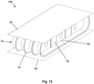
- FIGS 12-13 show a protection device 10b identical to the preceding protection device 10, and therefore with the same mattress body structure 16, including in addition, as well as the membrane inserts 40 interposed between adjacent side walls 18a, 18b, two opposite covering sheets 50 which form a covering cloak or coat, for example of the impermeable type, and further tie members 52 inserted inside respective slits in the covering sheets 50 and stably fixed there.
- the tie members 52 which have a strip-like form also have the function of stabilizing the flat form of the protection device 10b.
- the protection device preferably includes also a gas source (not shown) connected to the inflatable mattress body so as to inflate the mattress body 16 between the first deflated rest configuration and the second active inflated configuration.
- the gas source may be housed inside an inflatable element.
- the protection device 10 in order to perform inflation of the mattress body, in the event of a sudden fall and/or sliding and/or an impact involving a user or a vehicle being ridden/driven, the protection device 10 is designed to cooperate with special activation means (not shown) which are operationally connected for example to the gas source (as mentioned, not shown), such as a canister containing compressed cold gas, such as helium.
- the canister may be provided with a respective shut-off valve (not shown).
- the inflation fluid source may comprise gas generators of the pyrotechnic or hybrid type or other types known in the present state of the art.
- Opening of the shut-off valve of each inflation canister is preferably controlled by a control unit depending on the detection of the state of the vehicle/rider system; for example said control unit may implement a system for predicting the fall which allows early identification of the fall event and a reliable prediction of this event by means of accelerometer sensors fixed to the vehicle (or rider) and a unit for processing the signals produced by the said sensors.
- the device according to the present disclosure may also be applied using an activation cable connected to a vehicle ridden/driven by a user, which cable activates inflation of the inflatable element following the movement of the user away from the vehicle, for example following a fall or a sudden impact.
- an activation cable connected to a vehicle ridden/driven by a user, which cable activates inflation of the inflatable element following the movement of the user away from the vehicle, for example following a fall or a sudden impact.
- Use of a cable is employed in particular in the horse-riding sector.
- activation and inflation means may be integrated in the protection device according to the present invention or located on the outside thereof.
Landscapes
- Engineering & Computer Science (AREA)
- Health & Medical Sciences (AREA)
- General Health & Medical Sciences (AREA)
- Physical Education & Sports Medicine (AREA)
- Textile Engineering (AREA)
- Environmental & Geological Engineering (AREA)
- Mattresses And Other Support Structures For Chairs And Beds (AREA)
- Electrophotography Configuration And Component (AREA)
- Crystals, And After-Treatments Of Crystals (AREA)
- Developing Agents For Electrophotography (AREA)
- Professional, Industrial, Or Sporting Protective Garments (AREA)
Description
- The present disclosure relates in general to a personal protection device for protecting a user, wherein the device is preferably of the wearable type and/or type which can be associated with a wearable article, such as a garment, a jacket, a waistcoat or similar wearable article.
- It therefore consists of a protection device which preferably forms part of a wearable article, such as a garment or other article of clothing. The protection device includes in particular an inflatable body which, in the inflated condition, is configured to protect from impacts and/or falls a motorcycle rider or passenger or similar user, during a sporting activity and/or working activity and/or any other activity. Alternatively, the inflatable body is deigned to provide protection from the cold.
- A known protection device is, for example, one such as that described in the European patent
EP3291697B1 . Such a device includes an inflatable element designed to assume an active inflated condition and a deflated rest condition. The inflatable element includes a knitted body, namely a body made by means of a knitting process. Said knitted body is a closed or at least tubular structure defining an internal region or area or chamber. This internal chamber is occupied at least partially by a plurality of joining threads which connect together opposite portions of the knitted body. The fact of providing a single knitted body has the advantage of limiting the manufacturing waste and minimizing the production time; in fact, the joining threads and meshes may be processed using a single knitting machine. The joining threads form part of single thread connected to the opposite portions of the knitted body. In particular, the thread passes along alternate sections and continuously between a first portion and a second portion of the knitted body. - The inflatable element also includes impermeable walls which are arranged externally and allow the inflation fluid to be contained for a predetermined period of time. The walls consist, for example, of a first sheet, or first wall, and of a second sheet, or second wall, which are fixed together along respective perimetral edges. Said first and second sheets made of impermeable material cover and line on an outer side or external surface the knitted body.
- Such a wearable protection device is known from
EP2373189B1 . - Both wearable devices have the advantage that they have a flat mattress-like form in the inflated condition which is particularly suitable and appropriate for insertion in a garment. An inflatable element, thus made, while being very advantageous from many points of view, nevertheless has the drawback that it does not have a compact volume in the deflated condition and does not always allow suitable breathability in an article of clothing in which it is incorporated or inserted. In particular, the inflatable element in the deflated condition may create a kind of bag around the user's body which does not allow enough ventilation air to pass through.
- Another protection device is known from
CH 697 172 A5 claim 1. - One technical problem underlying the present disclosure consists in providing a protection device for protecting a user which is configured so that the inflatable body may maintain in the inflated condition a substantially mattress-like - and therefore substantially flat - form and at the same time may be able to overcome the drawbacks of the prior art and which allows a greater breathability and/or achieves further advantages.
- This problem is solved by a protection device for protecting a user and by a wearable article according to the respective independent claims. Secondary characteristic features forming the subject of the present disclosure are defined in the respective dependent claims.
- According to one aspect of the present disclosure, the personal protection device includes a mattress body including a plurality of inflatable elements arranged adjacent in sequence, wherein each inflatable element has an elongated envelope form, which is preferably substantially tubular, so as to define an internal chamber of the channel type, i.e. shaped like a channel.
- The mattress body is able to assume a first deflated rest configuration in which the inflatable elements are in a deflated condition arranged close to each other or stacked on top of each other. The mattress body is able to assume in addition a second active inflated configuration in which said inflatable elements in a second active inflated configuration. The shape of the mattress body which, as mentioned, is formed overall by a plurality of tubular elements arranged adjacent in sequence, favours unfolding from the first deflated rest configuration (stacked condition) into the second active inflated configuration where it is extended and unfolded.
- Each inflatable element has an elongated, preferably tubular, form and therefore the channel-shaped internal chamber, when the inflatable element is substantially inflated, has a shape corresponding to the internal empty volume of a tubular element. The tubular elements are in fact long and narrow independent bodies which are joined together in sequence, side-by-side. More particularly, they consist of inflatable elements which are linear or straight in the inflated condition, namely have a linear and/or straight form in the second inflated configuration, and are not curved.
- The term "linear and/or straight form" is understood as meaning a form which follows substantially a continuous straight line or straight linear trajectory, or which at least partly follows a straight continuous line or straight linear trajectory so that, overall, the aforementioned mattress body is obtained, namely a body which has a mattress-like form, namely a body which, overall in the second inflated configuration, has, an envelope shape in the form of an inflated panel or carpet which resembles the form of a low parallelepiped. The mattress body may be filled with a fluid, such as a gas, or a liquid.
- In this way, the tubular elements may easily pass from the first deflated rest configuration (stacked condition), where it is compact, into an extended/unfolded condition, in which the inflatable elements are fully expanded so as to obtain the mattress body with a flat form in an inflated panel configuration.
- The inflatable elements therefore have, viewed overall, adhering pairs of sides or side walls and two opposite sides or walls which, once the inflatable elements are joined together, form opposite external surfaces of the mattress body, namely a surface or wall which is exposed to an impact or to the cold and a rear wall facing the user.
- The two opposite surfaces are substantially flat in the second active inflated configuration.
- As a result, when the mattress body is in the second active inflated configuration, the adhering side walls of two adjacent inflatable elements act as tensioning components or tie members between the two external surfaces, so as to provide a way of controlling the mattress-like or flat form of the mattress body. When the inflatable mattress body is inflated, the mutually adhering side walls are preferably tensioned. In other words, it is the mutually adhering side walls of two adjacent inflatable elements which determine the flat form similar to a flat panel.
- The maximum tension of the side walls which act as tensioning components determines the maximum possible distance between the opposite external walls.
- The side walls may be adherent over their entire area, or only partially, along one edge.
- In particular, the above-described geometry of the parts enables a structure which is as flat as possible to be obtained, and the inflatable elements are arranged alongside each other and at the same time define, by means of the adherent side walls, internal separating walls or partitions which may be reinforced with reinforcing inserts and are suitably arranged so as to create a plurality of housings. The internal walls or partitions are parallel to each other so as to define a plurality of channels which are parallel to each other.
- Owing to the form control, the inflatable element may be easily combined with other protection devices or elements, for example rigid, plate-like protection bodies which are separate from the inflatable body and have a form matching that of the inflatable element in the second active inflated configuration or inserted in the pocket of the wearable articles.
- A further advantage consists in the fact that the adherent walls (which are completely adherent or only partially adherent) which act as tensioning components or tie members ensure a limited expansion of the inflatable element in an inflated condition so as to obtain a compact volume, and in particular a limited thickness, while at the same time ensuring suitable protection for the user.
- Since it in fact consists of an inflatable device, this solution is particularly advantageous, for a wearable article, such as a garment, a jacket, a suit or other article of clothing.
- This compact volume moreover helps ensure, in the event of accidental inflation of the inflatable element, less inconvenience or risk for user while he/she is driving/riding a vehicle. In other words, a limited expansion of the inflatable element does not adversely affect control of a vehicle by the user and therefore does not risk causing an accident.
- A further advantage consists in the fact, by controlling the form of the inflatable element, it is possible to control (and in particular limit) also the quantity of gas needed to inflate the inflatable element.
- The inflatable mattress body is therefore a flexible body which, in the second active inflated configuration, maintains this condition for a given period of time. Preferably it consist of a body which is impermeable to an inflation gas. In this case, in order to deflate the mattress body, a breather valve is provided.
- The mattress body may also be further lined with a further covering coat which allows the protection device to reach greater pressures in the second active inflated condition.
- More particularly, a body made of pressure-resistant material and able to ensure the gas-tightness for at least a certain period of time may be used as the material of the mattress body. Such a material may consist, for example, of membranes made of PU (polyurethane), EVA (ethylene vinyl acetate) or TPE (thermoplastic elastomer). These membranes may also be impregnated with non-extendable small meshes for a greater strength of the inflatable elements (in terms of resistance to expansion).
- Alternatively, the mattress body may be made of a breathable material, such as a mesh body or the like, which is in turn coated with a membrane, a sheet or other impermeable layer, acting as a covering coat.
- As mentioned, in order to create the mattress body, a wall of an inflatable element of the plurality of inflatable elements is fixed adheringly (completely or only locally, for example along one edge) to a wall of an adjacent inflatable element of the plurality of inflatable elements, so as to define an adherence zone between two adjacent inflatable elements.
- Even more particularly, each inflatable element includes at least two sheets which are joined together along a perimeter so as to define a perimetral joining edge. Owing to the above-described geometry of the parts, along the sequence of adjacent inflatable elements, namely along a direction of expansion of the mattress body or direction of juxtaposition, it can be understood that said adherence zone between two adjacent inflatable elements alternates with a perimetral joining edge of the two sheets of the same inflatable element. A mattress body, the structure of which is similar to that of a concertina or a bellows, is therefore formed.
- This configuration facilitates or guides an opening or closing movement of the mattress body between the first deflated rest configuration, in which the inflatable elements are in a deflated condition, arranged close to each other or stacked on top of each other, and the second active inflated configuration in which said inflatable elements are in a second active inflated configuration. In fact, at the moment of inflation, the expansion of the mattress body between the first deflated rest configuration and the second active inflated configuration reproduces the concertina-like movement. Consequently, the expansion may be properly controlled owing to this structure.
- Considered from another point of view, the mattress body is formed by a plurality of sheets with an elongated form, each of which in sequence is joined, for example by means of gluing, on one side adheringly, for example over all or nearly all the contact surface, to an adjacent sheet, and on the opposite side, for example by means of laser welding, only along the perimeter to an adjacent sheet so as to form the inflatable mattress body. Each elongated sheet is joined in a different way on the two faces or sides, namely is joined on one face only along the perimeter, and on the opposite face is joined over most of the surface.
- In other words, according to the present disclosure, each inflatable element is in fact a body of the double-leaf type, i.e. as though having two flat sheets which are joined along the perimeter and which form a long and narrow body. It can be understood that the geometrical form chosen, of an inflatable element with double leaf joined together along the perimetral edge, favours the compression of one wall against the other one in the first deflated rest configuration in a concertina-like manner, or at the same time opening towards the second active inflated configuration again like a concertina.
- In order to reinforce the function of tensioning components or tie members of the side walls of an inflatable element and the adjacent inflatable element, the protection device includes additional membrane inserts which are included between two adjacent walls and fixed by means of gluing between the two walls. Each membrane insert interposed between adjacent walls has a reinforcing function. The membrane insert may be made of corduroy fabric.
- The protection device includes preferably also one or more gas sources connected to the inflatable mattress body so as to inflate the mattress body between the first deflated rest configuration and the second active inflated configuration. The gas source may be housed inside the internal channel-like chamber of an inflatable element.
- Alternatively, for inflation purposes, the inflatable elements may each have independent access to one or more gas sources. Alternatively, the adjacent inflatable elements are in fluid communication with each other for combined inflation. For example, the mattress body includes through-holes or fluid communication holes in the adhering walls of the two said adjacent inflatable elements, so as to form the fluid communication.
- The mattress body may also be filled with water or other liquid in order to perform further protection functions.
- The protection device may be housed inside a receiving area of the garment or a portion of the garment. This portion is to be understood as being a portion of the garment which lines a part of the body, such as the torso (neck region, chest region, shoulder blade region, back and arms). The portion of the garment includes said layer and is made using a predefined textile technology designed to provide the garment with given characteristics, such as breathability, or has ventilation openings.
- In the continuation of the present disclosure, "wearable article" is understood as meaning any article, or portion thereof, which may be worn by a user, such as an article of clothing, a garment or other wearable accessory.
- Preferably, the wearable article, or a portion thereof, includes a protection device such as that described above and at least one layer defining a receiving area for the body of a user, namely intended to receive the user's body for a protection function, whether it be protection from impacts or protection from the cold or other function. The protection device is associated with said layer, on one side, which may be identified as the inner side of said layer, facing said receiving zone. The layer of the wearable article also has breathability properties or has at least one ventilation opening.
- The receiving area includes a first part and a second part open towards the first part, and the breathability property or ventilation opening is provided at least opposite or, is associated with, said second part of the receiving area so as to allow ventilation at least in said second part. In the first part of the receiving area and in the second part of the receiving area, the mattress body performs its protection function in the second active inflated configuration, while ventilation and breathability may be ensured when the mattress body is in the first deflated rest configuration.
- Basically, the second part of the receiving area is configured to receive the mattress body in the second, active, extended and inflated configuration, while it remains free to allow breathability when the mattress body is in the first deflated rest configuration.
- Expressed in yet other words, in the second active inflated configuration, the mattress body occupies both said first part of the receiving area and said second part of said receiving area, and preferably the whole of the second part of the receiving area. In the first deflated rest configuration, the mattress body occupies only the first part of the receiving area. Consequently, once housed in the garment, and the mattress body is in the first deflated rest configuration, the second part of the receiving area, which is normally devoid of mattress body, guarantees the breathability and ventilation of the garment.
- Further characteristic features, advantages and modes of use forming the subject of the present disclosure will become clear from the following detailed description of a number of preferred examples of embodiment thereof, provided by way of a nonlimiting example. It is nevertheless evident that each embodiment may have one or more of the advantages listed above; in any case it is nevertheless not necessary that each embodiment should have simultaneously all the advantages listed.
- Reference will be made to the figures of the attached drawings in which:
-
Figure 1 shows a schematic, partially transparent, top plan view of a protection device in the second active inflated configuration according to one embodiment of the present disclosure; -
Figure 2 shows a schematic cross-sectional view along the line II-II of the protection device according toFigure 1 ; -
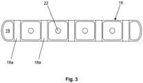
Figure 3 shows a schematic cross-sectional view along the line III-III of the protection device according toFigure 1 ; -
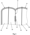
Figure 4 shows a detailed view of a partially cross-sectioned detail IV ofFigure 1 ; -
Figure 5 shows a schematic, partially transparent, view of a garment including a protection device according to the present disclosure in the first deflated rest configuration; -
Figure 6 shows a schematic, partially transparent, view of the garment inFigure 5 including a protection device according to the present disclosure in the second active inflated configuration; -
Figures 7 and 8 show, in schematic form, a protection device associated with a layer of a wearable article in the first deflated rest configuration and second active inflated configuration, respectively; -
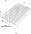
Figure 9 shows an axonometric view of a protection device according to a further embodiment of the present disclosure; -
Figure 10 shows an axonometric, partially cross-sectioned view of the protection device according toFigure 9 ; -
Figure 11 shows a partially transparent side view of the protection device according toFigure 9 ; -
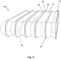
Figure 12 shows an exploded axonometric view of a protection device according to a further embodiment of the present disclosure; -
Figure 13 shows an axonometric, partially cross-sectioned view of the protection device according toFigure 12 . - With reference to the attached figures, the
reference number 100 indicates a wearable article, in the present case a waistcoat, including apersonal protection device Figures 1-8 ,9-11 and12-13 , respectively. These devices are substantially identical to each other and differ only in terms of the presence of inserts and the presence of a covering coat, formed for example by impermeable walls as indicated below. The description given below is applicable to all the embodiments. - A portion of the
wearable article 100, for example the chest portion, or a back portion, according to the present disclosure, includes at least onelayer 11 defining an area for accommodating the user's body. The layer is a layer of the waistcoat, or a lining of the waistcoat. Thelayer 11 is to be understood as being a layer of the waistcoat, in general, whether it is made of fabric or other material. Preferably, as will be explained more fully below, at least part of thelayer 11 ensures the breathability and allows the entry of air inside thewearable article 100. - In other words, the waistcoat or similar
wearable article 100 includes an area shown in broken lines and indicated by means of thereference number 12 which is intended to receive the body of a user for a protection function, whether it be protection from impacts, protection from the cold, or other function. The receivingarea 12 is, in the embodiment shown, an area intended to receive the torso of a user. - The
layer 11 also has, as mentioned, breathability properties or has at least oneventilation opening 15. Theprotection device layer 11, on an inner side of said layer towards said receiving area, as shown inFigures 7 and 8 . - More particularly, the
personal protection device mattress body 16, including a plurality ofinflatable elements 18, which are preferably identical to each other, arranged adjacent in sequence, wherein each inflatable element has the form of a long and narrow envelope, preferably tubular shaped, i.e. in the form of a closed tube, so as to each define aninternal chamber 19 shaped like a channel. Theinflatable elements 16 and the respectiveinternal chambers 19 are preferably in fluid communication by means of through-holes so as to form a single inflation chamber for saidinflatable elements 18. - Even more particularly, according to one aspect of the present disclosure, the
mattress body 16 is designed to assume a deflated rest configuration in which theinflatable elements 18 are in a deflated condition arranged close to each other or stacked on top of each other as shown inFigure 7 inside afirst part 12a of the receivingarea 12 underneath saidlayer 11, leaving free asecond part 12b of the receiving area which is open towards the first part. - The
mattress body 16 is also designed to assume a second active inflated configuration in which saidinflatable elements 18 are in an inflated condition and occupy both saidfirst part 12a of the receiving area and thesecond part 12b of said receivingarea 12. - Even more particularly, said at least one
layer 11 has said breathability property or saidventilation opening 15 at least in saidsecond part 12b of the receivingarea 12, and said second part of the receiving area, when themattress body 1 is in the first deflated rest configuration, is devoid of themattress body 16. Basically thesecond part 12b of the receivingarea 12 is configured to receive the protection device in the extended and inflated condition, while it remains free to allow breathability when theprotection device 10 is in the first deflated rest configuration. Themattress body 16, which overall is formed by a plurality oftubular elements 18 arranged adjacent in sequence, favours the unfolding from the stacked condition, into the extended and unfolded condition. As shown inFigure 8 , in the second active inflated configuration, the mattress body occupies preferably the whole of thesecond part 12b of the receiving area. - As mentioned, each
inflatable element 18 has a tubular shape and therefore theinternal chamber 19, when the inflatable element is substantially inflated, has a channel-like shape corresponding to the empty volume of a tubular element. Thetubular elements 18 are in fact narrow and long. As can be seen, they are elements which are straight and not curved; in this way, not only when they are extended, does themattress body 16 have a flat shape, but they may also pass easily from a compact stacked condition into an extended condition. - The
inflatable elements 18 therefore haveside walls opposite sides inflatable elements 18 are joined together in sequence or arranged side-by-side, form and act as opposite external surfaces, i.e. a surface or wall exposed to an impact or to the cold and a rear wall facing the user. As a result, when themattress element 16 is in the second active inflated configuration, theadjacent side walls mattress body 16 is inflated preferably so as to tension theside walls - In particular, the above-described geometry of the parts enables a structure which is as flat as possible to be obtained, and the
inflatable elements 18 are arranged alongside each other and at the same time define, by means of theadherent walls 18a, 1b, internal separating walls or partitions suitably arranged so as to create a plurality of housings. - Preferably, in order to achieve the fluid communication, the
mattress body 16 includes through-holes 22 or fluid communication holes in the adheringwalls - Preferably, in the embodiment shown each
inflatable element 18 is made of a material which is resistant to high pressure and designed to keep the entire mattress body inflated for a certain time period. - Alternatively, it can be understood that the
mattress body 16 may be covered by an impermeable sheet, namely an outer covering sheet which retains the fluid. - According to one aspect of the present disclosure, as shown in the detail of
Figure 4 , eachinflatable element 18 includes at least twosheets perimetral joining edge 30, defining for each inflatable element the aforementionedinternal chamber 19 in fluid communication with an adjacent internal chamber. Owing to the above-described geometry of the parts, along the sequence of adjacent inflatable elements, anadherence zone 31 alternates with aperimetral joining edge 30 of the twowalls inflatable element 18 is in fact therefore a body of the double-leaf type, i.e. as though having two flat sheets which are joined along the perimeter and which form a long and narrow body. It can be understood that the geometrical form chosen, of an inflatable element with double leaf joined together along theperimetral edge 30, favours the compression of one wall against the other one in the deflated condition or configuration in the manner of a concertina or bellows, or at the same time the opening, or unfolding, in said concertina manner, towards the inflated condition or configuration. - The joining together of the two walls or
sheets - With reference to
Figures 9-11 , aprotection device 10a identical to the precedingprotection device 10, and therefore with the samemattress body structure 16, is shown, but including in addition membrane inserts 40 interposed betweenadjacent side walls adjacent side walls adjacent side walls - With reference to
Figures 12-13 , these show aprotection device 10b identical to the precedingprotection device 10, and therefore with the samemattress body structure 16, including in addition, as well as the membrane inserts 40 interposed betweenadjacent side walls sheets 50 which form a covering cloak or coat, for example of the impermeable type, andfurther tie members 52 inserted inside respective slits in the coveringsheets 50 and stably fixed there. - The
tie members 52 which have a strip-like form also have the function of stabilizing the flat form of theprotection device 10b. - It is to be understood that the protection device preferably includes also a gas source (not shown) connected to the inflatable mattress body so as to inflate the
mattress body 16 between the first deflated rest configuration and the second active inflated configuration. The gas source may be housed inside an inflatable element. - In particular, with regard to inflation, in order to perform inflation of the mattress body, in the event of a sudden fall and/or sliding and/or an impact involving a user or a vehicle being ridden/driven, the
protection device 10 is designed to cooperate with special activation means (not shown) which are operationally connected for example to the gas source (as mentioned, not shown), such as a canister containing compressed cold gas, such as helium. The canister may be provided with a respective shut-off valve (not shown). - Alternatively, the inflation fluid source may comprise gas generators of the pyrotechnic or hybrid type or other types known in the present state of the art.
- Opening of the shut-off valve of each inflation canister is preferably controlled by a control unit depending on the detection of the state of the vehicle/rider system; for example said control unit may implement a system for predicting the fall which allows early identification of the fall event and a reliable prediction of this event by means of accelerometer sensors fixed to the vehicle (or rider) and a unit for processing the signals produced by the said sensors.
- Alternatively, the device according to the present disclosure may also be applied using an activation cable connected to a vehicle ridden/driven by a user, which cable activates inflation of the inflatable element following the movement of the user away from the vehicle, for example following a fall or a sudden impact. Use of a cable is employed in particular in the horse-riding sector.
- In any case the aforementioned activation and inflation means may be integrated in the protection device according to the present invention or located on the outside thereof.
- It should also be noted that the activation modes, although being an aspect of particular importance for effective operation of the device, will not be further described in greater detail since they are methods which are essentially already known to a person skilled in the art of protection of a person from sudden impacts.
- The subject-matter of the present disclosure has been described hitherto with reference to its embodiments. It is to be understood that other embodiments relating to the same inventive idea may exist, all of these falling within the scope of protection of the claims which are attached below.
Claims (14)
- Protection device (10, 10a, 10b) for the personal protection of a user, wherein said device includes a mattress body (16) including a plurality of inflatable elements (18), arranged adjacent and side-by-side in sequence, wherein each inflatable element (18) has an elongated envelope shape so as to define an internal chamber (19) shaped like a channel, and wherein the mattress body (16) is able to assume a first deflated rest configuration in which the inflatable elements (18) are in a deflated condition arranged close to each other or stacked on top of each other, and wherein the mattress body (16) is able to assume a second active inflated configuration, and wherein- said inflatable elements (18) have, in said second active inflated configuration, a linear and/or straight form;
the protection device is characterized in that- each of the inflatable elements (18) has at least one first side wall (18a, 18b) connected adheringly to a second side wall (18a, 18b) of an adjacent inflatable element so as to define at least one adherence zone (31), and- each of the inflatable elements (18) has two further opposite sides (18c, 18d), and- wherein in said sequence of inflatable elements (18) the opposite sides (18c, 18d) of the inflatable elements (18) define opposite external surfaces of the mattress body (16), wherein the opposite external surfaces include a surface or wall exposed to an impact or to the cold, and a rear wall facing the user, andwherein said adherence zone (31) between the first side wall (18a, 18b) of an inflatable element (18) and the second side wall (18a, 18b) of an adjacent inflatable element (18) acts as a tie member between the two opposite external surfaces so as to control a mattress-like form of the mattress body (16) in the second active inflated configuration, andwherein each of the inflatable elements (18) includes at least two sheets (28, 29) joined together along a perimeter so as to define a perimetral joining edge (30) and wherein, along, or in a direction of, said sequence of adjacent inflatable elements (18), each adherence zone between the first side wall (18a, 18b) of the inflatable element (18) and the second side wall (18a, 18b) of the adjacent inflatable element (18) alternates with a perimetral joining edge (30) of the two sheets (28, 29) of a same inflatable element (18) so as to define a concertina or bellows structure. - Protection device (10, 10a, 10b) according to claim 1, wherein the inflatable elements (18) are identical to each other.
- Protection device (10, 10a, 10b) according to claim 1 or 2, wherein the inflatable elements (18) and the respective internal chambers (19) are in fluid communication so as to form a single inflation chamber for said inflatable elements (18).
- Protection device (10, 10a, 10b) according to any one of the preceding claims, wherein the inflatable elements (18) are tubular elements.
- Protection device (10, 10a, 10b) according to any one of the preceding claims, wherein the inflatable elements (18) are made of an impermeable material and each chamber is a hollow chamber.
- Protection device (10, 10a, 10b) according to any one of the preceding claims, wherein the mattress body (16) includes through-holes (22) or fluid communication holes in the first side wall (18a, 18b) of an inflatable element of the inflatable elements and in the second side wall (18a, 18b) of the adjacent inflatable element so as to form the fluid communication.
- Protection device (10, 10a, 10b) according to any one of the preceding claims, wherein the set of inflatable elements (18) is covered by at least a covering coat (50).
- Protection device (10, 10a, 10b) according to any one of the preceding claims wherein said protection device is an impact protection device, and includes a pressurised gas source, said protection device being configured to assume said second active inflated configuration in the event of danger or impact.
- Protection device (10, 10a, 10b) according to any one of the preceding claims 1 to 7, wherein said protection device is a cold protection device, and includes a pressurised gas source, wherein said protection device in said second active inflated configuration is designed to protect a user from the cold.
- Protection device (10, 10a, 10b) according to any one of the preceding claims, including membrane inserts (40) fixed in an interposed position between the first side wall (18a, 18b) of an inflatable element (18) and the second side wall (18a, 18b) of the adjacent inflatable element.
- Protection device (10, 10a, 10b) according to any one of the preceding claims, in combination with claim 7, including inserts (40) with the function of tie members (52) fixed in an interposed position between the first side wall (18a, 18b) of an inflatable element and the second side wall (18a, 18b) of the adjacent inflatable element, said inserts with the function of tie members (52) being fixed to said covering coat (50).
- Protection device (10, 10a, 10b) according to any one of the preceding claims, wherein said device is a wearable device.
- Wearable article (100) such as a garment, including a protection device (10, 10a, 10b) according to any one of the preceding claims.
- Wearable article (100) according to the preceding claim, including at least one layer (11) defining at least partially a receiving area (12) for accommodating the body of a user, wherein the layer (11) has breathability properties and/or at least one ventilation opening (15) and wherein said protection device (10, 10a, 10b) is associated with said layer (11) on one side of said layer directed towards said receiving area (12), and wherein said receiving area (12) includes a first part (12a) and a second part (12b) open towards the first part (12a) and said breathability property and/or at least one ventilation opening (15) of the layer is provided at least in the region of said second part (12b); and wherein said inflatable elements occupy in the first deflated rest configuration said first part (12a) of the receiving area (12) below said layer (11) and in the second active inflated configuration they occupy said first part (12a) of the receiving area and said second part (12b) of said receiving area (12) and wherein a situation in which said second part (12b) of the receiving area (12) is devoid of the mattress body (16) corresponds to a situation in which the mattress body (16) is in said first deflated rest configuration.
Applications Claiming Priority (1)
| Application Number | Priority Date | Filing Date | Title |
|---|---|---|---|
| IT102021000031829A IT202100031829A1 (en) | 2021-12-20 | 2021-12-20 | PERSONAL PROTECTIVE EQUIPMENT |
Publications (3)
| Publication Number | Publication Date |
|---|---|
| EP4197378A1 EP4197378A1 (en) | 2023-06-21 |
| EP4197378C0 EP4197378C0 (en) | 2024-07-31 |
| EP4197378B1 true EP4197378B1 (en) | 2024-07-31 |
Family
ID=80625281
Family Applications (1)
| Application Number | Title | Priority Date | Filing Date |
|---|---|---|---|
| EP22214754.8A Active EP4197378B1 (en) | 2021-12-20 | 2022-12-19 | Personal protection device |
Country Status (3)
| Country | Link |
|---|---|
| EP (1) | EP4197378B1 (en) |
| ES (1) | ES2993591T3 (en) |
| IT (1) | IT202100031829A1 (en) |
Families Citing this family (3)
| Publication number | Priority date | Publication date | Assignee | Title |
|---|---|---|---|---|
| IT202200010424A1 (en) | 2022-05-19 | 2023-11-19 | D Air Lab S R L | PERSONAL PROTECTIVE EQUIPMENT |
| EP4640095A1 (en) * | 2024-04-23 | 2025-10-29 | D-Air Lab S.r.l. | Protection device and process of making the same |
| US20260033574A1 (en) * | 2024-07-31 | 2026-02-05 | Nike, Inc. | Laminates, Bladders, and Garments Including Laminates and Bladders |
Citations (6)
| Publication number | Priority date | Publication date | Assignee | Title |
|---|---|---|---|---|
| CH697172A5 (en) | 2004-06-04 | 2008-06-25 | Christian Koeppel Dr Med | Airbag for a piece of clothing comprises a body integrated into the piece of clothing and folds flat when not in use on the side of the body to be protected |
| US20100117039A1 (en) | 2008-09-09 | 2010-05-13 | Mangar International (Holdings) Ltd. | Inflatable structure for use in an inflatable lifting device and an inflatable lifting device incorporating two or more such structures |
| US20130088056A1 (en) | 2011-10-11 | 2013-04-11 | Zodiac Aerospace | Tubular airbag |
| EP3434123A1 (en) | 2017-07-25 | 2019-01-30 | Dainese S.p.A. | Protective device |
| EP3498117A1 (en) | 2017-12-18 | 2019-06-19 | Dainese S.p.A. | Garment for a user's protection comprising an inflatable member |
| GB2590811A (en) | 2020-12-23 | 2021-07-07 | Airhead Design Ltd | Inflatable helmet |
Family Cites Families (3)
| Publication number | Priority date | Publication date | Assignee | Title |
|---|---|---|---|---|
| EP1767108A1 (en) * | 2005-09-21 | 2007-03-28 | Hajdar Ademaj | Inflatable protective garment |
| JP5486607B2 (en) | 2008-12-09 | 2014-05-07 | ダイネーゼ ソシエタ ペル アチオーニ | Protection device including an inflatable member |
| ITVR20150074A1 (en) | 2015-05-06 | 2016-11-06 | Dainese Spa | PROTECTIVE DEVICE AND METHOD FOR REALIZING THIS PROTECTIVE DEVICE |
-
2021
- 2021-12-20 IT IT102021000031829A patent/IT202100031829A1/en unknown
-
2022
- 2022-12-19 ES ES22214754T patent/ES2993591T3/en active Active
- 2022-12-19 EP EP22214754.8A patent/EP4197378B1/en active Active
Patent Citations (6)
| Publication number | Priority date | Publication date | Assignee | Title |
|---|---|---|---|---|
| CH697172A5 (en) | 2004-06-04 | 2008-06-25 | Christian Koeppel Dr Med | Airbag for a piece of clothing comprises a body integrated into the piece of clothing and folds flat when not in use on the side of the body to be protected |
| US20100117039A1 (en) | 2008-09-09 | 2010-05-13 | Mangar International (Holdings) Ltd. | Inflatable structure for use in an inflatable lifting device and an inflatable lifting device incorporating two or more such structures |
| US20130088056A1 (en) | 2011-10-11 | 2013-04-11 | Zodiac Aerospace | Tubular airbag |
| EP3434123A1 (en) | 2017-07-25 | 2019-01-30 | Dainese S.p.A. | Protective device |
| EP3498117A1 (en) | 2017-12-18 | 2019-06-19 | Dainese S.p.A. | Garment for a user's protection comprising an inflatable member |
| GB2590811A (en) | 2020-12-23 | 2021-07-07 | Airhead Design Ltd | Inflatable helmet |
Also Published As
| Publication number | Publication date |
|---|---|
| ES2993591T3 (en) | 2025-01-02 |
| EP4197378C0 (en) | 2024-07-31 |
| EP4197378A1 (en) | 2023-06-21 |
| IT202100031829A1 (en) | 2023-06-20 |
Similar Documents
| Publication | Publication Date | Title |
|---|---|---|
| EP4197378B1 (en) | Personal protection device | |
| EP2373189B2 (en) | Personal protection device and garment including such a device | |
| US12012065B2 (en) | Protective device and method for making said protective device | |
| CN113194772B (en) | Wearable air bag device | |
| US5494469A (en) | Inflatable life vest | |
| US9869532B2 (en) | Maritime ballistic safety carrier | |
| EP3434123B1 (en) | Protective device | |
| JP2023531261A (en) | Wearable protection device | |
| AU2024202591A1 (en) | Survival systems | |
| WO2004105522A1 (en) | Protective garment, which is worn with shoulder pad having inflatable bladder, for firefighter or for emergency worker | |
| EP3835140B1 (en) | Protective device and method for manufaturing such protective device | |
| EP3287026B1 (en) | Personal protection device | |
| EP4278917B1 (en) | Personal protection device | |
| EP4159071B1 (en) | Protection device | |
| WO2023084098A1 (en) | Wearable airbag | |
| EP4424193A1 (en) | Protection device for the protection of a user |
Legal Events
| Date | Code | Title | Description |
|---|---|---|---|
| PUAI | Public reference made under article 153(3) epc to a published international application that has entered the european phase |
Free format text: ORIGINAL CODE: 0009012 |
|
| STAA | Information on the status of an ep patent application or granted ep patent |
Free format text: STATUS: THE APPLICATION HAS BEEN PUBLISHED |
|
| AK | Designated contracting states |
Kind code of ref document: A1 Designated state(s): AL AT BE BG CH CY CZ DE DK EE ES FI FR GB GR HR HU IE IS IT LI LT LU LV MC ME MK MT NL NO PL PT RO RS SE SI SK SM TR |
|
| STAA | Information on the status of an ep patent application or granted ep patent |
Free format text: STATUS: REQUEST FOR EXAMINATION WAS MADE |
|
| 17P | Request for examination filed |
Effective date: 20231218 |
|
| RBV | Designated contracting states (corrected) |
Designated state(s): AL AT BE BG CH CY CZ DE DK EE ES FI FR GB GR HR HU IE IS IT LI LT LU LV MC ME MK MT NL NO PL PT RO RS SE SI SK SM TR |
|
| GRAP | Despatch of communication of intention to grant a patent |
Free format text: ORIGINAL CODE: EPIDOSNIGR1 |
|
| STAA | Information on the status of an ep patent application or granted ep patent |
Free format text: STATUS: GRANT OF PATENT IS INTENDED |
|
| INTG | Intention to grant announced |
Effective date: 20240425 |
|
| GRAS | Grant fee paid |
Free format text: ORIGINAL CODE: EPIDOSNIGR3 |
|
| GRAA | (expected) grant |
Free format text: ORIGINAL CODE: 0009210 |
|
| STAA | Information on the status of an ep patent application or granted ep patent |
Free format text: STATUS: THE PATENT HAS BEEN GRANTED |
|
| AK | Designated contracting states |
Kind code of ref document: B1 Designated state(s): AL AT BE BG CH CY CZ DE DK EE ES FI FR GB GR HR HU IE IS IT LI LT LU LV MC ME MK MT NL NO PL PT RO RS SE SI SK SM TR |
|
| REG | Reference to a national code |
Ref country code: CH Ref legal event code: EP Ref country code: GB Ref legal event code: FG4D |
|
| REG | Reference to a national code |
Ref country code: DE Ref legal event code: R096 Ref document number: 602022004994 Country of ref document: DE |
|
| REG | Reference to a national code |
Ref country code: IE Ref legal event code: FG4D |
|
| U01 | Request for unitary effect filed |
Effective date: 20240826 |
|
| U07 | Unitary effect registered |
Designated state(s): AT BE BG DE DK EE FI FR IT LT LU LV MT NL PT RO SE SI Effective date: 20240904 |
|
| REG | Reference to a national code |
Ref country code: ES Ref legal event code: FG2A Ref document number: 2993591 Country of ref document: ES Kind code of ref document: T3 Effective date: 20250102 |
|
| PG25 | Lapsed in a contracting state [announced via postgrant information from national office to epo] |
Ref country code: NO Free format text: LAPSE BECAUSE OF FAILURE TO SUBMIT A TRANSLATION OF THE DESCRIPTION OR TO PAY THE FEE WITHIN THE PRESCRIBED TIME-LIMIT Effective date: 20241031 |
|
| PG25 | Lapsed in a contracting state [announced via postgrant information from national office to epo] |
Ref country code: GR Free format text: LAPSE BECAUSE OF FAILURE TO SUBMIT A TRANSLATION OF THE DESCRIPTION OR TO PAY THE FEE WITHIN THE PRESCRIBED TIME-LIMIT Effective date: 20241101 Ref country code: PL Free format text: LAPSE BECAUSE OF FAILURE TO SUBMIT A TRANSLATION OF THE DESCRIPTION OR TO PAY THE FEE WITHIN THE PRESCRIBED TIME-LIMIT Effective date: 20240731 |
|
| U20 | Renewal fee for the european patent with unitary effect paid |
Year of fee payment: 3 Effective date: 20241217 |
|
| PG25 | Lapsed in a contracting state [announced via postgrant information from national office to epo] |
Ref country code: IS Free format text: LAPSE BECAUSE OF FAILURE TO SUBMIT A TRANSLATION OF THE DESCRIPTION OR TO PAY THE FEE WITHIN THE PRESCRIBED TIME-LIMIT Effective date: 20241130 |
|
| PG25 | Lapsed in a contracting state [announced via postgrant information from national office to epo] |
Ref country code: HR Free format text: LAPSE BECAUSE OF FAILURE TO SUBMIT A TRANSLATION OF THE DESCRIPTION OR TO PAY THE FEE WITHIN THE PRESCRIBED TIME-LIMIT Effective date: 20240731 |
|
| PG25 | Lapsed in a contracting state [announced via postgrant information from national office to epo] |
Ref country code: RS Free format text: LAPSE BECAUSE OF FAILURE TO SUBMIT A TRANSLATION OF THE DESCRIPTION OR TO PAY THE FEE WITHIN THE PRESCRIBED TIME-LIMIT Effective date: 20241031 |
|
| PG25 | Lapsed in a contracting state [announced via postgrant information from national office to epo] |
Ref country code: RS Free format text: LAPSE BECAUSE OF FAILURE TO SUBMIT A TRANSLATION OF THE DESCRIPTION OR TO PAY THE FEE WITHIN THE PRESCRIBED TIME-LIMIT Effective date: 20241031 Ref country code: PL Free format text: LAPSE BECAUSE OF FAILURE TO SUBMIT A TRANSLATION OF THE DESCRIPTION OR TO PAY THE FEE WITHIN THE PRESCRIBED TIME-LIMIT Effective date: 20240731 Ref country code: NO Free format text: LAPSE BECAUSE OF FAILURE TO SUBMIT A TRANSLATION OF THE DESCRIPTION OR TO PAY THE FEE WITHIN THE PRESCRIBED TIME-LIMIT Effective date: 20241031 Ref country code: IS Free format text: LAPSE BECAUSE OF FAILURE TO SUBMIT A TRANSLATION OF THE DESCRIPTION OR TO PAY THE FEE WITHIN THE PRESCRIBED TIME-LIMIT Effective date: 20241130 Ref country code: HR Free format text: LAPSE BECAUSE OF FAILURE TO SUBMIT A TRANSLATION OF THE DESCRIPTION OR TO PAY THE FEE WITHIN THE PRESCRIBED TIME-LIMIT Effective date: 20240731 Ref country code: GR Free format text: LAPSE BECAUSE OF FAILURE TO SUBMIT A TRANSLATION OF THE DESCRIPTION OR TO PAY THE FEE WITHIN THE PRESCRIBED TIME-LIMIT Effective date: 20241101 |
|
| PG25 | Lapsed in a contracting state [announced via postgrant information from national office to epo] |
Ref country code: SM Free format text: LAPSE BECAUSE OF FAILURE TO SUBMIT A TRANSLATION OF THE DESCRIPTION OR TO PAY THE FEE WITHIN THE PRESCRIBED TIME-LIMIT Effective date: 20240731 |
|
| PGFP | Annual fee paid to national office [announced via postgrant information from national office to epo] |
Ref country code: ES Payment date: 20250131 Year of fee payment: 3 |
|
| PG25 | Lapsed in a contracting state [announced via postgrant information from national office to epo] |
Ref country code: CZ Free format text: LAPSE BECAUSE OF FAILURE TO SUBMIT A TRANSLATION OF THE DESCRIPTION OR TO PAY THE FEE WITHIN THE PRESCRIBED TIME-LIMIT Effective date: 20240731 |
|
| PG25 | Lapsed in a contracting state [announced via postgrant information from national office to epo] |
Ref country code: SK Free format text: LAPSE BECAUSE OF FAILURE TO SUBMIT A TRANSLATION OF THE DESCRIPTION OR TO PAY THE FEE WITHIN THE PRESCRIBED TIME-LIMIT Effective date: 20240731 |
|
| PLBI | Opposition filed |
Free format text: ORIGINAL CODE: 0009260 |
|
| PLAX | Notice of opposition and request to file observation + time limit sent |
Free format text: ORIGINAL CODE: EPIDOSNOBS2 |
|
| 26 | Opposition filed |
Opponent name: ALPINESTARS S.P.A. Effective date: 20250430 |
|
| PG25 | Lapsed in a contracting state [announced via postgrant information from national office to epo] |
Ref country code: MC Free format text: LAPSE BECAUSE OF FAILURE TO SUBMIT A TRANSLATION OF THE DESCRIPTION OR TO PAY THE FEE WITHIN THE PRESCRIBED TIME-LIMIT Effective date: 20240731 |
|
| PLBB | Reply of patent proprietor to notice(s) of opposition received |
Free format text: ORIGINAL CODE: EPIDOSNOBS3 |
|
| PG25 | Lapsed in a contracting state [announced via postgrant information from national office to epo] |
Ref country code: IE Free format text: LAPSE BECAUSE OF NON-PAYMENT OF DUE FEES Effective date: 20241219 |
|
| U1N | Appointed representative for the unitary patent procedure changed after the registration of the unitary effect |
Representative=s name: GIOPATO, PAOLO; IT |
|
| U20 | Renewal fee for the european patent with unitary effect paid |
Year of fee payment: 4 Effective date: 20251202 |