EP4196838B1 - Sensor housing, housing-integrated sensor- and cleaning-device and vehicle - Google Patents
Sensor housing, housing-integrated sensor- and cleaning-device and vehicle Download PDFInfo
- Publication number
- EP4196838B1 EP4196838B1 EP20758135.6A EP20758135A EP4196838B1 EP 4196838 B1 EP4196838 B1 EP 4196838B1 EP 20758135 A EP20758135 A EP 20758135A EP 4196838 B1 EP4196838 B1 EP 4196838B1
- Authority
- EP
- European Patent Office
- Prior art keywords
- sensor
- housing
- cleaning
- integrated
- washer
- Prior art date
- Legal status (The legal status is an assumption and is not a legal conclusion. Google has not performed a legal analysis and makes no representation as to the accuracy of the status listed.)
- Active
Links
Images



Classifications
-
- B—PERFORMING OPERATIONS; TRANSPORTING
- B60—VEHICLES IN GENERAL
- B60S—SERVICING, CLEANING, REPAIRING, SUPPORTING, LIFTING, OR MANOEUVRING OF VEHICLES, NOT OTHERWISE PROVIDED FOR
- B60S1/00—Cleaning of vehicles
- B60S1/02—Cleaning windscreens, windows or optical devices
- B60S1/46—Cleaning windscreens, windows or optical devices using liquid; Windscreen washers
- B60S1/48—Liquid supply therefor
- B60S1/52—Arrangement of nozzles; Liquid spreading means
-
- B—PERFORMING OPERATIONS; TRANSPORTING
- B60—VEHICLES IN GENERAL
- B60S—SERVICING, CLEANING, REPAIRING, SUPPORTING, LIFTING, OR MANOEUVRING OF VEHICLES, NOT OTHERWISE PROVIDED FOR
- B60S1/00—Cleaning of vehicles
- B60S1/02—Cleaning windscreens, windows or optical devices
- B60S1/46—Cleaning windscreens, windows or optical devices using liquid; Windscreen washers
- B60S1/48—Liquid supply therefor
- B60S1/52—Arrangement of nozzles; Liquid spreading means
- B60S1/522—Arrangement of nozzles; Liquid spreading means moving liquid spreading means, e.g. arranged in wiper arms
- B60S1/528—Arrangement of nozzles; Liquid spreading means moving liquid spreading means, e.g. arranged in wiper arms the spreading means being moved between a rest position and a working position
-
- B—PERFORMING OPERATIONS; TRANSPORTING
- B60—VEHICLES IN GENERAL
- B60S—SERVICING, CLEANING, REPAIRING, SUPPORTING, LIFTING, OR MANOEUVRING OF VEHICLES, NOT OTHERWISE PROVIDED FOR
- B60S1/00—Cleaning of vehicles
- B60S1/02—Cleaning windscreens, windows or optical devices
- B60S1/54—Cleaning windscreens, windows or optical devices using gas, e.g. hot air
-
- B—PERFORMING OPERATIONS; TRANSPORTING
- B60—VEHICLES IN GENERAL
- B60S—SERVICING, CLEANING, REPAIRING, SUPPORTING, LIFTING, OR MANOEUVRING OF VEHICLES, NOT OTHERWISE PROVIDED FOR
- B60S1/00—Cleaning of vehicles
- B60S1/02—Cleaning windscreens, windows or optical devices
- B60S1/56—Cleaning windscreens, windows or optical devices specially adapted for cleaning other parts or devices than front windows or windscreens
-
- G—PHYSICS
- G01—MEASURING; TESTING
- G01S—RADIO DIRECTION-FINDING; RADIO NAVIGATION; DETERMINING DISTANCE OR VELOCITY BY USE OF RADIO WAVES; LOCATING OR PRESENCE-DETECTING BY USE OF THE REFLECTION OR RERADIATION OF RADIO WAVES; ANALOGOUS ARRANGEMENTS USING OTHER WAVES
- G01S13/00—Systems using the reflection or reradiation of radio waves, e.g. radar systems; Analogous systems using reflection or reradiation of waves whose nature or wavelength is irrelevant or unspecified
- G01S13/86—Combinations of radar systems with non-radar systems, e.g. sonar, direction finder
- G01S13/865—Combination of radar systems with lidar systems
-
- G—PHYSICS
- G01—MEASURING; TESTING
- G01S—RADIO DIRECTION-FINDING; RADIO NAVIGATION; DETERMINING DISTANCE OR VELOCITY BY USE OF RADIO WAVES; LOCATING OR PRESENCE-DETECTING BY USE OF THE REFLECTION OR RERADIATION OF RADIO WAVES; ANALOGOUS ARRANGEMENTS USING OTHER WAVES
- G01S13/00—Systems using the reflection or reradiation of radio waves, e.g. radar systems; Analogous systems using reflection or reradiation of waves whose nature or wavelength is irrelevant or unspecified
- G01S13/86—Combinations of radar systems with non-radar systems, e.g. sonar, direction finder
- G01S13/867—Combination of radar systems with cameras
-
- G—PHYSICS
- G01—MEASURING; TESTING
- G01S—RADIO DIRECTION-FINDING; RADIO NAVIGATION; DETERMINING DISTANCE OR VELOCITY BY USE OF RADIO WAVES; LOCATING OR PRESENCE-DETECTING BY USE OF THE REFLECTION OR RERADIATION OF RADIO WAVES; ANALOGOUS ARRANGEMENTS USING OTHER WAVES
- G01S13/00—Systems using the reflection or reradiation of radio waves, e.g. radar systems; Analogous systems using reflection or reradiation of waves whose nature or wavelength is irrelevant or unspecified
- G01S13/88—Radar or analogous systems specially adapted for specific applications
- G01S13/93—Radar or analogous systems specially adapted for specific applications for anti-collision purposes
- G01S13/931—Radar or analogous systems specially adapted for specific applications for anti-collision purposes of land vehicles
-
- G—PHYSICS
- G01—MEASURING; TESTING
- G01S—RADIO DIRECTION-FINDING; RADIO NAVIGATION; DETERMINING DISTANCE OR VELOCITY BY USE OF RADIO WAVES; LOCATING OR PRESENCE-DETECTING BY USE OF THE REFLECTION OR RERADIATION OF RADIO WAVES; ANALOGOUS ARRANGEMENTS USING OTHER WAVES
- G01S7/00—Details of systems according to groups G01S13/00, G01S15/00, G01S17/00
- G01S7/02—Details of systems according to groups G01S13/00, G01S15/00, G01S17/00 of systems according to group G01S13/00
- G01S7/027—Constructional details of housings, e.g. form, type, material or ruggedness
-
- G—PHYSICS
- G01—MEASURING; TESTING
- G01S—RADIO DIRECTION-FINDING; RADIO NAVIGATION; DETERMINING DISTANCE OR VELOCITY BY USE OF RADIO WAVES; LOCATING OR PRESENCE-DETECTING BY USE OF THE REFLECTION OR RERADIATION OF RADIO WAVES; ANALOGOUS ARRANGEMENTS USING OTHER WAVES
- G01S7/00—Details of systems according to groups G01S13/00, G01S15/00, G01S17/00
- G01S7/02—Details of systems according to groups G01S13/00, G01S15/00, G01S17/00 of systems according to group G01S13/00
- G01S7/40—Means for monitoring or calibrating
- G01S7/4004—Means for monitoring or calibrating of parts of a radar system
- G01S7/4039—Means for monitoring or calibrating of parts of a radar system of sensor or antenna obstruction, e.g. dirt- or ice-coating
- G01S7/4043—Means for monitoring or calibrating of parts of a radar system of sensor or antenna obstruction, e.g. dirt- or ice-coating including means to prevent or remove the obstruction
-
- G—PHYSICS
- G01—MEASURING; TESTING
- G01S—RADIO DIRECTION-FINDING; RADIO NAVIGATION; DETERMINING DISTANCE OR VELOCITY BY USE OF RADIO WAVES; LOCATING OR PRESENCE-DETECTING BY USE OF THE REFLECTION OR RERADIATION OF RADIO WAVES; ANALOGOUS ARRANGEMENTS USING OTHER WAVES
- G01S7/00—Details of systems according to groups G01S13/00, G01S15/00, G01S17/00
- G01S7/48—Details of systems according to groups G01S13/00, G01S15/00, G01S17/00 of systems according to group G01S17/00
- G01S7/481—Constructional features, e.g. arrangements of optical elements
- G01S7/4811—Constructional features, e.g. arrangements of optical elements common to transmitter and receiver
- G01S7/4813—Housing arrangements
-
- G—PHYSICS
- G02—OPTICS
- G02B—OPTICAL ELEMENTS, SYSTEMS OR APPARATUS
- G02B27/00—Optical systems or apparatus not provided for by any of the groups G02B1/00 - G02B26/00, G02B30/00
- G02B27/0006—Optical systems or apparatus not provided for by any of the groups G02B1/00 - G02B26/00, G02B30/00 with means to keep optical surfaces clean, e.g. by preventing or removing dirt, stains, contamination, condensation
-
- B—PERFORMING OPERATIONS; TRANSPORTING
- B60—VEHICLES IN GENERAL
- B60S—SERVICING, CLEANING, REPAIRING, SUPPORTING, LIFTING, OR MANOEUVRING OF VEHICLES, NOT OTHERWISE PROVIDED FOR
- B60S1/00—Cleaning of vehicles
- B60S1/02—Cleaning windscreens, windows or optical devices
- B60S1/023—Cleaning windscreens, windows or optical devices including defroster or demisting means
-
- G—PHYSICS
- G01—MEASURING; TESTING
- G01S—RADIO DIRECTION-FINDING; RADIO NAVIGATION; DETERMINING DISTANCE OR VELOCITY BY USE OF RADIO WAVES; LOCATING OR PRESENCE-DETECTING BY USE OF THE REFLECTION OR RERADIATION OF RADIO WAVES; ANALOGOUS ARRANGEMENTS USING OTHER WAVES
- G01S7/00—Details of systems according to groups G01S13/00, G01S15/00, G01S17/00
- G01S7/48—Details of systems according to groups G01S13/00, G01S15/00, G01S17/00 of systems according to group G01S17/00
- G01S7/497—Means for monitoring or calibrating
- G01S2007/4975—Means for monitoring or calibrating of sensor obstruction by, e.g. dirt- or ice-coating, e.g. by reflection measurement on front-screen
- G01S2007/4977—Means for monitoring or calibrating of sensor obstruction by, e.g. dirt- or ice-coating, e.g. by reflection measurement on front-screen including means to prevent or remove the obstruction
-
- G—PHYSICS
- G01—MEASURING; TESTING
- G01S—RADIO DIRECTION-FINDING; RADIO NAVIGATION; DETERMINING DISTANCE OR VELOCITY BY USE OF RADIO WAVES; LOCATING OR PRESENCE-DETECTING BY USE OF THE REFLECTION OR RERADIATION OF RADIO WAVES; ANALOGOUS ARRANGEMENTS USING OTHER WAVES
- G01S7/00—Details of systems according to groups G01S13/00, G01S15/00, G01S17/00
- G01S7/52—Details of systems according to groups G01S13/00, G01S15/00, G01S17/00 of systems according to group G01S15/00
- G01S7/52004—Means for monitoring or calibrating
- G01S2007/52009—Means for monitoring or calibrating of sensor obstruction, e.g. dirt- or ice-coating
-
- G—PHYSICS
- G01—MEASURING; TESTING
- G01S—RADIO DIRECTION-FINDING; RADIO NAVIGATION; DETERMINING DISTANCE OR VELOCITY BY USE OF RADIO WAVES; LOCATING OR PRESENCE-DETECTING BY USE OF THE REFLECTION OR RERADIATION OF RADIO WAVES; ANALOGOUS ARRANGEMENTS USING OTHER WAVES
- G01S13/00—Systems using the reflection or reradiation of radio waves, e.g. radar systems; Analogous systems using reflection or reradiation of waves whose nature or wavelength is irrelevant or unspecified
- G01S13/88—Radar or analogous systems specially adapted for specific applications
- G01S13/93—Radar or analogous systems specially adapted for specific applications for anti-collision purposes
- G01S13/931—Radar or analogous systems specially adapted for specific applications for anti-collision purposes of land vehicles
- G01S2013/9327—Sensor installation details
-
- G—PHYSICS
- G01—MEASURING; TESTING
- G01S—RADIO DIRECTION-FINDING; RADIO NAVIGATION; DETERMINING DISTANCE OR VELOCITY BY USE OF RADIO WAVES; LOCATING OR PRESENCE-DETECTING BY USE OF THE REFLECTION OR RERADIATION OF RADIO WAVES; ANALOGOUS ARRANGEMENTS USING OTHER WAVES
- G01S7/00—Details of systems according to groups G01S13/00, G01S15/00, G01S17/00
- G01S7/52—Details of systems according to groups G01S13/00, G01S15/00, G01S17/00 of systems according to group G01S15/00
- G01S7/521—Constructional features
Definitions
- the invention relates to a sensor housing of the preamble part of claim 1, for being assembled to a vehicle, wherein the sensor housing is further adapted to house at least one sensor for monitoring environmental conditions of the vehicle.
- the invention further relates to a device with said sensor housing connectable to a sensor.
- Vehicles in particular commercial vehicles --like the one described in US 5,574,426 or US2005/0104322 A1 -- have an increasingly high demand of sensoring functions for monitoring environmental conditions of the vehicle.
- the sensors as such are necessarily exposed to the ambient environment for monitoring purpose and thus, necessarily, are also exposed to impacts from the environment of various kind. These can be detrimental to the sensor functioning as such.
- the sensor is subject to deposition of debris like particles of dirt or particles resolved from liquid solutions, which are dried or baked on a sensor surface depending on the surrounding and kind of the environmental exposure of the vehicle.
- WO 2018/231070 discloses a housing-integrated sensor- and cleaning-device according to the preamble of claim 1.
- WO2009/112066 A1 of the applicant relates to a device for arranging environment sensors in a vehicle, by which objects in the vehicle environment can be detected, wherein at least one first and a second environment sensor are disposed in a common housing.
- the common housing relates to a housing as mentioned in the introduction.
- the environment sensors are disposed such that a first centerline of the detection range of the first environment sensor points in a different direction than a second centerline of the detection range of the second environment sensor. In a sense, thereby two cooperating sensors of the same kind are adapted to increase a monitoring area of detection without increasing mounting and cabling effort for the two cooperating sensors.
- ADAS Automated Driver Assistance Systems
- AD automated, autonomous or semi-autonomous driving
- sensors of different kind are not only related to a visual monitoring by a camera but also include sensors of a RADAR, LiDAR or a camera system or the like.
- sensors of different kind are not only related to a visual monitoring by a camera but also include sensors of a RADAR, LiDAR or a camera system or the like.
- sensors of different kind are not only related to a visual monitoring by a camera but also include sensors of a RADAR, LiDAR or a camera system or the like.
- Even for such complex sensor systems the need of a high level of sensoring finesse remains and thus the demand for keeping a sensor clean, in particular the sensor surface as window to the environment is to be kept as clean and as steadily clean as possible.
- the invention comes in the object thereof is to propose a useful sensor housing for being assembled to a vehicle wherein the sensor housing is further adapted to house at least one sensor for monitoring environmental conditions of the vehicle.
- a further object is to provide a housing-integrated sensor- and cleaning-device and vehicle of improved kind wherein the sensor housing also is adapted such that a cleaning of the sensor is possible in an improved way.
- a sensor housing of claim 1 This is a sensor housing as mentioned in the introduction is provided in that the sensor housing is adapted for being assembled to a vehicle, wherein the sensor housing is further adapted to house at least one sensor for monitoring environmental conditions of the vehicle. Therein a sensor adapter is resided in the housing to hold the at least one sensor.
- the sensor housing according to the invention is provided in that the adapter has a number of one or more assembly-fittings to hold the at least one sensor in monitoring position, and
- the invention is starting from the consideration that a sensor housing to house at least one sensor for monitoring environmental conditions should be subject to hold one or more sensor of the mentioned kind regardless of the kind of sensor or form of sensor.
- the invention has recognized that it is useful to in effect provide a scalable sensor housing, this is in particular a scalable single-sensor housing or multi-sensor housing, which is afforded according to the invention by a sensor adapter having a number of one or more assembly fittings to hold the at least one sensor, this is one or more sensors, in monitoring position.
- the adapter assembly fittings thus can be constituted of one or more of single or plural assembly fittings to each hold various kinds or forms of sensors; the assembly fittings can be all of same kind to hold a plurality of identical sensors side by side or in another preferable arrangement. More particularly the number of one or more assembly-fittings are adapted to hold a multitude of sensors, namely a multitude of sensors of the same kind or a multitude of sensors of different kind.
- the adapter in the sensor housing afford that the housing has a kind of scalability to host different sensors from different manufactures in combination or a plurality of sensors of same manufactures or; as the adapter is detachable the adapter can be replaced or exchanged by other adapters on demand - in effect thus, the same sensor housing can be used with various kinds of adapters for various kinds or numbers of a sensors.
- the invention provides a scalable sensor housing with integrated cleaning system; the sensor housing is scalable by means of the sensor adapter and further the placeholder as described below.
- a sensor adapter can also be formed as an adjustable disposition of the sensors inside housing in different monitoring positions like angles and/or placements.
- a placeholder should be integrated with the housing to hold a washer-body of a cleaning-device in position as to afford cleaning of the at least one sensor.
- the placeholder integrated with the housing is at best a true part of the housing like for instance integrated with the housing's casing like a casing wall or the like carrier wall to hold a washer-body suitable to be used for one or all or at least a useful number of sensors in the sensor housing.
- the number of washer-bodies on the placeholder integrated with the housing can be the same or more or preferably a lower number as compared to the number of sensors. Further, by integrating the placeholder to the housing this feature allows a fixing safe connection of the washer-body with the housing in an integrated solution.
- a connector means is integrated with the housing; this law to connect all plug and connections to on a one and the sensor and the washer-body to afford sufficient functioning thereof.
- a single plug and connection assembly is provided to connect the housing-integrated sensor- and cleaning-device to a vehicle.
- the sensor housing as an example a scalable single and multi-sensor housing-- can be used for a housing-integrated sensor- and cleaning-device wherein a combination of two or more sensors combined in a single-sensor housing is provided with at least one washer-body.
- the solution includes at least an insofar integrated washer-body or even a completely integrated cleaning system enabling plug and play solution through fast water/air pipe and cable connection.
- the sensor housing of the housing-integrated sensor- and cleaning-device protects the sensors, enables the plug and play installation and keeps sensors available in all conditions by keep it cleaned against debris of dirt and detrimental liquid solutions.
- Scalability of the sensor housing can also be implemented by one or more internal housing adapters, which e.g. can be used to host different sensors from different manufacturers in combination; meaning on demand two or more sensors in a sensor housing. Further the adapters can be used not only to integrate different types of sensors but also different or same types of sensors but with different geometries and fixation to a standard housing format. E.g. a sensor housing, respectively an adapter can be used to define on demand various different sensor angles for a sensor according to the use case.
- the connector means is integrated with the housing.
- the placeholder and/or connector means is part of the housing wall.
- the connector means comprising
- the washer-body is integrated with the sensor housing on the placeholder. Integrated nozzles allow the existing vehicle cleaning system to be easily integrated with the housing.
- an electronic interface plug and/or a supply-connection plug is integrated with the housing
- the sensor adapter 12 has an assembly fitting to variably hold different kind of sensors like a LiDAR sensor 200 and RADAR 300 - this is detachable and thus replaceable or exchangeable and different forms of sensors 200, 300, namely for instance a single LiDAR or a single RADAR sensor can be held on demand.
- the fixed sensor adapters 11, 12 as described is a kind of interface by means of the one or more assembly fittings to be used for multiple sensors independent of the sensor type and manufacturer.
- the washer-body 400 and the connector means 500 are placed on the outside of said walls 21, 22.
- the heater element 600 is integrated in said casing front-wall 21 of the casing.
- the casing front-wall 21 establishes a carrier wall of the casing 20 to hold said adapter 10 for the sensor 100, 200 and to integrate the heater element 600 and further to integrate the placeholder 14 for the washer-body 400.
- a resistance can be installed in the housing surface for heating-up the surface against concentration of snow or ice or just to dry the inner part of the housing. Resistance can be either a conductive surface printing or micro-wires embodied in plastic.
- the casing 20 with the casing walls 21, 22, 23, 24 of the housings 1100, 1200, 1201, 1101 and also of the housings 1300, 1400 is preferably composed of an omniphobic material/coating that repels dust and any type of contamination.
- said omniphobic material/coating incorporates said heating element 600 to melt snow and prevent ice buildup.
- the washer-body 400 has a washer-nozzle and a washer-body and as such is integrated at least with the nozzle to the housing, more particularly to the casing 20 enables a kind of "plug & play"-connection of fluid, or preferably pressurized airfluid from an air cleaning system.
- FIG.4 The arrangements of embodiments as shown in FIG.3 and described therewith can be subject to variants as some of these are shown in FIG.4 .
- the washer-body 400 in embodiment variants 1100, 1200 of the sensor housing can be placed with a placeholder at the casing front-wall 21 outside of the housing 1100, 1200.
- the washer-body 400 can be placed inside the housing; this is said placeholder 40 can be established at the inner side of the casing back-wall 22 to hold said washer-body.
- the above-mentioned sensor and connector means 500 can be established.
- This variant of straight-view single-sensor housings 1101, 1201 has the advantage that the sensor and connector means 500 are protected from the outer environment and also, the washer-body 400 is in direct neighborhood to the sensor 100, 200, 300 and consequently has direct effect in cleaning said sensor.
- FIG.5 shows an embodiment of a straight-view multi-sensor housing 1300 with a single or multitude of camera sensors 100 for being assembled with a housing-integrated sensor- and cleaning-device 3 to a vehicle V like a PKW, this is a vehicle V of FIG.1 or a commercial vehicle CV as described with FIG.2 or FIG.8 in particular.
- the sensor housing 1300 is in direct development of the aforementioned straight-view sensor housing 1201 with the addition that the sensor housing 1300 is adapted to house a multitude of sensors for monitoring environmental conditions of the vehicle V, CV.
- the variant of sensor housing 1300 again provides an adapter 10 resided in the housing to hold a camera sensor 100 and further adapters 10 (not shown in detail) are set aside therefrom to hold a LiDAR and/or RADAR sensor 200, 300 on demand and as preferred for use.
- the adapters 10 also of this multi-sensor housing for straight-view has a number of in this case three assembly fittings to hold the sensors 100, 200, 300 as shown in monitoring position.
- the variant of sensor housing 1300 similar to the variant of sensor housing 1201 holds the sensors 100, 200, 300 in a way such that the sensing direction is vertical to the casing front-wall 21 and casing back-wall 22 of the casing 20.
- the multi-sensor housing 1300 holds the sensors 100, 200, 300 in a straight view vertical to the front-end back-wall 21, 22 as described above.
- a placeholder is integrated into the back-wall 22 of the housing to hold a multitude of washer-bodies 401, 402, 403 in position to effort cleaning the sensors 100, 200, 300.
- the placeholder indicated by reference sign 40 is adapted to hold all of the washer-bodies 401, 402, 403 and is integrated into the casing back-wall 22 of the casing.
- each of the washer-bodies 401, 402, 403 respectively is assigned to each of the sensors 100, 200, 300 respectively; thus, for each sensor exactly one washer-body 401, 402, 403 is provided respectively.
- the multi-sensor straight-view sensor housing 1300 features a sensor and connector means 500 as described before with a sensor-connector 510 and a washer-connector 520 in the same manner as described before; this is, the sensor and connector means 500 is integrated into the housing at the inner side of the casing front-wall 21 and further adapted to connect all of the sensors 100, 200, 300 in the sensor housing 1300.
- FIG.6 shows another qualitatively different kind of multi-sensor housing 1400 with a single or multitude of camera sensors 100 of a housing-integrated sensor- and cleaning-device 4 wherein for features of the same kind or same function, the same reference marks are used for simplicity; respectively, the above-mentioned description also applies to the further embodiment of multi-sensor housing 1400.
- FIG.6 shows variants of an angular-view multi-sensor housing 1400, 1401, 1402 - they have in common that the variants of angular-view sensor housing 1400, 1401, 1402 are adapted to house multiple sensors 100, 200, 300 for monitoring environmental conditions of a vehicle CV, V. All of these variants can also provide a position for a multitude of camera sensors 100 to allow an increased coverage of a view angle angular field to the environment, preferably to allow an increased coverage of an angular field of near 120°or up to 180° or an even larger angular field for the view angle to the environment.
- a sensor view angle in all cases is not perpendicular to a casing front-wall 21 and a casing back-wall 22 but in an angle thereto in a trapezoidal casing 20; thus --as can be seen from FIG.2 -- once the respective housing-integrated sensor- and cleaning-device 4A, 4B is assembled to the vehicle the view angle of monitoring is not perpendicular but in an acute angle to a main plane of vehicle surface in angular view.
- the multi-sensor housing 1400 can be adapted so as to provide an angular view of at least part of the sensors for monitoring environmental conditions of a vehicle, this is, the respective monitoring angle of the LiDAR and/or RADAR sensor 200, 300 placed therein, can be varied in a predefined form or they are variable. E.g., also the angular view can be varied by actuating the adapter when respective actuators are also provided in the housing in a transient way. This is an acute angle different from the wall direction can be set on demand, which will be described further below.
- the casing 20 of the angular view multi-sensor housing 1400 has two casing side-walls 23, 24 and a casing back-wall 22 with connector means 500 as described before, for instance with sensor housings 1100, 1200.
- the casing front-wall 21 in this case of sensor housing 1400 is enlarged and provides a wide inner space of the trapezoidal sensor housing 1400.
- the front side 21 provides a sensor adapter 11 for the camera sensor 100 and this, in combination with a LiDAR sensor 200 plus the outside casing front-wall 21 placeholder for the washer-body 401 of a cleaning-device in position as to afford cleaning of the camera sensor 100 and the LiDAR sensor 200.
- the casing front-wall 21 functions as a carrier wall to hold the sensor adapter 11 and to integrate the placeholder and to integrate a heater element 600 as described before with, for instance, a sensor housing 1100, 1200.
- the trapezoidal casing 20 provides a left side angular casing front-wall 25 and a right side angular casing front-wall 26 in direct connection between casing front-wall 21 and casing side-walls 23, 24, wherein each of the angular casing front-walls 25, 26 also again features to hold a sensor adapter 15, 16.
- FIG.7 shows in more detail in view (A) of FIG.7 for the left side part of the casing.
- This is the left side angular casing front-wall 25 again is used as a carrier wall for holding a sensor adapter 15 to hold a RADAR sensor 300, wherein here, this sensor adapter 15 has an assembly fitting to hold the RADAR sensor 300 in monitoring position.
- the monitoring position is plain with the angular casing front-wall 25 and thus allows an angular supervision of the environmental condition of the vehicle; the angle is set by the angle between angular casing front-wall 25 and back casing sidewall 22.
- the left side angular casing front-wall 25 is used as a carrier wall for holding a sensor adapter 13 integrating a heater element 600 and integrating a placeholder 40 for the washer-body 402.
- the angular casing front-wall 25 of the angular view multi-sensor housing 1400 allows for the RADAR sensor 300 to be adapted in a monitoring angle between a large angle ⁇ to a lower monitoring angle ⁇ . It can be adapted even such that the RADAR sensor 300 could be used for straight view, when the adapting angle ⁇ is set large enough to put the RADAR sensor 300 in parallel position to the casing back-wall 22 of the casing 20. Corresponding measures are possible for a LiDAR sensor 200 instead of a RADAR sensor and also for any other kind of sensor like a camera sensor 100 instead.
- FIG.8 shows in view (A) a preferred fourth embodiment of a sensor housing 1500 for a further kind of a housing-integrated sensor- and cleaning-device 5 for a commercial vehicle CV at exemplary positions indicated by arrows in view (A) of FIG.8 .
- Exemplary positions indicate install positions at the vehicle, which favor integrated high-level ADAS solutions like smart corner monitors etc..
- the sensor housing 1500 is realized as a kind of head light sensor housing according to the concept of the invention.
- the sensor housing 1500 can establish in addition to a standard headlamp function (not shown) an additional auxiliary head lamp function.
Landscapes
- Engineering & Computer Science (AREA)
- Remote Sensing (AREA)
- Radar, Positioning & Navigation (AREA)
- Physics & Mathematics (AREA)
- General Physics & Mathematics (AREA)
- Computer Networks & Wireless Communication (AREA)
- Mechanical Engineering (AREA)
- Electromagnetism (AREA)
- Water Supply & Treatment (AREA)
- Optics & Photonics (AREA)
- Geophysics And Detection Of Objects (AREA)
- Cleaning In General (AREA)
- Studio Devices (AREA)
Description
- The invention relates to a sensor housing of the preamble part of claim 1, for being assembled to a vehicle, wherein the sensor housing is further adapted to house at least one sensor for monitoring environmental conditions of the vehicle. The invention further relates to a device with said sensor housing connectable to a sensor.
- Vehicles, in particular commercial vehicles --like the one described in
US 5,574,426 orUS2005/0104322 A1 -- have an increasingly high demand of sensoring functions for monitoring environmental conditions of the vehicle. The sensors as such are necessarily exposed to the ambient environment for monitoring purpose and thus, necessarily, are also exposed to impacts from the environment of various kind. These can be detrimental to the sensor functioning as such. Even in normal use, the sensor is subject to deposition of debris like particles of dirt or particles resolved from liquid solutions, which are dried or baked on a sensor surface depending on the surrounding and kind of the environmental exposure of the vehicle. -
WO 2018/231070 discloses a housing-integrated sensor- and cleaning-device according to the preamble of claim 1. - Further
WO2009/112066 A1 of the applicant relates to a device for arranging environment sensors in a vehicle, by which objects in the vehicle environment can be detected, wherein at least one first and a second environment sensor are disposed in a common housing. The common housing relates to a housing as mentioned in the introduction. The environment sensors are disposed such that a first centerline of the detection range of the first environment sensor points in a different direction than a second centerline of the detection range of the second environment sensor. In a sense, thereby two cooperating sensors of the same kind are adapted to increase a monitoring area of detection without increasing mounting and cabling effort for the two cooperating sensors. - On the other hand, vehicles increasingly take advantage from automated driver assisted systems - these are known as ADAS (Automated Driver Assistance Systems) for automated, autonomous or semi-autonomous driving (AD). The requirements thereof demand for sensors of different kind and purpose and safe availability thereof during function; sensors of different kind are not only related to a visual monitoring by a camera but also include sensors of a RADAR, LiDAR or a camera system or the like. Even for such complex sensor systems the need of a high level of sensoring finesse remains and thus the demand for keeping a sensor clean, in particular the sensor surface as window to the environment is to be kept as clean and as steadily clean as possible.
- Whereas a complete protection of the sensor as such is for the above reasons neither possible nor advised the strategy of regular and automatic cleaning of a sensor surface at least has become available in automated servicing of the sensors for upholding a correct and up to demand sensor functioning.
- In view of the increasing number of sensors, it has become problematic however that the periphery of cleaning-devices has at least partly become unshaped or bulk and the sensors as such are exposed to the environment unprotected. It is a demand to capture sensoring in an appropriate way while still the sensor is available for automated cleaning.
- This is where the invention comes in the object thereof is to propose a useful sensor housing for being assembled to a vehicle wherein the sensor housing is further adapted to house at least one sensor for monitoring environmental conditions of the vehicle. A further object is to provide a housing-integrated sensor- and cleaning-device and vehicle of improved kind wherein the sensor housing also is adapted such that a cleaning of the sensor is possible in an improved way.
- In particular, it is a further object of the invention to provide such sensor housing in a way to be available regardless of a special kind of sensor of cleaning demand thereof.
- The object is achieved by a sensor housing of claim 1. This is a sensor housing as mentioned in the introduction is provided in that the sensor housing is adapted for being assembled to a vehicle, wherein the sensor housing is further adapted to house at least one sensor for monitoring environmental conditions of the vehicle. Therein a sensor adapter is resided in the housing to hold the at least one sensor. The sensor housing according to the invention is provided in that
the adapter has a number of one or more assembly-fittings to hold the at least one sensor in monitoring position, and - a placeholder is integrated with the housing to hold a washer-body of a cleaning-device in position as to afford cleaning of the at least one sensor.
- The invention is starting from the consideration that a sensor housing to house at least one sensor for monitoring environmental conditions should be subject to hold one or more sensor of the mentioned kind regardless of the kind of sensor or form of sensor. The invention has recognized that it is useful to in effect provide a scalable sensor housing, this is in particular a scalable single-sensor housing or multi-sensor housing, which is afforded according to the invention by a sensor adapter having a number of one or more assembly fittings to hold the at least one sensor, this is one or more sensors, in monitoring position.
- The adapter assembly fittings thus can be constituted of one or more of single or plural assembly fittings to each hold various kinds or forms of sensors; the assembly fittings can be all of same kind to hold a plurality of identical sensors side by side or in another preferable arrangement. More particularly the number of one or more assembly-fittings are adapted to hold a multitude of sensors, namely a multitude of sensors of the same kind or a multitude of sensors of different kind.
- Thus, the adapter in the sensor housing afford that the housing has a kind of scalability to host different sensors from different manufactures in combination or a plurality of sensors of same manufactures or; as the adapter is detachable the adapter can be replaced or exchanged by other adapters on demand - in effect thus, the same sensor housing can be used with various kinds of adapters for various kinds or numbers of a sensors. In short terms, thus the invention provides a scalable sensor housing with integrated cleaning system; the sensor housing is scalable by means of the sensor adapter and further the placeholder as described below. A sensor adapter can also be formed as an adjustable disposition of the sensors inside housing in different monitoring positions like angles and/or placements.
- Further, the invention has recognized, that depending on the kind and number of sensors a placeholder should be integrated with the housing to hold a washer-body of a cleaning-device in position as to afford cleaning of the at least one sensor.
- The placeholder integrated with the housing is at best a true part of the housing like for instance integrated with the housing's casing like a casing wall or the like carrier wall to hold a washer-body suitable to be used for one or all or at least a useful number of sensors in the sensor housing.
- Thus, the number of washer-bodies on the placeholder integrated with the housing can be the same or more or preferably a lower number as compared to the number of sensors. Further, by integrating the placeholder to the housing this feature allows a fixing safe connection of the washer-body with the housing in an integrated solution.
- Further according to the invention a connector means is integrated with the housing; this law to connect all plug and connections to on a one and the sensor and the washer-body to afford sufficient functioning thereof. Preferably, only a single plug and connection assembly is provided to connect the housing-integrated sensor- and cleaning-device to a vehicle.
- In essence, thereby a plug and play installation is provided with the sensor housing for correct functioning of the sensor and the washer-body to clean the sensor.
- In particular, the sensor housing --as an example a scalable single and multi-sensor housing-- can be used for a housing-integrated sensor- and cleaning-device wherein a combination of two or more sensors combined in a single-sensor housing is provided with at least one washer-body. The solution includes at least an insofar integrated washer-body or even a completely integrated cleaning system enabling plug and play solution through fast water/air pipe and cable connection.
- The sensor housing of the housing-integrated sensor- and cleaning-device protects the sensors, enables the plug and play installation and keeps sensors available in all conditions by keep it cleaned against debris of dirt and detrimental liquid solutions.
- Scalability of the sensor housing can also be implemented by one or more internal housing adapters, which e.g. can be used to host different sensors from different manufacturers in combination; meaning on demand two or more sensors in a sensor housing. Further the adapters can be used not only to integrate different types of sensors but also different or same types of sensors but with different geometries and fixation to a standard housing format. E.g. a sensor housing, respectively an adapter can be used to define on demand various different sensor angles for a sensor according to the use case.
- These and further developed configurations of the invention are further outlined in the dependent claims. The dependent claims provide further developments with regard to associated technical advantages. Thereby, the mentioned advantages of the proposed concept are even more improved. For each feature of the dependent claims, it is claimed independent protection independent from all other features of this disclosure.
- Preferably, the connector means is integrated with the housing. In a particular preferred development, the placeholder and/or connector means is part of the housing wall.
- In a particular preferred development, the connector means comprising
- an electronic interface to connect the sensor to a data- and/or energy-supply of the vehicle and
- a connection fitting to connect the washer-body to the cleaning-device. Preferably there is only one connector as interface to the vehicle, making final assembly easier (plug and play concept). Still also, there can be a single or multiple connections for cleaning system depending on the need. Single connection enables a single profile of cleaning to all sensors at the same time. Multiple connections enable an independent cleaning profile to each sensor.
- In a particular preferred development, the washer-body is integrated with the sensor housing on the placeholder. Integrated nozzles allow the existing vehicle cleaning system to be easily integrated with the housing.
- In a particular preferred development an electronic interface plug and/or a supply-connection plug is integrated with the housing
- In a particular preferred development the sensor adapter is resided at an inner side of the housing wall vis-à-vis the placeholder.
- In a particular preferred development the sensor housing has a carrier-wall wherein the placeholder is resided on an outer side thereof and the sensor adapter is resided on an inner side thereof vis-à-vis, in particular wherein the carrier wall is adapted to hold on an outer side the placeholder and on an inner side the sensor adapter.
- In a particular preferred development, the housing holds a heater element and/or the heater element is integrated in a housing wall, in particular in the carrier-wall. Generally, the housing surface is composed of an omniphobic material/coating that repels dust and any type of contamination. Optionally, the surface incorporates a Heating element to melt snow and prevent ice buildup.
- In a particular preferred development, the connector means is placed in the housing away from the carrier-wall.
- In a particular preferred development sensor adapter and/or the carrier wall provides an adjustment means for tuning a sensor position, in particular monitoring position, in particular angular position and/or monitoring position.
- In a particular preferred development the sensor adapter and/or the placeholder is detachable from the sensor housing, in particular from a housing wall. Thereby the adapter and/or the placeholder replaceable and/or exchangeable.
- In a particular preferred development, the sensor adapter is adapted to receive a number of one or more sensors and/or the placeholder is adapted to receive a number of washer-bodies
- In a particular preferred development, the sensor is one of the sensors selected from the group consisting of RADAR, LiDAR, optical sensor, in particular camera and/or a headlamp. Advantageously the number of one or more assembly-fittings are adapted to hold a multitude of sensors, namely in combination a multitude of sensors of the kind: RADAR- and/or LiDAR and a camera and a lightening device, particularly a headlamp. It can service a particular demand for a wide 3-D imaging in various ambient brightness and darkness conditions and in particular install positions at the vehicle, which favor integrated high-level ADAS solutions like smart corner monitors etc..
- In a particular preferred development, the washer-body is one of the washer-bodies selected from the group consisting of spray body, puls-jet body, liquid- and/or airflow body.
- The invention also leads to a housing-integrated sensor- and cleaning-device of claim 18 with a sensor housing of the invention and a cleaning-device connectable to a valve assembly by a pneumatic and hydraulic flow path of a cleaning-device system and a sensor. According to the invention, it is provided that
- the cleaning-device is adapted for wash cleaning, in particular spray cleaning, of a sensor surface of the sensor, the cleaning-device comprising a washer-body connectable by a washer supply-periphery with the valve assembly, wherein
- the valve assembly is adapted for control of selectively supplying liquid fluid from a liquid reservoir to the liquid fluid inlet and/or pressurized air fluid from a pressurized air reservoir to the pressurized air inlet.
- In particular the washer-body, in particular spray body, has a washer-nozzle, in particular spray nozzle and a body housing --optionally in common defining a mixing chamber-- with a liquid fluid connection to a liquid inlet and a pressurized air fluid connection to a pressurized air inlet of the body housing, and a spray or washer-path in the spray nozzle for outputting a cleaning fluid to the sensor surface.
- Different types of cleaning systems are considered, from fluid or air only cleaning system to any mixture of air / fluid. The meaning of nozzle shall be understood as the entire mechanism that ensures water, air or any mixture of it including venturi mechanism, and valves when required to be near the output point.
- The invention also leads to a vehicle of
claim 20, in particular a commercial vehicle, comprising an automated drive assistance system (ADAS) with at least one sensor, wherein the at least one sensor of the ADAS-system is part of the inventive housing-integrated sensor- and cleaning-device or housed in the inventive sensor housing. - For a more complete understanding of the invention, the invention will now be described in detail with reference to the accompanying drawing. The detailed description will illustrate and describe what is considered as a preferred embodiment of the invention. It should of course be understood that various modifications and changes in form or detail could readily be made without departing from the spirit of the invention. It is intended that the invention may not be limited to the exact form and detail shown and described herein, nor to anything less than the whole of the invention disclosed herein and as claimed hereinafter. Further the features described in the description, the drawing and the claims disclosing the invention may be essential for the invention considered alone or in combination. In particular, any reference signs in the claims shall not be construed as limiting the scope of the invention. The wording "comprising" does not exclude other elements or steps. The wording "a" or "an" does not exclude a plurality. The wording, "a number of" items, comprises also the number one, i.e. a single item, and further numbers like two, three, four and so forth.
- The drawings show in:
- FIG.1
- schematically a vehicle with a preferred cleaning system,
- FIG.2
- specifically a vehicle with a preferred housing-integrated sensor- and cleaning-device of a preferred embodiment of the invention,
- FIG.3
- a preferred first embodiment of a sensor housing according to the concept of the invention,
- FIG.4
- variants of the preferred first embodiment of a sensor housing according to the concept of the invention,
- FIG.5
- a preferred second embodiment of a sensor housing according to the concept of the invention,
- FIG.6
- a preferred third embodiment of a sensor housing according to the concept of the invention,
- FIG.7
- variants of the preferred third embodiment of a sensor housing according to the concept of the invention,
- FIG.8
- in view (A) a preferred fourth embodiment of a sensor housing according to the concept of the invention, in particular adapted for a commercial vehicle as also shown therein, and in view (B) an implementation thereof.
- Further details and advantages of different components are explained in the detailed description provided below. The labeling of the elements of different drawings is not to be construed as limiting. The scope of the present invention is defined by one or more claims listed under 'claims' section.
- For identical or equivalent items or items of identical or equivalent function in the following, the some reference marks are used. For corresponding features, thus it is referred to the above description.
- Automated or autonomous driven vehicles, in particular vehicles with automated driver assistance systems (ADAS), use sensor means of various kinds like in the optical or acoustic field or also generally in the field of using wave detection principles like those of RADAR, LIDAR and the like. These and other sensor means also comprise various kinds of cameras in the visual or other wavelength regions of electro-magnetique waves. Whereas a complete protection of the sensor as such is for the above reasons neither possible nor advised the strategy of regular and automatic cleaning of a sensor surface at least has become available in automated servicing of the sensors for upholding a correct and up to demand sensor functioning.
- As an example, generally mixing of fluids is basis to provide an undefined water-liquid and air mixture for cleaning of sensors. Automated and/or autonomous vehicles use optical sensors and cameras. These sensors and camera surfaces in use will be clouded with dust and dirt or other kind of debris during riding. The same need to be cleaned on demand for effective functioning of the devices in the vehicle. The instant inventive concept is adapted to provide an improved integrated spray cleaning with a mixture of water-liquid and air mixture, which will be elucidated further with reference to
FIG.2 and follow up figures. - Generally, such kind of inventive cleaning system for cleaning with a mixture of water-liquid and air mixture according to the inventive concept can be provided in a vehicle V that is shown schematically in
FIG.1 . The vehicle V is meant only as an example in form of a PKW. Still nevertheless, the concept of spray cleaning is useful in particular also for a commercial vehicle CV of use or other kind of vehicles of generally known kind. - The cleaning-device system CDS as shown in
FIG.1 in schematic form for the vehicle V is interacting with and adapted to a sensoric system S as also shown inFIG.1 in schematic form. - In detail, the vehicle V is provided with a pressurized air service arrangement V100 and a vehicle pneumatic system V200 that as such provide a compressor V101 or a pressurized container V102, herein below also indicated in general as a pressurized air reservoir MQA. The vehicle pneumatic system V200 in particular comprises an air pressure suspension system with one or more pressure springs V201 is shown e.g. for each wheel of the vehicle.
- Further, the vehicle V as such provides a liquid reservoir MQL, in particular for water or the like liquid. For instance, the liquid reservoir MQL can be used as a liquid reservoir for glass pane cleaning in co-working relationship to the vehicle's cleaning system V300, which is also shown schematically with the vehicle V of
FIG.1 . - The components of the cleaning-device system CDS as depicted in
FIG.1 in the vehicle V in detail are assigned to the sensoric system S as further described below. The sensoric system S provides for ADAS (Automated Driver Assistance System) e.g. a camera or an optical sensor or the like sensor means hereinafter referred to as a sensor S100; the sensor S100 has a surface S101. - Further, the cleaning-device system CDS provides a cleaning-device CD with a cleaning spray-body directed to the sensor surface S101 and a device supporting structure carrying a valve assembly VA to operate the cleaning spray-body.
- As can be taken from
FIG.1 the cleaning-device CD is flow connected by a hydraulic flow path HFP to the liquid reservoir MQL of water and also connected by a pressurized air flow path AFP to the pressurized air reservoir MQA of the vehicle pressurized air service arrangement V100. -
FIG.2 shows a first preferred embodiment of a housing-integrated sensor- and cleaning-device FIG.3 to FIG.8 . - In this case, the
sensor housing 1000 is provided in various forms ofsensor housings FIG.3 to FIG.5 ) and sensor housing, wherein thethird form 1400 can be provided in afirst variant 1401 and asecond variant 1402 1400 (like further explained inFIG.6 andFIG.7 ); the details of thesensor housings FIG.2 . - In this case, the
sensor housing 1000 is assembled to a commercial vehicle CV as shown inFIG.2 and a first embodiment of thesensor housing 1100 is shown in the backside in detail Z of the commercial vehicle CV, namely the trailer CVT thereof to monitor the inner environment of the trailer CVT. This is, the first embodiment of thesensor housing 1100 is adapted to house asingle sensor 100 for monitoring the inner environmental conditions of the trailer CVT and further is adapted to hold a washer-body 400 of a cleaning-device in position as to effort cleaning of thesensor 100. Thesensor sensor housing 1100 is shown in detail Z inFIG.2 . - Respectively, another embodiment of the
sensor housing 1200 is also shown in the backside of the trailer CVT and assembled thereto, wherein thesensor housing 1200 is adapted to house anothersensor LiDAR sensor 200 or aRADAR sensor 300-- for monitoring the outer backside environmental conditions of the trailer CVT. Thus, also in the following, thereference sign 200 is used for a LiDAR sensor and thereference sign 300 is used for a RADAR sensor. The further embodiment of thesensor housing 1200 is shown in detail Y inFIG.2 . - A correspondingly
same sensor housing 1200 is assembled to the vehicle CV, namely the traction vehicle CVF at the front of the commercial vehicle CV to monitor the outer front part environmental condition of the traction vehicle CVF. - It should be noted that although herein below the single-
sensor housing 1100 and the single-sensor housing 1200 is shown and described to be assembled at a front and/or rear of a traction vehicle CVF and a trailer CVT respectively, still nevertheless said single-sensor housings sensor housings other housings - A preferred embodiment of a
sensor housing 1400 --may it be that this is a fixed or adaptable sensor housing according to avariant sensor housing 1400 of the third embodiment is shown in detail X inFIG.2 , each with respective single or multiple washer-bodies 400. - It should be noted that although herein below the mutli-
sensor housings sensor housings sensor housings other housings - Also, it should be noted that although the shape of housings indicated herewith has shown up to be of particular advantage; still nevertheless the housings can adopt another shape. E.g. the cross-sectional shape of single-
sensor housings multi-sensor housings sensor housings multi-sensor housings other housings - Whereas the first and second embodiment of the
sensor housing sensor housings sensor housing 1400 is in bothvariants 1401, 1402 a multi-sensor housing, and further in part is referred to as an angularview sensor housing 1400. - In the following the straight-
view sensor housing FIG.3, FIG.4 andFIG.5 in various variants ofsensor housings device view sensor housing 1300 of the housing-integrated sensor- and cleaning-device 3 inFIG.5 is adapted to receive a multitude of sensors besides a single or multitude ofcamera sensors 100. - This being said,
FIG.3 shows a first and second variant of a straight-view single-sensor housing device view sensor housing single sensor wall 21 and a casing back-wall 22 of arectangular casing 20; thus --as can be seen fromFIG.2 -- once the housing-integrated sensor- and cleaning-device - As clearly visible from
FIG.3 , the sensor can be a camera sensor 100 - here, the first embodiment of the straight-view sensor housing 1100 can be rather small and also, said sensor housing holds a washer-body 400 as indicated above. - A bigger size of a second embodiment of a
sensor housing 1200 is also adapted to house a single LiDAR orRADAR sensor body 400 of a cleaning-device in position as to effort cleaning of the at least one LiDAR- or RADAR-sensor - In
FIG.4 , variants of said straight-view single-sensor housings sensor housings device body 400 in variants of the straight-view single-sensor housings sensor housings body 400 in the variants of the straight-view single-sensor housings sensor housing FIG.4 ; each of the kinds of single-sensor housing sensor housings - As can be seen from
FIG.3 and FIG.4 , each of the straight-view single-sensor housings device connector 510 basically as an electronic interface to connect the sensor to a data and/or energy supply of the vehicle CV, CVT. Further, the connector means 500 is established by a washer-connector 520, which is established as shown, in this case as a fluid quick connection fitting as a single pair of fluid inlet and outlet fittings shared among all washer-bodies 400 rather than individual pairs per washer-body 400. However, here in this case, an individual pair of washer-connectors 520 as fluid inlet and fluid outlet is provided for the single washer-body 400. - This being said, as shown in
FIG.3 , thesensor sensor housing adapter 10, namely at arespective sensor adapter sensor adapter 10 has a number of one or more assembly fittings (not shown) to hold the at least one sensor in monitoring position; this is in this case for establishing a straight-view from the single-sensor housing - In a first variant, as shown in the right part of
FIG.3 , thesensor adapter 11 has a single assembly fitting to hold thecamera sensor 100 in monitoring position. - In a second variant, the
sensor adapter 12 has an assembly fitting to variably hold different kind of sensors like aLiDAR sensor 200 and RADAR 300 - this is detachable and thus replaceable or exchangeable and different forms ofsensors - Thus, in essence, the fixed
sensor adapters - An adjustable or angular adjusted non-fixed sensor adapter 13, 14 is described with
FIG. 7 and enables also different options of an angular view by using an non-fixed sensor adapter 13, 14 with variable angle settings, which will be described further below with regard toFIG.6 andFIG.7 - in the straight-view single-sensor housing FIG.3 and FIG.4 an angle-view variant of anadapter 10 as shown withsensor adapters - Further, the straight-view single-
sensor housing FIG.3 and FIG.4 feature aheater element 600. In this case, theheater element 600 is integrated in a housing wall of thecasing 20 of thesensor housing casing 20 of the housing has a casing front-wall 21, a casing back-wall 22 and two -this is a first and second-- casing side-walls sensor housings wall 22 of thecasing 20, whereas the washer-body 400 and theheating element 600 is resided at the casing front-wall 21 of thecasing 20. - The washer-
body 400 and the connector means 500 are placed on the outside of saidwalls - The
heater element 600 is integrated in said casing front-wall 21 of the casing. In this case, the casing front-wall 21 establishes a carrier wall of thecasing 20 to hold saidadapter 10 for thesensor heater element 600 and further to integrate the placeholder 14 for the washer-body 400. More specifically, optionally a resistance can be installed in the housing surface for heating-up the surface against concentration of snow or ice or just to dry the inner part of the housing. Resistance can be either a conductive surface printing or micro-wires embodied in plastic. - The
casing 20 with thecasing walls housings housings heating element 600 to melt snow and prevent ice buildup. - Thereby, the placeholder integrated with the housing's casing front-wall 21 a washer-
body 400 is safely held in position for a cleaning-device CD, respectively thesensor sensor body 400 has a washer-nozzle and a washer-body and as such is integrated at least with the nozzle to the housing, more particularly to thecasing 20 enables a kind of "plug & play"-connection of fluid, or preferably pressurized airfluid from an air cleaning system. - The arrangements of embodiments as shown in
FIG.3 and described therewith can be subject to variants as some of these are shown inFIG.4 . One of which has been mentioned before, namely in that therein the washer-body 400 inembodiment variants wall 21 outside of thehousing view sensor housing body 400 can be placed inside the housing; this is saidplaceholder 40 can be established at the inner side of the casing back-wall 22 to hold said washer-body. Vis-à-vis at an inner side of the casing front-wall, the above-mentioned sensor and connector means 500 can be established. This variant of straight-view single-sensor housings body 400 is in direct neighborhood to thesensor -
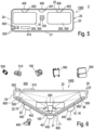
FIG.5 shows an embodiment of a straight-view multi-sensor housing 1300 with a single or multitude ofcamera sensors 100 for being assembled with a housing-integrated sensor- and cleaning-device 3 to a vehicle V like a PKW, this is a vehicle V ofFIG.1 or a commercial vehicle CV as described withFIG.2 orFIG.8 in particular. - In this further developed variant of a straight-
view sensor housing 1300, thesensor housing 1300 is in direct development of the aforementioned straight-view sensor housing 1201 with the addition that thesensor housing 1300 is adapted to house a multitude of sensors for monitoring environmental conditions of the vehicle V, CV. - In this case, three sensors of different kind are resided in the housing, which, however, are detachable and thus are able to be exchanged or replaced. In the instant case, the variant of
sensor housing 1300 again provides anadapter 10 resided in the housing to hold acamera sensor 100 and further adapters 10 (not shown in detail) are set aside therefrom to hold a LiDAR and/orRADAR sensor adapters 10 also of this multi-sensor housing for straight-view has a number of in this case three assembly fittings to hold thesensors - In this case, the variant of
sensor housing 1300 similar to the variant ofsensor housing 1201 holds thesensors wall 21 and casing back-wall 22 of thecasing 20. Thus, in this sense, themulti-sensor housing 1300 holds thesensors wall - Further, similar to the straight-view single-
sensor housing 1201, in this case a placeholder is integrated into the back-wall 22 of the housing to hold a multitude of washer-bodies sensors - In this case, the placeholder indicated by
reference sign 40 is adapted to hold all of the washer-bodies wall 22 of the casing. In the instant case, each of the washer-bodies sensors body body 400, which is in position as to effort cleaning of all the sensors in the sensor housing. - Also, similar to the embodiment of the
sensor housing 1201, in this case the multi-sensor straight-view sensor housing 1300 features a sensor and connector means 500 as described before with a sensor-connector 510 and a washer-connector 520 in the same manner as described before; this is, the sensor and connector means 500 is integrated into the housing at the inner side of the casing front-wall 21 and further adapted to connect all of thesensors sensor housing 1300. -
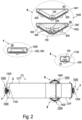
FIG.6 shows another qualitatively different kind ofmulti-sensor housing 1400 with a single or multitude ofcamera sensors 100 of a housing-integrated sensor- and cleaning-device 4 wherein for features of the same kind or same function, the same reference marks are used for simplicity; respectively, the above-mentioned description also applies to the further embodiment ofmulti-sensor housing 1400. -
FIG.6 shows variants of an angular-view multi-sensor housing view sensor housing multiple sensors camera sensors 100 to allow an increased coverage of a view angle angular field to the environment, preferably to allow an increased coverage of an angular field of near 120°or up to 180° or an even larger angular field for the view angle to the environment. - A sensor view angle in all cases is not perpendicular to a casing front-
wall 21 and a casing back-wall 22 but in an angle thereto in atrapezoidal casing 20; thus --as can be seen fromFIG.2 -- once the respective housing-integrated sensor- and cleaning-device - The
multi-sensor housing 1400, as mentioned before, can be adapted so as to provide an angular view of at least part of the sensors for monitoring environmental conditions of a vehicle, this is, the respective monitoring angle of the LiDAR and/orRADAR sensor - In the instant case, the
casing 20 of the angular viewmulti-sensor housing 1400 has two casing side-walls wall 22 with connector means 500 as described before, for instance withsensor housings - However, the casing front-
wall 21 in this case ofsensor housing 1400 is enlarged and provides a wide inner space of thetrapezoidal sensor housing 1400. This is afforded in that thefront side 21 provides asensor adapter 11 for thecamera sensor 100 and this, in combination with aLiDAR sensor 200 plus the outside casing front-wall 21 placeholder for the washer-body 401 of a cleaning-device in position as to afford cleaning of thecamera sensor 100 and theLiDAR sensor 200. The casing front-wall 21 functions as a carrier wall to hold thesensor adapter 11 and to integrate the placeholder and to integrate aheater element 600 as described before with, for instance, asensor housing - Further, the
trapezoidal casing 20 provides a left side angular casing front-wall 25 and a right side angular casing front-wall 26 in direct connection between casing front-wall 21 and casing side-walls walls - These are shown in more detail in view (A) of
FIG.7 for the left side part of the casing. This is the left side angular casing front-wall 25 again is used as a carrier wall for holding a sensor adapter 15 to hold aRADAR sensor 300, wherein here, this sensor adapter 15 has an assembly fitting to hold theRADAR sensor 300 in monitoring position. The monitoring position is plain with the angular casing front-wall 25 and thus allows an angular supervision of the environmental condition of the vehicle; the angle is set by the angle between angular casing front-wall 25 and back casingsidewall 22. - In a variant as shown in view (B) of
FIG.7 , again, the left side angular casing front-wall 25 is used as a carrier wall for holding a sensor adapter 13 integrating aheater element 600 and integrating aplaceholder 40 for the washer-body 402. - Further, the sensor adapter 13 --in variation to the sensor adapter 15 described before-- can be adapted in amending the acute angle α as described before; namely in diminishing the acute angle α to an even smaller acute angle β, which is smaller than the angle α. Thus, the originally fixed angular monitoring direction of an acute angle α can be flattened to an acute angle β, which is nearer to a straight-view monitoring direction for the
RADAR sensor 300. Acute angle in this case is to be understood not in a strict mathematical sense but more generally in that an acute angle α and acute angle β is to be understood generally as an angle different from 90°. - Thus, the angular casing front-
wall 25 of the angular viewmulti-sensor housing 1400 allows for theRADAR sensor 300 to be adapted in a monitoring angle between a large angle α to a lower monitoring angle β. It can be adapted even such that theRADAR sensor 300 could be used for straight view, when the adapting angle γ is set large enough to put theRADAR sensor 300 in parallel position to the casing back-wall 22 of thecasing 20. Corresponding measures are possible for aLiDAR sensor 200 instead of a RADAR sensor and also for any other kind of sensor like acamera sensor 100 instead. -
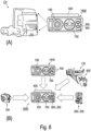
FIG.8 shows in view (A) a preferred fourth embodiment of asensor housing 1500 for a further kind of a housing-integrated sensor- and cleaning-device 5 for a commercial vehicle CV at exemplary positions indicated by arrows in view (A) ofFIG.8 . Exemplary positions indicate install positions at the vehicle, which favor integrated high-level ADAS solutions like smart corner monitors etc.. Thesensor housing 1500 is realized as a kind of head light sensor housing according to the concept of the invention. In particular thesensor housing 1500 can establish in addition to a standard headlamp function (not shown) an additional auxiliary head lamp function. - It should be noted that although the shape of housings indicated herewith has shown up to be of particular advantage; still nevertheless the
sensor housings 1500 can adopt another shape; e.g. as has been indicated before with regard to othermulti-sensor housings sensor housing 1500 can provide a position for a multitude ofcamera sensors 100 to allow an increased coverage of a view angle angular field to the environment, preferably to allow an increased coverage of an angular field of near 120°or up to 180° or an even larger angular field for the view angle to the environment. Thesensor housing 1500 also has been found to be of particular advantage to realize a smart corner application. - It should also be noted that although herein below the
sensor housing 1500 are shown and described to be assembled at a front and/or horizontal edge of a vehicle CV, still nevertheless saidsensor housing 1500 can also be assembled, respectively positioned, at any other position of any vehicle CV; this is in particular but not restricted saidsensor housing 1500 can also be assembled, respectively positioned, at a front and/or rear or at a corner or at a vertical or horizontal or other edge of a vehicle CV, even underneath or on top of a vehicle CV. - In particular the
sensor housing 1500 can establish in addition to a standard headlamp function (not shown) an additional auxiliary head lamp function at front and/or rear and/or side of the vehicle CV. Thesensor housing 1500 also has been found to be of particular advantage to realize a smart corner application. - In view (B) of
FIG.8 a way of implementation thereof with a washer-body 400 of a cleaning device CD of a cleaning system CDS, acamera sensor 100 or the like sensor means like in in this case also aLiDAR sensor 200 and/orRADAR sensor 300 and saidhead light 700. Thehead light 700 can be realized preferably as any kind of LED. Theheadlight 700 serves for any kind of visible and/or infrared illumination; this the available electro-magnetic spectrum of wavelength. This kind ofsensor housing 1500 shown inFIG.8 is in particular adapted for a commercial vehicle CV as shown in view (A). - This kind of
sensor housing 1500 thus further implements ahead light 700, wherein thehead light 700 is shown integrated in the middle next to thecamera 100 and next to theLiDAR sensor 200 and/orRADAR sensor 300; thus between them in thesensor housing 1500. - The head light in this case is integrated as a more or less intelligent main or auxiliary head lamp. The head
light sensor housing 1500 is of particular use for large scale commercial vehicles CV like the main truck machine shown in view (A) toFIG.8 but also in commercial vehicles CV of increased security standards like a school bus or a mining truck. It can thus be implemented for object and/or person detection but also in path finding, tracking and ADAS and the like smart applications during all day and night times. It can service a particular demand for a wide 3-D imaging in various ambient brightness and darkness conditions and in particular install positions at the vehicle, which favor integrated high-level ADAS solutions like smart corner monitors etc. - As can be seen form view (B) of
FIG.8 , this kind of embodiment ofsensor housing 1500 has been found to be of particular use as it has been found in shape analog or similar to the usual kind of headlight housing 1570. More particular the design reference is based on a headlight housing 1570 of a standard auxiliary headlamp and thus a housing's basis is readily available. This standard auxiliary headlamp of a headlight housing 1570 is used as housing's basis ofsensor housing 1500 further for integrating (indicated by arrows in view (B) ofFIG.8 ) the washer-body 400, thecamera sensor 100 or the like sensor means like in in this case a LiDAR and/orRADAR sensor FIG.8 . - Thus, the as such available standard auxiliary headlamp is adaptable as indicated in view (B) of
FIG.8 for the further embodiment of asensor housing 1500 to provide an intelligent housing-integrated sensor- and cleaning-device 5 according to the concept of the invention. -
- S
- sensoric system
- S100
- sensor
- S101
- sensor surface
- V
- vehicle
- V100
- vehicle pressurized air service arrangement
- V101
- compressor
- V102
- pressurized container
- MQA
- pressurized air reservoir
- MQL
- liquid reservoir
- V200
- vehicle pneumatic system
- V201
- springs
- V300
- vehicle cleaning system
- CDS
- cleaning-device system
- CD
- cleaning-device
- HFP
- hydraulic flow path to the liquid reservoir MQL
- AFP
- pressurized airflow path to the pressurized air reservoir MQA
- CV
- commercial vehicle
- CVT
- trailer of the commercial vehicle
- CVF
- traction vehicle
- 1A, 1B, 2A, 2C, 3, 4, 4A, 4B, 5
- housing-integrated sensor- and cleaning-device
- 10
- adapters
- 11, 12
- fixed sensor adapters
- 13, 14
- non-fixed first and second sensor adapter at angular casing front-wall
- 15, 16
- fixed first and second sensor adapter at angular casing front-wall
- 20
- casing
- 21
- casing front-wall
- 22
- casing back-wall
- 23, 24
- first and second casing sidewall
- 25, 26
- first and second angular casing front-wall
- 40
- placeholder
- 100, 200, 300
- sensor; camera, LiDAR, RADAR
- 400
- washer-body
- 401, 402, 403
- washer-bodies
- 500
- connector means
- 510
- sensor-connector
- 520
- washer-connector
- 600
- heater element
- 700
- head light
- 1000
- various sensor housings
- 1100, 1200
- single-sensor housings
- 1101, 1201
- variant of single-sensor housings
- 1300, 1400
- multi-sensor housings
- 1401, 1402
- variant of multi-sensor housings
- 1500
- head light sensor housing
- 1570
- head
light housing 1570
Claims (19)
- Housing-integrated sensor- and cleaning-device (1A, 1B, 2A, 2B, 3, 4, 4A, 4B) witha sensor housing (1000) for being assembled to a vehicle (V), in particular a commercial vehicle (CV), and a connector means (500) is integrated with the housing, wherein the sensor housing (1000) is further adapted to house at least one sensor (100, 200, 300, 400) to be connected to the connector means (500) and for monitoring environmental conditions of the vehicle (V), wherein a sensor adapter (10) is resided in the housing to hold the at least one sensor (100, 200, 300, 400),wherein the adapter (10) has a number of one or more assembly-fittings to hold the at least one sensor (100, 200, 300, 400) each in a monitoring position, and- a placeholder (40) is integrated with the housing to hold a washer-body of a cleaning-device in position as to afford cleaning of the at least one sensor,
anda cleaning-device (CD) connectable to a valve assembly (VA) by a pneumatic and hydraulic flow path (AFP, HFP) of a cleaning-device system (CDS) and a sensor (S) characterized in that- the cleaning-device (CD) is adapted for wash cleaning, in particular spray cleaning, of a sensor surface (S101) of the sensor (S), the cleaning-device (CD) comprising a washer-body (400) connectable by a washer supply-periphery with the valve assembly (VA), wherein- the valve assembly (VA) is adapted for control of selectively supplying liquid fluid from a liquid reservoir (MQL) to the liquid fluid inlet and/or pressurized air fluid from a pressurized air reservoir (MQA) to the pressurized air inlet. - Housing-integrated sensor- and cleaning-device (1A, 1B, 2A, 2B, 3, 4, 4A, 4B) of claim 1 characterized in that the number of one or more assembly-fittings are adapted to hold a multitude of sensors, namely a multitude of sensors of the same kind or a multitude of sensors of different kind.
- Housing-integrated sensor- and cleaning-device (1A, 1B, 2A, 2B, 3, 4, 4A, 4B) of claim 1 or 2 characterized in that the placeholder and/or connector means is part of the housing wall.
- Housing-integrated sensor- and cleaning-device (1A, 1B, 2A, 2B, 3, 4, 4A, 4B) of one of the claims 1 to 3 characterized in that the connector means (500) comprises- a sensor-connector (510) in form of an electronic interface to connect the sensor to a data- and/or energy-supply of the vehicle and- a washer-connector (520) in form of a connection fitting to connect the washer-body to the cleaning-device.
- Housing-integrated sensor- and cleaning-device (1A, 1B, 2A, 2B, 3, 4, 4A, 4B) of one of the claims 1 to 4 characterized in that the washer-body (400) is integrated with the sensor housing on the placeholder (40).
- Housing-integrated sensor- and cleaning-device (1A, 1B, 2A, 2B, 3, 4, 4A, 4B) of one of the claims 1 to 5 characterized in that an electronic interface plug and/or a supply-connection plug is integrated with the housing.
- Housing-integrated sensor- and cleaning-device (1A, 1B, 2A, 2B, 3, 4, 4A, 4B) of one of the claims 1 to 6 characterized in that the sensor adapter is resided at an inner side of the housing wall vis-à-vis the placeholder.
- Housing-integrated sensor- and cleaning-device (1A, 1B, 2A, 2B, 3, 4, 4A, 4B) of one of the claims 1 to 6 characterized in that the sensor housing (1000) has a carrier-wall, wherein the placeholder (40) is resided on an outer side of the carrier-wall and the sensor adapter is resided on an inner side of the carrier-wall.
- Housing-integrated sensor- and cleaning-device (1A, 1B, 2A, 2B, 3, 4, 4A, 4B) of one of the claims 1 to 8 characterized in that the placeholder and the sensor adapter are arranged vis-à-vis to each other, advantageously wherein the carrier wall is adapted to hold on the outer side the placeholder (40) and on an inner side the sensor adapter (10).
- Housing-integrated sensor- and cleaning-device (1A, 1B, 2A, 2B, 3, 4, 4A, 4B) of one of the claims 1 to 9 characterized in that the housing holds a heater element (600) and/or the heater element is integrated in a housing wall of the casing (20), in particular in the carrier-wall.
- Housing-integrated sensor- and cleaning-device (1A, 1B, 2A, 2B, 3, 4, 4A, 4B) of one of the claims 1 to 10 characterized in that the connector means (500) is placed in the housing away from the carrier-wall.
- Housing-integrated sensor- and cleaning-device (1A, 1B, 2A, 2B, 3, 4, 4A, 4B) of one of the claims 1 to 11 characterized in that the sensor adapter (10) and/or the carrier wall provides an adjustment means for tuning the monitoring position, in particular angular and/or placement position.
- Housing-integrated sensor- and cleaning-device (1A, 1B, 2A, 2B, 3, 4, 4A, 4B) of one of the claims 1 to 12 characterized in that the sensor adapter (10) and/or the placeholder (40) is detachable from the sensor housing, in particular from a housing wall of the casing (20).
- Housing-integrated sensor- and cleaning-device (1A, 1B, 2A, 2B, 3, 4, 4A, 4B) of one of the claims 1 to 13 characterized in that the sensor adapter (10) is adapted to receive a number of one or more sensors (100, 200, 300) and/or the placeholder (40) is adapted to receive a number of one or more washer-bodies (400, 401, 402, 403).
- Housing-integrated sensor- and cleaning-device (1A, 1B, 2A, 2B, 3, 4, 4A, 4B) of one of the claims 1 to 14 characterized in that the sensor (100, 200, 300) is one of the sensors selected from the group consisting of RADAR-, LiDAR-, optical sensor, in particular a camera and/or a lightening device, particularly a head light.
- Housing-integrated sensor- and cleaning-device (1A, 1B, 2A, 2B, 3, 4, 4A, 4B) of one of the claims 1 to 15 characterized in that the number of one or more assembly-fittings are adapted to hold a multitude of sensors, namely in combination a multitude of sensors of the kind: RADAR- and/or LiDAR and a camera and a lightening device, particularly a lightening device in form of a head light.
- Housing-integrated sensor- and cleaning-device (1A, 1B, 2A, 2B, 3, 4, 4A, 4B) of one of the claims 1 to 16 characterized in that the washer-body (400) is one of the washer-bodies selected from the group consisting of spray body, puls-jet body, liquid- and/or air flow body.
- Housing-integrated sensor- and cleaning-device of one of the claims 1 to 17, characterized in that the washer-body (400) has a washer-nozzle and a body housing, with a liquid fluid connection to a liquid inlet and a pressurized air fluid connection to a pressurized air inlet of the body housing, and a washer-path in the washer-nozzle for outputting a cleaning fluid to the sensor surface, in particular wherein the washer-body (400) is a spray body with a spray nozzle and a mixing chamber.
- Vehicle (V), in particular commercial vehicle (CV) with at least one housing-integrated sensor- and cleaning-device according to one of the claims 1-18, with at least one sensor,
wherein the at least one sensor (S100), is in particular of an ADAS-system.
Applications Claiming Priority (1)
| Application Number | Priority Date | Filing Date | Title |
|---|---|---|---|
| PCT/EP2020/072625 WO2022033673A1 (en) | 2020-08-12 | 2020-08-12 | Sensor housing, housing-integrated sensor- and cleaning-device and vehicle |
Publications (2)
| Publication Number | Publication Date |
|---|---|
| EP4196838A1 EP4196838A1 (en) | 2023-06-21 |
| EP4196838B1 true EP4196838B1 (en) | 2025-07-09 |
Family
ID=72148082
Family Applications (1)
| Application Number | Title | Priority Date | Filing Date |
|---|---|---|---|
| EP20758135.6A Active EP4196838B1 (en) | 2020-08-12 | 2020-08-12 | Sensor housing, housing-integrated sensor- and cleaning-device and vehicle |
Country Status (4)
| Country | Link |
|---|---|
| US (1) | US20230264660A1 (en) |
| EP (1) | EP4196838B1 (en) |
| CN (1) | CN116075765A (en) |
| WO (1) | WO2022033673A1 (en) |
Families Citing this family (5)
| Publication number | Priority date | Publication date | Assignee | Title |
|---|---|---|---|---|
| US12269436B2 (en) * | 2020-07-09 | 2025-04-08 | A. Raymond Et Cie | Bracket and modular assembly for fluid spray system |
| US20230322151A1 (en) * | 2020-09-15 | 2023-10-12 | Sandvik Mining And Construction Oy | Advanced light profile selection for a mining vehicle |
| KR20220126394A (en) * | 2021-03-09 | 2022-09-16 | (주)스마트레이더시스템 | fusion radar device |
| US20240393450A1 (en) * | 2023-05-24 | 2024-11-28 | Ford Global Technologies, Llc | Detection system for a vehicle |
| EP4660015A1 (en) * | 2024-06-05 | 2025-12-10 | Iveco S.P.A. | Improved support bracket for a vehicular sensor system |
Family Cites Families (17)
| Publication number | Priority date | Publication date | Assignee | Title |
|---|---|---|---|---|
| US5574426A (en) | 1995-06-30 | 1996-11-12 | Insys, Ltd. | Obstacle detection system for vehicles moving in reverse |
| US6834906B2 (en) * | 2002-12-30 | 2004-12-28 | Valeo Electrical Systems, Inc. | Vehicle liftgate with component module applique |
| CA2486287C (en) | 2003-10-30 | 2009-01-13 | Mark K. Swannie | Trailer hitch mounted reverse sensing system |
| DE202008003306U1 (en) | 2008-03-08 | 2008-09-18 | Wabco Gmbh | Device for arranging environmental sensors in a vehicle |
| US20120117745A1 (en) * | 2009-09-29 | 2012-05-17 | Denso Corporation | On-board optical sensor cover and on-board optical sensor apparatus |
| JP5803831B2 (en) * | 2012-07-23 | 2015-11-04 | 株式会社デンソー | In-vehicle optical sensor cleaning device |
| US9380190B2 (en) * | 2012-08-06 | 2016-06-28 | Gentex Corporation | Rotating lens apparatus |
| DE102014213283A1 (en) * | 2014-07-09 | 2016-01-14 | Application Solutions (Electronics and Vision) Ltd. | Camera system for a vehicle |
| DE102014010495B3 (en) * | 2014-07-16 | 2015-12-17 | Kautex Textron Gmbh & Co. Kg | Vehicle integrated vision and cleaning system |
| JP6768825B2 (en) * | 2016-03-16 | 2020-10-14 | ジェンテックス コーポレイション | Camera assembly with occluded image sensor circuit |
| NO343391B1 (en) * | 2017-06-15 | 2019-02-18 | Mostad Mekaniske As | Cleaning assembly for cleaning surface of vehicle-mounted camera or sensor |
| US10899275B2 (en) * | 2018-06-27 | 2021-01-26 | Magna Electronics Inc. | Vehicular camera with PCB focus tuning |
| DK180429B1 (en) * | 2018-11-20 | 2021-04-23 | Motional Ad Llc | Self-cleaning sensor housings |
| US11155243B2 (en) * | 2019-02-15 | 2021-10-26 | Global Ip Holdings, Llc | Optical system to facilitate vehicle operation, cleaning system to clean an optical element of the optical system and hollow protective plastic enclosure for use therein |
| EP3741632B1 (en) * | 2019-05-21 | 2023-09-06 | Fico Transpar, S.A. | Device and method for washing a surface of a motor vehicle part and fluid control valve for such device |
| DE102019214704A1 (en) * | 2019-09-25 | 2021-03-25 | Continental Automotive Gmbh | Cleaning device for cleaning a surface of a sensor device |
| US11478827B2 (en) * | 2019-10-01 | 2022-10-25 | Ford Global Technologies, Llc | Sensor assembly with cleaning |
-
2020
- 2020-08-12 EP EP20758135.6A patent/EP4196838B1/en active Active
- 2020-08-12 WO PCT/EP2020/072625 patent/WO2022033673A1/en not_active Ceased
- 2020-08-12 US US18/040,980 patent/US20230264660A1/en active Pending
- 2020-08-12 CN CN202080104198.1A patent/CN116075765A/en active Pending
Also Published As
| Publication number | Publication date |
|---|---|
| WO2022033673A1 (en) | 2022-02-17 |
| CN116075765A (en) | 2023-05-05 |
| EP4196838A1 (en) | 2023-06-21 |
| US20230264660A1 (en) | 2023-08-24 |
Similar Documents
| Publication | Publication Date | Title |
|---|---|---|
| EP4196838B1 (en) | Sensor housing, housing-integrated sensor- and cleaning-device and vehicle | |
| US11964617B2 (en) | Vehicular vision system with forward viewing camera module | |
| US11077801B2 (en) | Vehicular exterior rearview mirror assembly with blind spot indicator module | |
| US9487159B2 (en) | Vehicle vision system with camera module mounting bracket | |
| KR20210067087A (en) | Sensing apparatus | |
| CN109312765B (en) | Flow control system, jumper hose element, and fluid flow management method | |
| JP2019504801A (en) | Apparatus for cleaning automotive optical detection systems | |
| US11890991B2 (en) | Vehicular exterior rearview mirror assembly with blind spot indicator element |
Legal Events
| Date | Code | Title | Description |
|---|---|---|---|
| STAA | Information on the status of an ep patent application or granted ep patent |
Free format text: STATUS: UNKNOWN |
|
| STAA | Information on the status of an ep patent application or granted ep patent |
Free format text: STATUS: THE INTERNATIONAL PUBLICATION HAS BEEN MADE |
|
| PUAI | Public reference made under article 153(3) epc to a published international application that has entered the european phase |
Free format text: ORIGINAL CODE: 0009012 |
|
| STAA | Information on the status of an ep patent application or granted ep patent |
Free format text: STATUS: REQUEST FOR EXAMINATION WAS MADE |
|
| 17P | Request for examination filed |
Effective date: 20230313 |
|
| AK | Designated contracting states |
Kind code of ref document: A1 Designated state(s): AL AT BE BG CH CY CZ DE DK EE ES FI FR GB GR HR HU IE IS IT LI LT LU LV MC MK MT NL NO PL PT RO RS SE SI SK SM TR |
|
| DAV | Request for validation of the european patent (deleted) | ||
| DAX | Request for extension of the european patent (deleted) | ||
| GRAP | Despatch of communication of intention to grant a patent |
Free format text: ORIGINAL CODE: EPIDOSNIGR1 |
|
| STAA | Information on the status of an ep patent application or granted ep patent |
Free format text: STATUS: GRANT OF PATENT IS INTENDED |
|
| GRAS | Grant fee paid |
Free format text: ORIGINAL CODE: EPIDOSNIGR3 |
|
| GRAA | (expected) grant |
Free format text: ORIGINAL CODE: 0009210 |
|
| STAA | Information on the status of an ep patent application or granted ep patent |
Free format text: STATUS: THE PATENT HAS BEEN GRANTED |
|
| INTG | Intention to grant announced |
Effective date: 20250508 |
|
| AK | Designated contracting states |
Kind code of ref document: B1 Designated state(s): AL AT BE BG CH CY CZ DE DK EE ES FI FR GB GR HR HU IE IS IT LI LT LU LV MC MK MT NL NO PL PT RO RS SE SI SK SM TR |
|
| REG | Reference to a national code |
Ref country code: GB Ref legal event code: FG4D |
|
| REG | Reference to a national code |
Ref country code: CH Ref legal event code: EP |
|
| PGFP | Annual fee paid to national office [announced via postgrant information from national office to epo] |
Ref country code: FR Payment date: 20250623 Year of fee payment: 6 |
|
| REG | Reference to a national code |
Ref country code: IE Ref legal event code: FG4D |
|
| REG | Reference to a national code |
Ref country code: DE Ref legal event code: R096 Ref document number: 602020054214 Country of ref document: DE |
|
| PGFP | Annual fee paid to national office [announced via postgrant information from national office to epo] |
Ref country code: DE Payment date: 20250624 Year of fee payment: 6 |
|
| PGFP | Annual fee paid to national office [announced via postgrant information from national office to epo] |
Ref country code: GB Payment date: 20250723 Year of fee payment: 6 |
|
| REG | Reference to a national code |
Ref country code: NL Ref legal event code: MP Effective date: 20250709 |
|
| PG25 | Lapsed in a contracting state [announced via postgrant information from national office to epo] |
Ref country code: PT Free format text: LAPSE BECAUSE OF FAILURE TO SUBMIT A TRANSLATION OF THE DESCRIPTION OR TO PAY THE FEE WITHIN THE PRESCRIBED TIME-LIMIT Effective date: 20251110 |
|
| PG25 | Lapsed in a contracting state [announced via postgrant information from national office to epo] |
Ref country code: NL Free format text: LAPSE BECAUSE OF FAILURE TO SUBMIT A TRANSLATION OF THE DESCRIPTION OR TO PAY THE FEE WITHIN THE PRESCRIBED TIME-LIMIT Effective date: 20250709 |
|
| REG | Reference to a national code |
Ref country code: AT Ref legal event code: MK05 Ref document number: 1812350 Country of ref document: AT Kind code of ref document: T Effective date: 20250709 |
|
| PG25 | Lapsed in a contracting state [announced via postgrant information from national office to epo] |
Ref country code: IS Free format text: LAPSE BECAUSE OF FAILURE TO SUBMIT A TRANSLATION OF THE DESCRIPTION OR TO PAY THE FEE WITHIN THE PRESCRIBED TIME-LIMIT Effective date: 20251109 |
|
| PG25 | Lapsed in a contracting state [announced via postgrant information from national office to epo] |
Ref country code: NO Free format text: LAPSE BECAUSE OF FAILURE TO SUBMIT A TRANSLATION OF THE DESCRIPTION OR TO PAY THE FEE WITHIN THE PRESCRIBED TIME-LIMIT Effective date: 20251009 |
|
| REG | Reference to a national code |
Ref country code: LT Ref legal event code: MG9D |
|
| PG25 | Lapsed in a contracting state [announced via postgrant information from national office to epo] |
Ref country code: AT Free format text: LAPSE BECAUSE OF FAILURE TO SUBMIT A TRANSLATION OF THE DESCRIPTION OR TO PAY THE FEE WITHIN THE PRESCRIBED TIME-LIMIT Effective date: 20250709 |
|
| PG25 | Lapsed in a contracting state [announced via postgrant information from national office to epo] |
Ref country code: FI Free format text: LAPSE BECAUSE OF FAILURE TO SUBMIT A TRANSLATION OF THE DESCRIPTION OR TO PAY THE FEE WITHIN THE PRESCRIBED TIME-LIMIT Effective date: 20250709 |
|
| PG25 | Lapsed in a contracting state [announced via postgrant information from national office to epo] |
Ref country code: HR Free format text: LAPSE BECAUSE OF FAILURE TO SUBMIT A TRANSLATION OF THE DESCRIPTION OR TO PAY THE FEE WITHIN THE PRESCRIBED TIME-LIMIT Effective date: 20250709 |
|
| PG25 | Lapsed in a contracting state [announced via postgrant information from national office to epo] |
Ref country code: GR Free format text: LAPSE BECAUSE OF FAILURE TO SUBMIT A TRANSLATION OF THE DESCRIPTION OR TO PAY THE FEE WITHIN THE PRESCRIBED TIME-LIMIT Effective date: 20251010 |
|
| PG25 | Lapsed in a contracting state [announced via postgrant information from national office to epo] |
Ref country code: SE Free format text: LAPSE BECAUSE OF FAILURE TO SUBMIT A TRANSLATION OF THE DESCRIPTION OR TO PAY THE FEE WITHIN THE PRESCRIBED TIME-LIMIT Effective date: 20250709 |
|
| PG25 | Lapsed in a contracting state [announced via postgrant information from national office to epo] |
Ref country code: LV Free format text: LAPSE BECAUSE OF FAILURE TO SUBMIT A TRANSLATION OF THE DESCRIPTION OR TO PAY THE FEE WITHIN THE PRESCRIBED TIME-LIMIT Effective date: 20250709 |
|
| PG25 | Lapsed in a contracting state [announced via postgrant information from national office to epo] |
Ref country code: PL Free format text: LAPSE BECAUSE OF FAILURE TO SUBMIT A TRANSLATION OF THE DESCRIPTION OR TO PAY THE FEE WITHIN THE PRESCRIBED TIME-LIMIT Effective date: 20250709 Ref country code: BG Free format text: LAPSE BECAUSE OF FAILURE TO SUBMIT A TRANSLATION OF THE DESCRIPTION OR TO PAY THE FEE WITHIN THE PRESCRIBED TIME-LIMIT Effective date: 20250709 |
|
| PG25 | Lapsed in a contracting state [announced via postgrant information from national office to epo] |
Ref country code: RS Free format text: LAPSE BECAUSE OF FAILURE TO SUBMIT A TRANSLATION OF THE DESCRIPTION OR TO PAY THE FEE WITHIN THE PRESCRIBED TIME-LIMIT Effective date: 20251009 |
|
| PG25 | Lapsed in a contracting state [announced via postgrant information from national office to epo] |
Ref country code: ES Free format text: LAPSE BECAUSE OF FAILURE TO SUBMIT A TRANSLATION OF THE DESCRIPTION OR TO PAY THE FEE WITHIN THE PRESCRIBED TIME-LIMIT Effective date: 20250709 |
|
| PG25 | Lapsed in a contracting state [announced via postgrant information from national office to epo] |
Ref country code: RO Free format text: LAPSE BECAUSE OF FAILURE TO SUBMIT A TRANSLATION OF THE DESCRIPTION OR TO PAY THE FEE WITHIN THE PRESCRIBED TIME-LIMIT Effective date: 20250709 |
|
| REG | Reference to a national code |
Ref country code: CH Ref legal event code: H13 Free format text: ST27 STATUS EVENT CODE: U-0-0-H10-H13 (AS PROVIDED BY THE NATIONAL OFFICE) Effective date: 20260324 |
|
| PG25 | Lapsed in a contracting state [announced via postgrant information from national office to epo] |
Ref country code: SM Free format text: LAPSE BECAUSE OF FAILURE TO SUBMIT A TRANSLATION OF THE DESCRIPTION OR TO PAY THE FEE WITHIN THE PRESCRIBED TIME-LIMIT Effective date: 20250709 |
|
| PG25 | Lapsed in a contracting state [announced via postgrant information from national office to epo] |
Ref country code: DK Free format text: LAPSE BECAUSE OF FAILURE TO SUBMIT A TRANSLATION OF THE DESCRIPTION OR TO PAY THE FEE WITHIN THE PRESCRIBED TIME-LIMIT Effective date: 20250709 |
|
| PG25 | Lapsed in a contracting state [announced via postgrant information from national office to epo] |
Ref country code: LU Free format text: LAPSE BECAUSE OF NON-PAYMENT OF DUE FEES Effective date: 20250812 Ref country code: IT Free format text: LAPSE BECAUSE OF FAILURE TO SUBMIT A TRANSLATION OF THE DESCRIPTION OR TO PAY THE FEE WITHIN THE PRESCRIBED TIME-LIMIT Effective date: 20250709 |
|
| PG25 | Lapsed in a contracting state [announced via postgrant information from national office to epo] |
Ref country code: CH Free format text: LAPSE BECAUSE OF NON-PAYMENT OF DUE FEES Effective date: 20250831 Ref country code: CZ Free format text: LAPSE BECAUSE OF FAILURE TO SUBMIT A TRANSLATION OF THE DESCRIPTION OR TO PAY THE FEE WITHIN THE PRESCRIBED TIME-LIMIT Effective date: 20250709 |
|
| PG25 | Lapsed in a contracting state [announced via postgrant information from national office to epo] |
Ref country code: SK Free format text: LAPSE BECAUSE OF FAILURE TO SUBMIT A TRANSLATION OF THE DESCRIPTION OR TO PAY THE FEE WITHIN THE PRESCRIBED TIME-LIMIT Effective date: 20250709 Ref country code: EE Free format text: LAPSE BECAUSE OF FAILURE TO SUBMIT A TRANSLATION OF THE DESCRIPTION OR TO PAY THE FEE WITHIN THE PRESCRIBED TIME-LIMIT Effective date: 20250709 |