EP4196675B1 - Systems and methods for integrated fuel cell stack and battery management for transportation use - Google Patents
Systems and methods for integrated fuel cell stack and battery management for transportation use Download PDFInfo
- Publication number
- EP4196675B1 EP4196675B1 EP21791514.9A EP21791514A EP4196675B1 EP 4196675 B1 EP4196675 B1 EP 4196675B1 EP 21791514 A EP21791514 A EP 21791514A EP 4196675 B1 EP4196675 B1 EP 4196675B1
- Authority
- EP
- European Patent Office
- Prior art keywords
- power source
- fuel cell
- power
- integrated fuel
- signal
- Prior art date
- Legal status (The legal status is an assumption and is not a legal conclusion. Google has not performed a legal analysis and makes no representation as to the accuracy of the status listed.)
- Active
Links
Images

Classifications
-
- H—ELECTRICITY
- H02—GENERATION; CONVERSION OR DISTRIBUTION OF ELECTRIC POWER
- H02J—ELECTRIC POWER NETWORKS; CIRCUIT ARRANGEMENTS OR SYSTEMS FOR SUPPLYING OR DISTRIBUTING ELECTRIC POWER; SYSTEMS FOR STORING ELECTRIC ENERGY
- H02J1/00—Circuit arrangements for DC mains or DC distribution networks
- H02J1/10—Parallel operation of DC sources
- H02J1/108—Parallel operation of DC sources having arrangements for blocking reverse current flow, e.g. using diodes
-
- H—ELECTRICITY
- H02—GENERATION; CONVERSION OR DISTRIBUTION OF ELECTRIC POWER
- H02J—ELECTRIC POWER NETWORKS; CIRCUIT ARRANGEMENTS OR SYSTEMS FOR SUPPLYING OR DISTRIBUTING ELECTRIC POWER; SYSTEMS FOR STORING ELECTRIC ENERGY
- H02J1/00—Circuit arrangements for DC mains or DC distribution networks
- H02J1/10—Parallel operation of DC sources
- H02J1/102—Parallel operation of DC sources being switching converters
-
- F—MECHANICAL ENGINEERING; LIGHTING; HEATING; WEAPONS; BLASTING
- F02—COMBUSTION ENGINES; HOT-GAS OR COMBUSTION-PRODUCT ENGINE PLANTS
- F02K—JET-PROPULSION PLANTS
- F02K5/00—Plants including an engine, other than a gas turbine, driving a compressor or a ducted fan
-
- H—ELECTRICITY
- H02—GENERATION; CONVERSION OR DISTRIBUTION OF ELECTRIC POWER
- H02J—ELECTRIC POWER NETWORKS; CIRCUIT ARRANGEMENTS OR SYSTEMS FOR SUPPLYING OR DISTRIBUTING ELECTRIC POWER; SYSTEMS FOR STORING ELECTRIC ENERGY
- H02J2101/00—Supply or distribution of decentralised, dispersed or local electric power generation
- H02J2101/20—Dispersed power generation using renewable energy sources
- H02J2101/30—Fuel cells
-
- Y—GENERAL TAGGING OF NEW TECHNOLOGICAL DEVELOPMENTS; GENERAL TAGGING OF CROSS-SECTIONAL TECHNOLOGIES SPANNING OVER SEVERAL SECTIONS OF THE IPC; TECHNICAL SUBJECTS COVERED BY FORMER USPC CROSS-REFERENCE ART COLLECTIONS [XRACs] AND DIGESTS
- Y02—TECHNOLOGIES OR APPLICATIONS FOR MITIGATION OR ADAPTATION AGAINST CLIMATE CHANGE
- Y02E—REDUCTION OF GREENHOUSE GAS [GHG] EMISSIONS, RELATED TO ENERGY GENERATION, TRANSMISSION OR DISTRIBUTION
- Y02E60/00—Enabling technologies; Technologies with a potential or indirect contribution to GHG emissions mitigation
- Y02E60/30—Hydrogen technology
- Y02E60/50—Fuel cells
-
- Y—GENERAL TAGGING OF NEW TECHNOLOGICAL DEVELOPMENTS; GENERAL TAGGING OF CROSS-SECTIONAL TECHNOLOGIES SPANNING OVER SEVERAL SECTIONS OF THE IPC; TECHNICAL SUBJECTS COVERED BY FORMER USPC CROSS-REFERENCE ART COLLECTIONS [XRACs] AND DIGESTS
- Y02—TECHNOLOGIES OR APPLICATIONS FOR MITIGATION OR ADAPTATION AGAINST CLIMATE CHANGE
- Y02T—CLIMATE CHANGE MITIGATION TECHNOLOGIES RELATED TO TRANSPORTATION
- Y02T90/00—Enabling technologies or technologies with a potential or indirect contribution to GHG emissions mitigation
- Y02T90/40—Application of hydrogen technology to transportation, e.g. using fuel cells
Definitions
- This disclosure relates, in general, to clean energy-based air transportation systems technology and, more specifically, to systems and methods for integrated fuel cell stack and battery management for transportation use.
- a battery In a traditional fuel cell system used for transportation propulsion, a battery is used to provide power output bursts required by the application. For example, in a typical automotive application, a response time of 50ms is desired to human throttle inputs, which is an order of magnitude faster than the fastest fuel cell systems today.
- the gap is bridged by the battery system that is constantly connected to the fuel cell generator via a complex controllable DC to DC converter that manages power flow between the fuel cell and the battery, and then the battery is connected to the propulsive system via another complex power conversion system.
- the voltage levels of the fuel cell stack output can vary by more than 2x between the no-load and full rated load states. This creates additional complexity in power electronics design. The overall outcome is usually an expensive heavy system, wasting up to 10% of the energy in heat output from power conversion electronics at maximum rated power.
- US 2009/212634 A1 discloses a method of controlling dc/dc converter, method of controlling dc/dc converter apparatus, and method of controlling driving operation of electric vehicle.
- US 2004/228055 A1 discloses an ultracapacitor based power storage device suitable for use in hybrid fuel cell systems and other power systems that includes circuitry for simulating the response of a battery.
- This disclosure is directed to methods and systems that substantially obviate one or more of the above and other problems associated with conventional technology.
- this disclosure is directed to an integrated fuel cell power delivery system.
- the system includes a first power source configured to supply power to a propulsion inverter, a second power source configured to supply power to the propulsion inverter, a disconnect operably connected to the second power source, a bypass diode operably connected to the first power source and/or the second power source, a sensor that detects an output voltage of the integrated fuel cell power system, a processor, and a memory.
- the bypass diode and the disconnect selectively provide power to the propulsion inverter by the first power source and/or the second power source.
- the memory includes instructions stored thereon, which when executed by the processor, cause the integrated fuel cell power system to access a signal from the sensor, determine if the accessed first signal is greater than a first threshold voltage, and operably disconnect an output of at least one of the first power source or the second power source to the integrated fuel cell power system by the disconnect based on the determination; and an electronic voltage limiting device (102) configured to selectively provide a load on at least one of the first power source or second power source; wherein the instructions, when executed by the processor, further cause the integrated fuel cell power system to: access the first signal from the sensor; determine if the accessed first signal is greater than a third threshold voltage; and selectively provide a load, by the electronic voltage limiting device, to at least one of the first power source or second power source based on the determination, wherein the voltage limiting device includes a calibrated load configured to load the output of the integrated fuel cell power system in a case where the output voltage exceeds the predetermined third threshold voltage.
- the instructions when executed by the processor, may further cause the integrated fuel cell power system to access the first signal from the sensor, determine if the accessed first signal is less than a second threshold voltage, and operably connect the output of the second power source to the integrated fuel cell power system by the disconnect based on the determination.
- the first power source may include a fuel cell stack and/or a battery.
- the second power source may include a fuel cell stack and/or a battery.
- the electronic voltage limiting device may include a field-effect transistor (FET).
- FET field-effect transistor
- system may further include a cathode air compressor configured to be powered by the first power source and/or the second power source.
- the disclosure is directed to an integrated fuel cell power system including a first power source configured to supply power to a propulsion inverter, a second power source configured to supply power to the propulsion inverter, an electronic voltage limiting device configured to selectively provide a load on the first power source and/or second power source, a sensor that detects an output voltage of the integrated fuel cell power system, a processor, and a memory.
- the memory includes instructions stored thereon, which when executed by the processor, cause the integrated fuel cell power system to access a signal from the sensor, determine if the accessed first signal is greater than a threshold voltage, and selectively provide a load, by the electronic voltage limiting device, to the first power source and/or second power source based on the determination, wherein the voltage limiting device includes a calibrated load configured to load the output of the integrated fuel cell power system in a case where the output voltage exceeds the predetermined threshold.
- the voltage limiting device may include a field effect transistor (FET).
- FET field effect transistor
- system may further include a cathode air compressor configured to be powered by the first power source and/or the second power source.
- the first power source may include a fuel cell stack and/or a battery.
- the second power source may include a fuel cell stack and/or a battery.
- the disclosure is directed to a computer-implemented method for integrated fuel cell stack and battery management including accessing a signal from a sensor, the sensor configured to detect an output voltage of a first power source and/or a second power source, either individually or in series, determining if the accessed sensor signal is greater than a first threshold voltage, and operably disconnecting the output of the second power source by a power source disconnect based on the determination.
- the power source disconnect is operably connected to the first power source and the second power source.
- a plurality of bypass diodes and the power source disconnect are configured to selectively provide power to a propulsion inverter by the first power source and/or the second power source, either individually or simultaneously, the method further comprising: accessing the first signal from the sensor; determining if the accessed first signal is greater than a third threshold voltage; and selectively providing a load, by an electronic voltage limiting device, to at least one of the first power source or second power source based on the determination, wherein the electronic voltage limiting device is configured to selectively provide a load on at least one of the first power source or second power source, wherein the voltage limiting device includes a calibrated load configured to load the output of the integrated fuel cell power system in a case where the output voltage exceeds the predetermined second threshold voltage.
- the method may further include accessing the signal from the sensor, determining if the accessed first signal is less than a second threshold voltage, and operably connecting the output of the second power source to the integrated fuel cell power system by the disconnects based on the determination.
- the first power source may include a fuel cell stack and/or a battery.
- the second power source may include a fuel cell stack and/or a battery.
- the voltage limiting device may include a field-effect transistor (FET).
- FET field-effect transistor
- the integrated fuel cell power delivery system 100 generally includes a first power source 112 (e.g., the fuel cell system 200 and/or battery 111) connected substantially in series with a second power source 113, with individual disconnects 108a, 108b, and with bypass diodes 116b, 116c allowing the power flow even when the battery 111 or the fuel cell system 200 is selectively disconnected by the power source disconnect 108a, 108b.
- a first power source 112 e.g., the fuel cell system 200 and/or battery 111
- bypass diodes 116b, 116c bypass diodes
- High-quality bypass diodes 116b, 116c are inexpensive and light, and at typical 250V fuel cell stack (e.g., fuel cell system 200) / battery 111 voltage levels, the bypass diodes 116b, 116c may result in only about 0.3-0.5% losses in the system, compared to the state of the art system losses of up to about 10%, with the corresponding improvement in the complexity and weight of cooling systems for such a powertrain.
- the integrated fuel cell power delivery system 100 may include a controller 300 ( FIG. 3 ).
- the integrated fuel cell power delivery system 100 may further include an isolated DC to DC converter configured to charge the battery 111 with excess power from the fuel cell system 200.
- the integrated fuel cell power delivery system 100 also contains an output voltage sensor 106, an electronic voltage limiting device 102 (e.g., a field-effect transistor (FET)), that work together with the controller 300 to prevent overvoltage on the output of the integrated fuel cell power delivery system 100.
- the electronic voltage limiting device 102 may include, for example, a calibrated load/power resistor that is designed to load the output of the integrated fuel cell power delivery system 100 if the output voltage of the integrated fuel cell power delivery system 100 exceeds a predetermined value.
- the voltage sensor 106 may detect an output voltage of the integrated fuel cell power delivery system 100, and the electronic voltage limiting device 102 may open above a source-drain voltage of about 790V and switch in the electronic voltage limiting device 102 (e.g., the calibrated load) to provide sufficient load on the fuel cell system 200 to avoid overvoltage of the output voltage of the of the integrated fuel cell power delivery system 100, sufficient to manage most transient conditions (e.g., sudden load drop, before the controller 300 is able to reduce the fuel cell stack 200 and/or battery 111 output).
- the electronic voltage limiting device 102 e.g., the calibrated load
- a relatively small load e.g., 1% of the max power rating of the fuel cell
- a very significant voltage drop relative to the open-circuit voltage of the output of the integrated fuel cell power delivery system 100.
- the dissipated power across the load provided by the electronic voltage limiting device 102 can be redirected and used for useful purposes (e.g., heating of the passenger compartment, battery recharge, etc.).
- controller 300 reads the sensors, conducts necessary calculations, and produces commands delivered to the fuel cell system 200, power source disconnects 108a, 108b, and the electronic voltage limiting device 102.
- the proposed connection approach for the battery 111 and fuel cell system 200 results in the output voltage high enough to operate the propulsive system without an intermediate booster, yet without a possibility of overvoltage.
- the controller 300 connects the battery 111 to the output of the integrated fuel cell power delivery system 100 only when the peak / high output power of the integrated fuel cell power delivery system 100 is required.
- An example of a perfect application is an aircraft powertrain, where peak power is needed only on takeoff, while in cruise, only 50-70% of the peak power is required.
- the controller 300 connects the battery 111 into the circuit only for the takeoff and initial climb, producing full output voltage and power. Once the initial climb is complete, the power source disconnects the battery 111, and the powertrain operates on just a fuel cell system 200 at a steady output equivalent to 50-70% of the max system power rating.
- the battery 111 can be optionally recharged from the fuel cell 200 via an isolated DC to DC converter 110.
- DC to DC converter 110 would require a much lower power rating than the original booster converter and, therefore would be significantly cheaper and lighter.
- the overall system weight optimization can be achieved through balancing the battery 111 capacity (and therefore weight) and the converter power rating.
- a hydrogen fuel cell cathode air compressor 118 can be powered solely by battery power.
- the cathode air compressor 118 can be powered to bring up the hydrogen fuel cell voltage before closing the system power source disconnect 108b (see FIG. 1 ).
- the hydrogen fuel cell cathode air compressor 118 can be powered solely by the hydrogen fuel cell power while the system load is driven by the battery 111 and fuel cell system 200 in series.
- the battery 111 may be bypassed with a single-pole double-throw relay 122 (controlled by controller 300) on the positive end of the cathode air compressor 118 ( FIG. 2 ). Bypassing the battery 111 in this manner the power reserves of the system to be extended as much as possible (see FIG. 1 ).
- the hydrogen fuel cell cathode air compressor 118 can be powered off the fuel cell system 200 and/or the rechargeable battery 111 in series.
- the cathode air compressor 118 can be driven on the combined battery 111 and fuel cell voltage of fuel cell system 200 using the integrated fuel cell power delivery system 100 detailed in FIG. 1 .
- the combined voltage may be supplied to the cathode air compressor 118 (see FIG. 1 ).
- the hydrogen fuel cell cathode air compressor 118 can be started by the rechargeable battery 111 and transitioned to be run by the rechargeable battery 111 and fuel cell system 200 in series.
- the integrated fuel cell power delivery system 100 can start with the power source disconnect 108a open, effectively removing the fuel cell system 200 from the circuit, and allowing current to pass through the a bypass diode 116b, 116c. Power is applied to the cathode air compressor 118, voltage is then present across the fuel cell system 200, and then the power source disconnect 108a is closed to bring the integrated fuel cell power delivery system 100 to the full combined stack voltage (see FIG. 1 ).
- the fuel cell system 200 can charge the rechargeable battery 111 via an isolated DC to DC converter 110.
- the isolated DC to DC converter 110 can charge the battery 111 to extend the range of the integrated fuel cell power delivery system 100. This is desirable because hydrogen has a significant energy density advantage over the currently available battery technologies (see FIG. 1 ).
- the isolated DC to DC converter 110 may be configured to convert the approximately 300V fuel cell to an approximately 700V combined stack voltage if connected as an additive DC to DC converter.
- the electronic voltage limiting device 102 can be used such that the combined battery 111 and fuel cell system 200 output voltage cannot exceed a specified high voltage limit.
- a power resistor and a FET opening above 790V source-drain voltage can be utilized to provide sufficient load on the fuel cell to avoid overvoltage of the output supply - sufficient to manage most transient situations (e.g., sudden load drop, before the controller 300 is able to reduce the fuel cell output).
- this disclosure describes a method to remove the battery 111 if the battery is no longer desirable.
- the battery 111 can be taken out of the circuit by opening the power source disconnect 108a, 108b (see FIG. 1 ).
- the integrated fuel cell power delivery system power will then flow through the battery bypass diode keeping the integrated fuel cell power delivery system 100 powered.
- the fuel cell system 200 of integrated fuel cell power delivery system 100 which may be circular, can be coaxially supported on elongated shaft (e.g., concentric, not shown) of a powertrain of an integrated hydrogen-electric engine system of an aircraft (not shown), such that air channels 202 of fuel cell system 200 may be oriented in parallel relation with elongated shaft (e.g., horizontally, or left-to-right).
- Fuel cell system 200 may be in the form of a proton-exchange membrane fuel cell (PEMFC).
- PEMFC proton-exchange membrane fuel cell
- the fuel cells of the fuel cell system 200 are configured to convert chemical energy liberated during the electrochemical reaction of hydrogen and oxygen to electrical energy (e.g., direct current). Depleted air and water vapor are exhausted from fuel cell system 200.
- integrated fuel cell power delivery system 100 may include any number of external radiators (not shown) for facilitating airflow and adding, for instance, additional cooling.
- fuel cell system 200 can include liquid-cooled and/or air-cooled cell types so that cooling loads are integrated into heat exchangers (not shown) for reducing total amount of external radiators needed in the system.
- the fuel cell system 200 may include a fuel cell cathode air compressor 118 configured to supply air to the fuel cell system 200, a hydrogen fuel source 206 configured to supply hydrogen to the fuel cell system 200, and a hydrogen pressure regulating system 208 configured to regulate the hydrogen from the hydrogen fuel source 206 to the fuel cell system 200.
- FIG. 3 illustrates that controller 300 includes a processor 320 connected to a computer-readable storage medium or a memory 330.
- the computer-readable storage medium or memory 330 may be a volatile type of memory, e.g., RAM, or a non-volatile type of memory, e.g., flash media, disk media, etc.
- the processor 320 may be another type of processor such as, without limitation, a digital signal processor, a microprocessor, an ASIC, a graphics processing unit (GPU), a field-programmable gate array (FPGA), or a central processing unit (CPU).
- network inference may also be accomplished in systems that have weights implemented as memristors, chemically, or other inference calculations, as opposed to processors.
- the memory 330 can be random access memory, read-only memory, magnetic disk memory, solid-state memory, optical disc memory, and/or another type of memory. In some aspects of the disclosure, the memory 330 can be separate from the controller 300 and can communicate with the processor 320 through communication buses of a circuit board and/or through communication cables such as serial ATA cables or other types of cables.
- the memory 330 includes computer-readable instructions that are executable by the processor 320 to operate the controller 300.
- the controller 300 may include a network interface 340 to communicate with other computers or to a server.
- a storage device 310 may be used for storing data.
- the disclosed method may run on the controller 300 or on a user device, including, for example, on a mobile device, an IoT device, or a server system.
- the controller 300 is configured to receive among other data, the fuel supply status, aircraft location, and control, among other features, the pumps, motors, sensors, etc.
- the integrated hydrogen-electric engine system 100 can include any number and/or type of sensors, electrical components, and/or telemetry devices that are operatively coupled to controller 300 for facilitating the control, operation, and/or input/out of the various components of integrated hydrogen-electric engine system 100 for improving efficiencies and/or determining errors and/or failures of the various components.
- FIG. 4 there is shown a flow chart of an exemplary computer-implemented method 400 for integrated fuel cell stack and battery management in accordance with aspects of the present disclosure.
- the steps of FIG. 4 are shown in a particular order, the steps need not all be performed in the specified order, and certain steps can be performed in another order.
- FIG. 4 will be described below, with the controller 300 performing the operations.
- the operations of FIG. 4 may be performed in part by the controller 300 of FIG. 3 and in part by another device, such as a remote server. These variations are contemplated to be within the scope of the present disclosure.
- the controller 300 accesses a signal from a sensor configured to detect an output voltage of a first power source 112 or a second power source 113 (either individually or in series) of the integrated fuel cell power delivery system 100 of FIG. 1 .
- the first power source 112 and/or the second power source 113 may include any combination of fuel cell systems 200 and/or batteries 111.
- the first power source 112 may include a fuel cell system 200
- the second power source 113 may include the battery 111.
- the controller 300 determines if the accessed sensor signal is greater than a first threshold voltage (e.g., about 750Volts).
- a first threshold voltage e.g., about 750Volts
- the controller 300 operably disconnects an output of the second power source 113 by the power source disconnect(s) 108a, 108b, based on the determination that sensed voltage is greater than the first threshold voltage. For example, if the sensed voltage measures about 789 Volts, then the controller would determine that this is greater than the threshold of about 750 Volts and would disconnect the power source disconnect(s) 108a, 108b, to disconnect the output of the second power source 113 to reduce the system output voltage.
- the power source disconnect(s) 108a, 108b may be operably connected to the first power source and/or the second power source 113.
- the plurality of bypass diodes 116b and 116c and the power source disconnect(s) 108a, 108b are configured to selectively provide power to a propulsion inverter 29 by at least one of the first power source 112 or the second power source 113, either individually or simultaneously.
- the first power source 112 and/or the second power source 113 may power the cathode air compressor 118, which is operably connected to outputs of the integrated fuel cell power system 100.
- the controller 300 may determine if the accessed first signal is less than a second threshold voltage. In aspects, the controller 300 may operably connect the output of the second power source 113 to the integrated fuel cell power system 100 by the disconnects based on the determination. For example, if the sensed voltage is about 300 volts and the second threshold voltage is about 500 volts, then the controller 300 would operably connect the output of the second power source 113 to the integrated fuel cell power system 100.
- the controller 300 may determine if the accessed first signal is greater than a third threshold voltage (e.g., about 725Volts).
- a third threshold voltage e.g., about 725Volts.
- the controller 300 selectively provides a load, by an electronic voltage limiting device 102, to the first power source and/or second power source based on the determination the sensed voltage is greater than the third threshold voltage.
- the electronic voltage limiting device 102 is configured to selectively provide a load on at least one of the first power source 112 and/or second power source 113.
- the electronic voltage limiting device 102 may include a field-effect transistor (FET) and/or a precision resistor.
- FET field-effect transistor
- the electronic voltage limiting device 102 may open above about 725 volts to provide a sufficient load on the first power source 112 and/or second power source 113 to avoid overvoltage of the output of the integrated fuel cell power system 100.
- the electronic voltage limiting device 102 may include a calibrated load configured to load the output of the integrated fuel cell power system 100 in a case where the output voltage exceeds the predetermined third threshold voltage.
Landscapes
- Engineering & Computer Science (AREA)
- Power Engineering (AREA)
- Fuel Cell (AREA)
Description
- This disclosure relates, in general, to clean energy-based air transportation systems technology and, more specifically, to systems and methods for integrated fuel cell stack and battery management for transportation use.
- In a traditional fuel cell system used for transportation propulsion, a battery is used to provide power output bursts required by the application. For example, in a typical automotive application, a response time of 50ms is desired to human throttle inputs, which is an order of magnitude faster than the fastest fuel cell systems today. The gap is bridged by the battery system that is constantly connected to the fuel cell generator via a complex controllable DC to DC converter that manages power flow between the fuel cell and the battery, and then the battery is connected to the propulsive system via another complex power conversion system.
- In such a configuration, typical voltages of the fuel cell system and the buffer battery are limited to 200-250V due to the increasing cost and complexity of larger cell counts that would be required to support higher voltage. On the other hand, optimization of the propulsive part of the system (inverter + motor) demand higher voltages - typically 600-700V in today's high- performance propulsive systems. Therefore, a typical fuel cell architecture today deploys a boost converter to bring the voltage from 200-250V to 600-700V. Such a high boost ratio results in significant electrical stresses for all the power conversion components and relatively low efficiency of conversion.
- Additionally, the voltage levels of the fuel cell stack output can vary by more than 2x between the no-load and full rated load states. This creates additional complexity in power electronics design. The overall outcome is usually an expensive heavy system, wasting up to 10% of the energy in heat output from power conversion electronics at maximum rated power.
-
US 2009/212634 A1 discloses a method of controlling dc/dc converter, method of controlling dc/dc converter apparatus, and method of controlling driving operation of electric vehicle. -
US 2004/228055 A1 discloses an ultracapacitor based power storage device suitable for use in hybrid fuel cell systems and other power systems that includes circuitry for simulating the response of a battery. - This disclosure is directed to methods and systems that substantially obviate one or more of the above and other problems associated with conventional technology.
- In accordance with one aspect, this disclosure is directed to an integrated fuel cell power delivery system. The system includes a first power source configured to supply power to a propulsion inverter, a second power source configured to supply power to the propulsion inverter, a disconnect operably connected to the second power source, a bypass diode operably connected to the first power source and/or the second power source, a sensor that detects an output voltage of the integrated fuel cell power system, a processor, and a memory. The bypass diode and the disconnect selectively provide power to the propulsion inverter by the first power source and/or the second power source. The memory includes instructions stored thereon, which when executed by the processor, cause the integrated fuel cell power system to access a signal from the sensor, determine if the accessed first signal is greater than a first threshold voltage, and operably disconnect an output of at least one of the first power source or the second power source to the integrated fuel cell power system by the disconnect based on the determination; and an electronic voltage limiting device (102) configured to selectively provide a load on at least one of the first power source or second power source; wherein the instructions, when executed by the processor, further cause the integrated fuel cell power system to: access the first signal from the sensor; determine if the accessed first signal is greater than a third threshold voltage; and selectively provide a load, by the electronic voltage limiting device, to at least one of the first power source or second power source based on the determination, wherein the voltage limiting device includes a calibrated load configured to load the output of the integrated fuel cell power system in a case where the output voltage exceeds the predetermined third threshold voltage.
- In aspects, the instructions, when executed by the processor, may further cause the integrated fuel cell power system to access the first signal from the sensor, determine if the accessed first signal is less than a second threshold voltage, and operably connect the output of the second power source to the integrated fuel cell power system by the disconnect based on the determination.
- In aspects, the first power source may include a fuel cell stack and/or a battery.
- In aspects, the second power source may include a fuel cell stack and/or a battery.
- In aspects, the electronic voltage limiting device may include a field-effect transistor (FET).
- In aspects, the system may further include a cathode air compressor configured to be powered by the first power source and/or the second power source.
- According to yet another aspect, the disclosure is directed to an integrated fuel cell power system including a first power source configured to supply power to a propulsion inverter, a second power source configured to supply power to the propulsion inverter, an electronic voltage limiting device configured to selectively provide a load on the first power source and/or second power source, a sensor that detects an output voltage of the integrated fuel cell power system, a processor, and a memory. The memory includes instructions stored thereon, which when executed by the processor, cause the integrated fuel cell power system to access a signal from the sensor, determine if the accessed first signal is greater than a threshold voltage, and selectively provide a load, by the electronic voltage limiting device, to the first power source and/or second power source based on the determination, wherein the voltage limiting device includes a calibrated load configured to load the output of the integrated fuel cell power system in a case where the output voltage exceeds the predetermined threshold.
- In aspects, the voltage limiting device may include a field effect transistor (FET).
- In aspects, the system may further include a cathode air compressor configured to be powered by the first power source and/or the second power source.
- In aspects, the first power source may include a fuel cell stack and/or a battery.
- In aspects, the second power source may include a fuel cell stack and/or a battery.
- According to yet another aspect, the disclosure is directed to a computer-implemented method for integrated fuel cell stack and battery management including accessing a signal from a sensor, the sensor configured to detect an output voltage of a first power source and/or a second power source, either individually or in series, determining if the accessed sensor signal is greater than a first threshold voltage, and operably disconnecting the output of the second power source by a power source disconnect based on the determination. The power source disconnect is operably connected to the first power source and the second power source. A plurality of bypass diodes and the power source disconnect are configured to selectively provide power to a propulsion inverter by the first power source and/or the second power source, either individually or simultaneously, the method further comprising: accessing the first signal from the sensor; determining if the accessed first signal is greater than a third threshold voltage; and selectively providing a load, by an electronic voltage limiting device, to at least one of the first power source or second power source based on the determination, wherein the electronic voltage limiting device is configured to selectively provide a load on at least one of the first power source or second power source, wherein the voltage limiting device includes a calibrated load configured to load the output of the integrated fuel cell power system in a case where the output voltage exceeds the predetermined second threshold voltage.
- In aspects, the method may further include accessing the signal from the sensor, determining if the accessed first signal is less than a second threshold voltage, and operably connecting the output of the second power source to the integrated fuel cell power system by the disconnects based on the determination.
- In aspects, the first power source may include a fuel cell stack and/or a battery. The second power source may include a fuel cell stack and/or a battery.
- In aspects, the voltage limiting device may include a field-effect transistor (FET).
- Additional aspects related to this disclosure are set forth, in part, in the description which follows, and, in part, will be obvious from the description or may be learned by practice of this disclosure.
- It is to be understood that both the foregoing and the following descriptions are exemplary and explanatory only and are not intended to limit the claimed disclosure or application thereof in any manner whatsoever.
- The invention is defined by the features of the
independent claims 1, 7 and 12. Preferred embodiments are defined in the dependent claims. - The accompanying drawings, which are incorporated in and constitute a part of this specification, exemplify the aspects of the present disclosure and, together with the description, explain and illustrate the principles of this disclosure.
-
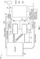
FIG. 1 is a schematic illustration of a hydrogen fuel cell-electric engine system; -
FIG. 2 is a schematic view of a fuel cell of the integrated hydrogen-electric engine system ofFIG. 1 ; -
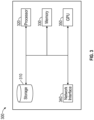
FIG. 3 is a block diagram of a controller configured for use with the integrated hydrogen-electric engine system ofFIG. 1 ; and -
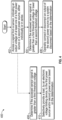
FIG. 4 is a block diagram of a computer-controlled method for integrated fuel cell stack and battery management for use with the integrated hydrogen-electric engine system ofFIG. 1 . - In the following detailed description, reference will be made to the accompanying drawing(s), in which identical functional elements are designated with like numerals. The accompanying drawings show by way of illustration, and not by way of limitation, specific aspects, and implementations consistent with principles of this disclosure.
- Referring to
FIG. 1 , the integrated fuel cellpower delivery system 100 generally includes a first power source 112 (e.g., thefuel cell system 200 and/or battery 111) connected substantially in series with asecond power source 113, withindividual disconnects bypass diodes 116b, 116c allowing the power flow even when thebattery 111 or thefuel cell system 200 is selectively disconnected by thepower source disconnect quality bypass diodes 116b, 116c are inexpensive and light, and at typical 250V fuel cell stack (e.g., fuel cell system 200) /battery 111 voltage levels, thebypass diodes 116b, 116c may result in only about 0.3-0.5% losses in the system, compared to the state of the art system losses of up to about 10%, with the corresponding improvement in the complexity and weight of cooling systems for such a powertrain. The integrated fuel cellpower delivery system 100 may include a controller 300 (FIG. 3 ). - The integrated fuel cell
power delivery system 100, may further include an isolated DC to DC converter configured to charge thebattery 111 with excess power from thefuel cell system 200. - Furthermore, the integrated fuel cell
power delivery system 100 also contains anoutput voltage sensor 106, an electronic voltage limiting device 102 (e.g., a field-effect transistor (FET)), that work together with thecontroller 300 to prevent overvoltage on the output of the integrated fuel cellpower delivery system 100. The electronicvoltage limiting device 102 may include, for example, a calibrated load/power resistor that is designed to load the output of the integrated fuel cellpower delivery system 100 if the output voltage of the integrated fuel cellpower delivery system 100 exceeds a predetermined value. For example, thevoltage sensor 106 may detect an output voltage of the integrated fuel cellpower delivery system 100, and the electronicvoltage limiting device 102 may open above a source-drain voltage of about 790V and switch in the electronic voltage limiting device 102 (e.g., the calibrated load) to provide sufficient load on thefuel cell system 200 to avoid overvoltage of the output voltage of the of the integrated fuel cellpower delivery system 100, sufficient to manage most transient conditions (e.g., sudden load drop, before thecontroller 300 is able to reduce thefuel cell stack 200 and/orbattery 111 output). Due to the typical characteristics of fuel cells, a relatively small load (e.g., 1% of the max power rating of the fuel cell) will result in a very significant voltage drop relative to the open-circuit voltage of the output of the integrated fuel cellpower delivery system 100. The dissipated power across the load provided by the electronicvoltage limiting device 102 can be redirected and used for useful purposes (e.g., heating of the passenger compartment, battery recharge, etc.). - Finally, the
controller 300 reads the sensors, conducts necessary calculations, and produces commands delivered to thefuel cell system 200,power source disconnects voltage limiting device 102. - In one or more aspects, the proposed connection approach for the
battery 111 andfuel cell system 200 results in the output voltage high enough to operate the propulsive system without an intermediate booster, yet without a possibility of overvoltage. - For example, the
controller 300 connects thebattery 111 to the output of the integrated fuel cellpower delivery system 100 only when the peak / high output power of the integrated fuel cellpower delivery system 100 is required. An example of a perfect application is an aircraft powertrain, where peak power is needed only on takeoff, while in cruise, only 50-70% of the peak power is required. In the case of such a power profile, thecontroller 300 connects thebattery 111 into the circuit only for the takeoff and initial climb, producing full output voltage and power. Once the initial climb is complete, the power source disconnects thebattery 111, and the powertrain operates on just afuel cell system 200 at a steady output equivalent to 50-70% of the max system power rating. - The
battery 111 can be optionally recharged from thefuel cell 200 via an isolated DC toDC converter 110. Such DC toDC converter 110 would require a much lower power rating than the original booster converter and, therefore would be significantly cheaper and lighter. The overall system weight optimization can be achieved through balancing thebattery 111 capacity (and therefore weight) and the converter power rating. - In aspects, a hydrogen fuel cell
cathode air compressor 118 can be powered solely by battery power. - For instance, before hydrogen and oxygen are supplied to the anode and cathode of the hydrogen
fuel cell system 200, thecathode air compressor 118 can be powered to bring up the hydrogen fuel cell voltage before closing the systempower source disconnect 108b (seeFIG. 1 ). - In aspects, the hydrogen fuel cell
cathode air compressor 118 can be powered solely by the hydrogen fuel cell power while the system load is driven by thebattery 111 andfuel cell system 200 in series. - For example, to reduce the energy required to recharge the
battery 111, thebattery 111 may be bypassed with a single-pole double-throw relay 122 (controlled by controller 300) on the positive end of the cathode air compressor 118 (FIG. 2 ). Bypassing thebattery 111 in this manner the power reserves of the system to be extended as much as possible (seeFIG. 1 ). - In aspects, the hydrogen fuel cell
cathode air compressor 118 can be powered off thefuel cell system 200 and/or therechargeable battery 111 in series. - For instance, to run the
cathode air compressor 118 efficiently and at full power thecathode air compressor 118 can be driven on the combinedbattery 111 and fuel cell voltage offuel cell system 200 using the integrated fuel cellpower delivery system 100 detailed inFIG. 1 . By closing both the battery and power source disconnects 108a, 108b, and not bypassing thebattery 111 with the double pole single throw relay 122, the combined voltage may be supplied to the cathode air compressor 118 (seeFIG. 1 ). - In aspects, the hydrogen fuel cell
cathode air compressor 118 can be started by therechargeable battery 111 and transitioned to be run by therechargeable battery 111 andfuel cell system 200 in series. - For example, the integrated fuel cell
power delivery system 100 can start with thepower source disconnect 108a open, effectively removing thefuel cell system 200 from the circuit, and allowing current to pass through the a bypass diode 116b, 116c. Power is applied to thecathode air compressor 118, voltage is then present across thefuel cell system 200, and then thepower source disconnect 108a is closed to bring the integrated fuel cellpower delivery system 100 to the full combined stack voltage (seeFIG. 1 ). - In aspects, the
fuel cell system 200 can charge therechargeable battery 111 via an isolated DC toDC converter 110. - For example, when excess power is available from the
fuel cell system 200, the isolated DC toDC converter 110 can charge thebattery 111 to extend the range of the integrated fuel cellpower delivery system 100. This is desirable because hydrogen has a significant energy density advantage over the currently available battery technologies (seeFIG. 1 ). - In aspects, the isolated DC to
DC converter 110 may be configured to convert the approximately 300V fuel cell to an approximately 700V combined stack voltage if connected as an additive DC to DC converter. - In aspects, the electronic
voltage limiting device 102 can be used such that the combinedbattery 111 andfuel cell system 200 output voltage cannot exceed a specified high voltage limit. - For instance, a power resistor and a FET opening above 790V source-drain voltage can be utilized to provide sufficient load on the fuel cell to avoid overvoltage of the output supply - sufficient to manage most transient situations (e.g., sudden load drop, before the
controller 300 is able to reduce the fuel cell output). - In aspects, this disclosure describes a method to remove the
battery 111 if the battery is no longer desirable. - For example, if the
battery 111 is depleted or no longer desired, it can be taken out of the circuit by opening thepower source disconnect FIG. 1 ). The integrated fuel cell power delivery system power will then flow through the battery bypass diode keeping the integrated fuel cellpower delivery system 100 powered. - With reference to
FIG. 2 , thefuel cell system 200 of integrated fuel cellpower delivery system 100, which may be circular, can be coaxially supported on elongated shaft (e.g., concentric, not shown) of a powertrain of an integrated hydrogen-electric engine system of an aircraft (not shown), such thatair channels 202 offuel cell system 200 may be oriented in parallel relation with elongated shaft (e.g., horizontally, or left-to-right).Fuel cell system 200 may be in the form of a proton-exchange membrane fuel cell (PEMFC). The fuel cells of thefuel cell system 200 are configured to convert chemical energy liberated during the electrochemical reaction of hydrogen and oxygen to electrical energy (e.g., direct current). Depleted air and water vapor are exhausted fromfuel cell system 200. The electrical energy generated fromfuel cell system 200 is then transmitted to a motor assembly (not shown), which is also coaxially/concentrically supported on elongated shaft (not shown). In aspects, integrated fuel cellpower delivery system 100 may include any number of external radiators (not shown) for facilitating airflow and adding, for instance, additional cooling. Notably,fuel cell system 200 can include liquid-cooled and/or air-cooled cell types so that cooling loads are integrated into heat exchangers (not shown) for reducing total amount of external radiators needed in the system. - In aspects, the
fuel cell system 200 may include a fuel cellcathode air compressor 118 configured to supply air to thefuel cell system 200, ahydrogen fuel source 206 configured to supply hydrogen to thefuel cell system 200, and a hydrogenpressure regulating system 208 configured to regulate the hydrogen from thehydrogen fuel source 206 to thefuel cell system 200. - Finally, the processes and techniques described herein are not inherently related to any particular apparatus and may be implemented by any suitable combination of components. Further, various types of general-purpose devices may be used in accordance with the teachings described herein. It may also prove advantageous to construct specialized apparatus to perform the method steps described herein. This disclosure has been described in relation to the examples, which are intended in all respects to be illustrative rather than restrictive.
-
FIG. 3 illustrates thatcontroller 300 includes aprocessor 320 connected to a computer-readable storage medium or amemory 330. The computer-readable storage medium ormemory 330 may be a volatile type of memory, e.g., RAM, or a non-volatile type of memory, e.g., flash media, disk media, etc. In various aspects of the disclosure, theprocessor 320 may be another type of processor such as, without limitation, a digital signal processor, a microprocessor, an ASIC, a graphics processing unit (GPU), a field-programmable gate array (FPGA), or a central processing unit (CPU). In certain aspects of the disclosure, network inference may also be accomplished in systems that have weights implemented as memristors, chemically, or other inference calculations, as opposed to processors. - In aspects of the disclosure, the
memory 330 can be random access memory, read-only memory, magnetic disk memory, solid-state memory, optical disc memory, and/or another type of memory. In some aspects of the disclosure, thememory 330 can be separate from thecontroller 300 and can communicate with theprocessor 320 through communication buses of a circuit board and/or through communication cables such as serial ATA cables or other types of cables. Thememory 330 includes computer-readable instructions that are executable by theprocessor 320 to operate thecontroller 300. In other aspects of the disclosure, thecontroller 300 may include anetwork interface 340 to communicate with other computers or to a server. Astorage device 310 may be used for storing data. - The disclosed method may run on the
controller 300 or on a user device, including, for example, on a mobile device, an IoT device, or a server system. Thecontroller 300 is configured to receive among other data, the fuel supply status, aircraft location, and control, among other features, the pumps, motors, sensors, etc. - Further, as can be appreciated, the integrated hydrogen-
electric engine system 100 can include any number and/or type of sensors, electrical components, and/or telemetry devices that are operatively coupled tocontroller 300 for facilitating the control, operation, and/or input/out of the various components of integrated hydrogen-electric engine system 100 for improving efficiencies and/or determining errors and/or failures of the various components. - Referring to
FIG. 4 , there is shown a flow chart of an exemplary computer-implementedmethod 400 for integrated fuel cell stack and battery management in accordance with aspects of the present disclosure. Although the steps ofFIG. 4 are shown in a particular order, the steps need not all be performed in the specified order, and certain steps can be performed in another order. For simplicity,FIG. 4 will be described below, with thecontroller 300 performing the operations. However, in various aspects, the operations ofFIG. 4 may be performed in part by thecontroller 300 ofFIG. 3 and in part by another device, such as a remote server. These variations are contemplated to be within the scope of the present disclosure. - Initially, at
step 402, thecontroller 300 accesses a signal from a sensor configured to detect an output voltage of afirst power source 112 or a second power source 113 (either individually or in series) of the integrated fuel cellpower delivery system 100 ofFIG. 1 . - The
first power source 112 and/or thesecond power source 113 may include any combination offuel cell systems 200 and/orbatteries 111. For example, thefirst power source 112 may include afuel cell system 200, and thesecond power source 113 may include thebattery 111. - Next, at
step 404, thecontroller 300 determines if the accessed sensor signal is greater than a first threshold voltage (e.g., about 750Volts). - Next, at
step 406, thecontroller 300 operably disconnects an output of thesecond power source 113 by the power source disconnect(s) 108a, 108b, based on the determination that sensed voltage is greater than the first threshold voltage. For example, if the sensed voltage measures about 789 Volts, then the controller would determine that this is greater than the threshold of about 750 Volts and would disconnect the power source disconnect(s) 108a, 108b, to disconnect the output of thesecond power source 113 to reduce the system output voltage. The power source disconnect(s) 108a, 108b, may be operably connected to the first power source and/or thesecond power source 113. The plurality ofbypass diodes 116b and 116c and the power source disconnect(s) 108a, 108b, are configured to selectively provide power to apropulsion inverter 29 by at least one of thefirst power source 112 or thesecond power source 113, either individually or simultaneously. - In aspects, the
first power source 112 and/or thesecond power source 113 may power thecathode air compressor 118, which is operably connected to outputs of the integrated fuelcell power system 100. - In aspects, the
controller 300 may determine if the accessed first signal is less than a second threshold voltage. In aspects, thecontroller 300 may operably connect the output of thesecond power source 113 to the integrated fuelcell power system 100 by the disconnects based on the determination. For example, if the sensed voltage is about 300 volts and the second threshold voltage is about 500 volts, then thecontroller 300 would operably connect the output of thesecond power source 113 to the integrated fuelcell power system 100. - In aspects, at
step 408, thecontroller 300 may determine if the accessed first signal is greater than a third threshold voltage (e.g., about 725Volts). Next, atstep 410, thecontroller 300 selectively provides a load, by an electronicvoltage limiting device 102, to the first power source and/or second power source based on the determination the sensed voltage is greater than the third threshold voltage. The electronicvoltage limiting device 102 is configured to selectively provide a load on at least one of thefirst power source 112 and/orsecond power source 113. - In aspects, the electronic
voltage limiting device 102, may include a field-effect transistor (FET) and/or a precision resistor. For example, to handle transient situations, the electronic voltage limiting device 102 (e.g., the FET) may open above about 725 volts to provide a sufficient load on thefirst power source 112 and/orsecond power source 113 to avoid overvoltage of the output of the integrated fuelcell power system 100. The electronicvoltage limiting device 102 may include a calibrated load configured to load the output of the integrated fuelcell power system 100 in a case where the output voltage exceeds the predetermined third threshold voltage.
Claims (15)
- An integrated fuel cell power delivery system (100), the system comprising:a first power source (112) configured to supply power to a propulsion inverter (29);a second power source (113) configured to supply power to the propulsion inverter;a disconnect (108b) operably connected to the second power source;a bypass diode (116b) operably connected to the first power source and the second power source, wherein the bypass diode and the disconnect selectively provides power to the propulsion inverter by at least one of the first power source or the second power source;a sensor (106) that detects an output voltage output by the integrated fuel cell power system;a processor;a memory, which includes instructions stored thereon, which when executed by the processor, cause the integrated fuel cell power system to:access a first signal from the sensor;determine if the accessed first signal is greater than a first threshold voltage; andoperably disconnect an output of at least one of the first power source or the second power source to the integrated fuel cell power system by the disconnect based on the determination; andan electronic voltage limiting device (102) configured to selectively provide a load on at least one of the first power source or second power source;wherein the instructions, when executed by the processor, further cause the integrated fuel cell power system to:access the first signal from the sensor;determine if the accessed first signal is greater than a third threshold voltage; andselectively provide a load, by the electronic voltage limiting device, to at least one of the first power source or second power source based on the determination,wherein the voltage limiting device includes a calibrated load configured to load the output of the integrated fuel cell power system in a case where the output voltage exceeds the predetermined third threshold voltage.
- The system according to claim 1, wherein the instructions, when executed by the processor, further cause the integrated fuel cell power system to:
access the first signal from the sensor;determine if the accessed first signal is less than a second threshold voltage; andoperably connect the output of the second power source to the integrated fuel cell power system by the disconnect based on the determination. - The system according to claim 1, wherein the first power source includes at least one of a fuel cell stack or a battery.
- The system according to claim 1, wherein the second power source includes at least one of a fuel cell stack or a battery.
- The system according to claim 1, wherein the electronic voltage limiting device includes a field effect transistor (FET).
- The system according to claim 1, further comprising a cathode air compressor configured to be powered by at least one of the first power source or the second power source.
- An integrated fuel cell power system (100), the system comprising:a first power source (112) configured to supply power to a propulsion inverter (29);a second power source (113) configured to supply power to the propulsion inverter;an electronic voltage limiting device (102) configured to selectively provide a load on at least one of the first power source or second power source;a sensor (106) that detects an output voltage of the integrated fuel cell power system;a processor; anda memory, which includes instructions stored thereon, which when executed by the processor, cause the integrated fuel cell power system to:wherein the voltage limiting device includes a calibrated load configured to load the output of the integrated fuel cell power system in a case where the output voltage exceeds the predetermined threshold.access a first signal from the sensor;determine if the accessed first signal is greater than a threshold voltage; andselectively provide a load, by the electronic voltage limiting device, to at least one of the first power source or second power source based on the determination,
- The system according to claim 7, wherein the voltage limiting device includes a field effect transistor (FET).
- The system according to claim 7, further comprising a cathode air compressor configured to be powered by at least one of the first power source or the second power source.
- The system according to claim 7, wherein the first power source includes at least one of a fuel cell stack or a battery.
- The system according to claim 7, wherein the second power source includes at least one of a fuel cell stack or a battery.
- A computer-implemented method for integrated fuel cell stack and battery management, the method comprising:accessing a signal from a sensor (106), the sensor configured to detect an output voltage of at least one of a first power source (112) or second power source (113), either individually or in series;determining if the accessed sensor signal is greater than a first threshold voltage; andoperably disconnecting an output of the second power source by a power source disconnect (108a, 108b) based on the determination,wherein the power source disconnect is operably connected to the second power source, andwherein a plurality of bypass diodes (116a, 116b) and the power source disconnect are configured to selectively provide power to a propulsion inverter by at least one of the first power source or the second power source, either individually or simultaneously, the method further comprising:wherein the voltage limiting device includes a calibrated load configured to load the output of the integrated fuel cell power system in a case where the output voltage exceeds the predetermined second threshold voltage.accessing the first signal from the sensor;determining if the accessed first signal is greater than a third threshold voltage; andselectively providing a load, by an electronic voltage limiting device, to at least one of the first power source or second power source based on the determination,wherein the electronic voltage limiting device is configured to selectively provide a load on at least one of the first power source or second power source,
- The computer-implemented method according to claim 12, further comprising:accessing the signal from the sensor;determining if the accessed first signal is less than a second threshold voltage; andoperably connecting the output of the second power source to the integrated fuel cell power system by the disconnects based on the determination.
- The computer-implemented method according to claim 12, wherein the first power source includes at least one of a fuel cell stack or a battery, and wherein the second power source includes at least one of a fuel cell stack or a battery.
- The system according to claim 1, wherein the voltage limiting device includes a field effect transistor (FET).
Applications Claiming Priority (2)
| Application Number | Priority Date | Filing Date | Title |
|---|---|---|---|
| US202063076382P | 2020-09-10 | 2020-09-10 | |
| PCT/US2021/049635 WO2022056107A1 (en) | 2020-09-10 | 2021-09-09 | Systems and methods for integrated fuel cell stack and battery management for transportation use |
Publications (2)
| Publication Number | Publication Date |
|---|---|
| EP4196675A1 EP4196675A1 (en) | 2023-06-21 |
| EP4196675B1 true EP4196675B1 (en) | 2024-11-20 |
Family
ID=78179503
Family Applications (1)
| Application Number | Title | Priority Date | Filing Date |
|---|---|---|---|
| EP21791514.9A Active EP4196675B1 (en) | 2020-09-10 | 2021-09-09 | Systems and methods for integrated fuel cell stack and battery management for transportation use |
Country Status (4)
| Country | Link |
|---|---|
| US (1) | US12444939B2 (en) |
| EP (1) | EP4196675B1 (en) |
| CA (1) | CA3192248A1 (en) |
| WO (1) | WO2022056107A1 (en) |
Families Citing this family (4)
| Publication number | Priority date | Publication date | Assignee | Title |
|---|---|---|---|---|
| US12341225B2 (en) | 2019-11-17 | 2025-06-24 | ZeroAvia, Inc. | Integrated hydrogen-electric engine |
| US12542287B2 (en) | 2019-11-17 | 2026-02-03 | ZeroAvia, Inc. | Fuel tank heat dissipation system for fuel cell cooling |
| US12444939B2 (en) | 2020-09-10 | 2025-10-14 | ZeroAvia, Inc. | Systems and methods for integrated fuel cell stack and battery management for transportation use |
| US12000404B1 (en) | 2023-08-30 | 2024-06-04 | ZeroAvia, Inc. | Inrunner axial compressor |
Family Cites Families (44)
| Publication number | Priority date | Publication date | Assignee | Title |
|---|---|---|---|---|
| US3801372A (en) | 1971-08-18 | 1974-04-02 | United Aircraft Corp | Fuel cell system comprising separate coolant loop and sensing means |
| US5106035A (en) | 1989-12-29 | 1992-04-21 | Aurora Flight Sciences Corporation | Aircraft propulsion system using air liquefaction and storage |
| US5810284A (en) | 1995-03-15 | 1998-09-22 | Hibbs; Bart D. | Aircraft |
| US6380637B1 (en) | 1996-09-19 | 2002-04-30 | Ztek Corporation | Off-board station and an electricity exchanging system suitable for use with a mobile vehicle power system |
| US6119979A (en) | 1997-09-15 | 2000-09-19 | Sky Station International, Inc. | Cyclical thermal management system |
| JPH11200888A (en) | 1998-01-19 | 1999-07-27 | Mitsubishi Heavy Ind Ltd | Fuel cell type turbine engine |
| DE19821952C2 (en) | 1998-05-15 | 2000-07-27 | Dbb Fuel Cell Engines Gmbh | Power supply unit on board an aircraft |
| JP4464474B2 (en) | 1998-06-25 | 2010-05-19 | トヨタ自動車株式会社 | FUEL CELL SYSTEM, FUEL CELL VEHICLE, AND FUEL CELL CONTROL METHOD |
| US6322915B1 (en) | 1999-07-20 | 2001-11-27 | International Fuel Cells Llc | Humidification system for a fuel cell power plant |
| CN1429165A (en) | 2000-04-03 | 2003-07-09 | 威罗门飞行公司 | Liquid hydrogen stratospheric aircraft |
| US6568633B2 (en) | 2000-08-24 | 2003-05-27 | James P. Dunn | Fuel cell powered electric aircraft |
| US6720102B2 (en) | 2001-11-21 | 2004-04-13 | Thomas C. Edwards | Rotating fuel cell |
| KR20030076259A (en) | 2002-03-19 | 2003-09-26 | 술저 헥시스 악티엔게젤샤프트 | A fuel cell battery with an integrated heat exchanger |
| JP2005526363A (en) * | 2002-05-16 | 2005-09-02 | バラード パワー システムズ インコーポレイティド | Power facility with an array of adjustable fuel cell systems |
| US6838923B2 (en) * | 2003-05-16 | 2005-01-04 | Ballard Power Systems Inc. | Power supply and ultracapacitor based battery simulator |
| WO2006039583A2 (en) | 2004-10-01 | 2006-04-13 | Pemery Corp. | Polymer electrolyte membrane fuel cell stack |
| US8043736B2 (en) | 2006-01-10 | 2011-10-25 | Honeywell International Inc. | Power generator having multiple layers of fuel cells |
| JP4935176B2 (en) | 2006-04-28 | 2012-05-23 | 株式会社エクォス・リサーチ | Separator unit and fuel cell stack |
| US8492046B2 (en) * | 2006-12-18 | 2013-07-23 | GM Global Technology Operations LLC | Method of mitigating fuel cell degradation due to startup and shutdown via hydrogen/nitrogen storage |
| CN201048143Y (en) | 2007-05-25 | 2008-04-16 | 上海神力科技有限公司 | Cooling fluid spraycup device |
| WO2009040112A2 (en) | 2007-09-25 | 2009-04-02 | Eads Deutschland Gmbh | Method for operating a gas turbine engine, power supplying device for conducting such method and aircraft using such method |
| GB2453127A (en) | 2007-09-26 | 2009-04-01 | Intelligent Energy Ltd | Fuel Cell System |
| JP4541425B2 (en) * | 2008-02-25 | 2010-09-08 | 本田技研工業株式会社 | DC / DC converter device |
| US9112197B1 (en) | 2009-06-17 | 2015-08-18 | Ravindra Kashyap | Fuel cell motor system |
| US8394518B2 (en) | 2009-06-26 | 2013-03-12 | Global Energy Science, LLC (California) | Galvanic electrochemical cells for generating alternating current electricity |
| EP2700120A1 (en) | 2011-04-21 | 2014-02-26 | Airbus Operations GmbH | Drive unit, method for providing power, and use of a drive unit |
| US9368965B2 (en) * | 2011-07-28 | 2016-06-14 | Tigo Energy, Inc. | Enhanced system and method for string-balancing |
| EP2878795B8 (en) | 2013-11-27 | 2016-10-12 | Airbus Operations GmbH | Engine for propelling an aircraft and aircraft having at least one engine and at least one hydrogen tank |
| DE102014119279A1 (en) | 2014-12-19 | 2016-06-23 | Airbus Operations Gmbh | Auxiliary power system for an aircraft and an aircraft with such an auxiliary power system |
| DE102015003028A1 (en) | 2015-03-10 | 2016-09-15 | Daimler Ag | Cooling arrangement for cooling a fuel cell |
| US10450886B2 (en) | 2015-12-22 | 2019-10-22 | General Electric Company | Hybrid propulsion system including a chemically rechargeable ultra-capacitor |
| US10774741B2 (en) | 2016-01-26 | 2020-09-15 | General Electric Company | Hybrid propulsion system for a gas turbine engine including a fuel cell |
| US10875406B2 (en) * | 2017-01-19 | 2020-12-29 | Solaredge Technologies Ltd. | Electric-vehicle charging apparatus |
| US10703496B2 (en) | 2017-04-21 | 2020-07-07 | General Electric Company | Propulsion system for an aircraft |
| EP3781299B1 (en) | 2018-04-17 | 2025-09-03 | Electriq-Global Energy Solutions Ltd. | A hydrogen reactor with catalyst in flow conduit |
| KR102169149B1 (en) | 2018-11-29 | 2020-10-23 | 건설기계부품연구원 | Low pressure metal hybrid type hydrogen storage and emitting system for fuel cell |
| JP6827254B2 (en) | 2019-01-04 | 2021-02-10 | ブリリアント ライト パワー インコーポレーティド | Power generation system and methods related to the system |
| JP7136040B2 (en) | 2019-08-06 | 2022-09-13 | トヨタ自動車株式会社 | fuel cell unit |
| US12542287B2 (en) | 2019-11-17 | 2026-02-03 | ZeroAvia, Inc. | Fuel tank heat dissipation system for fuel cell cooling |
| US20220325666A1 (en) | 2019-11-17 | 2022-10-13 | ZeroAvia, Inc. | Use cowling and other surfaces with large airflows as heat dissipation devices for fc cooling |
| US12341225B2 (en) | 2019-11-17 | 2025-06-24 | ZeroAvia, Inc. | Integrated hydrogen-electric engine |
| US11764679B2 (en) * | 2020-01-15 | 2023-09-19 | Solaredge Technologies Ltd. | Power device |
| US11862780B2 (en) * | 2020-02-21 | 2024-01-02 | ZeroAvia, Inc. | Fuel cell—battery hybrid system for transportation use |
| US12444939B2 (en) | 2020-09-10 | 2025-10-14 | ZeroAvia, Inc. | Systems and methods for integrated fuel cell stack and battery management for transportation use |
-
2021
- 2021-09-09 US US18/044,064 patent/US12444939B2/en active Active
- 2021-09-09 CA CA3192248A patent/CA3192248A1/en active Pending
- 2021-09-09 EP EP21791514.9A patent/EP4196675B1/en active Active
- 2021-09-09 WO PCT/US2021/049635 patent/WO2022056107A1/en not_active Ceased
Also Published As
| Publication number | Publication date |
|---|---|
| CA3192248A1 (en) | 2022-03-17 |
| US12444939B2 (en) | 2025-10-14 |
| WO2022056107A1 (en) | 2022-03-17 |
| US20230352936A1 (en) | 2023-11-02 |
| EP4196675A1 (en) | 2023-06-21 |
Similar Documents
| Publication | Publication Date | Title |
|---|---|---|
| EP4196675B1 (en) | Systems and methods for integrated fuel cell stack and battery management for transportation use | |
| US7438984B2 (en) | Electric system for fuel cell, fuel cell vehicle, and method of supplying electric power | |
| JP5434195B2 (en) | Fuel cell system and vehicle equipped with the same | |
| US8084988B2 (en) | Power supply system | |
| US11862780B2 (en) | Fuel cell—battery hybrid system for transportation use | |
| US10279699B2 (en) | On-board electrical system, and method for operating an on-board electrical system | |
| US7049788B2 (en) | Power source device for electric motor | |
| CN110834553A (en) | External power supply system and power supply method for fuel cell vehicle | |
| CN104340082A (en) | Fuel cell vehicle | |
| JPWO2019035172A1 (en) | Vehicle power supply system | |
| US7527112B2 (en) | Electric system for fuel cell, fuel cell vehicle, and method of supplying electric power | |
| US11962147B2 (en) | Circuit and system for coupling battery packs to motor controller in electric or hybrid aircraft | |
| US7911183B2 (en) | Voltage control system and vehicle comprising voltage control system | |
| US9889766B2 (en) | Electric power system | |
| JP5509655B2 (en) | Fuel cell system and vehicle equipped with the same | |
| US11318855B2 (en) | Motor vehicle having an electric machine as a drive machine and method for operating a DC-DC converter in a motor vehicle | |
| US12580213B2 (en) | Fuel cell system | |
| JP7384192B2 (en) | fuel cell car | |
| CN113013971B (en) | Voltage stabilization control method, device, hybrid power system and storage medium | |
| EP4298703A1 (en) | Fuel cell - battery hybrid system for transportation use | |
| CN112740499B (en) | Electric vehicle control method and electric vehicle system | |
| US20220305957A1 (en) | Vehicle |
Legal Events
| Date | Code | Title | Description |
|---|---|---|---|
| STAA | Information on the status of an ep patent application or granted ep patent |
Free format text: STATUS: UNKNOWN |
|
| STAA | Information on the status of an ep patent application or granted ep patent |
Free format text: STATUS: THE INTERNATIONAL PUBLICATION HAS BEEN MADE |
|
| PUAI | Public reference made under article 153(3) epc to a published international application that has entered the european phase |
Free format text: ORIGINAL CODE: 0009012 |
|
| STAA | Information on the status of an ep patent application or granted ep patent |
Free format text: STATUS: REQUEST FOR EXAMINATION WAS MADE |
|
| 17P | Request for examination filed |
Effective date: 20230317 |
|
| AK | Designated contracting states |
Kind code of ref document: A1 Designated state(s): AL AT BE BG CH CY CZ DE DK EE ES FI FR GB GR HR HU IE IS IT LI LT LU LV MC MK MT NL NO PL PT RO RS SE SI SK SM TR |
|
| DAV | Request for validation of the european patent (deleted) | ||
| DAX | Request for extension of the european patent (deleted) | ||
| GRAP | Despatch of communication of intention to grant a patent |
Free format text: ORIGINAL CODE: EPIDOSNIGR1 |
|
| STAA | Information on the status of an ep patent application or granted ep patent |
Free format text: STATUS: GRANT OF PATENT IS INTENDED |
|
| INTG | Intention to grant announced |
Effective date: 20240517 |
|
| GRAS | Grant fee paid |
Free format text: ORIGINAL CODE: EPIDOSNIGR3 |
|
| GRAA | (expected) grant |
Free format text: ORIGINAL CODE: 0009210 |
|
| STAA | Information on the status of an ep patent application or granted ep patent |
Free format text: STATUS: THE PATENT HAS BEEN GRANTED |
|
| AK | Designated contracting states |
Kind code of ref document: B1 Designated state(s): AL AT BE BG CH CY CZ DE DK EE ES FI FR GB GR HR HU IE IS IT LI LT LU LV MC MK MT NL NO PL PT RO RS SE SI SK SM TR |
|
| REG | Reference to a national code |
Ref country code: GB Ref legal event code: FG4D |
|
| REG | Reference to a national code |
Ref country code: CH Ref legal event code: EP |
|
| REG | Reference to a national code |
Ref country code: DE Ref legal event code: R096 Ref document number: 602021022156 Country of ref document: DE |
|
| REG | Reference to a national code |
Ref country code: IE Ref legal event code: FG4D |
|
| REG | Reference to a national code |
Ref country code: LT Ref legal event code: MG9D |
|
| REG | Reference to a national code |
Ref country code: NL Ref legal event code: MP Effective date: 20241120 |
|
| PG25 | Lapsed in a contracting state [announced via postgrant information from national office to epo] |
Ref country code: IS Free format text: LAPSE BECAUSE OF FAILURE TO SUBMIT A TRANSLATION OF THE DESCRIPTION OR TO PAY THE FEE WITHIN THE PRESCRIBED TIME-LIMIT Effective date: 20250320 Ref country code: HR Free format text: LAPSE BECAUSE OF FAILURE TO SUBMIT A TRANSLATION OF THE DESCRIPTION OR TO PAY THE FEE WITHIN THE PRESCRIBED TIME-LIMIT Effective date: 20241120 Ref country code: PT Free format text: LAPSE BECAUSE OF FAILURE TO SUBMIT A TRANSLATION OF THE DESCRIPTION OR TO PAY THE FEE WITHIN THE PRESCRIBED TIME-LIMIT Effective date: 20250320 |
|
| PG25 | Lapsed in a contracting state [announced via postgrant information from national office to epo] |
Ref country code: FI Free format text: LAPSE BECAUSE OF FAILURE TO SUBMIT A TRANSLATION OF THE DESCRIPTION OR TO PAY THE FEE WITHIN THE PRESCRIBED TIME-LIMIT Effective date: 20241120 Ref country code: NL Free format text: LAPSE BECAUSE OF FAILURE TO SUBMIT A TRANSLATION OF THE DESCRIPTION OR TO PAY THE FEE WITHIN THE PRESCRIBED TIME-LIMIT Effective date: 20241120 |
|
| REG | Reference to a national code |
Ref country code: AT Ref legal event code: MK05 Ref document number: 1743785 Country of ref document: AT Kind code of ref document: T Effective date: 20241120 |
|
| PG25 | Lapsed in a contracting state [announced via postgrant information from national office to epo] |
Ref country code: BG Free format text: LAPSE BECAUSE OF FAILURE TO SUBMIT A TRANSLATION OF THE DESCRIPTION OR TO PAY THE FEE WITHIN THE PRESCRIBED TIME-LIMIT Effective date: 20241120 |
|
| PG25 | Lapsed in a contracting state [announced via postgrant information from national office to epo] |
Ref country code: ES Free format text: LAPSE BECAUSE OF FAILURE TO SUBMIT A TRANSLATION OF THE DESCRIPTION OR TO PAY THE FEE WITHIN THE PRESCRIBED TIME-LIMIT Effective date: 20241120 |
|
| PG25 | Lapsed in a contracting state [announced via postgrant information from national office to epo] |
Ref country code: NO Free format text: LAPSE BECAUSE OF FAILURE TO SUBMIT A TRANSLATION OF THE DESCRIPTION OR TO PAY THE FEE WITHIN THE PRESCRIBED TIME-LIMIT Effective date: 20250220 |
|
| PG25 | Lapsed in a contracting state [announced via postgrant information from national office to epo] |
Ref country code: AT Free format text: LAPSE BECAUSE OF FAILURE TO SUBMIT A TRANSLATION OF THE DESCRIPTION OR TO PAY THE FEE WITHIN THE PRESCRIBED TIME-LIMIT Effective date: 20241120 Ref country code: LV Free format text: LAPSE BECAUSE OF FAILURE TO SUBMIT A TRANSLATION OF THE DESCRIPTION OR TO PAY THE FEE WITHIN THE PRESCRIBED TIME-LIMIT Effective date: 20241120 Ref country code: GR Free format text: LAPSE BECAUSE OF FAILURE TO SUBMIT A TRANSLATION OF THE DESCRIPTION OR TO PAY THE FEE WITHIN THE PRESCRIBED TIME-LIMIT Effective date: 20250221 |
|
| PG25 | Lapsed in a contracting state [announced via postgrant information from national office to epo] |
Ref country code: PL Free format text: LAPSE BECAUSE OF FAILURE TO SUBMIT A TRANSLATION OF THE DESCRIPTION OR TO PAY THE FEE WITHIN THE PRESCRIBED TIME-LIMIT Effective date: 20241120 |
|
| PG25 | Lapsed in a contracting state [announced via postgrant information from national office to epo] |
Ref country code: RS Free format text: LAPSE BECAUSE OF FAILURE TO SUBMIT A TRANSLATION OF THE DESCRIPTION OR TO PAY THE FEE WITHIN THE PRESCRIBED TIME-LIMIT Effective date: 20250220 |
|
| PG25 | Lapsed in a contracting state [announced via postgrant information from national office to epo] |
Ref country code: SM Free format text: LAPSE BECAUSE OF FAILURE TO SUBMIT A TRANSLATION OF THE DESCRIPTION OR TO PAY THE FEE WITHIN THE PRESCRIBED TIME-LIMIT Effective date: 20241120 |
|
| PG25 | Lapsed in a contracting state [announced via postgrant information from national office to epo] |
Ref country code: DK Free format text: LAPSE BECAUSE OF FAILURE TO SUBMIT A TRANSLATION OF THE DESCRIPTION OR TO PAY THE FEE WITHIN THE PRESCRIBED TIME-LIMIT Effective date: 20241120 |
|
| PG25 | Lapsed in a contracting state [announced via postgrant information from national office to epo] |
Ref country code: EE Free format text: LAPSE BECAUSE OF FAILURE TO SUBMIT A TRANSLATION OF THE DESCRIPTION OR TO PAY THE FEE WITHIN THE PRESCRIBED TIME-LIMIT Effective date: 20241120 |
|
| PG25 | Lapsed in a contracting state [announced via postgrant information from national office to epo] |
Ref country code: RO Free format text: LAPSE BECAUSE OF FAILURE TO SUBMIT A TRANSLATION OF THE DESCRIPTION OR TO PAY THE FEE WITHIN THE PRESCRIBED TIME-LIMIT Effective date: 20241120 |
|
| PG25 | Lapsed in a contracting state [announced via postgrant information from national office to epo] |
Ref country code: SK Free format text: LAPSE BECAUSE OF FAILURE TO SUBMIT A TRANSLATION OF THE DESCRIPTION OR TO PAY THE FEE WITHIN THE PRESCRIBED TIME-LIMIT Effective date: 20241120 |
|
| PG25 | Lapsed in a contracting state [announced via postgrant information from national office to epo] |
Ref country code: CZ Free format text: LAPSE BECAUSE OF FAILURE TO SUBMIT A TRANSLATION OF THE DESCRIPTION OR TO PAY THE FEE WITHIN THE PRESCRIBED TIME-LIMIT Effective date: 20241120 |
|
| PG25 | Lapsed in a contracting state [announced via postgrant information from national office to epo] |
Ref country code: IT Free format text: LAPSE BECAUSE OF FAILURE TO SUBMIT A TRANSLATION OF THE DESCRIPTION OR TO PAY THE FEE WITHIN THE PRESCRIBED TIME-LIMIT Effective date: 20241120 |
|
| REG | Reference to a national code |
Ref country code: DE Ref legal event code: R097 Ref document number: 602021022156 Country of ref document: DE |
|
| PG25 | Lapsed in a contracting state [announced via postgrant information from national office to epo] |
Ref country code: SE Free format text: LAPSE BECAUSE OF FAILURE TO SUBMIT A TRANSLATION OF THE DESCRIPTION OR TO PAY THE FEE WITHIN THE PRESCRIBED TIME-LIMIT Effective date: 20241120 |
|
| PLBE | No opposition filed within time limit |
Free format text: ORIGINAL CODE: 0009261 |
|
| STAA | Information on the status of an ep patent application or granted ep patent |
Free format text: STATUS: NO OPPOSITION FILED WITHIN TIME LIMIT |
|
| PGFP | Annual fee paid to national office [announced via postgrant information from national office to epo] |
Ref country code: DE Payment date: 20250929 Year of fee payment: 5 |
|
| 26N | No opposition filed |
Effective date: 20250821 |