EP4195891A1 - An inverter board casing - Google Patents
An inverter board casing Download PDFInfo
- Publication number
- EP4195891A1 EP4195891A1 EP22199107.8A EP22199107A EP4195891A1 EP 4195891 A1 EP4195891 A1 EP 4195891A1 EP 22199107 A EP22199107 A EP 22199107A EP 4195891 A1 EP4195891 A1 EP 4195891A1
- Authority
- EP
- European Patent Office
- Prior art keywords
- receptacle
- wall
- inverter board
- casing
- cover
- Prior art date
- Legal status (The legal status is an assumption and is not a legal conclusion. Google has not performed a legal analysis and makes no representation as to the accuracy of the status listed.)
- Granted
Links
Images
Classifications
-
- H—ELECTRICITY
- H05—ELECTRIC TECHNIQUES NOT OTHERWISE PROVIDED FOR
- H05K—PRINTED CIRCUITS; CASINGS OR CONSTRUCTIONAL DETAILS OF ELECTRIC APPARATUS; MANUFACTURE OF ASSEMBLAGES OF ELECTRICAL COMPONENTS
- H05K7/00—Constructional details common to different types of electric apparatus
- H05K7/14—Mounting supporting structure in casing or on frame or rack
- H05K7/1422—Printed circuit boards receptacles, e.g. stacked structures, electronic circuit modules or box like frames
- H05K7/1427—Housings
- H05K7/1432—Housings specially adapted for power drive units or power converters
- H05K7/14322—Housings specially adapted for power drive units or power converters wherein the control and power circuits of a power converter are arranged within the same casing
-
- H—ELECTRICITY
- H05—ELECTRIC TECHNIQUES NOT OTHERWISE PROVIDED FOR
- H05K—PRINTED CIRCUITS; CASINGS OR CONSTRUCTIONAL DETAILS OF ELECTRIC APPARATUS; MANUFACTURE OF ASSEMBLAGES OF ELECTRICAL COMPONENTS
- H05K5/00—Casings, cabinets or drawers for electric apparatus
- H05K5/06—Hermetically-sealed casings
- H05K5/069—Other details of the casing, e.g. wall structure, passage for a connector, a cable, a shaft
Definitions
- the present invention relates to an inverter board casing which encloses the inverter board.
- the motor driver boards of the compressors used in cooling or air conditioning devices are kept in a separate plastic casing outside the compressor shell.
- the first cover of the casing which is formed by combining two covers, must be in the form of a pool.
- One of the limitations of the casing design is the prevention of water entry into the casing.
- components extending out of the casing, such as cables, must not be blocked.
- the exit points of the cables extending out of the casing are the most likely points where water entry may occur. It is critical to prevent water from entering the casing through these points.
- JP2018182930 discloses an inverter and motor unit having a casing comprising fins which remove the heat generated by the switching member.
- the aim of the present invention is the realization of an inverter board casing wherein the exit of the components such as cables extending outside is not blocked and the water entry is prevented.
- the inverter board casing realized in order to attain the aim of the present invention, explicated in the first claim and the respective claims thereof, comprises a first cover; a second cover which is mounted onto the first cover such that the circuit board and the cables remain therebetween; a first receptacle which is arranged on the base of the first cover and which receives the circuit board; a second receptacle which is adjacent to the first receptacle and wherein the cables extending from the circuit board are borne; a first wall where the second receptacle is adjacent to the first receptacle; a second wall which is disposed opposite to the first wall; and at least one slot-shaped bearing on each of the first and second walls, which extends in the vertical axis and which is inclined from top to bottom.
- each wall form a pair, and each pair of bearings provides the bearing and exit of only one cable from the inverter board casing. Since the bearings on the first wall are inclined from the first wall to the second wall, from top to bottom, and the bearings on the second wall are inclined outward from the second wall, from top to bottom, a natural barrier is formed against the water entry with the effect of gravity, and the cables placed in the bearings prevent the water from entering the inverter board casing as a support component to said barrier.
- first and second bearings parallel to each other.
- two cables are allowed to enter/exit the inverter board casing.
- the inverter board casing comprises at least one support which extends upwards from the base of the second receptacle, which is in the form of a protrusion, which extends parallel to the first and second walls, and which supports from below the cables placed in the first and second bearings.
- first and second bearings are located in the same inclined direction.
- the central axis passing through the middle of the first and second bearings is on the same inclined direction, and thus the side walls of the slot-shaped bearings are also located in the same inclined direction.
- the upper short side of the second receptacle is inclined from top to bottom.
- the flow rate of the water flowing over the outer surface of the inverter board casing is reduced, and by means of the water path formed, the flowing water is transmitted to a further point from the second wall, thus minimizing the possibility of water entering through the second bearing on the second wall.
- the exit of the components such as cables extending outside is not prevented, and elements such as insects, water, etc. are prevented from entering the inverter board casing from the outside and damaging the circuit board or connections.
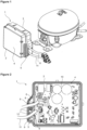
- the inverter board casing (1) of the present invention comprises a first cover (2); a second cover (3) which is mounted onto the first cover (2) such that the circuit board (10) and the cables (11) remain therebetween; a first receptacle (4) which is arranged on the base of the first cover (2) and which receives the circuit board (10); a second receptacle (5) which is adjacent to the first receptacle (4) and wherein the cables (11) extending from the circuit board (10) are borne; a first wall (6) where the second receptacle (5) is adjacent to the first receptacle (4); a second wall (7) which is disposed opposite to the first wall (6); and at least one slot-shaped first bearing and at least one slot-shaped second bearing (8 and 9) on each of the first and second walls (6 and 7), which extend in the vertical axis and which are inclined from top to bottom ( Figure 1 and Figure 2 ).
- the first and second bearings (8 and 9) on each wall (6 and 7) form a pair, and each pair of first and second bearings (8 and 9) provides the bearing and exit of only one cable (11) from the inverter board casing (1).
- a natural barrier is formed against the water inlet with the effect of gravity, and the cables (11) placed in the first and second bearings (8 and 9) prevent the water from entering the inverter board casing (1) as a support component to said barrier.
- the inverter board casing (1) comprises at least one first bearing (8) on the first wall (6) and at least one second bearing (9) on the second wall (7).
- the axes passing through the first and second bearings (8 and 9) are located in the same inclined direction.
- the walls of the first and second bearings (8 and 9) are located in the same direction.
- first and second bearings (8 and 9) parallel to each other.
- two cables (11) are allowed to enter/exit the inverter board casing (1).
- the inverter board casing (1) comprises at least one support (12) which extends upwards from the base of the second receptacle (5), which is in the form of a protrusion, which extends parallel to the first and second walls (6 and 7), and which supports from below the cables (11) placed in the first and second bearings (8 and 9).
- the upper short side of the second receptacle (5) is inclined from top to bottom.
- the flow rate of the water flowing over the outer surface of the inverter board casing (1) is reduced, and by means of the water path formed, the flowing water is transmitted to a further point from the second wall (7), thus minimizing the possibility of water entering through the second bearing (9) on the second wall (7).
- elements such as insects, water, etc. are prevented from entering the inverter board casing (1) from the outside and damaging the circuit board (10) or cable (11) connections. Moreover, the exit of the components such as cables (11) extending out of the inverter board casing (1) is not prevented.
Landscapes
- Engineering & Computer Science (AREA)
- Microelectronics & Electronic Packaging (AREA)
- Inverter Devices (AREA)
Abstract
Description
- The present invention relates to an inverter board casing which encloses the inverter board.
- The motor driver boards of the compressors used in cooling or air conditioning devices are kept in a separate plastic casing outside the compressor shell.
- In the state of the art, in order to prevent insects from entering the casings of the motor inverter boards and causing a short circuit on the circuit board, a coating process known in the art as "potting" is performed on the circuit board. In order for this process to be applied effectively, the first cover of the casing, which is formed by combining two covers, must be in the form of a pool. One of the limitations of the casing design is the prevention of water entry into the casing. Moreover, components extending out of the casing, such as cables, must not be blocked. In particular, the exit points of the cables extending out of the casing are the most likely points where water entry may occur. It is critical to prevent water from entering the casing through these points.
- The state of the art United States Patent No.
US5745343 , a motor and inverter casing of which the dimensions are reduced by using waste heat. - The state of the art Japanese Patent Application No.
JP2018182930 - The aim of the present invention is the realization of an inverter board casing wherein the exit of the components such as cables extending outside is not blocked and the water entry is prevented.
- The inverter board casing realized in order to attain the aim of the present invention, explicated in the first claim and the respective claims thereof, comprises a first cover; a second cover which is mounted onto the first cover such that the circuit board and the cables remain therebetween; a first receptacle which is arranged on the base of the first cover and which receives the circuit board; a second receptacle which is adjacent to the first receptacle and wherein the cables extending from the circuit board are borne; a first wall where the second receptacle is adjacent to the first receptacle; a second wall which is disposed opposite to the first wall; and at least one slot-shaped bearing on each of the first and second walls, which extends in the vertical axis and which is inclined from top to bottom.
- The bearings on each wall form a pair, and each pair of bearings provides the bearing and exit of only one cable from the inverter board casing. Since the bearings on the first wall are inclined from the first wall to the second wall, from top to bottom, and the bearings on the second wall are inclined outward from the second wall, from top to bottom, a natural barrier is formed against the water entry with the effect of gravity, and the cables placed in the bearings prevent the water from entering the inverter board casing as a support component to said barrier.
- By means of the bearings on the second receptacle in the inverter board casing, the water entry is prevented, and by means of the second receptacle, a pocket, so to speak, is formed in this area where the cables are located, thus creating an effective sealing zone against water entry.
- In an embodiment of the present invention, there are two first and second bearings parallel to each other. Thus, two cables are allowed to enter/exit the inverter board casing.
- In an embodiment of the present invention, the inverter board casing comprises at least one support which extends upwards from the base of the second receptacle, which is in the form of a protrusion, which extends parallel to the first and second walls, and which supports from below the cables placed in the first and second bearings.
- In another embodiment of the present invention, the first and second bearings are located in the same inclined direction. The central axis passing through the middle of the first and second bearings is on the same inclined direction, and thus the side walls of the slot-shaped bearings are also located in the same inclined direction.
- In another embodiment of the present invention, in the inverter board casing, the upper short side of the second receptacle is inclined from top to bottom. Thus, the flow rate of the water flowing over the outer surface of the inverter board casing is reduced, and by means of the water path formed, the flowing water is transmitted to a further point from the second wall, thus minimizing the possibility of water entering through the second bearing on the second wall.
- By means of the present invention, the exit of the components such as cables extending outside is not prevented, and elements such as insects, water, etc. are prevented from entering the inverter board casing from the outside and damaging the circuit board or connections.
- An inverter board casing realized in order to attain the aim of the present invention is illustrated in the attached figures, where:
-
Figure 1 - is the perspective view of an inverter board casing. -
Figure 2 - is the sideways view of the detail A inFigure 1 . - The elements illustrated in the figures are numbered as follows:
- 1. Inverter board casing
- 2. First cover
- 3. Second cover
- 4. First receptacle
- 5. Second receptacle
- 6. First wall
- 7. Second wall
- 8. First bearing
- 9. Second bearing
- 10. Circuit board
- 11. Cable
- 12. Support
- The inverter board casing (1) of the present invention comprises a first cover (2); a second cover (3) which is mounted onto the first cover (2) such that the circuit board (10) and the cables (11) remain therebetween; a first receptacle (4) which is arranged on the base of the first cover (2) and which receives the circuit board (10); a second receptacle (5) which is adjacent to the first receptacle (4) and wherein the cables (11) extending from the circuit board (10) are borne; a first wall (6) where the second receptacle (5) is adjacent to the first receptacle (4); a second wall (7) which is disposed opposite to the first wall (6); and at least one slot-shaped first bearing and at least one slot-shaped second bearing (8 and 9) on each of the first and second walls (6 and 7), which extend in the vertical axis and which are inclined from top to bottom (
Figure 1 and Figure 2 ). - The first and second bearings (8 and 9) on each wall (6 and 7) form a pair, and each pair of first and second bearings (8 and 9) provides the bearing and exit of only one cable (11) from the inverter board casing (1). By means of inclination of the first and second bearings (8 and 9) from top to bottom, a natural barrier is formed against the water inlet with the effect of gravity, and the cables (11) placed in the first and second bearings (8 and 9) prevent the water from entering the inverter board casing (1) as a support component to said barrier. By means of the first and second bearings (8 and 9) on the second receptacle (5) in the inverter board casing (1), the water entry is prevented, and by means of the second receptacle (5), a pocket, so to speak, is formed in this area where the cables (11) are located, thus creating an effective sealing zone against water entry.
- In an embodiment of the present invention, the inverter board casing (1) comprises at least one first bearing (8) on the first wall (6) and at least one second bearing (9) on the second wall (7).
- In another embodiment of the present invention, the axes passing through the first and second bearings (8 and 9) are located in the same inclined direction. In this embodiment, the walls of the first and second bearings (8 and 9) are located in the same direction.
- In an embodiment of the present invention, there are two first and second bearings (8 and 9) parallel to each other. Thus, two cables (11) are allowed to enter/exit the inverter board casing (1).
- In an embodiment of the present invention, the inverter board casing (1) comprises at least one support (12) which extends upwards from the base of the second receptacle (5), which is in the form of a protrusion, which extends parallel to the first and second walls (6 and 7), and which supports from below the cables (11) placed in the first and second bearings (8 and 9). In the preferred embodiment of the present invention, there are two supports (12) which are parallel to each other.
- In another embodiment of the present invention, in the inverter board casing (1), the upper short side of the second receptacle (5) is inclined from top to bottom. Thus, the flow rate of the water flowing over the outer surface of the inverter board casing (1) is reduced, and by means of the water path formed, the flowing water is transmitted to a further point from the second wall (7), thus minimizing the possibility of water entering through the second bearing (9) on the second wall (7).
- By means of the present invention, elements such as insects, water, etc. are prevented from entering the inverter board casing (1) from the outside and damaging the circuit board (10) or cable (11) connections. Moreover, the exit of the components such as cables (11) extending out of the inverter board casing (1) is not prevented.
Claims (6)
- An inverter board casing (1) comprising a first cover (2) and a second cover (3) which is mounted onto the first cover (2) such that the circuit board (10) and the cables (11) remain therebetween, characterized by a first receptacle (4) which is arranged on the base of the first cover (2) and which receives the circuit board (10); a second receptacle (5) which is adjacent to the first receptacle (4) and wherein the cables (11) extending from the circuit board (10) are borne; a first wall (6) where the second receptacle (5) is adjacent to the first receptacle (4); a second wall (7) which is disposed opposite to the first wall (6); and at least one slot-shaped first bearing and at least one slot-shaped second bearing (8 and 9) on each of the first and second walls (6 and 7), which extend in the vertical axis and which are inclined from top to bottom.
- An inverter board casing (1) as in Claim 1, characterized by at least one first bearing (8) on the first wall (6) and at least one second bearing (9) on the second wall (7).
- An inverter board casing (1) as in Claim 1 and 2, characterized by the first and second bearings (8 and 9) wherein the axes passing therethrough the center are located in the same inclined direction.
- An inverter board casing (1) as in Claim 1, 2 and 3, characterized by two first and second bearings (8 and 9) which are parallel to each other.
- An inverter board casing (1) as in any one of the above claims, characterized by at least one support (12) which extends upwards from the base of the second receptacle (5), which is in the form of a protrusion, which extends parallel to the first and second walls (6 and 7), and which supports from below the cables (11) placed in the first and second bearings (8 and 9).
- An inverter board casing (1) as in any one of the above claims, characterized by the second receptacle (5) of which the upper short side is inclined from top to bottom.
Applications Claiming Priority (1)
| Application Number | Priority Date | Filing Date | Title |
|---|---|---|---|
| TR202119242 | 2021-12-07 |
Publications (2)
| Publication Number | Publication Date |
|---|---|
| EP4195891A1 true EP4195891A1 (en) | 2023-06-14 |
| EP4195891B1 EP4195891B1 (en) | 2024-06-26 |
Family
ID=83546720
Family Applications (1)
| Application Number | Title | Priority Date | Filing Date |
|---|---|---|---|
| EP22199107.8A Active EP4195891B1 (en) | 2021-12-07 | 2022-09-30 | An inverter board casing |
Country Status (2)
| Country | Link |
|---|---|
| EP (1) | EP4195891B1 (en) |
| PL (1) | PL4195891T3 (en) |
Citations (5)
| Publication number | Priority date | Publication date | Assignee | Title |
|---|---|---|---|---|
| US5745343A (en) | 1994-11-11 | 1998-04-28 | Fanuc, Ltd. | Cubicle for inverter |
| TW201230573A (en) * | 2010-08-30 | 2012-07-16 | Hosiden Corp | Terminal box |
| CN108307596A (en) * | 2017-01-13 | 2018-07-20 | 光宝电子(广州)有限公司 | Shell, the electronic module with the shell and its manufacturing method |
| JP2018182930A (en) | 2017-04-14 | 2018-11-15 | アイシン精機株式会社 | Inverter and motor driver unit |
| CN208900853U (en) * | 2018-08-17 | 2019-05-24 | 山西建筑工程集团有限公司 | A kind of Cable Group casing water-tight device through walls |
-
2022
- 2022-09-30 EP EP22199107.8A patent/EP4195891B1/en active Active
- 2022-09-30 PL PL22199107.8T patent/PL4195891T3/en unknown
Patent Citations (5)
| Publication number | Priority date | Publication date | Assignee | Title |
|---|---|---|---|---|
| US5745343A (en) | 1994-11-11 | 1998-04-28 | Fanuc, Ltd. | Cubicle for inverter |
| TW201230573A (en) * | 2010-08-30 | 2012-07-16 | Hosiden Corp | Terminal box |
| CN108307596A (en) * | 2017-01-13 | 2018-07-20 | 光宝电子(广州)有限公司 | Shell, the electronic module with the shell and its manufacturing method |
| JP2018182930A (en) | 2017-04-14 | 2018-11-15 | アイシン精機株式会社 | Inverter and motor driver unit |
| CN208900853U (en) * | 2018-08-17 | 2019-05-24 | 山西建筑工程集团有限公司 | A kind of Cable Group casing water-tight device through walls |
Also Published As
| Publication number | Publication date |
|---|---|
| PL4195891T3 (en) | 2024-11-04 |
| EP4195891B1 (en) | 2024-06-26 |
Similar Documents
| Publication | Publication Date | Title |
|---|---|---|
| KR100995432B1 (en) | Outdoor unit of air conditioner | |
| EP1285877B1 (en) | Elevator control device | |
| KR20150025755A (en) | Apparatus for cooling inverter | |
| JP2014240727A (en) | Outdoor unit | |
| EP3147579B1 (en) | Outdoor equipment for refrigeration cycle device | |
| JP2005184921A (en) | Motor housing | |
| JP2016149841A (en) | Charger | |
| EP0673066A1 (en) | Heat sink | |
| EP4195891B1 (en) | An inverter board casing | |
| JP6225034B2 (en) | Sound inlet / outlet structure of soundproof box | |
| CN110382964A (en) | Heat source unit of refrigeration plant | |
| CN103003569B (en) | Oil for screw compressor rocks attenuating device | |
| CN101087979B (en) | Outdoor unit of air conditioner | |
| JP2006522302A (en) | Recooling equipment | |
| JP7086275B2 (en) | Outdoor unit of air conditioner | |
| EP1324464A1 (en) | Anticondensation device particularly for electric motors | |
| US7423872B2 (en) | Air shroud installed on a circuit board | |
| US20020100579A1 (en) | Cooling an apparatus cabinet | |
| CN107866693A (en) | Cooling device | |
| JP6830821B2 (en) | refrigerator | |
| TR2021019242A2 (en) | ONE INVERTER CARD BOX | |
| JPWO2020084681A1 (en) | Outdoor unit of air conditioner | |
| JP3206348B2 (en) | Outdoor unit of air conditioner | |
| JP7738781B1 (en) | Motor drive unit | |
| KR101485596B1 (en) | Outdoor unit of air conditioner |
Legal Events
| Date | Code | Title | Description |
|---|---|---|---|
| PUAI | Public reference made under article 153(3) epc to a published international application that has entered the european phase |
Free format text: ORIGINAL CODE: 0009012 |
|
| STAA | Information on the status of an ep patent application or granted ep patent |
Free format text: STATUS: REQUEST FOR EXAMINATION WAS MADE |
|
| 17P | Request for examination filed |
Effective date: 20220930 |
|
| AK | Designated contracting states |
Kind code of ref document: A1 Designated state(s): AL AT BE BG CH CY CZ DE DK EE ES FI FR GB GR HR HU IE IS IT LI LT LU LV MC MK MT NL NO PL PT RO RS SE SI SK SM TR |
|
| GRAP | Despatch of communication of intention to grant a patent |
Free format text: ORIGINAL CODE: EPIDOSNIGR1 |
|
| STAA | Information on the status of an ep patent application or granted ep patent |
Free format text: STATUS: GRANT OF PATENT IS INTENDED |
|
| INTG | Intention to grant announced |
Effective date: 20240328 |
|
| GRAS | Grant fee paid |
Free format text: ORIGINAL CODE: EPIDOSNIGR3 |
|
| GRAA | (expected) grant |
Free format text: ORIGINAL CODE: 0009210 |
|
| STAA | Information on the status of an ep patent application or granted ep patent |
Free format text: STATUS: THE PATENT HAS BEEN GRANTED |
|
| AK | Designated contracting states |
Kind code of ref document: B1 Designated state(s): AL AT BE BG CH CY CZ DE DK EE ES FI FR GB GR HR HU IE IS IT LI LT LU LV MC MK MT NL NO PL PT RO RS SE SI SK SM TR |
|
| REG | Reference to a national code |
Ref country code: GB Ref legal event code: FG4D |
|
| REG | Reference to a national code |
Ref country code: CH Ref legal event code: EP |
|
| REG | Reference to a national code |
Ref country code: DE Ref legal event code: R096 Ref document number: 602022004147 Country of ref document: DE |
|
| PG25 | Lapsed in a contracting state [announced via postgrant information from national office to epo] |
Ref country code: BG Free format text: LAPSE BECAUSE OF FAILURE TO SUBMIT A TRANSLATION OF THE DESCRIPTION OR TO PAY THE FEE WITHIN THE PRESCRIBED TIME-LIMIT Effective date: 20240626 |
|
| PG25 | Lapsed in a contracting state [announced via postgrant information from national office to epo] |
Ref country code: FI Free format text: LAPSE BECAUSE OF FAILURE TO SUBMIT A TRANSLATION OF THE DESCRIPTION OR TO PAY THE FEE WITHIN THE PRESCRIBED TIME-LIMIT Effective date: 20240626 Ref country code: HR Free format text: LAPSE BECAUSE OF FAILURE TO SUBMIT A TRANSLATION OF THE DESCRIPTION OR TO PAY THE FEE WITHIN THE PRESCRIBED TIME-LIMIT Effective date: 20240626 |
|
| REG | Reference to a national code |
Ref country code: LT Ref legal event code: MG9D |
|
| PG25 | Lapsed in a contracting state [announced via postgrant information from national office to epo] |
Ref country code: GR Free format text: LAPSE BECAUSE OF FAILURE TO SUBMIT A TRANSLATION OF THE DESCRIPTION OR TO PAY THE FEE WITHIN THE PRESCRIBED TIME-LIMIT Effective date: 20240927 |
|
| PG25 | Lapsed in a contracting state [announced via postgrant information from national office to epo] |
Ref country code: LV Free format text: LAPSE BECAUSE OF FAILURE TO SUBMIT A TRANSLATION OF THE DESCRIPTION OR TO PAY THE FEE WITHIN THE PRESCRIBED TIME-LIMIT Effective date: 20240626 |
|
| REG | Reference to a national code |
Ref country code: NL Ref legal event code: MP Effective date: 20240626 |
|
| PG25 | Lapsed in a contracting state [announced via postgrant information from national office to epo] |
Ref country code: NO Free format text: LAPSE BECAUSE OF FAILURE TO SUBMIT A TRANSLATION OF THE DESCRIPTION OR TO PAY THE FEE WITHIN THE PRESCRIBED TIME-LIMIT Effective date: 20240926 Ref country code: LV Free format text: LAPSE BECAUSE OF FAILURE TO SUBMIT A TRANSLATION OF THE DESCRIPTION OR TO PAY THE FEE WITHIN THE PRESCRIBED TIME-LIMIT Effective date: 20240626 Ref country code: HR Free format text: LAPSE BECAUSE OF FAILURE TO SUBMIT A TRANSLATION OF THE DESCRIPTION OR TO PAY THE FEE WITHIN THE PRESCRIBED TIME-LIMIT Effective date: 20240626 Ref country code: GR Free format text: LAPSE BECAUSE OF FAILURE TO SUBMIT A TRANSLATION OF THE DESCRIPTION OR TO PAY THE FEE WITHIN THE PRESCRIBED TIME-LIMIT Effective date: 20240927 Ref country code: FI Free format text: LAPSE BECAUSE OF FAILURE TO SUBMIT A TRANSLATION OF THE DESCRIPTION OR TO PAY THE FEE WITHIN THE PRESCRIBED TIME-LIMIT Effective date: 20240626 Ref country code: BG Free format text: LAPSE BECAUSE OF FAILURE TO SUBMIT A TRANSLATION OF THE DESCRIPTION OR TO PAY THE FEE WITHIN THE PRESCRIBED TIME-LIMIT Effective date: 20240626 Ref country code: RS Free format text: LAPSE BECAUSE OF FAILURE TO SUBMIT A TRANSLATION OF THE DESCRIPTION OR TO PAY THE FEE WITHIN THE PRESCRIBED TIME-LIMIT Effective date: 20240926 |
|
| PG25 | Lapsed in a contracting state [announced via postgrant information from national office to epo] |
Ref country code: NL Free format text: LAPSE BECAUSE OF FAILURE TO SUBMIT A TRANSLATION OF THE DESCRIPTION OR TO PAY THE FEE WITHIN THE PRESCRIBED TIME-LIMIT Effective date: 20240626 |
|
| REG | Reference to a national code |
Ref country code: AT Ref legal event code: MK05 Ref document number: 1698770 Country of ref document: AT Kind code of ref document: T Effective date: 20240626 |
|
| PG25 | Lapsed in a contracting state [announced via postgrant information from national office to epo] |
Ref country code: NL Free format text: LAPSE BECAUSE OF FAILURE TO SUBMIT A TRANSLATION OF THE DESCRIPTION OR TO PAY THE FEE WITHIN THE PRESCRIBED TIME-LIMIT Effective date: 20240626 |
|
| PG25 | Lapsed in a contracting state [announced via postgrant information from national office to epo] |
Ref country code: PT Free format text: LAPSE BECAUSE OF FAILURE TO SUBMIT A TRANSLATION OF THE DESCRIPTION OR TO PAY THE FEE WITHIN THE PRESCRIBED TIME-LIMIT Effective date: 20241028 |
|
| PG25 | Lapsed in a contracting state [announced via postgrant information from national office to epo] |
Ref country code: PT Free format text: LAPSE BECAUSE OF FAILURE TO SUBMIT A TRANSLATION OF THE DESCRIPTION OR TO PAY THE FEE WITHIN THE PRESCRIBED TIME-LIMIT Effective date: 20241028 |
|
| PG25 | Lapsed in a contracting state [announced via postgrant information from national office to epo] |
Ref country code: EE Free format text: LAPSE BECAUSE OF FAILURE TO SUBMIT A TRANSLATION OF THE DESCRIPTION OR TO PAY THE FEE WITHIN THE PRESCRIBED TIME-LIMIT Effective date: 20240626 |
|
| PG25 | Lapsed in a contracting state [announced via postgrant information from national office to epo] |
Ref country code: IS Free format text: LAPSE BECAUSE OF FAILURE TO SUBMIT A TRANSLATION OF THE DESCRIPTION OR TO PAY THE FEE WITHIN THE PRESCRIBED TIME-LIMIT Effective date: 20241026 Ref country code: AT Free format text: LAPSE BECAUSE OF FAILURE TO SUBMIT A TRANSLATION OF THE DESCRIPTION OR TO PAY THE FEE WITHIN THE PRESCRIBED TIME-LIMIT Effective date: 20240626 |
|
| PG25 | Lapsed in a contracting state [announced via postgrant information from national office to epo] |
Ref country code: CZ Free format text: LAPSE BECAUSE OF FAILURE TO SUBMIT A TRANSLATION OF THE DESCRIPTION OR TO PAY THE FEE WITHIN THE PRESCRIBED TIME-LIMIT Effective date: 20240626 |
|
| PG25 | Lapsed in a contracting state [announced via postgrant information from national office to epo] |
Ref country code: RO Free format text: LAPSE BECAUSE OF FAILURE TO SUBMIT A TRANSLATION OF THE DESCRIPTION OR TO PAY THE FEE WITHIN THE PRESCRIBED TIME-LIMIT Effective date: 20240626 Ref country code: SK Free format text: LAPSE BECAUSE OF FAILURE TO SUBMIT A TRANSLATION OF THE DESCRIPTION OR TO PAY THE FEE WITHIN THE PRESCRIBED TIME-LIMIT Effective date: 20240626 |
|
| PG25 | Lapsed in a contracting state [announced via postgrant information from national office to epo] |
Ref country code: ES Free format text: LAPSE BECAUSE OF FAILURE TO SUBMIT A TRANSLATION OF THE DESCRIPTION OR TO PAY THE FEE WITHIN THE PRESCRIBED TIME-LIMIT Effective date: 20240626 Ref country code: SM Free format text: LAPSE BECAUSE OF FAILURE TO SUBMIT A TRANSLATION OF THE DESCRIPTION OR TO PAY THE FEE WITHIN THE PRESCRIBED TIME-LIMIT Effective date: 20240626 |
|
| PG25 | Lapsed in a contracting state [announced via postgrant information from national office to epo] |
Ref country code: SM Free format text: LAPSE BECAUSE OF FAILURE TO SUBMIT A TRANSLATION OF THE DESCRIPTION OR TO PAY THE FEE WITHIN THE PRESCRIBED TIME-LIMIT Effective date: 20240626 Ref country code: SK Free format text: LAPSE BECAUSE OF FAILURE TO SUBMIT A TRANSLATION OF THE DESCRIPTION OR TO PAY THE FEE WITHIN THE PRESCRIBED TIME-LIMIT Effective date: 20240626 Ref country code: RO Free format text: LAPSE BECAUSE OF FAILURE TO SUBMIT A TRANSLATION OF THE DESCRIPTION OR TO PAY THE FEE WITHIN THE PRESCRIBED TIME-LIMIT Effective date: 20240626 Ref country code: IS Free format text: LAPSE BECAUSE OF FAILURE TO SUBMIT A TRANSLATION OF THE DESCRIPTION OR TO PAY THE FEE WITHIN THE PRESCRIBED TIME-LIMIT Effective date: 20241026 Ref country code: ES Free format text: LAPSE BECAUSE OF FAILURE TO SUBMIT A TRANSLATION OF THE DESCRIPTION OR TO PAY THE FEE WITHIN THE PRESCRIBED TIME-LIMIT Effective date: 20240626 Ref country code: EE Free format text: LAPSE BECAUSE OF FAILURE TO SUBMIT A TRANSLATION OF THE DESCRIPTION OR TO PAY THE FEE WITHIN THE PRESCRIBED TIME-LIMIT Effective date: 20240626 Ref country code: CZ Free format text: LAPSE BECAUSE OF FAILURE TO SUBMIT A TRANSLATION OF THE DESCRIPTION OR TO PAY THE FEE WITHIN THE PRESCRIBED TIME-LIMIT Effective date: 20240626 Ref country code: AT Free format text: LAPSE BECAUSE OF FAILURE TO SUBMIT A TRANSLATION OF THE DESCRIPTION OR TO PAY THE FEE WITHIN THE PRESCRIBED TIME-LIMIT Effective date: 20240626 |
|
| PG25 | Lapsed in a contracting state [announced via postgrant information from national office to epo] |
Ref country code: IT Free format text: LAPSE BECAUSE OF FAILURE TO SUBMIT A TRANSLATION OF THE DESCRIPTION OR TO PAY THE FEE WITHIN THE PRESCRIBED TIME-LIMIT Effective date: 20240626 |
|
| REG | Reference to a national code |
Ref country code: DE Ref legal event code: R097 Ref document number: 602022004147 Country of ref document: DE |
|
| REG | Reference to a national code |
Ref country code: DE Ref legal event code: R119 Ref document number: 602022004147 Country of ref document: DE |
|
| PG25 | Lapsed in a contracting state [announced via postgrant information from national office to epo] |
Ref country code: DK Free format text: LAPSE BECAUSE OF FAILURE TO SUBMIT A TRANSLATION OF THE DESCRIPTION OR TO PAY THE FEE WITHIN THE PRESCRIBED TIME-LIMIT Effective date: 20240626 |
|
| PG25 | Lapsed in a contracting state [announced via postgrant information from national office to epo] |
Ref country code: MC Free format text: LAPSE BECAUSE OF FAILURE TO SUBMIT A TRANSLATION OF THE DESCRIPTION OR TO PAY THE FEE WITHIN THE PRESCRIBED TIME-LIMIT Effective date: 20240626 |
|
| PLBE | No opposition filed within time limit |
Free format text: ORIGINAL CODE: 0009261 |
|
| STAA | Information on the status of an ep patent application or granted ep patent |
Free format text: STATUS: NO OPPOSITION FILED WITHIN TIME LIMIT |
|
| PG25 | Lapsed in a contracting state [announced via postgrant information from national office to epo] |
Ref country code: LU Free format text: LAPSE BECAUSE OF NON-PAYMENT OF DUE FEES Effective date: 20240930 |
|
| 26N | No opposition filed |
Effective date: 20250327 |
|
| PG25 | Lapsed in a contracting state [announced via postgrant information from national office to epo] |
Ref country code: DE Free format text: LAPSE BECAUSE OF NON-PAYMENT OF DUE FEES Effective date: 20250401 |
|
| REG | Reference to a national code |
Ref country code: BE Ref legal event code: MM Effective date: 20240930 |
|
| PG25 | Lapsed in a contracting state [announced via postgrant information from national office to epo] |
Ref country code: BE Free format text: LAPSE BECAUSE OF NON-PAYMENT OF DUE FEES Effective date: 20240930 |
|
| PG25 | Lapsed in a contracting state [announced via postgrant information from national office to epo] |
Ref country code: FR Free format text: LAPSE BECAUSE OF NON-PAYMENT OF DUE FEES Effective date: 20240930 |
|
| PG25 | Lapsed in a contracting state [announced via postgrant information from national office to epo] |
Ref country code: IE Free format text: LAPSE BECAUSE OF NON-PAYMENT OF DUE FEES Effective date: 20240930 |
|
| PG25 | Lapsed in a contracting state [announced via postgrant information from national office to epo] |
Ref country code: SE Free format text: LAPSE BECAUSE OF FAILURE TO SUBMIT A TRANSLATION OF THE DESCRIPTION OR TO PAY THE FEE WITHIN THE PRESCRIBED TIME-LIMIT Effective date: 20240626 |
|
| PGFP | Annual fee paid to national office [announced via postgrant information from national office to epo] |
Ref country code: TR Payment date: 20250919 Year of fee payment: 4 Ref country code: PL Payment date: 20250923 Year of fee payment: 4 |
|
| PG25 | Lapsed in a contracting state [announced via postgrant information from national office to epo] |
Ref country code: CY Free format text: LAPSE BECAUSE OF FAILURE TO SUBMIT A TRANSLATION OF THE DESCRIPTION OR TO PAY THE FEE WITHIN THE PRESCRIBED TIME-LIMIT; INVALID AB INITIO Effective date: 20220930 |
|
| PG25 | Lapsed in a contracting state [announced via postgrant information from national office to epo] |
Ref country code: HU Free format text: LAPSE BECAUSE OF FAILURE TO SUBMIT A TRANSLATION OF THE DESCRIPTION OR TO PAY THE FEE WITHIN THE PRESCRIBED TIME-LIMIT; INVALID AB INITIO Effective date: 20220930 |
|
| REG | Reference to a national code |
Ref country code: CH Ref legal event code: H13 Free format text: ST27 STATUS EVENT CODE: U-0-0-H10-H13 (AS PROVIDED BY THE NATIONAL OFFICE) Effective date: 20260504 |
|
| PG25 | Lapsed in a contracting state [announced via postgrant information from national office to epo] |
Ref country code: SI Free format text: LAPSE BECAUSE OF FAILURE TO SUBMIT A TRANSLATION OF THE DESCRIPTION OR TO PAY THE FEE WITHIN THE PRESCRIBED TIME-LIMIT Effective date: 20240626 |
|
| PG25 | Lapsed in a contracting state [announced via postgrant information from national office to epo] |
Ref country code: LT Free format text: LAPSE BECAUSE OF FAILURE TO SUBMIT A TRANSLATION OF THE DESCRIPTION OR TO PAY THE FEE WITHIN THE PRESCRIBED TIME-LIMIT Effective date: 20240626 |
|
| PG25 | Lapsed in a contracting state [announced via postgrant information from national office to epo] |
Ref country code: CH Free format text: LAPSE BECAUSE OF NON-PAYMENT OF DUE FEES Effective date: 20250930 |