EP4195694A1 - Loudspeaker - Google Patents
Loudspeaker Download PDFInfo
- Publication number
- EP4195694A1 EP4195694A1 EP22169430.0A EP22169430A EP4195694A1 EP 4195694 A1 EP4195694 A1 EP 4195694A1 EP 22169430 A EP22169430 A EP 22169430A EP 4195694 A1 EP4195694 A1 EP 4195694A1
- Authority
- EP
- European Patent Office
- Prior art keywords
- voice coil
- coil assembly
- magnet
- diaphragm
- loudspeaker
- Prior art date
- Legal status (The legal status is an assumption and is not a legal conclusion. Google has not performed a legal analysis and makes no representation as to the accuracy of the status listed.)
- Granted
Links
Images




Classifications
-
- H—ELECTRICITY
- H04—ELECTRIC COMMUNICATION TECHNIQUE
- H04R—LOUDSPEAKERS, MICROPHONES, GRAMOPHONE PICK-UPS OR LIKE ACOUSTIC ELECTROMECHANICAL TRANSDUCERS; ELECTRIC HEARING AIDS; PUBLIC ADDRESS SYSTEMS
- H04R1/00—Details of transducers, loudspeakers or microphones
- H04R1/20—Arrangements for obtaining desired frequency or directional characteristics
- H04R1/22—Arrangements for obtaining desired frequency or directional characteristics for obtaining desired frequency characteristic only
- H04R1/24—Structural combinations of separate transducers or of two parts of the same transducer and responsive respectively to two or more frequency ranges
-
- H—ELECTRICITY
- H04—ELECTRIC COMMUNICATION TECHNIQUE
- H04R—LOUDSPEAKERS, MICROPHONES, GRAMOPHONE PICK-UPS OR LIKE ACOUSTIC ELECTROMECHANICAL TRANSDUCERS; ELECTRIC HEARING AIDS; PUBLIC ADDRESS SYSTEMS
- H04R9/00—Transducers of moving-coil, moving-strip, or moving-wire type
- H04R9/06—Loudspeakers
-
- H—ELECTRICITY
- H04—ELECTRIC COMMUNICATION TECHNIQUE
- H04R—LOUDSPEAKERS, MICROPHONES, GRAMOPHONE PICK-UPS OR LIKE ACOUSTIC ELECTROMECHANICAL TRANSDUCERS; ELECTRIC HEARING AIDS; PUBLIC ADDRESS SYSTEMS
- H04R1/00—Details of transducers, loudspeakers or microphones
- H04R1/20—Arrangements for obtaining desired frequency or directional characteristics
- H04R1/22—Arrangements for obtaining desired frequency or directional characteristics for obtaining desired frequency characteristic only
- H04R1/26—Spatial arrangements of separate transducers responsive to two or more frequency ranges
-
- H—ELECTRICITY
- H04—ELECTRIC COMMUNICATION TECHNIQUE
- H04R—LOUDSPEAKERS, MICROPHONES, GRAMOPHONE PICK-UPS OR LIKE ACOUSTIC ELECTROMECHANICAL TRANSDUCERS; ELECTRIC HEARING AIDS; PUBLIC ADDRESS SYSTEMS
- H04R7/00—Diaphragms for electromechanical transducers; Cones
- H04R7/02—Diaphragms for electromechanical transducers; Cones characterised by the construction
- H04R7/12—Non-planar diaphragms or cones
- H04R7/122—Non-planar diaphragms or cones comprising a plurality of sections or layers
-
- H—ELECTRICITY
- H04—ELECTRIC COMMUNICATION TECHNIQUE
- H04R—LOUDSPEAKERS, MICROPHONES, GRAMOPHONE PICK-UPS OR LIKE ACOUSTIC ELECTROMECHANICAL TRANSDUCERS; ELECTRIC HEARING AIDS; PUBLIC ADDRESS SYSTEMS
- H04R7/00—Diaphragms for electromechanical transducers; Cones
- H04R7/16—Mounting or tensioning of diaphragms or cones
- H04R7/18—Mounting or tensioning of diaphragms or cones at the periphery
-
- H—ELECTRICITY
- H04—ELECTRIC COMMUNICATION TECHNIQUE
- H04R—LOUDSPEAKERS, MICROPHONES, GRAMOPHONE PICK-UPS OR LIKE ACOUSTIC ELECTROMECHANICAL TRANSDUCERS; ELECTRIC HEARING AIDS; PUBLIC ADDRESS SYSTEMS
- H04R7/00—Diaphragms for electromechanical transducers; Cones
- H04R7/26—Damping by means acting directly on free portion of diaphragm or cone
-
- H—ELECTRICITY
- H04—ELECTRIC COMMUNICATION TECHNIQUE
- H04R—LOUDSPEAKERS, MICROPHONES, GRAMOPHONE PICK-UPS OR LIKE ACOUSTIC ELECTROMECHANICAL TRANSDUCERS; ELECTRIC HEARING AIDS; PUBLIC ADDRESS SYSTEMS
- H04R9/00—Transducers of moving-coil, moving-strip, or moving-wire type
- H04R9/02—Details
-
- H—ELECTRICITY
- H04—ELECTRIC COMMUNICATION TECHNIQUE
- H04R—LOUDSPEAKERS, MICROPHONES, GRAMOPHONE PICK-UPS OR LIKE ACOUSTIC ELECTROMECHANICAL TRANSDUCERS; ELECTRIC HEARING AIDS; PUBLIC ADDRESS SYSTEMS
- H04R9/00—Transducers of moving-coil, moving-strip, or moving-wire type
- H04R9/02—Details
- H04R9/025—Magnetic circuit
-
- H—ELECTRICITY
- H04—ELECTRIC COMMUNICATION TECHNIQUE
- H04R—LOUDSPEAKERS, MICROPHONES, GRAMOPHONE PICK-UPS OR LIKE ACOUSTIC ELECTROMECHANICAL TRANSDUCERS; ELECTRIC HEARING AIDS; PUBLIC ADDRESS SYSTEMS
- H04R9/00—Transducers of moving-coil, moving-strip, or moving-wire type
- H04R9/02—Details
- H04R9/04—Construction, mounting, or centering of coil
- H04R9/041—Centering
- H04R9/043—Inner suspension or damper, e.g. spider
-
- H—ELECTRICITY
- H04—ELECTRIC COMMUNICATION TECHNIQUE
- H04R—LOUDSPEAKERS, MICROPHONES, GRAMOPHONE PICK-UPS OR LIKE ACOUSTIC ELECTROMECHANICAL TRANSDUCERS; ELECTRIC HEARING AIDS; PUBLIC ADDRESS SYSTEMS
- H04R9/00—Transducers of moving-coil, moving-strip, or moving-wire type
- H04R9/06—Loudspeakers
- H04R9/063—Loudspeakers using a plurality of acoustic drivers
-
- H—ELECTRICITY
- H04—ELECTRIC COMMUNICATION TECHNIQUE
- H04R—LOUDSPEAKERS, MICROPHONES, GRAMOPHONE PICK-UPS OR LIKE ACOUSTIC ELECTROMECHANICAL TRANSDUCERS; ELECTRIC HEARING AIDS; PUBLIC ADDRESS SYSTEMS
- H04R2209/00—Details of transducers of the moving-coil, moving-strip, or moving-wire type covered by H04R9/00 but not provided for in any of its subgroups
- H04R2209/022—Aspects regarding the stray flux internal or external to the magnetic circuit, e.g. shielding, shape of magnetic circuit, flux compensation coils
-
- H—ELECTRICITY
- H04—ELECTRIC COMMUNICATION TECHNIQUE
- H04R—LOUDSPEAKERS, MICROPHONES, GRAMOPHONE PICK-UPS OR LIKE ACOUSTIC ELECTROMECHANICAL TRANSDUCERS; ELECTRIC HEARING AIDS; PUBLIC ADDRESS SYSTEMS
- H04R2209/00—Details of transducers of the moving-coil, moving-strip, or moving-wire type covered by H04R9/00 but not provided for in any of its subgroups
- H04R2209/026—Transducers having separately controllable opposing diaphragms, e.g. for ring-tone and voice
-
- H—ELECTRICITY
- H04—ELECTRIC COMMUNICATION TECHNIQUE
- H04R—LOUDSPEAKERS, MICROPHONES, GRAMOPHONE PICK-UPS OR LIKE ACOUSTIC ELECTROMECHANICAL TRANSDUCERS; ELECTRIC HEARING AIDS; PUBLIC ADDRESS SYSTEMS
- H04R2400/00—Loudspeakers
- H04R2400/11—Aspects regarding the frame of loudspeaker transducers
-
- H—ELECTRICITY
- H04—ELECTRIC COMMUNICATION TECHNIQUE
- H04R—LOUDSPEAKERS, MICROPHONES, GRAMOPHONE PICK-UPS OR LIKE ACOUSTIC ELECTROMECHANICAL TRANSDUCERS; ELECTRIC HEARING AIDS; PUBLIC ADDRESS SYSTEMS
- H04R2499/00—Aspects covered by H04R or H04S not otherwise provided for in their subgroups
- H04R2499/10—General applications
- H04R2499/13—Acoustic transducers and sound field adaptation in vehicles
Definitions
- the present application relates to the field of loudspeakers, in particular to the field of flat full-spectrum loudspeakers.
- Loudspeakers are widely used in various areas, for example in consumer products like radios, television sets, audio players, computers, mobile phones and electronic musical instruments, and commercial applications, for example sound reinforcement in theatres, concert halls, and public address systems. Furthermore, in vehicles, for example planes, ships and cars, loudspeakers are widely used.
- a loudspeaker may comprise a magnet, in particular a permanent magnet, a voice coil arranged in a magnetic field provided by the magnet, a diaphragm (also called membrane) coupled to the voice coil and elastically coupled via a suspension (also called surround) to a frame of the loudspeaker.
- the voice coil may be a coil of wire capable of moving axially in a cylindrical gap containing a concentrated magnetic field produced by the permanent magnet.
- a further flexible suspension commonly called a "spider” is provided that constrains the voice coil to move axially through the cylindrical magnetic gap.
- the combination of magnet and voice coil is also called drive unit or electromagnetic motor system.
- Arrangement and properties of the magnet and voice coil may affect characteristics of a loudspeaker. Characteristics of a loudspeaker may relate to efficiency, i.e. the sound power output divided by the electrical power input, sensitivity, i.e. the sound pressure level at for example 1W electrical input measured at 1 meter, linearity or frequency response, maximum acoustic output power, size and weight. Characteristics may be different for different frequencies, for example small loudspeakers may have lower efficiency at low frequencies than large loudspeakers.
- a plurality of loudspeakers may be arranged at different locations to provide adequate sound output for each occupant.
- loudspeakers may be arranged in the dashboard, doors, the ceiling, seats and headrests.
- a full-spectrum audio output may require large installation space; in particular the output of low bass frequencies may require large loudspeakers and large volumes.
- the installation space may be limited, in particular, the available installation depth may be small for loudspeakers for wall mounting or for loudspeakers for installation in vehicles, e.g. in doors, on the ceiling and in the dashboard.
- a loudspeaker as defined in the independent claim is provided.
- the dependent claims define embodiments of the invention.
- the present disclosure provides a loudspeaker comprising a diaphragm, a tubular voice coil assembly, a magnet assembly and a flexible suspension.
- the tubular voice coil assembly is coupled to the diaphragm.
- a longitudinal axis of the tubular voice coil assembly extends along a central axis of the loudspeaker.
- the magnet assembly provides an annular gap in which the voice coil assembly is arranged.
- a magnetic field produced by the magnet assembly may be present in the annular gap. For example, lines of magnetic flux may be radially directed in the annular gap.
- the annular gap of the magnet assembly is also called air gap or cylindrical magnetic gap.
- a longitudinal axis of the annular gap extends along the central axis of the loudspeaker.
- the flexible suspension which is commonly called “Spider"
- the flexible suspension has a disc shape and is configured to guide a movement of the voice coil assembly along the central axis of the loudspeaker.
- the flexible suspension extends substantially perpendicular to the central axis.
- the flexible suspension may be aligned coaxially with the voice coil.
- An inner diameter of the voice coil assembly is greater than or equal to an outer diameter of the flexible suspension.
- the flexible suspension may extend in an area between the central axis and an inner diameter of the voice coil only.
- the voice coil assembly may surround the flexible suspension, i.e. the flexible suspension is arranged within the voice coil assembly.
- low-profile designs for example loudspeaker designs with a height along the central axis of less than 10 or 20 mm, providing a flexible suspension (spider) outside the voice coil assembly may not be possible due to spatial restrictions.
- omitting the flexible suspension may limit the performance in low-frequency range, because of less control on the voice coil at high excursion. Without the flexible suspension, excursion control is performed by the surround only, but the surround is usually not effective at the center of the diaphragm.
- a flat low-profile design may be achieved while at the same time providing guidance and excursion control at or near the center of the diaphragm. As a result, high-performance may be achieved over a wide spectrum, including in particular at low frequencies.
- the voice coil assembly may comprise a tubular carrier and a coil of wire arranged on an outside of the carrier.
- An inner diameter of the carrier is greater than or equal to the outer diameter of the flexible suspension.
- the flexible suspension has a corrugated disk shape.
- the flexible suspension has the disc shape with concentric grooves and ridges.
- the flexible suspension may be made of a corrugated fabric disc which is impregnated with a stiffening resin.
- the flexible suspension may be made of other materials, for example plastics or rubber.
- the flexible suspension may have a disc shape with a central opening, i.e. the flexible suspension may have a shape of a washer. In other examples, the flexible suspension may have a shape of a disc without any opening.
- the flexible suspension may provide high flexibility in the direction of the central axis and may minimize instabilities and movements during excursion in the radial direction perpendicular to the central axis. I.e., the flexible suspension provides guidance in the direction of the central axis, for example for the voice coil or the diaphragm of the loudspeaker, and can avoid movements that are not in the direction of the central axis.
- the magnet assembly comprises a magnet and a magnetic piece.
- the magnet may be made of a magnetic material, i.e. the magnet may be a permanent magnet.
- the magnetic material of the magnetic piece may comprise any ferromagnetic material, for example iron, a cobalt, nickel or a combination thereof.
- the magnet comprises a ring magnet with an axial magnetization, i.e. the magnet may have a right hollow cylindrical shape with a ring shaped cross section.
- the magnet may have any other shape which may be rotationally symmetrical or non-rotationally symmetrical, for example an ellipsoid shape, a polygon shape, a curved shape, or a combination of straight and curved sections.
- a shape of an inner surface of the magnet may have the same shape as an outer surface of the magnet or the inner surface of the magnet and the outer surface and of the magnet may have different shapes, for example, the inner surface may have a circular shape and the outer surface may have a polygonal shape.
- the magnetization may be in the height direction, for example along an axis of rotational symmetry.
- a magnetic field e.g. B-field
- the magnet may have a right hollow cylindrical shape and the magnetic piece may have also right hollow cylindrical shape.
- the magnet may have a ring shaped cross section.
- the magnetic piece may also have a ring shaped cross section.
- the magnetic piece may be smaller than the magnet such that it can be inserted into the hollow space of the magnet.
- an inner diameter of the magnet is larger than an outer diameter of the voice coil assembly.
- the magnetic piece is at least partially arranged within the voice coil assembly.
- An outer edge of the flexible suspension is attached to the magnetic piece.
- the magnet may be a ring magnet arranged outside the voice coil assembly.
- the ring magnet may be magnetically coupled to the magnetic piece which is arranged within the voice coil assembly.
- the annular gap is created between the ring magnet and the magnetic piece.
- the magnetic piece may limit the inner edge of the annular gap and the ring magnet may limit the outer edge of the annular gap.
- the gap between the magnet and the magnetic piece may have a right hollow cylindrical shape.
- the gap may have a ring shaped cross section.
- the magnet, the magnetic piece and thus the gap may have any other appropriate shape, for example a right hollow cylindrical shape with a cross section having an inner and/or outer circumference in the shape of a polygon, an ellipse or a combination of straight and/or curved sections.
- a width of the gap may relate to the distance between the magnet and the magnetic piece.
- the air gap may have a width of a few millimeters, for example in a range of 1 to 5 millimeters.
- the height of the gap may be in a range of a few millimeters to a few centimeters, for example in a range of 10 to 50 millimeters.
- the voice coil assembly is arranged within the ring magnet. Within the voice coil assembly, the magnetic piece is arranged.
- the flexible suspension extends from the magnetic piece in an inwards radial direction.
- a central area of the flexible suspension may be attached at least partially to a central area of the diaphragm or a dust cap arranged at a central area of the diaphragm.
- the flexible suspension thus provides guidance to a central area of the diaphragm, i.e. the flexible suspension constrains the central area of the diaphragm to move axially along the central axis of the loudspeaker.
- the loudspeaker further comprises a support structure arranged within the voice coil assembly.
- An outer edge of the flexible suspension is attached to an inner circumference of the voice coil assembly and a central area of the flexible suspension is at least partially attached to the support structure.
- the support structure may be a core cap of the loudspeaker or a support coupled to the magnet assembly, for example to a pole piece or magnet of the magnet assembly arranged within the voice coil assembly.
- the support structure may be a part of a core cap of the loudspeaker, i.e. the support structure may be integrally formed with the core cap of the loudspeaker.
- the support structure may comprise an additional magnet, e.g.
- the flexible suspension may constrain the voice coil assembly and the diaphragm coupled to the voice coil assembly to move axially along the central axis of the loudspeaker.
- the loudspeaker further comprises a tubular carrier attached to the diaphragm and arranged coaxially to the voice coil assembly.
- the tubular carrier may be attached to the diaphragm at a central area of the diaphragm.
- An outer diameter of the tubular carrier is smaller than an inner diameter of the voice coil assembly.
- the flexible suspension may have a central hole or opening. An edge of the central hole is attached to an outer circumference of the tubular carrier.
- the flexible suspension may provide guidance for the diaphragm via the tubular carrier.
- the flexible suspension may constrain a central area of the diaphragm to move axially along the central axis of the loudspeaker.
- the tubular carrier may support homogeneous transmission of force from the flexible suspension to the diaphragm.
- the magnet assembly comprises a magnet and a magnetic piece.
- An outer diameter of the magnet is smaller than an inner diameter of the voice coil assembly, i.e. the magnet may be arranged within the voice coil assembly.
- the magnet may be a ring magnet or a disc magnet.
- the magnetic piece is at least partially arranged outside the voice coil assembly.
- An outer edge of the flexible suspension is attached to the magnet or a core cap coupled to the magnet.
- a central area of the flexible suspension may be attached to a central area of the diaphragm, for example directly or indirectly via a tubular carrier as described above.
- the loudspeaker may comprise more than one diaphragm. Therefore, in the following, the above mentioned voice coil assembly will be named first voice coil assembly and the above mentioned diaphragm will be named first diaphragm.
- the loudspeaker comprises a second diaphragm arranged coaxially to the first diaphragm, and a second voice coil assembly coupled to the second diaphragm.
- the first diaphragm has a central hole. A diameter of the central hole is larger than or equal to an outer diameter of the second diaphragm.
- the second diaphragm may be arranged within the central hole of the first diaphragm.
- the flexible suspension has a central hole also, and an edge of the central hole of the flexible suspension is attached to the first diaphragm.
- the edge of the central hole of the flexible suspension may essentially be arranged at an edge of them the central hole of the first diaphragm such that a central area of the first diaphragm is guided by the flexible suspension.
- the second diaphragm may be driven independent from the first diaphragm by the second voice coil assembly.
- the first diaphragm may be controlled tool generate audio signals in a low and mid-range, for example in the range below 200 Hz whereas the second diaphragm may be controlled tool generate audio signals in a high range above the low and mid-range.
- the magnet assembly may comprise a first part arranged outside the first voice coil assembly, a second part arranged between the first voice coil assembly and the second voice coil assembly, and a third part arranged inside the second voice coil assembly.
- a magnetic field generated by at least one magnet of the magnet assembly may be guided through the first part, second part and third part.
- the magnet assembly provides a common magnetic flux which may be used for driving the first voice coil as well as the second voice coil.
- the common magnetic flux may be generated by a single magnet. Required installation space and weight may be reduced.
- a surround may be provided which couples an outer circumference of the second diaphragm to the first diaphragm.
- the surround may be provided between the edge of the central hole of the first diaphragm and the outer circumference of the second diaphragm to provide support at the outer circumference of the second diaphragm while enabling the first and second diaphragms to oscillate independently.
- the magnet assembly comprises a split gap core coupled to a magnet of the magnet assembly.
- the split gap core provides in an axial direction of the gap a varying magnetic field with two maxima.
- the split gap core may be configured such that in the direction of the central axis of the loudspeaker two annular gaps are provided. In each of the two annular gaps the magnetic flux is directed in a radial direction. In a first annular gap of the two annular gaps the magnetic flux may be directed outward, and in a second annular gap of the two annular gaps the magnetic flux may be directed inward.
- the magnetic flux in each of the two annular gaps may be provided by a common magnet of the magnet assembly.
- the voice coil assembly extends through each of the two annular gaps.
- the voice coil assembly comprises a first coil of wire with a first direction of winding and a second coil of wire with a second direction of winding opposite to the first direction of winding.
- the first coil of wire may be arranged at least partially in the first annular gap
- the second coil of wire may be arranged at least partially in the second annular gap.
- a common driving current may be conducted through the first and second coils of wire.
- the loudspeaker may comprise a basket or frame coupled to the magnet assembly, and a surround coupling an outer circumference of the diaphragm to the basket.
- the basket may be made of plastics or metal, e.g. aluminum, and may provide supports for mounting the loudspeaker at the place of installation, for example in a door or ceiling of a car or in a housing of a wall mounted speaker system.
- the surround may be made of elastic materials, for example rubber or plastics
- the loudspeaker may comprise two diaphragms arranged such that they emit sound in opposite directions.
- the above described diaphragm may be considered as a first diaphragm
- the above described the tubular voice coil assembly may be considered as a first tubular voice coil assembly coupled to the first diaphragm.
- the loudspeaker additionally comprises a second diaphragm spaced from the first diaphragm, and a second tubular voice coil assembly coupled to the second diaphragm.
- the magnet assembly comprises a magnet, a magnetic piece and a spacer.
- the spacer is made of non-magnetic material and connects the magnet and the magnetic piece such that a gap is provided between the magnet and the magnetic piece.
- the first voice coil assembly is arranged at a first end of the gap and the second voice coil assembly is arranged at a second end of the gap opposite the first end of the gap.
- two voice coils in connection with two diaphragms may be driven in corresponding magnetic fields, wherein these magnetic fields are created by a single magnet assembly, comprising in particular a single magnet only.
- the loudspeaker may have a compact and light weight design and may require small installation space while providing high efficiency and high power output due to the two driven diaphragms.
- a main direction of sound radiation of the first diaphragm and a main direction of sound radiation of the second diaphragm may be oppositely directed.
- the above described flexible suspension may be considered as a first flexible suspension
- the loudspeaker may comprise a further second flexible suspension coupled to the second voice coil assembly.
- the second flexible suspension has a disc shape and is configured to guide a movement of the second voice coil assembly along the central axis of the loudspeaker.
- the second flexible suspension extends substantially perpendicular to the central axis.
- An inner diameter of the second voice coil assembly is greater than or equal to an outer diameter of the second flexible suspension.
- the second flexible suspension may be arranged within the second voice coil assembly. In this way, a low-profile compact design may be achieved even with two opposing diaphragms.
- An outer edge of the first flexible suspension may be fixed to a first base of the magnetic piece, and an outer edge of the second flexible suspension may be fixed to a second base of the magnetic piece opposite to the first base of the magnetic piece.
- a center of the first flexible suspension may be coupled to a center of the first diaphragm, and a center of the second flexible suspension may be coupled to a center of the second diaphragm. Reliable guidance and control of the first and second diaphragms may be achieved.
- the loudspeaker may comprise optionally a first tubular carrier and optionally a second tubular carrier. If present, the first tubular carrier is attached to the first diaphragm and arranged coaxially to the first voice coil assembly. An outer diameter of the first tubular carrier is smaller than an inner diameter of the first voice coil assembly.
- the first flexible suspension may have a central opening. An edge of the central opening is attached to an outer circumference of the first tubular carrier. If present, the second tubular carrier is attached to the second diaphragm and arranged coaxially to the second voice coil assembly. An outer diameter of the second tubular carrier is smaller than an inner diameter of the second voice coil assembly.
- the second flexible suspension may have a central opening. An edge of the central opening is attached to an outer circumference of the second tubular carrier.
- the first and second tubular carriers may provide additional stiffness for the corresponding first and second diaphragms. Force transfer from the first and second flexible suspensions to the first and second diaphragms can be supported.
- Some examples of the present disclosure generally provide for a plurality of mechanical and electrical components. All references to the components and the functionality provided by each are not intended to be limited to encompassing only what is illustrated and described herein. While particular labels may be assigned to the various components disclosed, such labels are not intended to limit the scope of operation for the components. Such components may be combined with each other and/or separated in any manner based on the particular type of implementation that is desired. Same reference signs in the various drawings may refer to similar or identical components.
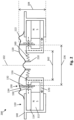
- FIG. 1 shows a sectional view a loudspeaker 100.
- the sectional view is taken along a central axis 102 of the loudspeaker 100.
- Several of the below described components may have an axis of rotational symmetry, for example circular or tubular components, and the axis of rotational symmetry of such components may be aligned to the central axis 102.
- the loudspeaker 100 comprises a magnet assembly 110, a diaphragm 120, a tubular voice coil assembly 130, and a flexible suspension 160.
- the loudspeaker 100 may furthermore comprise a chassis or basket 140 which supports the magnet assembly 110 and the diaphragm 120.
- the magnet assembly 110 may be glued to the basket 140 or supported by the basket 140 by press fitting.
- the basket 140 may be made of a rigid material, for example plastics or aluminum.
- the diaphragm 120 is coupled to the basket 140 via a surround 122 which provides a flexible support of the diaphragm 120 with respect to the basket 140 such that the diaphragm 120 is movable in at least the direction of the central axis 102.
- the surround 122 may enable a movement of the diaphragm back and forth in the direction of the central axis 102 and may restore the diaphragm 120 into a rest position after excursion.
- the surround 122 may be made of elastic material, for example rubber or plastics.
- An outer circumference of the diaphragm 120 may be circular such that an axis of rotational symmetry of the diaphragm 120 may be aligned to the central axis 102.
- the outer circumference of the diaphragm 120 may have any other shape, for example an oval or elliptical shape or a polygonal shape. Nevertheless, a center of the diaphragm 120 may be aligned to the central axis 102 of the loudspeaker 100.
- the diaphragm 120 may be made of paper, plastic, metal or a combination thereof. Other materials may be used. In particular, the material may be rigid to prevent uncontrolled motions, and may have a low mass to minimize starting force issues and may be well damped to reduce vibrations continuing after being deflected and to avoid resonance.
- the diaphragm 120 has a cone shape with an apex directing downwards, i.e. into an opening of the annular magnet assembly 110.
- the diaphragm 120 may have any other shape, for example a dome shape or a spherical shape.
- the magnet assembly 110 provides an annular gap 150 in which the voice coil assembly 130 is arranged without contacting the magnet assembly 110.
- a longitudinal axis of the annular gap 150 extends along the central axis 102 of the loudspeaker 100.
- the magnet assembly 110 comprises a permanent magnet 112, a first magnetic piece 114 and a second magnetic piece 116.
- the magnet 112 may comprise ferromagnetic material, for example iron, nickel, cobalt and/or neodymium.
- the magnet 112 may be a ring magnet having an axis of rotational symmetry aligned to the central axis 102.
- the magnet 112 may have, at one end in the direction of the central axis 102, a first magnetic pole, for example a north pole N, and at another end opposing to the one end in the direction of the central axis 102 a second magnetic pole, for example a south pole S.
- the first and second magnetic pieces 114, 116 may be made of ferromagnetic material, for example iron, nickel or cobalt.
- the first magnetic piece 114 may have a ring or washer shape and the second magnetic piece 116 may have a ring shape with an L-shaped or J-shaped cross-section such that the annular gap 150 is formed between an edge of the first magnetic piece 114 and an edge of the second magnetic piece 116.
- a magnetic flux 170 from the magnet 112 may be concentrated in the annular gap 150.
- the tubular voice coil assembly 130 is arranged such that an axis of rotational symmetry of the voice coil assembly 130 is aligned to the central axis 102.
- the voice coil assembly 130 extends at least partially within the annular gap 150.
- the tubular voice coil assembly 130 is coupled to the diaphragm 120, for example by gluing.
- the voice coil assembly 130 is coupled to the diaphragm 120 in an outer area of the diaphragm 120.
- the voice coil assembly 130 may be coupled to the diaphragm 120 in a more inner area of the diaphragm 120.
- the voice coil assembly 130 may comprise a tubular carrier 132 and a coil of wire 134 arranged on an outside of the carrier 132.
- the carrier 132 may be made of a non-magnetic material, for example paper, aluminum or plastics, like polyimide, for example Kapton.
- the coil of wire 134 Upon energizing the coil of wire 134 with electrical energy, the coil of wire 134 generates a magnetic field which interacts with the magnetic field within the annular gap 150 such that the voice coil assembly 130 is urged in the direction of the central axis 102.
- the amount and direction of movement of the voice coil assembly 130 may be controlled.
- the voice coil assembly 130 is essentially moved only in the direction of the central axis 102 to avoid contact between the voice coil assembly 130 and the magnetic pieces 114 and 116 and to achieve linearity.
- the flexible suspension 160 is provided.
- the flexible suspension 160 commonly called “spider”, has a corrugated disc shape. I.e., the flexible suspension 160 may have a waveform in the radial direction.
- the flexible suspension 160 may be made of a fabric.
- the flexible suspension 160 may comprise a fiber reinforced material comprising for example cotton, silk, aramid fibers, plastics, carbon fibers, glass fibers, resin or rubber.
- a central area of the flexible suspension 160 is coupled to the apex or a central area of the diaphragm 120.
- An outer circumference of the flexible suspension 160 is coupled to the second magnetic piece 116, for example at an inner circumference of the second magnetic piece 116.
- the flexible suspension 160 may be glued to the second magnetic piece 116.
- the flexible suspension 160 constrains at least the central area of the diaphragm 120 to move substantially in the direction of the central axis 102.
- the rigidity of the diaphragm 120 traverses the guidance from the flexible suspension 160 to the voice coil assembly 130 such that the flexible suspension 160 at least indirectly constrains the voice coil assembly 113 to move along the central axis 102 of the loudspeaker 100.
- the flexible suspension 160 allows the voice coil assembly 130 to move substantially only along the central axis 102.
- the flexible suspension 160 may be directly coupled to the voice coil assembly 130.
- an inner diameter 136 of the voice coil assembly 130 is greater than an outer diameter 162 of the flexible suspension 160.
- the flexible suspension 160 extends between the central axis 102 and a part of the second magnetic piece 116 which is arranged within the voice coil assembly 130.
- Arranging the flexible suspension 160 within the voice coil assembly 130 enables a flat design of the loudspeaker 100, i.e. a height 104 of the loudspeaker 100 in the direction of the central axis 102 may become small.
- a loudspeaker as shown in FIG. 1 may have a height 104 of less than 20 or 50 mm with an outer diameter of the diaphragm 120 in a range of 150 to 300 mm. Height 104 may be much less than 20mm, e.g. 10 mm.
- the flexible suspension 160 may provide guidance in the direction of the central axis 102.
- the flexible suspension 160 may inhibit or reduce a deflection of the diaphragm 120 in the lateral direction, i.e. in a radial direction perpendicular to the central axis 102.
- the flexible suspension 160 enables deflection in the direction of the central axis 102 and provides a restoring force to a rest position for the diaphragm 120 and the voice coil assembly 130.
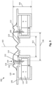
- FIG. 2 illustrates a further loudspeaker 200 with a similar structure as the loudspeaker 100 shown in FIG. 1 .
- the basket 140, the magnet assembly 110 and the voice coil 130 have essentially the same structure as the corresponding components of the loudspeaker 100 of FIG. 1 .
- the loudspeaker 200 of FIG. 2 differs from the loudspeaker 100 of FIG. 1 at least in the shape of the diaphragm 120, the flexible suspension 160 and the connection between these components.
- a tubular carrier 210 is provided which may be aligned to the central axis 102 of the loudspeaker 200.
- the tubular carrier 210 is arranged coaxially to the voice coil assembly 130.
- An outer diameter of the tubular carrier 210 is smaller than the inner diameter of the voice coil assembly 130, i.e. the tubular carrier 210 is arranged within the voice coil assembly 130.
- the tubular carrier 210 is also arranged within the second magnetic piece 116.
- a base of the tubular carrier 120 is mounted at the diaphragm 120, for example by gluing.
- the flexible suspension 160 has a disc shape with a central opening, i.e. the flexible suspension 160 has a washer shape.
- the outer diameter of the tubular carrier 210 may correspond to the diameter of the central opening of the flexible suspension 160.
- the edge of the central opening of the flexible suspension 160 may be mounted at the outer circumference of the tubular carrier 210, for example by gluing or press fitting.
- the tubular carrier may be made of a rigid material, for example plastics or aluminum.
- the washer shaped flexible suspension 160 may have a corrugated cross-section in the radial direction. An outer edge of the flexible suspension 160 may be mounted at the second magnetic piece 116. As a result, the flexible suspension 160 constrains the tubular carrier 210 to move essentially only in the direction of the central axis 102, but not in any direction perpendicular to the direction of the central axis 102. Due to the rigidity of the carrier 210, additional stiffness may be provided for the diaphragm 120. Stiffness of the diaphragm 120 may further be increased by the shape of the diaphragm 120 in the radial direction, for example, as shown in FIG. 2 , by providing an arched surface in the contact area with the tubular support 210.
- a reliable guidance of the voice coil assembly 130 within the gap 150 is provided such that the voice coil assembly 130 can move essentially in the up and down direction along the central axis 102 only.
- a flat loudspeaker design may be achieved by arranging the flexible suspension 160 within the voice coil assembly 130, while at the same time achieving reliable guidance and control of the diaphragm 120 and the voice coil assembly 130.
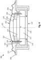
- FIG. 3 shows a further loudspeaker 300 which corresponds, at least to a large extent, to the loudspeaker 200 shown in FIG. 2 .
- the loudspeaker 300 of FIG. 3 distinguishes from the loudspeaker 200 of FIG. 2 at least in that the loudspeaker 300 of FIG. 3 does not comprise the tubular support 210.
- the inner edge of the flexible suspension 160 i.e. the edge of the central opening of the flexible suspension 160, is directly coupled to a central area of the diaphragm 120.
- the flexible suspension 160 may have a corrugated cross-section in the radial direction and an outer edge of the flexible suspension 160 may be mounted at the second magnetic piece 116.
- the flexible suspension 160 constrains the diaphragm 120 together with the voice coil assembly 130 to move essentially in the direction of the central axis 102 only.
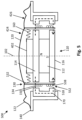
- FIG. 4 illustrates a further loudspeaker 400 comprising a magnet assembly 110, a diaphragm 120, a voice coil assembly 130 and a flexible suspension 160.
- the magnet 112 of the magnet assembly 110 of the loudspeaker 400 of FIG. 4 is arranged within the voice coil assembly 130.
- a first magnetic piece 114 and a second magnetic piece 116 guide the magnetic flux 170 from the magnet 112 through a gap 150 in which the voice coil assembly 130 is arranged.
- the magnet 112, the first magnetic piece 114 and the second magnetic piece 116 may each have an axis of rotational symmetry and may be each aligned to the central axis 102 of the loudspeaker 400.
- the magnet 112 may be a disc magnet with a first magnetic pole at a first base of the magnet 112 and an opposite second magnetic pole at an opposite second base of the magnet 112.
- the first magnetic piece 114 is arranged at the first base and the second magnetic piece 116 is arranged at the second base.
- the first magnetic piece 114 may have a disc shape
- the second magnetic piece 116 may have a shape with rotational symmetry and J- or L-cross-section along a radius.
- a support structure 402 is provided on a surface of the first magnetic piece 114 opposite to the surface with which the first magnetic piece 114 is in contact with the magnet 112.
- the support structure 402 may be made of non-magnetic material, for example a paramagnetic, diamagnetic, or anti-ferromagnetic material.
- the support structure 402 may be made of plastics or a non-magnetic metal like aluminum. In other examples, the support structure 402 may be made of ferromagnetic materials.
- the support structure 402 may have a disc shape. An axis of rotational symmetry of the support structure 402 may be aligned to the central axis 102.
- the support structure 402 may be a part of the first magnetic piece 114 of the loudspeaker 400, i.e., the support structure 402 may be integrally formed with the first magnetic piece 114.
- the support structure 402 may comprise an additional magnet, for example a ring-shaped or disc-shaped magnet, arranged on the magnet assembly 110 such that the polarities of the additional magnet (i.e. the support structure 402) and the magnet assembly 110 are opposite to each other.
- the diaphragm 120 may have a spherical shape with one radius in a central area 424 and another radius in a marginal area 426.
- the voice coil assembly 130 is mounted in the transition area between the central area 424 and the marginal area 426.
- the flexible suspension 160 has a washer shape with a central opening. An edge of the central opening of the flexible suspension 160 is mounted at the support structure 402, for example by gluing.
- the washer shaped flexible suspension 160 may have a corrugated cross-section in the radial direction.
- An outer circumference of the flexible suspension 160 may essentially correspond to an inner circumference of the carrier 132 of the voice coil assembly 130.
- the flexible suspension 160 is arranged within the voice coil assembly 130, in particular, the outer edge of the flexible suspension 160 is mounted at the inner surface of the carrier 132 of the voice coil assembly 130, for example by gluing.
- a compact design of the loudspeaker 400 may be achieved.
- a low height and a small diameter may be achieved, wherein the diameter is essentially dictated by the diameter of the diaphragm 120.
- FIG. 5 shows a further loudspeaker 500 with a magnet 112 being arranged within the voice coil assembly 130 as the loudspeaker 400 of FIG. 4 .
- the magnet assembly 110 of the loudspeaker 500 of FIG. 5 provides, besides the first annular gap 150, a second annular gap 552.
- the magnet assembly 110 comprises a disc shaped magnet 112, a disc shaped first magnetic piece 114 at one base of the magnet 112, a disc shaped second magnetic piece 116 at the other base of the magnet 112, and a third annular magnetic piece 518 surrounding the stack of the first magnetic piece 114, the magnet 112 and the second magnetic piece 116.
- a magnetic flux 170 from the magnet 112 is guided by the first magnetic piece 114 in an radial outward direction through the first gap 150 into the third magnetic piece 518 and from there through the second gap 552 into the second magnetic piece 116 and back to the magnet 112.
- the magnetic flux 170 of the magnet 112 is used twice, but must also bridge two air gaps 150, 552. Therefore, in this description, such magnet assembly 110 will be called "split gap core".
- the voice coil assembly 130 comprises a carrier 132 and a first coil of wire 134 and a second coil of wire 538.
- the first coil of wire 134 has a first direction of winding and the second coil of wire 538 has a second direction of winding which is opposite to the first direction of winding.
- the carrier 132 extends through the first gap 150 and the second gap 552.
- a current for driving the voice coil assembly 130 may be conducted through the first and second coils of wire 134 and 538 in series.
- the voice coil assembly 130 may be configured such that, in a rest position of the loudspeaker 500, the first coil of wire 134 is at least partially arranged within the first annular gap 150, and the second coil of wire 538 is at least partially arranged within the second annular gap 552.
- the split gap core in combination with this voice coil assembly 130 has a large symmetry and improved linearity, even at large excursion of the diaphragm 120.
- a support structure 402 is provided at the first magnetic piece 114.
- an edge of the central opening of the flexible suspension 160 is mounted.
- An outer circumference of the flexible suspension 160 is mounted at the inner circumference of the carrier 132 of the voice coil assembly 130.
- a further (not shown) flexible suspension may be provided at another height of the voice coil assembly 130 for additional guidance and support of the voice coil assembly 130.
- the further flexible suspension may have a washer shape.
- An edge of a central opening of the further flexible suspension may be mounted at the outer circumference of the magnet 112, and an outer circumference of the further flexible suspension may be mounted at the inner circumference of the carrier 132 of the voice coil assembly 130.
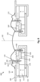
- the loudspeaker 600 comprises a magnet assembly 110, a first diaphragm 120, a second diaphragm 620, and a basket 140.
- the first diaphragm 120 has an annular shape such that the second diaphragm 620 may be arranged within an opening of the first diaphragm 120.
- An outer edge of the first diaphragm 120 is coupled via a first surround 122 to the basket 140.
- An outer edge of the second diaphragm 620 is coupled to an inner edge of the first diaphragm 120 via a second surround 622.
- a first voice coil assembly 130 is mounted at the first diaphragm 120, and a second voice coil assembly 630 is mounted at the second diaphragm 620. Structures of the first voice coil assembly 130 and the second voice coil assembly 630 may essentially correspond to the structure of the voice coil assembly 130 described above in connection with FIGs. 1 to 5 .
- the magnet assembly 110 provides a first annular gap 150 and a second annular gap 650.
- the magnet assembly 110 may comprise a magnet 112, a first magnetic piece 114, a second magnetic piece 116, and a magnetic interim piece 618.
- a spacer 660 may be provided between the magnetic interim piece 618 and the second magnetic piece 116 for supporting the magnetic interim piece 618.
- the spacer 660 may be made of non-magnetic material, for example a paramagnetic, diamagnetic, or antiferromagnetic material.
- the spacer 660 may be made of plastics or a non-magnetic metal like aluminum.
- the magnet assembly 110 may be configured such that the magnetic flux 170 from a first pole of the magnet 112, for example the north pole N, is guided subsequently through the first magnetic piece 114, the first annular gap 150, the magnetic interim piece 618, the second annular gap 650 and the second magnetic piece 116 to a second pole of the magnet 112, for example the south pole S.
- the first voice coil assembly 130 is arranged in the first annular gap 150.
- the second voice coil assembly 630 is arranged.
- the first voice coil assembly 130 drives the first diaphragm 120 and the second voice coil assembly 630 drives of the second diaphragm 620.
- the first and second diaphragms 120, 620 may be controlled independently.
- a first driving signal representing low frequencies may be supplied to the first voice coil assembly 130 for generating low-frequency audio output by the first diaphragm 120.
- a second driving signal representing high frequencies may be supplied to the second voice coil assembly 630 for generating high frequency audio output by the second diaphragm 620.
- audio signals in a wide frequency range may be output by the loudspeaker 600 which requires a single magnet 112 only and has a compact design.
- a flexible suspension 160 is provided within the first voice coil assembly 130.
- the flexible suspension 160 may have a corrugated disc shape with a central opening, i.e. the flexible suspension 160 may have a washer shape.
- an outer edge of the flexible suspension 160 may be coupled to the magnetic interim piece 618, and an inner edge of the flexible suspension 160 may be coupled to an inner edge of the first diaphragm 120.
- the flexible suspension 160 guides a movement of the first diaphragm 120 such that it constrains the first voice coil assembly 130 to move essentially in the direction of the central axis 102 only.
- the flexible suspension 160 also guides the movement of the second diaphragm 620 via the second surround 622 such that it constrains the second voice coil assembly 630 to move essentially in the direction of the central axis 102 only. As a result, a compact and in particular flat design of the loudspeaker 600 may be achieved.
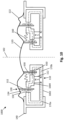
- FIG. 7 shows a further loudspeaker 700 with a similar structure as the loudspeaker 600 of FIG. 6 .
- the loudspeaker 700 of FIG. 7 comprises, in the magnet assembly 110, a second magnet 712.
- the second magnet 712 may have a disc or ring shape and is arranged within the second voice coil assembly 630.
- the second magnet 712 may be part of the second magnetic piece 116.
- the second magnetic piece 116 comprises a first part 116a and a second part 116b.
- the magnetic flux 170 of the magnets 112 and 712 may be conducted by the magnet assembly 110 as follows: the magnetic flux 170 from a first pole of the first magnet 112, for example a north pole N, is guided by the first magnetic piece 114 through the first gap 150 and further by the magnetic interim piece 618 through the second gap 650. Then, the magnetic flux 170 is guided by the first part 116a of the second magnetic piece 116 to a first pole of the second magnet 712.
- the first pole of the second magnet has a polarity opposite to the polarity of the first pole of the first magnet 112, for example a south pole S.
- the magnetic flux 170 is guided by the second part 116b of the second magnetic piece 116 from a second pole of the second magnet, for example a north pole N, to a second pole of the first magnet 112, for example a south pole S.
- the first and second magnets 112, 712 cooperate to generate the magnetic flux 170. In some implementations, this may increase the resulting magnetic flux 170 which may contribute to increase the output power of the loudspeaker 700.
- each of the first and second magnets 112, 712 may be made smaller thus reducing the installation space of the loudspeaker 700 without reducing the output power.
- FIG. 8 illustrates a further exemplary loudspeaker 800.
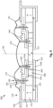
- the loudspeaker 800 comprises a magnet assembly 110, a diaphragm 120, a first tubular voice coil assembly 130 and a second tubular voice coil assembly 630 and a basket 140.
- the first voice coil assembly 130 has a larger diameter than the second voice coil assembly 630.
- the second voice coil assembly 630 is arranged within the first voice coil assembly 130.
- the first voice coil assembly and the second voice coil assembly are arranged coaxially and aligned to the central axis 102. Both, the first and second voice coil assemblies 130, 630 are mounted at the diaphragm 120.
- the first voice coil assembly 130 is mounted in an outer area of the diaphragm 120, whereas the second voice coil assembly 630 is mounted to the diaphragm 120 in an area between a center of the diaphragm 120 and the first voice coil assembly 130.
- the structures of the first voice coil assembly 130 and the second voice coil assembly 630 may essentially correspond to the structure of the voice coil assembly 130 described above in connection with FIGs. 1 to 5 .
- the magnet assembly 110 provides a first annular gap 150 and a second annular gap 650.
- the magnet assembly 110 may comprise a magnet 112, a first magnetic piece 114, a second magnetic piece 116, and a magnetic interim piece 618.
- the magnet assembly 110 is configured such that a magnetic flux 170 from a first pole of the magnet 112, for example the north pole N, is a guided subsequently through the first magnetic piece 114, the first annular gap 150, the magnetic interim piece 618, the second annular gap 650 and the second magnetic piece 116 to a second pole of the magnet 112, for example a south pole S.
- the first voice coil assembly 130 is arranged in the first annular gap 150
- the second voice coil assembly 630 is arranged in the second annular gap 650.
- the first and second voice coil assemblies 130, 630 commonly drive the diaphragm 120.
- a diaphragm 120 having a large diameter for example a diaphragm of a bass loudspeaker with a diameter of 150mm or more, may be efficiently driven by the two voice coil assemblies 130, 630, increasing for example output power and linearity, while at the same time providing a low-profile and lightweight design.
- a flexible suspension 160 is provided within the first voice coil assembly 130.
- the flexible suspension 160 may have a corrugated disc shape with a central opening, i.e. the flexible suspension 160 may have a washer shape.
- an outer edge of the flexible suspension 160 may be coupled to the magnetic interim piece 618, and an inner edge of the flexible suspension 160 may be coupled to the diaphragm 120, for example near the mounting of the second voice coil assembly 630.
- the flexible suspension 160 guides a movement of the diaphragm 120 such that it constrains the first voice coil assembly 130 to move essentially in the direction of the central axis 102 only.
- the flexible suspension 160 also constrains the second voice coil assembly 630 to move essentially in the direction of the central axis 102 only.
- a single flexible suspension 160 controls movement of both first and second voice coil assemblies 130, 630.
- the loudspeaker 900 illustrated in FIG. 9 has a similar structure as the loudspeaker 800 of FIG. 8 .
- the loudspeaker 900 of FIG. 9 comprises, in the magnet assembly 110, a second magnet 712.
- the second magnet 712 may have a disc or ring shape and is arranged within the second voice coil assembly 630.
- the second magnet 712 may be part of the second magnetic piece 116.
- the second magnetic piece 116 comprises a first part 116a and a second part 116b.
- the magnetic flux 170 within the magnet assembly 110 may be as follows: the magnetic flux 170 is guided by the first magnetic piece 114 from a first pole (for example a north pole N) of the first magnet 112 through the first gap 150 and further by the magnetic interim piece 618 through the second gap 650. Then, the magnetic flux 170 is guided by the first part 116a of the second magnetic piece 116 to a first pole (for example a south pole S) of the second magnet 712 which is opposite to the first pole of the first magnet 112. Finally, the magnetic flux 170 is guided by the second part 116b of the second magnetic piece 116 from a second pole of the second magnet (for example a north pole N) to a second pole of the first magnet 112 (for example a south pole S).
- the first and second magnets 112, 712 cooperate to generate the magnetic flux 170. In some implementations, this may increase the resulting magnetic flux 170 which may contribute to increase the output power of the loudspeaker 900. In other implementations, each of the first and second magnets 112, 712 may be made smaller thus reducing the installation space of the loudspeaker 900 without reducing the output power.
- FIG. 10 illustrates a further loudspeaker 1000 which has a similar structure as the loudspeakers 800 and 900 shown in FIGs. 8 and 9 .
- a substantial difference lies in the magnet assembly 110.
- the magnet assembly 110 comprises an enclosing magnetic piece 1002 extending from inside the second voice coil assembly 630 to an area outside the first voice coil assembly 130.
- the enclosing magnetic piece 1002 has a U-shaped cross-section in a radial direction.
- an interim magnetic piece 1004 is provided between the first voice coil assembly 130 and the second voice coil assembly 630.
- a first annular gap 150 is formed between one edge of the enclosing magnetic piece 1002 and one edge of the interim magnetic piece 1004.
- a second annular gap 650 is formed between another edge of the enclosing magnetic piece 1002 and another edge of the interim magnetic piece 1004.
- the first voice coil assembly 130 extends in the first annular gap 150 and the second voice coil assembly 630 extends in the second annular gap 650.
- a magnet 112, for example a ring magnet, is provided between the first voice coil assembly 130 and the second voice coil assembly 630.
- One base of the magnet 112 is in contact with the enclosing magnetic piece 1002 and another base of the magnet 112 is in contact with the interim magnetic piece 1004.
- Magnetic flux generated by the magnet 112 is guided by the enclosing magnetic piece 1002 and the interim magnetic piece 1004 as follows: a first part 170a of the magnetic flux is guided from a first pole of the magnet 112 (for example the north pole N) by the interim magnetic piece 1004 through the first annular gap 150 and further by one leg of the enclosing magnetic piece 1002 back to a second pole of the magnet 112 (for example the south pole S). A second part 170b of the magnetic flux is guided from the first pole of the magnet 112 by the interim magnetic piece through the second annular gap 650 and further by the other leg of the enclosing magnetic piece 1002 back to the second pole of the magnet 112.
- a first part 170a of the magnetic flux is guided from a first pole of the magnet 112 (for example the north pole N) by the interim magnetic piece 1004 through the first annular gap 150 and further by one leg of the enclosing magnetic piece 1002 back to a second pole of the magnet 112 (for example the south pole S).
- a single magnet provides magnetic flux for two separate annular gaps 150, 650.
- the two voice coil assemblies 130 and 630 which commonly drive the diaphragm 120, may increase total output power of the loudspeaker 1000 while achieving a compact and lightweight design.
- linearity of the loudspeaker 1000 may be improved, in particular in connection with a diaphragm 120 with a large diameter as required for low frequency output.
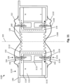
- FIG. 11 shows a loudspeaker 1100 including a magnet assembly 1110, a first diaphragm 120, a second diaphragm 1130 and a basket 140.
- the magnet assembly 1110, the first diaphragm 120, the second diaphragm 1130 and at least parts of the basket 140 may each have a rotationally symmetrical shape with an axis of rotational symmetry aligned to the longitudinal axis 102.
- the first diaphragm 120 is arranged spaced apart from the second diaphragm 1130.
- the first diaphragm 120 has a conical shape with an apex of the conical shape directing in a downward direction along the longitudinal axis 102 in FIG. 11 .
- the second diaphragm 1130 has a conical shape with an apex of the conical shape directing in an upward direction along the longitudinal axis 102 in FIG. 11 .
- the first and second diaphragms 120, 1130 may have essentially the same shape which may be rotationally symmetric with respect to the longitudinal axis 102.
- the basket 140 is provided between the first diaphragm 120 and the second diaphragm 1130.
- the first diaphragm 120 may be coupled to the basket 140 via a surround 122
- the second diaphragm 1130 may be coupled to the basket 140 via a surround 1132.
- the surrounds 122 and 1132 may be made of an elastic material, for example a rubber or plastics.
- the surrounds 122 and 1132 enable a back and forth movement of the diaphragms 120 and 1130, respectively, in the direction of the longitudinal axis 102.
- first and second diaphragms 120, 1130 may have any other shape, for example a conical shape, a flat disk shape, a spherical shape, a dome shape, a horn shape, a funnel shape or a combination thereof.
- Each of the first and second diaphragms 120, 1130 may be made from one piece or assembled from several pieces, which are made of the same or different materials.
- the basket 140 in combination with the first and second diaphragms 120, 1130 and the surrounds 122, 1132 may form a closed enclosure such that the volume inside the loudspeaker 1100 is essentially decoupled from a surrounding.
- the volume inside the loudspeaker 1100 may be coupled with surrounding volume, for example via openings in the basket 140.
- the magnet assembly 1110 is mounted within the basket 140.
- the magnet assembly 1110 comprises a magnet 1111, a magnetic piece 1112 and a spacer 1113.
- the magnet 1111, the magnetic piece 1112 and the spacer 1113 may each have a rotationally symmetrical shape with an axis of rotational symmetry aligned to the longitudinal axis 102.
- the spacer 1113 is made of non-magnetic material, for example a paramagnetic, diamagnetic, or antiferromagnetic material.
- the spacer 1113 may be made of plastics or a non-magnetic metal like aluminum.
- the magnet 1111 may comprise a permanent magnet comprising ferromagnetic materials, for example iron, nickel, cobalt and/or neodymium. Additionally, the magnet 1111 may be provided at each end in the direction of longitudinal axis 102 with a corresponding pole piece, i.e. a first pole piece 1114 at an upper end in FIG. 11 and a second pole piece 1115 at a lower end in FIG. 11 .
- the magnet 1111 may be a hollow cylindrical magnet, a so-called ring magnet with a first magnetic polarity at the upper end in FIG. 11 , for example a north pole N, and a second magnetic polarity at the lower end in FIG. 11 , for example a south pole S.
- the first and second pole pieces 1114, 1115 may each have a washer shape with an axis of rotational symmetry aligned to the longitudinal axis 102.
- the first and second pole pieces 1114 and 1115 may be made of a ferromagnetic material, for example iron, nickel or cobalt such that they guide the magnetic field from the magnet 1111 and may be considered to extend the poles of the magnet 1111. Therefore, when the pole pieces 1114 and 1115 are present, in the following, the combination of magnet 1111 and pole pieces 1114, 1115 will be referred to as magnet 1111 also.
- the magnetic piece 1112 may be made of ferromagnetic material, for example iron, nickel or cobalt, and may have a hollow cylindrical shape with an axis of rotational symmetry aligned to the longitudinal axis 102. As shown in FIG. 11 , an outer diameter of the magnetic piece 1112 may be smaller than an inner diameter of the magnet 1111.
- the spacer 1113 couples the magnet 1111 with the magnetic piece 1112 such that at least at the upper and lower ends of the magnet 1111 (including the pole pieces 1114, 1115) a gap 150 exists between the magnet 1111 and the magnetic piece 1112.
- the gap 150 may have a width in the radial direction of a few millimeters, for example in a range of 1 to 5 millimeters.
- the non-magnetic spacer may be arranged at a center of the gap 150 in a direction of the longitudinal axis 102.
- the spacer 1113 defines the width of the gap 150 and assures a fixed arrangement of the magnet 1111 with respect to the magnetic piece 1112.
- a length of the magnet 1111 and a length of the magnetic piece 1112 in the direction of the longitudinal axis 102 may be essentially the same and define a length of the gap 150 in the direction of the longitudinal axis 102.
- the length of the gap 150 may be in the range of a few millimeters to a few centimeters, for example in a range of 10 to 50 millimeters. It is to be noticed that the gap 150 may be partly filled with the spacer 1113. However, in particular the end sections of the gap 150, i.e. the upper end and the lower end in the direction of the longitudinal axis 102, may not be occupied by the spacer 1113.
- a magnetic field generated by the magnet 1111 is guided in radial direction through the gap 150 and the magnetic piece 1112.
- a magnetic field 170 may propagate from the north pole N at the upper end of the magnet 1111 (if present, via the first pole piece 1114) in a radial direction through the gap 150 to the upper end of the magnetic piece 1112 which guides the magnetic field 170 in the downward direction within the magnetic piece 1112 to the lower end of the magnetic piece 1112, where it propagates in a radial direction through the gap 150 to the south pole S at the lower end of the magnet 1111 (if present, via the second pole piece 1115).
- the first voice coil assembly 130 comprises a tubular carrier 132 on which a plurality of coil windings 134 are arranged.
- the carrier 132 may be made of a non-magnetic material, for example paper, aluminum or plastics, like polyimide, for example Kapton.
- An inner diameter of the carrier 132 is larger than an outer diameter of the magnetic piece 1112.
- An outer diameter of the coil windings 134 is smaller than an inner diameter of the magnet 1111.
- the voice coil assembly 130 is movable in the direction of the longitudinal axis 102 in the up and down directions in FIG. 11 .
- a second voice coil assembly 1131 is provided which extends into the gap 150 at the lower end of the magnet assembly 1110.
- the second voice coil assembly 1131 comprises a tubular carrier 1133 on which a plurality of coil windings 1134 are arranged.
- the carrier 1133 may be made of non-magnetic material.
- An inner diameter of the carrier 1133 is larger than an outer diameter of the magnetic piece 1112.
- An outer diameter of the coil windings 1134 is smaller than an inner diameter of the magnet 1111.
- the voice coil assembly 1131 is movable in the direction of the longitudinal axis 102 in the up and down directions in FIG. 11 .
- the first and second diaphragms 120 and 1130 can be deflected independently by energizing the first and second voice coil assemblies 130 and 1131.
- only a single magnet assembly 1110 is needed which provides a gap 150 with magnetic fields in which both voice coil assemblies 130 and 1131 may be operated.
- the diaphragms 120, 1130 may be controlled such that they are moving in opposite directions.
- the diaphragms 120, 1130 may be controlled independent from each other such that a movement of the first diaphragm 120 is controlled independent from the movement of the second diaphragm 1130.
- the first and second diaphragms 120, 1130 have a conical shape with an apex directing into a center of the interior of the magnetic piece 1112 in the longitudinal axis 102.
- a first flexible suspension 160 is coupled to the first diaphragm 120, for example at or near the apex of the first diaphragm 120.
- a second flexible suspension 1160 is coupled to the second diaphragm 1130, for example at or near the apex of the second diaphragm 1130.
- the first and second flexible suspensions 160, 1160 may each comprise a disk shaped elastic layer with a waveform in the radial direction, i.e. a corrugated disc shape. Such a flexible suspension is also called "spider".
- the first flexible suspension 160 may be coupled to the first diaphragm 120 at a central position of the first flexible suspension 160.
- the second flexible suspension 1160 may be coupled to the second diaphragm 1130 at a central position of the second flexible suspension 1160.
- Each of the first and second flexible suspensions 160, 1160 may be made of a fabric.
- each of the first and second flexible suspensions 160, 1160 may comprise a fiber reinforced material comprising for example cotton, silk, aramid fibers, plastics, carbon fibers, glass fibers, resin or rubber.
- An outer edge of the first flexible suspension 160 may be fixed to an upper base of the magnetic piece 1112, for example by gluing.
- An outer edge of the second flexible suspension 1160 may be fixed to a lower base of the magnetic piece 1112, for example by gluing.
- the flexible suspensions may provide guidance in the direction of the longitudinal axis 102.
- the flexible suspensions may inhibit or reduce a deflection of the corresponding diaphragm 120, 1130 in the lateral direction, i.e. in a radial direction perpendicular to the longitudinal axis 102.
- the flexible suspensions enable deflection in the direction of the longitudinal axis 102 and provide a restoring force to the rest position for the corresponding diaphragm 120, 1130.
- FIG. 12 illustrates a further exemplary loudspeaker 1200 similar to the loudspeaker 1100 apart from the structure and fixation of the flexible suspensions.
- the loudspeaker 1200 of FIG. 12 comprises a first flexible suspension 160 and second flexible suspension 1160 which may have washer shape, i.e. each of the first and second flexible suspensions 160, 1160 may be configured as a disc shaped elastic layer with a central hole.
- the first and second flexible suspensions 160, 1160 may each have a waveform in the radial direction, i.e. a corrugated washer shape.
- Each of the first and second flexible suspensions 160, 1160 may be made of a fabric.
- each of the first and second flexible suspensions 160, 1160 may comprise a fiber reinforced material comprising for example cotton, silk, aramid fibers, plastics, carbon fibers, glass fibers, resin or rubber.
- An outer edge of the first flexible suspension 160 may be fixed to an upper base of the magnetic piece 1112, for example by gluing.
- An outer edge of the second flexible suspension 1160 may be fixed to a lower base of the magnetic piece 1112, for example by gluing.
- a first tubular carrier 210 is fixed, for example by gluing or press fitting.
- the first tubular carrier 210 may be made of for example paper, aluminum or plastics. In other examples, the first tubular carrier 210 may be formed integrally with the first flexible suspension 160.
- An edge of the first tubular carrier 210 is connected to the first diaphragm 120, for example by gluing.
- a second tubular carrier 1166 is fixed, for example by gluing or a press fitting.
- the second tubular carrier 1166 may be made of for example paper, aluminum or plastics. In other examples, the second tubular carrier 1166 may be formed integrally with the second flexible suspension 1160.
- An edge of the second tubular carrier 1166 is connected to the second diaphragm 1130, for example by gluing.
- Axis of rotational symmetry of the hole in the first flexible suspension 160, the first tubular carrier 120, the first diaphragm 120, the hole in the second flexible suspension 1160, the second tubular carrier 1166, and the second diaphragm 1130 may be aligned with the longitudinal axis 102.
- the first and second tubular carriers 210, 1166 may provide additional stiffness for the corresponding first and second diaphragms 120, 1130, and may utilize force transmission from the first and second flexible suspensions 160, 1160 to the first and second diaphragms 120, 1130.
- the above described shapes of the (first) diaphragm 120 and the second diaphragm 620 are examples only and the diaphragms 120, 620 may have any other shape, for example a conical shape, a flat disk shape, a spherical shape, a dome shape, a horn shape, a funnel shape or a combination thereof.
- Each of the diaphragms 120, 620 may be made from one piece or assembled from several pieces, which are made of the same or different materials.
- components of the loudspeaker may have a rotational symmetry with respect to the central axis 102. Therefore, components on the right-hand side in the FIGs. are shown in symmetry to components on the left-hand side of the FIGs.
Landscapes
- Engineering & Computer Science (AREA)
- Physics & Mathematics (AREA)
- Acoustics & Sound (AREA)
- Signal Processing (AREA)
- Multimedia (AREA)
- Health & Medical Sciences (AREA)
- Otolaryngology (AREA)
- Audible-Bandwidth Dynamoelectric Transducers Other Than Pickups (AREA)
Abstract
Description
- The present application relates to the field of loudspeakers, in particular to the field of flat full-spectrum loudspeakers.
- Loudspeakers are widely used in various areas, for example in consumer products like radios, television sets, audio players, computers, mobile phones and electronic musical instruments, and commercial applications, for example sound reinforcement in theatres, concert halls, and public address systems. Furthermore, in vehicles, for example planes, ships and cars, loudspeakers are widely used.
- A loudspeaker may comprise a magnet, in particular a permanent magnet, a voice coil arranged in a magnetic field provided by the magnet, a diaphragm (also called membrane) coupled to the voice coil and elastically coupled via a suspension (also called surround) to a frame of the loudspeaker. For example, the voice coil may be a coil of wire capable of moving axially in a cylindrical gap containing a concentrated magnetic field produced by the permanent magnet. A further flexible suspension, commonly called a "spider", is provided that constrains the voice coil to move axially through the cylindrical magnetic gap. When an alternating electrical current of for example an electrical audio signal is applied to the voice coil, the voice coil is forced to move back and forth due to the Faraday's law of induction, which causes the membrane attached to the voice coil to move back and forth, pushing on the air to create sound waves. The combination of magnet and voice coil is also called drive unit or electromagnetic motor system. Arrangement and properties of the magnet and voice coil may affect characteristics of a loudspeaker. Characteristics of a loudspeaker may relate to efficiency, i.e. the sound power output divided by the electrical power input, sensitivity, i.e. the sound pressure level at for example 1W electrical input measured at 1 meter, linearity or frequency response, maximum acoustic output power, size and weight. Characteristics may be different for different frequencies, for example small loudspeakers may have lower efficiency at low frequencies than large loudspeakers.
- In particular in cars, a plurality of loudspeakers may be arranged at different locations to provide adequate sound output for each occupant. For example, loudspeakers may be arranged in the dashboard, doors, the ceiling, seats and headrests. A full-spectrum audio output may require large installation space; in particular the output of low bass frequencies may require large loudspeakers and large volumes. However, the installation space may be limited, in particular, the available installation depth may be small for loudspeakers for wall mounting or for loudspeakers for installation in vehicles, e.g. in doors, on the ceiling and in the dashboard.
- In view of the above, there is a need in the art to improve at least some of the above characteristics of a loudspeaker. For example, there is a need for compact sized flat loudspeakers providing high efficiency, in particular at low frequencies.
- According to the present invention, a loudspeaker as defined in the independent claim is provided. The dependent claims define embodiments of the invention.
- The present disclosure provides a loudspeaker comprising a diaphragm, a tubular voice coil assembly, a magnet assembly and a flexible suspension. The tubular voice coil assembly is coupled to the diaphragm. A longitudinal axis of the tubular voice coil assembly extends along a central axis of the loudspeaker. The magnet assembly provides an annular gap in which the voice coil assembly is arranged. A magnetic field produced by the magnet assembly may be present in the annular gap. For example, lines of magnetic flux may be radially directed in the annular gap. In the art, the annular gap of the magnet assembly is also called air gap or cylindrical magnetic gap. A longitudinal axis of the annular gap extends along the central axis of the loudspeaker. The flexible suspension, which is commonly called "Spider", has a disc shape and is configured to guide a movement of the voice coil assembly along the central axis of the loudspeaker. The flexible suspension extends substantially perpendicular to the central axis. The flexible suspension may be aligned coaxially with the voice coil. An inner diameter of the voice coil assembly is greater than or equal to an outer diameter of the flexible suspension. In other words, the flexible suspension may extend in an area between the central axis and an inner diameter of the voice coil only. For example, the voice coil assembly may surround the flexible suspension, i.e. the flexible suspension is arranged within the voice coil assembly.
- In low-profile designs, for example loudspeaker designs with a height along the central axis of less than 10 or 20 mm, providing a flexible suspension (spider) outside the voice coil assembly may not be possible due to spatial restrictions. However, omitting the flexible suspension may limit the performance in low-frequency range, because of less control on the voice coil at high excursion. Without the flexible suspension, excursion control is performed by the surround only, but the surround is usually not effective at the center of the diaphragm. By arranging the flexible suspension within the voice coil assembly, a flat low-profile design may be achieved while at the same time providing guidance and excursion control at or near the center of the diaphragm. As a result, high-performance may be achieved over a wide spectrum, including in particular at low frequencies.
- For example, the voice coil assembly may comprise a tubular carrier and a coil of wire arranged on an outside of the carrier. An inner diameter of the carrier is greater than or equal to the outer diameter of the flexible suspension.
- In various examples, the flexible suspension has a corrugated disk shape. In other words, the flexible suspension has the disc shape with concentric grooves and ridges. The flexible suspension may be made of a corrugated fabric disc which is impregnated with a stiffening resin. However, the flexible suspension may be made of other materials, for example plastics or rubber. The flexible suspension may have a disc shape with a central opening, i.e. the flexible suspension may have a shape of a washer. In other examples, the flexible suspension may have a shape of a disc without any opening. Due to the corrugated form in the radial direction of the flexible suspension, the flexible suspension may provide high flexibility in the direction of the central axis and may minimize instabilities and movements during excursion in the radial direction perpendicular to the central axis. I.e., the flexible suspension provides guidance in the direction of the central axis, for example for the voice coil or the diaphragm of the loudspeaker, and can avoid movements that are not in the direction of the central axis.
- In some examples, the magnet assembly comprises a magnet and a magnetic piece. The magnet may be made of a magnetic material, i.e. the magnet may be a permanent magnet. The magnetic material of the magnetic piece may comprise any ferromagnetic material, for example iron, a cobalt, nickel or a combination thereof.
- For example, the magnet comprises a ring magnet with an axial magnetization, i.e. the magnet may have a right hollow cylindrical shape with a ring shaped cross section. However, the magnet may have any other shape which may be rotationally symmetrical or non-rotationally symmetrical, for example an ellipsoid shape, a polygon shape, a curved shape, or a combination of straight and curved sections. A shape of an inner surface of the magnet may have the same shape as an outer surface of the magnet or the inner surface of the magnet and the outer surface and of the magnet may have different shapes, for example, the inner surface may have a circular shape and the outer surface may have a polygonal shape. In any case, the magnetization may be in the height direction, for example along an axis of rotational symmetry. In combination with the magnetic piece, within the gap a magnetic field (e.g. B-field) may extend in a radial direction.
- For example, the magnet may have a right hollow cylindrical shape and the magnetic piece may have also right hollow cylindrical shape. The magnet may have a ring shaped cross section. The magnetic piece may also have a ring shaped cross section. The magnetic piece may be smaller than the magnet such that it can be inserted into the hollow space of the magnet. In particular, an inner diameter of the magnet is larger than an outer diameter of the voice coil assembly. The magnetic piece is at least partially arranged within the voice coil assembly. An outer edge of the flexible suspension is attached to the magnetic piece. For example, the magnet may be a ring magnet arranged outside the voice coil assembly. The ring magnet may be magnetically coupled to the magnetic piece which is arranged within the voice coil assembly. Thus, the annular gap is created between the ring magnet and the magnetic piece. The magnetic piece may limit the inner edge of the annular gap and the ring magnet may limit the outer edge of the annular gap. The gap between the magnet and the magnetic piece may have a right hollow cylindrical shape. In some examples, the gap may have a ring shaped cross section. The magnet, the magnetic piece and thus the gap may have any other appropriate shape, for example a right hollow cylindrical shape with a cross section having an inner and/or outer circumference in the shape of a polygon, an ellipse or a combination of straight and/or curved sections.
- A width of the gap may relate to the distance between the magnet and the magnetic piece. The air gap may have a width of a few millimeters, for example in a range of 1 to 5 millimeters. The height of the gap may be in a range of a few millimeters to a few centimeters, for example in a range of 10 to 50 millimeters.
- The voice coil assembly is arranged within the ring magnet. Within the voice coil assembly, the magnetic piece is arranged. The flexible suspension extends from the magnetic piece in an inwards radial direction. A central area of the flexible suspension may be attached at least partially to a central area of the diaphragm or a dust cap arranged at a central area of the diaphragm. The flexible suspension thus provides guidance to a central area of the diaphragm, i.e. the flexible suspension constrains the central area of the diaphragm to move axially along the central axis of the loudspeaker.
- According to various examples, the loudspeaker further comprises a support structure arranged within the voice coil assembly. An outer edge of the flexible suspension is attached to an inner circumference of the voice coil assembly and a central area of the flexible suspension is at least partially attached to the support structure. The support structure may be a core cap of the loudspeaker or a support coupled to the magnet assembly, for example to a pole piece or magnet of the magnet assembly arranged within the voice coil assembly. The support structure may be a part of a core cap of the loudspeaker, i.e. the support structure may be integrally formed with the core cap of the loudspeaker. Furthermore, the support structure may comprise an additional magnet, e.g. a ring or disk shaped magnet, arranged at the magnet assembly such that opposite polarities of the additional magnet and the magnet assembly are opposing. As a result, the flexible suspension may constrain the voice coil assembly and the diaphragm coupled to the voice coil assembly to move axially along the central axis of the loudspeaker.
- According to some other examples, the loudspeaker further comprises a tubular carrier attached to the diaphragm and arranged coaxially to the voice coil assembly. The tubular carrier may be attached to the diaphragm at a central area of the diaphragm. An outer diameter of the tubular carrier is smaller than an inner diameter of the voice coil assembly. The flexible suspension may have a central hole or opening. An edge of the central hole is attached to an outer circumference of the tubular carrier. The flexible suspension may provide guidance for the diaphragm via the tubular carrier. In particular, the flexible suspension may constrain a central area of the diaphragm to move axially along the central axis of the loudspeaker. Furthermore, the tubular carrier may support homogeneous transmission of force from the flexible suspension to the diaphragm.
- In various examples, the magnet assembly comprises a magnet and a magnetic piece. An outer diameter of the magnet is smaller than an inner diameter of the voice coil assembly, i.e. the magnet may be arranged within the voice coil assembly. The magnet may be a ring magnet or a disc magnet. The magnetic piece is at least partially arranged outside the voice coil assembly. An outer edge of the flexible suspension is attached to the magnet or a core cap coupled to the magnet. A central area of the flexible suspension may be attached to a central area of the diaphragm, for example directly or indirectly via a tubular carrier as described above. By arranging the magnet within the voice coil assembly, not only a low-profile design, but also a design with compact diameter may be achieved.
- According to further examples, the loudspeaker may comprise more than one diaphragm. Therefore, in the following, the above mentioned voice coil assembly will be named first voice coil assembly and the above mentioned diaphragm will be named first diaphragm. The loudspeaker comprises a second diaphragm arranged coaxially to the first diaphragm, and a second voice coil assembly coupled to the second diaphragm. The first diaphragm has a central hole. A diameter of the central hole is larger than or equal to an outer diameter of the second diaphragm. The second diaphragm may be arranged within the central hole of the first diaphragm. The flexible suspension has a central hole also, and an edge of the central hole of the flexible suspension is attached to the first diaphragm. For example, the edge of the central hole of the flexible suspension may essentially be arranged at an edge of them the central hole of the first diaphragm such that a central area of the first diaphragm is guided by the flexible suspension. The second diaphragm may be driven independent from the first diaphragm by the second voice coil assembly. For example, the first diaphragm may be controlled tool generate audio signals in a low and mid-range, for example in the range below 200 Hz whereas the second diaphragm may be controlled tool generate audio signals in a high range above the low and mid-range.
- Furthermore, the magnet assembly may comprise a first part arranged outside the first voice coil assembly, a second part arranged between the first voice coil assembly and the second voice coil assembly, and a third part arranged inside the second voice coil assembly. A magnetic field generated by at least one magnet of the magnet assembly may be guided through the first part, second part and third part. In other words, the magnet assembly provides a common magnetic flux which may be used for driving the first voice coil as well as the second voice coil. The common magnetic flux may be generated by a single magnet. Required installation space and weight may be reduced.
- A surround may be provided which couples an outer circumference of the second diaphragm to the first diaphragm. For example, the surround may be provided between the edge of the central hole of the first diaphragm and the outer circumference of the second diaphragm to provide support at the outer circumference of the second diaphragm while enabling the first and second diaphragms to oscillate independently.
- According to further examples, the magnet assembly comprises a split gap core coupled to a magnet of the magnet assembly. The split gap core provides in an axial direction of the gap a varying magnetic field with two maxima. For example, the split gap core may be configured such that in the direction of the central axis of the loudspeaker two annular gaps are provided. In each of the two annular gaps the magnetic flux is directed in a radial direction. In a first annular gap of the two annular gaps the magnetic flux may be directed outward, and in a second annular gap of the two annular gaps the magnetic flux may be directed inward. The magnetic flux in each of the two annular gaps may be provided by a common magnet of the magnet assembly. The voice coil assembly extends through each of the two annular gaps. The voice coil assembly comprises a first coil of wire with a first direction of winding and a second coil of wire with a second direction of winding opposite to the first direction of winding. In non-deflected state of the loudspeaker, the first coil of wire may be arranged at least partially in the first annular gap, and the second coil of wire may be arranged at least partially in the second annular gap. A common driving current may be conducted through the first and second coils of wire. Upon excursion of the voice coil in the axial direction, there may always be at least one of the first and second coils of wire within the associated first and second annular gaps, respectively. Such arrangement has a large symmetry, which may increase linearity. For example, drive force and inductance may have a value that is more independent of drive current and displacement.
- In various examples, the loudspeaker may comprise a basket or frame coupled to the magnet assembly, and a surround coupling an outer circumference of the diaphragm to the basket. The basket may be made of plastics or metal, e.g. aluminum, and may provide supports for mounting the loudspeaker at the place of installation, for example in a door or ceiling of a car or in a housing of a wall mounted speaker system. The surround may be made of elastic materials, for example rubber or plastics
- According to various examples, the loudspeaker may comprise two diaphragms arranged such that they emit sound in opposite directions. In such a loudspeaker, the above described diaphragm may be considered as a first diaphragm, and the above described the tubular voice coil assembly may be considered as a first tubular voice coil assembly coupled to the first diaphragm. The loudspeaker additionally comprises a second diaphragm spaced from the first diaphragm, and a second tubular voice coil assembly coupled to the second diaphragm. The magnet assembly comprises a magnet, a magnetic piece and a spacer. The spacer is made of non-magnetic material and connects the magnet and the magnetic piece such that a gap is provided between the magnet and the magnetic piece. The first voice coil assembly is arranged at a first end of the gap and the second voice coil assembly is arranged at a second end of the gap opposite the first end of the gap.
- Thus, two voice coils in connection with two diaphragms may be driven in corresponding magnetic fields, wherein these magnetic fields are created by a single magnet assembly, comprising in particular a single magnet only. Thus, the loudspeaker may have a compact and light weight design and may require small installation space while providing high efficiency and high power output due to the two driven diaphragms. A main direction of sound radiation of the first diaphragm and a main direction of sound radiation of the second diaphragm may be oppositely directed. When the loudspeaker is arranged for example in a headrest of a car, an interior can be effectively provided with sound.
- Furthermore, the above described flexible suspension may be considered as a first flexible suspension, and the loudspeaker may comprise a further second flexible suspension coupled to the second voice coil assembly. The second flexible suspension has a disc shape and is configured to guide a movement of the second voice coil assembly along the central axis of the loudspeaker. The second flexible suspension extends substantially perpendicular to the central axis. An inner diameter of the second voice coil assembly is greater than or equal to an outer diameter of the second flexible suspension. Like the first flexible suspension may be arranged within the first voice coil assembly, the second flexible suspension may be arranged within the second voice coil assembly. In this way, a low-profile compact design may be achieved even with two opposing diaphragms.
- An outer edge of the first flexible suspension may be fixed to a first base of the magnetic piece, and an outer edge of the second flexible suspension may be fixed to a second base of the magnetic piece opposite to the first base of the magnetic piece. A center of the first flexible suspension may be coupled to a center of the first diaphragm, and a center of the second flexible suspension may be coupled to a center of the second diaphragm. Reliable guidance and control of the first and second diaphragms may be achieved.
- According to further examples, the loudspeaker may comprise optionally a first tubular carrier and optionally a second tubular carrier. If present, the first tubular carrier is attached to the first diaphragm and arranged coaxially to the first voice coil assembly. An outer diameter of the first tubular carrier is smaller than an inner diameter of the first voice coil assembly. The first flexible suspension may have a central opening. An edge of the central opening is attached to an outer circumference of the first tubular carrier. If present, the second tubular carrier is attached to the second diaphragm and arranged coaxially to the second voice coil assembly. An outer diameter of the second tubular carrier is smaller than an inner diameter of the second voice coil assembly. The second flexible suspension may have a central opening. An edge of the central opening is attached to an outer circumference of the second tubular carrier.
- The first and second tubular carriers may provide additional stiffness for the corresponding first and second diaphragms. Force transfer from the first and second flexible suspensions to the first and second diaphragms can be supported.
- It is to be understood that the features mentioned above and those described in detail below may be used not only in the described combinations, but also in other combinations or in isolation without departing from the scope of the invention.
-
-
FIG. 1 schematically illustrates a sectional view of a loudspeaker according to various examples comprising a disc shaped flexible suspension. -
FIG. 2 schematically illustrates a sectional view of a loudspeaker according to various examples comprising a washer shaped flexible suspension and a tubular carrier. -
FIG. 3 schematically illustrates a sectional view of a loudspeaker according to various examples comprising a washer shaped flexible suspension. -
FIG. 4 schematically illustrates a sectional view of a loudspeaker according to various examples comprising a washer shaped flexible suspension mounted at a support structure. -
FIG. 5 schematically illustrates a sectional view of a loudspeaker according to various examples with a split gap core structure and comprising a washer shaped flexible suspension mounted at a support structure. -
FIG. 6 schematically illustrates a sectional view of a loudspeaker according to various examples comprising a washer shaped flexible suspension coupled to a first diaphragm, and a second diaphragm separate from the first diaphragm. -
FIG. 7 schematically illustrates a sectional view of a loudspeaker according to various examples comprising a washer shaped flexible suspension coupled to a first diaphragm, a second diaphragm separate from the first diaphragm, and a magnetic circle with two magnets. -
FIG. 8 schematically illustrates a sectional view of a loudspeaker according to various examples comprising a washer shaped flexible suspension coupled to a diaphragm driven by two voice coils. -
FIG. 9 schematically illustrates a sectional view of a loudspeaker according to various examples comprising a washer shaped flexible suspension coupled to a diaphragm driven by two voice coils, and a magnetic circle with two magnets. -
FIG. 10 schematically illustrates a sectional view of a loudspeaker according to various examples comprising a washer shaped flexible suspension coupled to a diaphragm driven by two voice coils, and a single magnet providing two magnetic circles. -
FIG. 11 schematically illustrates a sectional view of a loudspeaker according to various examples comprising two diaphragms in opposite directions, each with a disc shaped flexible suspension. -
FIG. 12 schematically illustrates a sectional view of a loudspeaker according to various examples comprising two diaphragms in opposite directions, each with a washer shaped flexible suspension and a tubular carrier. - In the following, embodiments of the invention will be described in detail with reference to the accompanying drawings. It is to be understood that the following description of embodiments is not to be taken in a limiting sense. The scope of the invention is not intended to be limited by the embodiments described hereinafter or by the drawings, which are taken to be illustrative only.
- The drawings are to be regarded as being schematic representations and elements illustrated in the drawings are not necessarily shown to scale. Rather, the various elements are represented such that their function and general purpose become apparent to a person skilled in the art. Any connection or coupling between functional blocks, components, or other physical or functional units shown in the drawings or described herein may also be implemented by an indirect connection or coupling.
- Some examples of the present disclosure generally provide for a plurality of mechanical and electrical components. All references to the components and the functionality provided by each are not intended to be limited to encompassing only what is illustrated and described herein. While particular labels may be assigned to the various components disclosed, such labels are not intended to limit the scope of operation for the components. Such components may be combined with each other and/or separated in any manner based on the particular type of implementation that is desired. Same reference signs in the various drawings may refer to similar or identical components.
-
FIG. 1 shows a sectional view aloudspeaker 100. The sectional view is taken along acentral axis 102 of theloudspeaker 100. Several of the below described components may have an axis of rotational symmetry, for example circular or tubular components, and the axis of rotational symmetry of such components may be aligned to thecentral axis 102. - The
loudspeaker 100 comprises amagnet assembly 110, adiaphragm 120, a tubularvoice coil assembly 130, and aflexible suspension 160. Theloudspeaker 100 may furthermore comprise a chassis orbasket 140 which supports themagnet assembly 110 and thediaphragm 120. Themagnet assembly 110 may be glued to thebasket 140 or supported by thebasket 140 by press fitting. Thebasket 140 may be made of a rigid material, for example plastics or aluminum. - The
diaphragm 120 is coupled to thebasket 140 via asurround 122 which provides a flexible support of thediaphragm 120 with respect to thebasket 140 such that thediaphragm 120 is movable in at least the direction of thecentral axis 102. Thesurround 122 may enable a movement of the diaphragm back and forth in the direction of thecentral axis 102 and may restore thediaphragm 120 into a rest position after excursion. Thesurround 122 may be made of elastic material, for example rubber or plastics. An outer circumference of thediaphragm 120 may be circular such that an axis of rotational symmetry of thediaphragm 120 may be aligned to thecentral axis 102. However, the outer circumference of thediaphragm 120 may have any other shape, for example an oval or elliptical shape or a polygonal shape. Nevertheless, a center of thediaphragm 120 may be aligned to thecentral axis 102 of theloudspeaker 100. Thediaphragm 120 may be made of paper, plastic, metal or a combination thereof. Other materials may be used. In particular, the material may be rigid to prevent uncontrolled motions, and may have a low mass to minimize starting force issues and may be well damped to reduce vibrations continuing after being deflected and to avoid resonance. - In the example shown in
FIG. 1 , thediaphragm 120 has a cone shape with an apex directing downwards, i.e. into an opening of theannular magnet assembly 110. Thediaphragm 120 may have any other shape, for example a dome shape or a spherical shape. - The
magnet assembly 110 provides anannular gap 150 in which thevoice coil assembly 130 is arranged without contacting themagnet assembly 110. A longitudinal axis of theannular gap 150 extends along thecentral axis 102 of theloudspeaker 100. For example, themagnet assembly 110 comprises apermanent magnet 112, a firstmagnetic piece 114 and a secondmagnetic piece 116. Themagnet 112 may comprise ferromagnetic material, for example iron, nickel, cobalt and/or neodymium. Themagnet 112 may be a ring magnet having an axis of rotational symmetry aligned to thecentral axis 102. Themagnet 112 may have, at one end in the direction of thecentral axis 102, a first magnetic pole, for example a north pole N, and at another end opposing to the one end in the direction of the central axis 102 a second magnetic pole, for example a south pole S. The first and secondmagnetic pieces FIG. 1 , the firstmagnetic piece 114 may have a ring or washer shape and the secondmagnetic piece 116 may have a ring shape with an L-shaped or J-shaped cross-section such that theannular gap 150 is formed between an edge of the firstmagnetic piece 114 and an edge of the secondmagnetic piece 116. Amagnetic flux 170 from themagnet 112 may be concentrated in theannular gap 150. - The tubular
voice coil assembly 130 is arranged such that an axis of rotational symmetry of thevoice coil assembly 130 is aligned to thecentral axis 102. Thevoice coil assembly 130 extends at least partially within theannular gap 150. The tubularvoice coil assembly 130 is coupled to thediaphragm 120, for example by gluing. In the example shown inFIG. 1 , thevoice coil assembly 130 is coupled to thediaphragm 120 in an outer area of thediaphragm 120. However, in other examples, thevoice coil assembly 130 may be coupled to thediaphragm 120 in a more inner area of thediaphragm 120. - The
voice coil assembly 130 may comprise atubular carrier 132 and a coil ofwire 134 arranged on an outside of thecarrier 132. Thecarrier 132 may be made of a non-magnetic material, for example paper, aluminum or plastics, like polyimide, for example Kapton. Upon energizing the coil ofwire 134 with electrical energy, the coil ofwire 134 generates a magnetic field which interacts with the magnetic field within theannular gap 150 such that thevoice coil assembly 130 is urged in the direction of thecentral axis 102. Depending on a direction and amplitude of an electrical current supplied to the coil ofwire 134, the amount and direction of movement of thevoice coil assembly 130 may be controlled. However, care has to be taken that thevoice coil assembly 130 is essentially moved only in the direction of thecentral axis 102 to avoid contact between thevoice coil assembly 130 and themagnetic pieces flexible suspension 160 is provided. - The
flexible suspension 160, commonly called "spider", has a corrugated disc shape. I.e., theflexible suspension 160 may have a waveform in the radial direction. Theflexible suspension 160 may be made of a fabric. For example, theflexible suspension 160 may comprise a fiber reinforced material comprising for example cotton, silk, aramid fibers, plastics, carbon fibers, glass fibers, resin or rubber. In the example shown inFIG. 1 , a central area of theflexible suspension 160 is coupled to the apex or a central area of thediaphragm 120. An outer circumference of theflexible suspension 160 is coupled to the secondmagnetic piece 116, for example at an inner circumference of the secondmagnetic piece 116. Theflexible suspension 160 may be glued to the secondmagnetic piece 116. - Due to the corrugated structure of the
flexible suspension 160, theflexible suspension 160 constrains at least the central area of thediaphragm 120 to move substantially in the direction of thecentral axis 102. The rigidity of thediaphragm 120 traverses the guidance from theflexible suspension 160 to thevoice coil assembly 130 such that theflexible suspension 160 at least indirectly constrains the voice coil assembly 113 to move along thecentral axis 102 of theloudspeaker 100. I.e., theflexible suspension 160 allows thevoice coil assembly 130 to move substantially only along thecentral axis 102. In other examples, which will be described below in more detail, theflexible suspension 160 may be directly coupled to thevoice coil assembly 130. - It is to be noticed that an
inner diameter 136 of thevoice coil assembly 130 is greater than anouter diameter 162 of theflexible suspension 160. In particular, theflexible suspension 160 extends between thecentral axis 102 and a part of the secondmagnetic piece 116 which is arranged within thevoice coil assembly 130. Arranging theflexible suspension 160 within thevoice coil assembly 130 enables a flat design of theloudspeaker 100, i.e. aheight 104 of theloudspeaker 100 in the direction of thecentral axis 102 may become small. For example, a loudspeaker as shown inFIG. 1 may have aheight 104 of less than 20 or 50 mm with an outer diameter of thediaphragm 120 in a range of 150 to 300 mm.Height 104 may be much less than 20mm, e.g. 10 mm. - In general, the
flexible suspension 160 may provide guidance in the direction of thecentral axis 102. For example, theflexible suspension 160 may inhibit or reduce a deflection of thediaphragm 120 in the lateral direction, i.e. in a radial direction perpendicular to thecentral axis 102. Theflexible suspension 160 enables deflection in the direction of thecentral axis 102 and provides a restoring force to a rest position for thediaphragm 120 and thevoice coil assembly 130. -
FIG. 2 illustrates afurther loudspeaker 200 with a similar structure as theloudspeaker 100 shown inFIG. 1 . Thebasket 140, themagnet assembly 110 and thevoice coil 130 have essentially the same structure as the corresponding components of theloudspeaker 100 ofFIG. 1 . Theloudspeaker 200 ofFIG. 2 differs from theloudspeaker 100 ofFIG. 1 at least in the shape of thediaphragm 120, theflexible suspension 160 and the connection between these components. As illustrated inFIG. 2 , in a central area of the diaphragm 120 atubular carrier 210 is provided which may be aligned to thecentral axis 102 of theloudspeaker 200. As a result, thetubular carrier 210 is arranged coaxially to thevoice coil assembly 130. An outer diameter of thetubular carrier 210 is smaller than the inner diameter of thevoice coil assembly 130, i.e. thetubular carrier 210 is arranged within thevoice coil assembly 130. Thetubular carrier 210 is also arranged within the secondmagnetic piece 116. A base of thetubular carrier 120 is mounted at thediaphragm 120, for example by gluing. Theflexible suspension 160 has a disc shape with a central opening, i.e. theflexible suspension 160 has a washer shape. The outer diameter of thetubular carrier 210 may correspond to the diameter of the central opening of theflexible suspension 160. The edge of the central opening of theflexible suspension 160 may be mounted at the outer circumference of thetubular carrier 210, for example by gluing or press fitting. The tubular carrier may be made of a rigid material, for example plastics or aluminum. - The washer shaped
flexible suspension 160 may have a corrugated cross-section in the radial direction. An outer edge of theflexible suspension 160 may be mounted at the secondmagnetic piece 116. As a result, theflexible suspension 160 constrains thetubular carrier 210 to move essentially only in the direction of thecentral axis 102, but not in any direction perpendicular to the direction of thecentral axis 102. Due to the rigidity of thecarrier 210, additional stiffness may be provided for thediaphragm 120. Stiffness of thediaphragm 120 may further be increased by the shape of thediaphragm 120 in the radial direction, for example, as shown inFIG. 2 , by providing an arched surface in the contact area with thetubular support 210. As theflexible suspension 160 provides guidance of the movement of thediaphragm 120 in essentially the direction of thecentral axis 102 only, a reliable guidance of thevoice coil assembly 130 within thegap 150 is provided such that thevoice coil assembly 130 can move essentially in the up and down direction along thecentral axis 102 only. As explained above in connection with theloudspeaker 100 shown inFIG. 1 , a flat loudspeaker design may be achieved by arranging theflexible suspension 160 within thevoice coil assembly 130, while at the same time achieving reliable guidance and control of thediaphragm 120 and thevoice coil assembly 130. -
FIG. 3 shows afurther loudspeaker 300 which corresponds, at least to a large extent, to theloudspeaker 200 shown inFIG. 2 . Theloudspeaker 300 ofFIG. 3 distinguishes from theloudspeaker 200 ofFIG. 2 at least in that theloudspeaker 300 ofFIG. 3 does not comprise thetubular support 210. Instead, the inner edge of theflexible suspension 160, i.e. the edge of the central opening of theflexible suspension 160, is directly coupled to a central area of thediaphragm 120. As described in connection withFIG. 2 , theflexible suspension 160 may have a corrugated cross-section in the radial direction and an outer edge of theflexible suspension 160 may be mounted at the secondmagnetic piece 116. Thus, theflexible suspension 160 constrains thediaphragm 120 together with thevoice coil assembly 130 to move essentially in the direction of thecentral axis 102 only. -
FIG. 4 illustrates afurther loudspeaker 400 comprising amagnet assembly 110, adiaphragm 120, avoice coil assembly 130 and aflexible suspension 160. In contrast to theloudspeakers FIGs. 1 to 3 , themagnet 112 of themagnet assembly 110 of theloudspeaker 400 ofFIG. 4 is arranged within thevoice coil assembly 130. A firstmagnetic piece 114 and a secondmagnetic piece 116 guide themagnetic flux 170 from themagnet 112 through agap 150 in which thevoice coil assembly 130 is arranged. Themagnet 112, the firstmagnetic piece 114 and the secondmagnetic piece 116 may each have an axis of rotational symmetry and may be each aligned to thecentral axis 102 of theloudspeaker 400. Themagnet 112 may be a disc magnet with a first magnetic pole at a first base of themagnet 112 and an opposite second magnetic pole at an opposite second base of themagnet 112. The firstmagnetic piece 114 is arranged at the first base and the secondmagnetic piece 116 is arranged at the second base. The firstmagnetic piece 114 may have a disc shape, and the secondmagnetic piece 116 may have a shape with rotational symmetry and J- or L-cross-section along a radius. - On a surface of the first
magnetic piece 114 opposite to the surface with which the firstmagnetic piece 114 is in contact with themagnet 112, asupport structure 402 is provided. - The
support structure 402 may be made of non-magnetic material, for example a paramagnetic, diamagnetic, or anti-ferromagnetic material. For example, thesupport structure 402 may be made of plastics or a non-magnetic metal like aluminum. In other examples, thesupport structure 402 may be made of ferromagnetic materials. Thesupport structure 402 may have a disc shape. An axis of rotational symmetry of thesupport structure 402 may be aligned to thecentral axis 102. - In further examples, the
support structure 402 may be a part of the firstmagnetic piece 114 of theloudspeaker 400, i.e., thesupport structure 402 may be integrally formed with the firstmagnetic piece 114. In other examples, thesupport structure 402 may comprise an additional magnet, for example a ring-shaped or disc-shaped magnet, arranged on themagnet assembly 110 such that the polarities of the additional magnet (i.e. the support structure 402) and themagnet assembly 110 are opposite to each other. - As shown in
FIG. 4 , thediaphragm 120 may have a spherical shape with one radius in acentral area 424 and another radius in amarginal area 426. Thevoice coil assembly 130 is mounted in the transition area between thecentral area 424 and themarginal area 426. Theflexible suspension 160 has a washer shape with a central opening. An edge of the central opening of theflexible suspension 160 is mounted at thesupport structure 402, for example by gluing. The washer shapedflexible suspension 160 may have a corrugated cross-section in the radial direction. An outer circumference of theflexible suspension 160 may essentially correspond to an inner circumference of thecarrier 132 of thevoice coil assembly 130. Theflexible suspension 160 is arranged within thevoice coil assembly 130, in particular, the outer edge of theflexible suspension 160 is mounted at the inner surface of thecarrier 132 of thevoice coil assembly 130, for example by gluing. By arranging theflexible suspension 160 within thevoice coil assembly 130 and arranging themagnet 112 and the firstmagnetic piece 114 within thevoice coil assembly 130, a compact design of theloudspeaker 400 may be achieved. In particular, a low height and a small diameter may be achieved, wherein the diameter is essentially dictated by the diameter of thediaphragm 120. -
FIG. 5 shows afurther loudspeaker 500 with amagnet 112 being arranged within thevoice coil assembly 130 as theloudspeaker 400 ofFIG. 4 . Themagnet assembly 110 of theloudspeaker 500 ofFIG. 5 provides, besides the firstannular gap 150, a secondannular gap 552. To accomplish this, themagnet assembly 110 comprises a disc shapedmagnet 112, a disc shaped firstmagnetic piece 114 at one base of themagnet 112, a disc shaped secondmagnetic piece 116 at the other base of themagnet 112, and a third annularmagnetic piece 518 surrounding the stack of the firstmagnetic piece 114, themagnet 112 and the secondmagnetic piece 116. As indicated by the dashed arrow inFIG. 5 , amagnetic flux 170 from themagnet 112 is guided by the firstmagnetic piece 114 in an radial outward direction through thefirst gap 150 into the thirdmagnetic piece 518 and from there through thesecond gap 552 into the secondmagnetic piece 116 and back to themagnet 112. Themagnetic flux 170 of themagnet 112 is used twice, but must also bridge twoair gaps such magnet assembly 110 will be called "split gap core". - The
voice coil assembly 130 comprises acarrier 132 and a first coil ofwire 134 and a second coil ofwire 538. The first coil ofwire 134 has a first direction of winding and the second coil ofwire 538 has a second direction of winding which is opposite to the first direction of winding. Thecarrier 132 extends through thefirst gap 150 and thesecond gap 552. A current for driving thevoice coil assembly 130 may be conducted through the first and second coils ofwire voice coil assembly 130 may be configured such that, in a rest position of theloudspeaker 500, the first coil ofwire 134 is at least partially arranged within the firstannular gap 150, and the second coil ofwire 538 is at least partially arranged within the secondannular gap 552. The split gap core in combination with thisvoice coil assembly 130 has a large symmetry and improved linearity, even at large excursion of thediaphragm 120. - As described in connection with the loudspeaker of the
FIG. 4 , asupport structure 402 is provided at the firstmagnetic piece 114. At thesupport structure 402, an edge of the central opening of theflexible suspension 160 is mounted. An outer circumference of theflexible suspension 160 is mounted at the inner circumference of thecarrier 132 of thevoice coil assembly 130. A further (not shown) flexible suspension may be provided at another height of thevoice coil assembly 130 for additional guidance and support of thevoice coil assembly 130. For example, the further flexible suspension may have a washer shape. An edge of a central opening of the further flexible suspension may be mounted at the outer circumference of themagnet 112, and an outer circumference of the further flexible suspension may be mounted at the inner circumference of thecarrier 132 of thevoice coil assembly 130. - A further
exemplary loudspeaker 600 is illustrated inFIG. 6 . Theloudspeaker 600 comprises amagnet assembly 110, afirst diaphragm 120, asecond diaphragm 620, and abasket 140. Thefirst diaphragm 120 has an annular shape such that thesecond diaphragm 620 may be arranged within an opening of thefirst diaphragm 120. An outer edge of thefirst diaphragm 120 is coupled via afirst surround 122 to thebasket 140. An outer edge of thesecond diaphragm 620 is coupled to an inner edge of thefirst diaphragm 120 via asecond surround 622. A firstvoice coil assembly 130 is mounted at thefirst diaphragm 120, and a secondvoice coil assembly 630 is mounted at thesecond diaphragm 620. Structures of the firstvoice coil assembly 130 and the secondvoice coil assembly 630 may essentially correspond to the structure of thevoice coil assembly 130 described above in connection withFIGs. 1 to 5 . - The
magnet assembly 110 provides a firstannular gap 150 and a secondannular gap 650. For example, themagnet assembly 110 may comprise amagnet 112, a firstmagnetic piece 114, a secondmagnetic piece 116, and a magneticinterim piece 618. Aspacer 660 may be provided between the magneticinterim piece 618 and the secondmagnetic piece 116 for supporting the magneticinterim piece 618. Thespacer 660 may be made of non-magnetic material, for example a paramagnetic, diamagnetic, or antiferromagnetic material. For example, thespacer 660 may be made of plastics or a non-magnetic metal like aluminum. - The
magnet assembly 110 may be configured such that themagnetic flux 170 from a first pole of themagnet 112, for example the north pole N, is guided subsequently through the firstmagnetic piece 114, the firstannular gap 150, the magneticinterim piece 618, the secondannular gap 650 and the secondmagnetic piece 116 to a second pole of themagnet 112, for example the south pole S. In the firstannular gap 150, the firstvoice coil assembly 130 is arranged. In the secondannular gap 650, the secondvoice coil assembly 630 is arranged. The firstvoice coil assembly 130 drives thefirst diaphragm 120 and the secondvoice coil assembly 630 drives of thesecond diaphragm 620. The first andsecond diaphragms voice coil assembly 130 for generating low-frequency audio output by thefirst diaphragm 120. A second driving signal representing high frequencies, for example above 100 Hz or 200 Hz, may be supplied to the secondvoice coil assembly 630 for generating high frequency audio output by thesecond diaphragm 620. Thus, audio signals in a wide frequency range may be output by theloudspeaker 600 which requires asingle magnet 112 only and has a compact design. - A
flexible suspension 160 is provided within the firstvoice coil assembly 130. Theflexible suspension 160 may have a corrugated disc shape with a central opening, i.e. theflexible suspension 160 may have a washer shape. For example, an outer edge of theflexible suspension 160 may be coupled to the magneticinterim piece 618, and an inner edge of theflexible suspension 160 may be coupled to an inner edge of thefirst diaphragm 120. Theflexible suspension 160 guides a movement of thefirst diaphragm 120 such that it constrains the firstvoice coil assembly 130 to move essentially in the direction of thecentral axis 102 only. Furthermore, theflexible suspension 160 also guides the movement of thesecond diaphragm 620 via thesecond surround 622 such that it constrains the secondvoice coil assembly 630 to move essentially in the direction of thecentral axis 102 only. As a result, a compact and in particular flat design of theloudspeaker 600 may be achieved. -
FIG. 7 shows afurther loudspeaker 700 with a similar structure as theloudspeaker 600 ofFIG. 6 . In contrast to theloudspeaker 600 ofFIG. 6 , theloudspeaker 700 ofFIG. 7 comprises, in themagnet assembly 110, asecond magnet 712. Thesecond magnet 712 may have a disc or ring shape and is arranged within the secondvoice coil assembly 630. Thesecond magnet 712 may be part of the secondmagnetic piece 116. As shown inFIG. 7 , the secondmagnetic piece 116 comprises afirst part 116a and asecond part 116b. Themagnetic flux 170 of themagnets magnet assembly 110 as follows: themagnetic flux 170 from a first pole of thefirst magnet 112, for example a north pole N, is guided by the firstmagnetic piece 114 through thefirst gap 150 and further by the magneticinterim piece 618 through thesecond gap 650. Then, themagnetic flux 170 is guided by thefirst part 116a of the secondmagnetic piece 116 to a first pole of thesecond magnet 712. The first pole of the second magnet has a polarity opposite to the polarity of the first pole of thefirst magnet 112, for example a south pole S. Furthermore, themagnetic flux 170 is guided by thesecond part 116b of the secondmagnetic piece 116 from a second pole of the second magnet, for example a north pole N, to a second pole of thefirst magnet 112, for example a south pole S. As a result, the first andsecond magnets magnetic flux 170. In some implementations, this may increase the resultingmagnetic flux 170 which may contribute to increase the output power of theloudspeaker 700. In other implementations, each of the first andsecond magnets loudspeaker 700 without reducing the output power. -
FIG. 8 illustrates a furtherexemplary loudspeaker 800. Theloudspeaker 800 comprises amagnet assembly 110, adiaphragm 120, a first tubularvoice coil assembly 130 and a second tubularvoice coil assembly 630 and abasket 140. The firstvoice coil assembly 130 has a larger diameter than the secondvoice coil assembly 630. The secondvoice coil assembly 630 is arranged within the firstvoice coil assembly 130. The first voice coil assembly and the second voice coil assembly are arranged coaxially and aligned to thecentral axis 102. Both, the first and secondvoice coil assemblies diaphragm 120. The firstvoice coil assembly 130 is mounted in an outer area of thediaphragm 120, whereas the secondvoice coil assembly 630 is mounted to thediaphragm 120 in an area between a center of thediaphragm 120 and the firstvoice coil assembly 130. The structures of the firstvoice coil assembly 130 and the secondvoice coil assembly 630 may essentially correspond to the structure of thevoice coil assembly 130 described above in connection withFIGs. 1 to 5 . - The
magnet assembly 110 provides a firstannular gap 150 and a secondannular gap 650. As shown, themagnet assembly 110 may comprise amagnet 112, a firstmagnetic piece 114, a secondmagnetic piece 116, and a magneticinterim piece 618. Themagnet assembly 110 is configured such that amagnetic flux 170 from a first pole of themagnet 112, for example the north pole N, is a guided subsequently through the firstmagnetic piece 114, the firstannular gap 150, the magneticinterim piece 618, the secondannular gap 650 and the secondmagnetic piece 116 to a second pole of themagnet 112, for example a south pole S. The firstvoice coil assembly 130 is arranged in the firstannular gap 150, and the secondvoice coil assembly 630 is arranged in the secondannular gap 650. The first and secondvoice coil assemblies diaphragm 120. In particular, adiaphragm 120 having a large diameter, for example a diaphragm of a bass loudspeaker with a diameter of 150mm or more, may be efficiently driven by the twovoice coil assemblies - A
flexible suspension 160 is provided within the firstvoice coil assembly 130. Theflexible suspension 160 may have a corrugated disc shape with a central opening, i.e. theflexible suspension 160 may have a washer shape. For example, an outer edge of theflexible suspension 160 may be coupled to the magneticinterim piece 618, and an inner edge of theflexible suspension 160 may be coupled to thediaphragm 120, for example near the mounting of the secondvoice coil assembly 630. Theflexible suspension 160 guides a movement of thediaphragm 120 such that it constrains the firstvoice coil assembly 130 to move essentially in the direction of thecentral axis 102 only. Furthermore, theflexible suspension 160 also constrains the secondvoice coil assembly 630 to move essentially in the direction of thecentral axis 102 only. As a result, a singleflexible suspension 160 controls movement of both first and secondvoice coil assemblies - The
loudspeaker 900 illustrated inFIG. 9 has a similar structure as theloudspeaker 800 ofFIG. 8 . In contrast to theloudspeaker 800 ofFIG. 8 , theloudspeaker 900 ofFIG. 9 comprises, in themagnet assembly 110, asecond magnet 712. Thesecond magnet 712 may have a disc or ring shape and is arranged within the secondvoice coil assembly 630. Thesecond magnet 712 may be part of the secondmagnetic piece 116. As shown inFIG. 9 , the secondmagnetic piece 116 comprises afirst part 116a and asecond part 116b. Themagnetic flux 170 within themagnet assembly 110 may be as follows: themagnetic flux 170 is guided by the firstmagnetic piece 114 from a first pole (for example a north pole N) of thefirst magnet 112 through thefirst gap 150 and further by the magneticinterim piece 618 through thesecond gap 650. Then, themagnetic flux 170 is guided by thefirst part 116a of the secondmagnetic piece 116 to a first pole (for example a south pole S) of thesecond magnet 712 which is opposite to the first pole of thefirst magnet 112. Finally, themagnetic flux 170 is guided by thesecond part 116b of the secondmagnetic piece 116 from a second pole of the second magnet (for example a north pole N) to a second pole of the first magnet 112 (for example a south pole S). Thus, the first andsecond magnets magnetic flux 170. In some implementations, this may increase the resultingmagnetic flux 170 which may contribute to increase the output power of theloudspeaker 900. In other implementations, each of the first andsecond magnets loudspeaker 900 without reducing the output power. -
FIG. 10 illustrates afurther loudspeaker 1000 which has a similar structure as theloudspeakers FIGs. 8 and9 . A substantial difference lies in themagnet assembly 110. Themagnet assembly 110 comprises an enclosingmagnetic piece 1002 extending from inside the secondvoice coil assembly 630 to an area outside the firstvoice coil assembly 130. The enclosingmagnetic piece 1002 has a U-shaped cross-section in a radial direction. Between the firstvoice coil assembly 130 and the secondvoice coil assembly 630, an interimmagnetic piece 1004 is provided. A firstannular gap 150 is formed between one edge of the enclosingmagnetic piece 1002 and one edge of the interimmagnetic piece 1004. A secondannular gap 650 is formed between another edge of the enclosingmagnetic piece 1002 and another edge of the interimmagnetic piece 1004. The firstvoice coil assembly 130 extends in the firstannular gap 150 and the secondvoice coil assembly 630 extends in the secondannular gap 650. Amagnet 112, for example a ring magnet, is provided between the firstvoice coil assembly 130 and the secondvoice coil assembly 630. One base of themagnet 112 is in contact with the enclosingmagnetic piece 1002 and another base of themagnet 112 is in contact with the interimmagnetic piece 1004. Magnetic flux generated by themagnet 112 is guided by the enclosingmagnetic piece 1002 and the interimmagnetic piece 1004 as follows: afirst part 170a of the magnetic flux is guided from a first pole of the magnet 112 (for example the north pole N) by the interimmagnetic piece 1004 through the firstannular gap 150 and further by one leg of the enclosingmagnetic piece 1002 back to a second pole of the magnet 112 (for example the south pole S). Asecond part 170b of the magnetic flux is guided from the first pole of themagnet 112 by the interim magnetic piece through the secondannular gap 650 and further by the other leg of the enclosingmagnetic piece 1002 back to the second pole of themagnet 112. As a result, a single magnet provides magnetic flux for two separateannular gaps voice coil assemblies diaphragm 120, may increase total output power of theloudspeaker 1000 while achieving a compact and lightweight design. - Furthermore, linearity of the
loudspeaker 1000 may be improved, in particular in connection with adiaphragm 120 with a large diameter as required for low frequency output. -
FIG. 11 shows aloudspeaker 1100 including amagnet assembly 1110, afirst diaphragm 120, asecond diaphragm 1130 and abasket 140. Themagnet assembly 1110, thefirst diaphragm 120, thesecond diaphragm 1130 and at least parts of thebasket 140 may each have a rotationally symmetrical shape with an axis of rotational symmetry aligned to thelongitudinal axis 102. - The
first diaphragm 120 is arranged spaced apart from thesecond diaphragm 1130. Thefirst diaphragm 120 has a conical shape with an apex of the conical shape directing in a downward direction along thelongitudinal axis 102 inFIG. 11 . Thesecond diaphragm 1130 has a conical shape with an apex of the conical shape directing in an upward direction along thelongitudinal axis 102 inFIG. 11 . The first andsecond diaphragms longitudinal axis 102. Thebasket 140 is provided between thefirst diaphragm 120 and thesecond diaphragm 1130. Thefirst diaphragm 120 may be coupled to thebasket 140 via asurround 122, and thesecond diaphragm 1130 may be coupled to thebasket 140 via asurround 1132. The surrounds 122 and 1132 may be made of an elastic material, for example a rubber or plastics. The surrounds 122 and 1132 enable a back and forth movement of thediaphragms longitudinal axis 102. - The above described shape of the first and
second diaphragms second diaphragms second diaphragms - For example, the
basket 140 in combination with the first andsecond diaphragms loudspeaker 1100 is essentially decoupled from a surrounding. In other examples, the volume inside theloudspeaker 1100 may be coupled with surrounding volume, for example via openings in thebasket 140. - The
magnet assembly 1110 is mounted within thebasket 140. Themagnet assembly 1110 comprises amagnet 1111, amagnetic piece 1112 and aspacer 1113. Themagnet 1111, themagnetic piece 1112 and thespacer 1113 may each have a rotationally symmetrical shape with an axis of rotational symmetry aligned to thelongitudinal axis 102. - The
spacer 1113 is made of non-magnetic material, for example a paramagnetic, diamagnetic, or antiferromagnetic material. For example, thespacer 1113 may be made of plastics or a non-magnetic metal like aluminum. - The
magnet 1111 may comprise a permanent magnet comprising ferromagnetic materials, for example iron, nickel, cobalt and/or neodymium. Additionally, themagnet 1111 may be provided at each end in the direction oflongitudinal axis 102 with a corresponding pole piece, i.e. afirst pole piece 1114 at an upper end inFIG. 11 and asecond pole piece 1115 at a lower end inFIG. 11 . Themagnet 1111 may be a hollow cylindrical magnet, a so-called ring magnet with a first magnetic polarity at the upper end inFIG. 11 , for example a north pole N, and a second magnetic polarity at the lower end inFIG. 11 , for example a south pole S. The first andsecond pole pieces longitudinal axis 102. The first andsecond pole pieces magnet 1111 and may be considered to extend the poles of themagnet 1111. Therefore, when thepole pieces magnet 1111 andpole pieces magnet 1111 also. - The
magnetic piece 1112 may be made of ferromagnetic material, for example iron, nickel or cobalt, and may have a hollow cylindrical shape with an axis of rotational symmetry aligned to thelongitudinal axis 102. As shown inFIG. 11 , an outer diameter of themagnetic piece 1112 may be smaller than an inner diameter of themagnet 1111. Thespacer 1113 couples themagnet 1111 with themagnetic piece 1112 such that at least at the upper and lower ends of the magnet 1111 (including thepole pieces 1114, 1115) agap 150 exists between themagnet 1111 and themagnetic piece 1112. Thegap 150 may have a width in the radial direction of a few millimeters, for example in a range of 1 to 5 millimeters. The non-magnetic spacer may be arranged at a center of thegap 150 in a direction of thelongitudinal axis 102. Thespacer 1113 defines the width of thegap 150 and assures a fixed arrangement of themagnet 1111 with respect to themagnetic piece 1112. A length of themagnet 1111 and a length of themagnetic piece 1112 in the direction of thelongitudinal axis 102 may be essentially the same and define a length of thegap 150 in the direction of thelongitudinal axis 102. The length of thegap 150 may be in the range of a few millimeters to a few centimeters, for example in a range of 10 to 50 millimeters. It is to be noticed that thegap 150 may be partly filled with thespacer 1113. However, in particular the end sections of thegap 150, i.e. the upper end and the lower end in the direction of thelongitudinal axis 102, may not be occupied by thespacer 1113. - Due to the ferromagnetic properties of the
magnetic piece 1112, a magnetic field generated by themagnet 1111 is guided in radial direction through thegap 150 and themagnetic piece 1112. In detail, a magnetic field 170 (for example B-field) may propagate from the north pole N at the upper end of the magnet 1111 (if present, via the first pole piece 1114) in a radial direction through thegap 150 to the upper end of themagnetic piece 1112 which guides themagnetic field 170 in the downward direction within themagnetic piece 1112 to the lower end of themagnetic piece 1112, where it propagates in a radial direction through thegap 150 to the south pole S at the lower end of the magnet 1111 (if present, via the second pole piece 1115). - Near an outer circumference of the first diaphragm 120 a first
voice coil assembly 130 is provided which extends into thegap 150 at the upper end of themagnet assembly 1110. The firstvoice coil assembly 130 comprises atubular carrier 132 on which a plurality ofcoil windings 134 are arranged. Thecarrier 132 may be made of a non-magnetic material, for example paper, aluminum or plastics, like polyimide, for example Kapton. An inner diameter of thecarrier 132 is larger than an outer diameter of themagnetic piece 1112. An outer diameter of thecoil windings 134 is smaller than an inner diameter of themagnet 1111. Thevoice coil assembly 130 is movable in the direction of thelongitudinal axis 102 in the up and down directions inFIG. 11 . - Likewise, near an outer circumference of the
second diaphragm 1130, a secondvoice coil assembly 1131 is provided which extends into thegap 150 at the lower end of themagnet assembly 1110. The secondvoice coil assembly 1131 comprises atubular carrier 1133 on which a plurality ofcoil windings 1134 are arranged. Thecarrier 1133 may be made of non-magnetic material. An inner diameter of thecarrier 1133 is larger than an outer diameter of themagnetic piece 1112. An outer diameter of thecoil windings 1134 is smaller than an inner diameter of themagnet 1111. Thevoice coil assembly 1131 is movable in the direction of thelongitudinal axis 102 in the up and down directions inFIG. 11 . - As a result, the first and
second diaphragms voice coil assemblies single magnet assembly 1110 is needed which provides agap 150 with magnetic fields in which bothvoice coil assemblies - For example, in operation of the
loudspeaker 1100, thediaphragms diaphragms first diaphragm 120 is controlled independent from the movement of thesecond diaphragm 1130. - The first and
second diaphragms magnetic piece 1112 in thelongitudinal axis 102. A firstflexible suspension 160 is coupled to thefirst diaphragm 120, for example at or near the apex of thefirst diaphragm 120. A secondflexible suspension 1160 is coupled to thesecond diaphragm 1130, for example at or near the apex of thesecond diaphragm 1130. The first and secondflexible suspensions flexible suspension 160 may be coupled to thefirst diaphragm 120 at a central position of the firstflexible suspension 160. The secondflexible suspension 1160 may be coupled to thesecond diaphragm 1130 at a central position of the secondflexible suspension 1160. Each of the first and secondflexible suspensions flexible suspensions flexible suspension 160 may be fixed to an upper base of themagnetic piece 1112, for example by gluing. An outer edge of the secondflexible suspension 1160 may be fixed to a lower base of themagnetic piece 1112, for example by gluing. - In general, the flexible suspensions may provide guidance in the direction of the
longitudinal axis 102. For example, the flexible suspensions may inhibit or reduce a deflection of thecorresponding diaphragm longitudinal axis 102. The flexible suspensions enable deflection in the direction of thelongitudinal axis 102 and provide a restoring force to the rest position for thecorresponding diaphragm -
FIG. 12 illustrates a furtherexemplary loudspeaker 1200 similar to theloudspeaker 1100 apart from the structure and fixation of the flexible suspensions. Theloudspeaker 1200 ofFIG. 12 comprises a firstflexible suspension 160 and secondflexible suspension 1160 which may have washer shape, i.e. each of the first and secondflexible suspensions flexible suspensions flexible suspensions flexible suspensions flexible suspension 160 may be fixed to an upper base of themagnetic piece 1112, for example by gluing. An outer edge of the secondflexible suspension 1160 may be fixed to a lower base of themagnetic piece 1112, for example by gluing. Within the hole of the first flexible suspension 160 a firsttubular carrier 210 is fixed, for example by gluing or press fitting. The firsttubular carrier 210 may be made of for example paper, aluminum or plastics. In other examples, the firsttubular carrier 210 may be formed integrally with the firstflexible suspension 160. An edge of the firsttubular carrier 210 is connected to thefirst diaphragm 120, for example by gluing. Within the hole of the second flexible suspension 1160 asecond tubular carrier 1166 is fixed, for example by gluing or a press fitting. Thesecond tubular carrier 1166 may be made of for example paper, aluminum or plastics. In other examples, thesecond tubular carrier 1166 may be formed integrally with the secondflexible suspension 1160. An edge of thesecond tubular carrier 1166 is connected to thesecond diaphragm 1130, for example by gluing. Axis of rotational symmetry of the hole in the firstflexible suspension 160, the firsttubular carrier 120, thefirst diaphragm 120, the hole in the secondflexible suspension 1160, thesecond tubular carrier 1166, and thesecond diaphragm 1130 may be aligned with thelongitudinal axis 102. The first and secondtubular carriers second diaphragms flexible suspensions second diaphragms - The above described shapes of the (first)
diaphragm 120 and thesecond diaphragm 620 are examples only and thediaphragms diaphragms - As described above, some of the components of the loudspeaker may have a rotational symmetry with respect to the
central axis 102. Therefore, components on the right-hand side in the FIGs. are shown in symmetry to components on the left-hand side of the FIGs.
Claims (19)
- A loudspeaker, comprising:- a diaphragm (120),- a tubular voice coil assembly (130) coupled to the diaphragm (120), a longitudinal axis of the tubular voice coil assembly (130) extending along a central axis (102) of the loudspeaker (100, 200, 300, 400, 500, 600, 700, 800, 900, 1000, 1100, 1200),- a magnet assembly (110, 1110) providing an annular gap (150) in which the voice coil assembly (130) is arranged, wherein a longitudinal axis of the annular gap (150) extends along the central axis (102) of the loudspeaker, and- a flexible suspension (160) having a disc shape and configured to guide a movement of the voice coil assembly (130) along the central axis (102) of the loudspeaker, wherein the flexible suspension (160) extends substantially perpendicular to the central axis (102),
wherein an inner diameter of the voice coil assembly (130) is greater than or equal to an outer diameter of the flexible suspension (160). - The loudspeaker of claim 1, wherein the voice coil assembly (130) surrounds the flexible suspension (160).
- The loudspeaker of claim 1 or claim 2, wherein the voice coil assembly (130) comprises a tubular carrier (132) and a coil of wire (134) arranged on an outside of the carrier (132), wherein an inner diameter of the carrier (132) is greater than or equal to the outer diameter of the flexible suspension (160).
- The loudspeaker of any one of the preceding claims, wherein the flexible suspension (160) has a corrugated disk shape.
- The loudspeaker of any one of the preceding claims, wherein the magnet assembly (110) comprises a ring magnet (112) and a magnetic piece (116), wherein an inner diameter of the magnet (112) is larger than an outer diameter of the voice coil assembly (130), and wherein the magnetic piece (116) is at least partially arranged within the voice coil assembly (130), wherein an outer edge of the flexible suspension (160) is attached to the magnetic piece (116).
- The loudspeaker of claim 5, wherein a central area of the flexible suspension (160) is at least partially attached to the diaphragm (120).
- The loudspeaker of any one of claims 1 to 4, further comprising a support structure (402) arranged within the voice coil assembly (130), wherein an outer edge of the flexible suspension (160) is attached to an inner circumference of the voice coil assembly (130) and a central area of the flexible suspension (160) is at least partially attached to the support structure (402).
- The loudspeaker of claim 7, wherein the support structure (402) is at least one of:- an integral part of a core cap of the magnet assembly (110),- a support coupled to the magnet assembly (110), and- an additional magnet arranged at the magnet assembly.
- The loudspeaker of any one of claims 1 to 4, further comprising a tubular carrier (210) attached to the diaphragm (120) and arranged coaxially to the voice coil assembly (130), wherein an outer diameter of the tubular carrier (210) is smaller than an inner diameter of the voice coil assembly (130), wherein the flexible suspension (160) has a central opening, an edge of the central opening being attached to an outer circumference of the tubular carrier (210).
- The loudspeaker of any one of claims 1 to 4, wherein the magnet assembly (110) comprises a magnet (112) and a magnetic piece (1002), wherein an outer diameter of the magnet (112) is smaller than an inner diameter of the voice coil assembly (130), and wherein the magnetic piece (1002) is at least partially arranged outside the voice coil assembly (130), wherein an outer edge of the flexible suspension (160) is attached to the magnet (112) or a core cap (1004) coupled to the magnet (112).
- The loudspeaker of any one of claims 1 to 4, wherein the voice coil assembly (130) is a first voice coil assembly and the diaphragm (120) is a first diaphragm, wherein the loudspeaker (600) comprises a second diaphragm (620) arranged coaxially to the first diaphragm (120), and a second voice coil assembly (630) coupled to the second diaphragm (620),wherein the first diaphragm (120) has a central hole, wherein a diameter of the central hole is larger than or equal to an outer diameter of the second diaphragm (620),wherein the flexible suspension (160) has a central hole, an edge of the central hole being attached to the first diaphragm (120).
- The loudspeaker of claim 11, wherein the magnet assembly (110) comprises a first part (114) arranged outside the first voice coil assembly (130), a second part (618) arranged between the first voice coil assembly (130) and the second voice coil assembly (630), and a third part (116) arranged inside the second voice coil assembly (630), a magnetic field generated by at least one magnet (112) of the magnet assembly (110) being guided through the first part (114), second part (618) and third part (116).
- The loudspeaker of claim 11 or claim 12, further comprising
a surround (622) coupling an outer circumference of the second diaphragm (620) to the first diaphragm (120). - The loudspeaker of any one of the preceding claims, wherein the magnet assembly (110) comprises a split gap core coupled to a magnet (112) of the magnet assembly (110), the split gap core providing in an axial direction of the gap (150) a varying magnetic field with at least two maxima, wherein the voice coil assembly (130) comprises a first coil of wire (134) with a first direction of winding and a second coil of wire (538) with a second direction of winding opposite to the first direction of winding.
- The loudspeaker of any one of claims 1 to 14, wherein- the diaphragm (120) is a first diaphragm (120), and- the tubular voice coil assembly (130) is a first tubular voice coil assembly (130),wherein the loudspeaker (1100, 1200) further comprises:- a second diaphragm (1130) spaced from the first diaphragm (120), and- a second tubular voice coil assembly (1131) coupled to the second diaphragm (1130),wherein the magnet assembly (1110) comprises a magnet (1111), a magnetic piece (1112) and a spacer (1113) of non-magnetic material connecting the magnet (1111) and the magnetic piece (1112) such that the gap (150) is provided between the magnet (1111) and the magnetic piece (1112), wherein the first voice coil assembly (130) is arranged at a first end of the gap (150) and the second voice coil assembly (1131) is arranged at a second end of the gap (150) opposite the first end of the gap (150).
- The loudspeaker of claim 15, wherein- the flexible suspension (160) is a first flexible suspension (160),wherein the loudspeaker (1100, 1200) further comprises:- a second flexible suspension (1160) having a disc shape and configured to guide a movement of the second voice coil assembly (1131) along the central axis (102) of the loudspeaker, wherein the second flexible suspension (1160) extends substantially perpendicular to the central axis (102),wherein an inner diameter of the second voice coil assembly (1131) is greater than or equal to an outer diameter of the second flexible suspension (1160).
- The loudspeaker of claim 16, wherein an outer edge of the first flexible suspension (160) is fixed to a first base of the magnetic piece (1112), and an outer edge of the second flexible suspension (1160) is fixed to a second base of the magnetic piece (1112) opposite to the first base of the magnetic piece (1112).
- The loudspeaker of claim 16 or claim 17, further comprising at least one of:- a first tubular carrier (210) attached to the first diaphragm (120) and arranged coaxially to the first voice coil assembly (130), wherein an outer diameter of the first tubular carrier (210) is smaller than an inner diameter of the first voice coil assembly (130), wherein the first flexible suspension (160) has a central opening, an edge of the central opening being attached to an outer circumference of the first tubular carrier (210), and- a second tubular carrier (1166) attached to the second diaphragm (1130) and arranged coaxially to the second voice coil assembly (1131), wherein an outer diameter of the second tubular carrier (1166) is smaller than an inner diameter of the second voice coil assembly (1131), wherein the second flexible suspension (1160) has a central opening, an edge of the central opening being attached to an outer circumference of the second tubular carrier (1166).
- The loudspeaker of any one of the preceding claims, further comprising- a basket (140) coupled to the magnet assembly (110, 1110), and- a surround (122) coupling an outer circumference of the diaphragm (120) to the basket (140).
Applications Claiming Priority (1)
| Application Number | Priority Date | Filing Date | Title |
|---|---|---|---|
| EP21213437.3A EP4195693A1 (en) | 2021-12-09 | 2021-12-09 | Loudspeaker |
Publications (2)
| Publication Number | Publication Date |
|---|---|
| EP4195694A1 true EP4195694A1 (en) | 2023-06-14 |
| EP4195694B1 EP4195694B1 (en) | 2025-05-28 |
Family
ID=78828052
Family Applications (2)
| Application Number | Title | Priority Date | Filing Date |
|---|---|---|---|
| EP21213437.3A Pending EP4195693A1 (en) | 2021-12-09 | 2021-12-09 | Loudspeaker |
| EP22169430.0A Active EP4195694B1 (en) | 2021-12-09 | 2022-04-22 | Loudspeaker |
Family Applications Before (1)
| Application Number | Title | Priority Date | Filing Date |
|---|---|---|---|
| EP21213437.3A Pending EP4195693A1 (en) | 2021-12-09 | 2021-12-09 | Loudspeaker |
Country Status (3)
| Country | Link |
|---|---|
| US (1) | US20230188898A1 (en) |
| EP (2) | EP4195693A1 (en) |
| CN (1) | CN116261087A (en) |
Families Citing this family (5)
| Publication number | Priority date | Publication date | Assignee | Title |
|---|---|---|---|---|
| GB202009203D0 (en) * | 2020-06-17 | 2020-07-29 | Pss Belgium Nv | Loudspeaker |
| CN216775009U (en) * | 2021-12-30 | 2022-06-17 | 昆山联滔电子有限公司 | Loudspeaker |
| JP2025103970A (en) * | 2023-12-27 | 2025-07-09 | フォスター電機株式会社 | Speaker |
| WO2026143343A1 (en) * | 2024-12-30 | 2026-07-09 | 瑞声光电科技(常州)有限公司 | Loudspeaker |
| WO2026143344A1 (en) * | 2024-12-30 | 2026-07-09 | 瑞声光电科技(常州)有限公司 | Loudspeaker |
Citations (3)
| Publication number | Priority date | Publication date | Assignee | Title |
|---|---|---|---|---|
| US20100054524A1 (en) * | 2006-11-17 | 2010-03-04 | Pioneer Corporation | Speaker device |
| US20120275627A1 (en) * | 2011-04-26 | 2012-11-01 | Tzu-Chung Chang | Sandwich-type Woofer with Two Sound Wave Propagation Directions |
| CN206481453U (en) * | 2017-01-09 | 2017-09-08 | 东莞市赞歌声学科技有限公司 | An ultra-thin loudspeaker with a braced sprung in the voice coil |
Family Cites Families (5)
| Publication number | Priority date | Publication date | Assignee | Title |
|---|---|---|---|---|
| JP3944859B2 (en) * | 2005-02-15 | 2007-07-18 | ミネベア株式会社 | Speaker |
| CN205249476U (en) * | 2015-12-31 | 2016-05-18 | 美隆工业股份有限公司 | Waterproof loudspeaker |
| US10657408B2 (en) * | 2016-08-26 | 2020-05-19 | Sonos, Inc. | Speaker spider measurement technique |
| US10492005B1 (en) * | 2018-05-23 | 2019-11-26 | Microsoft Technology Licensing, Llc | High-efficiency speaker with multi-magnet structure |
| CN114125662B (en) * | 2020-09-01 | 2026-01-23 | 华为技术有限公司 | Speaker and electronic equipment |
-
2021
- 2021-12-09 EP EP21213437.3A patent/EP4195693A1/en active Pending
-
2022
- 2022-04-22 EP EP22169430.0A patent/EP4195694B1/en active Active
- 2022-12-02 US US18/074,053 patent/US20230188898A1/en active Pending
- 2022-12-07 CN CN202211561835.5A patent/CN116261087A/en active Pending
Patent Citations (3)
| Publication number | Priority date | Publication date | Assignee | Title |
|---|---|---|---|---|
| US20100054524A1 (en) * | 2006-11-17 | 2010-03-04 | Pioneer Corporation | Speaker device |
| US20120275627A1 (en) * | 2011-04-26 | 2012-11-01 | Tzu-Chung Chang | Sandwich-type Woofer with Two Sound Wave Propagation Directions |
| CN206481453U (en) * | 2017-01-09 | 2017-09-08 | 东莞市赞歌声学科技有限公司 | An ultra-thin loudspeaker with a braced sprung in the voice coil |
Also Published As
| Publication number | Publication date |
|---|---|
| EP4195693A1 (en) | 2023-06-14 |
| US20230188898A1 (en) | 2023-06-15 |
| EP4195694B1 (en) | 2025-05-28 |
| CN116261087A (en) | 2023-06-13 |
Similar Documents
| Publication | Publication Date | Title |
|---|---|---|
| EP4195694B1 (en) | Loudspeaker | |
| US12250531B2 (en) | Loudspeaker | |
| CN1943270B (en) | Speaker device | |
| US4720868A (en) | Dynamic transducer device | |
| KR101224242B1 (en) | Speaker unit | |
| US9538291B2 (en) | Speaker | |
| KR101139126B1 (en) | Loudspeaker having a composite diaphragm structure | |
| US20250016497A1 (en) | Speaker device | |
| EP3570559A1 (en) | High-quality electromagnetic speaker having improved accuracy of air gap | |
| JPH11275678A (en) | Speaker device | |
| KR20060049563A (en) | Coin Exciter and Speaker Using the Same | |
| US12395786B2 (en) | Loudspeaker | |
| US12126981B1 (en) | Force balanced acoustic transducer | |
| WO2018180937A1 (en) | Speaker | |
| CN111083608A (en) | Vibration-damping moving-coil loudspeaker | |
| CN107682792B (en) | Sound production device | |
| CN1972528A (en) | Speaker apparatus | |
| CN104205875A (en) | Speaker unit | |
| KR20220164737A (en) | Electroacoustic transducers and loudspeakers, microphones and electronic devices including the electroacoustic transducers | |
| JP7437002B2 (en) | acoustic panel assembly | |
| JP2002112387A (en) | Speaker and speaker system | |
| KR102888435B1 (en) | Speaker apparatus and sound outputting apparatus comprising the same | |
| EP4535825A1 (en) | Loudspeaker with reduced height | |
| EP4120694A1 (en) | Drive unit for a loudspeaker | |
| WO2024253529A1 (en) | Transducer |
Legal Events
| Date | Code | Title | Description |
|---|---|---|---|
| PUAI | Public reference made under article 153(3) epc to a published international application that has entered the european phase |
Free format text: ORIGINAL CODE: 0009012 |
|
| STAA | Information on the status of an ep patent application or granted ep patent |
Free format text: STATUS: THE APPLICATION HAS BEEN PUBLISHED |
|
| AK | Designated contracting states |
Kind code of ref document: A1 Designated state(s): AL AT BE BG CH CY CZ DE DK EE ES FI FR GB GR HR HU IE IS IT LI LT LU LV MC MK MT NL NO PL PT RO RS SE SI SK SM TR |
|
| STAA | Information on the status of an ep patent application or granted ep patent |
Free format text: STATUS: REQUEST FOR EXAMINATION WAS MADE |
|
| 17P | Request for examination filed |
Effective date: 20231124 |
|
| RBV | Designated contracting states (corrected) |
Designated state(s): AL AT BE BG CH CY CZ DE DK EE ES FI FR GB GR HR HU IE IS IT LI LT LU LV MC MK MT NL NO PL PT RO RS SE SI SK SM TR |
|
| GRAP | Despatch of communication of intention to grant a patent |
Free format text: ORIGINAL CODE: EPIDOSNIGR1 |
|
| STAA | Information on the status of an ep patent application or granted ep patent |
Free format text: STATUS: GRANT OF PATENT IS INTENDED |
|
| INTG | Intention to grant announced |
Effective date: 20250317 |
|
| GRAS | Grant fee paid |
Free format text: ORIGINAL CODE: EPIDOSNIGR3 |
|
| GRAA | (expected) grant |
Free format text: ORIGINAL CODE: 0009210 |
|
| STAA | Information on the status of an ep patent application or granted ep patent |
Free format text: STATUS: THE PATENT HAS BEEN GRANTED |
|
| AK | Designated contracting states |
Kind code of ref document: B1 Designated state(s): AL AT BE BG CH CY CZ DE DK EE ES FI FR GB GR HR HU IE IS IT LI LT LU LV MC MK MT NL NO PL PT RO RS SE SI SK SM TR |
|
| REG | Reference to a national code |
Ref country code: GB Ref legal event code: FG4D |
|
| REG | Reference to a national code |
Ref country code: CH Ref legal event code: EP |
|
| REG | Reference to a national code |
Ref country code: IE Ref legal event code: FG4D Ref country code: DE Ref legal event code: R096 Ref document number: 602022015123 Country of ref document: DE |
|
| PG25 | Lapsed in a contracting state [announced via postgrant information from national office to epo] |
Ref country code: ES Free format text: LAPSE BECAUSE OF FAILURE TO SUBMIT A TRANSLATION OF THE DESCRIPTION OR TO PAY THE FEE WITHIN THE PRESCRIBED TIME-LIMIT Effective date: 20250528 Ref country code: FI Free format text: LAPSE BECAUSE OF FAILURE TO SUBMIT A TRANSLATION OF THE DESCRIPTION OR TO PAY THE FEE WITHIN THE PRESCRIBED TIME-LIMIT Effective date: 20250528 |
|
| REG | Reference to a national code |
Ref country code: LT Ref legal event code: MG9D |
|
| PG25 | Lapsed in a contracting state [announced via postgrant information from national office to epo] |
Ref country code: NO Free format text: LAPSE BECAUSE OF FAILURE TO SUBMIT A TRANSLATION OF THE DESCRIPTION OR TO PAY THE FEE WITHIN THE PRESCRIBED TIME-LIMIT Effective date: 20250828 Ref country code: GR Free format text: LAPSE BECAUSE OF FAILURE TO SUBMIT A TRANSLATION OF THE DESCRIPTION OR TO PAY THE FEE WITHIN THE PRESCRIBED TIME-LIMIT Effective date: 20250829 |
|
| PG25 | Lapsed in a contracting state [announced via postgrant information from national office to epo] |
Ref country code: PL Free format text: LAPSE BECAUSE OF FAILURE TO SUBMIT A TRANSLATION OF THE DESCRIPTION OR TO PAY THE FEE WITHIN THE PRESCRIBED TIME-LIMIT Effective date: 20250528 Ref country code: NL Free format text: LAPSE BECAUSE OF FAILURE TO SUBMIT A TRANSLATION OF THE DESCRIPTION OR TO PAY THE FEE WITHIN THE PRESCRIBED TIME-LIMIT Effective date: 20250528 |
|
| PG25 | Lapsed in a contracting state [announced via postgrant information from national office to epo] |
Ref country code: BG Free format text: LAPSE BECAUSE OF FAILURE TO SUBMIT A TRANSLATION OF THE DESCRIPTION OR TO PAY THE FEE WITHIN THE PRESCRIBED TIME-LIMIT Effective date: 20250528 |
|
| PG25 | Lapsed in a contracting state [announced via postgrant information from national office to epo] |
Ref country code: HR Free format text: LAPSE BECAUSE OF FAILURE TO SUBMIT A TRANSLATION OF THE DESCRIPTION OR TO PAY THE FEE WITHIN THE PRESCRIBED TIME-LIMIT Effective date: 20250528 |
|
| PG25 | Lapsed in a contracting state [announced via postgrant information from national office to epo] |
Ref country code: RS Free format text: LAPSE BECAUSE OF FAILURE TO SUBMIT A TRANSLATION OF THE DESCRIPTION OR TO PAY THE FEE WITHIN THE PRESCRIBED TIME-LIMIT Effective date: 20250828 |
|
| PG25 | Lapsed in a contracting state [announced via postgrant information from national office to epo] |
Ref country code: IS Free format text: LAPSE BECAUSE OF FAILURE TO SUBMIT A TRANSLATION OF THE DESCRIPTION OR TO PAY THE FEE WITHIN THE PRESCRIBED TIME-LIMIT Effective date: 20250928 |
|
| PG25 | Lapsed in a contracting state [announced via postgrant information from national office to epo] |
Ref country code: LV Free format text: LAPSE BECAUSE OF FAILURE TO SUBMIT A TRANSLATION OF THE DESCRIPTION OR TO PAY THE FEE WITHIN THE PRESCRIBED TIME-LIMIT Effective date: 20250528 |
|
| REG | Reference to a national code |
Ref country code: AT Ref legal event code: MK05 Ref document number: 1799340 Country of ref document: AT Kind code of ref document: T Effective date: 20250528 |
|
| PG25 | Lapsed in a contracting state [announced via postgrant information from national office to epo] |
Ref country code: AT Free format text: LAPSE BECAUSE OF FAILURE TO SUBMIT A TRANSLATION OF THE DESCRIPTION OR TO PAY THE FEE WITHIN THE PRESCRIBED TIME-LIMIT Effective date: 20250528 Ref country code: DK Free format text: LAPSE BECAUSE OF FAILURE TO SUBMIT A TRANSLATION OF THE DESCRIPTION OR TO PAY THE FEE WITHIN THE PRESCRIBED TIME-LIMIT Effective date: 20250528 Ref country code: SM Free format text: LAPSE BECAUSE OF FAILURE TO SUBMIT A TRANSLATION OF THE DESCRIPTION OR TO PAY THE FEE WITHIN THE PRESCRIBED TIME-LIMIT Effective date: 20250528 |
|
| PG25 | Lapsed in a contracting state [announced via postgrant information from national office to epo] |
Ref country code: CZ Free format text: LAPSE BECAUSE OF FAILURE TO SUBMIT A TRANSLATION OF THE DESCRIPTION OR TO PAY THE FEE WITHIN THE PRESCRIBED TIME-LIMIT Effective date: 20250528 |
|
| PG25 | Lapsed in a contracting state [announced via postgrant information from national office to epo] |
Ref country code: EE Free format text: LAPSE BECAUSE OF FAILURE TO SUBMIT A TRANSLATION OF THE DESCRIPTION OR TO PAY THE FEE WITHIN THE PRESCRIBED TIME-LIMIT Effective date: 20250528 |
|
| PG25 | Lapsed in a contracting state [announced via postgrant information from national office to epo] |
Ref country code: SK Free format text: LAPSE BECAUSE OF FAILURE TO SUBMIT A TRANSLATION OF THE DESCRIPTION OR TO PAY THE FEE WITHIN THE PRESCRIBED TIME-LIMIT Effective date: 20250528 |
|
| PG25 | Lapsed in a contracting state [announced via postgrant information from national office to epo] |
Ref country code: IT Free format text: LAPSE BECAUSE OF FAILURE TO SUBMIT A TRANSLATION OF THE DESCRIPTION OR TO PAY THE FEE WITHIN THE PRESCRIBED TIME-LIMIT Effective date: 20250528 |
|
| REG | Reference to a national code |
Ref country code: DE Ref legal event code: R097 Ref document number: 602022015123 Country of ref document: DE |
|
| PLBE | No opposition filed within time limit |
Free format text: ORIGINAL CODE: 0009261 |
|
| STAA | Information on the status of an ep patent application or granted ep patent |
Free format text: STATUS: NO OPPOSITION FILED WITHIN TIME LIMIT |
|
| PGFP | Annual fee paid to national office [announced via postgrant information from national office to epo] |
Ref country code: GB Payment date: 20260319 Year of fee payment: 5 |
|
| REG | Reference to a national code |
Ref country code: CH Ref legal event code: L10 Free format text: ST27 STATUS EVENT CODE: U-0-0-L10-L00 (AS PROVIDED BY THE NATIONAL OFFICE) Effective date: 20260409 |
|
| 26N | No opposition filed |
Effective date: 20260303 |
|
| PG25 | Lapsed in a contracting state [announced via postgrant information from national office to epo] |
Ref country code: LT Free format text: LAPSE BECAUSE OF FAILURE TO SUBMIT A TRANSLATION OF THE DESCRIPTION OR TO PAY THE FEE WITHIN THE PRESCRIBED TIME-LIMIT Effective date: 20250528 |
|
| PGFP | Annual fee paid to national office [announced via postgrant information from national office to epo] |
Ref country code: DE Payment date: 20260319 Year of fee payment: 5 |
|
| PG25 | Lapsed in a contracting state [announced via postgrant information from national office to epo] |
Ref country code: SE Free format text: LAPSE BECAUSE OF FAILURE TO SUBMIT A TRANSLATION OF THE DESCRIPTION OR TO PAY THE FEE WITHIN THE PRESCRIBED TIME-LIMIT Effective date: 20250528 |