EP4195501A1 - Electric drive systems using impedance separation and impedance shaping - Google Patents
Electric drive systems using impedance separation and impedance shaping Download PDFInfo
- Publication number
- EP4195501A1 EP4195501A1 EP22197475.1A EP22197475A EP4195501A1 EP 4195501 A1 EP4195501 A1 EP 4195501A1 EP 22197475 A EP22197475 A EP 22197475A EP 4195501 A1 EP4195501 A1 EP 4195501A1
- Authority
- EP
- European Patent Office
- Prior art keywords
- impedance
- electric machine
- load
- drive
- coupler
- Prior art date
- Legal status (The legal status is an assumption and is not a legal conclusion. Google has not performed a legal analysis and makes no representation as to the accuracy of the status listed.)
- Pending
Links
Images




Classifications
-
- H—ELECTRICITY
- H02—GENERATION; CONVERSION OR DISTRIBUTION OF ELECTRIC POWER
- H02P—CONTROL OR REGULATION OF ELECTRIC MOTORS, ELECTRIC GENERATORS OR DYNAMO-ELECTRIC CONVERTERS; CONTROLLING TRANSFORMERS, REACTORS OR CHOKE COILS
- H02P21/00—Arrangements or methods for the control of electric machines by vector control, e.g. by control of field orientation
- H02P21/05—Arrangements or methods for the control of electric machines by vector control, e.g. by control of field orientation specially adapted for damping motor oscillations, e.g. for reducing hunting
-
- H—ELECTRICITY
- H02—GENERATION; CONVERSION OR DISTRIBUTION OF ELECTRIC POWER
- H02P—CONTROL OR REGULATION OF ELECTRIC MOTORS, ELECTRIC GENERATORS OR DYNAMO-ELECTRIC CONVERTERS; CONTROLLING TRANSFORMERS, REACTORS OR CHOKE COILS
- H02P23/00—Arrangements or methods for the control of AC motors characterised by a control method other than vector control
- H02P23/14—Estimation or adaptation of motor parameters, e.g. rotor time constant, flux, speed, current or voltage
-
- H—ELECTRICITY
- H02—GENERATION; CONVERSION OR DISTRIBUTION OF ELECTRIC POWER
- H02P—CONTROL OR REGULATION OF ELECTRIC MOTORS, ELECTRIC GENERATORS OR DYNAMO-ELECTRIC CONVERTERS; CONTROLLING TRANSFORMERS, REACTORS OR CHOKE COILS
- H02P21/00—Arrangements or methods for the control of electric machines by vector control, e.g. by control of field orientation
- H02P21/0003—Control strategies in general, e.g. linear type, e.g. P, PI, PID, using robust control
- H02P21/0017—Model reference adaptation, e.g. MRAS or MRAC, useful for control or parameter estimation
-
- H—ELECTRICITY
- H02—GENERATION; CONVERSION OR DISTRIBUTION OF ELECTRIC POWER
- H02P—CONTROL OR REGULATION OF ELECTRIC MOTORS, ELECTRIC GENERATORS OR DYNAMO-ELECTRIC CONVERTERS; CONTROLLING TRANSFORMERS, REACTORS OR CHOKE COILS
- H02P21/00—Arrangements or methods for the control of electric machines by vector control, e.g. by control of field orientation
- H02P21/14—Estimation or adaptation of machine parameters, e.g. flux, current or voltage
- H02P21/143—Inertia or moment of inertia estimation
-
- H—ELECTRICITY
- H02—GENERATION; CONVERSION OR DISTRIBUTION OF ELECTRIC POWER
- H02P—CONTROL OR REGULATION OF ELECTRIC MOTORS, ELECTRIC GENERATORS OR DYNAMO-ELECTRIC CONVERTERS; CONTROLLING TRANSFORMERS, REACTORS OR CHOKE COILS
- H02P23/00—Arrangements or methods for the control of AC motors characterised by a control method other than vector control
- H02P23/0004—Control strategies in general, e.g. linear type, e.g. P, PI, PID, using robust control
- H02P23/0022—Model reference adaptation, e.g. MRAS or MRAC, useful for control or parameter estimation
-
- H—ELECTRICITY
- H02—GENERATION; CONVERSION OR DISTRIBUTION OF ELECTRIC POWER
- H02P—CONTROL OR REGULATION OF ELECTRIC MOTORS, ELECTRIC GENERATORS OR DYNAMO-ELECTRIC CONVERTERS; CONTROLLING TRANSFORMERS, REACTORS OR CHOKE COILS
- H02P23/00—Arrangements or methods for the control of AC motors characterised by a control method other than vector control
- H02P23/04—Arrangements or methods for the control of AC motors characterised by a control method other than vector control specially adapted for damping motor oscillations, e.g. for reducing hunting
Definitions
- Development of electric drives often includes an analysis of dynamic phenomena of interactions between various components that form a powertrain, which may include several inertia elements and compliance elements with some damping. Selection of powertrain components are done to reduce and/or minimize undamped oscillatory responses during various load transients on the powertrain.
- Mechanical systems can be modeled by using electrical analogs to analyze dynamic properties and to design systems.
- the wide availability of computer based simulation and hardware-in-loop engineering tools such as MATLAB TM , SIMULINK TM and Simscape TM computer software, which are trademarks of The MathWorks, Inc., of Natick Massachusetts, have broadened the use of model-based control approaches. These engineering tools enable modeling and designing systems across multiple physical domains such as electro-mechanical systems.
- a drive system comprises a load machine and a coupler.
- An electric machine is coupled to the load machine via the coupler and configured to drive the load machine.
- a controller is configured to control the electric machine based on a target shaping of impedance control parameters (e.g., by a kernel impedance control parameter) of the drive impedance versus frequency response (e.g., a target shaping of magnitude, phase or both of the drive impedance versus frequency response) of the electric machine and/or based on an impedance (e.g., fixed or constrained impedance versus frequency response) of the load machine and the coupler.
- a target shaping of impedance control parameters e.g., by a kernel impedance control parameter
- the drive impedance versus frequency response e.g., a target shaping of magnitude, phase or both of the drive impedance versus frequency response
- an impedance e.g., fixed or constrained impedance versus frequency response
- the controller is configured to select and tune control parameters that are derived from modeling an interconnection of an electro-mechanical system, such as a motor drive to a complex mechanical load or an electric machine (e.g., generator), as a complex electrical network.
- an electro-mechanical system such as a motor drive to a complex mechanical load or an electric machine (e.g., generator)
- the electro-mechanical system can include intentional and unintended feedback paths that can lead to instabilities, motor drive systems with torsional loads impose constraints and challenges on control parameters of the electric machine, such as the dynamic performance of speed control.
- Some example embodiments provide systems and methods for using impedance separation and impedance shaping.
- an electric drive 10 includes an inverter 105 and a controller 110 to generate commands (e.g., voltage and/or current commands) for an electric machine 150 (e.g., a motor).
- the electric machine 150 is part of a modeled electro-mechanical system 152.
- the modeled electro-mechanical system 152 includes a mechanical load 175 and a coupler 160.
- the electric machine 150 is coupled to the mechanical load 175 though the coupler 160 (e.g., a compliant coupler modelled by stiffness and damping properties).
- the coupler 160 comprises a mechanical, rotational coupler, such as a flexible coupler, a bellows coupler, a flexible joint, a universal joint, a flange coupler, a gearbox, or a transmission, for example.
- the electric machine 150 is configured to drive the mechanical load 175 based on the commands provided to the electric machine 150 from the controller 110.
- the controller 110 includes processing circuitry 120 and memory 130.
- the controller 110 is configured to perform the methods and algorithms described herein.
- the processing circuitry 120 is configured to execute instructions stored in the memory 130 to cause the electric drive 10 to perform the methods and algorithms described herein.
- the term 'processing circuitry may refer to, for example, hardware including logic circuits; a hardware/software combination such as a processor executing software; or a combination thereof.
- the hardware more specifically may include, but is not limited to, a central processing unit (CPU), an arithmetic logic unit (ALU), a digital signal processor, a microcomputer, a field programmable gate array (FPGA), a System-on-Chip (SoC), a programmable logic unit, a microprocessor, application-specific integrated circuit (ASIC), etc.
- CPU central processing unit
- ALU arithmetic logic unit
- FPGA field programmable gate array
- SoC System-on-Chip
- ASIC application-specific integrated circuit
- the memory 130 may be a tangible, non-transitory computer-readable medium, such as a Random Access Memory (RAM), a flash memory, a Read Only Memory (ROM), an Electrically Programmable ROM (EPROM), an Electrically Erasable Programmable ROM (EEPROM), registers, a hard disk, a removable disk, a Compact Disk (CD) ROM, any combination thereof, or any other form of storage medium known in the art.
- RAM Random Access Memory
- ROM Read Only Memory
- EPROM Electrically Programmable ROM
- EEPROM Electrically Erasable Programmable ROM
- registers a hard disk, a removable disk, a Compact Disk (CD) ROM, any combination thereof, or any other form of storage medium known in the art.
- CD Compact Disk
- the controller is configured to control the electric machine further based on a feedback impedance.
- the controller is configured to determine the drive impedance of the electric machine based on a first impedance of the electric machine and the feedback impedance.
- the controller is configured to determine crossing frequencies (of an impedance magnitude versus frequency and of an impedance phase versus frequency) at which a frequency response function (FRF) of the drive impedance of the electric machine and a FRF of the impedance of the mechanical load (e.g., load machine) and a coupler cross each other, and determine the drive impedance based on the determined frequencies.
- FRF frequency response function
- a FRF for a modeled electro-mechanical system that comprises an electric machine 150 (e.g., an electric motor or drive electric machine operational in motoring mode), a mechanical (rotational) coupler 160 and a mechanical load 175 (e.g., drivetrain of a ground vehicle with wheels or tracks that engage the ground, or a generator load or electric machine load operational in a generating mode) may be defined as one or more of the following: (a) a magnitude of impedance versus frequency response ( Z EM (s) ) of an electric machine, (b) a magnitude of impedance versus frequency response of the mechanical load ( Z CL (s) ) , (c) a (magnitude) control parameter or kernel magnitude versus frequency response (Zk(s)) for an electronic controller, and (d) a target or shaped magnitude of impedance versus frequency response of the electric machine ( Z EM (s) ) , (e) a phase of impedance versus frequency response ( Z EM (s) ) of an electric machine,
- the controller is configured to determine the drive impedance such that a FRF of the determined impedance does not cross the FRF of the impedance of the load machine and a coupler.
- mechanical resonance may be caused by the combination of compliant couplings and high gains on a drive to meet the high-performance demands.
- the compliance comes from the mechanical interconnections like shafts, couplers and gearboxes. If the inertia of the coupler 160 is small compared to the electric machine 150 and the load 175, the stiffness can be lumped into a single spring that connects the motor and load as shown in FIG. 1 .
- T e , J m , ⁇ m and ⁇ m are electro-mechanical torque, inertia, mechanical speed and phase values, respectively, of the electric machine 150
- T l , J l , ⁇ l and ⁇ l are electro-mechanical torque, inertia, mechanical speed and phase values, respectively, of the load 175
- Kc and Bc are a stiffness and a damping, respectively, of the coupler 160.
- Equation (3) does not provide insight into some system design parameters. Furthermore, there is no insight in terms of energy exchange between the electrical and mechanical domains.
- At least some example embodiments use impedance-separation and impedance-shaping for electro-mechanical systems to improve dynamics during transients arising from interactions among interconnected systems.
- Impedance-shaping provides designs with adequate impedance margins to mitigate any potential resonances.
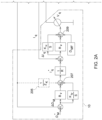
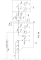
- FIGS. 2A and B illustrate an equivalent circuit and block diagram of the schematic shown in FIG. 1 according to at least one example embodiment.
- the controller 110 obtains a mechanical velocity command ⁇ M ⁇ and reduces the mechanical velocity command ⁇ M ⁇ by a filtered speed ⁇ MF (e.g., filtered by a position sensor) to generate a command difference ⁇ M .
- a filtered speed ⁇ MF e.g., filtered by a position sensor
- the controller 110 multiplies the command difference ⁇ M by a proportional gain of a speed controller 132 (e.g., software based proportion-integral control instructions stored in memory 130 and executed by the processing circuitry 120) B v and multiplies the command difference ⁇ M by an integral gain of the speed controller 132 (within the controller 110) K iv divided by s, where s is the Laplace representation of an excitation frequency j ⁇ .
- the two products ( ⁇ M B v and ⁇ M ( K iv /s)) are summed by the controller 110.
- the controller 110 subtracts the sum by an output of an impedance shaper 202 (which is part of the controller 110) at adder 207.
- the function of the impedance shaper 202 may be performed by the processing circuitry 120 executing instructions stored in the memory 130. The impedance shaper is described in greater detail below.
- the controller 110 generates a current command I q ⁇ by multiplying the output of the adder 207 by 1 / K ⁇ , where K ⁇ is an estimate of a motor constant K.
- K ⁇ is an estimate of a motor constant K.
- the estimate K ⁇ may be provided by a supplier or determined using a torque constant and back EMF (electro-motive force) constant.
- the controller 110 determines a difference ⁇ I q between the current command I q ⁇ and a sensed current I q .
- the controller 110 multiplies the difference ⁇ I q by a proportional gain R v for a current controller 134 (e.g., software based proportion-integral control instructions stored in memory 130 and executed by the processing circuitry 120) and the difference ⁇ I q by a gain of the current controller 134 (within the controller 110) an integral gain K ii for the current controller 134 divided by s.
- a proportional gain R v for a current controller 134 e.g., software based proportion-integral control instructions stored in memory 130 and executed by the processing circuitry 120
- K ii integral gain K ii for the current controller 134 divided by s.
- the two products ( ⁇ I q R v and ⁇ I q ( K ii /s)) are summed by the controller 110 and added to a back EMF decoupling K ⁇ ⁇ MF at adder 209.
- the output of the adder 209 is quadrature voltage V q applied to the electric machine 150.
- the model of the electric machine 150 includes a per phase stator resistance R s , a q-axis current I q , a q-axis motor inductance L q , a back emf of the motor K ⁇ M , a damping B M of the electric machine 150, an inertia J M , a mechanical impedance Z JM and an impedance Z BM of the electric machine 150 for viscous damping.
- the coupler 160 is modeled with the stiffness K c and the damping B c in parallel and the load 175 is modeled with the damping B L and the inertia J L in parallel.
- the stator resistance R s of the electric machine 150 may be 170m ⁇
- the inductance L q of the electric machine 150 may be .8mH
- the inertia J M may be 22.5mg-m 2
- the inertia J L may be 22.5mg-m 2
- the damping B M of the electric machine may be the same as the damping B c of the coupler 160 which may be .11 mNm ⁇ s rad
- the damping B L of the load 175 may be 1 mNm ⁇ s rad
- the stiffness K C of the coupler 160 may be 58 Nm rad
- the virtual resistance R v of the controller 110 may be 7.5 ⁇
- the proportional and integral gains K ii of the current controller 134 may be 14kA.sQ
- the damping of the electric drive 10 may be .5 mNm ⁇ s rad
- the proportional and integral gains K iv of the speed controller 132 may be
- the block diagram of FIGS. 2A-2B includes impedances including the mechanical impedance Z JM and impedance Z BM of the electric machine 150, a mechanical impedance Z JL of the load 175, an impedance of stiffness Z K (s), an impedance of viscous damping Z BC for the coupler and an impedance of viscous damping Z BL for the load.
- impedances including the mechanical impedance Z JM and impedance Z BM of the electric machine 150, a mechanical impedance Z JL of the load 175, an impedance of stiffness Z K (s), an impedance of viscous damping Z BC for the coupler and an impedance of viscous damping Z BL for the load.
- dynamic stability properties of an interconnection of a mechanical power source e.g., torque source or speed source
- a mechanical load e.g., the load 175.
- the overall system is partitioned into two subsystems.
- the partition occurs at dashed line 205.
- an impedance Z EM is determined by looking to the left of the dashed red line and an impedance Z CL is determined by looking to the right of the dashed line.
- the partitioning point can be anywhere along the system, certain points make the analysis insightful in developing the design.
- a preference is to determine if there are issues when interconnecting a first system (e.g., the electric machine 150) with another system (e.g., the load 175).
- FIG. 3 illustrates a mechanical equivalent circuit of the system shown in FIGS. 2A-2B .
- ⁇ M ⁇ G M is a dependent speed source that represents the speed ⁇ M of the electric machine 150 where ⁇ M ⁇ is the command speed and G M represents a closed loop transfer function ⁇ M / ⁇ M ⁇ .
- ⁇ L is a speed of the load 175.
- the electromechanical impedance Z EM includes the electrical and mechanical impedances of the electric machine 150, current regulator impedance, back EMF decoupling and speed controller 132 impedances.
- the impedance Z CL includes the impedance Z C of the coupler 160 and the impedance Z l of the load 175. The partition enables a designer to focus on the impedances separately without the need to derive complete closed loop transfer functions.
- An impedance ratio Z EM / Z cL may be referred to as an interconnection loop gain T I .
- an impedance separation strategy may be used (e.g., partitioning into Z EM and Z CL ), an examination of the frequency response functions Z EM and Z CL is performed to ensure there is at least 15dB separation, which results in a unity closed loop interconnection gain G I .
- separation between the drive impedance Z EM and the load impedance Z CL is performed by the impedance shaper 202. More specifically, kernel impedance may be used to enforce separation between the impedances Z EM (s) and Z CL (s) .
- FIG. 4 illustrates a block diagram illustrating paralleling of feedback gain.
- X(s) is an input and Y(s) is an output with a forward path gain G 1 (s) and a negative feedback gain G 2 (s).
- the electromechanical impedance is ⁇ M s T M s
- the reciprocal of the kernel impedance Y K (s) accounts for the input being the motor speed ⁇ M (s) and output is torque, which appears similar to admittance.
- FIG. 5 illustrates frequency response functions over a targeted bandwidth (e.g., on a logarithmic scale such as approximately zero to approximately 100,000 Hz) of a drive impedance Z EM ( s ) without kernel shaping, a drive impedance Z EM_ shaped(s) with kernel shaping and a load impedance Z CL (s) according to an example embodiment.
- the magnitude of the drive impedance Z EM (s) without impedance shaping intersects with the magnitude of the load impedance Z CL (s) at around 100Hz and 300Hz and then the magnitude of the load impedance Z CL (s) becomes smaller than the magnitude of the drive impedance Z EM (s) and anti-resonance at around 250 Hz.
- the controller is configured to provide impedance shaping according to some example embodiments in accordance with an impedance control parameter (e.g., kernel impedance control parameter), such as a targeted kernel impedance (response or curve) Z K (s) to shape Z EM (s) (i.e., Z EM _shaped(s)) such that Z CL (s)>Z EM _shaped ( s ) for the magnitude of the complete frequency response function without the need to modify the magnitude of the load impedance Z CL (s) versus frequency, which may be fixed or subject to constrained operating conditions associated with the mechanical load.
- an impedance control parameter e.g., kernel impedance control parameter
- the magnitude of the frequency response function of a drive impedance with impedance shaping Z EM _shaped(s) does not intersect the magnitude of the frequency response function of the load impedance Z CL (s) due to the kernel impedance Z K (s) .
- K HF is a high frequency impedance value and is static once implemented on the controller.
- the impedance K HF may be set based on the system and empirical data.
- a first zero frequency ⁇ z1 are set at an anti-resonance frequency of 250Hz and subsequent zeros ⁇ z2 and ⁇ z3 are at half and a third of the first zero frequency ⁇ z1 , respectively.
- a first pole frequency ⁇ p1 is determined to be lower than a bandwidth of the speed controller 132 (e.g., 35Hz) such as 20Hz and subsequent poles ⁇ p2 and ⁇ p3 are set at half and a third of the first pole frequency ⁇ p1 , respectively.
- a transfer function like Z K (s) shown above has a numerator and denominator.
- the numerator has the zeros of the transfer function, meaning at those frequencies the output is zero.
- the denominator has the poles of the transfer function and they become zero at specific frequencies.
- pole/zero frequencies permits for a relatively smoother change in impedance. Moreover, the separation of the pole frequencies determines the DC gain of the kernel impedance. Spacing of the pole frequencies may be adjusted to preserve an original drive impedance from DC to mid-band frequencies.
- an impedance analysis decomposes an overall system into products of open and closed loop gains.
- a graphical impedance based analysis as shown in FIG. 5 shows that as long as a clear separation between Z EM and Z CL exists, the closed loop interconnection gain is unity, thus removing the need for deriving higher order transfer functions that may be used for further analysis and evaluation.
- the partitioning of the overall system enables analysis of a sixth order system into two systems where the drive is a fourth order system and the load a second order system. This approach enables system designers to have more flexibility during the design process as the interconnection properties for the drive and the load maybe co-designed.
- Impedance based analysis enables visualization of non-unity negative feedback loops as impedances in parallel with forward path impedance.
- loads connected to the electric machine can also be represented as parallel impedances.
- the parallel impedance approach augments a graphical impedance based approach thus removing the need of tedious block diagram analysis.
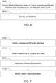
- FIG. 6 illustrates a method of driving a load machine according to one or more example embodiments.
- the method of FIG. 6 may be performed by the electric drive shown in FIG. 1 .
- a controller e.g., the controller 110 controls an electric machine based on an identified drive impedance of the electric machine and an identified impedance of the load machine and a coupler.
- the controlling controls the electric machine further based on a feedback impedance, e.g., the feedback impedance Z K (s) .
- the controlling includes determining the identified drive impedance of the electric machine (e.g., drive impedance Z EM ( s )) based on a first impedance of the electric machine (e.g., the impedance Z JM ) and the feedback impedance (e.g., Z K (s) ) .
- the identified drive impedance of the electric machine e.g., drive impedance Z EM ( s )
- a first impedance of the electric machine e.g., the impedance Z JM
- the feedback impedance e.g., Z K (s)
- the controlling includes determining frequencies (e.g., zero frequencies ⁇ z1 , ⁇ z2 and ⁇ z3 and pole frequencies ⁇ p1 , ⁇ p2 and ⁇ p3 ) at which a frequency response function (FRF) of the drive impedance of the electric machine and a FRF of the identified impedance of the load machine and a coupler cross, and determining the identified drive impedance based on the determined frequencies.
- the controller determines the drive impedance such that a magnitude across the FRF of the determined impedance does not cross a magnitude of the FRF of the identified impedance of the load machine and the coupler.
- the controller drives the load machine based on the control of the electric machine. More specifically, the controller controls the electric machine to drive the load machine through a coupler.
- FIG. 7 illustrates a method of modeling an electric machine system according to one or more example embodiments.
- the electric machine system may be the system shown in FIGS. 1-2 .
- an impedance of an electric machine (e.g., Z EM ) is obtained by a controller.
- an impedance of a coupler and a load machine (e.g., Z CL ) is obtained by the controller.
- a feedback impedance (e.g., Z K ) is determined.
- the feedback impedance may be determined by the controller.
- the controller models the electric machine system based on the impedance of the electric machine, the impedance of the coupler and the load and the feedback impedance.
- the feedback impedance is determined such that a magnitude of the FRF of the impedance of the electric machine does not cross a magnitude of the FRF of the impedance of the load machine and the coupler.
- the controlling includes determining frequencies (e.g., zero frequencies ⁇ z1 , ⁇ z2 and ⁇ z3 and pole frequencies ⁇ p1 , ⁇ p2 and ⁇ p3 ) at which a frequency response function (FRF) of the drive impedance of the electric machine and a FRF of the impedance of the load machine and the coupler cross, and determining the drive impedance based on the determined frequencies.
- the controller determines the drive impedance such that a FRF of the determined impedance does not cross the FRF of the impedance of the load machine and the coupler.
- the controller drives the load machine based on the control of the electric machine. More specifically, the controller controls the electric machine to drive the load machine through a coupler.
- Some example embodiments may be described with reference to acts and symbolic representations of operations (e.g., in the form of flow charts, flow diagrams, data flow diagrams, structure diagrams, block diagrams, etc.) that may be implemented in conjunction with units and/or devices discussed in more detail below.
- a function or operation specified in a specific block may be performed differently from the flow specified in a flowchart, flow diagram, etc.
- functions or operations illustrated as being performed serially in two consecutive blocks may actually be performed concurrently, simultaneously, or in some cases be performed in reverse order.
Landscapes
- Engineering & Computer Science (AREA)
- Power Engineering (AREA)
- Control Of Electric Motors In General (AREA)
Abstract
Description
- The present application hereby claims priority under 35 U.S.C. § 119 to
U.S. Provisional Application No. 63/265,136 filed December 8, 2021 U.S. Provisional Application No. 63/333,779, filed April 22, 2022 - Development of electric drives often includes an analysis of dynamic phenomena of interactions between various components that form a powertrain, which may include several inertia elements and compliance elements with some damping. Selection of powertrain components are done to reduce and/or minimize undamped oscillatory responses during various load transients on the powertrain.
- Mechanical systems can be modeled by using electrical analogs to analyze dynamic properties and to design systems. The wide availability of computer based simulation and hardware-in-loop engineering tools such as MATLAB™, SIMULINK™ and Simscape™ computer software, which are trademarks of The MathWorks, Inc., of Natick Massachusetts, have broadened the use of model-based control approaches. These engineering tools enable modeling and designing systems across multiple physical domains such as electro-mechanical systems.
- In accordance with one aspect of the disclosure, a drive system comprises a load machine and a coupler. An electric machine is coupled to the load machine via the coupler and configured to drive the load machine. A controller is configured to control the electric machine based on a target shaping of impedance control parameters (e.g., by a kernel impedance control parameter) of the drive impedance versus frequency response (e.g., a target shaping of magnitude, phase or both of the drive impedance versus frequency response) of the electric machine and/or based on an impedance (e.g., fixed or constrained impedance versus frequency response) of the load machine and the coupler.
- In accordance with another aspect of the disclosure, the controller is configured to select and tune control parameters that are derived from modeling an interconnection of an electro-mechanical system, such as a motor drive to a complex mechanical load or an electric machine (e.g., generator), as a complex electrical network. Because the electro-mechanical system can include intentional and unintended feedback paths that can lead to instabilities, motor drive systems with torsional loads impose constraints and challenges on control parameters of the electric machine, such as the dynamic performance of speed control.
- In accordance with a yet another aspect of the disclosure, various control strategies have been developed to overcome the technical issues, such as feedback paths, that are illustrated using a two-inertia model of the electro-mechanical system, representing the simplest model of a compliant interconnected electromechanical system.
- Some example embodiments provide systems and methods for using impedance separation and impedance shaping.
- The various features and advantages of the non-limiting embodiments herein may become more apparent upon review of the detailed description in conjunction with the accompanying drawings. The accompanying drawings are merely provided for illustrative purposes and should not be interpreted to limit the scope of the claims. The accompanying drawings are not to be considered as drawn to scale unless explicitly noted. For the purposes of clarity, various dimensions of the drawings may have been exaggerated.
-
FIG. 1 illustrates a schematic of an electric drive connected to a mechanical load according to an example embodiment; -
FIG. 2 illustrates sections ofFIGS. 2A and2B ; -
FIGS. 2A-B illustrate an equivalent circuit and block diagram of the schematic shown inFIG. 1 ; -
FIG. 3 illustrates a mechanical equivalent circuit of the system shown inFIGS. 2A-2B ; -
FIG. 4 illustrates a block diagram illustrating paralleling of feedback gain according to an example embodiment; -
FIG. 5 illustrates frequency response functions of a drive impedance without kernel shaping, a drive impedance with kernel shaping and a load impedance according to an example embodiment; -
FIG. 6 illustrates a method of driving a load machine according to an example embodiment; and -
FIG. 7 illustrates a method of modeling an electric machine system according to an example embodiment. - As shown in
FIG. 1 , anelectric drive 10 includes aninverter 105 and acontroller 110 to generate commands (e.g., voltage and/or current commands) for an electric machine 150 (e.g., a motor). Theelectric machine 150 is part of a modeled electro-mechanical system 152. In addition to theelectric machine 150, the modeled electro-mechanical system 152 includes amechanical load 175 and acoupler 160. Theelectric machine 150 is coupled to themechanical load 175 though the coupler 160 (e.g., a compliant coupler modelled by stiffness and damping properties). Thecoupler 160 comprises a mechanical, rotational coupler, such as a flexible coupler, a bellows coupler, a flexible joint, a universal joint, a flange coupler, a gearbox, or a transmission, for example. Theelectric machine 150 is configured to drive themechanical load 175 based on the commands provided to theelectric machine 150 from thecontroller 110. - In some example embodiments, the
controller 110 includesprocessing circuitry 120 andmemory 130. Thecontroller 110 is configured to perform the methods and algorithms described herein. In some example embodiments, theprocessing circuitry 120 is configured to execute instructions stored in thememory 130 to cause theelectric drive 10 to perform the methods and algorithms described herein. - The term 'processing circuitry,' as used in the present disclosure, may refer to, for example, hardware including logic circuits; a hardware/software combination such as a processor executing software; or a combination thereof. For example, the hardware more specifically may include, but is not limited to, a central processing unit (CPU), an arithmetic logic unit (ALU), a digital signal processor, a microcomputer, a field programmable gate array (FPGA), a System-on-Chip (SoC), a programmable logic unit, a microprocessor, application-specific integrated circuit (ASIC), etc.
- According to some example embodiments, the
memory 130 may be a tangible, non-transitory computer-readable medium, such as a Random Access Memory (RAM), a flash memory, a Read Only Memory (ROM), an Electrically Programmable ROM (EPROM), an Electrically Erasable Programmable ROM (EEPROM), registers, a hard disk, a removable disk, a Compact Disk (CD) ROM, any combination thereof, or any other form of storage medium known in the art. - In at least some example embodiments, the controller is configured to control the electric machine further based on a feedback impedance.
- In at least some example embodiments, the controller is configured to determine the drive impedance of the electric machine based on a first impedance of the electric machine and the feedback impedance.
- In at least some example embodiments, the controller is configured to determine crossing frequencies (of an impedance magnitude versus frequency and of an impedance phase versus frequency) at which a frequency response function (FRF) of the drive impedance of the electric machine and a FRF of the impedance of the mechanical load (e.g., load machine) and a coupler cross each other, and determine the drive impedance based on the determined frequencies. A FRF for a modeled electro-mechanical system that comprises an electric machine 150 (e.g., an electric motor or drive electric machine operational in motoring mode), a mechanical (rotational)
coupler 160 and a mechanical load 175 (e.g., drivetrain of a ground vehicle with wheels or tracks that engage the ground, or a generator load or electric machine load operational in a generating mode) may be defined as one or more of the following: (a) a magnitude of impedance versus frequency response (ZEM(s)) of an electric machine, (b) a magnitude of impedance versus frequency response of the mechanical load (ZCL(s)), (c) a (magnitude) control parameter or kernel magnitude versus frequency response (Zk(s)) for an electronic controller, and (d) a target or shaped magnitude of impedance versus frequency response of the electric machine (ZEM(s)), (e) a phase of impedance versus frequency response (ZEM(s)) of an electric machine, (f) a phase of impedance versus frequency response of a mechanical load (ZCL(s)), (g) a (phase) control parameter or kernel magnitude versus frequency response (Zk(s)) for an electronic controller, and (d) a target or shaped phase of impedance versus frequency response of the electric machine (ZEM_shaped(s)), which are described in greater detail inFIG. 5 . - In at least some example embodiments, the controller is configured to determine the drive impedance such that a FRF of the determined impedance does not cross the FRF of the impedance of the load machine and a coupler.
- Referring to
FIG. 1 , mechanical resonance may be caused by the combination of compliant couplings and high gains on a drive to meet the high-performance demands. The compliance comes from the mechanical interconnections like shafts, couplers and gearboxes. If the inertia of thecoupler 160 is small compared to theelectric machine 150 and theload 175, the stiffness can be lumped into a single spring that connects the motor and load as shown inFIG. 1 . The time domain dynamic motion for the system ofFIG. 1 may be:

electric machine 150, Tl , Jl, ωl and θl are electro-mechanical torque, inertia, mechanical speed and phase values, respectively, of theload 175, and Kc and Bc are a stiffness and a damping, respectively, of thecoupler 160. - A transfer function from the electro-mechanical torque TE to a load velocity, ΩL can then be derived from
Equations 
- However, the transfer function in Equation (3) does not provide insight into some system design parameters. Furthermore, there is no insight in terms of energy exchange between the electrical and mechanical domains.
- Accordingly, at least some example embodiments use impedance-separation and impedance-shaping for electro-mechanical systems to improve dynamics during transients arising from interactions among interconnected systems. Impedance-shaping provides designs with adequate impedance margins to mitigate any potential resonances.
-
FIGS. 2A andB illustrate an equivalent circuit and block diagram of the schematic shown inFIG. 1 according to at least one example embodiment. - As shown in
FIGS. 2A andB , thecontroller 110 obtains a mechanical velocity command

- The
controller 110 multiplies the command difference ΔΩM by a proportional gain of a speed controller 132 (e.g., software based proportion-integral control instructions stored inmemory 130 and executed by the processing circuitry 120) Bv and multiplies the command difference ΔΩM by an integral gain of the speed controller 132 (within the controller 110) Kiv divided by s, where s is the Laplace representation of an excitation frequency jω. The two products (ΔΩMBv and ΔΩM (Kiv /s)) are summed by thecontroller 110. Thecontroller 110 subtracts the sum by an output of an impedance shaper 202 (which is part of the controller 110) atadder 207. The function of the impedance shaper 202 may be performed by theprocessing circuitry 120 executing instructions stored in thememory 130. The impedance shaper is described in greater detail below. - The
controller 110 generates a current command
adder 207 by 1 / K̂, where K̂ is an estimate of a motor constant K. The estimate K̂ may be provided by a supplier or determined using a torque constant and back EMF (electro-motive force) constant. Thecontroller 110 determines a difference ΔIq between the current command
- The
controller 110 multiplies the difference ΔIq by a proportional gain Rv for a current controller 134 (e.g., software based proportion-integral control instructions stored inmemory 130 and executed by the processing circuitry 120) and the difference ΔIq by a gain of the current controller 134 (within the controller 110) an integral gain Kii for thecurrent controller 134 divided by s. - The two products (ΔIqRv and ΔIq (Kii /s)) are summed by the
controller 110 and added to a back EMF decoupling K̂ ΩMF atadder 209. The output of theadder 209 is quadrature voltage Vq applied to theelectric machine 150. - The model of the
electric machine 150 includes a per phase stator resistance Rs , a q-axis current Iq, a q-axis motor inductance Lq, a back emf of the motor KΩM, a damping BM of theelectric machine 150, an inertia JM, a mechanical impedance ZJM and an impedance ZBM of theelectric machine 150 for viscous damping. - The
coupler 160 is modeled with the stiffness Kc and the damping Bc in parallel and theload 175 is modeled with the damping BL and the inertia JL in parallel. - In some example embodiments, the stator resistance Rs of the
electric machine 150 may be 170mΩ, the inductance Lq of theelectric machine 150 may be .8mH, the inertia JM may be 22.5mg-m2, the inertia JL may be 22.5mg-m2, the damping BM of the electric machine may be the same as the damping Bc of thecoupler 160 which may be
load 175 may be
coupler 160 may be
controller 110 may be 7.5Ω, the proportional and integral gains Kii of thecurrent controller 134 may be 14kA.sQ, the damping of theelectric drive 10 may be
speed controller 132 may be
- In addition, the block diagram of
FIGS. 2A-2B includes impedances including the mechanical impedance ZJM and impedance ZBM of theelectric machine 150, a mechanical impedance ZJL of theload 175, an impedance of stiffness ZK (s), an impedance of viscous damping ZBC for the coupler and an impedance of viscous damping ZBL for the load. - Representation of the constitutive properties of the lumped parameters using operational impedances represented by complex quantities with a magnitude and phase allows the determination of the frequency response of the circuits to steady state sinusoidal excitation voltages and/or currents. Mechanical equivalent circuits can be similarly used for a graphical representation of rotational mechanical systems with interconnections of components with an equivalent complex variable abstraction of their velocity Ω - torque T relationships.
- Mechanical impedance may be reflected as a ratio of Zm = Ω(s)/T(s) where s is the Laplace representation of the excitation frequency jω.
- The rotational inertia of J kgm2 has a mechanical impedance of ZJ = 1 / Js, the rotation spring of


- Using impedances, dynamic stability properties of an interconnection of a mechanical power source (e.g., torque source or speed source) to a mechanical load can be examined by modeling an internal impedance of the power source (e.g., the electric machine 150) and comparing it with the mechanical impedance of a load (e.g., the load 175).
- In at least some example embodiments, the overall system is partitioned into two subsystems. In the system shown in
FIGS. 2A-2B , the partition occurs at dashedline 205. Following the partitioning, an impedance ZEM is determined by looking to the left of the dashed red line and an impedance ZCL is determined by looking to the right of the dashed line. It should be understood that the partitioning point can be anywhere along the system, certain points make the analysis insightful in developing the design. In some example embodiments, a preference is to determine if there are issues when interconnecting a first system (e.g., the electric machine 150) with another system (e.g., the load 175). -
FIG. 3 illustrates a mechanical equivalent circuit of the system shown inFIGS. 2A-2B . - As shown in
FIG. 3 ,
electric machine 150 where

- ΩL is a speed of the
load 175. The electromechanical impedance ZEM includes the electrical and mechanical impedances of theelectric machine 150, current regulator impedance, back EMF decoupling andspeed controller 132 impedances. The impedance ZCL includes the impedance ZC of thecoupler 160 and the impedance Zl of theload 175. The partition enables a designer to focus on the impedances separately without the need to derive complete closed loop transfer functions. - A load speed to speed command transfer function can be written as


- An impedance ratio ZEM /ZcL may be referred to as an interconnection loop gain TI . A load loop gain is TCL = ZEM /ZCL and the drive loop gain is TM. Consequently, an overall closed loop transfer function is a product of three loop gains and may be written in closed loop gain form as:

- In particular, if ZR , > ZL, Zl > Zc and TM >> 1 then the closed loop interconnection gain GI , closed loop load-coupler gain GLC and closed loop motor gain GM will be unity, and the stability of the interconnected system occurs.
- In some example embodiments an impedance separation strategy may be used (e.g., partitioning into ZEM and ZCL), an examination of the frequency response functions ZEM and ZCL is performed to ensure there is at least 15dB separation, which results in a unity closed loop interconnection gain GI . In some examples, the load inertia is reduced to JL = 2.25mg - m 2 to enforce separation and keeping all other parameters unchanged.
- In other example embodiments, separation between the drive impedance ZEM and the load impedance ZCL is performed by the impedance shaper 202. More specifically, kernel impedance may be used to enforce separation between the impedances ZEM (s) and ZCL (s).
-
FIG. 4 illustrates a block diagram illustrating paralleling of feedback gain. In the system shown inFIG. 4 , X(s) is an input and Y(s) is an output with a forward path gain G1(s) and a negative feedback gain G2(s). The transfer function is


- Extending the concept to the systems in
FIGS. 2 and3 , the electromechanical impedance is
- Thus, X(s) becomes TM(s) and Y(s) becomes ΩM(s) with the drive impedance ZEM(s) being the gain G1(s) before impedance shaping and G2(s) becomes a reciprocal of the kernel impedance, which is 1/ZK(s) = YK(s). The reciprocal of the kernel impedance YK(s) accounts for the input being the motor speed ΩM(s) and output is torque, which appears similar to admittance. Thus,

- For a gain in the feedback between ΩM(s) and torque command input TM(s), the reciprocal of that gain appears in parallel with the original output impedance of the drive. If the kernel impedance ZK(s) is larger than the drive impedance ZEM(s) then the drive impedance ZEM(s) dominates the overall impedance and vice-versa. Hence, the designer has the freedom to choose the dominating impedance in the frequencies of interest.
-
FIG. 5 illustrates frequency response functions over a targeted bandwidth (e.g., on a logarithmic scale such as approximately zero to approximately 100,000 Hz) of a drive impedance ZEM (s) without kernel shaping, a drive impedance ZEM_shaped(s) with kernel shaping and a load impedance ZCL(s) according to an example embodiment. The magnitude of the drive impedance ZEM (s) without impedance shaping intersects with the magnitude of the load impedance ZCL(s) at around 100Hz and 300Hz and then the magnitude of the load impedance ZCL(s) becomes smaller than the magnitude of the drive impedance ZEM(s) and anti-resonance at around 250 Hz. However, as shown, the controller is configured to provide impedance shaping according to some example embodiments in accordance with an impedance control parameter (e.g., kernel impedance control parameter), such as a targeted kernel impedance (response or curve) ZK(s) to shape ZEM(s) (i.e., ZEM_shaped(s)) such that ZCL(s)>ZEM_shaped(s) for the magnitude of the complete frequency response function without the need to modify the magnitude of the load impedance ZCL(s) versus frequency, which may be fixed or subject to constrained operating conditions associated with the mechanical load. As shown, the magnitude of the frequency response function of a drive impedance with impedance shaping ZEM_shaped(s) does not intersect the magnitude of the frequency response function of the load impedance ZCL(s) due to the kernel impedance ZK(s). - In some example embodiments such as in
FIGS. 2-3 and5 , the kernel impedance ZK(s) is
- Setting the impedance KHF as a high frequency gain enforces separation in and around an anti-resonance frequency. The impedance KHF may be set based on the system and empirical data.
- A first zero frequency ωz1 are set at an anti-resonance frequency of 250Hz and subsequent zeros ωz2 and ωz3 are at half and a third of the first zero frequency ωz1 , respectively. Similarly, a first pole frequency ωp1 is determined to be lower than a bandwidth of the speed controller 132 (e.g., 35Hz) such as 20Hz and subsequent poles ωp2 and ωp3 are set at half and a third of the first pole frequency ωp1 , respectively.
- In general, a transfer function like ZK(s) shown above has a numerator and denominator. The numerator has the zeros of the transfer function, meaning at those frequencies the output is zero. Similarly, the denominator has the poles of the transfer function and they become zero at specific frequencies.
- The separation of pole/zero frequencies permits for a relatively smoother change in impedance. Moreover, the separation of the pole frequencies determines the DC gain of the kernel impedance. Spacing of the pole frequencies may be adjusted to preserve an original drive impedance from DC to mid-band frequencies.
- As describe above, an impedance analysis decomposes an overall system into products of open and closed loop gains. A graphical impedance based analysis as shown in
FIG. 5 shows that as long as a clear separation between ZEM and ZCL exists, the closed loop interconnection gain is unity, thus removing the need for deriving higher order transfer functions that may be used for further analysis and evaluation. The partitioning of the overall system enables analysis of a sixth order system into two systems where the drive is a fourth order system and the load a second order system. This approach enables system designers to have more flexibility during the design process as the interconnection properties for the drive and the load maybe co-designed. Instances where the load properties are unknown, drive designers can still provide specifications in terms of the desired properties for the load impedance to maintain separation between ZEM and ZCL. Impedance based analysis enables visualization of non-unity negative feedback loops as impedances in parallel with forward path impedance. Moreover, loads connected to the electric machine can also be represented as parallel impedances. The parallel impedance approach augments a graphical impedance based approach thus removing the need of tedious block diagram analysis. -
FIG. 6 illustrates a method of driving a load machine according to one or more example embodiments. The method ofFIG. 6 may be performed by the electric drive shown inFIG. 1 . - At S605, a controller (e.g., the controller 110) controls an electric machine based on an identified drive impedance of the electric machine and an identified impedance of the load machine and a coupler.
- In an example embodiment and as described above, the controlling controls the electric machine further based on a feedback impedance, e.g., the feedback impedance ZK(s).
- In an example embodiment, the controlling includes determining the identified drive impedance of the electric machine (e.g., drive impedance ZEM (s)) based on a first impedance of the electric machine (e.g., the impedance ZJM ) and the feedback impedance (e.g., ZK(s)).
- In an example embodiment, the controlling includes determining frequencies (e.g., zero frequencies ωz1 , ω z2 and ωz3 and pole frequencies ωp1 , ωp2 and ωp3 ) at which a frequency response function (FRF) of the drive impedance of the electric machine and a FRF of the identified impedance of the load machine and a coupler cross, and determining the identified drive impedance based on the determined frequencies. The controller determines the drive impedance such that a magnitude across the FRF of the determined impedance does not cross a magnitude of the FRF of the identified impedance of the load machine and the coupler.
- At S610, the controller drives the load machine based on the control of the electric machine. More specifically, the controller controls the electric machine to drive the load machine through a coupler.
-
FIG. 7 illustrates a method of modeling an electric machine system according to one or more example embodiments. The electric machine system may be the system shown inFIGS. 1-2 . - At S705, an impedance of an electric machine (e.g., ZEM ) is obtained by a controller.
- At S710, an impedance of a coupler and a load machine (e.g., ZCL ) is obtained by the controller.
- At S715, a feedback impedance (e.g., ZK ) is determined. For example, the feedback impedance may be determined by the controller.
- As S720, the controller models the electric machine system based on the impedance of the electric machine, the impedance of the coupler and the load and the feedback impedance. For example, the feedback impedance is determined such that a magnitude of the FRF of the impedance of the electric machine does not cross a magnitude of the FRF of the impedance of the load machine and the coupler.
- In an example embodiment, the controlling includes determining frequencies (e.g., zero frequencies ωz1 , ωz2 and ωz3 and pole frequencies ωp1 , ωp2 and ωp3 ) at which a frequency response function (FRF) of the drive impedance of the electric machine and a FRF of the impedance of the load machine and the coupler cross, and determining the drive impedance based on the determined frequencies. The controller determines the drive impedance such that a FRF of the determined impedance does not cross the FRF of the impedance of the load machine and the coupler.
- At S610, the controller drives the load machine based on the control of the electric machine. More specifically, the controller controls the electric machine to drive the load machine through a coupler.
- Some example embodiments may be described with reference to acts and symbolic representations of operations (e.g., in the form of flow charts, flow diagrams, data flow diagrams, structure diagrams, block diagrams, etc.) that may be implemented in conjunction with units and/or devices discussed in more detail below. Although discussed in a particular manner, a function or operation specified in a specific block may be performed differently from the flow specified in a flowchart, flow diagram, etc. For example, functions or operations illustrated as being performed serially in two consecutive blocks may actually be performed concurrently, simultaneously, or in some cases be performed in reverse order.
- It will be understood that when an element is referred to as being "connected" or "coupled" to another element, it may be directly connected or coupled to the other element or intervening elements may be present. As used herein the term "and/or" includes any and all combinations of one or more of the associated listed items.
Claims (15)
- A system comprising:a load machine (175);a coupler (160);an electric machine (150) coupled to the load machine (175) via the coupler (160) and configured to drive the load machine (175); anda controller (110) configured to control the electric machine (150) based on a drive impedance of the electric machine (150) and an impedance of the load machine (175) and the coupler (160).
- The system of claim 1, wherein the controller (110) is configured to control the electric machine (150) further based on a feedback impedance.
- The system of claim 2, wherein the controller (110) is configured to determine the drive impedance of the electric machine (150) based on a first impedance of the electric machine (150) and the feedback impedance.
- The system of claim 3, wherein the controller (110) is configured to,determine crossing frequencies at which a magnitude of a frequency response function (FRF) of the drive impedance of the electric machine (150) and a magnitude of a FRF of the impedance of the load machine (175) and the coupler (160) cross each other, anddetermine the drive impedance based on the determined crossing frequencies.
- The system of claim 4, wherein the controller (110) is configured to determine the drive impedance such that a magnitude of the FRF of the determined drive impedance does not cross the magnitude of the FRF of the impedance of the load machine (175) and the coupler (160).
- The system of claim 2, wherein the feedback impedance is:

- A method comprising:controlling (S605) an electric machine based on an identified drive impedance of the electric machine and an identified impedance of a load machine and a coupler; anddriving (S610) the load machine based on the control.
- The method of claim 7, wherein the controlling (S605) controls the electric machine further based on a feedback impedance.
- The method of claim 8, wherein the controlling (S605) includes,
determining the identified drive impedance of the electric machine based on a first impedance of the electric machine and the feedback impedance. - The method of claim 9, wherein the controlling (S605) includes,determining crossing frequencies at which a magnitude of a frequency response function (FRF) of the drive impedance of the electric machine and a magnitude of a FRF of the impedance of the load machine and the coupler cross each other, anddetermining the identified drive impedance based on the determined crossing frequencies.
- The method of claim 10, wherein the determining the identified drive impedance determines the identified drive impedance such that a FRF of the identified drive impedance does not cross the FRF of the identified impedance of the load machine and the coupler.
- The method of claim 8, wherein the feedback impedance is:

- A method of modeling an electric machine system, the method comprising:obtaining (S705) an impedance of an electric machine;obtaining (S710) an impedance of a coupler and a load machine;determining (S715) a feedback impedance; andmodeling (S720) the electric machine system based on the impedance of the electric machine, the impedance of the coupler and the load machine and the feedback impedance.
- The method of claim 13, wherein the modeling (S720) includes,
shaping the impedance of the electric machine to be lower than the impedance of the coupler and the load machine based on the feedback impedance. - The method of claim 14, wherein the determining (S715) the feedback impedance determines the feedback impedance as:

Applications Claiming Priority (3)
| Application Number | Priority Date | Filing Date | Title |
|---|---|---|---|
| US202163265136P | 2021-12-08 | 2021-12-08 | |
| US202263333779P | 2022-04-22 | 2022-04-22 | |
| US17/939,593 US12113462B2 (en) | 2021-12-08 | 2022-09-07 | Electric drive systems using impedance separation and impedance shaping |
Publications (1)
| Publication Number | Publication Date |
|---|---|
| EP4195501A1 true EP4195501A1 (en) | 2023-06-14 |
Family
ID=83438633
Family Applications (1)
| Application Number | Title | Priority Date | Filing Date |
|---|---|---|---|
| EP22197475.1A Pending EP4195501A1 (en) | 2021-12-08 | 2022-09-23 | Electric drive systems using impedance separation and impedance shaping |
Country Status (2)
| Country | Link |
|---|---|
| US (1) | US12113462B2 (en) |
| EP (1) | EP4195501A1 (en) |
Citations (1)
| Publication number | Priority date | Publication date | Assignee | Title |
|---|---|---|---|---|
| EP2621752B1 (en) * | 2010-09-29 | 2019-07-10 | Nissan Motor Co., Ltd | Motor controlling apparatus |
Family Cites Families (3)
| Publication number | Priority date | Publication date | Assignee | Title |
|---|---|---|---|---|
| US5892198A (en) * | 1996-03-29 | 1999-04-06 | Lam Research Corporation | Method of and apparatus for electronically controlling r.f. energy supplied to a vacuum plasma processor and memory for same |
| NO20100691A1 (en) * | 2010-05-12 | 2011-11-14 | Roxar Flow Measurement As | Transmission system for communication between borehole elements |
| CN101873110B (en) * | 2010-05-28 | 2013-07-10 | 常州瑞思杰尔电子科技有限公司 | Radio frequency matcher |
-
2022
- 2022-09-07 US US17/939,593 patent/US12113462B2/en active Active
- 2022-09-23 EP EP22197475.1A patent/EP4195501A1/en active Pending
Patent Citations (1)
| Publication number | Priority date | Publication date | Assignee | Title |
|---|---|---|---|---|
| EP2621752B1 (en) * | 2010-09-29 | 2019-07-10 | Nissan Motor Co., Ltd | Motor controlling apparatus |
Non-Patent Citations (2)
| Title |
|---|
| AGUIRRE-OLLINGER GABRIEL ET AL: "An admittance shaping controller for exoskeleton assistance of the lower extremities", AUTONOMOUS ROBOTS, KLUWER ACADEMIC PUBLISHERS, DORDRECHT, NL, vol. 40, no. 4, 19 August 2015 (2015-08-19), pages 701 - 728, XP035900690, ISSN: 0929-5593, [retrieved on 20150819], DOI: 10.1007/S10514-015-9490-8 * |
| THYAGARAJAN LAV ET AL: "Design of Electric Drive Dynamics using Impedance Separation and Impedance Shaping", 2022 IEEE TRANSPORTATION ELECTRIFICATION CONFERENCE & EXPO (ITEC), IEEE, 15 June 2022 (2022-06-15), pages 172 - 179, XP034145405, [retrieved on 20220707], DOI: 10.1109/ITEC53557.2022.9813994 * |
Also Published As
| Publication number | Publication date |
|---|---|
| US12113462B2 (en) | 2024-10-08 |
| US20230179133A1 (en) | 2023-06-08 |
Similar Documents
| Publication | Publication Date | Title |
|---|---|---|
| CN104798073B (en) | Power train modeling device | |
| US12291107B2 (en) | Method for controlling a powertrain of an electric vehicle, data processing device, computer program, computer-readable medium, and powertrain | |
| Sundström et al. | Selecting and utilizing sequential residual generators in FDI applied to hybrid vehicles | |
| Fouad et al. | Subsychronous Resonance Zones in the IEEE" Bench Mark" Power System | |
| Wang et al. | Self-adaptive differential evolution algorithm with hybrid mutation operator for parameters identification of PMSM | |
| CN103246934A (en) | Classification optimization method used for equivalent model parameters of electrical power system and based on trace sensitivity | |
| Makris | On the physical meaning of time-domain constitutive models with complex parameters | |
| dos Santos et al. | Multiphysics thermal and NVH modeling: integrated simulation of a switched reluctance motor drivetrain for an electric vehicle | |
| CN115935499A (en) | Hybrid coupling box load spectrum construction method and related equipment | |
| US12113462B2 (en) | Electric drive systems using impedance separation and impedance shaping | |
| Renkert et al. | Component-based design optimization of multirotor aircraft | |
| Ramakrishnan et al. | Multidisciplinary design of electric vehicles based on hierarchical multi-objective optimization | |
| Hirata et al. | Final state control-based active compensation for backlash in vibration suppression of automobile powertrain | |
| EP3428606B1 (en) | Simulation program | |
| Nemeș et al. | Real-time simulation of scaled propulsion unit for light electric vehicles | |
| Chen et al. | Bond graph modeling of electric vehicle drive system considering electromechanical coupling effect | |
| Margielewicz et al. | Study of flexible couplings non-linear dynamics using bond graphs | |
| Hatlehol et al. | A Modeling Framework for Stability and Dynamic Analysis of Marine Hybrid Electric Powertrains | |
| JP4663689B2 (en) | Simulation apparatus and method | |
| Ju et al. | Cutting force and vibration prediction of milling processes regarding the nonlinear behavior of cascade controlled feed drives | |
| JP4512769B1 (en) | Critical failure removal time calculation method, program | |
| Ciceo et al. | Model-based design and testing for the energy consumption analysis of the electric vehicles | |
| Faradja et al. | Local bifurcation of brushless DC motor through a mechanical parameter: The viscous damping coefficient | |
| Caillard et al. | Mono and bi-Level optimization architectures for powertrain design | |
| Inkov et al. | Energy Characteristics of an Electric Drive with Direct Torque Control for a Permanent-Magnet Synchronous Motor |
Legal Events
| Date | Code | Title | Description |
|---|---|---|---|
| PUAI | Public reference made under article 153(3) epc to a published international application that has entered the european phase |
Free format text: ORIGINAL CODE: 0009012 |
|
| STAA | Information on the status of an ep patent application or granted ep patent |
Free format text: STATUS: THE APPLICATION HAS BEEN PUBLISHED |
|
| AK | Designated contracting states |
Kind code of ref document: A1 Designated state(s): AL AT BE BG CH CY CZ DE DK EE ES FI FR GB GR HR HU IE IS IT LI LT LU LV MC MK MT NL NO PL PT RO RS SE SI SK SM TR |
|
| STAA | Information on the status of an ep patent application or granted ep patent |
Free format text: STATUS: REQUEST FOR EXAMINATION WAS MADE |
|
| 17P | Request for examination filed |
Effective date: 20231214 |
|
| RBV | Designated contracting states (corrected) |
Designated state(s): AL AT BE BG CH CY CZ DE DK EE ES FI FR GB GR HR HU IE IS IT LI LT LU LV MC MK MT NL NO PL PT RO RS SE SI SK SM TR |
|
| STAA | Information on the status of an ep patent application or granted ep patent |
Free format text: STATUS: EXAMINATION IS IN PROGRESS |
|
| 17Q | First examination report despatched |
Effective date: 20250625 |
|
| RAP3 | Party data changed (applicant data changed or rights of an application transferred) |
Owner name: DEERE & COMPANY Owner name: WISCONSIN ALUMNI RESEARCH FOUNDATION |