EP4195457A1 - System comprising a rotor and bearings and associated method - Google Patents
System comprising a rotor and bearings and associated method Download PDFInfo
- Publication number
- EP4195457A1 EP4195457A1 EP21306750.7A EP21306750A EP4195457A1 EP 4195457 A1 EP4195457 A1 EP 4195457A1 EP 21306750 A EP21306750 A EP 21306750A EP 4195457 A1 EP4195457 A1 EP 4195457A1
- Authority
- EP
- European Patent Office
- Prior art keywords
- rotor
- matrix
- mass
- rotation speed
- tie rods
- Prior art date
- Legal status (The legal status is an assumption and is not a legal conclusion. Google has not performed a legal analysis and makes no representation as to the accuracy of the status listed.)
- Granted
Links
Images




Classifications
-
- H—ELECTRICITY
- H02—GENERATION; CONVERSION OR DISTRIBUTION OF ELECTRIC POWER
- H02K—DYNAMO-ELECTRIC MACHINES
- H02K15/00—Processes or apparatus specially adapted for manufacturing, assembling, maintaining or repairing of dynamo-electric machines
- H02K15/16—Centring rotors within the stators
- H02K15/165—Balancing the rotors
-
- H—ELECTRICITY
- H02—GENERATION; CONVERSION OR DISTRIBUTION OF ELECTRIC POWER
- H02K—DYNAMO-ELECTRIC MACHINES
- H02K1/00—Details of the magnetic circuit
- H02K1/06—Details of the magnetic circuit characterised by the shape, form or construction
- H02K1/22—Rotating parts of the magnetic circuit
- H02K1/24—Rotor cores with salient poles ; Variable reluctance rotors
-
- H—ELECTRICITY
- H02—GENERATION; CONVERSION OR DISTRIBUTION OF ELECTRIC POWER
- H02K—DYNAMO-ELECTRIC MACHINES
- H02K1/00—Details of the magnetic circuit
- H02K1/06—Details of the magnetic circuit characterised by the shape, form or construction
- H02K1/22—Rotating parts of the magnetic circuit
- H02K1/28—Means for mounting or fastening rotating magnetic parts on to, or to, the rotor structures
-
- H—ELECTRICITY
- H02—GENERATION; CONVERSION OR DISTRIBUTION OF ELECTRIC POWER
- H02K—DYNAMO-ELECTRIC MACHINES
- H02K7/00—Arrangements for handling mechanical energy structurally associated with dynamo-electric machines, e.g. structural association with mechanical driving motors or auxiliary dynamo-electric machines
- H02K7/003—Couplings; Details of shafts
-
- H—ELECTRICITY
- H02—GENERATION; CONVERSION OR DISTRIBUTION OF ELECTRIC POWER
- H02K—DYNAMO-ELECTRIC MACHINES
- H02K19/00—Synchronous motors or generators
Definitions
- the present invention concerns systems comprising non-through shaft rotors maintained in rotation by bearings and a method for dimensioning such systems.
- Document US2011/0080068 discloses a two poles rotor comprising a magnetic pass including a plurality of stacked laminations, the magnetic mass being tightly held between two end flanges and stud members.
- the stud members pass through the centre of laminations and connected the two end flanges.
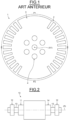
- Figure 1 illustrates a radial section of the magnetic mass of the rotor 1.
- the magnetic mass comprises slots 2 disposed on a diameter of the magnetic mass and extending along the magnetic mass in an axial direction coincident with an axis (A1) coincident with the axis of rotation of the rotor and merging outwards in a radial direction perpendicular to the axis (A1).
- Each slot 2 houses a winding (not represented).
- the slot 2 are arranged to form a first pole P1 and a second pole P2.
- Each pole P1, P2 further comprises a massive area 3 separating two rows of slots 2 of one pole P1, P2.
- the stud members 4 pass through the centre of laminations and connected the two end flanges.
- the rotor 1 is anisotropic so that the shafting of the rotor 1 is asymmetric.
- the stiffness, the mass and the damping of a first area defined by two adjacent rows of the slots of the poles P1, P2 and the massive area 3 are different so that the dynamic differential equation of bending of the rotor 1 has periodic coefficients of stiffness, damping and masses varying periodically two times per revolution of the rotor 1.
- the stiffness, the mass and the damping variations of the rotor 1 may cause gravitational sags when alternatively, the first zone and the massive zone are subject to a gravitational field.
- the rotor 1 may be subjected to self-excited vibrations.
- the self-excited vibrations generate parametric instabilities in certain specific ranges of rotational speed of the rotor 1 depending on the critical speed of the rotor 1, the critical speed being defined with the average value of rotor stiffness and rotor mass.
- the dynamic differential equation of bending of the rotor 1 has in this case periodic coefficients of stiffness, damping and masses varying periodically two times per revolution.
- parametric instabilities may also be generated or amplified by elements outside the rotor 1 for example bearings maintaining the rotor 1 in rotation, foundations on which the bearings rest which are not taken into account for the dimensioning of the striations.
- the invention proposes a system comprising a rotor for a rotating electric machine and bearings maintaining the rotor in rotation, the rotor being a non-through shaft comprising two half-shafts holding tightly a cylindrical magnetic mass comprising a plurality of stacked laminations, circumferential tie rods distributed uniformly over a first diameter of the magnetic mass so as to keep the magnetic mass compacted between the half-shafts, slots regularly disposed on portions of a second diameter of the magnetic mass and extending along the magnetic mass in an axial direction and merging outwards in a radial direction, windings housed in the slots to form at least two magnetic poles, each slot being closed by a wedge.
- the rotor further comprises polar tie rods distributed in an angular sector of each pole with respect to a rotation axis of the rotor so as to keep the magnetic mass compacted between the half-shafts and to stabilize the rotor in rotation according to the bearings, each angular sector comprising the same number of polar tie rods.
- the polar tie rods are distributed uniformly over a first diameter of the magnetic mass in each angular sector.
- the rotor comprises four poles.
- the magnetic mass comprises balancing laminations including a plurality of holes located on an outer circumference of the balancing lamination between the plurality of slots.
- the system comprises a balancing lamination at each end of the magnetic mass and one balancing lamination in the middle of the magnetic mass according to a longitudinal direction of the rotor.
- the bearings comprise active magnetic bearings.
- the bearings comprise lubricated oil bearings.
- Another object of the invention relates to a rotating electric machine comprising a system as defined above.
- Another object of the invention relates to a method for dimensioning a system comprising a two poles rotor for a rotating electric machine and bearings maintained the rotor in rotation, the rotor being a non-through shaft comprising two half-shafts holding tightly a cylindrical magnetic mass comprising a plurality of stacked laminations, circumferential tie rods distributed uniformly over a first diameter of the magnetic mass so as to keep the magnetic mass compacted between the half-shafts, slots regularly disposed on portions of a second diameter of the magnetic mass and extending along the magnetic mass in an axial direction and merging outwards in a radial direction, windings housed in the slots to form the two magnetic poles, each slot being closed by a wedge.
- the method comprises the addition of polar tie rods distributed in an angular sector of each pole with respect to a rotation axis of the rotor so as to keep the magnetic mass compacted between the half-shafts and to stabilize the rotor in rotation according to the bearings, each angular sector comprising the same number of polar tie rods.
- the addition of polar tie rods comprises:
- a new configuration of polar tie rods is determined and steps (b) to (d) are repeated until the rotor is considered as stable.
- the determination of the first rotation speed dependant equivalent stiffness matrix, the second rotation speed dependant equivalent stiffness matrix, the first mass matrix and the second mass matrix comprise:
- determining an interval of unstable rotation speeds comprises determining an average circular natural pulsation and a rotor asymmetric coefficient from the first and second rotation speed dependant equivalent stiffness matrices, and the first and second mass matrices,
- the rotor 11 and the two bearings 12 form a system.
- the bearings 12 comprise magnetic active bearings.
- the bearings 12 comprise lubricated oil bearing s.
- the rotor 11 is a wounded rotor comprising windings and comprises an axis (A) coincident with the axis of rotation of the rotor 11.
- the rotor 11 is a non-through shaft comprising two half-shafts 13 holding tightly a cylindrical magnetic mass 14 comprising a plurality of stacked laminations.
- the two half-shafts 13 are identical.
- the two half-shafts 13 are different.
- Figures 3, 4 and 5 illustrate respectively a view, an exploded view and a radial section of an example of a magnetic mass 14 of the rotor 11.
- the rotor 11 comprises circumferential tie rods 15 distributed uniformly over a first diameter of the magnetic mass 14 and maintaining the stacked laminations of the magnetic mass 14 compacted between the two half-shafts 13.
- the magnetic mass 14 comprises slots 16 housing windings 17 and disposed in rows on portions 18, 19, 20, 21 of a second diameter of the magnetic mass 14.
- the slots 16 extend along the magnetic mass 14 in an axial direction and merge outwards in a radial direction of the rotor 11 so that the slots 16 and the windings 17 form two magnetic poles P10, P11.
- Each slot 16 is closed by a wedge 22.
- Each magnetic pole P10, P11 comprises a first portion 18, 20 and a second portion 19, 21 of slots 16 housing windings 17 separated by a massive portion 23, 24.
- the first portion 18 of a first magnetic pole P10 being adjacent to the second portion 21 of the second magnetic pole P11, and the second portion 19 of the first magnetic pole P10 being adjacent to the first portion 20 of the second magnetic pole P11.
- the magnetic mass 14 comprises two identical stacks of laminations 24, 25 and balancing laminations 26, 27, 28 including a plurality of holes located on an outer circumference of the balancing lamination between the plurality of slots 16.
- the thickness of the balancing laminations 26, 27, 28 have a thickness greater than the thickness of the stacked laminations.
- the number and thickness of balancing laminations 26, 27, 28 and the number of holes in the balancing laminations 26, 26, 28 are selected to provide adequate balance capability over the entire speed range over which the rotor 11 is used in service.
- the magnetic mass 14 comprises tree balancing laminations 26, 27, 28, a first and a second balancing laminations 26, 27 being at each end of the magnetic mass 14, and the third balancing laminations 28 being in the middle of the magnetic mass 14 separating the two stacks of laminations 24, 25.
- the rotor 11 further comprises polar tie rods 29 distributed in an angular sector of each pole with respect to the rotation axis (A) of the rotor 11 so as to keep the magnetic mass compacted between the half-shafts 13 and to stabilize the rotor 11 in rotation according to the bearings 12.
- Each angular sector comprises the same number of polar tie rods 29.
- each pole P10, P11 covers the massive portion 23, 24 of each pole P10, P11.
- the location, the diameter, the number of polar tie rods and the pretension of the polar tie rods 29 are determined to compensate the anisotropy of the rotor 11 in the range of used of the machine 10.
- polar tie rods 29 in the rotor 11 permits to minimize the rotor 11 asymmetries and avoid instabilities of the rotor 11 in the range of use.
- the polar tie rods 29 are distributed uniformly in the massive portions 23, 24 over two diameters of the magnetic mass 14.
- the polar tie rods 29 may be distributed in the massive portions 23, 24 over one or more than two diameters of the magnetic mass 14.
- the rotor 11 may comprise four magnetic poles.
- Figure 7 illustrates a dynamic model of the rotor 11 maintained in rotation by the bearings 12 in a fix coordinate system (O, X, Y).
- the anisotropic rotor 11 comprises an orthogonal rotating coordinate system (G, ⁇ , ⁇ ) defining an angle ⁇ equal to the time t multiplied by the rotation speed ⁇ of the rotor 11.
- the origin G is juxtaposed with the gravity centre of the rotor 11.
- the axis ⁇ separates the first and second portions 18, 19 of the first magnetic pole P10 and the first and second portions 20, 21 of the second magnetic pole P11.
- the axis ⁇ goes through the centre of the massive portions 23, 24 of the magnetic poles P10, P11.
- the first and second portions 18, 19, 20, 21 of the magnetic poles P10, P11 are represented by a mass matrix M ⁇ , a stiffness matrix K R ⁇ and an equivalent damping matrix D1
- the massive portions 23, 24 of the magnetic poles P10, P11 are represented by a mass matrix M ⁇ , a stiffness matrix K R ⁇ , and an equivalent damping matrix D2.
- the bearings 12 are represented by a stiffness coefficient K B along the X and Y, and a damping coefficient D B along the X and Y axis.
- stiffness matrices K R ⁇ , K R ⁇ , and the equivalent damping matrices D1, D2, the stiffness coefficient K B and damping coefficient D B are dependent on the rotation speed ⁇ of the rotor 11.
- polar tie rods 29 comprising a predetermined number of polar tie rods, a predetermined location of polar tie rods in each angular sector and a predetermined mechanical pretension of the polar tie rods is defined, for example as illustrated on figures 2 to 6 .
- step 31 an interval INT of unstable rotation speeds in which the rotor 11 maintained in rotation by the bearings 12 may be unstable is determined.
- the mass of the rotor 11 and the stiffness of the rotor 11 is dependent on the value of the angle ⁇ in the fundamental equation of dynamics.
- K ⁇ being a second rotation speed dependant equivalent stiffness matrice.
- An average circular natural pulsation ⁇ 0 and a rotor asymmetric coefficient ⁇ are defined.
- ⁇ 0 2 ⁇ ⁇ 2 + ⁇ ⁇ 2 2
- the rotation speed dependant equivalent stiffness matrix K R ⁇ and the first mass matrix M ⁇ are determined from a first rotor model.
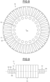
- Figure 8 illustrates an example of a section of the magnetic mass of the first rotor model.
- the first rotor model differs from the model of the rotor 11 in that the slots 16 are regularly disposed on the second diameter of the magnetic mass.
- the slots 16 house the windings 17 and are closed by the wedges 22.
- the first rotor model is isotropic so that an available algorithm may be used to compute mechanical and dynamical features of the first rotor model, for example using an available finite element analysis algorithm.
- the first rotor model is axially sliced to obtain slices Si, i being an integer ( figure 9 ).
- Each slice Si of the first model of the rotor is modelled by a beam to simplify the modelling of the first rotor model.
- the finite analysis algorithm is used to determine the free mode frequency F1 of forward precession gyroscopic effect of the first rotor model according to the rotation speed of the first rotor and the first mass matrix M ⁇ of the first rotor model.
- the modelling of the first rotor model in beams permits to simplify the computation of the free mode frequency F1 of forward precession gyroscopic effect and the first mass matrix.
- K R ⁇ 2 ⁇ F 1
- the second rotor model differs from the model of the rotor 11 in that the angular sectors of the magnetic poles P10, P11 are duplicated on the full periphery of the rotor so that polar tie rods 29 are regularly disposed on a full radial section of the second rotor model.
- FIG. 10 An example of the second rotor model is illustrated on figure 10 .
- the second rotor model is sliced and each slice is modelled by a beam.
- the finite analysis algorithm is used to determine the free mode frequency F2 of forward precession gyroscopic effect of the second rotor model according to the rotation speed of the second rotor model and the second mass matrix M ⁇ of the second rotor model.
- the rotation speed of the first and second rotor models and the rotor 11 is equal and is defined by a predetermined speed interval, the rotation speed varying to cover the full predetermined speed interval.
- K R ⁇ 2 ⁇ F 2
- an absolute difference matrix DIFF between a first rotation speed dependent equivalent damping matrix D1 and a second rotation speed dependent equivalent damping matrix D2 is determined.
- step 33 the absolute difference matrix DIFF is compared to the rotation speed dependent damping matrix D B of the bearings 12.
- the rotor 11 is considered as unstable.
- step 30 A new configuration of polar tie rods is determined.
- the disclosed method permits to enhance the dynamic of the rotor 11 by adding polar tie rods.
Landscapes
- Engineering & Computer Science (AREA)
- Power Engineering (AREA)
- Manufacturing & Machinery (AREA)
- Iron Core Of Rotating Electric Machines (AREA)
Abstract
Description
- The present invention concerns systems comprising non-through shaft rotors maintained in rotation by bearings and a method for dimensioning such systems.
- Document
US2011/0080068 discloses a two poles rotor comprising a magnetic pass including a plurality of stacked laminations, the magnetic mass being tightly held between two end flanges and stud members. - The stud members pass through the centre of laminations and connected the two end flanges.
-
Figure 1 illustrates a radial section of the magnetic mass of therotor 1. - The magnetic mass comprises
slots 2 disposed on a diameter of the magnetic mass and extending along the magnetic mass in an axial direction coincident with an axis (A1) coincident with the axis of rotation of the rotor and merging outwards in a radial direction perpendicular to the axis (A1). - Each
slot 2 houses a winding (not represented). - The
slot 2 are arranged to form a first pole P1 and a second pole P2. - Each pole P1, P2 further comprises a
massive area 3 separating two rows ofslots 2 of one pole P1, P2. - The
stud members 4 pass through the centre of laminations and connected the two end flanges. - Generally, the
rotor 1 is anisotropic so that the shafting of therotor 1 is asymmetric. - The stiffness, the mass and the damping of a first area defined by two adjacent rows of the slots of the poles P1, P2 and the
massive area 3 are different so that the dynamic differential equation of bending of therotor 1 has periodic coefficients of stiffness, damping and masses varying periodically two times per revolution of therotor 1. - The stiffness, the mass and the damping variations of the
rotor 1 may cause gravitational sags when alternatively, the first zone and the massive zone are subject to a gravitational field. - The
rotor 1 may be subjected to self-excited vibrations. - The self-excited vibrations generate parametric instabilities in certain specific ranges of rotational speed of the
rotor 1 depending on the critical speed of therotor 1, the critical speed being defined with the average value of rotor stiffness and rotor mass. The dynamic differential equation of bending of therotor 1 has in this case periodic coefficients of stiffness, damping and masses varying periodically two times per revolution. - In order to reduce the anisotropy of the
rotor 1, circumferential striations are machined on the surface of the magnetic mass. - However, parametric instabilities may also be generated or amplified by elements outside the
rotor 1 for example bearings maintaining therotor 1 in rotation, foundations on which the bearings rest which are not taken into account for the dimensioning of the striations. - It is therefore proposed to remedy the disadvantages related to the method to minimize the anisotropy of rotors according to the prior art with an improved dimensioning method taking into account elements connected the rotors.
- In view of the foregoing the invention proposes a system comprising a rotor for a rotating electric machine and bearings maintaining the rotor in rotation, the rotor being a non-through shaft comprising two half-shafts holding tightly a cylindrical magnetic mass comprising a plurality of stacked laminations, circumferential tie rods distributed uniformly over a first diameter of the magnetic mass so as to keep the magnetic mass compacted between the half-shafts, slots regularly disposed on portions of a second diameter of the magnetic mass and extending along the magnetic mass in an axial direction and merging outwards in a radial direction, windings housed in the slots to form at least two magnetic poles, each slot being closed by a wedge.
- The rotor further comprises polar tie rods distributed in an angular sector of each pole with respect to a rotation axis of the rotor so as to keep the magnetic mass compacted between the half-shafts and to stabilize the rotor in rotation according to the bearings, each angular sector comprising the same number of polar tie rods.
- Preferably, the polar tie rods are distributed uniformly over a first diameter of the magnetic mass in each angular sector.
- Advantageously, the rotor comprises four poles.
- Preferably, the magnetic mass comprises balancing laminations including a plurality of holes located on an outer circumference of the balancing lamination between the plurality of slots.
- Advantageously, the system comprises a balancing lamination at each end of the magnetic mass and one balancing lamination in the middle of the magnetic mass according to a longitudinal direction of the rotor.
- Preferably, the bearings comprise active magnetic bearings.
- Advantageously, the bearings comprise lubricated oil bearings.
- Another object of the invention relates to a rotating electric machine comprising a system as defined above.
- Another object of the invention relates to a method for dimensioning a system comprising a two poles rotor for a rotating electric machine and bearings maintained the rotor in rotation, the rotor being a non-through shaft comprising two half-shafts holding tightly a cylindrical magnetic mass comprising a plurality of stacked laminations, circumferential tie rods distributed uniformly over a first diameter of the magnetic mass so as to keep the magnetic mass compacted between the half-shafts, slots regularly disposed on portions of a second diameter of the magnetic mass and extending along the magnetic mass in an axial direction and merging outwards in a radial direction, windings housed in the slots to form the two magnetic poles, each slot being closed by a wedge.
- The method comprises the addition of polar tie rods distributed in an angular sector of each pole with respect to a rotation axis of the rotor so as to keep the magnetic mass compacted between the half-shafts and to stabilize the rotor in rotation according to the bearings, each angular sector comprising the same number of polar tie rods.
- Preferably, the addition of polar tie rods comprises:
- (a) determining a configuration of polar tie rods comprising a predetermined number of polar tie rods, a predetermined location of polar tie rods in each angular sector and a predetermined mechanical pretension of the polar tie rods,
- (b) determining an interval of unstable rotation speeds in which the rotor maintained in rotation by the bearings may be unstable according to a first rotation speed dependant equivalent stiffness matrix, a second rotation speed dependant equivalent stiffness matrix, a first mass matrix and a second mass matrix, the first rotation speed dependant equivalent stiffness matrix and the first mass matrix being determined from a first rotor model, the second rotation speed dependant equivalent stiffness matrix and the second mass matrix being determined from a second rotor model, the first rotor model being determined according to the slots, the windings, the wedges and the circumferential tie rods and the second rotor model being determined according to the circumferential tie rods and the polar tie rods,
- (c) determining an absolute difference matrix between a first rotation speed dependent equivalent damping matrix and a second rotation speed dependent equivalent damping matrix, the first rotation speed dependent equivalent damping matrix being dependant of the first mass matrix and the first rotation speed dependent equivalent stiffness matrix and the second rotation speed dependent equivalent damping matrix being dependant of the second mass matrix and the second rotation speed dependent equivalent stiffness matrix,
- (d) comparing the absolute difference matrix to rotation speed dependent damping matrix of the bearings,
- Advantageously, if the rotor is considered as instable, a new configuration of polar tie rods is determined and steps (b) to (d) are repeated until the rotor is considered as stable.
- Preferably, the determination of the first rotation speed dependant equivalent stiffness matrix, the second rotation speed dependant equivalent stiffness matrix, the first mass matrix and the second mass matrix comprise:
- defining the first rotor model in which the slots are regularly disposed on the second diameter of the magnetic mass, the slots housing the windings and being closed by the wedges,
- determining the free mode frequency of forward precession gyroscopic effect of the first rotor according to the rotation speed of the first rotor,
- determining the first mass matrix of the first rotor,
- determining the first rotor stiffness matrix according to the free mode frequency of forward precession gyroscopic effect of the first rotor and the first mass matrix,
- defining the second rotor model in which the angular sectors are duplicated on the full periphery of the second rotor model so that polar tie rods are regularly disposed on a full radial section of the second rotor model,
- determining the free mode frequency of forward precession gyroscopic effect according the rotation speed of the second rotor,
- determining a second mass matrix of the second rotor,
- determining the second rotor stiffness matrix according to the free mode frequency of forward precession gyroscopic effect of the second rotor and the second mass matrix,
- Advantageously, determining an interval of unstable rotation speeds comprises determining an average circular natural pulsation and a rotor asymmetric coefficient from the first and second rotation speed dependant equivalent stiffness matrices, and the first and second mass matrices,
- the lower bound of the interval being equal to the average circular natural pulsation multiplied by square root of one minus the rotor asymmetric coefficient, and
- the upper bound of the interval being equal to the average circular natural pulsation multiplied by square root of one plus the rotor asymmetric coefficient.
- Other characteristics and advantages of the invention will emerge on reading the following description of embodiments of the invention, provided solely by way of non-limiting examples and with reference to the drawings in which:
-
Figure 1 illustrates a section of a two poles rotor according to the prior art, -
Figure 2 illustrates an example of a rotary electrical machine according to the invention, -
Figures 3, 4 and5 illustrate an example of a magnetic mass of the rotary electrical machine according to the invention, -
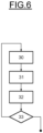
Figure 6 illustrates an example of a method for dimensioning a system according to the invention, -
Figure 7 illustrates an example of a dynamic model of the system according to the invention, -
Figure 8 illustrates an example of a section of a first rotor model according to the invention, -
Figure 9 illustrates an example of modelling of the first rotor model according to the invention, and -
Figure 10 illustrates an example of a section of a second rotor model according to the invention. -
Figure 2 illustrates an example of a rotaryelectrical machine 10 comprising a twopoles rotor 11 maintained in rotation by twobearings 12. - The
rotor 11 and the twobearings 12 form a system. - The
bearings 12 comprise magnetic active bearings. - In another embodiment, the
bearings 12 comprise lubricated oil bearing s. - The
rotor 11 is a wounded rotor comprising windings and comprises an axis (A) coincident with the axis of rotation of therotor 11. - The
rotor 11 is a non-through shaft comprising two half-shafts 13 holding tightly a cylindricalmagnetic mass 14 comprising a plurality of stacked laminations. - The two half-
shafts 13 are identical. - In another embodiment, the two half-
shafts 13 are different. -
Figures 3, 4 and5 illustrate respectively a view, an exploded view and a radial section of an example of amagnetic mass 14 of therotor 11. - The
rotor 11 comprisescircumferential tie rods 15 distributed uniformly over a first diameter of themagnetic mass 14 and maintaining the stacked laminations of themagnetic mass 14 compacted between the two half-shafts 13. - The
magnetic mass 14 comprisesslots 16housing windings 17 and disposed in rows onportions magnetic mass 14. - The
slots 16 extend along themagnetic mass 14 in an axial direction and merge outwards in a radial direction of therotor 11 so that theslots 16 and thewindings 17 form two magnetic poles P10, P11. - Each
slot 16 is closed by awedge 22. - Each magnetic pole P10, P11 comprises a
first portion second portion slots 16housing windings 17 separated by amassive portion - The
first portion 18 of a first magnetic pole P10 being adjacent to thesecond portion 21 of the second magnetic pole P11, and thesecond portion 19 of the first magnetic pole P10 being adjacent to thefirst portion 20 of the second magnetic pole P11. - The
magnetic mass 14 comprises two identical stacks oflaminations laminations slots 16. - The thickness of the balancing
laminations - The number and thickness of balancing
laminations laminations rotor 11 is used in service. - As illustrated, the
magnetic mass 14 comprisestree balancing laminations second balancing laminations magnetic mass 14, and thethird balancing laminations 28 being in the middle of themagnetic mass 14 separating the two stacks oflaminations - The
rotor 11 further comprisespolar tie rods 29 distributed in an angular sector of each pole with respect to the rotation axis (A) of therotor 11 so as to keep the magnetic mass compacted between the half-shafts 13 and to stabilize therotor 11 in rotation according to thebearings 12. - Each angular sector comprises the same number of
polar tie rods 29. - The angular sector of each pole P10, P11 covers the
massive portion - The location, the diameter, the number of polar tie rods and the pretension of the
polar tie rods 29 are determined to compensate the anisotropy of therotor 11 in the range of used of themachine 10. - The addition of
polar tie rods 29 in therotor 11 permits to minimize therotor 11 asymmetries and avoid instabilities of therotor 11 in the range of use. - In the following, a method for dimensioning the system comprising the two
poles rotor 11 andbearings 12 is exposed. - The
polar tie rods 29 are distributed uniformly in themassive portions magnetic mass 14. - In another embodiment, the
polar tie rods 29 may be distributed in themassive portions magnetic mass 14. - In another embodiment, the
rotor 11 may comprise four magnetic poles. - As the
rotor 11 comprising four magnetic poles is intrinsically stable, an example of a method for dimensioning the system comprising the twopoles rotor 11 and thebearings 12 maintaining therotor 11 in rotation by adding thepolar tie rods 29 is presented onfigure 6 . -
Figure 7 illustrates a dynamic model of therotor 11 maintained in rotation by thebearings 12 in a fix coordinate system (O, X, Y). - The
anisotropic rotor 11 comprises an orthogonal rotating coordinate system (G, ξ, η) defining an angle θ equal to the time t multiplied by the rotation speed Ω of therotor 11. - The origin G is juxtaposed with the gravity centre of the
rotor 11. The axis ξ separates the first andsecond portions second portions massive portions - As the
rotor 11 is anisotropic, the first andsecond portions massive portions - To simplify the explanations, the
bearings 12 are represented by a stiffness coefficient KB along the X and Y, and a damping coefficient DB along the X and Y axis. - The stiffness matrices KRξ, KRη, and the equivalent damping matrices D1, D2, the stiffness coefficient KB and damping coefficient DB are dependent on the rotation speed Ω of the
rotor 11. - During a step 30 (
figure 6 ), a configuration ofpolar tie rods 29 comprising a predetermined number of polar tie rods, a predetermined location of polar tie rods in each angular sector and a predetermined mechanical pretension of the polar tie rods is defined, for example as illustrated onfigures 2 to 6 . - In
step 31, an interval INT of unstable rotation speeds in which therotor 11 maintained in rotation by thebearings 12 may be unstable is determined. - As the
rotor 11 is anisotropic, the mass of therotor 11 and the stiffness of therotor 11 is dependent on the value of the angle θ in the fundamental equation of dynamics. - According to the generalized Mathieu's equation, the own pulsation ωξ of the system according to the axis ξ is equal to:


- Kξ being a first rotation speed dependant equivalent stiffness matrice.
- The own pulsation ωη of the system according to the axis η is equal to:


- Kη being a second rotation speed dependant equivalent stiffness matrice.
- An average circular natural pulsation ω0 and a rotor asymmetric coefficient µ are defined.
- The average circular natural pulsation ω0 is equal to:

- The rotor asymmetric coefficient µ is equal to

- The interval INT is equal to:

- The rotation speed dependant equivalent stiffness matrix KRξ and the first mass matrix Mξ are determined from a first rotor model.
-
Figure 8 illustrates an example of a section of the magnetic mass of the first rotor model. - The first rotor model differs from the model of the
rotor 11 in that theslots 16 are regularly disposed on the second diameter of the magnetic mass. Theslots 16 house thewindings 17 and are closed by thewedges 22. - The first rotor model is isotropic so that an available algorithm may be used to compute mechanical and dynamical features of the first rotor model, for example using an available finite element analysis algorithm.
- To determine the rotation speed dependant equivalent stiffness matrix KRξ and the first mass matrix Mξ, the first rotor model is axially sliced to obtain slices Si, i being an integer (
figure 9 ). - Each slice Si of the first model of the rotor is modelled by a beam to simplify the modelling of the first rotor model.
- The finite analysis algorithm is used to determine the free mode frequency F1 of forward precession gyroscopic effect of the first rotor model according to the rotation speed of the first rotor and the first mass matrix Mξ of the first rotor model.
- The modelling of the first rotor model in beams permits to simplify the computation of the free mode frequency F1 of forward precession gyroscopic effect and the first mass matrix.
- The rotation speed dependant equivalent stiffness matrix KRξ is equal to:

- The second rotor model differs from the model of the
rotor 11 in that the angular sectors of the magnetic poles P10, P11 are duplicated on the full periphery of the rotor so thatpolar tie rods 29 are regularly disposed on a full radial section of the second rotor model. - An example of the second rotor model is illustrated on
figure 10 . - Analogously to the first rotor model, the second rotor model is sliced and each slice is modelled by a beam.
- The finite analysis algorithm is used to determine the free mode frequency F2 of forward precession gyroscopic effect of the second rotor model according to the rotation speed of the second rotor model and the second mass matrix Mη of the second rotor model.
- The rotation speed of the first and second rotor models and the
rotor 11 is equal and is defined by a predetermined speed interval, the rotation speed varying to cover the full predetermined speed interval. - The rotation speed dependant equivalent stiffness matrix KRη is equal to:

- During step 32 (
figure 6 ), an absolute difference matrix DIFF between a first rotation speed dependent equivalent damping matrix D1 and a second rotation speed dependent equivalent damping matrix D2 is determined. - The first rotation speed dependent equivalent damping matrix D1 is equal to:
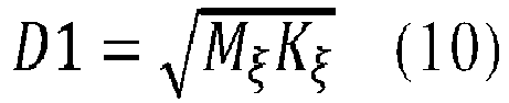
- The second rotation speed dependent equivalent damping matrix D2 is equal to:


- In
step 33, the absolute difference matrix DIFF is compared to the rotation speed dependent damping matrix DB of thebearings 12. - If the nominal rotation speed of the rotor is in the interval of unstable rotation speeds INT and a value of the absolute difference matrix DIFF is greater than the corresponding value of the speed dependent damping matrix DB of the bearings, the
rotor 11 is considered as unstable. - It continues to step 30. A new configuration of polar tie rods is determined.
- If the nominal rotation speed of the rotor is outside the interval of unstable rotation speeds INT or any value of the absolute difference matrix DIFF is greater than the corresponding value of the speed dependent damping matrix of the bearings, the rotor being considered as stable.
- The design of the
rotor 11 is kept. - The disclosed method permits to enhance the dynamic of the
rotor 11 by adding polar tie rods.
Claims (13)
- System comprising a rotor (11) for a rotating electric machine (10) and bearings (12) maintaining the rotor in rotation, the rotor being a non-through shaft comprising two half-shafts (13) holding tightly a cylindrical magnetic mass (14) comprising a plurality of stacked laminations, circumferential tie rods (15) distributed uniformly over a first diameter of the magnetic mass so as to keep the magnetic mass compacted between the half-shafts, slots (16) regularly disposed on portions of a second diameter of the magnetic mass and extending along the magnetic mass in an axial direction and merging outwards in a radial direction, windings (17) housed in the slots to form at least two magnetic poles (P10, P11), each slot being closed by a wedge (22), characterized in that the rotor further comprises polar tie rods (29) distributed in an angular sector of each pole with respect to a rotation axis of the rotor so as to keep the magnetic mass compacted between the half-shafts and to stabilize the rotor in rotation according to the bearings, each angular sector comprising the same number of polar tie rods.
- System according to claim 1, in which the polar tie rods (29) are distributed uniformly over a first diameter of the magnetic mass in each angular sector.
- System according to claim 1 or 2, in which the rotor comprises four poles.
- System according to any of claims 1 to 3, in which the magnetic mass comprises balancing laminations (26, 27, 28) including a plurality of holes located on an outer circumference of the balancing lamination between the plurality of slots (16).
- System according to claim 4, comprising a balancing lamination (26, 27) at each end of the magnetic mass and one balancing lamination (28) in the middle of the magnetic mass (14) according to a longitudinal direction of the rotor.
- System according to any of claims 1 to 5, in which the bearings (12) comprise active magnetic bearings.
- System according to any of claims 1 to 5, in which the bearings (12) comprise lubricated oil bearings.
- Rotating electric machine (10) comprising a system according to any of claims 1 to 7.
- Method for dimensioning a system comprising a two poles rotor (11) for a rotating electric machine (10) and bearings (12) maintained the rotor in rotation, the rotor being a non-through shaft comprising two half-shafts (13) holding tightly a cylindrical magnetic mass (14) comprising a plurality of stacked laminations, circumferential tie rods (15) distributed uniformly over a first diameter of the magnetic mass so as to keep the magnetic mass compacted between the half-shafts, slots (16) regularly disposed on portions of a second diameter of the magnetic mass and extending along the magnetic mass in an axial direction and merging outwards in a radial direction, windings (17) housed in the slots to form the two magnetic poles (P10, P11), each slot being closed by a wedge (22), characterized in that the method comprises the addition of polar tie rods (29) distributed in an angular sector of each pole with respect to a rotation axis of the rotor so as to keep the magnetic mass compacted between the half-shafts and to stabilize the rotor in rotation according to the bearings, each angular sector comprising the same number of polar tie rods.
- Method according to claim 9, in which the addition of polar tie rods comprises:- (a) determining a configuration of polar tie rods (29) comprising a predetermined number of polar tie rods, a predetermined location of polar tie rods in each angular sector and a predetermined mechanical pretension of the polar tie rods,- (b) determining an interval of unstable rotation speeds in which the rotor (11) maintained in rotation by the bearings (12) may be unstable according to a first rotation speed dependant equivalent stiffness matrix, a second rotation speed dependant equivalent stiffness matrix, a first mass matrix and a second mass matrix, the first rotation speed dependant equivalent stiffness matrix and the first mass matrix being determined from a first rotor model, the second rotation speed dependant equivalent stiffness matrix and the second mass matrix being determined from a second rotor model, the first rotor model being determined according to the slots (16), the windings (17), the wedges (22), and the circumferential tie rods (29), and the second rotor model being determined according to the circumferential tie rods and the polar tie rods,- (c) determining an absolute difference matrix between a first rotation speed dependent equivalent damping matrix and a second rotation speed dependent equivalent damping matrix, the first rotation speed dependent equivalent damping matrix being dependant of the first mass matrix and the first rotation speed dependent equivalent stiffness matrix and the second rotation speed dependent equivalent damping matrix being dependant of the second mass matrix and the second rotation speed dependent equivalent stiffness matrix,- (d) comparing the absolute difference matrix to rotation speed dependent damping matrix of the bearings,if the nominal rotation speed of the rotor (11) is in the interval of unstable rotation speeds and a value of the absolute difference matrix is greater than the corresponding value of the speed dependent damping matrix of the bearings (12), the rotor being considered as unstable, and if the nominal rotation speed of the rotor is outside the interval of unstable rotation speeds or any value of the absolute difference matrix is greater than the corresponding value of the speed dependent damping matrix of the bearings, the rotor being considered as stable.
- Method according to claim 10, in which if the rotor (11) is considered as instable, a new configuration of polar tie rods is determined and steps (b) to (d) are repeated until the rotor is considered as stable.
- Method according to claim 10 or 11, in which the determination of the first rotation speed dependant equivalent stiffness matrix, the second rotation speed dependant equivalent stiffness matrix, the first mass matrix and the second mass matrix comprise:- defining the first rotor model in which the slots (16) are regularly disposed on the second diameter of the magnetic mass, the slots housing the windings (17) and being closed by the wedges (22),- determining the free mode frequency of forward precession gyroscopic effect of the first rotor according to the rotation speed of the first rotor,- determining the first mass matrix of the first rotor,- determining the first rotor stiffness matrix according to the free mode frequency of forward precession gyroscopic effect of the first rotor and the first mass matrix,- defining the second rotor model in which the angular sectors are duplicated on the full periphery of the second rotor model so that polar tie rods (29) are regularly disposed on a full radial section of the second rotor model,- determining the free mode frequency of forward precession gyroscopic effect according the rotation speed of the second rotor,- determining a second mass matrix of the second rotor,- determining the second rotor stiffness matrix according to the free mode frequency of forward precession gyroscopic effect of the second rotor and the second mass matrix,the first rotation speed dependant equivalent stiffness matrix being equal to the addition of the first rotor stiffness matrix and a speed dependent stiffness matrix of the bearings, and the second rotation speed dependant equivalent stiffness matrix being equal to the addition of the second rotor stiffness matrix and a speed dependent stiffness matrix of the bearings.
- Method according to any of claims 10 to 12, in which determining an interval of unstable rotation speeds comprises determining an average circular natural pulsation and a rotor asymmetric coefficient from the first and second rotation speed dependant equivalent stiffness matrices, and the first and second mass matrices,the lower bound of the interval being equal to the average circular natural pulsation multiplied by square root of one minus the rotor asymmetric coefficient, andthe upper bound of the interval being equal to the average circular natural pulsation multiplied by square root of one plus the rotor asymmetric coefficient.
Priority Applications (3)
| Application Number | Priority Date | Filing Date | Title |
|---|---|---|---|
| EP21306750.7A EP4195457B1 (en) | 2021-12-10 | 2021-12-10 | System comprising a rotor and bearings and associated method |
| PT213067507T PT4195457T (en) | 2021-12-10 | 2021-12-10 | System comprising a rotor and bearings and associated method |
| PL21306750.7T PL4195457T3 (en) | 2021-12-10 | 2021-12-10 | System comprising a rotor and bearings and associated method |
Applications Claiming Priority (1)
| Application Number | Priority Date | Filing Date | Title |
|---|---|---|---|
| EP21306750.7A EP4195457B1 (en) | 2021-12-10 | 2021-12-10 | System comprising a rotor and bearings and associated method |
Publications (2)
| Publication Number | Publication Date |
|---|---|
| EP4195457A1 true EP4195457A1 (en) | 2023-06-14 |
| EP4195457B1 EP4195457B1 (en) | 2025-12-10 |
Family
ID=80034959
Family Applications (1)
| Application Number | Title | Priority Date | Filing Date |
|---|---|---|---|
| EP21306750.7A Active EP4195457B1 (en) | 2021-12-10 | 2021-12-10 | System comprising a rotor and bearings and associated method |
Country Status (3)
| Country | Link |
|---|---|
| EP (1) | EP4195457B1 (en) |
| PL (1) | PL4195457T3 (en) |
| PT (1) | PT4195457T (en) |
Cited By (1)
| Publication number | Priority date | Publication date | Assignee | Title |
|---|---|---|---|---|
| WO2025112797A1 (en) * | 2023-11-30 | 2025-06-05 | 中车永济电机有限公司 | Permanent magnet electric motor, electric motor rotor system, and manufacturing method therefor |
Citations (3)
| Publication number | Priority date | Publication date | Assignee | Title |
|---|---|---|---|---|
| US2064033A (en) * | 1934-08-15 | 1936-12-15 | Westinghouse Electric & Mfg Co | Turbine generator rotor |
| US4510679A (en) * | 1983-08-17 | 1985-04-16 | Sundstrand Corporation | Method of refurbishing a high speed rotor |
| US20110080068A1 (en) | 2009-10-06 | 2011-04-07 | General Electric Company | Laminated generator rotor structure and related method |
-
2021
- 2021-12-10 PT PT213067507T patent/PT4195457T/en unknown
- 2021-12-10 EP EP21306750.7A patent/EP4195457B1/en active Active
- 2021-12-10 PL PL21306750.7T patent/PL4195457T3/en unknown
Patent Citations (3)
| Publication number | Priority date | Publication date | Assignee | Title |
|---|---|---|---|---|
| US2064033A (en) * | 1934-08-15 | 1936-12-15 | Westinghouse Electric & Mfg Co | Turbine generator rotor |
| US4510679A (en) * | 1983-08-17 | 1985-04-16 | Sundstrand Corporation | Method of refurbishing a high speed rotor |
| US20110080068A1 (en) | 2009-10-06 | 2011-04-07 | General Electric Company | Laminated generator rotor structure and related method |
Cited By (1)
| Publication number | Priority date | Publication date | Assignee | Title |
|---|---|---|---|---|
| WO2025112797A1 (en) * | 2023-11-30 | 2025-06-05 | 中车永济电机有限公司 | Permanent magnet electric motor, electric motor rotor system, and manufacturing method therefor |
Also Published As
| Publication number | Publication date |
|---|---|
| PL4195457T3 (en) | 2026-04-20 |
| EP4195457B1 (en) | 2025-12-10 |
| PT4195457T (en) | 2026-01-30 |
Similar Documents
| Publication | Publication Date | Title |
|---|---|---|
| US7626309B2 (en) | Method of balancing an embedded permanent magnet motor rotor | |
| US11239727B2 (en) | Electrical machine with a rotor having a cavity for the dynamic balancing of the rotor | |
| US8051710B2 (en) | Method and apparatus for balancing a rotor | |
| US4633113A (en) | Side plate construction for permanent magnet rotor | |
| BR112014018852B1 (en) | ENGINE AND VIBRATION REDUCTION METHOD FOR ONE ENGINE | |
| EP4195457B1 (en) | System comprising a rotor and bearings and associated method | |
| US10778062B2 (en) | Electric machine and method for dynamically balancing the rotor of said electric machine | |
| KR102084999B1 (en) | Rotor for electric machine and manufacturing method of rotor | |
| CN104508957B (en) | End cap, motor for motor and the method for assembling motor | |
| JP2018196320A (en) | Rotor | |
| US20260039160A1 (en) | Electric machine with permanent magnet rotor | |
| JP2000316243A (en) | Rotor magnet fixing method and rotor | |
| Hofmann et al. | In-line strategies and methods to reduce balancing efforts within rotor production for electric drives | |
| CN113497500A (en) | Method for determining the size of a rotor, associated rotor and motor-compressor unit | |
| Sobra et al. | Analysis of rotor's eccentricity influence on bearing load of induction machine | |
| Asama et al. | Performance improvement of a bearingless motor by rotation about an estimated center of inertia | |
| CN112737205A (en) | Rotor for permanent magnet synchronous rotating motor and balance adjustment method of rotor | |
| WO2021105776A1 (en) | System and method for positive balancing of rotors | |
| EP4586474A1 (en) | Permanent magnet synchronous motor and manufacturing method of permanent magnet synchronous motor | |
| JP2003516105A (en) | Removable automatic tightening field winding block | |
| EP3240162A1 (en) | Double stator rotating electrical machine | |
| Werner et al. | Dynamic analysis due to eccentricity in asynchronous machines | |
| US20210359574A1 (en) | Well Damped or Critically Damped Motor | |
| CN120691632A (en) | Rotor with magnet positioning tab system | |
| JPH0421338A (en) | Bipolar rotor for rotary electric machine |
Legal Events
| Date | Code | Title | Description |
|---|---|---|---|
| PUAI | Public reference made under article 153(3) epc to a published international application that has entered the european phase |
Free format text: ORIGINAL CODE: 0009012 |
|
| STAA | Information on the status of an ep patent application or granted ep patent |
Free format text: STATUS: THE APPLICATION HAS BEEN PUBLISHED |
|
| AK | Designated contracting states |
Kind code of ref document: A1 Designated state(s): AL AT BE BG CH CY CZ DE DK EE ES FI FR GB GR HR HU IE IS IT LI LT LU LV MC MK MT NL NO PL PT RO RS SE SI SK SM TR |
|
| STAA | Information on the status of an ep patent application or granted ep patent |
Free format text: STATUS: REQUEST FOR EXAMINATION WAS MADE |
|
| 17P | Request for examination filed |
Effective date: 20231120 |
|
| RBV | Designated contracting states (corrected) |
Designated state(s): AL AT BE BG CH CY CZ DE DK EE ES FI FR GB GR HR HU IE IS IT LI LT LU LV MC MK MT NL NO PL PT RO RS SE SI SK SM TR |
|
| STAA | Information on the status of an ep patent application or granted ep patent |
Free format text: STATUS: EXAMINATION IS IN PROGRESS |
|
| 17Q | First examination report despatched |
Effective date: 20250703 |
|
| REG | Reference to a national code |
Ref country code: DE Ref legal event code: R079 Free format text: PREVIOUS MAIN CLASS: H02K0001240000 Ipc: H02K0015165000 Ref document number: 602021044033 Country of ref document: DE |
|
| GRAP | Despatch of communication of intention to grant a patent |
Free format text: ORIGINAL CODE: EPIDOSNIGR1 |
|
| STAA | Information on the status of an ep patent application or granted ep patent |
Free format text: STATUS: GRANT OF PATENT IS INTENDED |
|
| GRAS | Grant fee paid |
Free format text: ORIGINAL CODE: EPIDOSNIGR3 |
|
| RIC1 | Information provided on ipc code assigned before grant |
Ipc: H02K 15/165 20250101AFI20250929BHEP Ipc: H02K 1/24 20060101ALI20250929BHEP Ipc: H02K 1/28 20060101ALI20250929BHEP Ipc: H02K 7/00 20060101ALI20250929BHEP Ipc: H02K 19/00 20060101ALI20250929BHEP |
|
| GRAA | (expected) grant |
Free format text: ORIGINAL CODE: 0009210 |
|
| STAA | Information on the status of an ep patent application or granted ep patent |
Free format text: STATUS: THE PATENT HAS BEEN GRANTED |
|
| INTG | Intention to grant announced |
Effective date: 20251010 |
|
| AK | Designated contracting states |
Kind code of ref document: B1 Designated state(s): AL AT BE BG CH CY CZ DE DK EE ES FI FR GB GR HR HU IE IS IT LI LT LU LV MC MK MT NL NO PL PT RO RS SE SI SK SM TR |
|
| REG | Reference to a national code |
Ref country code: CH Ref legal event code: F10 Free format text: ST27 STATUS EVENT CODE: U-0-0-F10-F00 (AS PROVIDED BY THE NATIONAL OFFICE) Effective date: 20251210 Ref country code: GB Ref legal event code: FG4D |
|
| REG | Reference to a national code |
Ref country code: DE Ref legal event code: R096 Ref document number: 602021044033 Country of ref document: DE |
|
| REG | Reference to a national code |
Ref country code: IE Ref legal event code: FG4D |
|
| REG | Reference to a national code |
Ref country code: CH Ref legal event code: R17 Free format text: ST27 STATUS EVENT CODE: U-0-0-R10-R17 (AS PROVIDED BY THE NATIONAL OFFICE) Effective date: 20260109 |
|
| PGFP | Annual fee paid to national office [announced via postgrant information from national office to epo] |
Ref country code: AT Payment date: 20260113 Year of fee payment: 5 |
|
| REG | Reference to a national code |
Ref country code: PT Ref legal event code: SC4A Ref document number: 4195457 Country of ref document: PT Date of ref document: 20260130 Kind code of ref document: T Free format text: AVAILABILITY OF NATIONAL TRANSLATION Effective date: 20260126 |
|
| REG | Reference to a national code |
Ref country code: FI Ref legal event code: FGE Ref country code: CH Ref legal event code: U11 Free format text: ST27 STATUS EVENT CODE: U-0-0-U10-U11 (AS PROVIDED BY THE NATIONAL OFFICE) Effective date: 20260227 |
|
| PGFP | Annual fee paid to national office [announced via postgrant information from national office to epo] |
Ref country code: GB Payment date: 20260225 Year of fee payment: 5 |
|
| PG25 | Lapsed in a contracting state [announced via postgrant information from national office to epo] |
Ref country code: ES Free format text: LAPSE BECAUSE OF FAILURE TO SUBMIT A TRANSLATION OF THE DESCRIPTION OR TO PAY THE FEE WITHIN THE PRESCRIBED TIME-LIMIT Effective date: 20251210 |
|
| REG | Reference to a national code |
Ref country code: LT Ref legal event code: MG9D |
|
| PG25 | Lapsed in a contracting state [announced via postgrant information from national office to epo] |
Ref country code: NO Free format text: LAPSE BECAUSE OF FAILURE TO SUBMIT A TRANSLATION OF THE DESCRIPTION OR TO PAY THE FEE WITHIN THE PRESCRIBED TIME-LIMIT Effective date: 20260310 |
|
| PGFP | Annual fee paid to national office [announced via postgrant information from national office to epo] |
Ref country code: DE Payment date: 20260225 Year of fee payment: 5 |
|
| PG25 | Lapsed in a contracting state [announced via postgrant information from national office to epo] |
Ref country code: HR Free format text: LAPSE BECAUSE OF FAILURE TO SUBMIT A TRANSLATION OF THE DESCRIPTION OR TO PAY THE FEE WITHIN THE PRESCRIBED TIME-LIMIT Effective date: 20251210 |
|
| PGFP | Annual fee paid to national office [announced via postgrant information from national office to epo] |
Ref country code: FI Payment date: 20260227 Year of fee payment: 5 Ref country code: IT Payment date: 20260227 Year of fee payment: 5 |
|
| REG | Reference to a national code |
Ref country code: NL Ref legal event code: MP Effective date: 20251210 |
|
| PG25 | Lapsed in a contracting state [announced via postgrant information from national office to epo] |
Ref country code: RS Free format text: LAPSE BECAUSE OF FAILURE TO SUBMIT A TRANSLATION OF THE DESCRIPTION OR TO PAY THE FEE WITHIN THE PRESCRIBED TIME-LIMIT Effective date: 20260310 |
|
| PGFP | Annual fee paid to national office [announced via postgrant information from national office to epo] |
Ref country code: FR Payment date: 20260220 Year of fee payment: 5 |
|
| PGFP | Annual fee paid to national office [announced via postgrant information from national office to epo] |
Ref country code: PT Payment date: 20260302 Year of fee payment: 5 Ref country code: CH Payment date: 20260227 Year of fee payment: 5 |
|
| PGFP | Annual fee paid to national office [announced via postgrant information from national office to epo] |
Ref country code: PL Payment date: 20260304 Year of fee payment: 5 |
|
| PG25 | Lapsed in a contracting state [announced via postgrant information from national office to epo] |
Ref country code: LV Free format text: LAPSE BECAUSE OF FAILURE TO SUBMIT A TRANSLATION OF THE DESCRIPTION OR TO PAY THE FEE WITHIN THE PRESCRIBED TIME-LIMIT Effective date: 20251210 |
|
| PG25 | Lapsed in a contracting state [announced via postgrant information from national office to epo] |
Ref country code: BG Free format text: LAPSE BECAUSE OF FAILURE TO SUBMIT A TRANSLATION OF THE DESCRIPTION OR TO PAY THE FEE WITHIN THE PRESCRIBED TIME-LIMIT Effective date: 20251210 |
|
| REG | Reference to a national code |
Ref country code: AT Ref legal event code: MK05 Ref document number: 1867222 Country of ref document: AT Kind code of ref document: T Effective date: 20251210 |
|
| PG25 | Lapsed in a contracting state [announced via postgrant information from national office to epo] |
Ref country code: NL Free format text: LAPSE BECAUSE OF FAILURE TO SUBMIT A TRANSLATION OF THE DESCRIPTION OR TO PAY THE FEE WITHIN THE PRESCRIBED TIME-LIMIT Effective date: 20251210 |
|
| PG25 | Lapsed in a contracting state [announced via postgrant information from national office to epo] |
Ref country code: LT Free format text: LAPSE BECAUSE OF FAILURE TO SUBMIT A TRANSLATION OF THE DESCRIPTION OR TO PAY THE FEE WITHIN THE PRESCRIBED TIME-LIMIT Effective date: 20251210 |
|
| PG25 | Lapsed in a contracting state [announced via postgrant information from national office to epo] |
Ref country code: SM Free format text: LAPSE BECAUSE OF FAILURE TO SUBMIT A TRANSLATION OF THE DESCRIPTION OR TO PAY THE FEE WITHIN THE PRESCRIBED TIME-LIMIT Effective date: 20251210 |
|
| PG25 | Lapsed in a contracting state [announced via postgrant information from national office to epo] |
Ref country code: AT Free format text: LAPSE BECAUSE OF FAILURE TO SUBMIT A TRANSLATION OF THE DESCRIPTION OR TO PAY THE FEE WITHIN THE PRESCRIBED TIME-LIMIT Effective date: 20251210 |
|
| PG25 | Lapsed in a contracting state [announced via postgrant information from national office to epo] |
Ref country code: EE Free format text: LAPSE BECAUSE OF FAILURE TO SUBMIT A TRANSLATION OF THE DESCRIPTION OR TO PAY THE FEE WITHIN THE PRESCRIBED TIME-LIMIT Effective date: 20251210 |
|
| PG25 | Lapsed in a contracting state [announced via postgrant information from national office to epo] |
Ref country code: IS Free format text: LAPSE BECAUSE OF FAILURE TO SUBMIT A TRANSLATION OF THE DESCRIPTION OR TO PAY THE FEE WITHIN THE PRESCRIBED TIME-LIMIT Effective date: 20260410 |
|
| PG25 | Lapsed in a contracting state [announced via postgrant information from national office to epo] |
Ref country code: CZ Free format text: LAPSE BECAUSE OF FAILURE TO SUBMIT A TRANSLATION OF THE DESCRIPTION OR TO PAY THE FEE WITHIN THE PRESCRIBED TIME-LIMIT Effective date: 20251210 |
|
| PG25 | Lapsed in a contracting state [announced via postgrant information from national office to epo] |
Ref country code: SK Free format text: LAPSE BECAUSE OF FAILURE TO SUBMIT A TRANSLATION OF THE DESCRIPTION OR TO PAY THE FEE WITHIN THE PRESCRIBED TIME-LIMIT Effective date: 20251210 |
|
| PG25 | Lapsed in a contracting state [announced via postgrant information from national office to epo] |
Ref country code: RO Free format text: LAPSE BECAUSE OF FAILURE TO SUBMIT A TRANSLATION OF THE DESCRIPTION OR TO PAY THE FEE WITHIN THE PRESCRIBED TIME-LIMIT Effective date: 20251210 |
|
| PG25 | Lapsed in a contracting state [announced via postgrant information from national office to epo] |
Ref country code: SE Free format text: LAPSE BECAUSE OF FAILURE TO SUBMIT A TRANSLATION OF THE DESCRIPTION OR TO PAY THE FEE WITHIN THE PRESCRIBED TIME-LIMIT Effective date: 20251210 |