EP4195399A1 - Wound electrode assembly, battery cell, battery and electrical device - Google Patents
Wound electrode assembly, battery cell, battery and electrical device Download PDFInfo
- Publication number
- EP4195399A1 EP4195399A1 EP21955296.5A EP21955296A EP4195399A1 EP 4195399 A1 EP4195399 A1 EP 4195399A1 EP 21955296 A EP21955296 A EP 21955296A EP 4195399 A1 EP4195399 A1 EP 4195399A1
- Authority
- EP
- European Patent Office
- Prior art keywords
- tabs
- width
- tab
- winding
- electrode assembly
- Prior art date
- Legal status (The legal status is an assumption and is not a legal conclusion. Google has not performed a legal analysis and makes no representation as to the accuracy of the status listed.)
- Pending
Links
Images



Classifications
-
- H—ELECTRICITY
- H01—ELECTRIC ELEMENTS
- H01M—PROCESSES OR MEANS, e.g. BATTERIES, FOR THE DIRECT CONVERSION OF CHEMICAL ENERGY INTO ELECTRICAL ENERGY
- H01M10/00—Secondary cells; Manufacture thereof
- H01M10/04—Construction or manufacture in general
- H01M10/0404—Machines for assembling batteries
- H01M10/0409—Machines for assembling batteries for cells with wound electrodes
-
- H—ELECTRICITY
- H01—ELECTRIC ELEMENTS
- H01M—PROCESSES OR MEANS, e.g. BATTERIES, FOR THE DIRECT CONVERSION OF CHEMICAL ENERGY INTO ELECTRICAL ENERGY
- H01M50/00—Constructional details or processes of manufacture of the non-active parts of electrochemical cells other than fuel cells, e.g. hybrid cells
- H01M50/50—Current conducting connections for cells or batteries
- H01M50/531—Electrode connections inside a battery casing
- H01M50/538—Connection of several leads or tabs of wound or folded electrode stacks
-
- H—ELECTRICITY
- H01—ELECTRIC ELEMENTS
- H01M—PROCESSES OR MEANS, e.g. BATTERIES, FOR THE DIRECT CONVERSION OF CHEMICAL ENERGY INTO ELECTRICAL ENERGY
- H01M10/00—Secondary cells; Manufacture thereof
- H01M10/04—Construction or manufacture in general
-
- H—ELECTRICITY
- H01—ELECTRIC ELEMENTS
- H01M—PROCESSES OR MEANS, e.g. BATTERIES, FOR THE DIRECT CONVERSION OF CHEMICAL ENERGY INTO ELECTRICAL ENERGY
- H01M10/00—Secondary cells; Manufacture thereof
- H01M10/04—Construction or manufacture in general
- H01M10/0431—Cells with wound or folded electrodes
-
- H—ELECTRICITY
- H01—ELECTRIC ELEMENTS
- H01M—PROCESSES OR MEANS, e.g. BATTERIES, FOR THE DIRECT CONVERSION OF CHEMICAL ENERGY INTO ELECTRICAL ENERGY
- H01M10/00—Secondary cells; Manufacture thereof
- H01M10/05—Accumulators with non-aqueous electrolyte
- H01M10/052—Li-accumulators
-
- H—ELECTRICITY
- H01—ELECTRIC ELEMENTS
- H01M—PROCESSES OR MEANS, e.g. BATTERIES, FOR THE DIRECT CONVERSION OF CHEMICAL ENERGY INTO ELECTRICAL ENERGY
- H01M10/00—Secondary cells; Manufacture thereof
- H01M10/05—Accumulators with non-aqueous electrolyte
- H01M10/058—Construction or manufacture
- H01M10/0587—Construction or manufacture of accumulators having only wound construction elements, i.e. wound positive electrodes, wound negative electrodes and wound separators
-
- H—ELECTRICITY
- H01—ELECTRIC ELEMENTS
- H01M—PROCESSES OR MEANS, e.g. BATTERIES, FOR THE DIRECT CONVERSION OF CHEMICAL ENERGY INTO ELECTRICAL ENERGY
- H01M50/00—Constructional details or processes of manufacture of the non-active parts of electrochemical cells other than fuel cells, e.g. hybrid cells
- H01M50/20—Mountings; Secondary casings or frames; Racks, modules or packs; Suspension devices; Shock absorbers; Transport or carrying devices; Holders
- H01M50/202—Casings or frames around the primary casing of a single cell or a single battery
-
- H—ELECTRICITY
- H01—ELECTRIC ELEMENTS
- H01M—PROCESSES OR MEANS, e.g. BATTERIES, FOR THE DIRECT CONVERSION OF CHEMICAL ENERGY INTO ELECTRICAL ENERGY
- H01M50/00—Constructional details or processes of manufacture of the non-active parts of electrochemical cells other than fuel cells, e.g. hybrid cells
- H01M50/20—Mountings; Secondary casings or frames; Racks, modules or packs; Suspension devices; Shock absorbers; Transport or carrying devices; Holders
- H01M50/247—Mountings; Secondary casings or frames; Racks, modules or packs; Suspension devices; Shock absorbers; Transport or carrying devices; Holders specially adapted for portable devices, e.g. mobile phones, computers, hand tools or pacemakers
-
- H—ELECTRICITY
- H01—ELECTRIC ELEMENTS
- H01M—PROCESSES OR MEANS, e.g. BATTERIES, FOR THE DIRECT CONVERSION OF CHEMICAL ENERGY INTO ELECTRICAL ENERGY
- H01M50/00—Constructional details or processes of manufacture of the non-active parts of electrochemical cells other than fuel cells, e.g. hybrid cells
- H01M50/20—Mountings; Secondary casings or frames; Racks, modules or packs; Suspension devices; Shock absorbers; Transport or carrying devices; Holders
- H01M50/249—Mountings; Secondary casings or frames; Racks, modules or packs; Suspension devices; Shock absorbers; Transport or carrying devices; Holders specially adapted for aircraft or vehicles, e.g. cars or trains
-
- H—ELECTRICITY
- H01—ELECTRIC ELEMENTS
- H01M—PROCESSES OR MEANS, e.g. BATTERIES, FOR THE DIRECT CONVERSION OF CHEMICAL ENERGY INTO ELECTRICAL ENERGY
- H01M50/00—Constructional details or processes of manufacture of the non-active parts of electrochemical cells other than fuel cells, e.g. hybrid cells
- H01M50/50—Current conducting connections for cells or batteries
- H01M50/531—Electrode connections inside a battery casing
- H01M50/533—Electrode connections inside a battery casing characterised by the shape of the leads or tabs
-
- Y—GENERAL TAGGING OF NEW TECHNOLOGICAL DEVELOPMENTS; GENERAL TAGGING OF CROSS-SECTIONAL TECHNOLOGIES SPANNING OVER SEVERAL SECTIONS OF THE IPC; TECHNICAL SUBJECTS COVERED BY FORMER USPC CROSS-REFERENCE ART COLLECTIONS [XRACs] AND DIGESTS
- Y02—TECHNOLOGIES OR APPLICATIONS FOR MITIGATION OR ADAPTATION AGAINST CLIMATE CHANGE
- Y02E—REDUCTION OF GREENHOUSE GAS [GHG] EMISSIONS, RELATED TO ENERGY GENERATION, TRANSMISSION OR DISTRIBUTION
- Y02E60/00—Enabling technologies; Technologies with a potential or indirect contribution to GHG emissions mitigation
- Y02E60/10—Energy storage using batteries
-
- Y—GENERAL TAGGING OF NEW TECHNOLOGICAL DEVELOPMENTS; GENERAL TAGGING OF CROSS-SECTIONAL TECHNOLOGIES SPANNING OVER SEVERAL SECTIONS OF THE IPC; TECHNICAL SUBJECTS COVERED BY FORMER USPC CROSS-REFERENCE ART COLLECTIONS [XRACs] AND DIGESTS
- Y02—TECHNOLOGIES OR APPLICATIONS FOR MITIGATION OR ADAPTATION AGAINST CLIMATE CHANGE
- Y02P—CLIMATE CHANGE MITIGATION TECHNOLOGIES IN THE PRODUCTION OR PROCESSING OF GOODS
- Y02P70/00—Climate change mitigation technologies in the production process for final industrial or consumer products
- Y02P70/50—Manufacturing or production processes characterised by the final manufactured product
Definitions
- the present application relates to the technical field of batteries, in particular to a wound electrode assembly, a battery cell, a battery, an electrical device, and a method and manufacturing apparatus for the wound electrode assembly.
- lithium-ion batteries are widely used in a vehicle, a portable appliance, a mobile phone, a spacecraft and other fields to provide electric energy for them.
- Embodiments of the present application provide a wound electrode assembly, a battery cell, a battery, an electrical device, and a method and manufacturing apparatus for the wound electrode assembly.
- an embodiment of the present application provides a wound electrode assembly, including: an electrode sheet.
- the electrode sheet includes a winding ending section, the winding ending section is provided with a plurality of first tabs, the plurality of first tabs are laminated, and among the two adjacent first tabs, a width of the first tab close to a winding center of the wound electrode assembly is greater than a width of the first tab away from the winding center.
- the plurality of first tabs are laminated, and among the two adjacent first tabs, the width of the first tab close to the winding center is greater than the width of the first tab away from the winding center.
- the widths of the plurality of first tabs gradually decrease, and after the winding ending section is wound, the amount of misalignment between the two adjacent first tabs is reduced in a width direction of the first tabs, so that the total amount of misalignment shown by the plurality of first tabs is small, the risk of short circuit caused by the large amount of misalignment of the plurality of first tabs in the width direction of the first tabs of the electrode assembly is reduced, and safety performance of a battery cell is improved.
- the total amount of misalignment shown by the plurality of first tabs is small, therefore the same connection region can correspond to more first tabs, which is beneficial to increase a size of the electrode assembly in a thickness direction, and can improve the energy density of the battery cell.
- the electrode sheet further includes a winding start section connected with the winding ending section, the winding start section is provided with a second tab, and the second tab and the plurality of the first tabs are laminated.
- a width of the second tab is greater than or equal to a width of the first tab closest to the winding center among the plurality of first tabs.
- the amount of misalignment of the second tab on the winding start section of the electrode assembly is small in a width direction of the second tab, therefore, the width of the second tab is greater than or equal to the width of the plurality of first tabs, so that the tabs of the electrode assembly may have a good current-carrying capacity and a good heat-dissipating capacity without affecting the total amount of misalignment of the tabs of the electrode assembly.
- the quantity of the second tabs is multiple, the plurality of second tabs are laminated, and the widths of the plurality of second tabs are equal.
- the widths of the plurality of second tabs are equal, which not only facilitates manufacturing, but also enables the tabs to have the good current-carrying capacity and heat-dissipating capacity.
- the quantity of the second tabs is less than or equal to 25.
- the quantity of the second tabs is less than or equal to 25, which can effectively reduce the total amount of misalignment of the first tabs and the second tabs in the width direction of the first tabs, and reduce the risk of the short circuit caused by the large amount of misalignment of the plurality of first tabs in the width direction of the first tabs.
- the quantity of the second tabs is multiple, and the plurality of second tabs are laminated. Among the two adjacent second tabs, the width of the second tab close to the winding center is greater than the width of the second tab away from the winding center.
- the plurality of second tabs are laminated in the same direction as the stacking direction of the plurality of first tabs, and among the two adjacent second tabs, the width of the second tabs close to the winding center is greater than the width of the second tabs away from the winding center. In other words, from the inside to the outside, the widths of the plurality of second tabs gradually decrease, so that the second tabs have the good current-carrying capacity and the good heat-dissipating capacity.
- the first tabs have connection ends and free ends, and the connection ends are connected to one end of the winding ending section in the width direction of the electrode sheet; and the width of each first tab of the plurality of first tabs gradually decreases in a direction from the connection ends to the free ends.
- the width of each first tab gradually decreases to avoid interference with other components.
- the connection strength between the first tabs and the winding ending section is increased.
- a width difference between the two adjacent first tabs is equal.
- the width difference between the two adjacent first tabs is equal. That is, in the direction of the first tabs facing away from the winding center, the widths of the plurality of first tabs decrease linearly, which can reduce the total amount of misalignment of the plurality of first tabs in the width direction of the first tabs, and reduce the risk of the short circuit caused by the large amount of misalignment of the plurality of first tabs in the width direction of the first tabs.
- the width difference between the two adjacent first tabs gradually increases in the direction of the plurality of first tabs facing away from the winding center.
- the width difference between the two adjacent first tabs gradually increases, which can reduce the total amount of misalignment generated by the plurality of first tabs in the width direction of the first tabs, and reduce the risk of the short circuit of the electrode assembly caused by the large amount of misalignment of the plurality of first tabs in the width direction of the first tabs.
- the width difference between the two adjacent first tabs is 0.5mm-4mm in the direction of the plurality of first tabs facing away from the winding center.
- the width difference between the two adjacent first tabs is 0.5mm-4mm, which can effectively reduce the risk of the short circuit caused by the large amount of misalignment of the plurality of first tabs in the width direction of the first tabs, and can further ensure the current-carrying capacity and the heat-dissipating capacity of the first tabs.
- the width difference between the two adjacent first tabs is less than 0.5mm, among the two adjacent first tabs, the width of one first tab away from the winding center is not significantly decreased relative to the width of one first tab close to the winding center, and finally the total amount of misalignment of the plurality of first tabs is not significantly reduced, which cannot effectively reduce the risk of the short circuit caused by the large amount of misalignment of the plurality of first tabs in the width direction of the first tabs.
- the width difference between the two adjacent first tabs is greater than 4 mm, among the two adjacent first tabs, the width of one first tab away from the winding center is decreased too much relative to the width of one first tab close to the winding center, which makes it difficult to ensure the current-carrying capability and heat-dissipating capacity of the first tabs.
- the height of the plurality of first tabs gradually decreases in the direction of the plurality of first tabs facing away from the winding center.
- the height of the plurality of first tabs gradually decreases in the direction of the plurality of first tabs facing away from the winding center. That is, the width and height of the first tabs decrease synchronously, so that the risk of the first tabs are prone to being folded after the width decreases.
- a ratio of the width to the height of each first tab of the plurality of first tabs is the same.
- the ratio of the width to the height of each first tab of the plurality of first tabs is the same. After the width of the first tabs decreases, the height of the first tabs synchronously decreases, which reduces the risk that the first tabs are prone to being folded after the width decreases.
- a distance between the two adjacent first tabs gradually increases in a winding direction of the wound electrode assembly.
- the distance between the two adjacent first tabs gradually increases in the winding direction of the wound electrode assembly, which can reduce the amount of misalignment of the two adjacent first tabs, and thus reduce the risk of the short circuit caused by the large amount of misalignment of the plurality of first tabs in the width direction of the first tabs.
- an embodiment of the present application provides a battery cell, including a case and the wound electrode assembly provided by the embodiment of the first aspect, wherein the wound electrode assembly is accommodated in the case.
- widths of a plurality of first tabs of a winding ending section gradually decrease, and after the winding ending section is wound, the amount of misalignment between the two adjacent first tabs is reduced in a width direction of the first tabs, so that the total amount of misalignment shown by the plurality of first tabs is small, and a risk of a short circuit caused by the large amount of misalignment of the plurality of first tabs in the width direction of the first tabs is reduced.
- the total amount of misalignment shown by the plurality of first tabs is small, therefore the same connection region can correspond to more first tabs, which is beneficial to increase a size of the electrode assembly in a thickness direction, and improves energy density of the battery cell.
- an embodiment of the present application provides a battery, including a box body and the battery cell provided by the embodiment of the second aspect, wherein the battery cell is accommodated in the box body.
- widths of a plurality of first tabs of a winding ending section gradually decrease, and after the winding ending section is wound, the amount of misalignment between the two adjacent first tabs is reduced in a width direction of the first tabs, so that the total amount of misalignment shown by the plurality of first tabs is small, a risk of a short circuit caused by the large amount of misalignment of the plurality of first tabs in the width direction of the first tabs is reduced, and safety performance of the battery can also be improved.
- the total amount of misalignment shown by the plurality of first tabs is small, therefore the same connection region can correspond to more first tabs, which is beneficial to increase a size of the electrode assembly in a thickness direction, and improves energy density of the battery.
- an embodiment of the present application provides an electrical device, including the battery cell provided by the embodiment in the second aspect.
- the total amount of misalignment shown by a plurality of first tabs is small, which reduces a risk of a short circuit caused by the large amount of misalignment of the plurality of first tabs in a width direction of the first tabs, can also improve safety performance of the battery cell, and improves electrical safety of the electrical device.
- the total amount of misalignment shown by the plurality of first tabs is small, therefore the same region can correspond to more first tabs, which is beneficial to increase a size of an electrode assembly in a thickness direction, and improves energy density of the battery cell, so as to meet the larger and longer-term electric energy demands of the electrical device.
- an embodiment of the present application provides a method for manufacturing a wound electrode assembly, including:
- a width of the first tab close to the winding center of the wound electrode assembly is greater than a width of the first tab away from the winding center.
- the electrode sheet is wound around the winding center, so that the plurality of the first tabs are laminated.
- the total amount of misalignment shown by the plurality of first tabs is small, which reduces a risk of a short circuit caused by the large amount of misalignment of the plurality of first tabs in a width direction of the first tabs, can also improve safety performance of a battery cell, and improves electrical safety of an electrical device.
- the total amount of misalignment shown by the plurality of first tabs is small, therefore the same region can correspond to more first tabs, which is beneficial to increase a size of the electrode assembly in a thickness direction, and improves energy density of the battery cell.
- an embodiment of the present application provides a manufacturing apparatus for a wound electrode assembly, including a providing means and an assembling means.
- the providing means is configured to provide an electrode sheet, wherein the electrode sheet includes a winding ending section, and the winding ending section is provided with a plurality of first tabs.
- the assembling means is configured to wind the electrode sheet around a winding center, so that the plurality of the first tabs are laminated. Wherein, among the two adjacent first tabs, a width of the first tab close to the winding center of the wound electrode assembly is greater than a width of the first tab away from the winding center.
- the assembling means winds the electrode sheet around the winding center, so that the plurality of the first tabs are laminated.
- the total amount of misalignment shown by the plurality of first tabs is small, which reduces a risk of a short circuit caused by the large amount of misalignment of the plurality of first tabs in a width direction of the first tabs, can also improve safety performance of a battery cell, and improves electrical safety of an electrical device.
- the total amount of misalignment shown by the plurality of first tabs is small, therefore the same region can correspond to more first tabs, which is beneficial to increase a size of the electrode assembly in a thickness direction, and improves energy density of the battery cell.
- Icon 1000-vehicle; 100-battery; 10-box body; 11-accommodating space; 12-first part; 13-second part; 20-battery cell; 21-case; 21 1-opening; 22-end cap assembly; 221-end cap; 222-first electrode terminal; 223-second electrode terminal; 224-current collecting component; 224a-first current collecting component; 224b-second current collecting part; 225-pressure relief mechanism; 23-electrode assembly; 231-electrode sheet; 2311-positive electrode tab; 2312-negative electrode tab; 23 13 -winding ending section; 23 14- first tab; 23141-connection end; 23142-free end; 2315-winding start section; 2316-second tab; 30-bus component; 200-controller; 300-motor; 2000-manufacturing apparatus for wound electrode assembly; 2100-providing means; 2200-assembling means; A-length direction of electrode assembly; B-axis direction of electrode assembly; C-thickness direction of electrode assembly; D-winding direction;
- the indicated orientation or positional relationship is the orientation or positional relationship shown based on the drawings, or the orientation or positional relationship that is usually placed when the application product is used, or the orientation or positional relationship that is commonly understood by those skilled in the art, and is only for It is only for the convenience of describing the present application and for simplifying the description, but do not indicate or imply that the apparatuses or elements referred to must have particular orientations, be constructed and operated in particular orientations, and therefore cannot be construed as a limitation of the present application.
- the terms “first”, “second” and “third” are only used to differentiate the description, and cannot be construed as indicating or implying relative importance.
- a wound electrode assembly is formed by stacking and winding a positive electrode sheet, a separator and a negative electrode sheet.
- Positive electrode tabs of the positive electrode sheet are laminated, and each positive electrode tab is required to be completely overlapped or the amount of misalignment should be controlled within a certain range.
- Negative electrode tabs of the negative electrode sheet are laminated, and each negative electrode tab is required to be completely overlapped or the amount of misalignment should be controlled within a certain range.
- a winding radius of the electrode sheet becomes larger and larger, resulting in a larger total amount of misalignment shown by the positive electrode tabs and/or the negative electrode tabs.
- the large total amount of misalignment of the tabs will lead to many problems.
- the large total amount of misalignment of the tabs leads to decrease of a distance between the positive electrode tabs and the negative electrode tabs, increase of a risk of a short circuit, and influence on safety of a battery cell.
- the large total amount of misalignment of the tabs leads to a small overlap area between the tabs, which reduces a welding area with other components (such as an electrode terminal, an end cap, and a current collecting component), thereby reducing a current-carrying area, and affecting the safety of battery cell.
- a plurality of first tabs at a winding ending section of an electrode sheet are laminated, and among the two adjacent first tabs, a width of the first tab close to a winding center of the wound electrode assembly is greater than a width of the first tab away from the winding center.
- the widths of the plurality of first tabs gradually decrease, the amount of misalignment between the two adjacent first tabs is reduced, so that the total amount of misalignment shown by the plurality of first tabs is small, and the risk of the short circuit is reduced.
- the total amount of misalignment shown by the plurality of first tabs is small, therefore the same connection region can correspond to more first tabs, which is beneficial to increase a size of the electrode assembly in a thickness direction, and can improve the energy density of the battery cell.
- the electrical device may be a vehicle, a mobile phone, a portable device, a laptop, a ship, a spacecraft, an electric toy, an electric tool, and the like.
- the vehicle may be a fuel vehicle, a gas vehicle or a new energy vehicle.
- the new energy vehicle may be an all-electric vehicle, a hybrid vehicle, an range extended electric vehicle, or the like.
- the spacecraft includes airplanes, rockets, space shuttles, spaceships, and the like.
- the electric toy includes fixed or mobile electric toys, such as game consoles, electric car toys, electric ship toys and electric aircraft toys.
- the electric tool includes metal cutting electric tools, grinding electric tools, assembly electric tools and railway electric tools, such as electric drills, electric grinders, electric wrenches, electric screwdrivers, electric hammers, impact drills, concrete vibrators and electric planers.
- electric drills electric grinders, electric wrenches, electric screwdrivers, electric hammers, impact drills, concrete vibrators and electric planers.
- electric wrenches electric screwdrivers
- electric hammers electric hammers
- impact drills concrete vibrators and electric planers.
- the electrical device being a vehicle is taken as an example for description.
- Fig. 1 is a schematic structural diagram of a vehicle 1000 provided by some embodiments of the present application.
- the vehicle 1000 may be a fuel vehicle, a gas vehicle, or a new energy vehicle, and the new energy vehicle may be an all-electric vehicle, a hybrid vehicle, an range extended electric vehicle, or the like.
- the interior of the vehicle 1000 is provided with a battery 100, which can be arranged at the bottom or head or tail of the vehicle 1000.
- the battery 100 may be used to supply power to the vehicle 1000, for example, the battery 100 may serve as an operating power source for the vehicle 1000.
- Vehicle 1000 may further include controller 200 and motor 300, wherein controller 200 is configured to control battery 100 to power motor 300, for example, for the operating power demand when vehicle 1000 is starting, navigating, and driving.
- controller 200 is configured to control battery 100 to power motor 300, for example, for the operating power demand when vehicle 1000 is starting, navigating, and driving.
- the battery 100 not only may serve as the operating power source of the vehicle 1000, but also may serve as a driving power source of the vehicle 1000, thus replacing or partially replacing fuel or natural gas to provide driving power for the vehicle 1000.
- Fig. 2 is a schematic structural diagram of the battery 100 provided by some embodiments of the present application.
- the battery 100 includes a box body 10 and a battery cell 20, and the battery cell 20 is accommodated in the box body 10.
- the box body 10 is used to provide an accommodating space 11 for the battery cell 20.
- the box body 10 may include a first part 12 and a second part 13, and the first part 12 and the second part 13 are covered with each other to define the accommodating space 11 for accommodating the battery cell 20.
- connection between the first part 12 and the second part 13 may be sealed by a sealing member (not shown in the figure), and the sealing member may be a sealing ring, a sealant or the like.
- the first part 12 and the second part 13 may be in various shapes, such as a cuboid and a cylinder.
- the first part 12 may be of a hollow structure with one side open, and the second part 13 may also be of a hollow structure with one side open.
- the open side of the second part 13 covers the open side of the first part 12 to form the box body 10 having the accommodating space 11.
- the first part 12 may also be of a hollow structure with one side open, and the second part 13 may be of a plate-like structure.
- the second part 13 covers the open side of the first part 12 to form the box body 10 with the accommodating space 11.
- the battery 100 there may be one or more battery cells 20. If there are the plurality of battery cells 20, the plurality of battery cells 20 may be connected in series or in parallel or in a mixed connection.
- the mixed connection means that the plurality of battery cells 20 are connected in both series and parallel.
- the plurality of battery cells 20 may be directly connected in series or parallel or in mixed connection together, and then the whole constituted by the plurality of battery cells 20 is accommodated in the box body 10.
- the plurality of battery cells 20 may also be first connected in series or parallel or in mixed connection to form a battery module, and the plurality of battery modules are connected in series or parallel or in mixed connection to form a whole which is accommodated in the box body 10.
- the battery cells 20 may be in the shape of a cylinder, a flat body, a cuboid or others.
- Fig. 2 exemplarily shows a case where the battery cells 20 are square.
- Fig. 3 is a schematic structural diagram of the plurality of battery cells 20 connected by a bus component 30 provided by some embodiments of the present application.
- the battery 100 may further include the bus component 30, and the plurality of battery cells 20 may be electrically connected through the bus component 30, so as to realize parallel connection, series connection or mixed connection of the plurality of battery cells 20.
- the battery cell 20 may include a case 21, an end cap assembly 22 and an electrode assembly 23.
- the case 21 has an opening 211, the electrode assembly 23 is accommodated in the case 21, and the end cap assembly 22 is used to cover the opening 211.
- the case 21 may be in various shapes, such as a cylinder and a cuboid.
- the shape of the case 21 may be determined according to the specific shape of the electrode assembly 23. For example, if the electrode assembly 23 is of a cylindrical structure, the case 21 may be selected as a cylindrical structure; and if the electrode assembly 23 is of a cuboid structure, the case 21 may be selected as a cuboid structure.
- Fig. 5 exemplarily shows a case where the case 21 and the electrode assembly 23 are square.
- a material of the case 21 may be various, such as copper, iron, aluminum, stainless steel and aluminum alloy, which is not particularly limited in the embodiments of the present application.
- the end cap assembly 22 is used to cover the opening 211 of the case 21 to form a closed accommodating cavity (not shown in the figure), and the accommodating cavity is used to accommodate the electrode assembly 23.
- the accommodating cavity is further used to accommodate an electrolyte, such as an electrolyte solution.
- the end cap assembly 22 is used as a component for outputting electric energy of the electrode assembly 23, and an electrode terminal in the end cap assembly 22 is used for being electrically connected with the electrode assembly 23, that is, the electrode terminal is electrically connected with tabs of the electrode assembly 23.
- the electrode terminal and the tabs are connected through a current collecting component 224 to realize the electrical connection between the electrode terminal and the tabs.
- the case 21 may have one or two openings 211. If the case 21 has one opening 211, the end cap assembly 22 may also be one, and the two electrode terminals may be arranged in the end cap assembly 22. The two electrode terminals are respectively used for being electrically connected with a positive electrode tab 2311 and a negative electrode tab 2312 of the electrode assembly 23, and the two electrode terminals in the end cap assembly 22 are a positive electrode terminal and a negative electrode terminal respectively. If the case 21 has the two openings 211, for example, the two openings 211 are formed in two opposite sides of the case 21, there may also be two end cap assemblies 22, and the two end cap assemblies 22 respectively cover the two openings 211 of the case 21.
- the electrode terminal in one end cap assembly 22 may be a positive electrode terminal for being electrically connected with the positive electrode tab 2311 of the electrode assembly 23; and the electrode terminal in the other end cap assembly 22 may be a negative electrode terminal for being electrically connected with the negative electrode tab 2312 of the electrode assembly 23.
- the battery cell 20 has one end cap assembly 22.
- An end cap 221 is provided with a first electrode terminal 222 for being electrically connected with the positive electrode tab 2311 and a second electrode terminal 223 for being electrically connected with the negative electrode tab 2312.
- the battery cell 20 further includes a first current collecting component 224a and a second current collecting component 224b, the positive electrode tab 2311 and the first electrode terminal 222 are electrically connected through the first current collecting component 224a, and the negative electrode tab 2312 and the second electrode terminal 223 are electrically connected through the second current collecting component 224b.
- the end cap assembly 22 is further provided with a pressure relief mechanism 225 for actuating to relieve pressure inside the battery cell 20 when the temperature or pressure inside the battery cell 20 reaches a threshold value.
- the pressure relief mechanism 225 may take the form of an explosion-proof valve, an explosion-proof sheet, a gas valve, a pressure relief valve or a safety valve, etc., and may specifically adopt a pressure-sensitive or temperature-sensitive element or structure. That is, when the internal pressure or temperature of the battery cell 20 reaches a predetermined threshold value, the pressure relief mechanism 225 executes an action or a weak structure provided in the pressure relief mechanism 225 is damaged, so as to form an opening or channel for releasing the internal pressure or temperature.
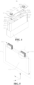
- Fig. 5 is a schematic structural diagram of a wound electrode assembly 23 provided by some embodiments of the application
- Fig. 6 is an enlarged view of I in Fig. 5
- Fig. 7 is an expanded schematic view of the electrode sheet 231 provided by some embodiments of the present application.
- the electrode assembly 23 is the wound electrode assembly 23, and the wound electrode assembly 23 includes an electrode sheet 231.
- the electrode sheet 231 includes a winding ending section 2313, the winding ending section 2313 is provided with a plurality of first tabs 2314, the plurality of first tabs 2314 are laminated, and among the two adjacent first tabs 2314, a width of the first tab 2314 close to a winding center of the wound electrode assembly 23 is greater than a width of the first tab 2314 away from the winding center.
- the wound electrode assembly 23 may include a positive electrode sheet, a negative electrode sheet and a separator.
- the wound electrode assembly 23 is a wound structure formed by winding the positive electrode sheet, the separator and the negative electrode sheet.
- the separator is used to separate the positive electrode sheet and the negative electrode sheet to reduce a risk of a short circuit due to contact between the positive electrode sheet and the negative electrode sheet.
- the number of turns of the winding ending section 2313 extending from a winding end in an opposite direction of a winding direction is m, and the total number of turns of the electrode sheet 231 is n, where m ⁇ n, m>2, that is, the number of turns of the winding ending section 2313 extending from the winding end in the opposite direction of the winding direction D exceeds two turns, and each turn of the winding ending section 2313 may be provided with at least one first tab 2314.
- the positive electrode sheet includes a positive electrode current collector and a positive electrode active material layer, a surface of the positive electrode current collector is coated with the positive electrode active material layer, the positive electrode current collector not coated with the positive electrode active material layer protrudes from the positive electrode current collector already coated with the positive electrode active material layer, and the positive electrode current collector not coated with the positive electrode active material layer is used as the positive electrode tab 2311.
- the material of the positive electrode current collector may be aluminum, and the positive active material may be lithium cobalt oxide, lithium iron phosphate, ternary lithium, lithium manganate, or the like.
- the negative electrode sheet includes a negative electrode current collector and a negative electrode active material layer, a surface of the negative electrode current collector is coated with the negative electrode active material layer, the negative electrode current collector not coated with the negative electrode active material layer protrudes from the negative electrode current collector already coated with the negative electrode active material layer, and the negative electrode current collector not coated with the negative electrode active material layer is used as the negative electrode tab 2312.
- the material of the negative electrode current collector may be copper, and the negative electrode active material may be carbon, silicon, or the like.
- a separator may be made from polypropylene (PP), polyethylene (PE), or the like.
- the positive electrode sheet has the positive electrode tab 2311, which can be the positive electrode current collector not coated with the positive electrode active material layer in the positive electrode sheet as the positive electrode tab 2311
- the negative electrode sheet has the negative electrode tab 2312, which can be the negative electrode current collector not coated with the negative electrode active material layer in the negative electrode sheet as the negative electrode tab 2312.
- the positive electrode tab 2311 and the negative electrode tab 2312 of the wound electrode assembly 23 may be located at one end of the electrode assembly in an axial direction B, or may be located at both ends of the electrode assembly in the axial direction B respectively.
- Fig. 5 shows a schematic structural diagram in which the positive electrode tab 2311 and the negative electrode tab 2312 are located at the same end of the electrode assembly in the axial direction B.
- the positive electrode tab 2311 of the positive electrode sheet and the negative electrode tab 2312 of the negative electrode sheet are arranged at intervals in a length direction A of the electrode assembly.
- the "electrode sheet 231" described in the present embodiment may be the positive electrode sheet or the negative electrode sheet.
- the first tab 2314 is the positive pole tab
- the first tab 2314 is the negative electrode tab.
- the plurality of first tabs 2314 are laminated means that the plurality of first tabs 2314 are sequentially arranged in a linear direction, and two adjacent first tabs 2314 at least partially overlap.
- the plurality of first tabs 2314 are laminated in a thickness direction C of the electrode assembly
- the plurality of first tabs 2314 are located on one side of a thickness center plane P of the electrode assembly 23
- the thickness center plane P of the electrode assembly 23 refers to a plane coplanar with a winding center axis of the electrode assembly 23 and perpendicular to the thickness direction C of the electrode assembly.
- the plurality of first tabs 2314 may be located on both sides of the thickness center plane P of the electrode assembly 23.
- the "width of the first tabs 2314" is a maximum size of the first tabs 2314 in a winding direction D
- misalignment of the first tabs 2314 refers to that projections of the two adjacent first tabs 2314 partially overlap in a stacking direction of the first tabs 2314
- the total amount of misalignment of the plurality of first tabs 2314 refers to a maximum width of the projections of the plurality of first tabs 2314 in the stacking direction of the first tabs 2314.
- the width of the first tabs 2314 refers to a maximum size of the first tabs 2314 in the length direction E (shown in Fig. 7 ) of the electrode sheet when the electrode sheet 231 is in an expanded state.
- the plurality of first tabs 2314 are laminated, and among the two adjacent first tabs 2314, the width of the first tab 2314 close to the winding center is greater than the width of the first tab 2314 away from the winding center.
- the widths of the plurality of first tabs 2314 gradually decrease, and after the winding ending section 2313 is wound, the amount of misalignment between the two adjacent first tabs 2314 is reduced in the width direction of the first tabs 2314, so that the total amount of misalignment shown by the plurality of first tabs 2314 is small, the risk of short circuit caused by the large amount of misalignment of the plurality of first tabs 2314 in the width direction of the first tabs 2314 of the electrode assembly 23 is reduced, and safety performance of the battery cell 20 is improved.
- the tabs of the electrode assembly 23 will be electrically connected with other components (such as the current collecting component 224 ) by welding and other modes, so as to draw out electric energy, but the area of a region of the current collecting component 224 for connection is limited, and a part of the tab of the electrode assembly 23 beyond the connection region of the current collecting component 224 will not be able to be connected with the current collecting component 224, which easily brings the risk of short circuit inside the battery cell 20.
- the total amount of misalignment shown by the plurality of first tabs 2314 is small, so the same connection region can correspond to more first tabs 2314, which is beneficial to increase the size of the electrode assembly in the thickness direction C, and can improve the energy density of the battery cell 20.
- the electrode sheet 231 further includes a winding start section 2315 connected with the winding ending section 2313, the winding start section 2315 is provided with a second tab 2316, and the second tab 2316 and the plurality of the first tabs 2314 are laminated.
- a width of the second tab 2316 is greater than or equal to a width of the first tab 2314 closest to the winding center among the plurality of first tabs 2314.
- the winding start section 2315 completes winding prior to the winding ending section 2313, and the second tab 2316 is arranged in the winding start section 2315, so the second tab 2316 is closer to the winding center of the electrode assembly 23 relative to the plurality of first tabs 2314.
- the winding start section 2315 extends at least one turn from a winding start end of the electrode sheet 231 in the winding direction D, and each turn of the winding start section 2315 may be provided with at least one second tab 2316.
- the quantity of the second tabs 2316 may be one or more.
- the second tabs 2316 and the plurality of first tabs 2314 are laminated means that the plurality of second tabs 2316 are laminated, and a direction in which the plurality of second tabs 2316 are laminated is the same as a direction in which the plurality of first tabs 2314 are laminated.
- first tabs 2314 and the second tabs 2316 belong to the same electrode sheet 231, polarity of the second tabs 2316 and polarity of the first tabs 2314 are the same.
- first tabs 2314 are the positive electrode tabs 2311
- the second tabs 2316 are the positive electrode tabs 2311
- the second tabs 2316 are the negative electrode tabs 2312.
- each second tab 2316 is greater than a width of the innermost first tab 2314 of the plurality of first tabs 2314. In some other embodiments, the width of each second tab 2316 is equal to a width of the innermost first tab 2314 of the plurality of second tabs 2316.
- the amount of misalignment of the second tab 2316 on the winding start section 2315 of the electrode assembly 23 is small in a width direction of the second tab 2316, therefore, the width of the second tab 2316 is greater than or equal to the width of the plurality of first tabs 2314, so that the tabs of the electrode assembly 23 may have a good current-carrying capacity and a good heat-dissipating capacity without affecting the total amount of misalignment of the electrode sheet 231.
- the quantity of the second tabs 2316 is multiple, the plurality of second tabs 2316 are laminated, and the widths of the plurality of second tabs 2316 are equal.
- the widths of the plurality of second tabs 2316 are equal, which not only facilitates manufacturing, but also enables the tabs to have the good current-carrying capacity and heat-dissipating capacity in a case of matching the connection region of the current collecting component 224.
- the quantity of the second tabs 2316 is less than or equal to 25.
- the quantity of the second tabs 2316 is less than or equal to 25, and only includes the second tabs 2316 on the same side as the plurality of first tabs 2314 and laminated with the plurality of first tabs 2314 in the same direction.
- the amount of misalignment of the tabs increases.
- the quantity of the second tabs 2316 is less than or equal to 25
- the total amount of misalignment of the first tabs 2314 of the electrode assembly 23 in the width direction of the first tabs 2314 cab be effectively reduced, and the risk of the short circuit caused by the large amount of misalignment of the plurality of first tabs 2314 in the width direction of the first tabs 2314 is reduced.
- the quantity of the second tabs 2316 is multiple, and the plurality of second tabs 2316 are laminated. Among the two adjacent second tabs 2316, the width of the second tab 2316 close to the winding center is greater than the width of the second tab 2316 away from the winding center.
- the plurality of second tabs 2316 are laminated in the same direction as the stacking direction of the plurality of first tabs 2314, and among the two adjacent second tabs 2316, the width of the second tabs 2316 close to the winding center is greater than the width of the second tabs 2316 away from the winding center. In other words, from the inside to the outside, the widths of the plurality of second tabs 2316 gradually decrease, so that the second tabs 2316 have the good current-carrying capacity and the good heat-dissipating capacity.
- the first tabs 2314 have connection ends 23141 and free ends 23142, and the connection ends 23141 are connected to one end of the winding ending section 2313 in the width direction F of the electrode sheet; and the width of each first tab 2314 of the plurality of first tabs 2314 gradually decreases in a direction from the connection ends 23141 to the free ends 23142.
- the width direction F of the electrode sheet is consistent with an axial direction B of the electrode assembly 23.
- the width direction F of the electrode sheet is perpendicular to the length direction E of the electrode sheet.
- the free ends 23142 of the first tabs 2314 refer to the end opposite to the connection ends 23141 and not connected with the winding ending section 2313. In the direction from the connection ends 23141 to the free ends 23142, there are many structures in which the width of each first tab 2314 in the plurality of first tabs 2314 gradually decreases.
- the first tabs 2314 are each an isosceles trapezoid or a right-angled trapezoid.
- each first tab 2314 In the direction from the connection ends 23141 to the free ends 23142 of the first tabs 2314, the width of each first tab 2314 gradually decreases to avoid interference with other components. In addition, on the basis of ensuring a welding area between the first tabs 2314 and other components, the connection strength between the first tabs 2314 and the winding ending section 2313 is increased.
- each first tab 2314 is equal in the direction from the connection ends to the free ends 23142 of the first tabs 2314. with continued reference to Fig. 7 , in some embodiments, a width difference between the two adjacent first tabs 2314 is equal.
- the width difference between the two adjacent first tabs 2314 is equal means that, taking one first tab 2314 as a reference, the width difference between the first tab 2314 and the first tab 2314 on its inner side is equal to the width difference between the first tab 2314 and the first tab 2314 on its outer side.
- the widths of the plurality of first tabs 2314 decrease linearly, which can reduce the total amount of misalignment of the plurality of first tabs 2314 in the width direction of the first tabs 2314, and reduce the risk of the short circuit caused by the large amount of misalignment of the plurality of first tabs 2314 in the width direction of the first tabs 2314.
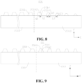
- Fig. 8 is a schematic expanded view of an electrode sheet 231 provided by some other embodiments of the present application.
- the width difference between the two adjacent first tabs 2314 gradually increases in the direction of the plurality of first tabs 2314 facing away from the winding center.
- the width difference between the two adjacent first tabs 2314 gradually increases means that, taking one first tab 2314 as a reference, the width difference between the first tab 2314 and the first tab 2314 on its inner side is less than the width difference between the first tab 2314 and the first tab 2314 on its outer side.
- the widths of the plurality of first tabs 2314 increase in a quadratic relationship, so that the width difference between the two adjacent first tabs 2314 gradually increases, which can reduce the total amount of misalignment of the plurality of first tabs 2314 in the width direction of the first tabs 2314, and reduce the risk of the short circuit caused by the large amount of misalignment of the plurality of first tabs 2314 in the width direction of the first tabs 2314.
- the width difference between the two adjacent first tabs 2314 is 0.5mm-4mm in the direction of the plurality of first tabs 2314 facing away from the winding center.
- the width difference between the two adjacent first tabs 2314 is 0.5mm-4mm, which can effectively reduce the risk of the short circuit caused by the large amount of misalignment of the plurality of first tabs 2314 in the width direction of the first tabs 2314, and can further ensure the current-carrying capacity and the heat-dissipating capacity of the first tabs 2314.
- the width difference between the two adjacent first tabs 2314 is less than 0.5mm, among the two adjacent first tabs 2314, the width of one first tab 2314 away from the winding center is not significantly decreased relative to the width of one first tab 2314 close to the winding center, and finally the total amount of misalignment of the plurality of first tabs 2314 is not significantly reduced, which cannot effectively reduce the risk of the short circuit caused by the large amount of misalignment of the plurality of first tabs 2314 in the width direction of the first tabs 2314.
- the width difference between the two adjacent first tabs 2314 is greater than 4 mm, among the two adjacent first tabs 2314, the width of one first tab 2314 away from the winding center is decreased too much relative to the width of one first tab 2314 close to the winding center, which makes it difficult to ensure the current-carrying capability and heat-dissipating capacity of the first tabs 2314.
- a height of the plurality of first tabs 2314 gradually decreases in the direction of the plurality of first tabs 2314 facing away from the winding center.
- the "height of the first tabs 2314" refers to a maximum size between the free ends 23142 of the first tabs 2314 and the connection ends 23141 of the first tabs 2314.
- the heights of the first tabs 2314 may be equal or may not be equal in the winding direction D.
- the height of the plurality of first tabs 2314 gradually decreases in the direction of the plurality of first tabs 2314 facing away from the winding center. That is, the width and height of the first tabs 2314 decrease synchronously, so that the risk of the first tabs 2314 are prone to being folded after the width decreases.
- a ratio of the width to the height of each first tab 2314 of the plurality of first tabs 2314 is the same.
- the ratio of the width to the height of each first tab 2314 of the plurality of first tabs 2314 is the same. in other words, after the width of the first tabs 2314 decreases, the height of the first tabs 2314 synchronously decreases, which reduces the risk that the first tabs 2314 are prone to being folded after the width decreases.
- the heights of the plurality of first tabs 2314 may be the same. In some other embodiments, the ratio of the width to the height of each first tab 2314 of the plurality of first tabs 2314 may not be equal. With continued reference to Fig. 8 , in some embodiments, a distance between the two adjacent first tabs 2314 gradually increases in a winding direction D of the wound electrode assembly 23.
- the distance between the two adjacent first tabs 2314 refers to a distance between a center position of the first tab 2314 and a center position of its adjacent first tab 2314 in the winding direction D of the wound electrode assembly 23.
- the "distance between the two adjacent first tabs 2314” refers to a distance between a center position of the two first tabs 2314 adjacent in the length direction E of the electrode sheet and a center position of its adjacent first tab 2314.
- the "distance between the two adjacent first tabs 2314 in the winding direction D of the wound electrode assembly 23" may adopt other reference definitions, but should adopt the same reference when defining the distance between any two adjacent first tabs 2314 in the winding direction D.
- Q1, Q2 and Q3 are respectively middle positions of the three first tabs 2314 in the length direction E of the electrode sheet, a distance between Q1 and Q2 is L1, and a distance between Q2 and Q3 is L2.
- the distance between the two adjacent first tabs 2314 gradually increases means that L2 is greater than L1.
- the winding direction D is consistent with the length direction E of the electrode sheet.
- the distance between the two adjacent first tabs 2314 gradually increases in the winding direction D of the wound electrode assembly 23, which can reduce the amount of misalignment of the two adjacent first tabs 2314, and thus reduce the risk of the short circuit caused by the large amount of misalignment of the plurality of first tabs 2314 in the width direction of the first tabs 2314.
- Fig. 9 is a schematic expanded view of the electrode sheet 231 provided by some another embodiments of the present application.
- the heights of each of the plurality of first tabs 2314 are the same.
- a projection of the first tab 2314 with the smaller width in the stacking direction of the first tab 2314 falls into a projection range of the first tab 2314 with the larger width in the stacking direction of the first tab 2314, and in the width direction of the first tab 2314, both ends of the first tab 2314 with the larger width exceed both ends of the first tab 2314 with the smaller width, and both ends of the first tab 2314 with the larger width exceed both ends of the first tab 2314 with the smaller width by the same value.
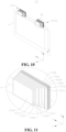
- Fig. 10 is a schematic structural diagram of an electrode assembly 23 provided by some other embodiments of the present application.
- Fig. 11 is an enlarged view of II in Fig. 10 .
- the projection of the first tab 2314 with the smaller width in the stacking direction of the first tab 2314 falls into the projection range of the first tab 2314 with the larger width in the stacking direction of the first tab 2314, and in the width direction of the first tab 2314, both ends of the first tab 2314 with the larger width exceed both ends of the first tab 2314 with the smaller width by the unequal value.
- the projection of the first tab 2314 with the smaller width in the stacking direction of the first tab 2314 falls into the projection range of the first tab 2314 with the larger width in the stacking direction of the first tab 2314, one end of the first tab 2314 with the larger width exceeds one end of the first tab 2314 with the smaller width, and the other end of the first tab 2314 with the larger width is flush with another end of the first tab 2314 with the smaller width.
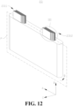
- Fig. 12 is a schematic structural diagram of an electrode assembly 23 provided by some further embodiments of the present application
- Fig. 13 is an enlarged view of II in Fig. 12 .
- the tabs of the electrode sheet 231 are partially overlapped. That is, the projection of the first tab 2314 with the smaller width in the stacking direction of the first tab 2314 partially falls into the projection range of the first tab 2314 with the larger width in the stacking direction of the first tab 2314, and in the width direction of the first tab 2314, one end of the first tab 2314 with the larger width exceeds one end of the first tab 2314 with the smaller width, and another end of the first tab 2314 with the smaller width exceeds another end of the first tab 2314 with the larger width.
- an embodiment of the present application provides a square battery 100.
- An electrode assembly 23 is arranged in a case 21, the electrode assembly 23 includes two electrode sheets 231, one of the two electrode sheets 231 is a positive electrode sheet, and the other is a negative electrode sheet.
- Each electrode sheet 231 includes a connected winding ending section 2313 and winding ending section 2313, the winding ending section 2313 is provided with a plurality of first tabs 2314, the winding start section 2315 is provided with a plurality of second tabs 2316, the first tabs 2314 are laminated, the plurality of second tabs 2316 are laminated, and a stacking direction of the plurality of first tabs 2314 is the same as a stacking direction of the plurality of second tabs 2316.
- a width of one first tab 2314 close to a winding center is greater than a width of one first tab 2314 away from the winding center
- a width of each second tab 2316 is greater than the width of the innermost first tab 2314
- the widths of the plurality of second tabs 2316 are equal.
- the width of the tabs of the electrode sheet 231 begins to decrease, even if the amount of misalignment of the outer ring layer is large, the total amount of misalignment shown by the tabs of the electrode sheet 231 will become smaller, thereby reducing a risk of short circuit caused by misalignment, which is further beneficial to increase the thickness design of the square shell battery 100 and improve the energy density.
- the plurality of first tabs 2314 and the plurality of second tabs 2316 are located on the same side of a thickness center plane P, and the first tabs 2314 and the second tabs 2316 of each electrode sheet 231 are located at one end of the electrode assembly in an axial direction B.
- the tabs of the two electrode sheets 231 are located at the same end of the electrode assembly in the axial direction B.
- An embodiment of the present application further provides a battery cell 20.
- the battery cell 20 includes a case 21 and the wound electrode assembly 23 provided by any above embodiment.
- An embodiment of the present application further provides a battery 100.
- the battery 100 includes a box body 10 and the battery 100 provided by the above embodiments.
- the battery 100 is accommodated in the box body 10.
- An embodiment of the present application further provides an electrical device.
- the electrical device includes the battery cell 20 provided by the above embodiments.
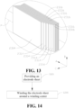
- FIG. 14 is a flow chart of a method for manufacturing a wound electrode assembly 23 provided by some embodiments of the present application.
- An embodiment of the present application further provides a method for manufacturing a wound electrode assembly 23, including:
- the electrode sheet 231 is wound around the winding center, so that the plurality of the first tabs 2314 are laminated.
- the total amount of misalignment shown by the plurality of first tabs 2314 is small, which reduces a risk of a short circuit caused by the large amount of misalignment of the plurality of first tabs 2314 in a width direction of the first tabs 2314, can also improve safety performance of a battery cell 20, and improves electrical safety of an electrical device.
- the total amount of misalignment shown by the plurality of first tabs 2314 is small, therefore the same region can correspond to more first tabs 2314, which is beneficial to increase a size of the electrode assembly in a thickness direction C, and improves energy density of the battery cell 20.
- FIG. 15 is a structural sketch of a manufacturing apparatus 2000 for a wound electrode assembly provided by some embodiments of the present application.
- An embodiment of the present application further provides a manufacturing apparatus 2000 for a wound electrode assembly, including a providing means 2100 and an assembling means 2200.
- the providing means 2100 is configured to provide an electrode sheet 231, wherein the electrode sheet 231 includes a winding ending section 2313, and the winding ending section 2313 is provided with a plurality of first tabs 2314.
- the assembling means 2200 is configured to wind the electrode sheet 231 around a winding center, so that the plurality of the first tabs 2314 are laminated, wherein, among the two adjacent first tabs 2314, a width of the first tab 2314 close to the winding center of the wound electrode assembly 23 is greater than a width of the first tab 2314 away from the winding center.
- the assembling means 2200 winds the electrode sheet 231 around the winding center, so that the plurality of the first tabs 2314 are laminated.
- the total amount of misalignment of the plurality of first tabs 2314 is small, which reduces a risk of a short circuit caused by the large amount of misalignment of the plurality of first tabs 2314 in a width direction of the first tabs 2314, can also improve safety performance of a battery cell 20, and improves electrical safety of an electrical device.
- the total amount of misalignment shown by the plurality of first tabs 2314 is small, therefore the same region can correspond to more first tabs 2314, which is beneficial to increase a size of the electrode assembly in a thickness direction C, and improves energy density of the battery cell 20.
Landscapes
- Chemical & Material Sciences (AREA)
- Chemical Kinetics & Catalysis (AREA)
- Electrochemistry (AREA)
- General Chemical & Material Sciences (AREA)
- Engineering & Computer Science (AREA)
- Manufacturing & Machinery (AREA)
- Aviation & Aerospace Engineering (AREA)
- Life Sciences & Earth Sciences (AREA)
- Biophysics (AREA)
- Computer Hardware Design (AREA)
- Connection Of Batteries Or Terminals (AREA)
- Secondary Cells (AREA)
Abstract
Description
- The present application relates to the technical field of batteries, in particular to a wound electrode assembly, a battery cell, a battery, an electrical device, and a method and manufacturing apparatus for the wound electrode assembly.
- At present, lithium-ion batteries are widely used in a vehicle, a portable appliance, a mobile phone, a spacecraft and other fields to provide electric energy for them.
- Many design factors, such as energy density, a cycle life, a discharge capacity, a charge-discharge rate and other performance parameters, should be considered in development of a battery technology. In addition, the safety of the battery further needs to be considered, and a short circuit inside the battery is one of the important factors affecting safety performance of the battery. Therefore, how to reduce a risk of the short circuit inside the battery becomes an urgent problem to be solved.
- Embodiments of the present application provide a wound electrode assembly, a battery cell, a battery, an electrical device, and a method and manufacturing apparatus for the wound electrode assembly.
- In a first aspect, an embodiment of the present application provides a wound electrode assembly, including: an electrode sheet. The electrode sheet includes a winding ending section, the winding ending section is provided with a plurality of first tabs, the plurality of first tabs are laminated, and among the two adjacent first tabs, a width of the first tab close to a winding center of the wound electrode assembly is greater than a width of the first tab away from the winding center.
- In the above technical solution, the plurality of first tabs are laminated, and among the two adjacent first tabs, the width of the first tab close to the winding center is greater than the width of the first tab away from the winding center. In other words, from inside to outside, the widths of the plurality of first tabs gradually decrease, and after the winding ending section is wound, the amount of misalignment between the two adjacent first tabs is reduced in a width direction of the first tabs, so that the total amount of misalignment shown by the plurality of first tabs is small, the risk of short circuit caused by the large amount of misalignment of the plurality of first tabs in the width direction of the first tabs of the electrode assembly is reduced, and safety performance of a battery cell is improved. The total amount of misalignment shown by the plurality of first tabs is small, therefore the same connection region can correspond to more first tabs, which is beneficial to increase a size of the electrode assembly in a thickness direction, and can improve the energy density of the battery cell.
- In some embodiments of the first aspect of the present application, the electrode sheet further includes a winding start section connected with the winding ending section, the winding start section is provided with a second tab, and the second tab and the plurality of the first tabs are laminated. A width of the second tab is greater than or equal to a width of the first tab closest to the winding center among the plurality of first tabs.
- In the above technical solution, in an actual winding process, the amount of misalignment of the second tab on the winding start section of the electrode assembly is small in a width direction of the second tab, therefore, the width of the second tab is greater than or equal to the width of the plurality of first tabs, so that the tabs of the electrode assembly may have a good current-carrying capacity and a good heat-dissipating capacity without affecting the total amount of misalignment of the tabs of the electrode assembly.
- In some embodiments of the first aspect of the present application, the quantity of the second tabs is multiple, the plurality of second tabs are laminated, and the widths of the plurality of second tabs are equal.
- In the above technical solution, the widths of the plurality of second tabs are equal, which not only facilitates manufacturing, but also enables the tabs to have the good current-carrying capacity and heat-dissipating capacity.
- In some embodiments of the first aspect of the present application, the quantity of the second tabs is less than or equal to 25.
- In the above technical solution, as a winding radius of the electrode sheet increases, the amount of misalignment of the tabs increases. Therefore, the quantity of the second tabs is less than or equal to 25, which can effectively reduce the total amount of misalignment of the first tabs and the second tabs in the width direction of the first tabs, and reduce the risk of the short circuit caused by the large amount of misalignment of the plurality of first tabs in the width direction of the first tabs.
- In some embodiments of the first aspect of the present application, the quantity of the second tabs is multiple, and the plurality of second tabs are laminated. Among the two adjacent second tabs, the width of the second tab close to the winding center is greater than the width of the second tab away from the winding center.
- In the above technical solution, the plurality of second tabs are laminated in the same direction as the stacking direction of the plurality of first tabs, and among the two adjacent second tabs, the width of the second tabs close to the winding center is greater than the width of the second tabs away from the winding center. In other words, from the inside to the outside, the widths of the plurality of second tabs gradually decrease, so that the second tabs have the good current-carrying capacity and the good heat-dissipating capacity.
- In some embodiments of the first aspect of the present application, the first tabs have connection ends and free ends, and the connection ends are connected to one end of the winding ending section in the width direction of the electrode sheet; and the width of each first tab of the plurality of first tabs gradually decreases in a direction from the connection ends to the free ends.
- In the above technical solution, in the direction from the connection ends to the free ends of the first tabs, the width of each first tab gradually decreases to avoid interference with other components. In addition, on the basis of ensuring a welding area between the first tabs and other components, the connection strength between the first tabs and the winding ending section is increased.
- In some embodiments of the first aspect of the present application, a width difference between the two adjacent first tabs is equal.
- In the above technical solution, the width difference between the two adjacent first tabs is equal. That is, in the direction of the first tabs facing away from the winding center, the widths of the plurality of first tabs decrease linearly, which can reduce the total amount of misalignment of the plurality of first tabs in the width direction of the first tabs, and reduce the risk of the short circuit caused by the large amount of misalignment of the plurality of first tabs in the width direction of the first tabs.
- In some embodiments of the first aspect of the present application, in the stacking direction of the plurality of first tabs, the width difference between the two adjacent first tabs gradually increases in the direction of the plurality of first tabs facing away from the winding center.
- In the above technical solution, the width difference between the two adjacent first tabs gradually increases, which can reduce the total amount of misalignment generated by the plurality of first tabs in the width direction of the first tabs, and reduce the risk of the short circuit of the electrode assembly caused by the large amount of misalignment of the plurality of first tabs in the width direction of the first tabs.
- In some embodiments of the first aspect of the present application, in the stacking direction of the plurality of first tabs, the width difference between the two adjacent first tabs is 0.5mm-4mm in the direction of the plurality of first tabs facing away from the winding center.
- In the above technical solution, the width difference between the two adjacent first tabs is 0.5mm-4mm, which can effectively reduce the risk of the short circuit caused by the large amount of misalignment of the plurality of first tabs in the width direction of the first tabs, and can further ensure the current-carrying capacity and the heat-dissipating capacity of the first tabs. In the case where the width difference between the two adjacent first tabs is less than 0.5mm, among the two adjacent first tabs, the width of one first tab away from the winding center is not significantly decreased relative to the width of one first tab close to the winding center, and finally the total amount of misalignment of the plurality of first tabs is not significantly reduced, which cannot effectively reduce the risk of the short circuit caused by the large amount of misalignment of the plurality of first tabs in the width direction of the first tabs. In the case where the width difference between the two adjacent first tabs is greater than 4 mm, among the two adjacent first tabs, the width of one first tab away from the winding center is decreased too much relative to the width of one first tab close to the winding center, which makes it difficult to ensure the current-carrying capability and heat-dissipating capacity of the first tabs.
- In some embodiments of the present application, in the stacking direction of the plurality of first tabs, the height of the plurality of first tabs gradually decreases in the direction of the plurality of first tabs facing away from the winding center.
- In some embodiments of the present application, the height of the plurality of first tabs gradually decreases in the direction of the plurality of first tabs facing away from the winding center. That is, the width and height of the first tabs decrease synchronously, so that the risk of the first tabs are prone to being folded after the width decreases.
- In some embodiments of the first aspect of the present application, a ratio of the width to the height of each first tab of the plurality of first tabs is the same.
- In some embodiments of the present application, the ratio of the width to the height of each first tab of the plurality of first tabs is the same. After the width of the first tabs decreases, the height of the first tabs synchronously decreases, which reduces the risk that the first tabs are prone to being folded after the width decreases.
- In some embodiments of the first aspect of the present application, a distance between the two adjacent first tabs gradually increases in a winding direction of the wound electrode assembly.
- In the above technical solution, the distance between the two adjacent first tabs gradually increases in the winding direction of the wound electrode assembly, which can reduce the amount of misalignment of the two adjacent first tabs, and thus reduce the risk of the short circuit caused by the large amount of misalignment of the plurality of first tabs in the width direction of the first tabs.
- In a second aspect, an embodiment of the present application provides a battery cell, including a case and the wound electrode assembly provided by the embodiment of the first aspect, wherein the wound electrode assembly is accommodated in the case.
- In the above technical solution, from inside to outside, widths of a plurality of first tabs of a winding ending section gradually decrease, and after the winding ending section is wound, the amount of misalignment between the two adjacent first tabs is reduced in a width direction of the first tabs, so that the total amount of misalignment shown by the plurality of first tabs is small, and a risk of a short circuit caused by the large amount of misalignment of the plurality of first tabs in the width direction of the first tabs is reduced. The total amount of misalignment shown by the plurality of first tabs is small, therefore the same connection region can correspond to more first tabs, which is beneficial to increase a size of the electrode assembly in a thickness direction, and improves energy density of the battery cell.
- In a third aspect, an embodiment of the present application provides a battery, including a box body and the battery cell provided by the embodiment of the second aspect, wherein the battery cell is accommodated in the box body.
- In the above technical solution, from inside to outside, widths of a plurality of first tabs of a winding ending section gradually decrease, and after the winding ending section is wound, the amount of misalignment between the two adjacent first tabs is reduced in a width direction of the first tabs, so that the total amount of misalignment shown by the plurality of first tabs is small, a risk of a short circuit caused by the large amount of misalignment of the plurality of first tabs in the width direction of the first tabs is reduced, and safety performance of the battery can also be improved. The total amount of misalignment shown by the plurality of first tabs is small, therefore the same connection region can correspond to more first tabs, which is beneficial to increase a size of the electrode assembly in a thickness direction, and improves energy density of the battery.
- In a fourth aspect, an embodiment of the present application provides an electrical device, including the battery cell provided by the embodiment in the second aspect.
- In the above technical solution, the total amount of misalignment shown by a plurality of first tabs is small, which reduces a risk of a short circuit caused by the large amount of misalignment of the plurality of first tabs in a width direction of the first tabs, can also improve safety performance of the battery cell, and improves electrical safety of the electrical device. The total amount of misalignment shown by the plurality of first tabs is small, therefore the same region can correspond to more first tabs, which is beneficial to increase a size of an electrode assembly in a thickness direction, and improves energy density of the battery cell, so as to meet the larger and longer-term electric energy demands of the electrical device.
- In a fifth aspect, an embodiment of the present application provides a method for manufacturing a wound electrode assembly, including:
- providing an electrode sheet, wherein the electrode sheet includes a winding ending section, and the winding ending section is provided with a plurality of first tabs; and
- winding the electrode sheet around a winding center, so that the plurality of the first tabs are laminated.
- Wherein, among the two adjacent first tabs, a width of the first tab close to the winding center of the wound electrode assembly is greater than a width of the first tab away from the winding center.
- In the above technical solution, the electrode sheet is wound around the winding center, so that the plurality of the first tabs are laminated. The total amount of misalignment shown by the plurality of first tabs is small, which reduces a risk of a short circuit caused by the large amount of misalignment of the plurality of first tabs in a width direction of the first tabs, can also improve safety performance of a battery cell, and improves electrical safety of an electrical device. The total amount of misalignment shown by the plurality of first tabs is small, therefore the same region can correspond to more first tabs, which is beneficial to increase a size of the electrode assembly in a thickness direction, and improves energy density of the battery cell.
- In a sixth aspect, an embodiment of the present application provides a manufacturing apparatus for a wound electrode assembly, including a providing means and an assembling means. The providing means is configured to provide an electrode sheet, wherein the electrode sheet includes a winding ending section, and the winding ending section is provided with a plurality of first tabs. The assembling means is configured to wind the electrode sheet around a winding center, so that the plurality of the first tabs are laminated. Wherein, among the two adjacent first tabs, a width of the first tab close to the winding center of the wound electrode assembly is greater than a width of the first tab away from the winding center.
- In the above technical solution, the assembling means winds the electrode sheet around the winding center, so that the plurality of the first tabs are laminated. The total amount of misalignment shown by the plurality of first tabs is small, which reduces a risk of a short circuit caused by the large amount of misalignment of the plurality of first tabs in a width direction of the first tabs, can also improve safety performance of a battery cell, and improves electrical safety of an electrical device. The total amount of misalignment shown by the plurality of first tabs is small, therefore the same region can correspond to more first tabs, which is beneficial to increase a size of the electrode assembly in a thickness direction, and improves energy density of the battery cell.
- To more clearly describe the technical solutions in embodiments of the present application, the drawings to be used in the embodiments will be briefly introduced below. It should be understood that the following drawings only show some embodiments of the present application, and therefore, they should not be regarded as a limitation to the scope. For those of ordinary skills in the art, other related drawings may also be obtained based on these drawings without making creative work.
-
Fig. 1 is a schematic structural diagram of a vehicle provided by some embodiments of the present application; -
Fig. 2 is a schematic structural diagram of a battery provided by some embodiments of the present application; -
Fig. 3 is a schematic structural diagram of a plurality of battery cells connected by a bus component provided by some embodiments of the present application; -
Fig. 4 is an exploded view of a battery cell provided by some embodiments of the present application; -
Fig. 5 is a schematic structural diagram of a wound electrode assembly provided by some embodiments of the present application; -
Fig. 6 is an enlarged view of I inFig. 5 . -
Fig. 7 is a schematic expanded view of an electrode sheet provided by some embodiments of the present application; -
Fig. 8 is a schematic expanded view of an electrode sheet provided by some other embodiments of the present application. -
Fig. 9 is a schematic expanded view of an electrode sheet provided by some another embodiments of the present application. -
Fig. 10 is a schematic structural diagram of an electrode assembly provided by some other embodiments of the present application. -
Fig. 11 is an enlarged view of II inFig. 10 . -
Fig. 12 is a schematic structural diagram of an electrode assembly provided by some another embodiments of the present application. -
Fig. 13 is an enlarged view of II inFig. 12 . -
Fig. 14 is a flow chart of a method for manufacturing a wound electrode assembly provided by some embodiments of the present application; -
Fig. 15 is a structural sketch of a manufacturing apparatus for a wound electrode assembly provided by some embodiments of the present application. - Icon: 1000-vehicle; 100-battery; 10-box body; 11-accommodating space; 12-first part; 13-second part; 20-battery cell; 21-case; 21 1-opening; 22-end cap assembly; 221-end cap; 222-first electrode terminal; 223-second electrode terminal; 224-current collecting component; 224a-first current collecting component; 224b-second current collecting part; 225-pressure relief mechanism; 23-electrode assembly; 231-electrode sheet; 2311-positive electrode tab; 2312-negative electrode tab; 23 13 -winding ending section; 23 14- first tab; 23141-connection end; 23142-free end; 2315-winding start section; 2316-second tab; 30-bus component; 200-controller; 300-motor; 2000-manufacturing apparatus for wound electrode assembly; 2100-providing means; 2200-assembling means; A-length direction of electrode assembly; B-axis direction of electrode assembly; C-thickness direction of electrode assembly; D-winding direction; E-length direction of electrode sheet; F-width direction of electrode sheet; P- thickness center plane.
- For the objects, technical solutions and advantages of the embodiments of the present application to be clearer, the technical solutions in the embodiments of the present application will be clearly and completely described below in conjunction with the drawings in the embodiments of the present application, and it is apparent that the described embodiments are a part of the embodiments of the present application rather than all the embodiments. The assembly of the embodiments of the present application generally described and illustrated in the drawings herein can be arranged and designed in a variety of different configurations.
- Accordingly, the following detailed description of the embodiments of the present application provided in the drawings is not intended to limit the scope of the claimed application, rather it is only representative of selected embodiments of the present application. Based on the embodiments in the present application, all other embodiments obtained by those of ordinary skill in the art without creative effort fall within the protection scope of the present application.
- It should be noted that in case of no conflicts, the embodiments in the present application and the features in the embodiments can be combined with each other.
- It should be noted that like numerals and letters refer to like items in the following drawings, so once an item is defined in one drawing, it does not require further definition and explanation in subsequent drawings.
- In the description of the embodiments of the present application, it should be noted that the indicated orientation or positional relationship is the orientation or positional relationship shown based on the drawings, or the orientation or positional relationship that is usually placed when the application product is used, or the orientation or positional relationship that is commonly understood by those skilled in the art, and is only for It is only for the convenience of describing the present application and for simplifying the description, but do not indicate or imply that the apparatuses or elements referred to must have particular orientations, be constructed and operated in particular orientations, and therefore cannot be construed as a limitation of the present application. In addition, the terms "first", "second" and "third" are only used to differentiate the description, and cannot be construed as indicating or implying relative importance.
- A wound electrode assembly is formed by stacking and winding a positive electrode sheet, a separator and a negative electrode sheet. Positive electrode tabs of the positive electrode sheet are laminated, and each positive electrode tab is required to be completely overlapped or the amount of misalignment should be controlled within a certain range. Negative electrode tabs of the negative electrode sheet are laminated, and each negative electrode tab is required to be completely overlapped or the amount of misalignment should be controlled within a certain range. However, in the process of winding the electrode assembly, a winding radius of the electrode sheet becomes larger and larger, resulting in a larger total amount of misalignment shown by the positive electrode tabs and/or the negative electrode tabs.
- However, the large total amount of misalignment of the tabs will lead to many problems. For example, the large total amount of misalignment of the tabs leads to decrease of a distance between the positive electrode tabs and the negative electrode tabs, increase of a risk of a short circuit, and influence on safety of a battery cell. For another example, the large total amount of misalignment of the tabs leads to a small overlap area between the tabs, which reduces a welding area with other components (such as an electrode terminal, an end cap, and a current collecting component), thereby reducing a current-carrying area, and affecting the safety of battery cell.
- Based on this, in order to improve the problem of misalignment of the tabs, the inventor designed an electrode assembly after in-depth research. A plurality of first tabs at a winding ending section of an electrode sheet are laminated, and among the two adjacent first tabs, a width of the first tab close to a winding center of the wound electrode assembly is greater than a width of the first tab away from the winding center. In other words, from inside to outside, the widths of the plurality of first tabs gradually decrease, the amount of misalignment between the two adjacent first tabs is reduced, so that the total amount of misalignment shown by the plurality of first tabs is small, and the risk of the short circuit is reduced. The total amount of misalignment shown by the plurality of first tabs is small, therefore the same connection region can correspond to more first tabs, which is beneficial to increase a size of the electrode assembly in a thickness direction, and can improve the energy density of the battery cell.
- The technical solutions described in the embodiments of the present application are applicable to a battery and an electrical device using the battery.
- The electrical device may be a vehicle, a mobile phone, a portable device, a laptop, a ship, a spacecraft, an electric toy, an electric tool, and the like. The vehicle may be a fuel vehicle, a gas vehicle or a new energy vehicle. The new energy vehicle may be an all-electric vehicle, a hybrid vehicle, an range extended electric vehicle, or the like. The spacecraft includes airplanes, rockets, space shuttles, spaceships, and the like. The electric toy includes fixed or mobile electric toys, such as game consoles, electric car toys, electric ship toys and electric aircraft toys. The electric tool includes metal cutting electric tools, grinding electric tools, assembly electric tools and railway electric tools, such as electric drills, electric grinders, electric wrenches, electric screwdrivers, electric hammers, impact drills, concrete vibrators and electric planers. The embodiments of the present application do not impose special limitations on the above electrical device.
- In the following embodiments, for convenience of description, the electrical device being a vehicle is taken as an example for description.
- Please refer to
Fig. 1 , which is a schematic structural diagram of avehicle 1000 provided by some embodiments of the present application. Thevehicle 1000 may be a fuel vehicle, a gas vehicle, or a new energy vehicle, and the new energy vehicle may be an all-electric vehicle, a hybrid vehicle, an range extended electric vehicle, or the like. - The interior of the
vehicle 1000 is provided with abattery 100, which can be arranged at the bottom or head or tail of thevehicle 1000. Thebattery 100 may be used to supply power to thevehicle 1000, for example, thebattery 100 may serve as an operating power source for thevehicle 1000. -
Vehicle 1000 may further includecontroller 200 andmotor 300, whereincontroller 200 is configured to controlbattery 100 topower motor 300, for example, for the operating power demand whenvehicle 1000 is starting, navigating, and driving. - In some embodiments of the present application, the
battery 100 not only may serve as the operating power source of thevehicle 1000, but also may serve as a driving power source of thevehicle 1000, thus replacing or partially replacing fuel or natural gas to provide driving power for thevehicle 1000. - Please refer to
Fig. 2 , which is a schematic structural diagram of thebattery 100 provided by some embodiments of the present application. Thebattery 100 includes abox body 10 and abattery cell 20, and thebattery cell 20 is accommodated in thebox body 10. - The
box body 10 is used to provide an accommodating space 11 for thebattery cell 20. In some embodiments, thebox body 10 may include a first part 12 and asecond part 13, and the first part 12 and thesecond part 13 are covered with each other to define the accommodating space 11 for accommodating thebattery cell 20. Of course, connection between the first part 12 and thesecond part 13 may be sealed by a sealing member (not shown in the figure), and the sealing member may be a sealing ring, a sealant or the like. - The first part 12 and the
second part 13 may be in various shapes, such as a cuboid and a cylinder. The first part 12 may be of a hollow structure with one side open, and thesecond part 13 may also be of a hollow structure with one side open. The open side of thesecond part 13 covers the open side of the first part 12 to form thebox body 10 having the accommodating space 11. Of course, the first part 12 may also be of a hollow structure with one side open, and thesecond part 13 may be of a plate-like structure. Thesecond part 13 covers the open side of the first part 12 to form thebox body 10 with the accommodating space 11. - In the
battery 100, there may be one ormore battery cells 20. If there are the plurality ofbattery cells 20, the plurality ofbattery cells 20 may be connected in series or in parallel or in a mixed connection. The mixed connection means that the plurality ofbattery cells 20 are connected in both series and parallel. The plurality ofbattery cells 20 may be directly connected in series or parallel or in mixed connection together, and then the whole constituted by the plurality ofbattery cells 20 is accommodated in thebox body 10. Of course, the plurality ofbattery cells 20 may also be first connected in series or parallel or in mixed connection to form a battery module, and the plurality of battery modules are connected in series or parallel or in mixed connection to form a whole which is accommodated in thebox body 10. Thebattery cells 20 may be in the shape of a cylinder, a flat body, a cuboid or others.Fig. 2 exemplarily shows a case where thebattery cells 20 are square. - Please refer to
Fig. 3 , which is a schematic structural diagram of the plurality ofbattery cells 20 connected by abus component 30 provided by some embodiments of the present application. In some embodiments, thebattery 100 may further include thebus component 30, and the plurality ofbattery cells 20 may be electrically connected through thebus component 30, so as to realize parallel connection, series connection or mixed connection of the plurality ofbattery cells 20. - Please refer to
Fig. 4 , which is an exploded view of thebattery cell 20 provided by some embodiments of the present application. Thebattery cell 20 may include acase 21, anend cap assembly 22 and anelectrode assembly 23. Thecase 21 has anopening 211, theelectrode assembly 23 is accommodated in thecase 21, and theend cap assembly 22 is used to cover theopening 211. - The
case 21 may be in various shapes, such as a cylinder and a cuboid. The shape of thecase 21 may be determined according to the specific shape of theelectrode assembly 23. For example, if theelectrode assembly 23 is of a cylindrical structure, thecase 21 may be selected as a cylindrical structure; and if theelectrode assembly 23 is of a cuboid structure, thecase 21 may be selected as a cuboid structure.Fig. 5 exemplarily shows a case where thecase 21 and theelectrode assembly 23 are square. - A material of the
case 21 may be various, such as copper, iron, aluminum, stainless steel and aluminum alloy, which is not particularly limited in the embodiments of the present application. - The
end cap assembly 22 is used to cover theopening 211 of thecase 21 to form a closed accommodating cavity (not shown in the figure), and the accommodating cavity is used to accommodate theelectrode assembly 23. The accommodating cavity is further used to accommodate an electrolyte, such as an electrolyte solution. Theend cap assembly 22 is used as a component for outputting electric energy of theelectrode assembly 23, and an electrode terminal in theend cap assembly 22 is used for being electrically connected with theelectrode assembly 23, that is, the electrode terminal is electrically connected with tabs of theelectrode assembly 23. In some embodiments, the electrode terminal and the tabs are connected through acurrent collecting component 224 to realize the electrical connection between the electrode terminal and the tabs. - It should be noted that the
case 21 may have one or twoopenings 211. If thecase 21 has oneopening 211, theend cap assembly 22 may also be one, and the two electrode terminals may be arranged in theend cap assembly 22. The two electrode terminals are respectively used for being electrically connected with apositive electrode tab 2311 and anegative electrode tab 2312 of theelectrode assembly 23, and the two electrode terminals in theend cap assembly 22 are a positive electrode terminal and a negative electrode terminal respectively. If thecase 21 has the twoopenings 211, for example, the twoopenings 211 are formed in two opposite sides of thecase 21, there may also be twoend cap assemblies 22, and the twoend cap assemblies 22 respectively cover the twoopenings 211 of thecase 21. In this case, the electrode terminal in oneend cap assembly 22 may be a positive electrode terminal for being electrically connected with thepositive electrode tab 2311 of theelectrode assembly 23; and the electrode terminal in the otherend cap assembly 22 may be a negative electrode terminal for being electrically connected with thenegative electrode tab 2312 of theelectrode assembly 23. - As shown in
Fig. 4 , thebattery cell 20 has oneend cap assembly 22. Anend cap 221 is provided with afirst electrode terminal 222 for being electrically connected with thepositive electrode tab 2311 and asecond electrode terminal 223 for being electrically connected with thenegative electrode tab 2312. Thebattery cell 20 further includes a first current collecting component 224a and a secondcurrent collecting component 224b, thepositive electrode tab 2311 and thefirst electrode terminal 222 are electrically connected through the first current collecting component 224a, and thenegative electrode tab 2312 and thesecond electrode terminal 223 are electrically connected through the secondcurrent collecting component 224b. - The
end cap assembly 22 is further provided with apressure relief mechanism 225 for actuating to relieve pressure inside thebattery cell 20 when the temperature or pressure inside thebattery cell 20 reaches a threshold value. Thepressure relief mechanism 225 may take the form of an explosion-proof valve, an explosion-proof sheet, a gas valve, a pressure relief valve or a safety valve, etc., and may specifically adopt a pressure-sensitive or temperature-sensitive element or structure. That is, when the internal pressure or temperature of thebattery cell 20 reaches a predetermined threshold value, thepressure relief mechanism 225 executes an action or a weak structure provided in thepressure relief mechanism 225 is damaged, so as to form an opening or channel for releasing the internal pressure or temperature. - As shown in
Figs. 5 ,6 and7 ,Fig. 5 is a schematic structural diagram of awound electrode assembly 23 provided by some embodiments of the application,Fig. 6 is an enlarged view of I inFig. 5 , andFig. 7 is an expanded schematic view of theelectrode sheet 231 provided by some embodiments of the present application. In some embodiments, theelectrode assembly 23 is thewound electrode assembly 23, and thewound electrode assembly 23 includes anelectrode sheet 231. Theelectrode sheet 231 includes a windingending section 2313, the windingending section 2313 is provided with a plurality offirst tabs 2314, the plurality offirst tabs 2314 are laminated, and among the two adjacentfirst tabs 2314, a width of thefirst tab 2314 close to a winding center of thewound electrode assembly 23 is greater than a width of thefirst tab 2314 away from the winding center. - The
wound electrode assembly 23 may include a positive electrode sheet, a negative electrode sheet and a separator. Thewound electrode assembly 23 is a wound structure formed by winding the positive electrode sheet, the separator and the negative electrode sheet. The separator is used to separate the positive electrode sheet and the negative electrode sheet to reduce a risk of a short circuit due to contact between the positive electrode sheet and the negative electrode sheet. - The number of turns of the winding
ending section 2313 extending from a winding end in an opposite direction of a winding direction is m, and the total number of turns of theelectrode sheet 231 is n, where m<n, m>2, that is, the number of turns of the windingending section 2313 extending from the winding end in the opposite direction of the winding direction D exceeds two turns, and each turn of the windingending section 2313 may be provided with at least onefirst tab 2314. - The positive electrode sheet includes a positive electrode current collector and a positive electrode active material layer, a surface of the positive electrode current collector is coated with the positive electrode active material layer, the positive electrode current collector not coated with the positive electrode active material layer protrudes from the positive electrode current collector already coated with the positive electrode active material layer, and the positive electrode current collector not coated with the positive electrode active material layer is used as the
positive electrode tab 2311. Taking a lithium-ion battery as an example, the material of the positive electrode current collector may be aluminum, and the positive active material may be lithium cobalt oxide, lithium iron phosphate, ternary lithium, lithium manganate, or the like. The negative electrode sheet includes a negative electrode current collector and a negative electrode active material layer, a surface of the negative electrode current collector is coated with the negative electrode active material layer, the negative electrode current collector not coated with the negative electrode active material layer protrudes from the negative electrode current collector already coated with the negative electrode active material layer, and the negative electrode current collector not coated with the negative electrode active material layer is used as thenegative electrode tab 2312. The material of the negative electrode current collector may be copper, and the negative electrode active material may be carbon, silicon, or the like. In order to ensure that no fusing occurs when a large current passes, there are the plurality ofpositive electrode tabs 2311 which are laminated together, and there are the plurality ofnegative electrode tabs 2312 which are laminated together. A separator may be made from polypropylene (PP), polyethylene (PE), or the like. - The positive electrode sheet has the
positive electrode tab 2311, which can be the positive electrode current collector not coated with the positive electrode active material layer in the positive electrode sheet as thepositive electrode tab 2311, and the negative electrode sheet has thenegative electrode tab 2312, which can be the negative electrode current collector not coated with the negative electrode active material layer in the negative electrode sheet as thenegative electrode tab 2312. Thepositive electrode tab 2311 and thenegative electrode tab 2312 of thewound electrode assembly 23 may be located at one end of the electrode assembly in an axial direction B, or may be located at both ends of the electrode assembly in the axial direction B respectively.Fig. 5 shows a schematic structural diagram in which thepositive electrode tab 2311 and thenegative electrode tab 2312 are located at the same end of the electrode assembly in the axial direction B. InFig. 5 , thepositive electrode tab 2311 of the positive electrode sheet and thenegative electrode tab 2312 of the negative electrode sheet are arranged at intervals in a length direction A of the electrode assembly. - Therefore, the "
electrode sheet 231" described in the present embodiment may be the positive electrode sheet or the negative electrode sheet. When the "electrode sheet 231" is the positive electrode sheet, thefirst tab 2314 is the positive pole tab, and when the "electrode sheet 231" is the negative electrode sheet, thefirst tab 2314 is the negative electrode tab. - "The plurality of
first tabs 2314 are laminated" means that the plurality offirst tabs 2314 are sequentially arranged in a linear direction, and two adjacentfirst tabs 2314 at least partially overlap. In some embodiments, the plurality offirst tabs 2314 are laminated in a thickness direction C of the electrode assembly, the plurality offirst tabs 2314 are located on one side of a thickness center plane P of theelectrode assembly 23, and the thickness center plane P of theelectrode assembly 23 refers to a plane coplanar with a winding center axis of theelectrode assembly 23 and perpendicular to the thickness direction C of the electrode assembly. In some other embodiments, the plurality offirst tabs 2314 may be located on both sides of the thickness center plane P of theelectrode assembly 23. - When the
electrode sheet 231 is in a winding state, the "width of thefirst tabs 2314" is a maximum size of thefirst tabs 2314 in a winding direction D, and misalignment of thefirst tabs 2314 refers to that projections of the two adjacentfirst tabs 2314 partially overlap in a stacking direction of thefirst tabs 2314, and the total amount of misalignment of the plurality offirst tabs 2314 refers to a maximum width of the projections of the plurality offirst tabs 2314 in the stacking direction of thefirst tabs 2314. "The width of thefirst tabs 2314" refers to a maximum size of thefirst tabs 2314 in the length direction E (shown inFig. 7 ) of the electrode sheet when theelectrode sheet 231 is in an expanded state. - The plurality of
first tabs 2314 are laminated, and among the two adjacentfirst tabs 2314, the width of thefirst tab 2314 close to the winding center is greater than the width of thefirst tab 2314 away from the winding center. In other words, from inside to outside, the widths of the plurality offirst tabs 2314 gradually decrease, and after the windingending section 2313 is wound, the amount of misalignment between the two adjacentfirst tabs 2314 is reduced in the width direction of thefirst tabs 2314, so that the total amount of misalignment shown by the plurality offirst tabs 2314 is small, the risk of short circuit caused by the large amount of misalignment of the plurality offirst tabs 2314 in the width direction of thefirst tabs 2314 of theelectrode assembly 23 is reduced, and safety performance of thebattery cell 20 is improved. - Generally, the tabs of the
electrode assembly 23 will be electrically connected with other components (such as the current collecting component 224 ) by welding and other modes, so as to draw out electric energy, but the area of a region of thecurrent collecting component 224 for connection is limited, and a part of the tab of theelectrode assembly 23 beyond the connection region of thecurrent collecting component 224 will not be able to be connected with thecurrent collecting component 224, which easily brings the risk of short circuit inside thebattery cell 20. The total amount of misalignment shown by the plurality offirst tabs 2314 is small, so the same connection region can correspond to morefirst tabs 2314, which is beneficial to increase the size of the electrode assembly in the thickness direction C, and can improve the energy density of thebattery cell 20. - It should be noted that "from the inside to the outside" refers to a direction in the winding center of the
electrode assembly 23 facing toward thefirst tabs 2314 with respect to thefirst tabs 2314 relative to the winding center of theelectrode assembly 23. "Inside" refers to the winding center of theelectrode assembly 23, and "outside" refers to the outer side of theelectrode assembly 23. - With continued reference to
Fig. 7 , in some embodiments, theelectrode sheet 231 further includes a windingstart section 2315 connected with the windingending section 2313, the windingstart section 2315 is provided with asecond tab 2316, and thesecond tab 2316 and the plurality of thefirst tabs 2314 are laminated. A width of thesecond tab 2316 is greater than or equal to a width of thefirst tab 2314 closest to the winding center among the plurality offirst tabs 2314. - In the winding process, the winding
start section 2315 completes winding prior to the windingending section 2313, and thesecond tab 2316 is arranged in the windingstart section 2315, so thesecond tab 2316 is closer to the winding center of theelectrode assembly 23 relative to the plurality offirst tabs 2314. - The winding
start section 2315 extends at least one turn from a winding start end of theelectrode sheet 231 in the winding direction D, and each turn of the windingstart section 2315 may be provided with at least onesecond tab 2316. - The quantity of the
second tabs 2316 may be one or more. In an embodiment in which the quantity of thesecond tabs 2316 is multiple, "thesecond tabs 2316 and the plurality offirst tabs 2314 are laminated" means that the plurality ofsecond tabs 2316 are laminated, and a direction in which the plurality ofsecond tabs 2316 are laminated is the same as a direction in which the plurality offirst tabs 2314 are laminated. - If the
first tabs 2314 and thesecond tabs 2316 belong to thesame electrode sheet 231, polarity of thesecond tabs 2316 and polarity of thefirst tabs 2314 are the same. In an embodiment in which thefirst tabs 2314 are thepositive electrode tabs 2311, thesecond tabs 2316 are thepositive electrode tabs 2311, and in an embodiment in which thefirst tabs 2314 are thenegative electrode tabs 2312, thesecond tabs 2316 are thenegative electrode tabs 2312. - In some embodiments, the width of each
second tab 2316 is greater than a width of the innermostfirst tab 2314 of the plurality offirst tabs 2314. In some other embodiments, the width of eachsecond tab 2316 is equal to a width of the innermostfirst tab 2314 of the plurality ofsecond tabs 2316. - In an actual winding process, the amount of misalignment of the
second tab 2316 on the windingstart section 2315 of theelectrode assembly 23 is small in a width direction of thesecond tab 2316, therefore, the width of thesecond tab 2316 is greater than or equal to the width of the plurality offirst tabs 2314, so that the tabs of theelectrode assembly 23 may have a good current-carrying capacity and a good heat-dissipating capacity without affecting the total amount of misalignment of theelectrode sheet 231. - In some embodiments, the quantity of the
second tabs 2316 is multiple, the plurality ofsecond tabs 2316 are laminated, and the widths of the plurality ofsecond tabs 2316 are equal. - The widths of the plurality of
second tabs 2316 are equal, which not only facilitates manufacturing, but also enables the tabs to have the good current-carrying capacity and heat-dissipating capacity in a case of matching the connection region of thecurrent collecting component 224. - In some embodiments, the quantity of the
second tabs 2316 is less than or equal to 25. - The quantity of the
second tabs 2316 is less than or equal to 25, and only includes thesecond tabs 2316 on the same side as the plurality offirst tabs 2314 and laminated with the plurality offirst tabs 2314 in the same direction. - As a winding radius of the
electrode sheet 231 increases, the amount of misalignment of the tabs increases. In a case that the quantity of thesecond tabs 2316 is less than or equal to 25, the total amount of misalignment of thefirst tabs 2314 of theelectrode assembly 23 in the width direction of thefirst tabs 2314 cab be effectively reduced, and the risk of the short circuit caused by the large amount of misalignment of the plurality offirst tabs 2314 in the width direction of thefirst tabs 2314 is reduced. - In some embodiments, the quantity of the
second tabs 2316 is multiple, and the plurality ofsecond tabs 2316 are laminated. Among the two adjacentsecond tabs 2316, the width of thesecond tab 2316 close to the winding center is greater than the width of thesecond tab 2316 away from the winding center. - The plurality of
second tabs 2316 are laminated in the same direction as the stacking direction of the plurality offirst tabs 2314, and among the two adjacentsecond tabs 2316, the width of thesecond tabs 2316 close to the winding center is greater than the width of thesecond tabs 2316 away from the winding center. In other words, from the inside to the outside, the widths of the plurality ofsecond tabs 2316 gradually decrease, so that thesecond tabs 2316 have the good current-carrying capacity and the good heat-dissipating capacity. - With continued reference to
Fig. 7 , in some embodiments, thefirst tabs 2314 have connection ends 23141 andfree ends 23142, and the connection ends 23141 are connected to one end of the windingending section 2313 in the width direction F of the electrode sheet; and the width of eachfirst tab 2314 of the plurality offirst tabs 2314 gradually decreases in a direction from the connection ends 23141 to the free ends 23142. - When the
electrode sheet 231 is wound to form theelectrode assembly 23, the width direction F of the electrode sheet is consistent with an axial direction B of theelectrode assembly 23. When theelectrode sheet 231 is in the expanded state, the width direction F of the electrode sheet is perpendicular to the length direction E of the electrode sheet. - The free ends 23142 of the
first tabs 2314 refer to the end opposite to the connection ends 23141 and not connected with the windingending section 2313. In the direction from the connection ends 23141 to the free ends 23142, there are many structures in which the width of eachfirst tab 2314 in the plurality offirst tabs 2314 gradually decreases. For example, thefirst tabs 2314 are each an isosceles trapezoid or a right-angled trapezoid. - In the direction from the connection ends 23141 to the free ends 23142 of the
first tabs 2314, the width of eachfirst tab 2314 gradually decreases to avoid interference with other components. In addition, on the basis of ensuring a welding area between thefirst tabs 2314 and other components, the connection strength between thefirst tabs 2314 and the windingending section 2313 is increased. - In some other embodiments, the width of each
first tab 2314 is equal in the direction from the connection ends to the free ends 23142 of thefirst tabs 2314.
with continued reference toFig. 7 , in some embodiments, a width difference between the two adjacentfirst tabs 2314 is equal. - "The width difference between the two adjacent
first tabs 2314 is equal" means that, taking onefirst tab 2314 as a reference, the width difference between thefirst tab 2314 and thefirst tab 2314 on its inner side is equal to the width difference between thefirst tab 2314 and thefirst tab 2314 on its outer side. - In the direction of the
first tabs 2314 facing away from the winding center, the widths of the plurality offirst tabs 2314 decrease linearly, which can reduce the total amount of misalignment of the plurality offirst tabs 2314 in the width direction of thefirst tabs 2314, and reduce the risk of the short circuit caused by the large amount of misalignment of the plurality offirst tabs 2314 in the width direction of thefirst tabs 2314. - Please refer to
Fig. 8 , which is a schematic expanded view of anelectrode sheet 231 provided by some other embodiments of the present application. In some embodiments, in the stacking direction of the plurality offirst tabs 2314, the width difference between the two adjacentfirst tabs 2314 gradually increases in the direction of the plurality offirst tabs 2314 facing away from the winding center. - "The width difference between the two adjacent
first tabs 2314 gradually increases" means that, taking onefirst tab 2314 as a reference, the width difference between thefirst tab 2314 and thefirst tab 2314 on its inner side is less than the width difference between thefirst tab 2314 and thefirst tab 2314 on its outer side. In some embodiments, in the direction of thefirst tabs 2314 facing away from the winding center, the widths of the plurality offirst tabs 2314 increase in a quadratic relationship, so that the width difference between the two adjacentfirst tabs 2314 gradually increases, which can reduce the total amount of misalignment of the plurality offirst tabs 2314 in the width direction of thefirst tabs 2314, and reduce the risk of the short circuit caused by the large amount of misalignment of the plurality offirst tabs 2314 in the width direction of thefirst tabs 2314. - In some embodiments, in the stacking direction of the plurality of
first tabs 2314, the width difference between the two adjacentfirst tabs 2314 is 0.5mm-4mm in the direction of the plurality offirst tabs 2314 facing away from the winding center. The width difference between the two adjacentfirst tabs 2314 is 0.5mm-4mm, which can effectively reduce the risk of the short circuit caused by the large amount of misalignment of the plurality offirst tabs 2314 in the width direction of thefirst tabs 2314, and can further ensure the current-carrying capacity and the heat-dissipating capacity of thefirst tabs 2314. In the case where the width difference between the two adjacentfirst tabs 2314 is less than 0.5mm, among the two adjacentfirst tabs 2314, the width of onefirst tab 2314 away from the winding center is not significantly decreased relative to the width of onefirst tab 2314 close to the winding center, and finally the total amount of misalignment of the plurality offirst tabs 2314 is not significantly reduced, which cannot effectively reduce the risk of the short circuit caused by the large amount of misalignment of the plurality offirst tabs 2314 in the width direction of thefirst tabs 2314. In the case where the width difference between the two adjacentfirst tabs 2314 is greater than 4 mm, among the two adjacentfirst tabs 2314, the width of onefirst tab 2314 away from the winding center is decreased too much relative to the width of onefirst tab 2314 close to the winding center, which makes it difficult to ensure the current-carrying capability and heat-dissipating capacity of thefirst tabs 2314.
with continued reference toFig. 8 , in some embodiments, in the stacking direction of the plurality offirst tabs 2314, a height of the plurality offirst tabs 2314 gradually decreases in the direction of the plurality offirst tabs 2314 facing away from the winding center. - The "height of the
first tabs 2314" refers to a maximum size between the free ends 23142 of thefirst tabs 2314 and the connection ends 23141 of thefirst tabs 2314. The heights of thefirst tabs 2314 may be equal or may not be equal in the winding direction D. - The height of the plurality of
first tabs 2314 gradually decreases in the direction of the plurality offirst tabs 2314 facing away from the winding center. That is, the width and height of thefirst tabs 2314 decrease synchronously, so that the risk of thefirst tabs 2314 are prone to being folded after the width decreases. - In some embodiments, a ratio of the width to the height of each
first tab 2314 of the plurality offirst tabs 2314 is the same. - The ratio of the width to the height of each
first tab 2314 of the plurality offirst tabs 2314 is the same. in other words, after the width of thefirst tabs 2314 decreases, the height of thefirst tabs 2314 synchronously decreases, which reduces the risk that thefirst tabs 2314 are prone to being folded after the width decreases. - Of course, in some embodiments, the heights of the plurality of
first tabs 2314 may be the same. In some other embodiments, the ratio of the width to the height of eachfirst tab 2314 of the plurality offirst tabs 2314 may not be equal.
with continued reference toFig. 8 , in some embodiments, a distance between the two adjacentfirst tabs 2314 gradually increases in a winding direction D of thewound electrode assembly 23. - "In the winding direction D of the
wound electrode assembly 23, the distance between the two adjacentfirst tabs 2314" refers to a distance between a center position of thefirst tab 2314 and a center position of its adjacentfirst tab 2314 in the winding direction D of thewound electrode assembly 23. In other words, when theelectrode sheet 231 is in the expanded state, the "distance between the two adjacentfirst tabs 2314" refers to a distance between a center position of the twofirst tabs 2314 adjacent in the length direction E of the electrode sheet and a center position of its adjacentfirst tab 2314. Of course, in other embodiments, the "distance between the two adjacentfirst tabs 2314 in the winding direction D of thewound electrode assembly 23" may adopt other reference definitions, but should adopt the same reference when defining the distance between any two adjacentfirst tabs 2314 in the winding direction D. As shown inFig. 8 , in the figure, Q1, Q2 and Q3 are respectively middle positions of the threefirst tabs 2314 in the length direction E of the electrode sheet, a distance between Q1 and Q2 is L1, and a distance between Q2 and Q3 is L2. "The distance between the two adjacentfirst tabs 2314 gradually increases" means that L2 is greater than L1. - It should be noted that, after the
electrode sheet 231 is wound, the winding direction D is consistent with the length direction E of the electrode sheet. - During the winding process, the more turns of winding, the greater the total amount of misalignment shown by the tabs, especially the greater the total amount of misalignment of the tabs of an outer ring layer. Therefore, the distance between the two adjacent
first tabs 2314 gradually increases in the winding direction D of thewound electrode assembly 23, which can reduce the amount of misalignment of the two adjacentfirst tabs 2314, and thus reduce the risk of the short circuit caused by the large amount of misalignment of the plurality offirst tabs 2314 in the width direction of thefirst tabs 2314. - Please refer to
Fig. 9 , which is a schematic expanded view of theelectrode sheet 231 provided by some another embodiments of the present application. In some embodiments, the heights of each of the plurality offirst tabs 2314 are the same. - In some embodiments, after winding, a projection of the
first tab 2314 with the smaller width in the stacking direction of thefirst tab 2314 falls into a projection range of thefirst tab 2314 with the larger width in the stacking direction of thefirst tab 2314, and in the width direction of thefirst tab 2314, both ends of thefirst tab 2314 with the larger width exceed both ends of thefirst tab 2314 with the smaller width, and both ends of thefirst tab 2314 with the larger width exceed both ends of thefirst tab 2314 with the smaller width by the same value. - Please refer to
Fig. 10 , which is a schematic structural diagram of anelectrode assembly 23 provided by some other embodiments of the present application.Fig. 11 is an enlarged view of II inFig. 10 . In some embodiments, after winding, the projection of thefirst tab 2314 with the smaller width in the stacking direction of thefirst tab 2314 falls into the projection range of thefirst tab 2314 with the larger width in the stacking direction of thefirst tab 2314, and in the width direction of thefirst tab 2314, both ends of thefirst tab 2314 with the larger width exceed both ends of thefirst tab 2314 with the smaller width by the unequal value. In some other embodiments, in the width direction of thefirst tabs 2314, the projection of thefirst tab 2314 with the smaller width in the stacking direction of thefirst tab 2314 falls into the projection range of thefirst tab 2314 with the larger width in the stacking direction of thefirst tab 2314, one end of thefirst tab 2314 with the larger width exceeds one end of thefirst tab 2314 with the smaller width, and the other end of thefirst tab 2314 with the larger width is flush with another end of thefirst tab 2314 with the smaller width. - Please refer to
Fig. 12 , which is a schematic structural diagram of anelectrode assembly 23 provided by some further embodiments of the present application, andFig. 13 is an enlarged view of II inFig. 12 . After winding, the tabs of theelectrode sheet 231 are partially overlapped. That is, the projection of thefirst tab 2314 with the smaller width in the stacking direction of thefirst tab 2314 partially falls into the projection range of thefirst tab 2314 with the larger width in the stacking direction of thefirst tab 2314, and in the width direction of thefirst tab 2314, one end of thefirst tab 2314 with the larger width exceeds one end of thefirst tab 2314 with the smaller width, and another end of thefirst tab 2314 with the smaller width exceeds another end of thefirst tab 2314 with the larger width. - In some embodiments, referring to
Fig. 4 and Fig. 5 , an embodiment of the present application provides asquare battery 100. Anelectrode assembly 23 is arranged in acase 21, theelectrode assembly 23 includes twoelectrode sheets 231, one of the twoelectrode sheets 231 is a positive electrode sheet, and the other is a negative electrode sheet. Eachelectrode sheet 231 includes a connected windingending section 2313 and windingending section 2313, the windingending section 2313 is provided with a plurality offirst tabs 2314, the windingstart section 2315 is provided with a plurality ofsecond tabs 2316, thefirst tabs 2314 are laminated, the plurality ofsecond tabs 2316 are laminated, and a stacking direction of the plurality offirst tabs 2314 is the same as a stacking direction of the plurality ofsecond tabs 2316. Among the two adjacentfirst tabs 2314, a width of onefirst tab 2314 close to a winding center is greater than a width of onefirst tab 2314 away from the winding center, a width of eachsecond tab 2316 is greater than the width of the innermostfirst tab 2314, and the widths of the plurality ofsecond tabs 2316 are equal. It is equivalent to that starting from a certain turn, the width of the tabs of theelectrode sheet 231 begins to decrease, even if the amount of misalignment of the outer ring layer is large, the total amount of misalignment shown by the tabs of theelectrode sheet 231 will become smaller, thereby reducing a risk of short circuit caused by misalignment, which is further beneficial to increase the thickness design of thesquare shell battery 100 and improve the energy density. - The plurality of
first tabs 2314 and the plurality ofsecond tabs 2316 are located on the same side of a thickness center plane P, and thefirst tabs 2314 and thesecond tabs 2316 of eachelectrode sheet 231 are located at one end of the electrode assembly in an axial direction B. The tabs of the twoelectrode sheets 231 are located at the same end of the electrode assembly in the axial direction B. - An embodiment of the present application further provides a
battery cell 20. Thebattery cell 20 includes acase 21 and thewound electrode assembly 23 provided by any above embodiment. - An embodiment of the present application further provides a
battery 100. Thebattery 100 includes abox body 10 and thebattery 100 provided by the above embodiments. Thebattery 100 is accommodated in thebox body 10. - An embodiment of the present application further provides an electrical device. The electrical device includes the
battery cell 20 provided by the above embodiments. - Please refer to
Fig. 14 , which is a flow chart of a method for manufacturing awound electrode assembly 23 provided by some embodiments of the present application. An embodiment of the present application further provides a method for manufacturing awound electrode assembly 23, including: - step S100, providing an
electrode sheet 231, wherein theelectrode sheet 231 includes a windingending section 2313, and the windingending section 2313 is provided with a plurality offirst tabs 2314; and - step S200, winding the
electrode sheet 231 around a winding center, so that the plurality of thefirst tabs 2314 are laminated, - wherein, among the two adjacent
first tabs 2314, a width of thefirst tab 2314 close to the winding center of thewound electrode assembly 23 is greater than a width of thefirst tab 2314 away from the winding center. - The
electrode sheet 231 is wound around the winding center, so that the plurality of thefirst tabs 2314 are laminated. The total amount of misalignment shown by the plurality offirst tabs 2314 is small, which reduces a risk of a short circuit caused by the large amount of misalignment of the plurality offirst tabs 2314 in a width direction of thefirst tabs 2314, can also improve safety performance of abattery cell 20, and improves electrical safety of an electrical device. The total amount of misalignment shown by the plurality offirst tabs 2314 is small, therefore the same region can correspond to morefirst tabs 2314, which is beneficial to increase a size of the electrode assembly in a thickness direction C, and improves energy density of thebattery cell 20. - Please refer to
Fig. 15 , which is a structural sketch of amanufacturing apparatus 2000 for a wound electrode assembly provided by some embodiments of the present application. An embodiment of the present application further provides amanufacturing apparatus 2000 for a wound electrode assembly, including a providingmeans 2100 and an assembling means 2200. The providing means 2100 is configured to provide anelectrode sheet 231, wherein theelectrode sheet 231 includes a windingending section 2313, and the windingending section 2313 is provided with a plurality offirst tabs 2314. The assembling means 2200 is configured to wind theelectrode sheet 231 around a winding center, so that the plurality of thefirst tabs 2314 are laminated, wherein, among the two adjacentfirst tabs 2314, a width of thefirst tab 2314 close to the winding center of thewound electrode assembly 23 is greater than a width of thefirst tab 2314 away from the winding center. - The assembling means 2200 winds the
electrode sheet 231 around the winding center, so that the plurality of thefirst tabs 2314 are laminated. The total amount of misalignment of the plurality offirst tabs 2314 is small, which reduces a risk of a short circuit caused by the large amount of misalignment of the plurality offirst tabs 2314 in a width direction of thefirst tabs 2314, can also improve safety performance of abattery cell 20, and improves electrical safety of an electrical device. The total amount of misalignment shown by the plurality offirst tabs 2314 is small, therefore the same region can correspond to morefirst tabs 2314, which is beneficial to increase a size of the electrode assembly in a thickness direction C, and improves energy density of thebattery cell 20. - The above are only preferred embodiments of the present application, and are not intended to limit the present application. For those skilled in the art, the present application may have various modifications and changes. Any modifications, equivalent replacements, improvements, and the like made within the spirit and principle of the present application shall be included within the protection scope of the present application.
Claims (17)
- A wound electrode assembly, comprising:
an electrode sheet, comprising a winding ending section, wherein the winding ending section is provided with a plurality of first tabs, the plurality of first tabs are laminated, and among the two adjacent first tabs, a width of the first tab close to a winding center of the wound electrode assembly is greater than a width of the first tab away from the winding center. - The wound electrode assembly according to claim 1, wherein the electrode sheet further comprises a winding start section connected with the winding ending section, the winding start section is provided with a second tab, the second tab and the plurality of the first tabs are laminated; and
a width of the second tab is greater than or equal to the width of the first tab closest to the winding center among the plurality of first tabs. - The wound electrode assembly according to claim 2, wherein the quantity of the second tabs is multiple, the plurality of second tabs are laminated, and the widths of the plurality of second tabs are equal.
- The wound electrode assembly according to claim 3, wherein the quantity of the second tabs is less than or equal to 25.
- The wound electrode assembly according to claim 2, wherein the quantity of the second tabs is multiple, and among the two adjacent second tabs, the width of the second tab close to the winding center is greater than the width of the second tab away from the winding center.
- The wound electrode assembly according to any one of claims 1-5, wherein the first tabs have connection ends and free ends, and the connection ends are connected to one end of the winding ending section in a width direction of the electrode sheet; and
in a direction from the connection ends to the free ends, the width of each first tab of the plurality of first tabs gradually decreases. - The wound electrode assembly according to any one of claims 1-6, wherein a width difference between the two adjacent first tabs is equal.
- The wound electrode assembly according to any one of claims 1-6, wherein in a stacking direction of the plurality of first tabs, a width difference between the two adjacent first tabs gradually increases in a direction of the plurality of first tabs facing away from the winding center.
- The wound electrode assembly according to any one of claims 1-8, wherein in the stacking direction of the plurality of first tabs, the width difference between the two adjacent first tabs is 0.5mm-4mm in the direction of the plurality of first tabs facing away from the winding center.
- The wound electrode assembly according to any one of claims 1-9, wherein in the stacking direction of the plurality of first tabs, a height of the plurality of first tabs gradually decreases in the direction of the plurality of first tabs facing away from the winding center.
- The wound electrode assembly according to claim 10, a ratio of the width to the height of each first tab of the plurality of first tabs is the same.
- The wound electrode assembly according to any one of claims 1-11, wherein a distance between the two adjacent first tabs gradually increases in a winding direction of the wound electrode assembly.
- A battery cell, comprising:a case; andthe wound electrode assembly according to claim 12, wherein the wound electrode assembly is accommodated in the case.
- A battery, comprising:a box body; andthe battery cell according to claim 13, wherein the battery cell is accommodated in the box body.
- An electrical device, comprising the battery cell according to claim 13.
- A method for manufacturing a wound electrode assembly, comprising:providing an electrode sheet, wherein the electrode sheet includes a winding ending section, and the winding ending section is provided with a plurality of first tabs; andwinding the electrode sheet, so that the plurality of the first tabs are laminated;wherein, among the two adjacent first tabs, a width of the first tab close to the winding center of the wound electrode assembly is greater than a width of the first tab away from the winding center.
- A manufacturing apparatus for a wound electrode assembly, comprising:a providing means, configured to provide an electrode sheet, wherein the electrode sheet comprises a winding ending section, and the winding ending section is provided with a plurality of first tabs; andan assembling means, configured to wind the electrode sheet around a winding center, so that the plurality of the first tabs are laminated;wherein, among the two adjacent first tabs, a width of the first tab close to the winding center of the wound electrode assembly is greater than a width of the first tab away from the winding center.
Applications Claiming Priority (1)
| Application Number | Priority Date | Filing Date | Title |
|---|---|---|---|
| PCT/CN2021/115572 WO2023028815A1 (en) | 2021-08-31 | 2021-08-31 | Wound electrode assembly, battery cell, battery and electrical device |
Publications (2)
| Publication Number | Publication Date |
|---|---|
| EP4195399A1 true EP4195399A1 (en) | 2023-06-14 |
| EP4195399A4 EP4195399A4 (en) | 2024-10-16 |
Family
ID=85410676
Family Applications (1)
| Application Number | Title | Priority Date | Filing Date |
|---|---|---|---|
| EP21955296.5A Pending EP4195399A4 (en) | 2021-08-31 | 2021-08-31 | Wound electrode assembly, battery cell, battery and electrical device |
Country Status (6)
| Country | Link |
|---|---|
| US (1) | US20230216077A1 (en) |
| EP (1) | EP4195399A4 (en) |
| JP (1) | JP7577837B2 (en) |
| KR (1) | KR102942283B1 (en) |
| CN (1) | CN116686157A (en) |
| WO (1) | WO2023028815A1 (en) |
Families Citing this family (7)
| Publication number | Priority date | Publication date | Assignee | Title |
|---|---|---|---|---|
| CN110061182B (en) * | 2019-05-21 | 2020-12-01 | 宁德新能源科技有限公司 | Battery pole pieces and cells |
| CN115458873B (en) * | 2022-11-11 | 2023-09-26 | 深圳海辰储能控制技术有限公司 | Energy storage device, electric equipment and winding method |
| CN116387766B (en) * | 2023-06-05 | 2023-08-25 | 中创新航科技集团股份有限公司 | Cylindrical battery and battery pack |
| CN117913376B (en) * | 2024-01-16 | 2024-06-11 | 广州融捷能源科技有限公司 | Core structure and battery |
| CN119812500A (en) * | 2024-06-28 | 2025-04-11 | 比亚迪股份有限公司 | Battery cell components, battery cells, batteries and electrical devices |
| WO2026026017A1 (en) * | 2024-07-31 | 2026-02-05 | 湖北亿纬动力有限公司 | Electrode assembly, battery, battery pack and design method for electrode assembly |
| CN118888869B (en) * | 2024-09-27 | 2025-02-14 | 宁德时代新能源科技股份有限公司 | Battery cell, battery device and electricity utilization device |
Family Cites Families (16)
| Publication number | Priority date | Publication date | Assignee | Title |
|---|---|---|---|---|
| JP2011081964A (en) * | 2009-10-05 | 2011-04-21 | Toshiba Corp | Manufacturing device of electrode, manufacturing method of electrode, electrode, and nonaqueous electrolyte battery |
| KR20130013823A (en) * | 2011-07-29 | 2013-02-06 | 주식회사 엠플러스 | Secondary battery manufacturing method and secondary batter thereby |
| WO2014027606A1 (en) * | 2012-08-14 | 2014-02-20 | 株式会社 豊田自動織機 | Electrical storage device |
| JP6415959B2 (en) * | 2014-12-11 | 2018-10-31 | 株式会社東芝 | Electrode group, battery, and battery manufacturing method |
| KR102368089B1 (en) * | 2015-01-28 | 2022-02-24 | 삼성에스디아이 주식회사 | Electrode assembly and rechargeable battery having electrode tap |
| CN106257710A (en) * | 2015-06-17 | 2016-12-28 | 深圳市沃特玛电池有限公司 | A kind of multi pole ears becomes the high multiplying power lithium ion battery of size |
| KR102459618B1 (en) * | 2015-09-23 | 2022-10-27 | 삼성에스디아이 주식회사 | secondary battery |
| KR102384021B1 (en) * | 2015-09-24 | 2022-04-07 | 삼성에스디아이 주식회사 | Electrode assembly and secondary battery having the same |
| CN207097936U (en) * | 2017-07-06 | 2018-03-13 | 深圳市海目星激光科技有限公司 | One kind winding electrical chip, winding battery core and battery |
| CN108520936A (en) * | 2018-03-16 | 2018-09-11 | 深圳市沃特玛电池有限公司 | An aluminum shell cylindrical battery |
| US11322807B2 (en) * | 2018-07-20 | 2022-05-03 | Ruipu Energy Co., Ltd. | Electrode plate and battery cell of wound lithium-ion battery and method for manufacturing same |
| CN110061182B (en) * | 2019-05-21 | 2020-12-01 | 宁德新能源科技有限公司 | Battery pole pieces and cells |
| CN212136591U (en) * | 2020-05-25 | 2020-12-11 | 安徽泰能新能源科技有限公司 | Lithium ion battery positive pole piece and lithium ion battery |
| JP7396481B2 (en) * | 2020-06-09 | 2023-12-12 | 株式会社村田製作所 | Secondary batteries, electronic equipment and power tools |
| CN112103455A (en) * | 2020-08-28 | 2020-12-18 | 中天储能科技有限公司 | Tab structure, application of tab structure, preparation method and preparation device |
| WO2023004823A1 (en) * | 2021-07-30 | 2023-02-02 | 宁德时代新能源科技股份有限公司 | Wound-type electrode assembly, battery cell, battery and electric device |
-
2021
- 2021-08-31 CN CN202180082913.0A patent/CN116686157A/en active Pending
- 2021-08-31 JP JP2023515864A patent/JP7577837B2/en active Active
- 2021-08-31 WO PCT/CN2021/115572 patent/WO2023028815A1/en not_active Ceased
- 2021-08-31 EP EP21955296.5A patent/EP4195399A4/en active Pending
- 2021-08-31 KR KR1020237008779A patent/KR102942283B1/en active Active
-
2023
- 2023-03-10 US US18/181,597 patent/US20230216077A1/en active Pending
Also Published As
| Publication number | Publication date |
|---|---|
| US20230216077A1 (en) | 2023-07-06 |
| JP2023543681A (en) | 2023-10-18 |
| JP7577837B2 (en) | 2024-11-05 |
| EP4195399A4 (en) | 2024-10-16 |
| WO2023028815A1 (en) | 2023-03-09 |
| KR102942283B1 (en) | 2026-03-19 |
| KR20230051257A (en) | 2023-04-17 |
| CN116686157A (en) | 2023-09-01 |
Similar Documents
| Publication | Publication Date | Title |
|---|---|---|
| US20230123940A1 (en) | Battery cell, battery and power consuming device | |
| US20230216077A1 (en) | Spirally wound electrode assembly, battery cell, battery and electric apparatus | |
| EP4068418B1 (en) | Electrode assembly and manufacturing method therefor, battery cell, and battery | |
| EP4293769A1 (en) | Battery cell, battery, and electric device | |
| US11710872B2 (en) | Battery cell, battery, power consumption device and manufacturing device and method for battery cell | |
| CN215988963U (en) | Battery cell, battery and power consumption device | |
| CN216903136U (en) | Battery cells, batteries and electrical equipment | |
| US20240283059A1 (en) | Battery cell, method and system for manufacturing battery cell, battery, and electrical device | |
| US20240055646A1 (en) | Wound electrode assembly, battery cell, battery, and electrical device | |
| US20230216154A1 (en) | Current collecting member, battery cell, battery, and power consuming device | |
| EP4113732A1 (en) | Cylindrical battery cell, battery, and power consuming device | |
| EP4462582A1 (en) | Battery cell, battery, electric device, and battery cell manufacturing device and method | |
| US20240429504A1 (en) | Battery cell and manufacturing method therefor and battery | |
| CN217485645U (en) | End cap assemblies, battery cells, batteries and powered devices | |
| EP4738557A1 (en) | Battery cell, battery and electric device | |
| EP4318766A1 (en) | Insulating patch, battery cell, battery and device | |
| US20240055705A1 (en) | Battery cell, battery, power consuming apparatus, and method and apparatus for manufacturing battery cell | |
| US20230223642A1 (en) | Pressure relief apparatus, battery cell, battery, and electrical device | |
| US20230198089A1 (en) | Pressure relief apparatus, battery cell, battery and electric apparatus | |
| US12224456B2 (en) | Connection component, battery cell, battery and electrical device | |
| US12388143B2 (en) | Battery cell, battery, power consumption device and manufacturing device and method for battery cell | |
| CN221466747U (en) | Battery module, battery and power utilization device | |
| US20250070394A1 (en) | Electrode assembly, battery cell, battery, and electrical device | |
| US20260031503A1 (en) | Current collecting structure, battery, and electric device |
Legal Events
| Date | Code | Title | Description |
|---|---|---|---|
| STAA | Information on the status of an ep patent application or granted ep patent |
Free format text: STATUS: THE INTERNATIONAL PUBLICATION HAS BEEN MADE |
|
| PUAI | Public reference made under article 153(3) epc to a published international application that has entered the european phase |
Free format text: ORIGINAL CODE: 0009012 |
|
| STAA | Information on the status of an ep patent application or granted ep patent |
Free format text: STATUS: REQUEST FOR EXAMINATION WAS MADE |
|
| 17P | Request for examination filed |
Effective date: 20230310 |
|
| AK | Designated contracting states |
Kind code of ref document: A1 Designated state(s): AL AT BE BG CH CY CZ DE DK EE ES FI FR GB GR HR HU IE IS IT LI LT LU LV MC MK MT NL NO PL PT RO RS SE SI SK SM TR |
|
| RAP1 | Party data changed (applicant data changed or rights of an application transferred) |
Owner name: CONTEMPORARY AMPEREX TECHNOLOGY(HONG KONG) LIMITED |
|
| A4 | Supplementary search report drawn up and despatched |
Effective date: 20240912 |
|
| RIC1 | Information provided on ipc code assigned before grant |
Ipc: H01M 10/04 20060101ALI20240906BHEP Ipc: H01M 10/0587 20100101ALI20240906BHEP Ipc: H01M 50/533 20210101ALI20240906BHEP Ipc: H01M 50/538 20210101AFI20240906BHEP |
|
| DAV | Request for validation of the european patent (deleted) | ||
| DAX | Request for extension of the european patent (deleted) | ||
| STAA | Information on the status of an ep patent application or granted ep patent |
Free format text: STATUS: EXAMINATION IS IN PROGRESS |