EP4195371A2 - Battery pack for vehicle - Google Patents
Battery pack for vehicle Download PDFInfo
- Publication number
- EP4195371A2 EP4195371A2 EP22191713.1A EP22191713A EP4195371A2 EP 4195371 A2 EP4195371 A2 EP 4195371A2 EP 22191713 A EP22191713 A EP 22191713A EP 4195371 A2 EP4195371 A2 EP 4195371A2
- Authority
- EP
- European Patent Office
- Prior art keywords
- battery
- unit
- battery units
- overlapped
- busbars
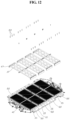
- Prior art date
- Legal status (The legal status is an assumption and is not a legal conclusion. Google has not performed a legal analysis and makes no representation as to the accuracy of the status listed.)
- Pending
Links
Images








Classifications
-
- H—ELECTRICITY
- H01—ELECTRIC ELEMENTS
- H01M—PROCESSES OR MEANS, e.g. BATTERIES, FOR THE DIRECT CONVERSION OF CHEMICAL ENERGY INTO ELECTRICAL ENERGY
- H01M50/00—Constructional details or processes of manufacture of the non-active parts of electrochemical cells other than fuel cells, e.g. hybrid cells
- H01M50/20—Mountings; Secondary casings or frames; Racks, modules or packs; Suspension devices; Shock absorbers; Transport or carrying devices; Holders
- H01M50/262—Mountings; Secondary casings or frames; Racks, modules or packs; Suspension devices; Shock absorbers; Transport or carrying devices; Holders with fastening means, e.g. locks
- H01M50/264—Mountings; Secondary casings or frames; Racks, modules or packs; Suspension devices; Shock absorbers; Transport or carrying devices; Holders with fastening means, e.g. locks for cells or batteries, e.g. straps, tie rods or peripheral frames
-
- H—ELECTRICITY
- H01—ELECTRIC ELEMENTS
- H01M—PROCESSES OR MEANS, e.g. BATTERIES, FOR THE DIRECT CONVERSION OF CHEMICAL ENERGY INTO ELECTRICAL ENERGY
- H01M50/00—Constructional details or processes of manufacture of the non-active parts of electrochemical cells other than fuel cells, e.g. hybrid cells
- H01M50/20—Mountings; Secondary casings or frames; Racks, modules or packs; Suspension devices; Shock absorbers; Transport or carrying devices; Holders
- H01M50/202—Casings or frames around the primary casing of a single cell or a single battery
-
- H—ELECTRICITY
- H01—ELECTRIC ELEMENTS
- H01M—PROCESSES OR MEANS, e.g. BATTERIES, FOR THE DIRECT CONVERSION OF CHEMICAL ENERGY INTO ELECTRICAL ENERGY
- H01M50/00—Constructional details or processes of manufacture of the non-active parts of electrochemical cells other than fuel cells, e.g. hybrid cells
- H01M50/20—Mountings; Secondary casings or frames; Racks, modules or packs; Suspension devices; Shock absorbers; Transport or carrying devices; Holders
- H01M50/204—Racks, modules or packs for multiple batteries or multiple cells
- H01M50/207—Racks, modules or packs for multiple batteries or multiple cells characterised by their shape
- H01M50/209—Racks, modules or packs for multiple batteries or multiple cells characterised by their shape adapted for prismatic or rectangular cells
-
- H—ELECTRICITY
- H01—ELECTRIC ELEMENTS
- H01M—PROCESSES OR MEANS, e.g. BATTERIES, FOR THE DIRECT CONVERSION OF CHEMICAL ENERGY INTO ELECTRICAL ENERGY
- H01M10/00—Secondary cells; Manufacture thereof
- H01M10/04—Construction or manufacture in general
- H01M10/0481—Compression means other than compression means for stacks of electrodes and separators
-
- H—ELECTRICITY
- H01—ELECTRIC ELEMENTS
- H01M—PROCESSES OR MEANS, e.g. BATTERIES, FOR THE DIRECT CONVERSION OF CHEMICAL ENERGY INTO ELECTRICAL ENERGY
- H01M10/00—Secondary cells; Manufacture thereof
- H01M10/42—Methods or arrangements for servicing or maintenance of secondary cells or secondary half-cells
- H01M10/425—Structural combination with electronic components, e.g. electronic circuits integrated to the outside of the casing
-
- H—ELECTRICITY
- H01—ELECTRIC ELEMENTS
- H01M—PROCESSES OR MEANS, e.g. BATTERIES, FOR THE DIRECT CONVERSION OF CHEMICAL ENERGY INTO ELECTRICAL ENERGY
- H01M10/00—Secondary cells; Manufacture thereof
- H01M10/42—Methods or arrangements for servicing or maintenance of secondary cells or secondary half-cells
- H01M10/48—Accumulators combined with arrangements for measuring, testing or indicating the condition of cells, e.g. the level or density of the electrolyte
-
- H—ELECTRICITY
- H01—ELECTRIC ELEMENTS
- H01M—PROCESSES OR MEANS, e.g. BATTERIES, FOR THE DIRECT CONVERSION OF CHEMICAL ENERGY INTO ELECTRICAL ENERGY
- H01M10/00—Secondary cells; Manufacture thereof
- H01M10/42—Methods or arrangements for servicing or maintenance of secondary cells or secondary half-cells
- H01M10/48—Accumulators combined with arrangements for measuring, testing or indicating the condition of cells, e.g. the level or density of the electrolyte
- H01M10/482—Accumulators combined with arrangements for measuring, testing or indicating the condition of cells, e.g. the level or density of the electrolyte for several batteries or cells simultaneously or sequentially
-
- H—ELECTRICITY
- H01—ELECTRIC ELEMENTS
- H01M—PROCESSES OR MEANS, e.g. BATTERIES, FOR THE DIRECT CONVERSION OF CHEMICAL ENERGY INTO ELECTRICAL ENERGY
- H01M10/00—Secondary cells; Manufacture thereof
- H01M10/42—Methods or arrangements for servicing or maintenance of secondary cells or secondary half-cells
- H01M10/48—Accumulators combined with arrangements for measuring, testing or indicating the condition of cells, e.g. the level or density of the electrolyte
- H01M10/486—Accumulators combined with arrangements for measuring, testing or indicating the condition of cells, e.g. the level or density of the electrolyte for measuring temperature
-
- H—ELECTRICITY
- H01—ELECTRIC ELEMENTS
- H01M—PROCESSES OR MEANS, e.g. BATTERIES, FOR THE DIRECT CONVERSION OF CHEMICAL ENERGY INTO ELECTRICAL ENERGY
- H01M10/00—Secondary cells; Manufacture thereof
- H01M10/60—Heating or cooling; Temperature control
- H01M10/64—Heating or cooling; Temperature control characterised by the shape of the cells
- H01M10/647—Prismatic or flat cells, e.g. pouch cells
-
- H—ELECTRICITY
- H01—ELECTRIC ELEMENTS
- H01M—PROCESSES OR MEANS, e.g. BATTERIES, FOR THE DIRECT CONVERSION OF CHEMICAL ENERGY INTO ELECTRICAL ENERGY
- H01M10/00—Secondary cells; Manufacture thereof
- H01M10/60—Heating or cooling; Temperature control
- H01M10/65—Means for temperature control structurally associated with the cells
- H01M10/655—Solid structures for heat exchange or heat conduction
- H01M10/6556—Solid parts with flow channel passages or pipes for heat exchange
- H01M10/6557—Solid parts with flow channel passages or pipes for heat exchange arranged between the cells
-
- H—ELECTRICITY
- H01—ELECTRIC ELEMENTS
- H01M—PROCESSES OR MEANS, e.g. BATTERIES, FOR THE DIRECT CONVERSION OF CHEMICAL ENERGY INTO ELECTRICAL ENERGY
- H01M50/00—Constructional details or processes of manufacture of the non-active parts of electrochemical cells other than fuel cells, e.g. hybrid cells
- H01M50/10—Primary casings; Jackets or wrappings
- H01M50/102—Primary casings; Jackets or wrappings characterised by their shape or physical structure
- H01M50/105—Pouches or flexible bags
-
- H—ELECTRICITY
- H01—ELECTRIC ELEMENTS
- H01M—PROCESSES OR MEANS, e.g. BATTERIES, FOR THE DIRECT CONVERSION OF CHEMICAL ENERGY INTO ELECTRICAL ENERGY
- H01M50/00—Constructional details or processes of manufacture of the non-active parts of electrochemical cells other than fuel cells, e.g. hybrid cells
- H01M50/20—Mountings; Secondary casings or frames; Racks, modules or packs; Suspension devices; Shock absorbers; Transport or carrying devices; Holders
- H01M50/204—Racks, modules or packs for multiple batteries or multiple cells
-
- H—ELECTRICITY
- H01—ELECTRIC ELEMENTS
- H01M—PROCESSES OR MEANS, e.g. BATTERIES, FOR THE DIRECT CONVERSION OF CHEMICAL ENERGY INTO ELECTRICAL ENERGY
- H01M50/00—Constructional details or processes of manufacture of the non-active parts of electrochemical cells other than fuel cells, e.g. hybrid cells
- H01M50/20—Mountings; Secondary casings or frames; Racks, modules or packs; Suspension devices; Shock absorbers; Transport or carrying devices; Holders
- H01M50/204—Racks, modules or packs for multiple batteries or multiple cells
- H01M50/207—Racks, modules or packs for multiple batteries or multiple cells characterised by their shape
- H01M50/211—Racks, modules or packs for multiple batteries or multiple cells characterised by their shape adapted for pouch cells
-
- H—ELECTRICITY
- H01—ELECTRIC ELEMENTS
- H01M—PROCESSES OR MEANS, e.g. BATTERIES, FOR THE DIRECT CONVERSION OF CHEMICAL ENERGY INTO ELECTRICAL ENERGY
- H01M50/00—Constructional details or processes of manufacture of the non-active parts of electrochemical cells other than fuel cells, e.g. hybrid cells
- H01M50/20—Mountings; Secondary casings or frames; Racks, modules or packs; Suspension devices; Shock absorbers; Transport or carrying devices; Holders
- H01M50/218—Mountings; Secondary casings or frames; Racks, modules or packs; Suspension devices; Shock absorbers; Transport or carrying devices; Holders characterised by the material
- H01M50/22—Mountings; Secondary casings or frames; Racks, modules or packs; Suspension devices; Shock absorbers; Transport or carrying devices; Holders characterised by the material of the casings or racks
- H01M50/222—Inorganic material
- H01M50/224—Metals
-
- H—ELECTRICITY
- H01—ELECTRIC ELEMENTS
- H01M—PROCESSES OR MEANS, e.g. BATTERIES, FOR THE DIRECT CONVERSION OF CHEMICAL ENERGY INTO ELECTRICAL ENERGY
- H01M50/00—Constructional details or processes of manufacture of the non-active parts of electrochemical cells other than fuel cells, e.g. hybrid cells
- H01M50/20—Mountings; Secondary casings or frames; Racks, modules or packs; Suspension devices; Shock absorbers; Transport or carrying devices; Holders
- H01M50/244—Secondary casings; Racks; Suspension devices; Carrying devices; Holders characterised by their mounting method
-
- H—ELECTRICITY
- H01—ELECTRIC ELEMENTS
- H01M—PROCESSES OR MEANS, e.g. BATTERIES, FOR THE DIRECT CONVERSION OF CHEMICAL ENERGY INTO ELECTRICAL ENERGY
- H01M50/00—Constructional details or processes of manufacture of the non-active parts of electrochemical cells other than fuel cells, e.g. hybrid cells
- H01M50/20—Mountings; Secondary casings or frames; Racks, modules or packs; Suspension devices; Shock absorbers; Transport or carrying devices; Holders
- H01M50/249—Mountings; Secondary casings or frames; Racks, modules or packs; Suspension devices; Shock absorbers; Transport or carrying devices; Holders specially adapted for aircraft or vehicles, e.g. cars or trains
-
- H—ELECTRICITY
- H01—ELECTRIC ELEMENTS
- H01M—PROCESSES OR MEANS, e.g. BATTERIES, FOR THE DIRECT CONVERSION OF CHEMICAL ENERGY INTO ELECTRICAL ENERGY
- H01M50/00—Constructional details or processes of manufacture of the non-active parts of electrochemical cells other than fuel cells, e.g. hybrid cells
- H01M50/20—Mountings; Secondary casings or frames; Racks, modules or packs; Suspension devices; Shock absorbers; Transport or carrying devices; Holders
- H01M50/258—Modular batteries; Casings provided with means for assembling
-
- H—ELECTRICITY
- H01—ELECTRIC ELEMENTS
- H01M—PROCESSES OR MEANS, e.g. BATTERIES, FOR THE DIRECT CONVERSION OF CHEMICAL ENERGY INTO ELECTRICAL ENERGY
- H01M50/00—Constructional details or processes of manufacture of the non-active parts of electrochemical cells other than fuel cells, e.g. hybrid cells
- H01M50/20—Mountings; Secondary casings or frames; Racks, modules or packs; Suspension devices; Shock absorbers; Transport or carrying devices; Holders
- H01M50/262—Mountings; Secondary casings or frames; Racks, modules or packs; Suspension devices; Shock absorbers; Transport or carrying devices; Holders with fastening means, e.g. locks
-
- H—ELECTRICITY
- H01—ELECTRIC ELEMENTS
- H01M—PROCESSES OR MEANS, e.g. BATTERIES, FOR THE DIRECT CONVERSION OF CHEMICAL ENERGY INTO ELECTRICAL ENERGY
- H01M50/00—Constructional details or processes of manufacture of the non-active parts of electrochemical cells other than fuel cells, e.g. hybrid cells
- H01M50/20—Mountings; Secondary casings or frames; Racks, modules or packs; Suspension devices; Shock absorbers; Transport or carrying devices; Holders
- H01M50/271—Lids or covers for the racks or secondary casings
-
- H—ELECTRICITY
- H01—ELECTRIC ELEMENTS
- H01M—PROCESSES OR MEANS, e.g. BATTERIES, FOR THE DIRECT CONVERSION OF CHEMICAL ENERGY INTO ELECTRICAL ENERGY
- H01M50/00—Constructional details or processes of manufacture of the non-active parts of electrochemical cells other than fuel cells, e.g. hybrid cells
- H01M50/20—Mountings; Secondary casings or frames; Racks, modules or packs; Suspension devices; Shock absorbers; Transport or carrying devices; Holders
- H01M50/284—Mountings; Secondary casings or frames; Racks, modules or packs; Suspension devices; Shock absorbers; Transport or carrying devices; Holders with incorporated circuit boards, e.g. printed circuit boards [PCB]
-
- H—ELECTRICITY
- H01—ELECTRIC ELEMENTS
- H01M—PROCESSES OR MEANS, e.g. BATTERIES, FOR THE DIRECT CONVERSION OF CHEMICAL ENERGY INTO ELECTRICAL ENERGY
- H01M50/00—Constructional details or processes of manufacture of the non-active parts of electrochemical cells other than fuel cells, e.g. hybrid cells
- H01M50/20—Mountings; Secondary casings or frames; Racks, modules or packs; Suspension devices; Shock absorbers; Transport or carrying devices; Holders
- H01M50/289—Mountings; Secondary casings or frames; Racks, modules or packs; Suspension devices; Shock absorbers; Transport or carrying devices; Holders characterised by spacing elements or positioning means within frames, racks or packs
-
- H—ELECTRICITY
- H01—ELECTRIC ELEMENTS
- H01M—PROCESSES OR MEANS, e.g. BATTERIES, FOR THE DIRECT CONVERSION OF CHEMICAL ENERGY INTO ELECTRICAL ENERGY
- H01M50/00—Constructional details or processes of manufacture of the non-active parts of electrochemical cells other than fuel cells, e.g. hybrid cells
- H01M50/20—Mountings; Secondary casings or frames; Racks, modules or packs; Suspension devices; Shock absorbers; Transport or carrying devices; Holders
- H01M50/289—Mountings; Secondary casings or frames; Racks, modules or packs; Suspension devices; Shock absorbers; Transport or carrying devices; Holders characterised by spacing elements or positioning means within frames, racks or packs
- H01M50/291—Mountings; Secondary casings or frames; Racks, modules or packs; Suspension devices; Shock absorbers; Transport or carrying devices; Holders characterised by spacing elements or positioning means within frames, racks or packs characterised by their shape
-
- H—ELECTRICITY
- H01—ELECTRIC ELEMENTS
- H01M—PROCESSES OR MEANS, e.g. BATTERIES, FOR THE DIRECT CONVERSION OF CHEMICAL ENERGY INTO ELECTRICAL ENERGY
- H01M50/00—Constructional details or processes of manufacture of the non-active parts of electrochemical cells other than fuel cells, e.g. hybrid cells
- H01M50/20—Mountings; Secondary casings or frames; Racks, modules or packs; Suspension devices; Shock absorbers; Transport or carrying devices; Holders
- H01M50/296—Mountings; Secondary casings or frames; Racks, modules or packs; Suspension devices; Shock absorbers; Transport or carrying devices; Holders characterised by terminals of battery packs
-
- H—ELECTRICITY
- H01—ELECTRIC ELEMENTS
- H01M—PROCESSES OR MEANS, e.g. BATTERIES, FOR THE DIRECT CONVERSION OF CHEMICAL ENERGY INTO ELECTRICAL ENERGY
- H01M50/00—Constructional details or processes of manufacture of the non-active parts of electrochemical cells other than fuel cells, e.g. hybrid cells
- H01M50/50—Current conducting connections for cells or batteries
-
- H—ELECTRICITY
- H01—ELECTRIC ELEMENTS
- H01M—PROCESSES OR MEANS, e.g. BATTERIES, FOR THE DIRECT CONVERSION OF CHEMICAL ENERGY INTO ELECTRICAL ENERGY
- H01M50/00—Constructional details or processes of manufacture of the non-active parts of electrochemical cells other than fuel cells, e.g. hybrid cells
- H01M50/50—Current conducting connections for cells or batteries
- H01M50/502—Interconnectors for connecting terminals of adjacent batteries; Interconnectors for connecting cells outside a battery casing
- H01M50/503—Interconnectors for connecting terminals of adjacent batteries; Interconnectors for connecting cells outside a battery casing characterised by the shape of the interconnectors
-
- H—ELECTRICITY
- H01—ELECTRIC ELEMENTS
- H01M—PROCESSES OR MEANS, e.g. BATTERIES, FOR THE DIRECT CONVERSION OF CHEMICAL ENERGY INTO ELECTRICAL ENERGY
- H01M50/00—Constructional details or processes of manufacture of the non-active parts of electrochemical cells other than fuel cells, e.g. hybrid cells
- H01M50/50—Current conducting connections for cells or batteries
- H01M50/502—Interconnectors for connecting terminals of adjacent batteries; Interconnectors for connecting cells outside a battery casing
- H01M50/505—Interconnectors for connecting terminals of adjacent batteries; Interconnectors for connecting cells outside a battery casing comprising a single busbar
-
- H—ELECTRICITY
- H01—ELECTRIC ELEMENTS
- H01M—PROCESSES OR MEANS, e.g. BATTERIES, FOR THE DIRECT CONVERSION OF CHEMICAL ENERGY INTO ELECTRICAL ENERGY
- H01M50/00—Constructional details or processes of manufacture of the non-active parts of electrochemical cells other than fuel cells, e.g. hybrid cells
- H01M50/50—Current conducting connections for cells or batteries
- H01M50/502—Interconnectors for connecting terminals of adjacent batteries; Interconnectors for connecting cells outside a battery casing
- H01M50/507—Interconnectors for connecting terminals of adjacent batteries; Interconnectors for connecting cells outside a battery casing comprising an arrangement of two or more busbars within a container structure, e.g. busbar modules
-
- H—ELECTRICITY
- H01—ELECTRIC ELEMENTS
- H01M—PROCESSES OR MEANS, e.g. BATTERIES, FOR THE DIRECT CONVERSION OF CHEMICAL ENERGY INTO ELECTRICAL ENERGY
- H01M50/00—Constructional details or processes of manufacture of the non-active parts of electrochemical cells other than fuel cells, e.g. hybrid cells
- H01M50/50—Current conducting connections for cells or batteries
- H01M50/502—Interconnectors for connecting terminals of adjacent batteries; Interconnectors for connecting cells outside a battery casing
- H01M50/509—Interconnectors for connecting terminals of adjacent batteries; Interconnectors for connecting cells outside a battery casing characterised by the type of connection, e.g. mixed connections
-
- H—ELECTRICITY
- H01—ELECTRIC ELEMENTS
- H01M—PROCESSES OR MEANS, e.g. BATTERIES, FOR THE DIRECT CONVERSION OF CHEMICAL ENERGY INTO ELECTRICAL ENERGY
- H01M50/00—Constructional details or processes of manufacture of the non-active parts of electrochemical cells other than fuel cells, e.g. hybrid cells
- H01M50/50—Current conducting connections for cells or batteries
- H01M50/502—Interconnectors for connecting terminals of adjacent batteries; Interconnectors for connecting cells outside a battery casing
- H01M50/509—Interconnectors for connecting terminals of adjacent batteries; Interconnectors for connecting cells outside a battery casing characterised by the type of connection, e.g. mixed connections
- H01M50/51—Connection only in series
-
- H—ELECTRICITY
- H01—ELECTRIC ELEMENTS
- H01M—PROCESSES OR MEANS, e.g. BATTERIES, FOR THE DIRECT CONVERSION OF CHEMICAL ENERGY INTO ELECTRICAL ENERGY
- H01M50/00—Constructional details or processes of manufacture of the non-active parts of electrochemical cells other than fuel cells, e.g. hybrid cells
- H01M50/50—Current conducting connections for cells or batteries
- H01M50/502—Interconnectors for connecting terminals of adjacent batteries; Interconnectors for connecting cells outside a battery casing
- H01M50/514—Methods for interconnecting adjacent batteries or cells
- H01M50/516—Methods for interconnecting adjacent batteries or cells by welding, soldering or brazing
-
- H—ELECTRICITY
- H01—ELECTRIC ELEMENTS
- H01M—PROCESSES OR MEANS, e.g. BATTERIES, FOR THE DIRECT CONVERSION OF CHEMICAL ENERGY INTO ELECTRICAL ENERGY
- H01M50/00—Constructional details or processes of manufacture of the non-active parts of electrochemical cells other than fuel cells, e.g. hybrid cells
- H01M50/50—Current conducting connections for cells or batteries
- H01M50/502—Interconnectors for connecting terminals of adjacent batteries; Interconnectors for connecting cells outside a battery casing
- H01M50/519—Interconnectors for connecting terminals of adjacent batteries; Interconnectors for connecting cells outside a battery casing comprising printed circuit boards [PCB]
-
- H—ELECTRICITY
- H01—ELECTRIC ELEMENTS
- H01M—PROCESSES OR MEANS, e.g. BATTERIES, FOR THE DIRECT CONVERSION OF CHEMICAL ENERGY INTO ELECTRICAL ENERGY
- H01M50/00—Constructional details or processes of manufacture of the non-active parts of electrochemical cells other than fuel cells, e.g. hybrid cells
- H01M50/50—Current conducting connections for cells or batteries
- H01M50/502—Interconnectors for connecting terminals of adjacent batteries; Interconnectors for connecting cells outside a battery casing
- H01M50/521—Interconnectors for connecting terminals of adjacent batteries; Interconnectors for connecting cells outside a battery casing characterised by the material
- H01M50/522—Inorganic material
-
- H—ELECTRICITY
- H01—ELECTRIC ELEMENTS
- H01M—PROCESSES OR MEANS, e.g. BATTERIES, FOR THE DIRECT CONVERSION OF CHEMICAL ENERGY INTO ELECTRICAL ENERGY
- H01M50/00—Constructional details or processes of manufacture of the non-active parts of electrochemical cells other than fuel cells, e.g. hybrid cells
- H01M50/50—Current conducting connections for cells or batteries
- H01M50/543—Terminals
- H01M50/547—Terminals characterised by the disposition of the terminals on the cells
- H01M50/548—Terminals characterised by the disposition of the terminals on the cells on opposite sides of the cell
-
- H—ELECTRICITY
- H01—ELECTRIC ELEMENTS
- H01M—PROCESSES OR MEANS, e.g. BATTERIES, FOR THE DIRECT CONVERSION OF CHEMICAL ENERGY INTO ELECTRICAL ENERGY
- H01M50/00—Constructional details or processes of manufacture of the non-active parts of electrochemical cells other than fuel cells, e.g. hybrid cells
- H01M50/50—Current conducting connections for cells or batteries
- H01M50/543—Terminals
- H01M50/552—Terminals characterised by their shape
- H01M50/553—Terminals adapted for prismatic, pouch or rectangular cells
-
- H—ELECTRICITY
- H01—ELECTRIC ELEMENTS
- H01M—PROCESSES OR MEANS, e.g. BATTERIES, FOR THE DIRECT CONVERSION OF CHEMICAL ENERGY INTO ELECTRICAL ENERGY
- H01M50/00—Constructional details or processes of manufacture of the non-active parts of electrochemical cells other than fuel cells, e.g. hybrid cells
- H01M50/50—Current conducting connections for cells or batteries
- H01M50/569—Constructional details of current conducting connections for detecting conditions inside cells or batteries, e.g. details of voltage sensing terminals
-
- B—PERFORMING OPERATIONS; TRANSPORTING
- B60—VEHICLES IN GENERAL
- B60L—PROPULSION OF ELECTRICALLY-PROPELLED VEHICLES; SUPPLYING ELECTRIC POWER FOR AUXILIARY EQUIPMENT OF ELECTRICALLY-PROPELLED VEHICLES; ELECTRODYNAMIC BRAKE SYSTEMS FOR VEHICLES IN GENERAL; MAGNETIC SUSPENSION OR LEVITATION FOR VEHICLES; MONITORING OPERATING VARIABLES OF ELECTRICALLY-PROPELLED VEHICLES; ELECTRIC SAFETY DEVICES FOR ELECTRICALLY-PROPELLED VEHICLES
- B60L50/00—Electric propulsion with power supplied within the vehicle
- B60L50/50—Electric propulsion with power supplied within the vehicle using propulsion power supplied by batteries or fuel cells
- B60L50/60—Electric propulsion with power supplied within the vehicle using propulsion power supplied by batteries or fuel cells using power supplied by batteries
- B60L50/64—Constructional details of batteries specially adapted for electric vehicles
-
- B—PERFORMING OPERATIONS; TRANSPORTING
- B60—VEHICLES IN GENERAL
- B60Y—INDEXING SCHEME RELATING TO ASPECTS CROSS-CUTTING VEHICLE TECHNOLOGY
- B60Y2200/00—Type of vehicle
- B60Y2200/90—Vehicles comprising electric prime movers
- B60Y2200/91—Electric vehicles
-
- H—ELECTRICITY
- H01—ELECTRIC ELEMENTS
- H01M—PROCESSES OR MEANS, e.g. BATTERIES, FOR THE DIRECT CONVERSION OF CHEMICAL ENERGY INTO ELECTRICAL ENERGY
- H01M10/00—Secondary cells; Manufacture thereof
- H01M10/42—Methods or arrangements for servicing or maintenance of secondary cells or secondary half-cells
- H01M10/425—Structural combination with electronic components, e.g. electronic circuits integrated to the outside of the casing
- H01M2010/4271—Battery management systems including electronic circuits, e.g. control of current or voltage to keep battery in healthy state, cell balancing
-
- H—ELECTRICITY
- H01—ELECTRIC ELEMENTS
- H01M—PROCESSES OR MEANS, e.g. BATTERIES, FOR THE DIRECT CONVERSION OF CHEMICAL ENERGY INTO ELECTRICAL ENERGY
- H01M2220/00—Batteries for particular applications
- H01M2220/20—Batteries in motive systems, e.g. vehicle, ship, plane
-
- Y—GENERAL TAGGING OF NEW TECHNOLOGICAL DEVELOPMENTS; GENERAL TAGGING OF CROSS-SECTIONAL TECHNOLOGIES SPANNING OVER SEVERAL SECTIONS OF THE IPC; TECHNICAL SUBJECTS COVERED BY FORMER USPC CROSS-REFERENCE ART COLLECTIONS [XRACs] AND DIGESTS
- Y02—TECHNOLOGIES OR APPLICATIONS FOR MITIGATION OR ADAPTATION AGAINST CLIMATE CHANGE
- Y02E—REDUCTION OF GREENHOUSE GAS [GHG] EMISSIONS, RELATED TO ENERGY GENERATION, TRANSMISSION OR DISTRIBUTION
- Y02E60/00—Enabling technologies; Technologies with a potential or indirect contribution to GHG emissions mitigation
- Y02E60/10—Energy storage using batteries
Definitions
- Embodiments of the present disclosure relate generally to a structure of a battery pack used in an electric vehicle, etc.
- a battery pack mounted in an electric vehicle, etc. has a plurality of battery cells.
- the plurality of battery cells are coupled to each other to form a battery module, and a plurality of battery modules are coupled to each other to form a battery pack.
- the battery module imparts mechanical rigidity to pouch-type battery cells and facilitate forming the battery pack.
- an end plate, etc. included in the battery module occupies the internal space of the battery pack, and as a result, the number of the battery cells that can be accommodated in the battery pack is reduced and it is an obstacle to maximizing energy density of the battery pack.
- controller and the controlling method of operating a fuel cell is intended merely to aid in the understanding of the background of embodiments of the present disclosure, and is not intended to mean that embodiments of the present disclosure fall within the purview of the related art that is already known to those skilled in the art.
- embodiments of the present disclosure have been made keeping in mind the above problem occurring in the related art, and embodiments of the present disclosure are intended to provide a battery pack for a vehicle, wherein the battery pack, which is to have pouch-type battery cells built therein, is configured such that as many battery cells as possible are built therein to maximize energy density thereof, the battery cells are relatively easily built into the battery pack, and solid durability of the battery cells built in the battery pack is secured.
- a battery pack for a vehicle including: a battery unit including a plurality of battery cells overlapped with each other; unit busbars respectively coupled to electrodes at opposite ends of the battery cells constituting the battery unit, the unit busbars being extended upward from the battery unit; unit busbar support bodies located at opposite ends of the battery unit and supporting both the unit busbars and the battery cells; a lower tray on which battery units may be loaded while being overlapped with each other, the lower tray supporting lower surfaces and side surfaces of the overlapped battery units; a pressing plate disposed between each of side walls of the lower tray and the battery units, and configured to press the battery units in an overlapped direction of the battery units; and a top cover forcibly coupled to the overlapped battery units in a downward direction so as to cover upper portions of the overlapped battery units, and configured to supply pressure for the pressing plate to press the battery units.
- the battery unit may be configured such that two battery cells may be overlapped with each other with a compressed pad provided between the two battery cells; and each of the unit busbars may be coupled to the electrodes of the overlapped two battery cells.
- Each of the unit busbar support bodies may include a unit busbar housing and an unit busbar cover, the unit busbar housing supporting a gap between the battery cells and each of the unit busbars and the unit busbar cover being coupled to the unit busbar housing with the unit busbar located between the unit busbar housing and the unit busbar cover and covering an outer portion of the unit busbar.
- Each of the unit busbar support bodies may have a restriction protrusion and a restriction groove at positions corresponding to each other so as to restrain a relative location in response to another unit busbar support body overlapped with each other.
- the lower tray may include a center member at a center portion thereof and the side walls at side portions thereof; and a plurality of battery units may be arranged to be overlapped with each other between the center member and each of the side walls.
- the pressing plate may have a flat surface facing the battery units and an inclined surface opposite to the flat surface, the inclined surface protruding to be gradually inclined outward in the downward direction.
- the top cover may include wedge portions integrally formed on lower portions of opposite ends, the wedge portions being configured to press the inclined surface of the pressing plate while being moved downward, so that the pressing plate may press the overlapped battery units toward the center member.
- Each of the side walls of the lower tray may have an inner protrusion at a lower portion thereof, the inner protrusion protruding toward the overlapped battery units; and the pressing plate may have a guide surface, the guide surface constituting a triangle together with the inclined surface and being in surface-contact with an upper surface of the inner protrusion and being configured to guide the pressing plate when the pressing plate is moved toward the battery units.
- the battery pack may include: a plurality of pressure bolts configured to press each of the wedge portions of the top cover toward the inner protrusion of the lower tray, wherein the inclined surface and the guide surface of the pressing plate may respectively have a plurality of through holes, and the plurality of through holes may allow the pressing plate to be moved while the plurality of pressure bolts pass through the pressing plate.
- the battery pack may include: a sensing assembly provided above the top cover, the sensing assembly being configured to electrically connect the unit busbars of the battery units loaded on the lower tray to each other, wherein the sensing assembly may be formed in a single flat plate integrated with a high current busbar connecting all the battery units loaded on the lower tray to each other in series.
- the high current busbar may include: a plurality of inter-busbars arranged in rows at predetermined intervals in an overlapped direction of the battery units so as to connect the unit busbars of the battery units located adjacent to each other; and a plurality of long busbars arranged obliquely across the overlapped battery units so that the rows of the inter-busbars may be connected to each other.
- the sensing assembly may include a plurality of temperature sensors measuring temperatures of the battery units.
- the sensing assembly may include a plurality of center monitor unit (CMU) connectors configured to transmit a voltage of each of the battery cells constituting each of the battery units and data of the temperature sensors to a CMU
- CMU center monitor unit
- the sensing assembly may include a FPCB integrally provided, the FPCB may be connected to the plurality of inter-busbars, the plurality of temperature sensors, and the plurality of CMU connectors so as to transmit the voltage and temperature information of each of the battery units through the CMU connectors.
- the top cover may be formed with a width narrower than a length of each of the battery units so that the unit busbars of the battery unit may be exposed upward; and the high current busbar of the sensing assembly may be weld to the upper surfaces of the unit busbars of the battery units exposed through opposite sides of the top cover.
- the battery pack to have the pouch-type battery cells built therein can have as many battery cells as possible, so that energy density of the battery pack can be maximized, and the battery cells can be relatively easily built in the battery pack and solid durability of the battery cells built in the battery pack can be secured.
- the method and apparatus suitably include use of a controller or processer.
- vehicles are provided that comprise an apparatus as disclosed herein.
- vehicle or “vehicular” or other similar term as used herein is inclusive of motor vehicles in general such as passenger automobiles including sports utility vehicles (SUV), buses, trucks, various commercial vehicles, watercraft including a variety of boats and ships, aircraft, and the like, and includes hybrid vehicles, electric vehicles, plug-in hybrid electric vehicles, hydrogen-powered vehicles and other alternative fuel vehicles (e.g. fuels derived from resources other than petroleum).
- a hybrid vehicle is a vehicle that has two or more sources of power, for example both gasoline-powered and electric-powered vehicles.
- control logic of embodiments of the present disclosure may be embodied as non-transitory computer readable media on a computer readable medium containing executable program instructions executed by a processor, controller, or the like.
- Examples of computer readable media include, but are not limited to, ROM, RAM, compact disc (CD)-ROMs, magnetic tapes, floppy disks, flash drives, smart cards, and optical data storage devices.
- the computer readable medium can also be distributed in network coupled computer systems so that the computer readable media is stored and executed in a distributed fashion, e.g., by a telematics server or a Controller Area Network (CAN)
- a telematics server or a Controller Area Network (CAN)
- first and/or second, etc. may be used herein to describe various elements, these elements should not be limited by these terms. These terms are only used to distinguish one element, from another element. For instance, a first element discussed below could be termed a second element without departing from the teachings of embodiments of the present disclosure. Similarly, the second element could also be termed the first element.
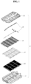
- a battery pack 1 for a vehicle may include: a battery unit 5 comprising battery cells 3 overlapped with each other; unit busbars 7 respectively connected to electrodes at opposite ends of the battery cells 3 constituting the battery unit 5, and extended upward from the battery unit 5; unit busbar support bodies 9 located at opposite ends of the battery unit 5 and supporting the unit busbars 7 and the battery cells 3; a lower tray 11 on which battery units 5 are loaded while being overlapped with each other, the lower tray 11 supporting lower surfaces and side surfaces of the overlapped battery units 5; a pressing plate 15 disposed between each of side walls 13 of the lower tray 11 and the battery units 5, and configured to press the battery units 5 in an overlapped direction of the battery units 5; and a top cover 17 forcibly coupled to the overlapped battery units 5 in a downward direction so as to cover upper portions of the overlapped battery units 5, and configured to supply pressure for the pressing plate 15 to press the battery units 5.
- a sensing assembly 19 may be provided above the top cover 17 to electrically connect the unit busbars 7 of the battery units 5 loaded on the lower tray 11 to each other.
- An upper casing 21 may be coupled to an upper portion of the sensing assembly 19 thus forming a battery pack 1.
- FIG. 1 For example, a wiring 23 promoting various electric connections between the upper casing 21 and the sensing assembly 19 is presented in FIG. 1 .
- 5S indicates the overlapped battery units.
- the battery unit 5 may be configured such that two battery cells 3 are overlapped with each other with a compressed pad 25 provided between the two battery cells 3; and the unit busbars 7 are respectively coupled to the electrodes of the two overlapped battery cells 3.
- Each of the unit busbar support bodies 9 may include a unit busbar housing 27 and a unit busbar cover 29.
- the unit busbar housing 27 may support a gap between the battery cells 3 and each of the unit busbars 7, and the unit busbar cover 29 may be coupled to the unit busbar housing 27 with the unit busbar 7 located between the unit busbar cover 29 and the unit busbar housing 27 and may cover an outer portion of the unit busbar 7.
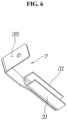
- FIG. 6 is a view showing the unit busbar 7.
- the unit busbar 7 may include: two electrode coupling portions 31 respectively coupled to the opposite electrodes of the two battery cells 3; and an upper exposed portion 35 extended upward from the battery unit 5 and coupled to inter-busbars 33 of the sensing assembly 19 by welding, the inter-busbars 33 of the sensing assembly 19 will be described later.
- the two battery cells 3 of the battery unit 5 may be arranged such that electrodes with same polarity are coupled to the same unit busbar 7, and electrodes with opposite polarities may be arranged in overlapped battery units 5 adjacent to each other. Therefore, when the unit busbars 7 of the two battery units 5 located adjacent to each other may be connected to each other by the inter-busbars 33, the overlapped battery units 5 are connected to each other in series.
- Each of the unit busbar support bodies 9 may include a restriction protrusion 37 and a restriction groove 39 to restrain a relative location with respect to another overlapped unit busbar support body 9.
- the restriction protrusion 37 may protrude on a first surface of the battery unit 5 and the restriction groove 39 is formed on a position corresponding to the restriction protrusion 37 in a second surface of the battery unit 5. Therefore, the two battery units 5 that are overlapped adjacent to each other may be relatively constrained in positional relationship. Consequently, it is possible to stably maintain an overlapped state of the plurality of battery units 5 that are arranged adjacent to each other in order.
- the lower tray 11 may include a center member 41 at a center portion thereof and the side walls 13 at side portions thereof.
- the plurality of battery units 5 au be loaded between the center member 41 and each of the side walls 13 of the lower tray 11 while being overlapped with each other.
- the plurality of battery units 5 in the overlapped state may be loaded on opposite portions of the lower tray 11 based on the center member 41 of the lower tray 11.
- the pressing plate 15 may be provided between the overlapped battery units 5 loaded on the lower tray 11 and the side walls 13 of the lower tray 11, and the pressing plate 15 presses the overlapped battery units 5 toward the sensing member. Accordingly, structural stability of the overlapped battery units 5 may be secured and surface pressure of the battery cells 3 constituting the battery units 5 may be secured.
- the battery pack of embodiments of the present disclosure does not require parts such as the end plate, etc., but additional battery cells may be loaded. Therefore, a larger number of battery cells are loaded on the lower tray substantially the same volume, and the energy density of the battery pack may be ultimately increased.
- the pressing plate 15 may include a flat surface facing the battery unit 5 and an inclined surface 43 opposite to the flat surface.
- the inclined surface 43 may protrude to be gradually inclined in the downward direction.
- the pressing plate 15 may be an aluminum extrusion material and may include an insulation film 45 on the surface of the pressing plate 15, the surface facing the battery unit 5.
- the top cover 17 may include wedge portions 47 integrally formed on lower portions of opposite ends thereof. Each of the wedge portions 47 may press the inclined surface 43 of the pressing plate 15 while being moved downward, so that the pressing plate 15 presses the overlapped battery units 5 toward the center member 41.
- each of the wedge portions 47 may be pressed downward between the pressing plate 15 and the side walls 13 of the lower tray 11, thereby generating a pressure for the pressing plate 15 to press the overlapped battery units 5 toward the center member 41.
- each of the side walls 13 of the lower tray 11 may have an inner protrusion 49 at a lower portion thereof and the inner protrusion protrudes toward the overlapped battery units 5.
- the pressing plate 15 may include a guide surface 51, and the guide surface 51 may constitute a triangle together with the inclined surface 43 and may be in surface-contact with an upper surface of the inner protrusion 49 so as to guide the pressing plate 15 when the pressing plate 15 is moved toward the battery unit 5.
- the battery pack may include a plurality of pressure bolts 53 to press the wedge portions 47 of the top cover 17 toward the inner protrusion 49 of the lower tray 11.
- the inclined surface 43 and the guide surface 51 of the pressing plate 15 may include a plurality of through holes 55 as shown in FIG. 8 .
- the plurality of through holes 55 may be provided to allow movement of the pressing plate 15 while the pressure bolts 53 pass through the pressing plate 15.
- the wedge portion 47 of the top cover 17 is pressed toward the inner protrusion 49 of the lower tray 11.
- the pressing plate 15 may press the battery units 5 toward the center member 41.
- the guide surface 51 of the pressing plate 15 may be guided by the upper surface of the inner protrusion 49 of the side walls 13 of the lower tray 11, and the movement of the pressing plate 15 may be freely allowed by the through holes 55 even with the pressure bolts 53.
- FIG. 12 is a view showing coupling the wedge portions 47 of the top cover 17 to the inner protrusion 49 of the lower tray 11 by the plurality of pressure bolts 53.
- the sensing assembly 19 may be formed in a single flat plate integrated with a high current busbar 57 connecting all the battery units 5 loaded on the lower tray 11 to each other in series.
- the high current busbar 57 may include the plurality of inter-busbars 33 and a plurality of long busbars 59.
- the plurality of inter-busbars 33 may be arranged in rows at predetermined intervals in the overlapped direction of the battery units 5 so as to connect the unit busbars 7 of the battery units 5 located adjacent to each other, and the plurality of long busbars 59 may be arranged obliquely across the overlapped battery units 5 so that the rows of the inter-busbars 33 are connected to each other.
- the sensing assembly 19 may include a plurality of temperature sensors 61 to measure the temperature of the battery units 5.
- the sensing assembly 19 may include a plurality of CMU connectors 63 provided to transmit a voltage of each of the battery cells 3 constituting the battery units 5 and data of the temperature sensors 61 to a cell monitoring unit (CMU)
- CMU cell monitoring unit
- FIG. 14 is a bottom view showing the sensing assembly 19 shown in FIG. 13 , and the plurality of CMU connectors 63 is presented in the drawing.
- the sensing assembly 19 may include a flexible printed circuit board (FPCB) integrally provided.
- the FPCB may be connected to the inter-busbars 33, the temperature sensors 61, and the CMU connectors 63 so as to transmit the voltage and temperature information of each battery unit 5 to the CMU through the CMU connectors 63.
- a fuse may be connected to location A and a power relay assembly (PRA) may be connected to location B.
- PRA power relay assembly
- the top cover 17 may be formed with the width narrower than the length of each of the battery units 5 so that the unit busbars 7 of the battery units 5 are exposed upward.
- the high current busbar 57 of the sensing assembly 19 may be weld to upper surfaces of the unit busbars 7 of the battery units 5 exposed through opposite sides of the top cover 17.
- the inter-busbars 33 of the sensing assembly 19 may be located on the upper surfaces (upper exposed portions) of the unit busbars 7 of the battery units 5, and the sensing assembly 19 and the battery units 5 may be easily coupled to each other by welding.
Landscapes
- Chemical & Material Sciences (AREA)
- Chemical Kinetics & Catalysis (AREA)
- Electrochemistry (AREA)
- General Chemical & Material Sciences (AREA)
- Engineering & Computer Science (AREA)
- Manufacturing & Machinery (AREA)
- Aviation & Aerospace Engineering (AREA)
- Microelectronics & Electronic Packaging (AREA)
- Inorganic Chemistry (AREA)
- Battery Mounting, Suspending (AREA)
- Connection Of Batteries Or Terminals (AREA)
Abstract
Description
- Embodiments of the present disclosure relate generally to a structure of a battery pack used in an electric vehicle, etc.
- A battery pack mounted in an electric vehicle, etc. has a plurality of battery cells. In general, the plurality of battery cells are coupled to each other to form a battery module, and a plurality of battery modules are coupled to each other to form a battery pack.
- The battery module imparts mechanical rigidity to pouch-type battery cells and facilitate forming the battery pack. However, an end plate, etc. included in the battery module occupies the internal space of the battery pack, and as a result, the number of the battery cells that can be accommodated in the battery pack is reduced and it is an obstacle to maximizing energy density of the battery pack.
- The foregoing described as the controller and the controlling method of operating a fuel cell is intended merely to aid in the understanding of the background of embodiments of the present disclosure, and is not intended to mean that embodiments of the present disclosure fall within the purview of the related art that is already known to those skilled in the art.
- Accordingly, embodiments of the present disclosure have been made keeping in mind the above problem occurring in the related art, and embodiments of the present disclosure are intended to provide a battery pack for a vehicle, wherein the battery pack, which is to have pouch-type battery cells built therein, is configured such that as many battery cells as possible are built therein to maximize energy density thereof, the battery cells are relatively easily built into the battery pack, and solid durability of the battery cells built in the battery pack is secured.
- In order to achieve the above objective, according to one exemplary embodiment of the present disclosure, there is provided a battery pack for a vehicle, the battery pack including: a battery unit including a plurality of battery cells overlapped with each other; unit busbars respectively coupled to electrodes at opposite ends of the battery cells constituting the battery unit, the unit busbars being extended upward from the battery unit; unit busbar support bodies located at opposite ends of the battery unit and supporting both the unit busbars and the battery cells; a lower tray on which battery units may be loaded while being overlapped with each other, the lower tray supporting lower surfaces and side surfaces of the overlapped battery units; a pressing plate disposed between each of side walls of the lower tray and the battery units, and configured to press the battery units in an overlapped direction of the battery units; and a top cover forcibly coupled to the overlapped battery units in a downward direction so as to cover upper portions of the overlapped battery units, and configured to supply pressure for the pressing plate to press the battery units.
- The battery unit may be configured such that two battery cells may be overlapped with each other with a compressed pad provided between the two battery cells; and each of the unit busbars may be coupled to the electrodes of the overlapped two battery cells.
- Each of the unit busbar support bodies may include a unit busbar housing and an unit busbar cover, the unit busbar housing supporting a gap between the battery cells and each of the unit busbars and the unit busbar cover being coupled to the unit busbar housing with the unit busbar located between the unit busbar housing and the unit busbar cover and covering an outer portion of the unit busbar.
- Each of the unit busbar support bodies may have a restriction protrusion and a restriction groove at positions corresponding to each other so as to restrain a relative location in response to another unit busbar support body overlapped with each other.
- The lower tray may include a center member at a center portion thereof and the side walls at side portions thereof; and a plurality of battery units may be arranged to be overlapped with each other between the center member and each of the side walls.
- The pressing plate may have a flat surface facing the battery units and an inclined surface opposite to the flat surface, the inclined surface protruding to be gradually inclined outward in the downward direction.
- The top cover may include wedge portions integrally formed on lower portions of opposite ends, the wedge portions being configured to press the inclined surface of the pressing plate while being moved downward, so that the pressing plate may press the overlapped battery units toward the center member.
- Each of the side walls of the lower tray may have an inner protrusion at a lower portion thereof, the inner protrusion protruding toward the overlapped battery units; and the pressing plate may have a guide surface, the guide surface constituting a triangle together with the inclined surface and being in surface-contact with an upper surface of the inner protrusion and being configured to guide the pressing plate when the pressing plate is moved toward the battery units.
- The battery pack may include: a plurality of pressure bolts configured to press each of the wedge portions of the top cover toward the inner protrusion of the lower tray, wherein the inclined surface and the guide surface of the pressing plate may respectively have a plurality of through holes, and the plurality of through holes may allow the pressing plate to be moved while the plurality of pressure bolts pass through the pressing plate.
- The battery pack may include: a sensing assembly provided above the top cover, the sensing assembly being configured to electrically connect the unit busbars of the battery units loaded on the lower tray to each other, wherein the sensing assembly may be formed in a single flat plate integrated with a high current busbar connecting all the battery units loaded on the lower tray to each other in series.
- The high current busbar may include: a plurality of inter-busbars arranged in rows at predetermined intervals in an overlapped direction of the battery units so as to connect the unit busbars of the battery units located adjacent to each other; and a plurality of long busbars arranged obliquely across the overlapped battery units so that the rows of the inter-busbars may be connected to each other.
- The sensing assembly may include a plurality of temperature sensors measuring temperatures of the battery units.
- The sensing assembly may include a plurality of center monitor unit (CMU) connectors configured to transmit a voltage of each of the battery cells constituting each of the battery units and data of the temperature sensors to a CMU
- The sensing assembly may include a FPCB integrally provided, the FPCB may be connected to the plurality of inter-busbars, the plurality of temperature sensors, and the plurality of CMU connectors so as to transmit the voltage and temperature information of each of the battery units through the CMU connectors.
- The top cover may be formed with a width narrower than a length of each of the battery units so that the unit busbars of the battery unit may be exposed upward; and the high current busbar of the sensing assembly may be weld to the upper surfaces of the unit busbars of the battery units exposed through opposite sides of the top cover.
- According to embodiments of the present disclosure, the battery pack to have the pouch-type battery cells built therein can have as many battery cells as possible, so that energy density of the battery pack can be maximized, and the battery cells can be relatively easily built in the battery pack and solid durability of the battery cells built in the battery pack can be secured.
- As discussed, the method and apparatus suitably include use of a controller or processer.
- In another embodiment, vehicles are provided that comprise an apparatus as disclosed herein.
- The above and other objectives, features, and other advantages of embodiments of the present disclosure will be more clearly understood from the following detailed description when taken in conjunction with the accompanying drawings, in which:
-
FIG. 1 is an exploded-perspective view showing a battery pack for a vehicle according to an exemplary embodiment of the present disclosure; -
FIG. 2 is a detailed view showing a main part shown inFIG. 1 ; -
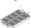
FIG. 3 is a view showing assembled parts shown inFIG. 2 ; -
FIG. 4 is a view showing a battery unit; -
FIG. 5 is an exploded-perspective view showing the battery unit shown inFIG. 4 ; -
FIG. 6 is a detailed view showing a unit busbar shown inFIGS. 4 and5 ; -
FIG. 7 is a view showing a restriction protrusion and a restriction groove provided in the battery unit; -
FIG. 8 is a view showing a pressing plate; -
FIG. 9 is a view showing a top cover; -
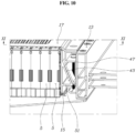
FIG. 10 is a view showing the coupled battery units pressed by the top cover and the pressing plate; -
FIG. 11 is a sectional view showing line X I - X I shown inFIG. 10 ; -
FIG. 12 is a view showing coupling the top cover to a lower tray by a plurality of pressure bolts; -
FIG. 13 is a view showing a sensing assembly; and -
FIG. 14 is a view showing a plurality of CMU connectors located at a lower portion of the sensing assembly shown inFIG. 13 . - It is understood that the term "vehicle" or "vehicular" or other similar term as used herein is inclusive of motor vehicles in general such as passenger automobiles including sports utility vehicles (SUV), buses, trucks, various commercial vehicles, watercraft including a variety of boats and ships, aircraft, and the like, and includes hybrid vehicles, electric vehicles, plug-in hybrid electric vehicles, hydrogen-powered vehicles and other alternative fuel vehicles (e.g. fuels derived from resources other than petroleum). As referred to herein, a hybrid vehicle is a vehicle that has two or more sources of power, for example both gasoline-powered and electric-powered vehicles.
- The terminology used herein is for the purpose of describing particular embodiments only and is not intended to be limiting of the disclosure. As used herein, the singular forms "a," "an" and "the" are intended to include the plural forms as well, unless the context clearly indicates otherwise. It will be further understood that the terms "comprises" and/or "comprising," when used in this specification, specify the presence of stated features, integers, steps, operations, elements, and/or components, but do not preclude the presence or addition of one or more other features, integers, steps, operations, elements, components, and/or groups thereof. As used herein, the term "and/or" includes any and all combinations of one or more of the associated listed items. Throughout the specification, unless explicitly described to the contrary, the word "comprise" and variations such as "comprises" or "comprising" will be understood to imply the inclusion of stated elements but not the exclusion of any other elements. In addition, the terms "unit", "-er", "-or", and "module" described in the specification mean units for processing at least one function and operation and can be implemented by hardware components or software components and combinations thereof.
- Further, the control logic of embodiments of the present disclosure may be embodied as non-transitory computer readable media on a computer readable medium containing executable program instructions executed by a processor, controller, or the like. Examples of computer readable media include, but are not limited to, ROM, RAM, compact disc (CD)-ROMs, magnetic tapes, floppy disks, flash drives, smart cards, and optical data storage devices. The computer readable medium can also be distributed in network coupled computer systems so that the computer readable media is stored and executed in a distributed fashion, e.g., by a telematics server or a Controller Area Network (CAN)
- In the following description, the structural or functional description specified to exemplary embodiments according to the concept of embodiments of the present disclosure is intended to describe the exemplary embodiments, so it should be understood that embodiments of the present disclosure may be variously embodied, without being limited to the exemplary embodiments.
- Embodiments described herein may be changed in various ways and various shapes, so specific embodiments are shown in the drawings and will be described in detail in this specification. However, it should be understood that the exemplary embodiments according to the concept of the embodiments of present disclosure are not limited to the embodiments which will be described hereinbelow with reference to the accompanying drawings, but all of modifications, equivalents, and substitutions are included in the scope and spirit of embodiments of the disclosure.
- It will be understood that, although the terms first and/or second, etc. may be used herein to describe various elements, these elements should not be limited by these terms. These terms are only used to distinguish one element, from another element. For instance, a first element discussed below could be termed a second element without departing from the teachings of embodiments of the present disclosure. Similarly, the second element could also be termed the first element.
- It is to be understood that when one element is referred to as being "connected to" or "coupled to" another element, it may be connected directly to or coupled directly to another element or be connected to or coupled to another element, having the other element intervening therebetween. On the other hand, it is to be understood that when one element is referred to as being "connected directly to" or "coupled directly to" another element, it may be connected to or coupled to another element without the other element intervening therebetween. Further, the terms used herein to describe a relationship between elements, that is, "between", "directly between", "adjacent" or "directly adjacent" should be interpreted in the same manner as those described above.
- The terminology used herein is for the purpose of describing particular embodiments only and is not intended to limit embodiments of the present disclosure. Singular forms are intended to include plural forms unless the context clearly indicates otherwise. It will be further understood that the terms "comprises" or "have" used in this specification, specify the presence of stated features, steps, operations, components, parts, or a combination thereof, but do not preclude the presence or addition of one or more other features, numerals, steps, operations, components, parts, or a combination thereof.
- Unless otherwise defined, all terms including technical and scientific terms used herein have the same meaning as commonly understood by those skilled in the art to which embodiments of the present disclosure belong. It must be understood that the terms defined by the dictionary are identical with the meanings within the context of the related art, and they should not be ideally or excessively formally defined unless the context clearly dictates otherwise.
- Exemplary embodiments will be described hereafter in detail with reference to the accompanying drawings. Like reference numerals given in the drawings indicate like components.
- Referring to
FIGS. 1 to 3 , according to embodiments of the present disclosure, abattery pack 1 for a vehicle may include: abattery unit 5 comprisingbattery cells 3 overlapped with each other;unit busbars 7 respectively connected to electrodes at opposite ends of thebattery cells 3 constituting thebattery unit 5, and extended upward from thebattery unit 5; unit busbar support bodies 9 located at opposite ends of thebattery unit 5 and supporting theunit busbars 7 and thebattery cells 3; alower tray 11 on whichbattery units 5 are loaded while being overlapped with each other, thelower tray 11 supporting lower surfaces and side surfaces of the overlappedbattery units 5; apressing plate 15 disposed between each ofside walls 13 of thelower tray 11 and thebattery units 5, and configured to press thebattery units 5 in an overlapped direction of thebattery units 5; and atop cover 17 forcibly coupled to the overlappedbattery units 5 in a downward direction so as to cover upper portions of the overlappedbattery units 5, and configured to supply pressure for thepressing plate 15 to press thebattery units 5. - Furthermore, a
sensing assembly 19 may be provided above thetop cover 17 to electrically connect theunit busbars 7 of thebattery units 5 loaded on thelower tray 11 to each other. Anupper casing 21 may be coupled to an upper portion of thesensing assembly 19 thus forming abattery pack 1. - For example, a
wiring 23 promoting various electric connections between theupper casing 21 and thesensing assembly 19 is presented inFIG. 1 . - Furthermore, in
FIGS. 1 and2 , 5S indicates the overlapped battery units. - As shown in
FIGS. 4 and5 , thebattery unit 5 may be configured such that twobattery cells 3 are overlapped with each other with acompressed pad 25 provided between the twobattery cells 3; and theunit busbars 7 are respectively coupled to the electrodes of the two overlappedbattery cells 3. - Each of the unit busbar support bodies 9 may include a
unit busbar housing 27 and aunit busbar cover 29. Theunit busbar housing 27 may support a gap between thebattery cells 3 and each of theunit busbars 7, and theunit busbar cover 29 may be coupled to theunit busbar housing 27 with theunit busbar 7 located between theunit busbar cover 29 and theunit busbar housing 27 and may cover an outer portion of theunit busbar 7. -
FIG. 6 is a view showing theunit busbar 7. Theunit busbar 7 may include: twoelectrode coupling portions 31 respectively coupled to the opposite electrodes of the twobattery cells 3; and an upper exposedportion 35 extended upward from thebattery unit 5 and coupled to inter-busbars 33 of thesensing assembly 19 by welding, theinter-busbars 33 of thesensing assembly 19 will be described later. - The two
battery cells 3 of thebattery unit 5 may be arranged such that electrodes with same polarity are coupled to thesame unit busbar 7, and electrodes with opposite polarities may be arranged in overlappedbattery units 5 adjacent to each other. Therefore, when theunit busbars 7 of the twobattery units 5 located adjacent to each other may be connected to each other by the inter-busbars 33, the overlappedbattery units 5 are connected to each other in series. - Each of the unit busbar support bodies 9 may include a
restriction protrusion 37 and arestriction groove 39 to restrain a relative location with respect to another overlapped unit busbar support body 9. - For example, as shown in
FIG. 7 , therestriction protrusion 37 may protrude on a first surface of thebattery unit 5 and therestriction groove 39 is formed on a position corresponding to therestriction protrusion 37 in a second surface of thebattery unit 5. Therefore, the twobattery units 5 that are overlapped adjacent to each other may be relatively constrained in positional relationship. Consequently, it is possible to stably maintain an overlapped state of the plurality ofbattery units 5 that are arranged adjacent to each other in order. - The
lower tray 11 may include acenter member 41 at a center portion thereof and theside walls 13 at side portions thereof. The plurality ofbattery units 5 ,au be loaded between thecenter member 41 and each of theside walls 13 of thelower tray 11 while being overlapped with each other. - In other words, the plurality of
battery units 5 in the overlapped state may be loaded on opposite portions of thelower tray 11 based on thecenter member 41 of thelower tray 11. - The
pressing plate 15 may be provided between the overlappedbattery units 5 loaded on thelower tray 11 and theside walls 13 of thelower tray 11, and thepressing plate 15 presses the overlappedbattery units 5 toward the sensing member. Accordingly, structural stability of the overlappedbattery units 5 may be secured and surface pressure of thebattery cells 3 constituting thebattery units 5 may be secured. - Therefore, compared to a conventional method in which a plurality of battery cells is configured as battery modules by using a separate end plate, etc., and a plurality of battery modules is arranged on the above-described lower tray, the battery pack of embodiments of the present disclosure does not require parts such as the end plate, etc., but additional battery cells may be loaded. Therefore, a larger number of battery cells are loaded on the lower tray substantially the same volume, and the energy density of the battery pack may be ultimately increased.
- As shown in
FIG. 8 , thepressing plate 15 may include a flat surface facing thebattery unit 5 and aninclined surface 43 opposite to the flat surface. Theinclined surface 43 may protrude to be gradually inclined in the downward direction. - The
pressing plate 15 may be an aluminum extrusion material and may include aninsulation film 45 on the surface of thepressing plate 15, the surface facing thebattery unit 5. - Meanwhile, as shown in
FIG. 9 , thetop cover 17 may includewedge portions 47 integrally formed on lower portions of opposite ends thereof. Each of thewedge portions 47 may press theinclined surface 43 of thepressing plate 15 while being moved downward, so that thepressing plate 15 presses the overlappedbattery units 5 toward thecenter member 41. - In other words, as shown in
FIGS. 10 and11 , as each of thewedge portions 47 may be pressed downward between thepressing plate 15 and theside walls 13 of thelower tray 11, thereby generating a pressure for thepressing plate 15 to press the overlappedbattery units 5 toward thecenter member 41. - Referring to
FIG. 11 , each of theside walls 13 of thelower tray 11 may have aninner protrusion 49 at a lower portion thereof and the inner protrusion protrudes toward the overlappedbattery units 5. Thepressing plate 15 may include aguide surface 51, and theguide surface 51 may constitute a triangle together with theinclined surface 43 and may be in surface-contact with an upper surface of theinner protrusion 49 so as to guide thepressing plate 15 when thepressing plate 15 is moved toward thebattery unit 5. - Furthermore, the battery pack may include a plurality of
pressure bolts 53 to press thewedge portions 47 of thetop cover 17 toward theinner protrusion 49 of thelower tray 11. - Meanwhile, the
inclined surface 43 and theguide surface 51 of thepressing plate 15 may include a plurality of throughholes 55 as shown inFIG. 8 . The plurality of throughholes 55 may be provided to allow movement of thepressing plate 15 while thepressure bolts 53 pass through thepressing plate 15. - Therefore, when the
pressure bolts 53 are coupled to the pressing plate, thewedge portion 47 of thetop cover 17 is pressed toward theinner protrusion 49 of thelower tray 11. As thewedge portion 47 is moved, thepressing plate 15 may press thebattery units 5 toward thecenter member 41. - The
guide surface 51 of thepressing plate 15 may be guided by the upper surface of theinner protrusion 49 of theside walls 13 of thelower tray 11, and the movement of thepressing plate 15 may be freely allowed by the throughholes 55 even with thepressure bolts 53. - For example,
FIG. 12 is a view showing coupling thewedge portions 47 of thetop cover 17 to theinner protrusion 49 of thelower tray 11 by the plurality ofpressure bolts 53. - As shown in
FIG. 13 , thesensing assembly 19 may be formed in a single flat plate integrated with a highcurrent busbar 57 connecting all thebattery units 5 loaded on thelower tray 11 to each other in series. - The high
current busbar 57 may include the plurality ofinter-busbars 33 and a plurality oflong busbars 59. The plurality ofinter-busbars 33 may be arranged in rows at predetermined intervals in the overlapped direction of thebattery units 5 so as to connect theunit busbars 7 of thebattery units 5 located adjacent to each other, and the plurality oflong busbars 59 may be arranged obliquely across the overlappedbattery units 5 so that the rows of the inter-busbars 33 are connected to each other. - The
sensing assembly 19 may include a plurality oftemperature sensors 61 to measure the temperature of thebattery units 5. - Furthermore, the
sensing assembly 19 may include a plurality ofCMU connectors 63 provided to transmit a voltage of each of thebattery cells 3 constituting thebattery units 5 and data of thetemperature sensors 61 to a cell monitoring unit (CMU) - For example,
FIG. 14 is a bottom view showing thesensing assembly 19 shown inFIG. 13 , and the plurality ofCMU connectors 63 is presented in the drawing. - Furthermore, the
sensing assembly 19 may include a flexible printed circuit board (FPCB) integrally provided. The FPCB may be connected to the inter-busbars 33, thetemperature sensors 61, and theCMU connectors 63 so as to transmit the voltage and temperature information of eachbattery unit 5 to the CMU through theCMU connectors 63. - Therefore, as described above, when the
sensing assembly 19 is coupled to the upper portion of the plurality ofbattery units 5 fixed by thetop cover 17, series electrical connection between all thebattery units 5 loaded on thebattery pack 1 may be achieved and also each of thebattery units 5 may secure a communication enabled state to the CMU through the FPCB and theCMU connectors 63. - For example, in
FIG. 13 , a fuse may be connected to location A and a power relay assembly (PRA) may be connected to location B. - The
top cover 17 may be formed with the width narrower than the length of each of thebattery units 5 so that theunit busbars 7 of thebattery units 5 are exposed upward. The highcurrent busbar 57 of thesensing assembly 19 may be weld to upper surfaces of theunit busbars 7 of thebattery units 5 exposed through opposite sides of thetop cover 17. - Therefore, when the
sensing assembly 19 is overlapped above thetop cover 17, theinter-busbars 33 of thesensing assembly 19 may be located on the upper surfaces (upper exposed portions) of theunit busbars 7 of thebattery units 5, and thesensing assembly 19 and thebattery units 5 may be easily coupled to each other by welding. - Although the preferred embodiment of the present disclosure has been disclosed for illustrative purposes, those skilled in the art will appreciate that various modifications, additions, and substitutions are possible, without departing from the spirit and scope of embodiments of the present disclosure.
Claims (15)
- A battery pack for a vehicle, the battery pack comprising:a battery unit comprising a plurality of battery cells overlapped with each other;unit busbars respectively coupled to electrodes at opposite ends of the battery cells constituting the battery unit, the unit busbars being extended upward from the battery unit;unit busbar support bodies located at opposite ends of the battery unit and supporting both the unit busbars and the battery cells;a lower tray on which battery units are loaded while being overlapped with each other, the lower tray supporting lower surfaces and side surfaces of the overlapped battery units;a pressing plate disposed between each of side walls of the lower tray and the battery units, and configured to press the battery units in an overlapped direction of the battery units; anda top cover forcibly coupled to the overlapped battery units in a downward direction so as to cover upper portions of the overlapped battery units, and configured to supply pressure for the pressing plate to press the battery units.
- The battery pack of claim 1, wherein the battery unit is configured such that two battery cells are overlapped with each other with a compressed pad provided between the two battery cells; and
wherein each of the unit busbars is coupled to the electrodes of the overlapped two battery cells. - The battery pack of claim 1 or 2, wherein each of the unit busbar support bodies comprises a unit busbar housing and a unit busbar cover, the unit busbar housing supporting a gap between the battery cells and each of the unit busbars and the unit busbar cover being coupled to the unit busbar housing with the unit busbar located between the unit busbar housing and the unit busbar cover and covering an outer portion of the unit busbar.
- The battery pack of one of claims 1-3, wherein each of the unit busbar support bodies has a restriction protrusion and a restriction groove at positions corresponding to each other so as to restrain a relative location in response to another unit busbar support body overlapped with each other.
- The battery pack of one of claims 1-4, wherein the lower tray comprises a center member at a center portion thereof and the side walls at side portions thereof; and
wherein a plurality of battery units is arranged to be overlapped with each other between the center member and each of the side walls. - The battery pack of one of claims 1-5, wherein the pressing plate has a flat surface facing the battery units and an inclined surface opposite to the flat surface, the inclined surface protruding to be gradually inclined outward in the downward direction.
- The battery pack of claim 6, wherein the top cover comprises wedge portions integrally formed on lower portions of opposite ends, the wedge portions being configured to press the inclined surface of the pressing plate while being moved downward, so that the pressing plate presses the overlapped battery units toward the center member.
- The battery pack of claim 6 or 7, wherein each of the side walls of the lower tray has an inner protrusion at a lower portion thereof, the inner protrusion protruding toward the overlapped battery units; and
wherein the pressing plate has a guide surface, the guide surface constituting a triangle together with the inclined surface and being in surface-contact with an upper surface of the inner protrusion and being configured to guide the pressing plate when the pressing plate is moved toward the battery units. - The battery pack of claim 8 in combination with claim 7, further comprising:a plurality of pressure bolts configured to press each of the wedge portions of the top cover toward the inner protrusion of the lower tray,wherein the inclined surface and the guide surface of the pressing plate respectively have a plurality of through holes, and the plurality of through holes allows the pressing plate to be moved while the plurality of pressure bolts pass through the pressing plate.
- The battery pack of one of claims 1-9, further comprising:a sensing assembly provided above the top cover, the sensing assembly being configured to electrically connect the unit busbars of the battery units loaded on the lower tray to each other,wherein the sensing assembly is formed in a single flat plate integrated with a high current busbar connecting all the battery units loaded on the lower tray to each other in series.
- The battery pack of claim 10, wherein the high current busbar comprises:a plurality of inter-busbars arranged in rows at predetermined intervals in an overlapped direction of the battery units so as to connect the unit busbars of the battery units located adj acent to each other; anda plurality of long busbars arranged obliquely across the overlapped battery units so that the rows of the inter-busbars are connected to each other.
- The battery pack of claim 10 or 11, wherein the sensing assembly comprises a plurality of temperature sensors measuring temperatures of the battery units.
- The battery pack of claim 12, wherein the sensing assembly comprises a plurality of center monitor unit (CMU) connectors configured to transmit a voltage of each of the battery cells constituting each of the battery units and data of the temperature sensors to a CMU
- The battery pack of claim 13, wherein the sensing assembly comprises a FPCB integrally provided, the FPCB is connected to the plurality of inter-busbars, the plurality of temperature sensors, and the plurality of CMU connectors so as to transmit the voltage and temperature information of each of the battery units through the CMU connectors.
- The battery pack of one of claims 10-14, wherein the top cover is formed with a width narrower than a length of each of the battery units so that the unit busbars of the battery unit are exposed upward; and
wherein the high current busbar of the sensing assembly is weld to the upper surfaces of the unit busbars of the battery units exposed through opposite sides of the top cover.
Applications Claiming Priority (1)
| Application Number | Priority Date | Filing Date | Title |
|---|---|---|---|
| KR1020210177901A KR102948189B1 (en) | 2021-12-13 | 2021-12-13 | Battery pack for vehicle |
Publications (2)
| Publication Number | Publication Date |
|---|---|
| EP4195371A2 true EP4195371A2 (en) | 2023-06-14 |
| EP4195371A3 EP4195371A3 (en) | 2023-11-29 |
Family
ID=83049951
Family Applications (1)
| Application Number | Title | Priority Date | Filing Date |
|---|---|---|---|
| EP22191713.1A Pending EP4195371A3 (en) | 2021-12-13 | 2022-08-23 | Battery pack for vehicle |
Country Status (4)
| Country | Link |
|---|---|
| US (1) | US12580266B2 (en) |
| EP (1) | EP4195371A3 (en) |
| KR (1) | KR102948189B1 (en) |
| CN (1) | CN116264328A (en) |
Cited By (2)
| Publication number | Priority date | Publication date | Assignee | Title |
|---|---|---|---|---|
| EP4175038A4 (en) * | 2021-02-05 | 2024-10-16 | LG Energy Solution, Ltd. | BATTERY PACK, MOTOR VEHICLE AND ENERGY STORAGE SYSTEM |
| EP4583296A1 (en) * | 2023-12-31 | 2025-07-09 | Eve Energy Co., Ltd. | Cells contact sheets, cells contact systems, and battery packs |
Families Citing this family (7)
| Publication number | Priority date | Publication date | Assignee | Title |
|---|---|---|---|---|
| JP7834061B2 (en) * | 2023-07-04 | 2026-03-23 | プライムプラネットエナジー&ソリューションズ株式会社 | Battery pack |
| JP7769664B2 (en) * | 2023-07-04 | 2025-11-13 | プライムプラネットエナジー&ソリューションズ株式会社 | Battery pack |
| CN116914301A (en) * | 2023-08-25 | 2023-10-20 | 厦门新能达科技有限公司 | Battery module and manufacturing method thereof, battery pack and electrical equipment |
| KR102938222B1 (en) * | 2024-06-20 | 2026-03-12 | 주식회사 카펙발레오 | Battery system assembly |
| CN119009293B (en) * | 2024-07-08 | 2025-09-19 | 孝感楚能新能源创新科技有限公司 | Long-size battery cell structure and battery pack |
| DE102024003378A1 (en) * | 2024-10-16 | 2026-04-16 | Mercedes-Benz Group AG | Cell holder, battery module and vehicle |
| KR102861625B1 (en) * | 2024-11-28 | 2025-09-18 | 주식회사 엠디엠 | Busbar PCB with sensing module |
Family Cites Families (8)
| Publication number | Priority date | Publication date | Assignee | Title |
|---|---|---|---|---|
| KR102497037B1 (en) * | 2017-12-06 | 2023-02-08 | 현대자동차주식회사 | Battery pack structure of vehicle |
| KR102670297B1 (en) | 2018-07-26 | 2024-05-30 | 주식회사 엘지에너지솔루션 | Busbar assembly |
| WO2020111665A1 (en) | 2018-11-27 | 2020-06-04 | 주식회사 아모그린텍 | Pouch type battery cartridge and pouch type battery pack comprising same |
| CN112151699B (en) * | 2019-06-28 | 2022-05-13 | 比亚迪股份有限公司 | Battery packs and vehicles |
| KR102887154B1 (en) * | 2019-12-17 | 2025-11-17 | 에스케이온 주식회사 | Bettery module |
| CN112310542B (en) * | 2019-12-27 | 2022-01-11 | 宁德时代新能源科技股份有限公司 | A connection assembly, battery module, battery pack, device and installation method |
| KR20210122412A (en) | 2020-03-31 | 2021-10-12 | 엘에스전선 주식회사 | Frame for battery module of electric vehicle |
| CN214254636U (en) | 2021-03-25 | 2021-09-21 | 濮阳职业技术学院 | A battery installation box |
-
2021
- 2021-12-13 KR KR1020210177901A patent/KR102948189B1/en active Active
-
2022
- 2022-08-22 US US17/892,513 patent/US12580266B2/en active Active
- 2022-08-23 EP EP22191713.1A patent/EP4195371A3/en active Pending
- 2022-09-09 CN CN202211100843.XA patent/CN116264328A/en active Pending
Cited By (3)
| Publication number | Priority date | Publication date | Assignee | Title |
|---|---|---|---|---|
| EP4175038A4 (en) * | 2021-02-05 | 2024-10-16 | LG Energy Solution, Ltd. | BATTERY PACK, MOTOR VEHICLE AND ENERGY STORAGE SYSTEM |
| US12620662B2 (en) | 2021-02-05 | 2026-05-05 | Lg Energy Solution, Ltd. | Battery pack, vehicle, and energy storage system |
| EP4583296A1 (en) * | 2023-12-31 | 2025-07-09 | Eve Energy Co., Ltd. | Cells contact sheets, cells contact systems, and battery packs |
Also Published As
| Publication number | Publication date |
|---|---|
| KR102948189B1 (en) | 2026-04-02 |
| KR20230089351A (en) | 2023-06-20 |
| US12580266B2 (en) | 2026-03-17 |
| US20230187759A1 (en) | 2023-06-15 |
| CN116264328A (en) | 2023-06-16 |
| EP4195371A3 (en) | 2023-11-29 |
Similar Documents
| Publication | Publication Date | Title |
|---|---|---|
| US12580266B2 (en) | Battery pack for vehicle | |
| US20210104803A1 (en) | Interconnecting member occupying less space in battery module and battery module comprising same | |
| US8691409B2 (en) | Battery module having sensing member with novel structure | |
| JP5593443B2 (en) | Battery module | |
| CN109428039B (en) | Bus bar, bus bar module, and battery pack | |
| CN105706272B (en) | Battery module equipped with sensing module with improved coupling structure | |
| US11942647B2 (en) | Harness isolation plate assembly, battery module, battery pack and device | |
| CN114424395B (en) | Batteries, Electronics and Vehicles | |
| JP7259993B2 (en) | Wiring module and power storage module | |
| US20220247042A1 (en) | Cell unit, energy storage module and method for the assembly thereof | |
| KR20210120862A (en) | Measuring assembly for measuring temperature and voltage | |
| CN118040251A (en) | Battery pack, bracket | |
| KR20200011810A (en) | Battery pack and vehicle comprising the battery pack | |
| KR102798589B1 (en) | Battery module and battery pack including the same | |
| KR102942276B1 (en) | Battery module | |
| CN221407581U (en) | Acquisition assembly, battery and power utilization device | |
| EP4421963A1 (en) | Battery pack with improved energy density through improvement in bonding of sensing wire of busbar | |
| JP2025014119A (en) | Battery pack for electric road vehicle and electric road vehicle equipped with said battery pack | |
| EP4459740A1 (en) | Battery module | |
| EP4567963A1 (en) | Battery pack for a road vehicle with electric propulsion and electrically propelled road vehicle provided with said battery pack | |
| US20250210731A1 (en) | Battery pack | |
| EP4391198A1 (en) | Battery module and battery pack including same | |
| CN118633196A (en) | Battery Module | |
| KR20200004206A (en) | Battery module | |
| KR101136807B1 (en) | Cartridge for Middle or Large-sized Battery Module |
Legal Events
| Date | Code | Title | Description |
|---|---|---|---|
| PUAI | Public reference made under article 153(3) epc to a published international application that has entered the european phase |
Free format text: ORIGINAL CODE: 0009012 |
|
| STAA | Information on the status of an ep patent application or granted ep patent |
Free format text: STATUS: THE APPLICATION HAS BEEN PUBLISHED |
|
| AK | Designated contracting states |
Kind code of ref document: A2 Designated state(s): AL AT BE BG CH CY CZ DE DK EE ES FI FR GB GR HR HU IE IS IT LI LT LU LV MC MK MT NL NO PL PT RO RS SE SI SK SM TR |
|
| P01 | Opt-out of the competence of the unified patent court (upc) registered |
Effective date: 20230614 |
|
| RIC1 | Information provided on ipc code assigned before grant |
Ipc: H01M 50/569 20210101ALI20230704BHEP Ipc: H01M 50/553 20210101ALI20230704BHEP Ipc: H01M 50/548 20210101ALI20230704BHEP Ipc: H01M 50/519 20210101ALI20230704BHEP Ipc: H01M 50/516 20210101ALI20230704BHEP Ipc: H01M 50/509 20210101ALI20230704BHEP Ipc: H01M 50/507 20210101ALI20230704BHEP Ipc: H01M 50/291 20210101ALI20230704BHEP Ipc: H01M 50/289 20210101ALI20230704BHEP Ipc: H01M 50/284 20210101ALI20230704BHEP Ipc: H01M 50/271 20210101ALI20230704BHEP Ipc: H01M 50/264 20210101ALI20230704BHEP Ipc: H01M 50/262 20210101ALI20230704BHEP Ipc: H01M 50/258 20210101ALI20230704BHEP Ipc: H01M 50/249 20210101ALI20230704BHEP Ipc: H01M 50/204 20210101ALI20230704BHEP Ipc: H01M 50/202 20210101ALI20230704BHEP Ipc: H01M 50/105 20210101AFI20230704BHEP |
|
| PUAL | Search report despatched |
Free format text: ORIGINAL CODE: 0009013 |
|
| AK | Designated contracting states |
Kind code of ref document: A3 Designated state(s): AL AT BE BG CH CY CZ DE DK EE ES FI FR GB GR HR HU IE IS IT LI LT LU LV MC MK MT NL NO PL PT RO RS SE SI SK SM TR |
|
| RIC1 | Information provided on ipc code assigned before grant |
Ipc: H01M 50/569 20210101ALI20231026BHEP Ipc: H01M 50/553 20210101ALI20231026BHEP Ipc: H01M 50/548 20210101ALI20231026BHEP Ipc: H01M 50/519 20210101ALI20231026BHEP Ipc: H01M 50/516 20210101ALI20231026BHEP Ipc: H01M 50/509 20210101ALI20231026BHEP Ipc: H01M 50/507 20210101ALI20231026BHEP Ipc: H01M 50/291 20210101ALI20231026BHEP Ipc: H01M 50/289 20210101ALI20231026BHEP Ipc: H01M 50/284 20210101ALI20231026BHEP Ipc: H01M 50/271 20210101ALI20231026BHEP Ipc: H01M 50/264 20210101ALI20231026BHEP Ipc: H01M 50/262 20210101ALI20231026BHEP Ipc: H01M 50/258 20210101ALI20231026BHEP Ipc: H01M 50/249 20210101ALI20231026BHEP Ipc: H01M 50/204 20210101ALI20231026BHEP Ipc: H01M 50/202 20210101ALI20231026BHEP Ipc: H01M 50/105 20210101AFI20231026BHEP |
|
| STAA | Information on the status of an ep patent application or granted ep patent |
Free format text: STATUS: REQUEST FOR EXAMINATION WAS MADE |
|
| 17P | Request for examination filed |
Effective date: 20240527 |
|
| RBV | Designated contracting states (corrected) |
Designated state(s): AL AT BE BG CH CY CZ DE DK EE ES FI FR GB GR HR HU IE IS IT LI LT LU LV MC MK MT NL NO PL PT RO RS SE SI SK SM TR |