EP4195001A1 - Fan and electronic device - Google Patents
Fan and electronic device Download PDFInfo
- Publication number
- EP4195001A1 EP4195001A1 EP22843100.3A EP22843100A EP4195001A1 EP 4195001 A1 EP4195001 A1 EP 4195001A1 EP 22843100 A EP22843100 A EP 22843100A EP 4195001 A1 EP4195001 A1 EP 4195001A1
- Authority
- EP
- European Patent Office
- Prior art keywords
- flow guiding
- channel
- air
- area
- fan
- Prior art date
- Legal status (The legal status is an assumption and is not a legal conclusion. Google has not performed a legal analysis and makes no representation as to the accuracy of the status listed.)
- Granted
Links
Images






Classifications
-
- F—MECHANICAL ENGINEERING; LIGHTING; HEATING; WEAPONS; BLASTING
- F04—POSITIVE - DISPLACEMENT MACHINES FOR LIQUIDS; PUMPS FOR LIQUIDS OR ELASTIC FLUIDS
- F04D—NON-POSITIVE-DISPLACEMENT PUMPS
- F04D17/00—Radial-flow pumps, e.g. centrifugal pumps; Helico-centrifugal pumps
- F04D17/08—Centrifugal pumps
- F04D17/16—Centrifugal pumps for displacing without appreciable compression
-
- G—PHYSICS
- G06—COMPUTING OR CALCULATING; COUNTING
- G06F—ELECTRIC DIGITAL DATA PROCESSING
- G06F1/00—Details not covered by groups G06F3/00 - G06F13/00 and G06F21/00
- G06F1/16—Constructional details or arrangements
- G06F1/20—Cooling means
-
- F—MECHANICAL ENGINEERING; LIGHTING; HEATING; WEAPONS; BLASTING
- F04—POSITIVE - DISPLACEMENT MACHINES FOR LIQUIDS; PUMPS FOR LIQUIDS OR ELASTIC FLUIDS
- F04D—NON-POSITIVE-DISPLACEMENT PUMPS
- F04D29/00—Details, component parts, or accessories
- F04D29/60—Mounting; Assembling; Disassembling
- F04D29/601—Mounting; Assembling; Disassembling specially adapted for elastic fluid pumps
- F04D29/602—Mounting in cavities
-
- F—MECHANICAL ENGINEERING; LIGHTING; HEATING; WEAPONS; BLASTING
- F04—POSITIVE - DISPLACEMENT MACHINES FOR LIQUIDS; PUMPS FOR LIQUIDS OR ELASTIC FLUIDS
- F04D—NON-POSITIVE-DISPLACEMENT PUMPS
- F04D29/00—Details, component parts, or accessories
- F04D29/40—Casings; Connections of working fluid
- F04D29/42—Casings; Connections of working fluid for radial or helico-centrifugal pumps
- F04D29/4206—Casings; Connections of working fluid for radial or helico-centrifugal pumps especially adapted for elastic fluid pumps
- F04D29/4213—Casings; Connections of working fluid for radial or helico-centrifugal pumps especially adapted for elastic fluid pumps suction ports
-
- F—MECHANICAL ENGINEERING; LIGHTING; HEATING; WEAPONS; BLASTING
- F04—POSITIVE - DISPLACEMENT MACHINES FOR LIQUIDS; PUMPS FOR LIQUIDS OR ELASTIC FLUIDS
- F04D—NON-POSITIVE-DISPLACEMENT PUMPS
- F04D29/00—Details, component parts, or accessories
- F04D29/40—Casings; Connections of working fluid
- F04D29/42—Casings; Connections of working fluid for radial or helico-centrifugal pumps
- F04D29/4206—Casings; Connections of working fluid for radial or helico-centrifugal pumps especially adapted for elastic fluid pumps
- F04D29/4226—Fan casings
-
- F—MECHANICAL ENGINEERING; LIGHTING; HEATING; WEAPONS; BLASTING
- F04—POSITIVE - DISPLACEMENT MACHINES FOR LIQUIDS; PUMPS FOR LIQUIDS OR ELASTIC FLUIDS
- F04D—NON-POSITIVE-DISPLACEMENT PUMPS
- F04D29/00—Details, component parts, or accessories
- F04D29/40—Casings; Connections of working fluid
- F04D29/42—Casings; Connections of working fluid for radial or helico-centrifugal pumps
- F04D29/44—Fluid-guiding means, e.g. diffusers
- F04D29/441—Fluid-guiding means, e.g. diffusers especially adapted for elastic fluid pumps
-
- F—MECHANICAL ENGINEERING; LIGHTING; HEATING; WEAPONS; BLASTING
- F04—POSITIVE - DISPLACEMENT MACHINES FOR LIQUIDS; PUMPS FOR LIQUIDS OR ELASTIC FLUIDS
- F04D—NON-POSITIVE-DISPLACEMENT PUMPS
- F04D29/00—Details, component parts, or accessories
- F04D29/60—Mounting; Assembling; Disassembling
- F04D29/62—Mounting; Assembling; Disassembling of radial or helico-centrifugal pumps
- F04D29/624—Mounting; Assembling; Disassembling of radial or helico-centrifugal pumps especially adapted for elastic fluid pumps
-
- F—MECHANICAL ENGINEERING; LIGHTING; HEATING; WEAPONS; BLASTING
- F04—POSITIVE - DISPLACEMENT MACHINES FOR LIQUIDS; PUMPS FOR LIQUIDS OR ELASTIC FLUIDS
- F04D—NON-POSITIVE-DISPLACEMENT PUMPS
- F04D29/00—Details, component parts, or accessories
- F04D29/66—Combating cavitation, whirls, noise, vibration or the like; Balancing
- F04D29/661—Combating cavitation, whirls, noise, vibration or the like; Balancing especially adapted for elastic fluid pumps
- F04D29/667—Combating cavitation, whirls, noise, vibration or the like; Balancing especially adapted for elastic fluid pumps by influencing the flow pattern, e.g. suppression of turbulence
-
- G—PHYSICS
- G06—COMPUTING OR CALCULATING; COUNTING
- G06F—ELECTRIC DIGITAL DATA PROCESSING
- G06F1/00—Details not covered by groups G06F3/00 - G06F13/00 and G06F21/00
- G06F1/16—Constructional details or arrangements
- G06F1/1613—Constructional details or arrangements for portable computers
- G06F1/1615—Constructional details or arrangements for portable computers with several enclosures having relative motions, each enclosure supporting at least one I/O or computing function
- G06F1/1616—Constructional details or arrangements for portable computers with several enclosures having relative motions, each enclosure supporting at least one I/O or computing function with folding flat displays, e.g. laptop computers or notebooks having a clamshell configuration, with body parts pivoting to an open position around an axis parallel to the plane they define in closed position
-
- G—PHYSICS
- G06—COMPUTING OR CALCULATING; COUNTING
- G06F—ELECTRIC DIGITAL DATA PROCESSING
- G06F1/00—Details not covered by groups G06F3/00 - G06F13/00 and G06F21/00
- G06F1/16—Constructional details or arrangements
- G06F1/1613—Constructional details or arrangements for portable computers
- G06F1/1633—Constructional details or arrangements of portable computers not specific to the type of enclosures covered by groups G06F1/1615 - G06F1/1626
-
- G—PHYSICS
- G06—COMPUTING OR CALCULATING; COUNTING
- G06F—ELECTRIC DIGITAL DATA PROCESSING
- G06F1/00—Details not covered by groups G06F3/00 - G06F13/00 and G06F21/00
- G06F1/16—Constructional details or arrangements
- G06F1/20—Cooling means
- G06F1/203—Cooling means for portable computers, e.g. for laptops
-
- F—MECHANICAL ENGINEERING; LIGHTING; HEATING; WEAPONS; BLASTING
- F05—INDEXING SCHEMES RELATING TO ENGINES OR PUMPS IN VARIOUS SUBCLASSES OF CLASSES F01-F04
- F05D—INDEXING SCHEME FOR ASPECTS RELATING TO NON-POSITIVE-DISPLACEMENT MACHINES OR ENGINES, GAS-TURBINES OR JET-PROPULSION PLANTS
- F05D2250/00—Geometry
- F05D2250/10—Two-dimensional
- F05D2250/14—Two-dimensional elliptical
Definitions
- This application relates to the field of heat dissipation technologies for electronic products, and in particular, to a fan and an electronic device.
- This application provides a fan and an electronic device, so as to improve a heat dissipation effect and prevent overheating of electronic components such as processors.
- this application provides a fan, including a body.
- the body includes an end cover, a bottom cover, a peripheral plate, blades, and a flow guiding member; the end cover and the bottom cover are opposite and spaced apart, two opposite sides of the peripheral plate in a thickness direction of the fan are connected to the end cover and the bottom cover respectively; the end cover, the bottom cover, and the peripheral plate form an air duct extending in a length direction of the fan, and the blades and the flow guiding member are mounted between the end cover and the bottom cover.
- the air duct includes an air inlet area and an air outlet area that are sequentially distributed and communicated in the length direction of the fan; the end cover is provided with an air inlet communicated with the air inlet area; a part between the end cover and the bottom cover is not connected by a connecting plate to form an air outlet; the air outlet area is corresponding to the air outlet and is communicated with the air outlet; and the blades are located in the air inlet area, and the flow guiding member is located in the air outlet area.
- the flow guiding member includes a first guide plate, a second guide plate, and a sleeve; the end cover, the first guide plate, the second guide plate, and the bottom cover are sequentially laminated and spaced apart in the thickness direction of the fan, so that a first channel is formed between the first guide plate and an inner wall of the air duct, the first guide plate and the second guide plate are oppositely spaced apart to form a second channel, and a third channel is formed between the second guide plate and the inner wall of the air duct; and the first channel, the second channel, and the third channel are sequentially disposed in the thickness direction of the fan.
- the sleeve is located in the first channel or the third channel, and includes a flow guiding cavity; one side that is of the second channel and that faces the air inlet area is isolated from the air inlet area, one side that is of the second channel and that faces away from the air inlet area forms a flow guiding outlet, and the flow guiding outlet and the air outlet face the same direction and are communicated.
- the air inlet area, the first channel, and the air outlet are sequentially communicated to form an air flow path, and the air inlet area, the third channel, and the air outlet are sequentially communicated to form another air flow path.
- the flow guiding inlet, the flow guiding cavity, and the second channel are sequentially communicated; and in the length direction of the fan, the second channel is also communicated with the flow guiding outlet and the air outlet, and finally the flow guiding inlet, the flow guiding cavity, the second channel, the flow guiding outlet, and the air outlet are sequentially communicated to form still another air flow path.
- the blades in the air inlet area rotate to allow outside air to enter the air inlet area from the air inlet to form a main airflow, and then the main airflow flows from the air inlet area to the air outlet area, and finally blows out through the air outlet.
- the main airflow flows to the air outlet area, because the second channel is separated from the air inlet area, the main airflow is divided into two streams to enter the first channel and the third channel respectively. Because spaces of the first channel and the third channel are smaller than a space of the air inlet area, a flow rate of the main airflow divided into two streams is increased after entering the first channel and the third channel.
- negative pressure areas are formed on two sides of the flow guiding outlet. Air pressures in the negative pressure areas are lower than an air pressure in the second channel, resulting in a differential pressure between air pressures in the negative pressure areas and the second channel. Under an action of the differential pressure, outside air is induced to enter the flow guiding cavity from the flow guiding inlet to form an induced airflow, then the induced airflow enters the second channel from the flow guiding cavity, finally flows to the air outlet through the flow guiding outlet, and then blows out from the air outlet.
- a total air output of the fan includes three parts: the main airflow, the induced airflow, and the driven airflow. Compared with a conventional component without the flow guiding member, the air output is significantly increased, and therefore, heat dissipation efficiency is improved.
- the main airflow is blocked by the sleeve when flowing through a position where the sleeve is located.
- a flow rate of the main airflow is further increased, so that the differential pressure between air pressures in the negative pressure areas and the second channel is more significant. Therefore, more air is induced to enter the flow guiding cavity to form an induced airflow with a larger air volume.
- the body includes an end cover, the end cover forms an inner wall that is of the air duct and that is corresponding to the first guide plate, the sleeve includes a first sleeve, and the first sleeve is located in the first channel, and is hermetically connected to the end cover and the first guide plate respectively along two opposite ends in the thickness direction of the fan;
- the flow guiding inlet includes a first flow guiding inlet formed on the end cover, the flow guiding cavity includes a first flow guiding cavity formed on the first sleeve, and the first flow guiding cavity is communicated with the first flow guiding inlet and the second channel.
- the first sleeve is disposed, and a flow guiding cavity of the first sleeve is referred to as the first flow guiding cavity. Then a flow rate of a part of the main airflow entering the first channel is further increased due to blocking of the first sleeve.
- the differential pressure between air pressures in the negative pressure areas and the second channel is more significant. Under an action of the differential pressure, outside air enters the first flow guiding cavity from the first flow guiding inlet to form a first induced airflow, the first induced airflow then enters the second channel from the first flow guiding cavity, and finally flows to the air outlet through the flow guiding outlet, thereby increasing the total air output of the fan.
- the first guide plate is disposed around a periphery of the first sleeve, so that the first channel surrounds the periphery of the first sleeve. Therefore, the first sleeve is located in the middle of the first channel in the length direction of the fan. In this case, the flow rate of the part of the main airflow entering the first channel is increased once due to a spatial difference between the first channel and the air inlet area, and the flow rate is increased once again under blocking of the first sleeve, so that the part of the main airflow in the first channel may be accelerated twice.
- an edge that is of the first guide plate and that faces the air inlet area is aligned with a part of an edge of the first sleeve. Therefore, the first sleeve is located at an edge that is of the first channel and that faces the air inlet area. In this case, the flow rate of the part of the main airflow entering the first channel is increased rapidly due to the spatial difference between the first channel and the air inlet area and blocking of the first sleeve.
- the sleeve includes a plurality of first sleeves
- the flow guiding inlet includes a plurality of first flow guiding inlets formed on the end cover
- the plurality of first flow guiding inlets are in a one-to-one communication with the plurality of first sleeves.
- the plurality of first sleeves and the plurality of corresponding first flow guiding inlets are disposed, so that an air volume of the first induced airflow is increased, thereby further increasing the total air output of the fan.
- the plurality of first sleeves and the plurality of first flow guiding inlets are equally spaced apart in the thickness direction of the fan. Therefore, the first induced airflow is evenly distributed, so that air outflow uniformity at the air outlet may be increased.
- the body includes a bottom cover, the bottom cover forms an inner wall that is of the air duct and that is corresponding to the second guide plate, the sleeve includes a second sleeve, and the second sleeve is located in the third channel, and is hermetically connected to the bottom cover and the second guide plate respectively along two opposite ends in the thickness direction of the fan; and the flow guiding inlet includes a second flow guiding inlet formed on the bottom cover, the flow guiding cavity includes a second flow guiding cavity formed on the second sleeve, and the second flow guiding cavity is communicated with the second flow guiding inlet and the second channel.
- the second sleeve is disposed, and a flow guiding cavity of the second sleeve is referred to as the second flow guiding cavity. Then a flow rate of a part of the main airflow entering the third channel is further increased due to blocking of the second sleeve.
- the differential pressure between air pressures in the negative pressure areas and the second channel is more significant.
- the second guide plate is disposed around a periphery of the second sleeve, so that the third channel surrounds the periphery of the second sleeve. Therefore, the second sleeve is located in the middle of the third channel in the length direction of the fan. In this case, the flow rate of the part of the main airflow entering the third channel is increased once due to a spatial difference between the third channel and the air inlet area, and the flow rate is increased once again under blocking of the second sleeve, so that the part of the main airflow in the third channel may be accelerated twice.
- the sleeve includes a plurality of second sleeves
- the flow guiding inlet includes a plurality of second flow guiding inlets formed on the bottom cover
- the plurality of second flow guiding inlets are communicated with the plurality of second sleeves in a one-to-one correspondence.
- the plurality of second sleeves and the plurality of corresponding second flow guiding inlets are disposed, so that an air volume of the second induced airflow may be increased, thereby further increasing the total air output of the fan.
- the plurality of second sleeves and the plurality of second flow guiding inlets are equally spaced apart in a width direction of the fan. Therefore, the second induced airflow is evenly distributed, so that air outflow uniformity at the air outlet may be increased.
- the flow guiding inlet and the flow guiding cavity are opposite, and have the same cross-sectional area and shape. Therefore, compared with a situation in which the flow guiding inlet and the flow guiding cavity are not aligned, the flow guiding inlet and the flow guiding cavity are aligned, so that a resistance to an induced airflow may be reduced, thereby reducing losses of the induced airflow, and ensuring that almost all of the induced airflow enters the second channel.
- widths of the first guide plate, the second guide plate, and the air outlet area are the same. Therefore, the first guide plate, the second baffle, the end cover, and the bottom cover are flush at the air outlet, so as to facilitate machining.
- the air outlet area includes a mounting area and a guide area
- the mounting area is corresponding to the air inlet area and is communicated with the air inlet area
- the guide area is corresponding to the air outlet and is communicated with the air outlet
- the flow guiding member is mounted in the mounting area, and in the length direction of the fan, widths of the first guide plate, the second guide plate, and the mounting area are the same. Therefore, the first guide plate and the second guide plate are retracted with respect to the air outlet to be hidden in the air duct, so as to reduce a weight of the fan, prevent the first guide plate and the second guide plate from shielding the guide area, guide an airflow in the guide area, and provide a surface with a Coanda effect.
- the body includes an end cover and a bottom cover that are opposite and spaced apart, the end cover includes a first guide surface facing the air duct, and a first convex portion is formed in the middle of a part that is of the first guide surface and that faces the guide area; and the bottom cover includes a second guide surface facing the air duct, a second convex portion is formed in the middle of a part that is of the second guide surface and that faces the guide area, and the first convex portion and the second convex portion protrude toward each other. Therefore, the first guide surface and the second guide surface become curved surfaces with a Coanda effect, and the surfaces with the Coanda effect enable an airflow to flow more smoothly, thereby reducing turbulence at the air outlet and reducing air volume losses.
- the sleeve includes an inner wall surface facing the flow guiding cavity, and an outer wall surface facing away from the inner wall surface, and the outer wall surface is streamlined.
- the streamlined outer wall surface has a small resistance to an airflow, and when the airflow flows through the outer wall surface, air volume losses are small.
- the flow guiding member further includes a connecting plate, two opposite sides of the connecting plate in the thickness direction of the fan are respectively connected to the first guide plate and the second guide plate, the connecting plate separates the second channel from the air inlet area, and sides that are of the first guide plate and the second guide plate and that face away from the connecting plate face the air outlet area and form the flow guiding outlet.
- the connecting plate connects sides that are of the first guide plate and the second guide plate and that face the air inlet area, thereby isolating the second channel from the air inlet area, and preventing the main airflow in the air inlet area from flowing into the second channel.
- the connecting plate is an arc-shaped sheet.
- the connecting plate is arc-shaped, so that a resistance to an airflow may be reduced, and losses of the airflow flowing through the connecting plate may be reduced.
- the connecting plate is a rectangular sheet.
- the air duct further includes a conveying area, and the conveying area is located between the air inlet area and the air outlet area, and is communicated with the air inlet area and the air outlet area respectively.
- the conveying area separates the air inlet area from the air outlet area, so that the blades located in the air inlet area are separated from the flow guiding member located in the air outlet area to prevent the blades from interfering with the flow guiding member when rotating.
- the body includes an end cover, a bottom cover, and a peripheral plate, the end cover and the bottom cover are opposite and spaced apart, two opposite sides of the peripheral plate in the thickness direction of the fan are connected to the end cover and the bottom cover respectively, the end cover, the bottom cover, and the peripheral plate form the air duct, the end cover and the bottom cover form the air outlet, and the flow guiding inlet is formed on the end cover and/or the bottom cover; and the flow guiding member is mounted between the end cover and the bottom cover. Therefore, the body has a simple structure, is easy to machine, and require low costs.
- the bottom cover, the peripheral plate, and the flow guiding member are integrally formed into a base, and the end cover is detachably connected to the peripheral plate;
- the sleeve includes a first sleeve, the first sleeve is located in the first channel and includes an end wall surface facing the end cover, and the end wall surface is hermetically bonded to the end cover. Therefore, machining is easy, and the end cover can be easily removed to overhaul components such as the blades.
- the end wall surface is bonded to the end cover to prevent the flow guiding cavity from being communicated with the first channel or the third channel, and prevent the main airflow from entering the second channel.
- an embodiment of this application provides an electronic device, including a housing and a heat sink, where the housing includes an accommodating cavity, and an air vent and a thermovent that are communicated with the accommodating cavity, the heat sink is mounted in the accommodating cavity, the heat sink includes the fan according to the first aspect of this embodiment of this application, the air inlet of the fan faces the air vent, and the air outlet of the fan faces the thermovent.
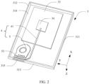
- FIG. 1 is a schematic diagram of a structure of an electronic device according to an embodiment of this application in a state; and FIG. 2 is a schematic diagram of a structure of a housing of the electronic device shown in FIG. 1 in an open state.
- An embodiment of this application provides an electronic device 1000, and the electronic device 1000 is an electronic product such as a game console, a notebook computer, a personal digital assistant, a learning machine, and a tablet computer. In this embodiment, that the electronic device 1000 is a notebook computer is used as an example for description.
- a length direction of the electronic device 1000 is defined as an X-axis direction
- a width direction of the electronic device 1000 is defined as a Y-axis direction
- a thickness direction of the electronic device 1000 is defined as a Z-axis direction.
- the X-axis direction, the Y-axis direction, and the Z-axis direction are perpendicular to each other.
- the electronic device 1000 includes a display 1, a rotating shaft member 2, and a main body 3.
- the display 1 is connected to the main body 3 by using the rotating shaft member 2, and the display 1 may be unfolded or folded with respect to the main body 3.
- the display 1 is at an angle to the main body 3, and the electronic device 1000 may be used by a user; and when the display 1 is folded with respect to the main body 3, the electronic device 1000 is in a standby state or shutdown state for easy storage.
- the display 1 includes a display surface 11 and an appearance surface 12 that face away from each other.
- the display surface 11 is attached to the main body 3, and the appearance surface 12 is exposed to be in a visible state; and when the display 1 is unfolded with respect to the main body 3, the display surface 11 is in a visible state for observation and operation by the user.
- the rotating shaft member 2 is a hinge connected between the display 1 and the main body 3.
- the rotating shaft member 2 is a rotating structure between the display 1 and the main body 3 to implement free rotation of the display 1 with respect to the main body 3.
- the main body 3 includes a housing 31, a keyboard 32, electronic components (not marked in the figure), and a heat sink 4.
- the keyboard 32 is mounted on the housing 31, and the keyboard 32 is exposed with respect to the housing 31 for the user to operate the keyboard 32.
- the electronic components and the heat sink 4 are mounted inside the housing 31.
- the electronic components include a circuit board 33, a processor 34, a memory bank, a video card, and the like.
- the processor 34, the memory bank, and the video card are integrated on the circuit board 33.
- the keyboard 32 is electrically connected to the processor 34, the user may operate the keyboard 32 to generate an operation signal, and the processor 34 may process the operation signal.
- the heat sink 4 is connected to the electronic components, and the heat sink 4 dissipates heat generated during operation of the electronic components, especially obvious heat generated when the processor 34 and the video card are operating. After heat dissipation, the heat sink 4 can prevent the electronic components from failure due to overheating.
- the housing 31 is cuboid, including a mounting wall 311, a bottom wall 312, a peripheral wall 313, a mounting cavity 314, a thermovent 315, and an air vent.
- the mounting wall 311 and the bottom wall 312 are disposed facing away from each other, and are respectively located on opposite sides of the peripheral wall 313.
- the mounting wall 311 is configured to mount the keyboard 32. When the display 1 is folded with respect to the main body 3, the mounting wall 311 is attached to the display 1 to shield and protect the keyboard 32; and when the display 1 is unfolded with respect to the main body 3, the mounting wall 311 is exposed to expose the keyboard 32 for the user to operate.
- the bottom wall 312 may be in contact with a desktop to support the electronic device 1000.
- the mounting wall 311, the bottom wall 312, and the peripheral wall 313 form a mounting cavity 314, and the mounting cavity 314 is configured to accommodate the electronic components and the heat sink 4.
- the thermovent 315 is disposed on the peripheral wall 313, and is configured to be communicated with the outside and the mounting cavity 314, so that heat from the electronic components can flow to the outside through the thermovent 315.
- the air vent is disposed on the bottom wall 312, and is configured to be communicated with the outside and the mounting cavity 314, so that outside air can enter the mounting cavity 314 for the fan 5 of the heat sink 4 to operate.
- the heat sink 4 is mounted in the mounting cavity 314 of the housing 31, and includes a heat pipe 41, a heat dissipation soldering iron (not shown in the figure), and the fan 5.
- the heat pipe 41 is a copper pipe, and the heat dissipation soldering iron is laminated on the electronic components.
- One end of the heat pipe 41 is laminated on the heat dissipation soldering iron, and the other end is provided with fins, the fins are located at the air outlet 53 of the fan 5, and the air outlet 53 of the fan 5 faces the thermovent 315 of the housing 31.
- the heat pipe 41 conducts heat from the electronic components to the fins, and the fan 5 supplies an air volume to the fins to dissipate the heat from the fins, so as to transfer the heat from the electronic components to the outside through the thermovent 315.
- FIG. 3 is a schematic diagram of a structure of the fan shown in FIG. 2
- FIG. 4 is a schematic diagram of a structure of an end cover of the fan shown in FIG. 3
- FIG. 5 is a schematic diagram of a structure of a base of the fan shown in FIG. 3 .
- the fan 5 is mounted in the mounting cavity 314.
- the fan 5 includes an air duct 51, an air inlet 52, an air outlet 53, blades 54, and a body 55.
- the air inlet 52, the air outlet 53, and the air duct 51 are all mounted on the body 55, and the blades 54 are mounted in the air duct 51.
- the air inlet 52 is configured to be communicated with the mounting cavity 314 of the housing 31 and one side of the air duct 51
- the air outlet 53 is configured to be communicated with the mounting cavity 314 of the housing 31 and the other side of the air duct 51.
- An airflow enters the air duct 51 through the air inlet 52 and flows out from the air outlet 53.
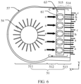
- FIG. 6 is a schematic diagram showing an airflow direction of the fan shown in FIG. 3 .
- the fan 5 When the notebook computer is operating, the fan 5 is operating. In this case, the blades 54 of the fan 5 rotate to allow outside air to enter the air duct 51 through the air vent of the housing 31 and the air inlet 52 of the fan 5.
- the air entering the air duct 51 forms a main airflow a, and then flows out from the air outlet 53 and blows to the fins, so that heat from the fins can be dissipated through the thermovent 315 of the housing 31.
- the body 55 includes an end cover 56 and a base 57
- the base 57 includes a bottom cover 58 and a peripheral plate 59
- the end cover 56 is detachably fastened to the base 57.
- the end cover 56 and the bottom cover 58 are oppositely disposed, and are respectively located on opposite sides of the peripheral plate 59 in the Z-axis direction.
- the end cover 56 is detachably fastened to the peripheral plate 59, and the end cover 56, the bottom cover 58, and the peripheral plate 59 form the air duct 51.
- the end cover 56 is opposite to the bottom wall 312 of the housing 31, and the air inlet 52 is disposed on the end cover 56, so that the air inlet 52 can be opposite to the air vent, thereby improving air intake efficiency.
- the peripheral plate 59 is opposite to the peripheral wall 313 of the housing 31, and the air outlet 53 is disposed on the peripheral plate 59, so that the air outlet 53 can be opposite to the thermovent 315, thereby improving heat dissipation efficiency.
- the end cover 56 and the base 57 are integrally formed to strengthen a structural strength of the body 55.
- the air duct 51 includes an air inlet area 511, a conveying area 512, and an air outlet area 513 that are distributed in the X-axis direction (air outlet direction) and sequentially communicated.
- the air inlet area 511 is communicated with the air inlet 52
- the air outlet area 513 is communicated with the air outlet 53.
- the blades 54 are mounted on the bottom cover 58, and are located in the air inlet area 511 of the air duct 51; and the conveying area 512 is located between the air inlet area 511 and the air outlet area 513 to prevent the blades 54 from touching a component mounted in the air outlet area 513 when rotating.
- the blades 54 of the fan 5 rotate to allow air to enter the air inlet area 511 of the air duct 51 from the air inlet 52 of the fan 5.
- the main airflow a formed by the air entering the air inlet area 511 flows through the conveying area 512 to the air outlet area 513, and then flows out from the air outlet 53 and blows to the fins, so that heat from the fins can be dissipated through the thermovent 315 of the housing 31.
- the air duct 51 includes an air inlet area and an air outlet area, and no conveying area is provided. Therefore, a size of the air duct 51 in the X-axis direction may be reduced, thereby reducing a volume of the entire fan to save space.
- the air inlet 52 in this embodiment is circular, and is corresponding to and communicated with the air inlet area 511.
- the air inlet 52 is corresponding to the air vent of the housing 31 and is communicated with the air vent of the housing 31, and the air inlet 52 allows outside air to enter the air duct 51 through the air vent of the housing 31.
- the air inlet 52 is square, elliptical, trapezoidal, triangular, or the like, which may be set specifically based on a shape and a size of the end cover 56.
- the air outlet 53 is rectangular, and is corresponding to and communicated with the air outlet area 513.
- the air outlet 53 is corresponding to and communicated with the thermovent 315 of the housing 31, and the air outlet 53 allows the main airflow formed through rotation of the blades 54 to blow to the fins, and is finally dissipated from the thermovent 315.
- the air outlet 53 is trapezoidal, elliptical, or the like, which may be set specifically based on a shape and a size of the peripheral plate 59.
- the blades 54 are made of a plastic to reduce a weight of the heat sink 4.
- the blades 54 are mounted on the bottom cover 58, and are located in the air inlet area 511. At least a part of the blades 54 is exposed with respect to the air inlet 52.
- the blades 54 may be driven by a motor to rotate, so that the air entering the air duct 51 forms the main airflow.
- the plurality of blades 54 are fastened to a rotating shaft disposed on the bottom cover 58, and the rotating shaft rotates to drive the blades 54 to rotate, so that the blades 54 drive air to form the main airflow.
- FIG. 7 is a schematic diagram of a partially internal structure of the fan shown in FIG. 3 .
- the body 55 further includes a flow guiding member 6.
- the air outlet area 513 includes a mounting area 515 and a guide area 514 that are distributed in the X-axis direction, the mounting area 515 faces the conveying area 512, and the guide area 514 faces the air outlet 53.
- the flow guiding member 6 is mounted in the mounting area 515 of the air duct 51, and is fixedly connected to the bottom cover 58. Because the conveying area 512 is located between the mounting area 515 and the air inlet area 511, the blades 54 in the air inlet area 511 may be prevented from touching the flow guiding member 6 to increase a safety coefficient.
- the bottom cover 58, the peripheral plate 59 and the flow guiding member 6 are integrally formed into a base 57, and the end cover 56 and the base 57 are detachably fastened by using a buckle and/or a screw, so that the end cover 56 may be separated from the base 57 to expose the mounting cavity 314 for cleaning, maintaining, or replacing the blades 54.
- the bottom cover 58, the peripheral plate 59, and the flow guiding member 6 are separately formed, and then fixedly connected through welding.
- the end cover 56 is a sheet, and includes a first flow guiding inlet 561, a first guide surface 562, a first appearance surface 563, and a first peripheral wall surface 564.
- the first flow guiding inlet 561 penetrates through the first guide surface 562 and the first appearance surface 563, and is configured to correspond to the air outlet area 513 of the air duct 51.
- the first guide surface 562 is disposed away from the first appearance surface 563 in the Z-axis direction, and the first peripheral wall surface 564 is connected between the first guide surface 562 and the first appearance surface 563.
- the first guide surface 562 faces the air duct, and when the fan 5 is not mounted in the mounting cavity 314, the first appearance surface 563 is located outside and is in a visible state.
- At least a part of the first peripheral wall surface 564 is located at the air outlet, and is configured to form the air outlet 53 with the base 57.
- the first flow guiding inlet 561 is circular, elliptical, square, triangular, or the like, which is not limited in this application.
- FIG. 8 is a sectional view taken along an A-A direction in FIG. 3 ;
- FIG. 9 is a sectional view taken along a B-B direction in FIG. 3 ;
- FIG. 10 is a sectional view taken along a C-C direction in FIG. 6 ; and with reference to FIG. 5 , the bottom cover 58 of the base 57 is a sheet, and the bottom cover 58 includes a second flow guiding inlet 581, a second guide surface 582, a second appearance surface 583, and a second peripheral wall surface 584.
- the second flow guiding inlet 581 penetrates through the second guide surface 582 and the second appearance surface 583, and is configured to correspond to the air outlet area 513 of the air duct 51; and the second flow guiding inlet 581 is streamlined, and the second flow guiding inlet 581 is configured to be communicated with the interior of the flow guiding member 6, so that air enters the interior of the flow guiding member 6 along the second flow guiding inlet 581 to form a second induced airflow, so as to increase the total air output.
- the second guide surface 582 is disposed away from the second appearance surface 583, and the second peripheral wall surface 584 is connected between the second guide surface 582 and the second appearance surface 583.
- the second guide surface 582 faces the air duct, and when the fan is not mounted in the mounting cavity 314, the second appearance surface 583 is located outside and is in a visible state. At least a part of the second peripheral wall surface 584 is located at the air outlet, and is configured to form the air outlet 53 with the end cover 56.
- the second flow guiding inlet 581 is circular, elliptical, square, triangular, or the like, which is not limited in this application.
- first flow guiding inlet 561 and the second flow guiding inlet 581 are the same, and the end cover 56 and the bottom cover 58 are laminated.
- first flow guiding inlet 561 and the second flow guiding inlet 581 are oppositely communicated, and air volumes of the first induced airflow b1 and a second induced airflow b2 generated by the first flow guiding inlet 561 and the second flow guiding inlet 581 are basically the same.
- the first induced airflow b1 flows from top down and the second induced airflow b2 flows from bottom up
- the air volumes of the first induced airflow b1 and the second induced airflow b2 are basically the same, most of the air volumes of the first induced airflow b1 and the second induced airflow b2 are mixed to form an induced airflow b, so as to reduce losses of the first induced airflow b1 flowing out of the second flow guiding inlet 581 and losses of the second induced airflow b2 flowing out of the first flow guiding inlet 561.
- the peripheral plate 59 is a sheet, and is located between the end cover 56 and the bottom cover 58.
- the peripheral plate 59 does not shield parts of the first peripheral wall surface 564 and the second peripheral wall surface 584 to form the air outlet 53 of the air duct 51 together with the end cover 56 and the bottom cover 58.
- the parts of first peripheral wall surface 564 and the second peripheral wall surface 584 are located on two sides of the air outlet 53 in the Z-axis direction.
- the flow guiding member 6 includes a first guide plate 63, a second guide plate 64, and a sleeve, a first channel is formed between the first guide plate 63 and an inner wall of the air duct 51, the first guide plate 63 and the second guide plate 64 are oppositely spaced apart to form a second channel, and a third channel is formed between the second guide plate 64 and the inner wall of the air duct 51; the first channel, the second channel, and the third channel are sequentially disposed in the thickness direction of the fan; and the sleeve is disposed in the first channel and/or the third channel, and the sleeve includes a flow guiding cavity.
- One side that is of the second channel and that faces the air inlet area 511 is isolated from the air inlet area 511, and one side that is of the second channel and that faces away from the air inlet area 511 forms a flow guiding outlet, and the flow guiding outlet and the air outlet face the same direction and are communicated.
- the air inlet area 511, the first channel, and the air outlet are sequentially communicated, and the air inlet area 511, the third channel, and the air outlet are sequentially communicated; and in the thickness direction of the fan, the flow guiding inlet, the flow guiding cavity, and the second channel are sequentially communicated.
- the sleeve includes a first sleeve and/or a second sleeve, a flow guiding cavity of the first sleeve is a first flow guiding cavity, a flow guiding cavity of the second sleeve is a second flow guiding cavity, and the flow guiding inlet includes a first flow guiding inlet and/or a second flow guiding inlet.
- the air inlet area 511, the first channel, and the air outlet are sequentially communicated in the length direction of the fan to form a main airflow path, and the air inlet area 511, the third channel, the air outlet are sequentially communicated in the length direction of the fan to form another main airflow path, and the two main airflow paths are configured to circulate main airflows from rotation of the blades.
- the first guide plate 63 and/or the second guide plate 64 are provided with a connecting hole corresponding to the flow guiding cavity of the sleeve, and the connecting hole is communicated with the flow guiding cavity and the second channel.
- the flow guiding inlet, the flow guiding cavity and the connecting hole are aligned and communicated in the thickness direction of the fan to form an induced airflow channel, and the induced airflow channel is configured to circulate induced airflows.
- the flow guiding member 6 is mounted in the mounting area 515 of the air outlet area 513 of the air duct 51.
- the flow guiding member 6 includes a first sleeve 61, a second sleeve 62, a first guide plate 63, a second guide plate 64, and a connecting plate 65; and the first sleeve 61, the first guide plate 63, the connecting plate 65, the second guide plate 64, and the second sleeve 62 are sequentially connected in the Z-axis direction.
- first guide plate 63 and the second guide plate 64 surround peripheries of the first sleeve 61 and the second sleeve 62, respectively, the first guide plate 63 and the second guide plate 64 are oppositely spaced, and the connecting plate 65 is connected between the first guide plate 63 and the second guide plate 64; and the first sleeve 61 is connected to the end cover 56, and the second sleeve 62 is connected to the bottom cover 58.
- the flow guiding member 6 is communicated with the first flow guiding inlet 561 and the second flow guiding inlet 581.
- a first channel L1 is formed between the first guide plate 63 and the end cover 56 in the Z-axis direction.
- the first channel L1 surrounds a periphery of the first sleeve 61 and is communicated with the conveying area 512 and the air outlet 53.
- a second channel L2 is formed among the first guide plate 63, the second guide plate 64 and the connecting plate 65, and a flow guiding outlet 66 is formed on one side opposite to the air outlet 53.
- the flow guiding outlet 66 faces the air outlet 53, so that the second channel L2 is communicated with the air outlet 53.
- the second channel L2 is isolated from the conveying area 512 by using the connecting plate 65.
- a third channel L3 is formed between the second guide plate 64 and the bottom cover 58.
- the third channel L3 surrounds a periphery of the second sleeve 62, and the third channel L3 is communicated with the conveying area 512 and the air outlet 53.
- the second channel L2 is located between the first channel L1 and the third channel L3.
- the first flow guiding inlet 561 and the second flow guiding inlet 581 are connected to the second channel L2 by using the first sleeve 61 and the second sleeve 62 respectively.
- first sleeve 61 in the Z-axis direction two sides are hermetically connected to the end cover 56 and the first guide plate 63 respectively.
- the first sleeve 61 is provided with a first flow guiding cavity 614 running in the Z-axis direction, and the first flow guiding cavity 614 is communicated with both the first flow guiding inlet and the second channel L2.
- Two sides of the second sleeve 62 in the Z-axis direction are hermetically connected to the second guide plate 64 and the bottom cover 58 respectively.
- the second sleeve 62 is provided with a second flow guiding cavity 623 running in the Z-axis direction, and the second flow guiding cavity 623 is communicated with both the second flow guiding inlet and the second channel L2.
- the first sleeve 61 is cylindrical, and includes a first inner wall surface 611, a first outer wall surface 612, and an end wall surface 613.
- the first inner wall surface 611 faces the first flow guiding cavity 614
- the first outer wall surface 612 faces away from the first inner wall surface 611
- two sides of the end wall surface 613 are connected to the first inner wall surface 611 and the first outer wall surface 612 respectively.
- the end wall surface 613 faces the end cover 56, and is hermetically connected to one surface of the end cover 56, and sides that are of the first inner wall surface 611 and the first outer wall surface 612 and that are away from the end wall surface 613 are hermetically connected to the first guide plate 63.
- An adhesive is applied in an area that is of the first guide surface 562 of the end cover 56 and that is corresponding to the end wall surface 613, or applied on the end wall surface 613.
- the adhesive fixedly adheres the first guide surface 562 and the end wall surface 613, so as to hermetically connect the end wall surface 613 and the end cover 56.
- the flow guiding member 6 is integrally formed, so that sides that are of the first inner wall surface 611 and the first outer wall surface 612 and that are away from the end wall surface 613 can be hermetically connected to the first guide plate 63.
- the second sleeve 62 is cylindrical, and includes a second inner wall surface 621, a second outer wall surface 622, and a second flow guiding cavity 623.
- the second inner wall surface 621 faces the second flow guiding cavity 623
- the second outer wall surface 622 faces away from the second inner wall surface 621
- sides that are of the first inner wall surface 611 and the second outer wall surface 622 in the Z-axis direction are hermetically connected to the second guide plate 64 respectively
- the other sides are respectively connected to the bottom cover 58.
- the flow guiding member 6 and the bottom cover are integrally formed, so that the first inner wall surface 611 and the second inner wall surface 621 are hermetically connected to the second guide plate 64 and the bottom cover 58.
- the first guide plate 63 is disposed around the periphery of the first sleeve 61, and includes a first surface 631 and a second surface 632 that face away from each other in the Z-axis direction, and the first surface 631 is connected to the first outer wall surface 612; and the first guide surface 562 and the first surface 631 form the first channel L1.
- the second guide plate 64 and the first guide plate 63 are oppositely spaced, and the second channel L2 is formed between the first guide plate 63 and the second guide plate 64.
- the second guide plate 64 is disposed around the periphery of the second sleeve 62, and includes a third surface 641 and a fourth surface 642 that face away from each other in the Z-axis direction.
- the third surface 641 is connected to the second outer wall surface 622, and the fourth surface 642 and the second guide surface 582 form the third channel L3; the second surface 632 and the third surface 641 face the second channel L2, and one side that is of the first sleeve 61 and that is connected to the first guide plate 63 and one end face that is of the second sleeve 62 and that is connected to the second guide plate 64 face the second channel L2.
- sectional areas and shapes of the first flow guiding cavity 614, the second flow guiding cavity 623, the first flow guiding inlet 561, and the second flow guiding inlet 581 are the same, that is, projections of the first flow guiding cavity 614, the second flow guiding cavity 623, the first flow guiding inlet 561, and the second flow guiding inlet 581 in the direction perpendicular to the Z axis coincide, so as to facilitate machining, and ensure that airflows can smoothly circulate to the first flow guiding cavity 614 and the second flow guiding cavity 623 after entering the first flow guiding inlet 561 and the second flow guiding inlet 581, thereby increasing an air volume of an induced airflow, and preventing airflow damage due to misalignment of the cavities and the inlets.
- the connecting plate 65 is connected between the first guide plate 63 and the second guide plate 64.
- two sides of the connecting plate 65 in the Z-axis direction are respectively connected to sides that are of the first guide plate 63 and the second guide plate 64 and that face the conveying area 512, so as to isolate the second channel L2 from the conveying area 512, and prevent an airflow from the conveying area 512 from flowing into the second channel L2; sides that are of the first guide plate 63 and the second guide plate 64 and that face the air outlet 53 are spaced apart to form the flow guiding outlet 66, and the flow guiding outlet 66 faces the air outlet 53, so that the second channel L2 is communicated with the air outlet 53.
- the connecting plate 65 is a rectangular sheet to facilitate machining. Referring to FIG. 7, FIG. 8 , and FIG. 10 , the connecting plate 65 extends to seal two opposite sides of the first guide plate 63 and the second guide plate 64 along a Y axis.
- the second channel L2 has a structure with three sides closed and one side open, and the open side is the flow guiding outlet 66.
- the connecting plate 65 seals only one side that is of the first channel L1 and that faces the conveying area 512, and the other three sides of the second channel L2 are open. In this case, a weight of the connecting plate 65 is reduced, which facilitates a lightweight design of the entire fan.
- FIG. 12 FIG.
- the connecting plate 65 is an arc-shaped sheet.
- one side that is of the connecting plate 65 and that faces away from the second channel L2 has a low resistance to a main airflow that flows through, so as to reduce losses of the main airflow.
- One side that is of the connecting plate 65 and that faces the second channel L2 has a low resistance to an induced airflow, so as to reduce losses of the induced airflow.
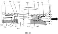
- FIG. 11 is a schematic diagram showing an airflow in the schematic diagram of the internal structure shown in FIG. 7 .
- a main airflow a formed through rotation of the blades 54 flows in a direction from the air duct 51 to the air outlet 53.
- the main airflow a will bypass the connecting plate 65 due to blocking of the connecting plate 65, and then flow into the first channel L1 and the third channel L3. Due to blocking of the connecting plate 65, a volume of an available space for the main airflow a is reduced suddenly, and a flow rate of the main airflow a is increased.
- a part of the main airflow a entering the first channel L1 is blocked by the first outer wall surface 612 of the first sleeve 61, so that the volume of the available space is further reduced, and the flow rate is further increased.
- a negative pressure area M will be formed near the flow guiding outlet 66.
- a differential pressure exists between air pressures in the negative pressure area M and the first flow guiding cavity 614. Under an action of the differential pressure, induced air enters the first flow guiding cavity 614 from the first flow guiding inlet 561, thereby forming the first induced airflow b1.
- a part of the main airflow a entering the third channel L3 is blocked by the second outer wall surface 622 of the second sleeve 62, so that the volume of the available space is further reduced, and the flow rate is further increased.
- a negative pressure area M will be formed near the flow guiding outlet 66.
- a differential pressure exists between air pressures in the negative pressure area M and the second flow guiding cavity 623.
- induced air enters the second flow guiding cavity 623 from the second flow guiding inlet 581, thereby forming the second induced airflow b2; and after the first induced airflow b1 and the second induced airflow b2 are mixed in the second channel L2 into an induced airflow b, the induced airflow b flows to the air outlet 53 of the fan 5 along the flow guiding outlet 66.
- the main airflow a finally flows to the air outlet 53 after bypassing the first sleeve 61 and the second sleeve 62, the main airflow a will rub against the first peripheral wall surface 564 and the second peripheral wall surface 584 that are located on two sides of the air outlet 53.
- an air output of the fan 5 includes three parts: the main airflow a, the induced airflow b, and the driven airflow c. Compared with a conventional component without the flow guiding member 6, the air output is significantly increased, and therefore, heat dissipation efficiency is improved.
- the flow guiding member 6 in the X-axis direction, is mounted in the mounting area 515, and the guide area 514 is formed between the mounting area 515 and the air outlet 53.
- the first guide plate 63 and the second guide plate 64 are retracted with respect to the air outlet to be hidden in the air duct 51. Therefore, the main airflow a flows out of the first channel L1 and the third channel L3, and then needs to pass through the guide area 514 before reaching the air outlet 53; and the induced airflow b flows out of the second channel L2, and then also needs to pass through the guide area 514 before reaching the air outlet 53.
- the guide area 514 may guide the induced airflow b and the main airflow a to make the airflows directional, and the directional airflows can slow down losses of airflow rates and increase an air output.
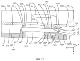
- a first convex portion 5624 is formed in the middle of a part that is of the first guide surface 562 and that faces the guide area 514, so that the first guide surface 562 is a surface with a Coanda effect.
- a part that is of the first guide surface 562 and that faces the air outlet area 513 includes a first plane section 5621, a first transition section 5622, and a first cambered section 5623 that are sequentially connected.
- the first transition section 5622 smoothly connects the first plane section 5621 and the first cambered section 5623, so that the first guide surface 562 is smoother.
- the first plane section 5621 and the first transition section 5622 face the first channel L1, and the first cambered section 5623 faces the guide area 514.
- the first cambered section 5623 gradually inclines toward a direction close to the bottom cover 58, and then gradually inclines toward a direction away from the bottom cover 58, so that the first convex portion 5624 is formed in the middle of the first guide surface 562 in the X-axis direction, and the first convex portion 5624 extends in the Y-axis direction (thickness direction).
- the middle is any position between two sides of the first cambered section 5623 in the X-axis direction.
- a second convex portion 5824 is formed in the middle of a part that is of the second guide surface 582 and that faces the guide area 514, so that the second guide surface 582 is a surface with a Coanda effect.
- the second guide surface 582 includes a second plane section 5821, a second transition section 5822, and a second cambered section 5823 that are sequentially connected.
- the second transition section 5822 smoothly connects the second plane section 5821 and the second cambered section 5823, so that the second guide surface 582 is smoother.
- the second plane section 5821 and the second transition section 5822 face the second channel L2, and the second cambered section 5823 faces the guide area 514.
- the second cambered section 5823 gradually inclines toward a direction close to the end cover 56, and then gradually inclines toward a direction away from the end cover 56, so that the second convex portion 5824 is formed in the middle of the second guide surface 582 in the X-axis direction, and the second convex portion 5824 extends in the Y-axis direction.
- the middle is any position between two sides of the second cambered section in the X-axis direction.
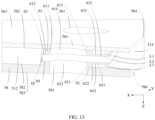
- FIG. 13 is a schematic diagram of a partially internal structure according to still another implementation of the fan shown in FIG. 3 .
- a difference from that shown in FIG. 7 is that both the first guide surface 562 and the second guide surface 582 are flat for easy machining.
- FIG. 14 is a schematic diagram of a partially internal structure according to yet another implementation of the fan shown in FIG. 3 .
- the flow guiding member 6 is mounted in the air outlet area, and a size of the flow guiding member 6 in the X-axis direction is the same as that of the air outlet area.
- the first guide plate 63 and the second guide plate 64 are flush with the air outlet 53.
- the first guide plate 63 and the second guide plate 64 each have one side and the other side that are disposed facing away from each other in the X-axis direction.
- one side of the first guide plate 63 and one side of the second guide plate 64 are aligned with one side that is of the air outlet area 513 and that faces the conveying area 512, and the other side of the first guide plate 63 and the other side of the second guide plate 64 are aligned with the air outlet 53 to facilitate machining.
- the first outer wall surface 612 of the first sleeve 61 is arc-shaped, so that the first outer wall surface 612 has a low resistance to a part of the main airflow a flowing in the first channel L1 to ensure that the main airflow a entering the first channel L1 has a high flow rate.
- a difference between air pressures in the negative pressure area M and the first flow guiding cavity 614 is large, and an air volume of the first induced airflow b1 is large. Therefore, the air output is increased to further improve the heat dissipation efficiency.
- the first outer wall surface 612 in the direction perpendicular to the Z axis, is streamlined, a relatively round part of the first outer wall surface 612 faces the conveying area 512 of the air duct 51, and a relatively sharp part faces the air outlet 53.
- the first outer wall surface 612 in the direction perpendicular to the Z axis, is elliptical or circular.
- the second outer wall surface 622 of the second sleeve 62 is arc-shaped, so that the second outer wall surface 622 has a low resistance to a part of the main airflow a flowing in the third channel L3 to ensure that the main airflow a entering the third channel L3 has a high flow rate.
- a difference between air pressures in the negative pressure area M and the second flow guiding cavity 623 is large, and an air volume of the second induced airflow b2 is large. Therefore, the air output is increased to further improve the heat dissipation efficiency.
- the second outer wall surface 622 in the direction perpendicular to the Z axis, is streamlined, and a relatively round part of the second outer wall surface 622 faces the conveying area 512 of the air duct 51, and a relatively sharp part faces the air outlet 53.
- the second outer wall surface 622 in the direction perpendicular to the Z axis, is elliptical or circular.
- first sleeves 61 there are a plurality of first sleeves 61, where "a plurality of' means two or more.
- a specific quantity of the first sleeves 61 may be determined based on a quantity of the body 55.
- a larger size of the body 55 in the Y-axis direction indicates that more first sleeves 61 may be provided.
- a smaller size of the body 55 in the Y-axis direction indicates that fewer first sleeves 61 may be provided correspondingly.
- a plurality of first sleeves 61 are equally spaced apart in the Y-axis direction, and the main airflow a entering the first channel L1 flows through two adjacent first sleeves 61 in a plurality of streams, so as to increase a flow rate of the main airflow a flowing in the first channel L1, increase a differential pressure between the negative pressure area M and the first flow guiding cavity 614, increase an air volume of the first induced airflow b1, and further increase a total air output.
- the plurality of first sleeves 61 are equally spaced apart, so that a part of the main airflow a entering the first channel L1 is evenly divided into a plurality of streams, and when the plurality of streams of main airflow finally converge at the air outlet 53, an air volume of the entire airflow is relatively uniform, so that heat may be uniformly dissipated from all parts of the fins, thereby improving a heat dissipation effect.
- the plurality of first sleeves 61 are randomly distributed in the Y-axis direction, or are randomly distributed along the X axis.
- the fan 5 includes a first sleeve 61 to simplify a structure of the fan 5 and reduce a weight of the fan 5.
- a plurality of second sleeves 62 there are a plurality of second sleeves 62, where "a plurality of' means two or more.
- a specific quantity of the second sleeves 62 may be determined based on a quantity of the body 55.
- a larger size of the body 55 in the Y-axis direction indicates that more second sleeves 62 may be provided.
- a smaller size of the body 55 in the Y-axis direction indicates that fewer second sleeves 62 may be provided correspondingly.
- a plurality of second sleeves 62 are equally spaced apart in the Y-axis direction, and a part of the main airflow a entering the third channel L3 flows through two adjacent second sleeves 62 in a plurality of streams, so as to increase a flow rate of the main airflow a flowing in the third channel L3, increase a differential pressure between the negative pressure area M and the second flow guiding cavity 623, increase an air volume of the second induced airflow b2, and further increase a total air output.
- the plurality of second sleeves 62 are equally spaced apart, so that a part of the main airflow a entering the second channel L2 is evenly divided into a plurality of streams, and when the plurality of streams of main airflow finally converge at the air outlet 53, an air volume of the entire airflow is relatively uniform, so that heat may be uniformly dissipated from all parts of the fins, thereby improving a heat dissipation effect.
- the plurality of second sleeves 62 are randomly distributed in the Y-axis direction, or are randomly distributed along the X axis.
- the fan 5 includes a second sleeve 62 to simplify a structure of the fan 5 and reduce a weight of the fan 5.
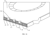
- FIG. 15 is a schematic diagram of a structure of a fan according to another embodiment of this application; and FIG. 16 is a schematic diagram of a structure of the fan shown in FIG. 15 from another perspective.
- Differences from the embodiment shown in FIG. 7 are that the first flow guiding inlet 561 is only disposed on the end cover 56, and the first sleeve 61 is disposed between the end cover 56 and the first guide plate 63.
- the end wall surface 613 of the first sleeve 61 is bonded or fixedly welded to the first guide surface, so that the first sleeve 61 and the end cover are sealed and fixedly connected.
- the flow guiding member 6 is fastened by a fixing force between the end wall surface 613 and the first guide surface.
- the second flow guiding inlet is not disposed on the bottom cover 58, and the second sleeve 62 is not disposed between the bottom cover and the second guide plate 64, so as to simplify a structure of the flow guiding member 6 and reduce a weight of the fan.
- the second flow guiding inlet 581 is only disposed on the bottom cover 58, and the second sleeve 62 is disposed between the bottom cover 58 and the second guide plate 64.
- the first flow guiding inlet is not disposed on the end cover 56, and the first sleeve 61 is not disposed between the end cover 56 and the first guide plate 63, so as to simplify a structure of the flow guiding member 6 and reduce a weight of the fan.
Landscapes
- Engineering & Computer Science (AREA)
- General Engineering & Computer Science (AREA)
- Theoretical Computer Science (AREA)
- Mechanical Engineering (AREA)
- Computer Hardware Design (AREA)
- Physics & Mathematics (AREA)
- Human Computer Interaction (AREA)
- General Physics & Mathematics (AREA)
- Mathematical Physics (AREA)
- Structures Of Non-Positive Displacement Pumps (AREA)
Abstract
Description
- This application claims priority to
Chinese Patent Application No. 2021112113405, filed with the China National Intellectual Property Administration on October 18, 2021 - This application relates to the field of heat dissipation technologies for electronic products, and in particular, to a fan and an electronic device.
- Currently, electronic components such as processors inside electronic devices will emit heat during operation. If the heat emitted by the electronic components during operation cannot be dissipated in a timely manner, the electronic devices will stop operating, and in severe cases, the processors may be burned out. To resolve the foregoing problem, existing manufacturers have arranged fans in electronic devices to dissipate heat from components such as processors. However, existing fans have poor heat dissipation capabilities.
- This application provides a fan and an electronic device, so as to improve a heat dissipation effect and prevent overheating of electronic components such as processors.
- According to a first aspect, this application provides a fan, including a body. The body includes an end cover, a bottom cover, a peripheral plate, blades, and a flow guiding member; the end cover and the bottom cover are opposite and spaced apart, two opposite sides of the peripheral plate in a thickness direction of the fan are connected to the end cover and the bottom cover respectively; the end cover, the bottom cover, and the peripheral plate form an air duct extending in a length direction of the fan, and the blades and the flow guiding member are mounted between the end cover and the bottom cover.
- The air duct includes an air inlet area and an air outlet area that are sequentially distributed and communicated in the length direction of the fan; the end cover is provided with an air inlet communicated with the air inlet area; a part between the end cover and the bottom cover is not connected by a connecting plate to form an air outlet; the air outlet area is corresponding to the air outlet and is communicated with the air outlet; and the blades are located in the air inlet area, and the flow guiding member is located in the air outlet area.
- The flow guiding member includes a first guide plate, a second guide plate, and a sleeve; the end cover, the first guide plate, the second guide plate, and the bottom cover are sequentially laminated and spaced apart in the thickness direction of the fan, so that a first channel is formed between the first guide plate and an inner wall of the air duct, the first guide plate and the second guide plate are oppositely spaced apart to form a second channel, and a third channel is formed between the second guide plate and the inner wall of the air duct; and the first channel, the second channel, and the third channel are sequentially disposed in the thickness direction of the fan.
- The sleeve is located in the first channel or the third channel, and includes a flow guiding cavity; one side that is of the second channel and that faces the air inlet area is isolated from the air inlet area, one side that is of the second channel and that faces away from the air inlet area forms a flow guiding outlet, and the flow guiding outlet and the air outlet face the same direction and are communicated.
- In the length direction of the fan, the air inlet area, the first channel, and the air outlet are sequentially communicated to form an air flow path, and the air inlet area, the third channel, and the air outlet are sequentially communicated to form another air flow path. In the thickness direction of the fan, the flow guiding inlet, the flow guiding cavity, and the second channel are sequentially communicated; and in the length direction of the fan, the second channel is also communicated with the flow guiding outlet and the air outlet, and finally the flow guiding inlet, the flow guiding cavity, the second channel, the flow guiding outlet, and the air outlet are sequentially communicated to form still another air flow path.
- In this embodiment, when the fan is operating, the blades in the air inlet area rotate to allow outside air to enter the air inlet area from the air inlet to form a main airflow, and then the main airflow flows from the air inlet area to the air outlet area, and finally blows out through the air outlet. When the main airflow flows to the air outlet area, because the second channel is separated from the air inlet area, the main airflow is divided into two streams to enter the first channel and the third channel respectively. Because spaces of the first channel and the third channel are smaller than a space of the air inlet area, a flow rate of the main airflow divided into two streams is increased after entering the first channel and the third channel. When two streams of high-speed main airflow flow through the flow guiding outlet on one side that is of the second channel and that is away from the air inlet area, negative pressure areas are formed on two sides of the flow guiding outlet. Air pressures in the negative pressure areas are lower than an air pressure in the second channel, resulting in a differential pressure between air pressures in the negative pressure areas and the second channel. Under an action of the differential pressure, outside air is induced to enter the flow guiding cavity from the flow guiding inlet to form an induced airflow, then the induced airflow enters the second channel from the flow guiding cavity, finally flows to the air outlet through the flow guiding outlet, and then blows out from the air outlet. When flowing to the air outlet, the two streams of high-speed main airflow rub against the body at the air outlet. Under an action of friction, the high-speed main airflow drives ambient air to generate a driven airflow. Therefore, at the air outlet of the fan, a total air output of the fan includes three parts: the main airflow, the induced airflow, and the driven airflow. Compared with a conventional component without the flow guiding member, the air output is significantly increased, and therefore, heat dissipation efficiency is improved.
- Because the sleeve is located in the first channel or the third channel, the main airflow is blocked by the sleeve when flowing through a position where the sleeve is located. In this case, a flow rate of the main airflow is further increased, so that the differential pressure between air pressures in the negative pressure areas and the second channel is more significant. Therefore, more air is induced to enter the flow guiding cavity to form an induced airflow with a larger air volume.
- In an embodiment, the body includes an end cover, the end cover forms an inner wall that is of the air duct and that is corresponding to the first guide plate, the sleeve includes a first sleeve, and the first sleeve is located in the first channel, and is hermetically connected to the end cover and the first guide plate respectively along two opposite ends in the thickness direction of the fan; the flow guiding inlet includes a first flow guiding inlet formed on the end cover, the flow guiding cavity includes a first flow guiding cavity formed on the first sleeve, and the first flow guiding cavity is communicated with the first flow guiding inlet and the second channel. The first sleeve is disposed, and a flow guiding cavity of the first sleeve is referred to as the first flow guiding cavity. Then a flow rate of a part of the main airflow entering the first channel is further increased due to blocking of the first sleeve. When the main airflow in the first channel flows through the flow guiding outlet, the differential pressure between air pressures in the negative pressure areas and the second channel is more significant. Under an action of the differential pressure, outside air enters the first flow guiding cavity from the first flow guiding inlet to form a first induced airflow, the first induced airflow then enters the second channel from the first flow guiding cavity, and finally flows to the air outlet through the flow guiding outlet, thereby increasing the total air output of the fan.
- In an embodiment, the first guide plate is disposed around a periphery of the first sleeve, so that the first channel surrounds the periphery of the first sleeve. Therefore, the first sleeve is located in the middle of the first channel in the length direction of the fan. In this case, the flow rate of the part of the main airflow entering the first channel is increased once due to a spatial difference between the first channel and the air inlet area, and the flow rate is increased once again under blocking of the first sleeve, so that the part of the main airflow in the first channel may be accelerated twice.
- In an embodiment, an edge that is of the first guide plate and that faces the air inlet area is aligned with a part of an edge of the first sleeve. Therefore, the first sleeve is located at an edge that is of the first channel and that faces the air inlet area. In this case, the flow rate of the part of the main airflow entering the first channel is increased rapidly due to the spatial difference between the first channel and the air inlet area and blocking of the first sleeve.
- In an embodiment, the sleeve includes a plurality of first sleeves, the flow guiding inlet includes a plurality of first flow guiding inlets formed on the end cover, and the plurality of first flow guiding inlets are in a one-to-one communication with the plurality of first sleeves. The plurality of first sleeves and the plurality of corresponding first flow guiding inlets are disposed, so that an air volume of the first induced airflow is increased, thereby further increasing the total air output of the fan.
- In an embodiment, the plurality of first sleeves and the plurality of first flow guiding inlets are equally spaced apart in the thickness direction of the fan. Therefore, the first induced airflow is evenly distributed, so that air outflow uniformity at the air outlet may be increased.
- In an embodiment, the body includes a bottom cover, the bottom cover forms an inner wall that is of the air duct and that is corresponding to the second guide plate, the sleeve includes a second sleeve, and the second sleeve is located in the third channel, and is hermetically connected to the bottom cover and the second guide plate respectively along two opposite ends in the thickness direction of the fan; and the flow guiding inlet includes a second flow guiding inlet formed on the bottom cover, the flow guiding cavity includes a second flow guiding cavity formed on the second sleeve, and the second flow guiding cavity is communicated with the second flow guiding inlet and the second channel. The second sleeve is disposed, and a flow guiding cavity of the second sleeve is referred to as the second flow guiding cavity. Then a flow rate of a part of the main airflow entering the third channel is further increased due to blocking of the second sleeve. When the main airflow in the third channel flows through the flow guiding outlet, the differential pressure between air pressures in the negative pressure areas and the second channel is more significant. Under an action of the differential pressure, outside air enters the flow guiding cavity of the second sleeve from the second flow guiding inlet to form a second induced airflow, the second induced airflow then enters the second channel from the second flow guiding cavity, and finally flows to the air outlet through the flow guiding outlet, thereby increasing the total air output of the fan.
- In an embodiment, the second guide plate is disposed around a periphery of the second sleeve, so that the third channel surrounds the periphery of the second sleeve. Therefore, the second sleeve is located in the middle of the third channel in the length direction of the fan. In this case, the flow rate of the part of the main airflow entering the third channel is increased once due to a spatial difference between the third channel and the air inlet area, and the flow rate is increased once again under blocking of the second sleeve, so that the part of the main airflow in the third channel may be accelerated twice.
- In an embodiment, the sleeve includes a plurality of second sleeves, the flow guiding inlet includes a plurality of second flow guiding inlets formed on the bottom cover, and the plurality of second flow guiding inlets are communicated with the plurality of second sleeves in a one-to-one correspondence. The plurality of second sleeves and the plurality of corresponding second flow guiding inlets are disposed, so that an air volume of the second induced airflow may be increased, thereby further increasing the total air output of the fan.
- In an embodiment, the plurality of second sleeves and the plurality of second flow guiding inlets are equally spaced apart in a width direction of the fan. Therefore, the second induced airflow is evenly distributed, so that air outflow uniformity at the air outlet may be increased.
- In an embodiment, in a direction perpendicular to the thickness direction, the flow guiding inlet and the flow guiding cavity are opposite, and have the same cross-sectional area and shape. Therefore, compared with a situation in which the flow guiding inlet and the flow guiding cavity are not aligned, the flow guiding inlet and the flow guiding cavity are aligned, so that a resistance to an induced airflow may be reduced, thereby reducing losses of the induced airflow, and ensuring that almost all of the induced airflow enters the second channel.
- In an embodiment, in the length direction of the fan, widths of the first guide plate, the second guide plate, and the air outlet area are the same. Therefore, the first guide plate, the second baffle, the end cover, and the bottom cover are flush at the air outlet, so as to facilitate machining.
- In an embodiment, the air outlet area includes a mounting area and a guide area, the mounting area is corresponding to the air inlet area and is communicated with the air inlet area, and the guide area is corresponding to the air outlet and is communicated with the air outlet; and the flow guiding member is mounted in the mounting area, and in the length direction of the fan, widths of the first guide plate, the second guide plate, and the mounting area are the same. Therefore, the first guide plate and the second guide plate are retracted with respect to the air outlet to be hidden in the air duct, so as to reduce a weight of the fan, prevent the first guide plate and the second guide plate from shielding the guide area, guide an airflow in the guide area, and provide a surface with a Coanda effect.
- In an embodiment, the body includes an end cover and a bottom cover that are opposite and spaced apart, the end cover includes a first guide surface facing the air duct, and a first convex portion is formed in the middle of a part that is of the first guide surface and that faces the guide area; and the bottom cover includes a second guide surface facing the air duct, a second convex portion is formed in the middle of a part that is of the second guide surface and that faces the guide area, and the first convex portion and the second convex portion protrude toward each other. Therefore, the first guide surface and the second guide surface become curved surfaces with a Coanda effect, and the surfaces with the Coanda effect enable an airflow to flow more smoothly, thereby reducing turbulence at the air outlet and reducing air volume losses.
- In an embodiment, the sleeve includes an inner wall surface facing the flow guiding cavity, and an outer wall surface facing away from the inner wall surface, and the outer wall surface is streamlined. The streamlined outer wall surface has a small resistance to an airflow, and when the airflow flows through the outer wall surface, air volume losses are small.
- In an embodiment, the flow guiding member further includes a connecting plate, two opposite sides of the connecting plate in the thickness direction of the fan are respectively connected to the first guide plate and the second guide plate, the connecting plate separates the second channel from the air inlet area, and sides that are of the first guide plate and the second guide plate and that face away from the connecting plate face the air outlet area and form the flow guiding outlet. The connecting plate connects sides that are of the first guide plate and the second guide plate and that face the air inlet area, thereby isolating the second channel from the air inlet area, and preventing the main airflow in the air inlet area from flowing into the second channel.
- In an embodiment, the connecting plate is an arc-shaped sheet. The connecting plate is arc-shaped, so that a resistance to an airflow may be reduced, and losses of the airflow flowing through the connecting plate may be reduced.
- In an embodiment, the connecting plate is a rectangular sheet.
- In an embodiment, the air duct further includes a conveying area, and the conveying area is located between the air inlet area and the air outlet area, and is communicated with the air inlet area and the air outlet area respectively. The conveying area separates the air inlet area from the air outlet area, so that the blades located in the air inlet area are separated from the flow guiding member located in the air outlet area to prevent the blades from interfering with the flow guiding member when rotating.
- In an embodiment, the body includes an end cover, a bottom cover, and a peripheral plate, the end cover and the bottom cover are opposite and spaced apart, two opposite sides of the peripheral plate in the thickness direction of the fan are connected to the end cover and the bottom cover respectively, the end cover, the bottom cover, and the peripheral plate form the air duct, the end cover and the bottom cover form the air outlet, and the flow guiding inlet is formed on the end cover and/or the bottom cover; and the flow guiding member is mounted between the end cover and the bottom cover. Therefore, the body has a simple structure, is easy to machine, and require low costs.
- In an embodiment, the bottom cover, the peripheral plate, and the flow guiding member are integrally formed into a base, and the end cover is detachably connected to the peripheral plate; the sleeve includes a first sleeve, the first sleeve is located in the first channel and includes an end wall surface facing the end cover, and the end wall surface is hermetically bonded to the end cover. Therefore, machining is easy, and the end cover can be easily removed to overhaul components such as the blades. In addition, the end wall surface is bonded to the end cover to prevent the flow guiding cavity from being communicated with the first channel or the third channel, and prevent the main airflow from entering the second channel.
- According to a second aspect, an embodiment of this application provides an electronic device, including a housing and a heat sink, where the housing includes an accommodating cavity, and an air vent and a thermovent that are communicated with the accommodating cavity, the heat sink is mounted in the accommodating cavity, the heat sink includes the fan according to the first aspect of this embodiment of this application, the air inlet of the fan faces the air vent, and the air outlet of the fan faces the thermovent.
- To describe technical solutions in embodiments or the background of this application more clearly, the following describes accompanying drawings required in embodiments or the background of this application.
-
FIG. 1 is a schematic diagram of a structure of an electronic device in a state according to an embodiment of this application; -
FIG. 2 is a schematic diagram of a structure of a housing part of the electronic device shown inFIG. 1 ; -
FIG. 3 is a schematic diagram of a structure of a fan in the housing shown inFIG. 2 ; -
FIG. 4 is a schematic diagram of a structure of an end cover of the fan shown inFIG. 3 ; -
FIG. 5 is a schematic diagram of a structure of a base of the fan shown inFIG. 3 ; -
FIG. 6 is a schematic diagram showing an airflow direction of the fan shown inFIG. 3 ; -
FIG. 7 is a schematic diagram of a partially internal structure of the fan shown inFIG. 3 ; -
FIG. 8 is a sectional view taken along an A-A direction inFIG. 3 ; -
FIG. 9 is a sectional view taken along a B-B direction inFIG. 3 ; -
FIG. 10 is a sectional view taken along a C-C direction inFIG. 6 ; -
FIG. 11 is a schematic diagram showing an airflow in the schematic diagram of the internal structure shown inFIG. 7 ; -
FIG. 12 is a schematic diagram of a partially internal structure according to another implementation of the fan shown inFIG. 3 ; -
FIG. 13 is a schematic diagram of a partially internal structure according to still another implementation of the fan shown inFIG. 3 ; -
FIG. 14 is a schematic diagram of a partially internal structure according to yet another implementation of the fan shown inFIG. 3 ; -
FIG. 15 is a schematic diagram of a structure of a fan according to another embodiment of this application; and -
FIG. 16 is a schematic diagram of a structure of the fan shown inFIG. 15 from another perspective. - Embodiments of this application will be described with reference to accompanying drawings in embodiments of this application.
- Referring to
FIG. 1 andFIG. 2 ,FIG. 1 is a schematic diagram of a structure of an electronic device according to an embodiment of this application in a state; andFIG. 2 is a schematic diagram of a structure of a housing of the electronic device shown inFIG. 1 in an open state. An embodiment of this application provides anelectronic device 1000, and theelectronic device 1000 is an electronic product such as a game console, a notebook computer, a personal digital assistant, a learning machine, and a tablet computer. In this embodiment, that theelectronic device 1000 is a notebook computer is used as an example for description. - For ease of description, a length direction of the
electronic device 1000 is defined as an X-axis direction, a width direction of theelectronic device 1000 is defined as a Y-axis direction, and a thickness direction of theelectronic device 1000 is defined as a Z-axis direction. The X-axis direction, the Y-axis direction, and the Z-axis direction are perpendicular to each other. - In this embodiment, the
electronic device 1000 includes adisplay 1, arotating shaft member 2, and amain body 3. Thedisplay 1 is connected to themain body 3 by using therotating shaft member 2, and thedisplay 1 may be unfolded or folded with respect to themain body 3. When thedisplay 1 is unfolded with respect to themain body 3, thedisplay 1 is at an angle to themain body 3, and theelectronic device 1000 may be used by a user; and when thedisplay 1 is folded with respect to themain body 3, theelectronic device 1000 is in a standby state or shutdown state for easy storage. - In this embodiment, the
display 1 includes adisplay surface 11 and anappearance surface 12 that face away from each other. When thedisplay 1 is folded with respect to themain body 3, thedisplay surface 11 is attached to themain body 3, and theappearance surface 12 is exposed to be in a visible state; and when thedisplay 1 is unfolded with respect to themain body 3, thedisplay surface 11 is in a visible state for observation and operation by the user. - The
rotating shaft member 2 is a hinge connected between thedisplay 1 and themain body 3. Therotating shaft member 2 is a rotating structure between thedisplay 1 and themain body 3 to implement free rotation of thedisplay 1 with respect to themain body 3. - The
main body 3 includes ahousing 31, akeyboard 32, electronic components (not marked in the figure), and aheat sink 4. Thekeyboard 32 is mounted on thehousing 31, and thekeyboard 32 is exposed with respect to thehousing 31 for the user to operate thekeyboard 32. The electronic components and theheat sink 4 are mounted inside thehousing 31. The electronic components include acircuit board 33, aprocessor 34, a memory bank, a video card, and the like. Theprocessor 34, the memory bank, and the video card are integrated on thecircuit board 33. Specifically, thekeyboard 32 is electrically connected to theprocessor 34, the user may operate thekeyboard 32 to generate an operation signal, and theprocessor 34 may process the operation signal. Theheat sink 4 is connected to the electronic components, and theheat sink 4 dissipates heat generated during operation of the electronic components, especially obvious heat generated when theprocessor 34 and the video card are operating. After heat dissipation, theheat sink 4 can prevent the electronic components from failure due to overheating. - The
housing 31 is cuboid, including a mountingwall 311, abottom wall 312, aperipheral wall 313, a mountingcavity 314, athermovent 315, and an air vent. The mountingwall 311 and thebottom wall 312 are disposed facing away from each other, and are respectively located on opposite sides of theperipheral wall 313. The mountingwall 311 is configured to mount thekeyboard 32. When thedisplay 1 is folded with respect to themain body 3, the mountingwall 311 is attached to thedisplay 1 to shield and protect thekeyboard 32; and when thedisplay 1 is unfolded with respect to themain body 3, the mountingwall 311 is exposed to expose thekeyboard 32 for the user to operate. Thebottom wall 312 may be in contact with a desktop to support theelectronic device 1000. The mountingwall 311, thebottom wall 312, and theperipheral wall 313 form a mountingcavity 314, and the mountingcavity 314 is configured to accommodate the electronic components and theheat sink 4. Thethermovent 315 is disposed on theperipheral wall 313, and is configured to be communicated with the outside and the mountingcavity 314, so that heat from the electronic components can flow to the outside through thethermovent 315. The air vent is disposed on thebottom wall 312, and is configured to be communicated with the outside and the mountingcavity 314, so that outside air can enter the mountingcavity 314 for thefan 5 of theheat sink 4 to operate. - The
heat sink 4 is mounted in the mountingcavity 314 of thehousing 31, and includes aheat pipe 41, a heat dissipation soldering iron (not shown in the figure), and thefan 5. Theheat pipe 41 is a copper pipe, and the heat dissipation soldering iron is laminated on the electronic components. One end of theheat pipe 41 is laminated on the heat dissipation soldering iron, and the other end is provided with fins, the fins are located at theair outlet 53 of thefan 5, and theair outlet 53 of thefan 5 faces thethermovent 315 of thehousing 31. When the notebook computer is operating, theheat pipe 41 conducts heat from the electronic components to the fins, and thefan 5 supplies an air volume to the fins to dissipate the heat from the fins, so as to transfer the heat from the electronic components to the outside through thethermovent 315. - Referring to
FIG. 3 to FIG. 5 , and with reference toFIG. 2 ,FIG. 3 is a schematic diagram of a structure of the fan shown inFIG. 2 ,FIG. 4 is a schematic diagram of a structure of an end cover of the fan shown inFIG. 3 , andFIG. 5 is a schematic diagram of a structure of a base of the fan shown inFIG. 3 . Thefan 5 is mounted in the mountingcavity 314. Thefan 5 includes anair duct 51, anair inlet 52, anair outlet 53,blades 54, and abody 55. Theair inlet 52, theair outlet 53, and theair duct 51 are all mounted on thebody 55, and theblades 54 are mounted in theair duct 51. Specifically, theair inlet 52 is configured to be communicated with the mountingcavity 314 of thehousing 31 and one side of theair duct 51, and theair outlet 53 is configured to be communicated with the mountingcavity 314 of thehousing 31 and the other side of theair duct 51. An airflow enters theair duct 51 through theair inlet 52 and flows out from theair outlet 53. - Referring to
FIG. 6 , and with reference toFIG. 3 to FIG. 5 ,FIG. 6 is a schematic diagram showing an airflow direction of the fan shown inFIG. 3 . When the notebook computer is operating, thefan 5 is operating. In this case, theblades 54 of thefan 5 rotate to allow outside air to enter theair duct 51 through the air vent of thehousing 31 and theair inlet 52 of thefan 5. The air entering theair duct 51 forms a main airflow a, and then flows out from theair outlet 53 and blows to the fins, so that heat from the fins can be dissipated through thethermovent 315 of thehousing 31. - Referring to
FIG. 3 to FIG. 5 , thebody 55 includes anend cover 56 and abase 57, thebase 57 includes abottom cover 58 and aperipheral plate 59, and theend cover 56 is detachably fastened to thebase 57. Theend cover 56 and thebottom cover 58 are oppositely disposed, and are respectively located on opposite sides of theperipheral plate 59 in the Z-axis direction. Theend cover 56 is detachably fastened to theperipheral plate 59, and theend cover 56, thebottom cover 58, and theperipheral plate 59 form theair duct 51. When thefan 5 is mounted in the mountingcavity 314, theend cover 56 is opposite to thebottom wall 312 of thehousing 31, and theair inlet 52 is disposed on theend cover 56, so that theair inlet 52 can be opposite to the air vent, thereby improving air intake efficiency. Theperipheral plate 59 is opposite to theperipheral wall 313 of thehousing 31, and theair outlet 53 is disposed on theperipheral plate 59, so that theair outlet 53 can be opposite to thethermovent 315, thereby improving heat dissipation efficiency. In other embodiments, theend cover 56 and the base 57 are integrally formed to strengthen a structural strength of thebody 55. - Referring to
FIG. 5 andFIG. 6 , theair duct 51 includes anair inlet area 511, a conveyingarea 512, and anair outlet area 513 that are distributed in the X-axis direction (air outlet direction) and sequentially communicated. Theair inlet area 511 is communicated with theair inlet 52, and theair outlet area 513 is communicated with theair outlet 53. Theblades 54 are mounted on thebottom cover 58, and are located in theair inlet area 511 of theair duct 51; and the conveyingarea 512 is located between theair inlet area 511 and theair outlet area 513 to prevent theblades 54 from touching a component mounted in theair outlet area 513 when rotating. When thefan 5 is operating, theblades 54 of thefan 5 rotate to allow air to enter theair inlet area 511 of theair duct 51 from theair inlet 52 of thefan 5. The main airflow a formed by the air entering theair inlet area 511 flows through the conveyingarea 512 to theair outlet area 513, and then flows out from theair outlet 53 and blows to the fins, so that heat from the fins can be dissipated through thethermovent 315 of thehousing 31. In other embodiments, theair duct 51 includes an air inlet area and an air outlet area, and no conveying area is provided. Therefore, a size of theair duct 51 in the X-axis direction may be reduced, thereby reducing a volume of the entire fan to save space. - Referring to
FIG. 3 and FIG. 4 , theair inlet 52 in this embodiment is circular, and is corresponding to and communicated with theair inlet area 511. When thefan 5 is mounted in the mountingcavity 314, theair inlet 52 is corresponding to the air vent of thehousing 31 and is communicated with the air vent of thehousing 31, and theair inlet 52 allows outside air to enter theair duct 51 through the air vent of thehousing 31. In other embodiments, theair inlet 52 is square, elliptical, trapezoidal, triangular, or the like, which may be set specifically based on a shape and a size of theend cover 56. - Referring to
FIG. 3 , theair outlet 53 is rectangular, and is corresponding to and communicated with theair outlet area 513. When thefan 5 is mounted in the mountingcavity 314, theair outlet 53 is corresponding to and communicated with thethermovent 315 of thehousing 31, and theair outlet 53 allows the main airflow formed through rotation of theblades 54 to blow to the fins, and is finally dissipated from thethermovent 315. In other embodiments, theair outlet 53 is trapezoidal, elliptical, or the like, which may be set specifically based on a shape and a size of theperipheral plate 59. - Referring to
FIG. 5 , theblades 54 are made of a plastic to reduce a weight of theheat sink 4. Theblades 54 are mounted on thebottom cover 58, and are located in theair inlet area 511. At least a part of theblades 54 is exposed with respect to theair inlet 52. Theblades 54 may be driven by a motor to rotate, so that the air entering theair duct 51 forms the main airflow. There are a plurality ofblades 54, where "a plurality of' means two or more. The plurality ofblades 54 are fastened to a rotating shaft disposed on thebottom cover 58, and the rotating shaft rotates to drive theblades 54 to rotate, so that theblades 54 drive air to form the main airflow. - The
body 55 is made of a stainless steel or a plastic to enhance a structural strength of thefan 5, thereby prolonging a service life of thefan 5. Referring toFIG. 7 , and with reference toFIG. 6 ,FIG. 7 is a schematic diagram of a partially internal structure of the fan shown inFIG. 3 . Thebody 55 further includes aflow guiding member 6. - Specifically, the
air outlet area 513 includes a mountingarea 515 and aguide area 514 that are distributed in the X-axis direction, the mountingarea 515 faces the conveyingarea 512, and theguide area 514 faces theair outlet 53. Theflow guiding member 6 is mounted in the mountingarea 515 of theair duct 51, and is fixedly connected to thebottom cover 58. Because the conveyingarea 512 is located between the mountingarea 515 and theair inlet area 511, theblades 54 in theair inlet area 511 may be prevented from touching theflow guiding member 6 to increase a safety coefficient. - In this embodiment, referring to
FIG. 5 , thebottom cover 58, theperipheral plate 59 and theflow guiding member 6 are integrally formed into abase 57, and theend cover 56 and the base 57 are detachably fastened by using a buckle and/or a screw, so that theend cover 56 may be separated from the base 57 to expose the mountingcavity 314 for cleaning, maintaining, or replacing theblades 54. In other embodiments, thebottom cover 58, theperipheral plate 59, and theflow guiding member 6 are separately formed, and then fixedly connected through welding. - In this embodiment, with reference to
FIG. 4 andFIG. 7 , theend cover 56 is a sheet, and includes a firstflow guiding inlet 561, afirst guide surface 562, afirst appearance surface 563, and a firstperipheral wall surface 564. The firstflow guiding inlet 561 penetrates through thefirst guide surface 562 and thefirst appearance surface 563, and is configured to correspond to theair outlet area 513 of theair duct 51. Across section of the firstflow guiding inlet 561 is streamlined, and the firstflow guiding inlet 561 is configured to be communicated with the interior of theflow guiding member 6, so that air enters the interior of theflow guiding member 6 along the firstflow guiding inlet 561 to form a first inducedairflow b 1, so as to increase a total air output. Thefirst guide surface 562 is disposed away from thefirst appearance surface 563 in the Z-axis direction, and the firstperipheral wall surface 564 is connected between thefirst guide surface 562 and thefirst appearance surface 563. Thefirst guide surface 562 faces the air duct, and when thefan 5 is not mounted in the mountingcavity 314, thefirst appearance surface 563 is located outside and is in a visible state. At least a part of the firstperipheral wall surface 564 is located at the air outlet, and is configured to form theair outlet 53 with thebase 57. In other embodiments, the firstflow guiding inlet 561 is circular, elliptical, square, triangular, or the like, which is not limited in this application. - Referring to
FIG. 8 to FIG. 10 ,FIG. 8 is a sectional view taken along an A-A direction inFIG. 3 ;FIG. 9 is a sectional view taken along a B-B direction inFIG. 3 ; andFIG. 10 is a sectional view taken along a C-C direction inFIG. 6 ; and with reference toFIG. 5 , thebottom cover 58 of thebase 57 is a sheet, and thebottom cover 58 includes a secondflow guiding inlet 581, asecond guide surface 582, asecond appearance surface 583, and a secondperipheral wall surface 584. The secondflow guiding inlet 581 penetrates through thesecond guide surface 582 and thesecond appearance surface 583, and is configured to correspond to theair outlet area 513 of theair duct 51; and the secondflow guiding inlet 581 is streamlined, and the secondflow guiding inlet 581 is configured to be communicated with the interior of theflow guiding member 6, so that air enters the interior of theflow guiding member 6 along the secondflow guiding inlet 581 to form a second induced airflow, so as to increase the total air output. Thesecond guide surface 582 is disposed away from thesecond appearance surface 583, and the secondperipheral wall surface 584 is connected between thesecond guide surface 582 and thesecond appearance surface 583. Thesecond guide surface 582 faces the air duct, and when the fan is not mounted in the mountingcavity 314, thesecond appearance surface 583 is located outside and is in a visible state. At least a part of the secondperipheral wall surface 584 is located at the air outlet, and is configured to form theair outlet 53 with theend cover 56. In other embodiments, the secondflow guiding inlet 581 is circular, elliptical, square, triangular, or the like, which is not limited in this application. - Referring to
FIG. 7 andFIG. 9 , sizes and shapes of the firstflow guiding inlet 561 and the secondflow guiding inlet 581 are the same, and theend cover 56 and thebottom cover 58 are laminated. In the Z-axis direction, the firstflow guiding inlet 561 and the secondflow guiding inlet 581 are oppositely communicated, and air volumes of the first induced airflow b1 and a second induced airflow b2 generated by the firstflow guiding inlet 561 and the secondflow guiding inlet 581 are basically the same. Because the first induced airflow b1 flows from top down and the second induced airflow b2 flows from bottom up, when the air volumes of the first induced airflow b1 and the second induced airflow b2 are basically the same, most of the air volumes of the first induced airflow b1 and the second induced airflow b2 are mixed to form an induced airflow b, so as to reduce losses of the first induced airflow b1 flowing out of the secondflow guiding inlet 581 and losses of the second induced airflow b2 flowing out of the firstflow guiding inlet 561. - Referring to
FIG. 5 , theperipheral plate 59 is a sheet, and is located between theend cover 56 and thebottom cover 58. Theperipheral plate 59 does not shield parts of the firstperipheral wall surface 564 and the secondperipheral wall surface 584 to form theair outlet 53 of theair duct 51 together with theend cover 56 and thebottom cover 58. The parts of firstperipheral wall surface 564 and the secondperipheral wall surface 584 are located on two sides of theair outlet 53 in the Z-axis direction. - Referring to
FIG. 5 andFIG. 7 , theflow guiding member 6 includes afirst guide plate 63, asecond guide plate 64, and a sleeve, a first channel is formed between thefirst guide plate 63 and an inner wall of theair duct 51, thefirst guide plate 63 and thesecond guide plate 64 are oppositely spaced apart to form a second channel, and a third channel is formed between thesecond guide plate 64 and the inner wall of theair duct 51; the first channel, the second channel, and the third channel are sequentially disposed in the thickness direction of the fan; and the sleeve is disposed in the first channel and/or the third channel, and the sleeve includes a flow guiding cavity. One side that is of the second channel and that faces theair inlet area 511 is isolated from theair inlet area 511, and one side that is of the second channel and that faces away from theair inlet area 511 forms a flow guiding outlet, and the flow guiding outlet and the air outlet face the same direction and are communicated. In the length direction of the fan, theair inlet area 511, the first channel, and the air outlet are sequentially communicated, and theair inlet area 511, the third channel, and the air outlet are sequentially communicated; and in the thickness direction of the fan, the flow guiding inlet, the flow guiding cavity, and the second channel are sequentially communicated. The sleeve includes a first sleeve and/or a second sleeve, a flow guiding cavity of the first sleeve is a first flow guiding cavity, a flow guiding cavity of the second sleeve is a second flow guiding cavity, and the flow guiding inlet includes a first flow guiding inlet and/or a second flow guiding inlet. - The
air inlet area 511, the first channel, and the air outlet are sequentially communicated in the length direction of the fan to form a main airflow path, and theair inlet area 511, the third channel, the air outlet are sequentially communicated in the length direction of the fan to form another main airflow path, and the two main airflow paths are configured to circulate main airflows from rotation of the blades. Thefirst guide plate 63 and/or thesecond guide plate 64 are provided with a connecting hole corresponding to the flow guiding cavity of the sleeve, and the connecting hole is communicated with the flow guiding cavity and the second channel. The flow guiding inlet, the flow guiding cavity and the connecting hole are aligned and communicated in the thickness direction of the fan to form an induced airflow channel, and the induced airflow channel is configured to circulate induced airflows. - More specifically, in this embodiment, the
flow guiding member 6 is mounted in the mountingarea 515 of theair outlet area 513 of theair duct 51. Theflow guiding member 6 includes afirst sleeve 61, asecond sleeve 62, afirst guide plate 63, asecond guide plate 64, and a connectingplate 65; and thefirst sleeve 61, thefirst guide plate 63, the connectingplate 65, thesecond guide plate 64, and thesecond sleeve 62 are sequentially connected in the Z-axis direction. In addition, thefirst guide plate 63 and thesecond guide plate 64 surround peripheries of thefirst sleeve 61 and thesecond sleeve 62, respectively, thefirst guide plate 63 and thesecond guide plate 64 are oppositely spaced, and the connectingplate 65 is connected between thefirst guide plate 63 and thesecond guide plate 64; and thefirst sleeve 61 is connected to theend cover 56, and thesecond sleeve 62 is connected to thebottom cover 58. Theflow guiding member 6 is communicated with the firstflow guiding inlet 561 and the secondflow guiding inlet 581. - Referring to
FIG. 7 , after theend cover 56 and the base 57 are assembled, a first channel L1 is formed between thefirst guide plate 63 and theend cover 56 in the Z-axis direction. The first channel L1 surrounds a periphery of thefirst sleeve 61 and is communicated with the conveyingarea 512 and theair outlet 53. A second channel L2 is formed among thefirst guide plate 63, thesecond guide plate 64 and the connectingplate 65, and aflow guiding outlet 66 is formed on one side opposite to theair outlet 53. Theflow guiding outlet 66 faces theair outlet 53, so that the second channel L2 is communicated with theair outlet 53. In addition, the second channel L2 is isolated from the conveyingarea 512 by using the connectingplate 65. A third channel L3 is formed between thesecond guide plate 64 and thebottom cover 58. The third channel L3 surrounds a periphery of thesecond sleeve 62, and the third channel L3 is communicated with the conveyingarea 512 and theair outlet 53. In the Z-axis direction, the second channel L2 is located between the first channel L1 and the third channel L3. The firstflow guiding inlet 561 and the secondflow guiding inlet 581 are connected to the second channel L2 by using thefirst sleeve 61 and thesecond sleeve 62 respectively. - Referring to
FIG. 7 andFIG. 9 , two sides of thefirst sleeve 61 in the Z-axis direction are hermetically connected to theend cover 56 and thefirst guide plate 63 respectively. Thefirst sleeve 61 is provided with a firstflow guiding cavity 614 running in the Z-axis direction, and the firstflow guiding cavity 614 is communicated with both the first flow guiding inlet and the second channel L2. Two sides of thesecond sleeve 62 in the Z-axis direction are hermetically connected to thesecond guide plate 64 and thebottom cover 58 respectively. Thesecond sleeve 62 is provided with a secondflow guiding cavity 623 running in the Z-axis direction, and the secondflow guiding cavity 623 is communicated with both the second flow guiding inlet and the second channel L2. - Specifically, referring to
FIG. 7 andFIG. 9 , thefirst sleeve 61 is cylindrical, and includes a firstinner wall surface 611, a firstouter wall surface 612, and anend wall surface 613. The firstinner wall surface 611 faces the firstflow guiding cavity 614, the firstouter wall surface 612 faces away from the firstinner wall surface 611, and two sides of theend wall surface 613 are connected to the firstinner wall surface 611 and the firstouter wall surface 612 respectively. Theend wall surface 613 faces theend cover 56, and is hermetically connected to one surface of theend cover 56, and sides that are of the firstinner wall surface 611 and the firstouter wall surface 612 and that are away from theend wall surface 613 are hermetically connected to thefirst guide plate 63. An adhesive is applied in an area that is of thefirst guide surface 562 of theend cover 56 and that is corresponding to theend wall surface 613, or applied on theend wall surface 613. When theend cover 56 is buckled on thebase 57, the adhesive fixedly adheres thefirst guide surface 562 and theend wall surface 613, so as to hermetically connect theend wall surface 613 and theend cover 56. In this embodiment, theflow guiding member 6 is integrally formed, so that sides that are of the firstinner wall surface 611 and the firstouter wall surface 612 and that are away from theend wall surface 613 can be hermetically connected to thefirst guide plate 63. - Referring to
FIG. 7 andFIG. 9 , thesecond sleeve 62 is cylindrical, and includes a secondinner wall surface 621, a secondouter wall surface 622, and a secondflow guiding cavity 623. The secondinner wall surface 621 faces the secondflow guiding cavity 623, the secondouter wall surface 622 faces away from the secondinner wall surface 621, sides that are of the firstinner wall surface 611 and the secondouter wall surface 622 in the Z-axis direction are hermetically connected to thesecond guide plate 64 respectively, and the other sides are respectively connected to thebottom cover 58. Specifically, theflow guiding member 6 and the bottom cover are integrally formed, so that the firstinner wall surface 611 and the secondinner wall surface 621 are hermetically connected to thesecond guide plate 64 and thebottom cover 58. - Referring to
FIG. 7 , thefirst guide plate 63 is disposed around the periphery of thefirst sleeve 61, and includes afirst surface 631 and asecond surface 632 that face away from each other in the Z-axis direction, and thefirst surface 631 is connected to the firstouter wall surface 612; and thefirst guide surface 562 and thefirst surface 631 form the first channel L1. Thesecond guide plate 64 and thefirst guide plate 63 are oppositely spaced, and the second channel L2 is formed between thefirst guide plate 63 and thesecond guide plate 64. Thesecond guide plate 64 is disposed around the periphery of thesecond sleeve 62, and includes athird surface 641 and afourth surface 642 that face away from each other in the Z-axis direction. Thethird surface 641 is connected to the secondouter wall surface 622, and thefourth surface 642 and thesecond guide surface 582 form the third channel L3; thesecond surface 632 and thethird surface 641 face the second channel L2, and one side that is of thefirst sleeve 61 and that is connected to thefirst guide plate 63 and one end face that is of thesecond sleeve 62 and that is connected to thesecond guide plate 64 face the second channel L2. - Referring to
FIG. 9 , in a direction perpendicular to a Z axis, sectional areas and shapes of the firstflow guiding cavity 614, the secondflow guiding cavity 623, the firstflow guiding inlet 561, and the secondflow guiding inlet 581 are the same, that is, projections of the firstflow guiding cavity 614, the secondflow guiding cavity 623, the firstflow guiding inlet 561, and the secondflow guiding inlet 581 in the direction perpendicular to the Z axis coincide, so as to facilitate machining, and ensure that airflows can smoothly circulate to the firstflow guiding cavity 614 and the secondflow guiding cavity 623 after entering the firstflow guiding inlet 561 and the secondflow guiding inlet 581, thereby increasing an air volume of an induced airflow, and preventing airflow damage due to misalignment of the cavities and the inlets. - Referring to
FIG. 7, FIG. 8 , andFIG. 9 , the connectingplate 65 is connected between thefirst guide plate 63 and thesecond guide plate 64. Specifically, two sides of the connectingplate 65 in the Z-axis direction are respectively connected to sides that are of thefirst guide plate 63 and thesecond guide plate 64 and that face the conveyingarea 512, so as to isolate the second channel L2 from the conveyingarea 512, and prevent an airflow from the conveyingarea 512 from flowing into the second channel L2; sides that are of thefirst guide plate 63 and thesecond guide plate 64 and that face theair outlet 53 are spaced apart to form theflow guiding outlet 66, and theflow guiding outlet 66 faces theair outlet 53, so that the second channel L2 is communicated with theair outlet 53. In this embodiment, the connectingplate 65 is a rectangular sheet to facilitate machining. Referring toFIG. 7, FIG. 8 , andFIG. 10 , the connectingplate 65 extends to seal two opposite sides of thefirst guide plate 63 and thesecond guide plate 64 along a Y axis. In this case, the second channel L2 has a structure with three sides closed and one side open, and the open side is theflow guiding outlet 66. In other embodiments, the connectingplate 65 seals only one side that is of the first channel L1 and that faces the conveyingarea 512, and the other three sides of the second channel L2 are open. In this case, a weight of the connectingplate 65 is reduced, which facilitates a lightweight design of the entire fan. In other embodiments, referring toFIG. 12, FIG. 12 is a schematic diagram of a partially internal structure according to another implementation of the fan shown inFIG. 3 . The connectingplate 65 is an arc-shaped sheet. In this case, one side that is of the connectingplate 65 and that faces away from the second channel L2 has a low resistance to a main airflow that flows through, so as to reduce losses of the main airflow. One side that is of the connectingplate 65 and that faces the second channel L2 has a low resistance to an induced airflow, so as to reduce losses of the induced airflow. - In this embodiment, referring to
FIG. 11, FIG. 11 is a schematic diagram showing an airflow in the schematic diagram of the internal structure shown inFIG. 7 . With reference toFIG. 6 to FIG. 10 , when thefan 5 is operating, a main airflow a formed through rotation of theblades 54 flows in a direction from theair duct 51 to theair outlet 53. When flowing through theflow guiding member 6, the main airflow a will bypass the connectingplate 65 due to blocking of the connectingplate 65, and then flow into the first channel L1 and the third channel L3. Due to blocking of the connectingplate 65, a volume of an available space for the main airflow a is reduced suddenly, and a flow rate of the main airflow a is increased. A part of the main airflow a entering the first channel L1 is blocked by the firstouter wall surface 612 of thefirst sleeve 61, so that the volume of the available space is further reduced, and the flow rate is further increased. Based on the Bernoulli's principle, when the main airflow a flowing at a high speed in the first channel L1 flows through an upper side of theflow guiding outlet 66, a negative pressure area M will be formed near theflow guiding outlet 66. A differential pressure exists between air pressures in the negative pressure area M and the firstflow guiding cavity 614. Under an action of the differential pressure, induced air enters the firstflow guiding cavity 614 from the firstflow guiding inlet 561, thereby forming the first induced airflow b1. A part of the main airflow a entering the third channel L3 is blocked by the secondouter wall surface 622 of thesecond sleeve 62, so that the volume of the available space is further reduced, and the flow rate is further increased. Based on the Bernoulli's principle, when the main airflow a flowing at a high speed in the third channel L3 flows through a lower side of theflow guiding outlet 66, a negative pressure area M will be formed near theflow guiding outlet 66. A differential pressure exists between air pressures in the negative pressure area M and the secondflow guiding cavity 623. Under an action of the differential pressure, induced air enters the secondflow guiding cavity 623 from the secondflow guiding inlet 581, thereby forming the second induced airflow b2; and after the first induced airflow b1 and the second induced airflow b2 are mixed in the second channel L2 into an induced airflow b, the induced airflow b flows to theair outlet 53 of thefan 5 along theflow guiding outlet 66. When the main airflow a finally flows to theair outlet 53 after bypassing thefirst sleeve 61 and thesecond sleeve 62, the main airflow a will rub against the firstperipheral wall surface 564 and the secondperipheral wall surface 584 that are located on two sides of theair outlet 53. Under an action of friction, the main airflow a flowing at a high speed drives air around theair outlet 53 to generate a driven airflow c. In this case, an air output of thefan 5 includes three parts: the main airflow a, the induced airflow b, and the driven airflow c. Compared with a conventional component without theflow guiding member 6, the air output is significantly increased, and therefore, heat dissipation efficiency is improved. - Still referring to
FIG. 6 ,FIG. 7 andFIG. 11 , in this embodiment, in the X-axis direction, theflow guiding member 6 is mounted in the mountingarea 515, and theguide area 514 is formed between the mountingarea 515 and theair outlet 53. In this case, thefirst guide plate 63 and thesecond guide plate 64 are retracted with respect to the air outlet to be hidden in theair duct 51. Therefore, the main airflow a flows out of the first channel L1 and the third channel L3, and then needs to pass through theguide area 514 before reaching theair outlet 53; and the induced airflow b flows out of the second channel L2, and then also needs to pass through theguide area 514 before reaching theair outlet 53. Theguide area 514 may guide the induced airflow b and the main airflow a to make the airflows directional, and the directional airflows can slow down losses of airflow rates and increase an air output. - Referring to
FIG. 7 , in this embodiment, in the X-axis direction, a firstconvex portion 5624 is formed in the middle of a part that is of thefirst guide surface 562 and that faces theguide area 514, so that thefirst guide surface 562 is a surface with a Coanda effect. Specifically, in the X-axis direction, a part that is of thefirst guide surface 562 and that faces theair outlet area 513 includes afirst plane section 5621, afirst transition section 5622, and a firstcambered section 5623 that are sequentially connected. Thefirst transition section 5622 smoothly connects thefirst plane section 5621 and the firstcambered section 5623, so that thefirst guide surface 562 is smoother. Thefirst plane section 5621 and thefirst transition section 5622 face the first channel L1, and the firstcambered section 5623 faces theguide area 514. In the X-axis direction, the firstcambered section 5623 gradually inclines toward a direction close to thebottom cover 58, and then gradually inclines toward a direction away from thebottom cover 58, so that the firstconvex portion 5624 is formed in the middle of thefirst guide surface 562 in the X-axis direction, and the firstconvex portion 5624 extends in the Y-axis direction (thickness direction). Specifically, the middle is any position between two sides of the firstcambered section 5623 in the X-axis direction. Therefore, after an airflow flows out of the third channel L3 from the first channel L1, the airflow leaves an original flow direction and instead is attached to the firstcambered section 5623 to flow, so that the airflow can flow more smoothly, thereby reducing turbulence and increasing an air output. - Referring to
FIG. 7 , in the X-axis direction, a secondconvex portion 5824 is formed in the middle of a part that is of thesecond guide surface 582 and that faces theguide area 514, so that thesecond guide surface 582 is a surface with a Coanda effect. Specifically, in the X-axis direction, thesecond guide surface 582 includes asecond plane section 5821, asecond transition section 5822, and a second cambered section 5823 that are sequentially connected. Thesecond transition section 5822 smoothly connects thesecond plane section 5821 and the second cambered section 5823, so that thesecond guide surface 582 is smoother. Thesecond plane section 5821 and thesecond transition section 5822 face the second channel L2, and the second cambered section 5823 faces theguide area 514. In the X-axis direction, the second cambered section 5823 gradually inclines toward a direction close to theend cover 56, and then gradually inclines toward a direction away from theend cover 56, so that the secondconvex portion 5824 is formed in the middle of thesecond guide surface 582 in the X-axis direction, and the secondconvex portion 5824 extends in the Y-axis direction. Specifically, the middle is any position between two sides of the second cambered section in the X-axis direction. Therefore, after an airflow flows out of the third channel L3 from the first channel L1, the airflow leaves an original flow direction and instead is attached to the second cambered section 5823 to flow, so that the airflow can flow more smoothly, thereby reducing turbulence and increasing an air output. -
FIG. 13 is a schematic diagram of a partially internal structure according to still another implementation of the fan shown inFIG. 3 . In this implementation, a difference from that shown inFIG. 7 is that both thefirst guide surface 562 and thesecond guide surface 582 are flat for easy machining. -
FIG. 14 is a schematic diagram of a partially internal structure according to yet another implementation of the fan shown inFIG. 3 . In this implementation, theflow guiding member 6 is mounted in the air outlet area, and a size of theflow guiding member 6 in the X-axis direction is the same as that of the air outlet area. In this case, thefirst guide plate 63 and thesecond guide plate 64 are flush with theair outlet 53. Specifically, thefirst guide plate 63 and thesecond guide plate 64 each have one side and the other side that are disposed facing away from each other in the X-axis direction. In the X-axis direction, one side of thefirst guide plate 63 and one side of thesecond guide plate 64 are aligned with one side that is of theair outlet area 513 and that faces the conveyingarea 512, and the other side of thefirst guide plate 63 and the other side of thesecond guide plate 64 are aligned with theair outlet 53 to facilitate machining. - Referring to
FIG. 5 andFIG. 7 , in this embodiment, in the direction perpendicular to the Z axis, the firstouter wall surface 612 of thefirst sleeve 61 is arc-shaped, so that the firstouter wall surface 612 has a low resistance to a part of the main airflow a flowing in the first channel L1 to ensure that the main airflow a entering the first channel L1 has a high flow rate. In this way, a difference between air pressures in the negative pressure area M and the firstflow guiding cavity 614 is large, and an air volume of the first induced airflow b1 is large. Therefore, the air output is increased to further improve the heat dissipation efficiency. Specifically, in this embodiment, in the direction perpendicular to the Z axis, the firstouter wall surface 612 is streamlined, a relatively round part of the firstouter wall surface 612 faces the conveyingarea 512 of theair duct 51, and a relatively sharp part faces theair outlet 53. In other embodiments, in the direction perpendicular to the Z axis, the firstouter wall surface 612 is elliptical or circular. - Referring to
FIG. 7 , in the direction perpendicular to the Z axis, the secondouter wall surface 622 of thesecond sleeve 62 is arc-shaped, so that the secondouter wall surface 622 has a low resistance to a part of the main airflow a flowing in the third channel L3 to ensure that the main airflow a entering the third channel L3 has a high flow rate. In this way, a difference between air pressures in the negative pressure area M and the secondflow guiding cavity 623 is large, and an air volume of the second induced airflow b2 is large. Therefore, the air output is increased to further improve the heat dissipation efficiency. Specifically, in this embodiment, in the direction perpendicular to the Z axis, the secondouter wall surface 622 is streamlined, and a relatively round part of the secondouter wall surface 622 faces the conveyingarea 512 of theair duct 51, and a relatively sharp part faces theair outlet 53. In other embodiments, in the direction perpendicular to the Z axis, the secondouter wall surface 622 is elliptical or circular. - Referring to
FIG. 3 andFIG. 5 , in this embodiment, there are a plurality offirst sleeves 61, where "a plurality of' means two or more. A specific quantity of thefirst sleeves 61 may be determined based on a quantity of thebody 55. A larger size of thebody 55 in the Y-axis direction indicates that morefirst sleeves 61 may be provided. On the contrary, a smaller size of thebody 55 in the Y-axis direction indicates that fewerfirst sleeves 61 may be provided correspondingly. Specifically, a plurality offirst sleeves 61 are equally spaced apart in the Y-axis direction, and the main airflow a entering the first channel L1 flows through two adjacentfirst sleeves 61 in a plurality of streams, so as to increase a flow rate of the main airflow a flowing in the first channel L1, increase a differential pressure between the negative pressure area M and the firstflow guiding cavity 614, increase an air volume of the first induced airflow b1, and further increase a total air output. The plurality offirst sleeves 61 are equally spaced apart, so that a part of the main airflow a entering the first channel L1 is evenly divided into a plurality of streams, and when the plurality of streams of main airflow finally converge at theair outlet 53, an air volume of the entire airflow is relatively uniform, so that heat may be uniformly dissipated from all parts of the fins, thereby improving a heat dissipation effect. In other embodiments, the plurality offirst sleeves 61 are randomly distributed in the Y-axis direction, or are randomly distributed along the X axis. In other embodiments, thefan 5 includes afirst sleeve 61 to simplify a structure of thefan 5 and reduce a weight of thefan 5. - Similarly, there are a plurality of
second sleeves 62, where "a plurality of' means two or more. A specific quantity of thesecond sleeves 62 may be determined based on a quantity of thebody 55. A larger size of thebody 55 in the Y-axis direction indicates that moresecond sleeves 62 may be provided. On the contrary, a smaller size of thebody 55 in the Y-axis direction indicates that fewersecond sleeves 62 may be provided correspondingly. Specifically, a plurality ofsecond sleeves 62 are equally spaced apart in the Y-axis direction, and a part of the main airflow a entering the third channel L3 flows through two adjacentsecond sleeves 62 in a plurality of streams, so as to increase a flow rate of the main airflow a flowing in the third channel L3, increase a differential pressure between the negative pressure area M and the secondflow guiding cavity 623, increase an air volume of the second induced airflow b2, and further increase a total air output. The plurality ofsecond sleeves 62 are equally spaced apart, so that a part of the main airflow a entering the second channel L2 is evenly divided into a plurality of streams, and when the plurality of streams of main airflow finally converge at theair outlet 53, an air volume of the entire airflow is relatively uniform, so that heat may be uniformly dissipated from all parts of the fins, thereby improving a heat dissipation effect. In other embodiments, the plurality ofsecond sleeves 62 are randomly distributed in the Y-axis direction, or are randomly distributed along the X axis. In other embodiments, thefan 5 includes asecond sleeve 62 to simplify a structure of thefan 5 and reduce a weight of thefan 5. - In other embodiments, referring to
FIG. 15 andFIG. 16 ,FIG. 15 is a schematic diagram of a structure of a fan according to another embodiment of this application; andFIG. 16 is a schematic diagram of a structure of the fan shown inFIG. 15 from another perspective. Differences from the embodiment shown inFIG. 7 are that the firstflow guiding inlet 561 is only disposed on theend cover 56, and thefirst sleeve 61 is disposed between theend cover 56 and thefirst guide plate 63. Theend wall surface 613 of thefirst sleeve 61 is bonded or fixedly welded to the first guide surface, so that thefirst sleeve 61 and the end cover are sealed and fixedly connected. In this case, theflow guiding member 6 is fastened by a fixing force between theend wall surface 613 and the first guide surface. Differences from the embodiment shown inFIG. 7 are that the second flow guiding inlet is not disposed on thebottom cover 58, and thesecond sleeve 62 is not disposed between the bottom cover and thesecond guide plate 64, so as to simplify a structure of theflow guiding member 6 and reduce a weight of the fan. - In other embodiments, the second
flow guiding inlet 581 is only disposed on thebottom cover 58, and thesecond sleeve 62 is disposed between thebottom cover 58 and thesecond guide plate 64. Differences from the embodiment shown inFIG. 7 are that the first flow guiding inlet is not disposed on theend cover 56, and thefirst sleeve 61 is not disposed between theend cover 56 and thefirst guide plate 63, so as to simplify a structure of theflow guiding member 6 and reduce a weight of the fan. - The foregoing descriptions are merely some embodiments and implementations of this application, but are not intended to limit the protection scope of this application. Any variation or replacement readily figured out by a person skilled in the art within the technical scope disclosed in this application shall fall within the protection scope of this application. Therefore, the protection scope of this application shall be subject to the protection scope of the claims.
Claims (21)
- A fan, comprising a body, wherein an air duct, an air outlet and a flow guiding inlet that is communicated with the outside are formed in the body; and the air duct comprises an air inlet area and an air outlet area that are sequentially distributed and communicated in a length direction of the fan, the air outlet area is corresponding to the air outlet and is communicated with the air outlet, and a flow guiding member is disposed in the air outlet area;the flow guiding member comprises a first guide plate, a second guide plate, and a sleeve, a first channel is formed between the first guide plate and an inner wall of the air duct, the first guide plate and the second guide plate are oppositely spaced apart to form a second channel, and a third channel is formed between the second guide plate and the inner wall of the air duct; the first channel, the second channel, and the third channel are sequentially disposed in a thickness direction of the fan; the sleeve is disposed in the first channel and/or the third channel, and the sleeve comprises a flow guiding cavity; and one side that is of the second channel and that faces the air inlet area is isolated from the air inlet area, one side that is of the second channel and that faces away from the air inlet area forms a flow guiding outlet, and the flow guiding outlet and the air outlet face the same direction and are communicated; andin the length direction of the fan, the air inlet area, the first channel, and the air outlet are sequentially communicated, and the air inlet area, the third channel, and the air outlet are sequentially communicated; and in the thickness direction of the fan, the flow guiding inlet, the flow guiding cavity, and the second channel are sequentially communicated.
- The fan according to claim 1, wherein the body comprises an end cover, the end cover forms an inner wall that is of the air duct and that is corresponding to the first guide plate, the sleeve comprises a first sleeve, and the first sleeve is located in the first channel, and is hermetically connected to the end cover and the first guide plate respectively along two opposite ends in the thickness direction of the fan; and the flow guiding inlet comprises a first flow guiding inlet formed on the end cover, the flow guiding cavity comprises a first flow guiding cavity formed on the first sleeve, and the first flow guiding cavity is communicated with the first flow guiding inlet and the second channel.
- The fan according to claim 2, wherein the first guide plate is disposed around a periphery of the first sleeve, so that the first channel surrounds the periphery of the first sleeve.
- The fan according to claim 2, wherein the sleeve comprises a plurality of first sleeves, the flow guiding inlet comprises a plurality of first flow guiding inlets formed on the end cover, and the plurality of first flow guiding inlets are in a one-to-one communication with the plurality of first sleeves.
- The fan according to claim 4, wherein the plurality of first sleeves and the plurality of first flow guiding inlets are equally spaced apart in the thickness direction of the fan.
- The fan according to any one of claims 1 to 5, wherein the body comprises a bottom cover, the bottom cover forms an inner wall that is of the air duct and that is corresponding to the second guide plate, the sleeve comprises a second sleeve, and the second sleeve is located in the third channel, and is hermetically connected to the bottom cover and the second guide plate respectively along two opposite ends in the thickness direction of the fan; and the flow guiding inlet comprises a second flow guiding inlet formed on the bottom cover, the flow guiding cavity comprises a second flow guiding cavity formed on the second sleeve, and the second flow guiding cavity is communicated with the second flow guiding inlet and the second channel.
- The fan according to claim 6, wherein the second guide plate is disposed around a periphery of the second sleeve, so that the third channel surrounds the periphery of the second sleeve.
- The fan according to claim 6, wherein the sleeve comprises a plurality of second sleeves, the flow guiding inlet comprises a plurality of second flow guiding inlets formed on the bottom cover, and the plurality of second flow guiding inlets are communicated with the plurality of second sleeves in a one-to-one correspondence.
- The fan according to claim 8, wherein the plurality of second sleeves and the plurality of second flow guiding inlets are equally spaced apart in a width direction of the fan.
- The fan according to any one of claims 1 to 5, wherein in a direction perpendicular to the thickness direction, the flow guiding inlet and the flow guiding cavity are opposite, and have the same cross-sectional area and shape.
- The fan according to any one of claims 1 to 5, wherein in the length direction of the fan, widths of the first guide plate, the second guide plate, and the air outlet area are the same.
- The fan according to any one of claims 1 to 5, wherein the air outlet area comprises a mounting area and a guide area, the mounting area is corresponding to the air inlet area and is communicated with the air inlet area, and the guide area is corresponding to the air outlet and is communicated with the air outlet; the flow guiding member is mounted in the mounting area, and in the length direction of the fan, widths of the first guide plate, the second guide plate, and the mounting area are the same.
- The fan according to claim 12, wherein the body comprises an end cover and a bottom cover that are opposite and spaced apart, the end cover comprises a first guide surface facing the air duct, and a first convex portion is formed in the middle of a part that is of the first guide surface and that faces the guide area; and the bottom cover comprises a second guide surface facing the air duct, a second convex portion is formed in the middle of a part that is of the second guide surface and that faces the guide area, and the first convex portion and the second convex portion protrude toward each other.
- The fan according to any one of claims 1 to 5, wherein the sleeve comprises an inner wall surface facing the flow guiding cavity, and an outer wall surface facing away from the inner wall surface, and the outer wall surface is streamlined.
- The fan according to any one of claims 1 to 5, wherein the flow guiding member further comprises a connecting plate, two opposite sides of the connecting plate in the thickness direction of the fan are respectively connected to the first guide plate and the second guide plate, the connecting plate separates the second channel from the air inlet area, and sides that are of the first guide plate and the second guide plate and that face away from the connecting plate face the air outlet area and form the flow guiding outlet.
- The fan according to claim 15, wherein the connecting plate is an arc-shaped sheet.
- The fan according to any one of claims 1 to 5, wherein the air duct further comprises a conveying area, and the conveying area is located between the air inlet area and the air outlet area, and is communicated with the air inlet area and the air outlet area respectively.
- The fan according to any one of claims 1 to 5, wherein the body further comprises an air inlet communicated with the air inlet area, and the fan further comprises blades mounted in the air inlet area.
- The fan according to claim 1, wherein the body comprises an end cover, a bottom cover, and a peripheral plate, the end cover and the bottom cover are opposite and spaced apart, two opposite sides of the peripheral plate in the thickness direction of the fan are connected to the end cover and the bottom cover respectively, the end cover, the bottom cover, and the peripheral plate form the air duct, the end cover and the bottom cover form the air outlet, and the flow guiding inlet is formed on the end cover and/or the bottom cover; and the flow guiding member is mounted between the end cover and the bottom cover.
- The fan according to claim 19, wherein the bottom cover, the peripheral plate, and the flow guiding member are integrally formed into a base, and the end cover is detachably connected to the peripheral plate; and the sleeve comprises a first sleeve, the first sleeve is located in the first channel and comprises an end wall surface facing the end cover, and the end wall surface is hermetically bonded to the end cover.
- An electronic device, comprising a housing and a heat sink, wherein the housing comprises an accommodating cavity, as well as an air vent and a thermovent that are communicated with the accommodating cavity, the heat sink is mounted in the accommodating cavity, the heat sink comprises the fan according to any one of claims 1 to 20, the air inlet of the fan faces the air vent, and the air outlet of the fan faces the thermovent.
Applications Claiming Priority (2)
| Application Number | Priority Date | Filing Date | Title |
|---|---|---|---|
| CN202111211340.5A CN113970960B (en) | 2021-10-18 | 2021-10-18 | Fans and Electronic Equipment |
| PCT/CN2022/115504 WO2023065824A1 (en) | 2021-10-18 | 2022-08-29 | Fan and electronic device |
Publications (3)
| Publication Number | Publication Date |
|---|---|
| EP4195001A1 true EP4195001A1 (en) | 2023-06-14 |
| EP4195001A4 EP4195001A4 (en) | 2024-01-03 |
| EP4195001B1 EP4195001B1 (en) | 2024-11-20 |
Family
ID=79587612
Family Applications (1)
| Application Number | Title | Priority Date | Filing Date |
|---|---|---|---|
| EP22843100.3A Active EP4195001B1 (en) | 2021-10-18 | 2022-08-29 | Fan and electronic device |
Country Status (4)
| Country | Link |
|---|---|
| US (1) | US12129860B2 (en) |
| EP (1) | EP4195001B1 (en) |
| CN (1) | CN113970960B (en) |
| WO (1) | WO2023065824A1 (en) |
Families Citing this family (1)
| Publication number | Priority date | Publication date | Assignee | Title |
|---|---|---|---|---|
| CN113970960B (en) * | 2021-10-18 | 2022-10-14 | 荣耀终端有限公司 | Fans and Electronic Equipment |
Family Cites Families (16)
| Publication number | Priority date | Publication date | Assignee | Title |
|---|---|---|---|---|
| DE20015931U1 (en) * | 2000-09-14 | 2001-01-04 | Lin, Liken, Tu-Cheng, Taipeh | CPU cooling device |
| US6442024B1 (en) * | 2000-12-11 | 2002-08-27 | Shoei-Yuan Shih | Fan flow guide |
| US20090004961A1 (en) | 2007-06-30 | 2009-01-01 | Rajiv Mongia | Cooling the air exiting a computer |
| TWI378761B (en) | 2008-09-12 | 2012-12-01 | Pegatron Corp | Heat-dissipating device and method |
| CN101674715B (en) * | 2008-09-12 | 2013-06-19 | 和硕联合科技股份有限公司 | Heat dissipation device and method |
| TW201040485A (en) * | 2010-07-21 | 2010-11-16 | Asia Vital Components Co Ltd | Improved heat-dissipation structure |
| CN205793929U (en) * | 2016-06-30 | 2016-12-07 | 海信集团有限公司 | The heat abstractor of electronic equipment and electronic equipment |
| CN205982964U (en) | 2016-08-16 | 2017-02-22 | 深圳市光峰光电技术有限公司 | Projection arrangement and cooling system thereof |
| CN110195724B (en) | 2019-07-05 | 2024-08-23 | 常州威图流体科技有限公司 | Piezoelectric fan, radiator and electronic equipment |
| DE102019121450A1 (en) | 2019-08-08 | 2021-02-11 | Ebm-Papst Mulfingen Gmbh & Co. Kg | Axial fan with bypass duct in the electronics housing |
| CN112965583A (en) * | 2019-12-12 | 2021-06-15 | 荣耀终端有限公司 | Electronic device |
| CN213206109U (en) * | 2020-09-18 | 2021-05-14 | 深圳市蓝禾技术有限公司 | Hanging neck fan |
| CN214036208U (en) * | 2021-01-05 | 2021-08-24 | 浙江友邦集成吊顶股份有限公司 | Take fan of multistage guide board |
| CN112780608B (en) * | 2021-01-05 | 2022-05-24 | 浙江友邦集成吊顶股份有限公司 | Effectual fan of air current diffusion |
| CN112780060B (en) | 2021-01-28 | 2024-11-29 | 中国建筑第四工程局有限公司 | Duplex building operation platform and building method |
| CN113970960B (en) | 2021-10-18 | 2022-10-14 | 荣耀终端有限公司 | Fans and Electronic Equipment |
-
2021
- 2021-10-18 CN CN202111211340.5A patent/CN113970960B/en active Active
-
2022
- 2022-08-29 EP EP22843100.3A patent/EP4195001B1/en active Active
- 2022-08-29 WO PCT/CN2022/115504 patent/WO2023065824A1/en not_active Ceased
- 2022-08-29 US US18/018,747 patent/US12129860B2/en active Active
Also Published As
| Publication number | Publication date |
|---|---|
| EP4195001B1 (en) | 2024-11-20 |
| US20240254993A1 (en) | 2024-08-01 |
| EP4195001A4 (en) | 2024-01-03 |
| WO2023065824A1 (en) | 2023-04-27 |
| US12129860B2 (en) | 2024-10-29 |
| CN113970960A (en) | 2022-01-25 |
| CN113970960B (en) | 2022-10-14 |
Similar Documents
| Publication | Publication Date | Title |
|---|---|---|
| CN109792853B (en) | Electronic apparatus with cooling fan | |
| US10285303B2 (en) | Electronic device with integrated passive and active cooling | |
| US5890959A (en) | High efficiency blower system with integral backflow preventor | |
| US6522535B1 (en) | Method and apparatus for cooling a portable computer in a docking station | |
| JP5444291B2 (en) | Fan module | |
| EP2770401B1 (en) | Cooling system for a hand-held electronic device | |
| US20080035315A1 (en) | Cooling system with miniature fans for circuit board devices | |
| TW201328580A (en) | Electronic equipment and expansion apparatus thereof | |
| TW201434381A (en) | Hand-held electronic device | |
| US20090060732A1 (en) | Serial fan module and frame structure thereof | |
| US9206808B2 (en) | Fan blade system with multiple spaced layers of blades and centrifugal fan using same | |
| US20060114653A1 (en) | Electronic device | |
| WO2023103807A1 (en) | Terminal electronic device | |
| EP4195001B1 (en) | Fan and electronic device | |
| US6585485B2 (en) | Air flow guide device on heat dispensing fan | |
| CN212009483U (en) | computer device | |
| CN117148936A (en) | laptop computer | |
| US20080073067A1 (en) | Noise elimination apparatus for radiator | |
| CN102081443A (en) | Computer case | |
| JP2023071361A (en) | Electronics | |
| CN208077106U (en) | A kind of air suction type radiator of notebook computer | |
| JP2005337118A (en) | cooling fan | |
| JP7663759B1 (en) | Cooling module and electronic device | |
| CN221281506U (en) | Heat radiation structure for notebook computer and notebook computer | |
| TWI796122B (en) | Electronic device |
Legal Events
| Date | Code | Title | Description |
|---|---|---|---|
| STAA | Information on the status of an ep patent application or granted ep patent |
Free format text: STATUS: UNKNOWN |
|
| STAA | Information on the status of an ep patent application or granted ep patent |
Free format text: STATUS: THE INTERNATIONAL PUBLICATION HAS BEEN MADE |
|
| PUAI | Public reference made under article 153(3) epc to a published international application that has entered the european phase |
Free format text: ORIGINAL CODE: 0009012 |
|
| STAA | Information on the status of an ep patent application or granted ep patent |
Free format text: STATUS: REQUEST FOR EXAMINATION WAS MADE |
|
| 17P | Request for examination filed |
Effective date: 20230123 |
|
| AK | Designated contracting states |
Kind code of ref document: A1 Designated state(s): AL AT BE BG CH CY CZ DE DK EE ES FI FR GB GR HR HU IE IS IT LI LT LU LV MC MK MT NL NO PL PT RO RS SE SI SK SM TR |
|
| A4 | Supplementary search report drawn up and despatched |
Effective date: 20231204 |
|
| RIC1 | Information provided on ipc code assigned before grant |
Ipc: G06F 1/20 20060101AFI20231128BHEP |
|
| GRAP | Despatch of communication of intention to grant a patent |
Free format text: ORIGINAL CODE: EPIDOSNIGR1 |
|
| STAA | Information on the status of an ep patent application or granted ep patent |
Free format text: STATUS: GRANT OF PATENT IS INTENDED |
|
| INTG | Intention to grant announced |
Effective date: 20240621 |
|
| GRAS | Grant fee paid |
Free format text: ORIGINAL CODE: EPIDOSNIGR3 |
|
| GRAA | (expected) grant |
Free format text: ORIGINAL CODE: 0009210 |
|
| STAA | Information on the status of an ep patent application or granted ep patent |
Free format text: STATUS: THE PATENT HAS BEEN GRANTED |
|
| AK | Designated contracting states |
Kind code of ref document: B1 Designated state(s): AL AT BE BG CH CY CZ DE DK EE ES FI FR GB GR HR HU IE IS IT LI LT LU LV MC MK MT NL NO PL PT RO RS SE SI SK SM TR |
|
| DAV | Request for validation of the european patent (deleted) | ||
| DAX | Request for extension of the european patent (deleted) | ||
| REG | Reference to a national code |
Ref country code: GB Ref legal event code: FG4D |
|
| REG | Reference to a national code |
Ref country code: CH Ref legal event code: EP |
|
| REG | Reference to a national code |
Ref country code: NL Ref legal event code: FP |
|
| REG | Reference to a national code |
Ref country code: DE Ref legal event code: R096 Ref document number: 602022008009 Country of ref document: DE |
|
| REG | Reference to a national code |
Ref country code: IE Ref legal event code: FG4D |
|
| REG | Reference to a national code |
Ref country code: LT Ref legal event code: MG9D |
|
| PG25 | Lapsed in a contracting state [announced via postgrant information from national office to epo] |
Ref country code: IS Free format text: LAPSE BECAUSE OF FAILURE TO SUBMIT A TRANSLATION OF THE DESCRIPTION OR TO PAY THE FEE WITHIN THE PRESCRIBED TIME-LIMIT Effective date: 20250320 Ref country code: PT Free format text: LAPSE BECAUSE OF FAILURE TO SUBMIT A TRANSLATION OF THE DESCRIPTION OR TO PAY THE FEE WITHIN THE PRESCRIBED TIME-LIMIT Effective date: 20250320 Ref country code: HR Free format text: LAPSE BECAUSE OF FAILURE TO SUBMIT A TRANSLATION OF THE DESCRIPTION OR TO PAY THE FEE WITHIN THE PRESCRIBED TIME-LIMIT Effective date: 20241120 |
|
| PG25 | Lapsed in a contracting state [announced via postgrant information from national office to epo] |
Ref country code: FI Free format text: LAPSE BECAUSE OF FAILURE TO SUBMIT A TRANSLATION OF THE DESCRIPTION OR TO PAY THE FEE WITHIN THE PRESCRIBED TIME-LIMIT Effective date: 20241120 |
|
| REG | Reference to a national code |
Ref country code: AT Ref legal event code: MK05 Ref document number: 1744165 Country of ref document: AT Kind code of ref document: T Effective date: 20241120 |
|
| PG25 | Lapsed in a contracting state [announced via postgrant information from national office to epo] |
Ref country code: BG Free format text: LAPSE BECAUSE OF FAILURE TO SUBMIT A TRANSLATION OF THE DESCRIPTION OR TO PAY THE FEE WITHIN THE PRESCRIBED TIME-LIMIT Effective date: 20241120 |
|
| PG25 | Lapsed in a contracting state [announced via postgrant information from national office to epo] |
Ref country code: ES Free format text: LAPSE BECAUSE OF FAILURE TO SUBMIT A TRANSLATION OF THE DESCRIPTION OR TO PAY THE FEE WITHIN THE PRESCRIBED TIME-LIMIT Effective date: 20241120 |
|
| PG25 | Lapsed in a contracting state [announced via postgrant information from national office to epo] |
Ref country code: NO Free format text: LAPSE BECAUSE OF FAILURE TO SUBMIT A TRANSLATION OF THE DESCRIPTION OR TO PAY THE FEE WITHIN THE PRESCRIBED TIME-LIMIT Effective date: 20250220 |
|
| PG25 | Lapsed in a contracting state [announced via postgrant information from national office to epo] |
Ref country code: AT Free format text: LAPSE BECAUSE OF FAILURE TO SUBMIT A TRANSLATION OF THE DESCRIPTION OR TO PAY THE FEE WITHIN THE PRESCRIBED TIME-LIMIT Effective date: 20241120 Ref country code: GR Free format text: LAPSE BECAUSE OF FAILURE TO SUBMIT A TRANSLATION OF THE DESCRIPTION OR TO PAY THE FEE WITHIN THE PRESCRIBED TIME-LIMIT Effective date: 20250221 Ref country code: LV Free format text: LAPSE BECAUSE OF FAILURE TO SUBMIT A TRANSLATION OF THE DESCRIPTION OR TO PAY THE FEE WITHIN THE PRESCRIBED TIME-LIMIT Effective date: 20241120 |
|
| PG25 | Lapsed in a contracting state [announced via postgrant information from national office to epo] |
Ref country code: PL Free format text: LAPSE BECAUSE OF FAILURE TO SUBMIT A TRANSLATION OF THE DESCRIPTION OR TO PAY THE FEE WITHIN THE PRESCRIBED TIME-LIMIT Effective date: 20241120 |
|
| PG25 | Lapsed in a contracting state [announced via postgrant information from national office to epo] |
Ref country code: RS Free format text: LAPSE BECAUSE OF FAILURE TO SUBMIT A TRANSLATION OF THE DESCRIPTION OR TO PAY THE FEE WITHIN THE PRESCRIBED TIME-LIMIT Effective date: 20250220 |
|
| PG25 | Lapsed in a contracting state [announced via postgrant information from national office to epo] |
Ref country code: SM Free format text: LAPSE BECAUSE OF FAILURE TO SUBMIT A TRANSLATION OF THE DESCRIPTION OR TO PAY THE FEE WITHIN THE PRESCRIBED TIME-LIMIT Effective date: 20241120 |
|
| PG25 | Lapsed in a contracting state [announced via postgrant information from national office to epo] |
Ref country code: DK Free format text: LAPSE BECAUSE OF FAILURE TO SUBMIT A TRANSLATION OF THE DESCRIPTION OR TO PAY THE FEE WITHIN THE PRESCRIBED TIME-LIMIT Effective date: 20241120 |
|
| PG25 | Lapsed in a contracting state [announced via postgrant information from national office to epo] |
Ref country code: EE Free format text: LAPSE BECAUSE OF FAILURE TO SUBMIT A TRANSLATION OF THE DESCRIPTION OR TO PAY THE FEE WITHIN THE PRESCRIBED TIME-LIMIT Effective date: 20241120 |
|
| PG25 | Lapsed in a contracting state [announced via postgrant information from national office to epo] |
Ref country code: RO Free format text: LAPSE BECAUSE OF FAILURE TO SUBMIT A TRANSLATION OF THE DESCRIPTION OR TO PAY THE FEE WITHIN THE PRESCRIBED TIME-LIMIT Effective date: 20241120 |
|
| PG25 | Lapsed in a contracting state [announced via postgrant information from national office to epo] |
Ref country code: SK Free format text: LAPSE BECAUSE OF FAILURE TO SUBMIT A TRANSLATION OF THE DESCRIPTION OR TO PAY THE FEE WITHIN THE PRESCRIBED TIME-LIMIT Effective date: 20241120 |
|
| PG25 | Lapsed in a contracting state [announced via postgrant information from national office to epo] |
Ref country code: CZ Free format text: LAPSE BECAUSE OF FAILURE TO SUBMIT A TRANSLATION OF THE DESCRIPTION OR TO PAY THE FEE WITHIN THE PRESCRIBED TIME-LIMIT Effective date: 20241120 |
|
| PG25 | Lapsed in a contracting state [announced via postgrant information from national office to epo] |
Ref country code: IT Free format text: LAPSE BECAUSE OF FAILURE TO SUBMIT A TRANSLATION OF THE DESCRIPTION OR TO PAY THE FEE WITHIN THE PRESCRIBED TIME-LIMIT Effective date: 20241120 |
|
| PGFP | Annual fee paid to national office [announced via postgrant information from national office to epo] |
Ref country code: NL Payment date: 20250704 Year of fee payment: 4 |
|
| REG | Reference to a national code |
Ref country code: DE Ref legal event code: R097 Ref document number: 602022008009 Country of ref document: DE |
|
| PG25 | Lapsed in a contracting state [announced via postgrant information from national office to epo] |
Ref country code: SE Free format text: LAPSE BECAUSE OF FAILURE TO SUBMIT A TRANSLATION OF THE DESCRIPTION OR TO PAY THE FEE WITHIN THE PRESCRIBED TIME-LIMIT Effective date: 20241120 |
|
| PLBE | No opposition filed within time limit |
Free format text: ORIGINAL CODE: 0009261 |
|
| STAA | Information on the status of an ep patent application or granted ep patent |
Free format text: STATUS: NO OPPOSITION FILED WITHIN TIME LIMIT |
|
| PGFP | Annual fee paid to national office [announced via postgrant information from national office to epo] |
Ref country code: DE Payment date: 20250702 Year of fee payment: 4 |
|
| 26N | No opposition filed |
Effective date: 20250821 |
|
| REG | Reference to a national code |
Ref country code: CH Ref legal event code: H13 Free format text: ST27 STATUS EVENT CODE: U-0-0-H10-H13 (AS PROVIDED BY THE NATIONAL OFFICE) Effective date: 20260324 |
|
| PG25 | Lapsed in a contracting state [announced via postgrant information from national office to epo] |
Ref country code: MC Free format text: LAPSE BECAUSE OF FAILURE TO SUBMIT A TRANSLATION OF THE DESCRIPTION OR TO PAY THE FEE WITHIN THE PRESCRIBED TIME-LIMIT Effective date: 20241120 |
|
| PG25 | Lapsed in a contracting state [announced via postgrant information from national office to epo] |
Ref country code: LU Free format text: LAPSE BECAUSE OF NON-PAYMENT OF DUE FEES Effective date: 20250829 |
|
| PG25 | Lapsed in a contracting state [announced via postgrant information from national office to epo] |
Ref country code: CH Free format text: LAPSE BECAUSE OF NON-PAYMENT OF DUE FEES Effective date: 20250831 |