EP4194922A1 - Zoom lens and image pickup apparatus - Google Patents
Zoom lens and image pickup apparatus Download PDFInfo
- Publication number
- EP4194922A1 EP4194922A1 EP22210889.6A EP22210889A EP4194922A1 EP 4194922 A1 EP4194922 A1 EP 4194922A1 EP 22210889 A EP22210889 A EP 22210889A EP 4194922 A1 EP4194922 A1 EP 4194922A1
- Authority
- EP
- European Patent Office
- Prior art keywords
- lens
- zoom lens
- lens group
- relay unit
- refractive power
- Prior art date
- Legal status (The legal status is an assumption and is not a legal conclusion. Google has not performed a legal analysis and makes no representation as to the accuracy of the status listed.)
- Granted
Links
Images







Classifications
-
- G—PHYSICS
- G02—OPTICS
- G02B—OPTICAL ELEMENTS, SYSTEMS OR APPARATUS
- G02B15/00—Optical objectives with means for varying the magnification
- G02B15/14—Optical objectives with means for varying the magnification by axial movement of one or more lenses or groups of lenses relative to the image plane for continuously varying the equivalent focal length of the objective
- G02B15/145—Optical objectives with means for varying the magnification by axial movement of one or more lenses or groups of lenses relative to the image plane for continuously varying the equivalent focal length of the objective having five groups only
-
- G—PHYSICS
- G02—OPTICS
- G02B—OPTICAL ELEMENTS, SYSTEMS OR APPARATUS
- G02B15/00—Optical objectives with means for varying the magnification
- G02B15/14—Optical objectives with means for varying the magnification by axial movement of one or more lenses or groups of lenses relative to the image plane for continuously varying the equivalent focal length of the objective
- G02B15/144—Optical objectives with means for varying the magnification by axial movement of one or more lenses or groups of lenses relative to the image plane for continuously varying the equivalent focal length of the objective having four groups only
- G02B15/1441—Optical objectives with means for varying the magnification by axial movement of one or more lenses or groups of lenses relative to the image plane for continuously varying the equivalent focal length of the objective having four groups only the first group being positive
- G02B15/144113—Optical objectives with means for varying the magnification by axial movement of one or more lenses or groups of lenses relative to the image plane for continuously varying the equivalent focal length of the objective having four groups only the first group being positive arranged +-++
-
- G—PHYSICS
- G02—OPTICS
- G02B—OPTICAL ELEMENTS, SYSTEMS OR APPARATUS
- G02B13/00—Optical objectives specially designed for the purposes specified below
- G02B13/001—Miniaturised objectives for electronic devices, e.g. portable telephones, webcams, PDAs, small digital cameras
- G02B13/009—Miniaturised objectives for electronic devices, e.g. portable telephones, webcams, PDAs, small digital cameras having zoom function
-
- G—PHYSICS
- G02—OPTICS
- G02B—OPTICAL ELEMENTS, SYSTEMS OR APPARATUS
- G02B13/00—Optical objectives specially designed for the purposes specified below
- G02B13/0095—Relay lenses or rod lenses
-
- G—PHYSICS
- G02—OPTICS
- G02B—OPTICAL ELEMENTS, SYSTEMS OR APPARATUS
- G02B15/00—Optical objectives with means for varying the magnification
- G02B15/02—Optical objectives with means for varying the magnification by changing, adding, or subtracting a part of the objective, e.g. convertible objective
- G02B15/10—Optical objectives with means for varying the magnification by changing, adding, or subtracting a part of the objective, e.g. convertible objective by adding a part, e.g. close-up attachment
-
- G—PHYSICS
- G02—OPTICS
- G02B—OPTICAL ELEMENTS, SYSTEMS OR APPARATUS
- G02B15/00—Optical objectives with means for varying the magnification
- G02B15/14—Optical objectives with means for varying the magnification by axial movement of one or more lenses or groups of lenses relative to the image plane for continuously varying the equivalent focal length of the objective
- G02B15/144—Optical objectives with means for varying the magnification by axial movement of one or more lenses or groups of lenses relative to the image plane for continuously varying the equivalent focal length of the objective having four groups only
-
- G—PHYSICS
- G02—OPTICS
- G02B—OPTICAL ELEMENTS, SYSTEMS OR APPARATUS
- G02B15/00—Optical objectives with means for varying the magnification
- G02B15/14—Optical objectives with means for varying the magnification by axial movement of one or more lenses or groups of lenses relative to the image plane for continuously varying the equivalent focal length of the objective
- G02B15/145—Optical objectives with means for varying the magnification by axial movement of one or more lenses or groups of lenses relative to the image plane for continuously varying the equivalent focal length of the objective having five groups only
- G02B15/1451—Optical objectives with means for varying the magnification by axial movement of one or more lenses or groups of lenses relative to the image plane for continuously varying the equivalent focal length of the objective having five groups only the first group being positive
- G02B15/145125—Optical objectives with means for varying the magnification by axial movement of one or more lenses or groups of lenses relative to the image plane for continuously varying the equivalent focal length of the objective having five groups only the first group being positive arranged +--++
-
- G—PHYSICS
- G02—OPTICS
- G02B—OPTICAL ELEMENTS, SYSTEMS OR APPARATUS
- G02B15/00—Optical objectives with means for varying the magnification
- G02B15/14—Optical objectives with means for varying the magnification by axial movement of one or more lenses or groups of lenses relative to the image plane for continuously varying the equivalent focal length of the objective
- G02B15/145—Optical objectives with means for varying the magnification by axial movement of one or more lenses or groups of lenses relative to the image plane for continuously varying the equivalent focal length of the objective having five groups only
- G02B15/1451—Optical objectives with means for varying the magnification by axial movement of one or more lenses or groups of lenses relative to the image plane for continuously varying the equivalent focal length of the objective having five groups only the first group being positive
- G02B15/145129—Optical objectives with means for varying the magnification by axial movement of one or more lenses or groups of lenses relative to the image plane for continuously varying the equivalent focal length of the objective having five groups only the first group being positive arranged +-+++
-
- G—PHYSICS
- G02—OPTICS
- G02B—OPTICAL ELEMENTS, SYSTEMS OR APPARATUS
- G02B27/00—Optical systems or apparatus not provided for by any of the groups G02B1/00 - G02B26/00, G02B30/00
- G02B27/0025—Optical systems or apparatus not provided for by any of the groups G02B1/00 - G02B26/00, G02B30/00 for optical correction, e.g. distorsion, aberration
-
- G—PHYSICS
- G02—OPTICS
- G02B—OPTICAL ELEMENTS, SYSTEMS OR APPARATUS
- G02B27/00—Optical systems or apparatus not provided for by any of the groups G02B1/00 - G02B26/00, G02B30/00
- G02B27/10—Beam splitting or combining systems
- G02B27/14—Beam splitting or combining systems operating by reflection only
-
- G—PHYSICS
- G02—OPTICS
- G02B—OPTICAL ELEMENTS, SYSTEMS OR APPARATUS
- G02B7/00—Mountings, adjusting means, or light-tight connections, for optical elements
- G02B7/02—Mountings, adjusting means, or light-tight connections, for optical elements for lenses
- G02B7/04—Mountings, adjusting means, or light-tight connections, for optical elements for lenses with mechanism for focusing or varying magnification
- G02B7/10—Mountings, adjusting means, or light-tight connections, for optical elements for lenses with mechanism for focusing or varying magnification by relative axial movement of several lenses, e.g. of varifocal objective lens
Definitions
- the present invention relates to a zoom lens and an image pickup apparatus.
- zoom lens including a separation element for separating light in order to branch a light path.
- a light flux traveling along the branched light path can be used for an additional functions of the zoom lens such as an auto-focusing function.
- Japanese Patent No. 5031475 discusses a zoom lens including a separation element in a relay lens group that is not moved when zooming is executed.
- aspects of the present invention provide, for example, a zoom lens beneficial in a high optical performance and a small size.
- a zoom lens as specified in claims 1 to 14.
- an image pickup apparatus as specified in claim 15.
- Figs. 14A and 14B are diagrams illustrating examples of a configuration of a zoom lens apparatus.
- a light path is branched into a path (i.e., straight light path or transmitted light path) of light traveling straight after passing through the separation element PR and a path (i.e., reflected light path) of light traveling after being reflected by the separation element PR.
- the reflected light path is schematically developed on a straight line.
- Each of the embodiments according to the present embodiment describes a numerical embodiment of an optical system including the reflected light path. As illustrated in Fig.
- a focusing unit i.e., a first lens group
- a scaling unit i.e., a plurality of lens groups moved when zooming is executed
- an aperture stop SP is sequentially arranged from an object side to an image side.
- the separation element PR is arranged next to the aperture stop SP on the image side.
- light passes through the separation element PR along a light path having a long light path length PRL, and forms an image on an image plane IP via a relay unit LA (also called "lens group LA").
- a relay unit LA also called "lens group LA"
- the present embodiment takes into consideration an issue of a large-sized relay unit.
- Fw represents a focal length at a wide angle end of an optical system (zoom lens) including the transmitted light path on which the relay unit LR is arranged
- FwP represents a focal length at the wide angle end of the optical system including the reflected light path on which the relay unit LA is arranged.
- the following condition a conditional expression, i.e., an inequality
- conditional expression (1) a configuration advantageous to the small-sized relay unit LA can be acquired in a case where a condition with respect to an upper limit value is satisfied, so that it is possible to provide a zoom lens advantageous in terms of downsizing. Further, when a condition with respect to a lower limit value of the conditional expression (1) is not satisfied, refractive power of the relay unit LA is increased excessively, so that optical performance thereof is lowered. It is more preferable that the following conditional expression be satisfied. 0.50 ⁇ FwP / Fw ⁇ 0.75
- the relay unit LA include a lens LAG1 having positive refractive power and a cemented lens LAG3A consisting of a positive lens and a negative lens cemented together, which are sequentially arranged from the object side close to the separation element PR to the image side.
- a height of an off-axis light flux incident on the relay unit LA becomes high due to the long light path length PRL of a light path within the separation element PR which the off-axis light flux passes through.
- the positive lens LAG1 a size of a lens group arranged posterior to the positive lens LAG1 can be reduced. Further, chromatic aberration occurring in the above-described configuration can be reduced by arranging the cemented lens LAG3A.
- a lens group having positive refractive power be arranged next to the aperture stop SP on the object side and moved to the object side when zooming is executed from the wide angle end to the telephoto end.
- the above-described configuration is advantageous to a zoom lens having a high zoom ratio.
- an Abbe number of the positive lens included in the cemented lens LAG3A is vLAG2
- an Abbe number of the positive lens included in the cemented lens LAG3A is vLAG3.
- condition with respect to a lower limit value of the conditional expression (2) If a condition with respect to a lower limit value of the conditional expression (2) is not satisfied, chromatic aberration occurring in the lens LAG1 is not corrected sufficiently. If a condition with respect to an upper limit value of the conditional expression (2) is not satisfied, chromatic aberration occurring in the lens LAG1 is corrected excessively.
- the separation element PR (also referred to as a splitting element) include an incident surface and a separation surface for separating (splitting) light incident on the incident surface into the above-described reflected light and the transmitted light, and reflect (totally reflect) the reflected light from the separation surface with the incident surface to cause the reflected light to be output from the separation element PR.
- a total length of the optical system including the relay unit LR is shortened, so that it is possible to provide a zoom lens advantageous in terms of downsizing.
- L is a distance from the aperture stop SP to the image plane IP (an image plane of the zoom lens caused by the relay unit LA)
- PRL is a light path length of the separation element PR on the reflected light path (a light path of the zoom lens via the relay unit LA). 0.35 ⁇ PRL / L ⁇ 0.60
- a condition with respect to a lower limit value of the conditional expression (3) is not satisfied, a light path length of the transmitted light path in the separation element PR is lengthened, so that a total length of the zoom lens is increased excessively. If a condition with respect to an upper limit value of the conditional expression (3) is not satisfied, a light path length of the reflected light path in the separation element PR is lengthened, so that a diameter of the relay unit LA is increased excessively. It is more preferable that the following condition be satisfied. 0.38 ⁇ PRL / L ⁇ 0.55
- the relay unit LA include a lens LAG1 having positive refractive power arranged closest to the object side and a lens LAGN. Then, it is preferable that the following conditional expression be satisfied where fLA is a focal length of the relay unit LA and ⁇ LAG1R1 is refractive power of a surface LAG1R1 of the lens LAG1 on the object side. 0.20 ⁇ fLA ⁇ ⁇ LAG 1 R 1 ⁇ 1 ⁇ 1.00
- conditional expression (4) If a condition with respect to a lower limit value of the conditional expression (4) is not satisfied, aberrations (e.g., spherical aberration and on-axis chromatic aberration) occurring on the surface G1R1 become excessively large, so that it will be difficult to acquire a zoom lens having high optical performance. If a condition with respect to an upper limit value of the conditional expression (4) is not satisfied, effective diameters of surfaces which follow the surface G1R1 become excessively large, so that it will be difficult to acquire a small-sized zoom lens. It is more preferable that the following condition be satisfied. 0.35 ⁇ fLA ⁇ ⁇ LAG 1 R 1 ⁇ 1 ⁇ 0.80
- Fig. 15 is a diagram illustrating an example of a configuration of an image pickup apparatus 125.
- a zoom lens 101 is any one of the zoom lenses according to the embodiments 1 to 5.
- An image pickup apparatus 125 includes a camera main body 124.
- the zoom lens 101 is attachable to and detachable from the camera main body 124.
- the image pickup apparatus 125 includes the camera main body 124 and the zoom lens 101 mounted on the camera main body 124.
- the zoom lens 101 includes a first lens group F, two or more lens groups LZ which are moved when zooming (scaling) is executed, and a final lens group R. At least part of the first lens group F is moved on an optical axis in order to execute focusing (bring an object into focus).
- the first lens group F includes a second sub-lens group which is moved on the optical axis in order to execute focusing and a first sub-lens group and a third sub-lens group which are not moved when focusing is executed, although a configuration thereof is not limited thereto.
- the two or more lens groups LZ for executing zooming are moved on the optical axis when zooming is executed.
- the zoom lens 101 also includes an aperture stop SP.
- the final lens group R may include a sub-lens group which can be inserted and removed to/from the light path. A range of the focal length of the zoom lens 101 can be changed by insertion and/or removal of the sub-lens group.
- the second sub-lens group 1b and the two or more lens groups LZ for executing zooming are respectively driven in the optical axis direction by driving mechanisms 114 and 115.
- Each of the driving mechanisms 114 and 115 may include elements such as a helicoid and a cam.
- Detection units 119 to 121 respectively detect a position of the second sub-lens group 1b on the optical axis, positions of the two or more lens groups LZ for executing zooming on the optical axis, and an opening size of the aperture stop SP.
- Each of the detection units 119 to 121 is configured of constituent elements such as an encoder, a potentiometer, and a photosensor.
- the camera main body 124 includes a glass block 109 which includes an optical filter and an image pickup element (photoelectric conversion element) 110 for picking up an object image formed by the zoom lens 101.
- the image sensor 110 is configured of a charge-coupled device (CCD) sensor or a complementary metal-oxide semiconductor (CMOS) sensor.
- a central processing unit (CPU) 111 operates as a processing unit (control unit) of the camera main body 124, and a CPU 122 operates as a processing unit (control unit) of the zoom lens 101.
- FIG. 1A and 1B are diagrams illustrating cross-sectional views at the wide angle end of the zoom lens according to the embodiment 1.
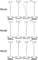
- Figs. 2A, 2B, and 2C are aberration charts respectively illustrating aberrations in a transmitted light path at the wide angle end, the intermediate area, and the telephoto end.
- Figs. 3A, 3B, and 3C are aberration charts respectively illustrating aberrations in a reflected light path at the wide angle end, the intermediate area, and the telephoto end.
- Fig. 1A and 1B are diagrams illustrating cross-sectional views at the wide angle end of the zoom lens according to the embodiment 1.
- Figs. 2A, 2B, and 2C are aberration charts respectively illustrating aberrations in a transmitted light path at the wide angle end, the intermediate area, and the telephoto end.
- Figs. 3A, 3B, and 3C are aberration charts respectively illustrating aberrations in a reflected light path at the wide angle end, the intermediate area, and the
- FIG. 1A illustrates a cross-sectional view of the zoom lens including the transmitted light path.
- Fig. 1A also illustrates loci of the plurality of lens groups moved when zooming is executed, and loci (moving directions) of sub-lens groups (a sub-lens group including 7th to 10th surfaces and a sub-lens group including 11th and 12th surfaces) moved when focusing is executed.
- Fig. 1B schematically illustrates a cross-sectional view of the zoom lens including the reflected light path.
- the zoom lens according to the embodiment 1 consists of a first lens group L1 having positive refractive power, a second lens group L2 having negative refractive power, a third lens group L3 having positive refractive power, a fourth lens group L4 having positive refractive power, an aperture stop SP, and fifth (final) lens groups L5' and L5 having positive refractive power, which are sequentially arranged from the object side to the image side.
- An image pickup surface of an image pickup element such as an image sensor is arranged on an image plane IP'.
- a light receiving unit for adding an auto-focusing (AF) function to the zoom lens i.e., a sensor used for AF
- AF auto-focusing
- another light receiving unit for adding a function other than the AF function e.g., a light-metering (photometry) function or a function of picking up an image in a plurality of wavelength regions
- a function other than the AF function e.g., a light-metering (photometry) function or a function of picking up an image in a plurality of wavelength regions
- the final lens group L5' includes a prism PR as a separation element which separates light into transmitted light and reflected light in order to branch a light path and a relay unit LR having positive refractive power which functions to form an image, which are sequentially arranged from the object side to the image side.
- the final lens group L5 includes a prism PR and a relay unit LA having positive refractive power which functions to form an image, which are sequentially arranged from the object side to the image side.
- a solid line represents spherical aberration in an e-line (wavelength: 594.6 nm), and a dashed two-dotted line represents spherical aberration in a g-line (wavelength: 435.8 nm).
- a solid line S represents astigmatism in a sagittal section
- a dashed line M represents astigmatism in a meridional section.
- Each of distortion charts illustrates distortion in the e-line.
- chromatic aberration charts illustrates magnification chromatic aberration in the g-line.
- Fno denotes an F-number
- ⁇ denotes a half-angle of view (°).
- FIG. 4A and 4B are diagrams illustrating cross-sectional views at the wide angle end of the zoom lens according to the embodiment 2.
- Figs. 5A, 5B, and 5C are aberration charts respectively illustrating aberrations in a transmitted light path at the wide angle end, the intermediate area, and the telephoto end.
- Figs. 6A, 6B, and 6C are aberration charts respectively illustrating aberrations in a reflected light path at the wide angle end, the intermediate area, and the telephoto end.
- Fig. 4A and 4B are diagrams illustrating cross-sectional views at the wide angle end of the zoom lens according to the embodiment 2.
- Figs. 5A, 5B, and 5C are aberration charts respectively illustrating aberrations in a transmitted light path at the wide angle end, the intermediate area, and the telephoto end.
- Figs. 6A, 6B, and 6C are aberration charts respectively illustrating aberrations in a reflected light path at the wide angle end, the intermediate area, and the
- FIG. 4A illustrates a cross-sectional view of the zoom lens including the transmitted light path.
- Fig. 4A also illustrates loci of the plurality of lens groups moved when zooming is executed, and a locus (moving direction) of a sub-lens group (a sub-lens group including 7th to 11th surfaces) moved when focusing is executed.
- Fig. 4B schematically illustrates a cross-sectional view of the zoom lens including the reflected light path.
- the zoom lens according to the embodiment 2 consists of a first lens group L1 having positive refractive power, a second lens group L2 having negative refractive power, a third lens group L3 having positive refractive power, an aperture stop SP, and fourth (final) lens groups L4' and L4 having positive refractive power, which are sequentially arranged from the object side to the image side.
- An image pickup surface of an image pickup element such as an image sensor is arranged on an image plane IP'.
- a light receiving unit i.e., a sensor
- another light receiving unit for adding the above-described function other than the AF function to the zoom lens can be arranged on the image plane IP.
- the first lens group L1 and the final lens groups L4' and L4 are not moved, the second lens group L2 is moved to the image side, and the third lens group L3 is moved.
- the final lens group L4' includes a prism PR as a separation element which separates light into transmitted light and reflected light in order to branch a light path and a relay unit LR having positive refractive power which functions to form an image, which are sequentially arranged from the object side to the image side.
- the final lens group L4 includes a prism PR and a relay unit LA having positive refractive power which functions to form an image, which are sequentially arranged from the object side to the image side.
- FIG. 7A and 7B are diagrams illustrating cross-sectional views at the wide angle end of the zoom lens according to the embodiment 3.
- Figs. 8A, 8B, and 8C are aberration charts respectively illustrating aberrations in a transmitted light path at the wide angle end, the intermediate area, and the telephoto end.
- Figs. 9A, 9B, and 9C are aberration charts respectively illustrating aberrations in a reflected light path at the wide angle end, the intermediate area, and the telephoto end.
- Fig. 7A and 7B are diagrams illustrating cross-sectional views at the wide angle end of the zoom lens according to the embodiment 3.
- Figs. 8A, 8B, and 8C are aberration charts respectively illustrating aberrations in a transmitted light path at the wide angle end, the intermediate area, and the telephoto end.
- Figs. 9A, 9B, and 9C are aberration charts respectively illustrating aberrations in a reflected light path at the wide angle end, the intermediate area, and the
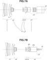
- FIG. 7A illustrates a cross-sectional view of the zoom lens including the transmitted light path.
- Fig. 7A also illustrates loci of the plurality of lens groups moved when zooming is executed, and a locus (moving direction) of a sub-lens group (a sub-lens group including 8th to 11th surfaces) moved when focusing is executed.
- Fig. 7B schematically illustrates a cross-sectional view of the zoom lens including the reflected light path.
- the zoom lens according to the embodiment 3 includes a first lens group L1 having positive refractive power, a second lens group L2 having negative refractive power, a third lens group L3 having negative refractive power, a fourth lens group L4 having positive refractive power, an aperture stop SP, and fifth (final) lens groups L5' and L5 having positive refractive power, which are sequentially arranged from the object side to the image side.
- An image pickup surface of an image pickup element such as an image sensor is arranged on an image plane IP'.
- a light receiving unit i.e., a sensor
- another light receiving unit for adding the above-described function other than the AF function to the zoom lens can be arranged on the image plane IP.
- the final lens group L5' includes a prism PR as a separation element which separates light into transmitted light and reflected light in order to branch a light path and a relay unit LR having positive refractive power which functions to form an image, which are sequentially arranged from the object side to the image side.
- the final lens group L5 includes a prism PR and a relay unit LA having positive refractive power which functions to form an image, which are sequentially arranged from the object side to the image side.
- FIG. 10A and 10B are diagrams illustrating cross-sectional views at the wide angle end of the zoom lens according to the embodiment 4.
- Figs. 11A, 11B, and 11C are aberration charts respectively illustrating aberrations in a reflected light path at the wide angle end, the intermediate area, and the telephoto end.
- Fig. 10A illustrates a cross-sectional view of the zoom lens including the transmitted light path.
- Fig. 10A also illustrates loci of the plurality of lens groups moved when zooming is executed, and loci (moving directions) of sub-lens groups (a sub-lens group including 7th to 10th surfaces and a sub-lens group including 11th and 12th surfaces) moved when focusing is executed.
- Fig. 10B schematically illustrates a cross-sectional view of the zoom lens including the reflected light path.
- the zoom lens according to the embodiment 4 includes a first lens group L1 having positive refractive power, a second lens group L2 having negative refractive power, a third lens group L3 having positive refractive power, a fourth lens group L4 having positive refractive power, an aperture stop SP, and fifth (final) lens groups L5' and L5 having positive refractive power, which are sequentially arranged from the object side to the image side.
- An image pickup surface of an image pickup element such as an image sensor is arranged on an image plane IP'.
- a light receiving unit for adding the AF function to the zoom lens i.e., a sensor used for auto-focusing
- an image plane IP an image plane of the zoom lens caused by the relay unit LA.
- the senor can be a phase-difference detection type sensor, although a type thereof is not limited thereto.
- another light receiving unit for adding the above-described function other than the AF function to the zoom lens can be arranged on the image plane IP.
- the final lens group L5' includes a prism PR as a separation element which separates light into transmitted light and reflected light in order to branch a light path and a relay unit LR having positive refractive power which functions to form an image, which are sequentially arranged from the object side to the image side.
- the final lens group L5 includes a prism PR and a relay unit LA having positive refractive power which functions to form an image, which are sequentially arranged from the object side to the image side.
- FIG. 12A and 12B are diagrams illustrating cross-sectional views at the wide angle end of the zoom lens according to the embodiment 5.
- Figs. 13A, 13B, and 13C are aberration charts respectively illustrating aberrations in a reflected light path at the wide angle end, the intermediate area, and the telephoto end.
- Figs. 5A, 5B, and 5C also illustrate aberrations in a transmitted light path at the wide angle end, the intermediate area, and the telephoto end according to the present embodiment.
- Fig. 12A illustrates a cross-sectional view of the zoom lens including the transmitted light path.
- Fig. 12A also illustrates loci of the plurality of lens groups moved when zooming is executed, and a locus (moving direction) of a sub-lens group (a sub-lens group including 7th to 11th surfaces) moved when focusing is executed.
- Fig. 12B schematically illustrates a cross-sectional view of the zoom lens including the reflected light path.
- the zoom lens according to the embodiment 5 includes a first lens group L1 having positive refractive power, a second lens group L2 having negative refractive power, a third lens group L3 having positive refractive power, an aperture stop SP, and fourth (final) lens groups L'4 and L4 having positive refractive power, which are sequentially arranged from the object side to the image side.
- An image pickup surface of an image pickup element such as an image sensor is arranged on an image plane IP'.
- a light receiving unit i.e., a sensor
- another light receiving unit for adding the above-described function other than the AF function to the zoom lens can be arranged on the image plane IP.
- the first lens group L1 and the final lens groups L4' and L4 are not moved, the second lens group L2 is moved to the image side, and the third lens group L3 is moved.
- the final lens group L4' includes a prism PR as a separation element which separates light into transmitted light and reflected light in order to branch a light path and a relay unit LR having positive refractive power which functions to form an image, which are sequentially arranged from the object side to the image side.
- the final lens group L4 includes a prism PR and a relay unit LA having positive refractive power which functions to form an image, which are sequentially arranged from the object side to the image side.
- r represents a curvature radius (mm) of a surface corresponding to a surface number (i-th surface)
- d represents a distance (a thickness of a lens or the air in mm) between the i-th surface and the (i + 1)-th surface.
- "(Variable)" described in a column of "d” indicates that a thickness of the air changes when zooming is executed, and a correspondence relationship between the thickness of the air and a focal length is described in an appended table.
- nd represents a refractive index of a material of the i-th optical member with respect to the d-line.
- vd represents an Abbe number of a material of the i-th optical member, which takes the d-line as a reference.
- vd nd ⁇ 1 / nF ⁇ nC
- nF, nd, and nC respectively represent refractive indexes of the F-line (wavelength: 486.1 nm), the d-line (wavelength: 587.6 nm), and the C-line (wavelength: 656.3 nm) of the Fraunhofer line.
- a half-angle of view (°) of the zoom lens is described, and a maximum image height corresponding to the half-angle of view is described as "Image Height”.
- a focal length of each lens group is described as the lens group data.
- a back focus (mm) is described as "BF”. The back focus is an air-equivalent length from an image-side surface of a lens having a refractive power (i.e., a final surface of the zoom lens) arranged closest to the image side of the zoom lens to a paraxial image plane on the optical axis.
- Total Length of Lens is also described.
- a total length of the zoom lens is a length obtained by adding a back focus to a distance from a forefront surface (i.e., an object-side surface of a lens arranged closest to the object side) of the zoom lens to the final surface of the zoom lens on the optical axis.
- H is a height of a point on the aspheric surface on an axis orthogonal to the optical axis, and a traveling direction of light on the optical axis is specified as a positive direction.
- R is a paraxial curvature radius of the aspheric surface
- K is a conic constant
- A2 to A16 are aspheric coefficients.
- a focal length described in each of the numerical embodiments 1 to 5 is a focal length with respect to the e-line (wavelength: 546.07 nm). Furthermore, values relating to the above-described conditional expressions 1 to 4 of the numerical embodiments 1 to 5 are described in a table 1.
- Embodiment 1 Embodiment 2 Embodiment 3 Embodiment 4 Embodiment 5 FwP/Fw 0.65 0.68 0.65 0.70 0.60 vLAG2 - vLAG3 49.22 65.52 49.22 35.19 65.52 PRL/L 0.44 0.49 0.49 0.45 0.46 (fLA ⁇ ⁇ LAG1R1) -1 0.57 0.53 0.63 0.59 0.60 Fw 8.50 7.20 7.80 8.50 7.20 FwP 5.512 4.875 5.070 5.910 4.320 vLAG2 81.54 94.66 81.54 70.23 94.66 vLAG3 32.32 29.14 32.32 35.04 29.14 PRL 40.88 40.88 40.88 43.00 38.00 L 93.84 83.25 82.99 95.84 83.25 fLA 36.60 29.70 34.10 37.40 26.20 ⁇ LAG1R1 0.048
Landscapes
- Physics & Mathematics (AREA)
- General Physics & Mathematics (AREA)
- Optics & Photonics (AREA)
- Lenses (AREA)
- Automatic Focus Adjustment (AREA)
- Lens Barrels (AREA)
Abstract
Description
- The present invention relates to a zoom lens and an image pickup apparatus.
- There has been known a zoom lens including a separation element for separating light in order to branch a light path. A light flux traveling along the branched light path can be used for an additional functions of the zoom lens such as an auto-focusing function.
-
Japanese Patent No. 5031475 - Because of the separation element, there is a possibility that lowering of optical performance and increase in size occur in the above-described zoom lens.
- Aspects of the present invention provide, for example, a zoom lens beneficial in a high optical performance and a small size.
- According to a first aspect of the present invention, there is provided a zoom lens as specified in
claims 1 to 14. According to a second aspect of the present invention, there is provided an image pickup apparatus as specified in claim 15. - Further features of the present invention will become apparent from the following description of embodiments with reference to the attached drawings.
-
-
Figs. 1A and 1B are diagrams illustrating cross-sectional views at a wide angle end of a zoom lens according to anembodiment 1. -
Figs. 2A, 2B, and 2C are aberration charts illustrating aberrations in a transmitted light path according to theembodiment 1 and an embodiment 4. -
Figs. 3A, 3B, and 3C are aberration charts illustrating aberrations in a reflected light path according to theembodiment 1. -
Figs. 4A and 4B are diagrams illustrating cross-sectional views at a wide angle end of a zoom lens according to an embodiment 2. -
Figs. 5A, 5B, and 5C are aberration charts illustrating aberrations in a transmitted light path according to the embodiment 2 and an embodiment 5. -
Figs. 6A, 6B, and 6C are aberration charts illustrating aberrations in a reflected light path according to the embodiment 2. -
Figs. 7A and 7B are diagrams illustrating cross-sectional views at a wide angle end of a zoom lens according to an embodiment 3. -
Figs. 8A, 8B, and 8C are aberration charts illustrating aberrations in a transmitted light path according to the embodiment 3. -
Figs. 9A, 9B, and 9C are aberration charts illustrating aberrations in a reflected light path according to the embodiment 3. -
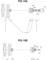
Figs. 10A and 10B are diagrams illustrating cross-sectional views at a wide angle end of a zoom lens according to the embodiment 4. -
Figs. 11A, 11B, and 11C are aberration charts illustrating aberrations in a reflected light path according to the embodiment 4. -
Figs. 12A and 12B are diagrams illustrating cross-sectional views at a wide angle end of a zoom lens according to the embodiment 5. -
Figs. 13A, 13B, and 13C are aberration charts illustrating aberrations in a reflected light path according to the embodiment 5. -
Figs. 14A and 14B are diagrams illustrating examples of a configuration of a zoom lens apparatus. -
Fig. 15 is a diagram illustrating an example of a configuration of an image pickup apparatus. - Hereinafter, embodiments according to the present invention will be described with reference to the appended drawings. In principle, unless otherwise noted, common reference numerals are applied to members common in all of the appended drawings illustrating the embodiments, and repetitive descriptions thereof will be omitted.
-
Figs. 14A and 14B are diagrams illustrating examples of a configuration of a zoom lens apparatus. InFig. 14A , through a separation element PR which separates incident light (light flux) into transmitted light and reflected light, a light path is branched into a path (i.e., straight light path or transmitted light path) of light traveling straight after passing through the separation element PR and a path (i.e., reflected light path) of light traveling after being reflected by the separation element PR. InFig. 14B , the reflected light path is schematically developed on a straight line. Each of the embodiments according to the present embodiment describes a numerical embodiment of an optical system including the reflected light path. As illustrated inFig. 14B , a focusing unit (i.e., a first lens group) and a scaling unit (i.e., a plurality of lens groups moved when zooming is executed), and an aperture stop SP are sequentially arranged from an object side to an image side. The separation element PR is arranged next to the aperture stop SP on the image side. In the reflected light path, light passes through the separation element PR along a light path having a long light path length PRL, and forms an image on an image plane IP via a relay unit LA (also called "lens group LA"). There is a possibility that a size of the relay unit LA is increased due to the long light path length PRL. - The present embodiment takes into consideration an issue of a large-sized relay unit. Herein, Fw represents a focal length at a wide angle end of an optical system (zoom lens) including the transmitted light path on which the relay unit LR is arranged, and FwP represents a focal length at the wide angle end of the optical system including the reflected light path on which the relay unit LA is arranged. For the sake of downsizing (i.e., reduction in diameter) of the relay unit LA and improvement in the optical performance of the zoom lens, it is preferable that the following condition (a conditional expression, i.e., an inequality) be satisfied.


- Further, it is more preferable that the following condition be satisfied.

- Still further, it is even more preferable that the following condition be satisfied.

- Herein, it is preferable that the relay unit LA include a lens LAG1 having positive refractive power and a cemented lens LAG3A consisting of a positive lens and a negative lens cemented together, which are sequentially arranged from the object side close to the separation element PR to the image side. A height of an off-axis light flux incident on the relay unit LA becomes high due to the long light path length PRL of a light path within the separation element PR which the off-axis light flux passes through. In this case, by arranging the positive lens LAG1, a size of a lens group arranged posterior to the positive lens LAG1 can be reduced. Further, chromatic aberration occurring in the above-described configuration can be reduced by arranging the cemented lens LAG3A.
- Further, it is preferable that a lens group having positive refractive power be arranged next to the aperture stop SP on the object side and moved to the object side when zooming is executed from the wide angle end to the telephoto end. The above-described configuration is advantageous to a zoom lens having a high zoom ratio.
- Furthermore, it is preferable that the following conditional expression be satisfied where an Abbe number of the positive lens included in the cemented lens LAG3A is vLAG2, and an Abbe number of the positive lens included in the cemented lens LAG3A is vLAG3.

- If a condition with respect to a lower limit value of the conditional expression (2) is not satisfied, chromatic aberration occurring in the lens LAG1 is not corrected sufficiently. If a condition with respect to an upper limit value of the conditional expression (2) is not satisfied, chromatic aberration occurring in the lens LAG1 is corrected excessively.
- It is more preferable that the following condition be satisfied.

- Furthermore, it is more preferable that the following condition be satisfied.

- Further, it is preferable that the separation element PR (also referred to as a splitting element) include an incident surface and a separation surface for separating (splitting) light incident on the incident surface into the above-described reflected light and the transmitted light, and reflect (totally reflect) the reflected light from the separation surface with the incident surface to cause the reflected light to be output from the separation element PR. With this configuration, a total length of the optical system including the relay unit LR is shortened, so that it is possible to provide a zoom lens advantageous in terms of downsizing. Further, it is preferable that the following conditional expression be satisfied where L is a distance from the aperture stop SP to the image plane IP (an image plane of the zoom lens caused by the relay unit LA), and PRL is a light path length of the separation element PR on the reflected light path (a light path of the zoom lens via the relay unit LA).

- If a condition with respect to a lower limit value of the conditional expression (3) is not satisfied, a light path length of the transmitted light path in the separation element PR is lengthened, so that a total length of the zoom lens is increased excessively. If a condition with respect to an upper limit value of the conditional expression (3) is not satisfied, a light path length of the reflected light path in the separation element PR is lengthened, so that a diameter of the relay unit LA is increased excessively. It is more preferable that the following condition be satisfied.

- Furthermore, it is more preferable that the following condition be satisfied.

- Further, in the zoom lens according to the present embodiment, it is preferable that the relay unit LA include a lens LAG1 having positive refractive power arranged closest to the object side and a lens LAGN. Then, it is preferable that the following conditional expression be satisfied where fLA is a focal length of the relay unit LA and ϕLAG1R1 is refractive power of a surface LAG1R1 of the lens LAG1 on the object side.

- If a condition with respect to a lower limit value of the conditional expression (4) is not satisfied, aberrations (e.g., spherical aberration and on-axis chromatic aberration) occurring on the surface G1R1 become excessively large, so that it will be difficult to acquire a zoom lens having high optical performance. If a condition with respect to an upper limit value of the conditional expression (4) is not satisfied, effective diameters of surfaces which follow the surface G1R1 become excessively large, so that it will be difficult to acquire a small-sized zoom lens. It is more preferable that the following condition be satisfied.

- Further, it is more preferable that the following condition be satisfied.

-
Fig. 15 is a diagram illustrating an example of a configuration of animage pickup apparatus 125. InFig. 15 , azoom lens 101 is any one of the zoom lenses according to theembodiments 1 to 5. Animage pickup apparatus 125 includes a cameramain body 124. Thezoom lens 101 is attachable to and detachable from the cameramain body 124. Theimage pickup apparatus 125 includes the cameramain body 124 and thezoom lens 101 mounted on the cameramain body 124. Thezoom lens 101 includes a first lens group F, two or more lens groups LZ which are moved when zooming (scaling) is executed, and a final lens group R. At least part of the first lens group F is moved on an optical axis in order to execute focusing (bring an object into focus). In the present embodiment, the first lens group F includes a second sub-lens group which is moved on the optical axis in order to execute focusing and a first sub-lens group and a third sub-lens group which are not moved when focusing is executed, although a configuration thereof is not limited thereto. - The two or more lens groups LZ for executing zooming are moved on the optical axis when zooming is executed. The
zoom lens 101 also includes an aperture stop SP. The final lens group R may include a sub-lens group which can be inserted and removed to/from the light path. A range of the focal length of thezoom lens 101 can be changed by insertion and/or removal of the sub-lens group. The second sub-lens group 1b and the two or more lens groups LZ for executing zooming are respectively driven in the optical axis direction by drivingmechanisms mechanisms mechanisms Detection units 119 to 121 respectively detect a position of the second sub-lens group 1b on the optical axis, positions of the two or more lens groups LZ for executing zooming on the optical axis, and an opening size of the aperture stop SP. Each of thedetection units 119 to 121 is configured of constituent elements such as an encoder, a potentiometer, and a photosensor. The cameramain body 124 includes aglass block 109 which includes an optical filter and an image pickup element (photoelectric conversion element) 110 for picking up an object image formed by thezoom lens 101. Theimage sensor 110 is configured of a charge-coupled device (CCD) sensor or a complementary metal-oxide semiconductor (CMOS) sensor. A central processing unit (CPU) 111 operates as a processing unit (control unit) of the cameramain body 124, and aCPU 122 operates as a processing unit (control unit) of thezoom lens 101. As described above, by mounting the zoom lens according to the above-described embodiment on the camera main body, it is possible to provide a functional image pickup apparatus including the zoom lens having the above-described advantageous effect. - A zoom lens according to a (numerical)
embodiment 1 will be described with reference toFigs. 1A and 1B ,Figs. 2A to 2C , andFigs. 3A to 3C .Figs. 1A and 1B are diagrams illustrating cross-sectional views at the wide angle end of the zoom lens according to theembodiment 1.Figs. 2A, 2B, and 2C are aberration charts respectively illustrating aberrations in a transmitted light path at the wide angle end, the intermediate area, and the telephoto end.Figs. 3A, 3B, and 3C are aberration charts respectively illustrating aberrations in a reflected light path at the wide angle end, the intermediate area, and the telephoto end.Fig. 1A illustrates a cross-sectional view of the zoom lens including the transmitted light path.Fig. 1A also illustrates loci of the plurality of lens groups moved when zooming is executed, and loci (moving directions) of sub-lens groups (a sub-lens group including 7th to 10th surfaces and a sub-lens group including 11th and 12th surfaces) moved when focusing is executed.Fig. 1B schematically illustrates a cross-sectional view of the zoom lens including the reflected light path. The zoom lens according to theembodiment 1 consists of a first lens group L1 having positive refractive power, a second lens group L2 having negative refractive power, a third lens group L3 having positive refractive power, a fourth lens group L4 having positive refractive power, an aperture stop SP, and fifth (final) lens groups L5' and L5 having positive refractive power, which are sequentially arranged from the object side to the image side. An image pickup surface of an image pickup element such as an image sensor is arranged on an image plane IP'. A light receiving unit for adding an auto-focusing (AF) function to the zoom lens (i.e., a sensor used for AF) is arranged on an image plane IP. Further, instead of or in addition to the above-described light receiving unit, another light receiving unit for adding a function other than the AF function (e.g., a light-metering (photometry) function or a function of picking up an image in a plurality of wavelength regions) to the zoom lens can be arranged on the image plane IP. - When zooming is executed from the wide angle end to the telephoto end, the first lens group L1 and the final lens groups L5' and L5 are not moved, the second lens group L2 is moved to the image side, and the third lens group L3 and the fourth lens group L4 are moved. The final lens group L5' includes a prism PR as a separation element which separates light into transmitted light and reflected light in order to branch a light path and a relay unit LR having positive refractive power which functions to form an image, which are sequentially arranged from the object side to the image side. The final lens group L5 includes a prism PR and a relay unit LA having positive refractive power which functions to form an image, which are sequentially arranged from the object side to the image side.
- Next,
Figs. 2A to 2C andFigs. 3A to 3C will be described. In each of spherical aberration charts, a solid line represents spherical aberration in an e-line (wavelength: 594.6 nm), and a dashed two-dotted line represents spherical aberration in a g-line (wavelength: 435.8 nm). In each of astigmatism charts, a solid line S represents astigmatism in a sagittal section, and a dashed line M represents astigmatism in a meridional section. Each of distortion charts illustrates distortion in the e-line. Each of chromatic aberration charts illustrates magnification chromatic aberration in the g-line. Further, inFigs. 2A to 2C andFigs. 3A to 3C , Fno denotes an F-number, and ω denotes a half-angle of view (°). The above descriptions of the aberration charts are also applicable to the other embodiments. - A zoom lens according to a (numerical) embodiment 2 will be described with reference to
Figs. 4A and 4B ,Figs. 5A to 5C , andFigs. 6A to 6C .Figs. 4A and 4B are diagrams illustrating cross-sectional views at the wide angle end of the zoom lens according to the embodiment 2.Figs. 5A, 5B, and 5C are aberration charts respectively illustrating aberrations in a transmitted light path at the wide angle end, the intermediate area, and the telephoto end.Figs. 6A, 6B, and 6C are aberration charts respectively illustrating aberrations in a reflected light path at the wide angle end, the intermediate area, and the telephoto end.Fig. 4A illustrates a cross-sectional view of the zoom lens including the transmitted light path.Fig. 4A also illustrates loci of the plurality of lens groups moved when zooming is executed, and a locus (moving direction) of a sub-lens group (a sub-lens group including 7th to 11th surfaces) moved when focusing is executed.Fig. 4B schematically illustrates a cross-sectional view of the zoom lens including the reflected light path. The zoom lens according to the embodiment 2 consists of a first lens group L1 having positive refractive power, a second lens group L2 having negative refractive power, a third lens group L3 having positive refractive power, an aperture stop SP, and fourth (final) lens groups L4' and L4 having positive refractive power, which are sequentially arranged from the object side to the image side. An image pickup surface of an image pickup element such as an image sensor is arranged on an image plane IP'. A light receiving unit (i.e., a sensor) for adding the AF function to the zoom lens is arranged on an image plane IP. Further, instead of or in addition to the light receiving unit, another light receiving unit for adding the above-described function other than the AF function to the zoom lens can be arranged on the image plane IP. - When zooming is executed from the wide angle end to the telephoto end, the first lens group L1 and the final lens groups L4' and L4 are not moved, the second lens group L2 is moved to the image side, and the third lens group L3 is moved.
- The final lens group L4' includes a prism PR as a separation element which separates light into transmitted light and reflected light in order to branch a light path and a relay unit LR having positive refractive power which functions to form an image, which are sequentially arranged from the object side to the image side. The final lens group L4 includes a prism PR and a relay unit LA having positive refractive power which functions to form an image, which are sequentially arranged from the object side to the image side.
- A zoom lens according to a (numerical) embodiment 3 will be described with reference to
Figs. 7A and 7B ,Figs. 8A to 8C , andFigs. 9A to 9C .Figs. 7A and 7B are diagrams illustrating cross-sectional views at the wide angle end of the zoom lens according to the embodiment 3.Figs. 8A, 8B, and 8C are aberration charts respectively illustrating aberrations in a transmitted light path at the wide angle end, the intermediate area, and the telephoto end.Figs. 9A, 9B, and 9C are aberration charts respectively illustrating aberrations in a reflected light path at the wide angle end, the intermediate area, and the telephoto end.Fig. 7A illustrates a cross-sectional view of the zoom lens including the transmitted light path.Fig. 7A also illustrates loci of the plurality of lens groups moved when zooming is executed, and a locus (moving direction) of a sub-lens group (a sub-lens group including 8th to 11th surfaces) moved when focusing is executed.Fig. 7B schematically illustrates a cross-sectional view of the zoom lens including the reflected light path. The zoom lens according to the embodiment 3 includes a first lens group L1 having positive refractive power, a second lens group L2 having negative refractive power, a third lens group L3 having negative refractive power, a fourth lens group L4 having positive refractive power, an aperture stop SP, and fifth (final) lens groups L5' and L5 having positive refractive power, which are sequentially arranged from the object side to the image side. An image pickup surface of an image pickup element such as an image sensor is arranged on an image plane IP'. A light receiving unit (i.e., a sensor) for adding the AF function to the zoom lens is arranged on an image plane IP. Further, instead of or in addition to the light receiving unit, another light receiving unit for adding the above-described function other than the AF function to the zoom lens can be arranged on the image plane IP. - When zooming is executed from the wide angle end to the telephoto end, the first lens group L1 and the final lens groups L5' and L5 are not moved, the second lens group L2 is moved to the image side, and the third lens group L3 and the fourth lens group L4 are moved. The final lens group L5' includes a prism PR as a separation element which separates light into transmitted light and reflected light in order to branch a light path and a relay unit LR having positive refractive power which functions to form an image, which are sequentially arranged from the object side to the image side. The final lens group L5 includes a prism PR and a relay unit LA having positive refractive power which functions to form an image, which are sequentially arranged from the object side to the image side.
- A zoom lens according to a (numerical) embodiment 4 will be described with reference to
Figs. 10A and 10B andFigs. 11A to 11C .Figs. 10A and 10B are diagrams illustrating cross-sectional views at the wide angle end of the zoom lens according to the embodiment 4.Figs. 11A, 11B, and 11C are aberration charts respectively illustrating aberrations in a reflected light path at the wide angle end, the intermediate area, and the telephoto end. - The above-described aberration charts in
Figs. 2A, 2B, and 2C also illustrate aberrations in a transmitted light path at the wide angle end, the intermediate area, and the telephoto end according to the present embodiment.Fig. 10A illustrates a cross-sectional view of the zoom lens including the transmitted light path.Fig. 10A also illustrates loci of the plurality of lens groups moved when zooming is executed, and loci (moving directions) of sub-lens groups (a sub-lens group including 7th to 10th surfaces and a sub-lens group including 11th and 12th surfaces) moved when focusing is executed.Fig. 10B schematically illustrates a cross-sectional view of the zoom lens including the reflected light path. The zoom lens according to the embodiment 4 includes a first lens group L1 having positive refractive power, a second lens group L2 having negative refractive power, a third lens group L3 having positive refractive power, a fourth lens group L4 having positive refractive power, an aperture stop SP, and fifth (final) lens groups L5' and L5 having positive refractive power, which are sequentially arranged from the object side to the image side. An image pickup surface of an image pickup element such as an image sensor is arranged on an image plane IP'. A light receiving unit for adding the AF function to the zoom lens (i.e., a sensor used for auto-focusing) is arranged on an image plane IP (an image plane of the zoom lens caused by the relay unit LA). In addition, the sensor can be a phase-difference detection type sensor, although a type thereof is not limited thereto. Further, instead of or in addition to the light receiving unit, another light receiving unit for adding the above-described function other than the AF function to the zoom lens can be arranged on the image plane IP. - When zooming is executed from the wide angle end to the telephoto end, the first lens group L1 and the final lens groups L5' and L5 are not moved, the second lens group L2 is moved to the image side, and the third lens group L3 and the fourth lens group L4 are moved. The final lens group L5' includes a prism PR as a separation element which separates light into transmitted light and reflected light in order to branch a light path and a relay unit LR having positive refractive power which functions to form an image, which are sequentially arranged from the object side to the image side. The final lens group L5 includes a prism PR and a relay unit LA having positive refractive power which functions to form an image, which are sequentially arranged from the object side to the image side.
- A zoom lens according to a (numerical) embodiment 5 will be described with reference to
Figs. 12A and 12B andFigs. 13A to 13C .Figs. 12A and 12B are diagrams illustrating cross-sectional views at the wide angle end of the zoom lens according to the embodiment 5.Figs. 13A, 13B, and 13C are aberration charts respectively illustrating aberrations in a reflected light path at the wide angle end, the intermediate area, and the telephoto end. - The above-described aberration charts in
Figs. 5A, 5B, and 5C also illustrate aberrations in a transmitted light path at the wide angle end, the intermediate area, and the telephoto end according to the present embodiment.Fig. 12A illustrates a cross-sectional view of the zoom lens including the transmitted light path.Fig. 12A also illustrates loci of the plurality of lens groups moved when zooming is executed, and a locus (moving direction) of a sub-lens group (a sub-lens group including 7th to 11th surfaces) moved when focusing is executed. -
Fig. 12B schematically illustrates a cross-sectional view of the zoom lens including the reflected light path. The zoom lens according to the embodiment 5 includes a first lens group L1 having positive refractive power, a second lens group L2 having negative refractive power, a third lens group L3 having positive refractive power, an aperture stop SP, and fourth (final) lens groups L'4 and L4 having positive refractive power, which are sequentially arranged from the object side to the image side. An image pickup surface of an image pickup element such as an image sensor is arranged on an image plane IP'. A light receiving unit (i.e., a sensor) for adding the AF function to the zoom lens is arranged on an image plane IP. Further, instead of or in addition to the light receiving unit, another light receiving unit for adding the above-described function other than the AF function to the zoom lens can be arranged on the image plane IP. - When zooming is executed from the wide angle end to the telephoto end, the first lens group L1 and the final lens groups L4' and L4 are not moved, the second lens group L2 is moved to the image side, and the third lens group L3 is moved.
- The final lens group L4' includes a prism PR as a separation element which separates light into transmitted light and reflected light in order to branch a light path and a relay unit LR having positive refractive power which functions to form an image, which are sequentially arranged from the object side to the image side. The final lens group L4 includes a prism PR and a relay unit LA having positive refractive power which functions to form an image, which are sequentially arranged from the object side to the image side.
- Hereinafter,
numerical embodiments 1 to 5 corresponding to the above-describedembodiments 1 to 5 will be described. In each of thenumerical embodiments 1 to 5, r represents a curvature radius (mm) of a surface corresponding to a surface number (i-th surface), d represents a distance (a thickness of a lens or the air in mm) between the i-th surface and the (i + 1)-th surface. Further, "(Variable)" described in a column of "d" indicates that a thickness of the air changes when zooming is executed, and a correspondence relationship between the thickness of the air and a focal length is described in an appended table. nd represents a refractive index of a material of the i-th optical member with respect to the d-line. vd represents an Abbe number of a material of the i-th optical member, which takes the d-line as a reference. - In addition, the Abbe number vd is defined by the following formula (A).

- Herein, nF, nd, and nC respectively represent refractive indexes of the F-line (wavelength: 486.1 nm), the d-line (wavelength: 587.6 nm), and the C-line (wavelength: 656.3 nm) of the Fraunhofer line.
- Further, in each of the
numerical embodiments 1 to 5, a half-angle of view (°) of the zoom lens is described, and a maximum image height corresponding to the half-angle of view is described as "Image Height". Furthermore, a focal length of each lens group is described as the lens group data. Furthermore, a back focus (mm) is described as "BF". The back focus is an air-equivalent length from an image-side surface of a lens having a refractive power (i.e., a final surface of the zoom lens) arranged closest to the image side of the zoom lens to a paraxial image plane on the optical axis. Further, "Total Length of Lens" is also described. A total length of the zoom lens is a length obtained by adding a back focus to a distance from a forefront surface (i.e., an object-side surface of a lens arranged closest to the object side) of the zoom lens to the final surface of the zoom lens on the optical axis. - Further, "*" added to a surface number indicates that a surface corresponding to that surface number is an aspheric surface. H is a height of a point on the aspheric surface on an axis orthogonal to the optical axis, and a traveling direction of light on the optical axis is specified as a positive direction. Furthermore, R is a paraxial curvature radius of the aspheric surface, K is a conic constant, and A2 to A16 are aspheric coefficients. Then, a shift amount X from a reference spherical surface of the point at the height H on an axis parallel to the optical axis is expressed by the following
formula 1.
- In each of the
numerical embodiments 1 to 5, "e±X" in each of the conic constants and the aspheric coefficients represents "×10±x". - Further, a focal length described in each of the
numerical embodiments 1 to 5 is a focal length with respect to the e-line (wavelength: 546.07 nm). Furthermore, values relating to the above-describedconditional expressions 1 to 4 of thenumerical embodiments 1 to 5 are described in a table 1. -
- Unit: mm
- Surface Data
- The 13th Surface
- K = 1.99852e+000
- A4 = 1.15677e-006
- A6 = -2.75064e-008
- A8 = -3.06848e-010
- A10 = 9.10515e-013
- A12 = 3.28486e-015
- A14 = 1.35261e-018
- A16 = 5.54400e-022
- A3 = 2.74335e-007
- A5 = 9.95673e-008
- A7 = 4.02226e-009
- A9 = 6.12079e-012
- A11 = -8.52506e-014
- A13 = -6.85632e-017
- A15 = -3.84859e-020
- The 21st Surface
- K = 1.21093e+001
- A4 = 2.82183e-007
- A6 = -5.59441e-011
- A8 = -2.00796e-014
- A10 = 9.78964e-017
- A12 = -6.30815e-020
- A14 = 1.70834e-023
- A16 = -4.73901e-027
- A3 = -2.90901e-008
- A5 = 1.58196e-009
- A7 = 1.10620e-012
- A9 = -1.50730e-015
- A11 = 5.86871e-020
- A13 = 1.04584e-022
- A15 = 1.44467e-025
- The 30th Surface
- K = -2.23400e+002
- A4 = 2.77687e-007
- A6 = 4.69555e-010
- A8 = 1.39733e-013
- A10 = -2.98156e-016
- A12 = 4.58582e-019
- A14 = -2.25443e-022
- A16 = 5.80568e-026
- A3 = 1.70768e-007
- A5 = -5.73181e-009
- A7 = -1.36230e-011
- A9 = 7.92918e-015
- A11 = -8.14405e-018
- A13 = 2.06016e-021
- A15 = -8.57551e-025
- Various Data
- Zoom Ratio: 120.00
-
Group Beginning Surface Focal Distance 1 1 251.50 2 13 -24.07 3 20 134.62 4 26 112.37 5 31 35.15 -
- Unit: mm
- Surface Data
-
Wide Angle End Intermediate Area Telephoto End Focal Distance 5.51 64.85 661.44 F-Number 3.80 3.80 3.79 Angle of View 32.97 3.16 0.31 Image Height 3.58 3.58 3.58 Total Length of Lens 609.84 609.84 609.84 BF 7.73 7.73 7.73 d12 3.47 154.53 194.08 d19 289.33 96.92 2.00 d25 4.21 10.30 4.50 d30 2.99 38.24 99.42 d47 7.73 7.73 7.73 -
Group Beginning Surface Focal Distance 5 31 47.42 -
- Unit: mm
- Surface Data
- The 28th Surface
- K = 0.00000e+000
- A4 = 2.32112e-007
- A6 = 2.35378e-010
- A8 = -2.98860e-013
- A10 = 1.74212e-016
- Various Data
- Zoom Ratio: 18.50
-
Group Beginning Surface Focal Distance 1 1 113.04 2 18 -29.50 3 27 49.00 4 37 30.04 -
- Unit: mm
- Surface Data
-
Group Beginning Surface Focal Distance 4 37 38.17 -
- Unit: mm
- Surface Data
- The 23rd Surface
- K = -6.95534e-001
- A4 = 1.29096e-006
- A6 = 3.74923e-010
- A8 = 5.46374e-012
- A10 = -1.71339e-014
- A12 = 9.53627e-018
- Various Data
- Zoom Ratio: 21.81
-
Group Beginning Surface Focal Distance 1 1 71.50 2 12 -13.80 3 19 -57.00 4 22 48.00 5 24 51.04 -
- Unit: mm
- Surface Data
-
Group Beginning Surface Focal Distance 5 24 32.97 -
- Unit: mm
- Surface Data
- The 13th Surface
- K = 1.99852e+000
- A4 = 1.15677e-006
- A6 = -2.75064e-008
- A8 = -3.06848e-010
- A10 = 9.10515e-013
- A12 = 3.28486e-015
- A14 = 1.35261e-018
- A16 = 5.54400e-022
- A3 = 2.74335e-007
- A5 = 9.95673e-008
- A7 = 4.02226e-009
- A9 = 6.12079e-012
- A11 = -8.52506e-014
- A13 = -6.85632e-017
- A15 = -3.84859e-020
- The 21st Surface
- K = 1.21093e+001
- A4 = 2.82183e-007
- A6 = -5.59441e-011
- A8 = -2.00796e-014
- A10 = 9.78964e-017
- A12 = -6.30815e-020
- A14 = 1.70834e-023
- A16 = -4.73901e-027
- A3 = -2.90901e-008
- A5 = 1.58196e-009
- A7 = 1.10620e-012
- A9 = -1.50730e-015
- A11 = 5.86871e-020
- A13 = 1.04584e-022
- A15 = 1.44467e-025
- The 30th Surface
- K = -2.23400e+002
- A4 = 2.77687e-007
- A6 = 4.69555e-010
- A8 = 1.39733e-013
- A10 = -2.98156e-016
- A12 = 4.58582e-019
- A14 = -2.25443e-022
- A16 = 5.80568e-026
- A3 = 1.70768e-007
- A5 = -5.73181e-009
- A7 = -1.36230e-011
- A9 = 7.92918e-015
- A11 = -8.14405e-018
- A13 = 2.06016e-021
- A15 = -8.57551e-025
- Various Data
- Zoom Ratio: 120.00
-
Group Beginning Surface Focal Distance 1 1 251.50 2 13 -24.07 3 20 134.62 4 26 112.37 5 31 35.15 -
- Unit: mm
- Surface Data
-
Group Beginning Surface Focal Distance 5 31 43.38 -
- Unit: mm
- Surface Data
- The 28th Surface
- K = 0.00000e+000
- A4 = 2.32112e-007
- A6 = 2.35378e-010
- A8 = -2.98860e-013
- A10 = 1.74212e-016
- Various Data
- Zoom Ratio: 18.50
-
Group Beginning Surface Focal Distance 1 1 113.04 2 18 -29.50 3 27 49.00 4 37 30.04 -
- Unit: mm
- Surface Data
-
Group Beginning Surface Focal Distance 4 37 27.71 [Table 1] Embodiment 1Embodiment 2 Embodiment 3 Embodiment 4 Embodiment 5 FwP/Fw 0.65 0.68 0.65 0.70 0.60 vLAG2 - vLAG3 49.22 65.52 49.22 35.19 65.52 PRL/L 0.44 0.49 0.49 0.45 0.46 (fLA × ϕ LAG1R1)-1 0.57 0.53 0.63 0.59 0.60 Fw 8.50 7.20 7.80 8.50 7.20 FwP 5.512 4.875 5.070 5.910 4.320 vLAG2 81.54 94.66 81.54 70.23 94.66 vLAG3 32.32 29.14 32.32 35.04 29.14 PRL 40.88 40.88 40.88 43.00 38.00 L 93.84 83.25 82.99 95.84 83.25 fLA 36.60 29.70 34.10 37.40 26.20 ϕLAG1R1 0.048 0.063 0.047 0.046 0.063 - Although the preferred embodiments according to the present invention has been described as the above, the present invention is not limited to these embodiments, and various modifications and changes are possible within the scope of the present invention.
- According to the aspect of the present invention, for example, it is possible to provide a zoom lens advantageous in terms of miniaturization.
- While the present invention has been described with reference to embodiments, it is to be understood that the invention is not limited to the disclosed embodiments, but is defined by the scope of the following claims.
| Surface Number | r | d | nd | vd |
| 1 | -2942.188 | 6.00 | 1.83481 | 42.7 |
| 2 | 335.459 | 1.80 | ||
| 3 | 335.066 | 23.71 | 1.43387 | 95.1 |
| 4 | -1057.929 | 0.20 | ||
| 5 | 525.299 | 14.68 | 1.43387 | 95.1 |
| 6 | -2449.905 | 25.25 | ||
| 7 | 377.042 | 20.53 | 1.43387 | 95.1 |
| 8 | -1365.497 | 0.25 | ||
| 9 | 306.954 | 16.16 | 1.43387 | 95.1 |
| 10 | 1716.232 | 1.50 | ||
| 11 | 188.244 | 16.19 | 1.43875 | 94.7 |
| 12 | 408.078 | (Variable) | ||
| 13* | -532.824 | 2.20 | 2.00330 | 28.3 |
| 14 | 38.132 | 11.72 | ||
| 15 | -44.546 | 1.45 | 1.74320 | 49.3 |
| 16 | 72.565 | 9.77 | 1.89286 | 20.4 |
| 17 | -46.484 | 1.63 | ||
| 18 | -41.758 | 2.00 | 1.88300 | 40.8 |
| 19 | -152.608 | (Variable) | ||
| 20 | 152.336 | 11.49 | 1.72916 | 54.7 |
| 21∗ | -265.715 | 6.62 | ||
| 22 | 139.888 | 13.50 | 1.43875 | 94.7 |
| 23 | -246.304 | 0.50 | ||
| 24 | 264.094 | 2.60 | 1.85478 | 24.8 |
| 25 | 97.106 | (Variable) | ||
| 26 | 86.506 | 15.39 | 1.49700 | 81.5 |
| 27 | -236.969 | 0.50 | ||
| 28 | 415.877 | 2.50 | 1.80518 | 25.4 |
| 29 | 139.362 | 7.85 | 1.60311 | 60.6 |
| 30* | -764.201 | (Variable) | ||
| 31 (Aperture) | ∞ | 5.46 | ||
| 32 | -100.588 | 1.40 | 1.88300 | 40.8 |
| 33 | 50.285 | 1.36 | ||
| 34 | 40.817 | 3.60 | 1.92286 | 18.9 |
| 35 | 96.042 | 4.19 | ||
| 36 | -79.866 | 1.70 | 1.80400 | 46.5 |
| 37 | -114.439 | 5.00 | ||
| 38 | ∞ | 17.45 | 1.83481 | 42.7 |
| 39 | ∞ | 1.50 | ||
| 40 | 471.053 | 2.00 | 2.00100 | 29.1 |
| 41 | 61.204 | 5.25 | ||
| 42 | -154.723 | 1.50 | 1.88300 | 40.8 |
| 43 | 48.981 | 6.45 | 1.84666 | 23.8 |
| 44 | -66.247 | 0.20 | ||
| 45 | -246.690 | 9.17 | 1.43875 | 94.7 |
| 46 | -32.301 | 0.20 | ||
| 47 | -62.829 | 8.38 | 1.81600 | 46.6 |
| 48 | -21.384 | 1.50 | 2.00100 | 29.1 |
| 49 | -126.267 | 8.68 | ||
| 50 | -1310.821 | 1.40 | 1.83481 | 42.7 |
| 51 | 36.358 | 7.90 | 1.80518 | 25.4 |
| 52 | -196.957 | 0.28 | ||
| 53 | 146.796 | 7.95 | 1.48749 | 70.2 |
| 54 | -38.232 | 1.62 | 2.00100 | 29.1 |
| 55 | -82.855 | 0.99 | ||
| 56 | -132.295 | 5.94 | 1.60562 | 43.7 |
| 57 | -40.442 | 0.22 | ||
| 58 | 109.076 | 6.96 | 1.64000 | 60.1 |
| 59 | -47.080 | 1.62 | 2.00100 | 29.1 |
| 60 | -140.064 | 9.82 | ||
| 61 | ∞ | 33.00 | 1.60859 | 46.4 |
| 62 | ∞ | 13.20 | 1.51633 | 64.2 |
| 63 | ∞ | (Variable) | ||
| Image Plane | ∞ |
| Wide Angle End | Intermediate Area | Telephoto End | |
| Focal Distance | 8.50 | 100.01 | 1020.12 |
| F-Number | 1.75 | 1.75 | 5.25 |
| Angle of View | 32.90 | 3.15 | 0.31 |
| Image Height | 5.50 | 5.50 | 5.50 |
| Total Length of Lens | 687.65 | 687.65 | 687.65 |
| BF | 51.79 | 51.79 | 51.79 |
| d12 | 3.47 | 154.53 | 194.08 |
| d19 | 289.33 | 96.92 | 2.00 |
| d25 | 4.21 | 10.30 | 4.50 |
| d30 | 2.99 | 38.24 | 99.42 |
| d63 | 12.80 | 12.80 | 12.80 |
| Surface Number | r | d | nd | vd |
| 38 | ∞ | 40.88 | 1.83481 | 42.7 |
| 39 | ∞ | 1.47 | ||
| 40 | 10.377 | 5.59 | 1.49700 | 81.5 |
| 41 | -1045.456 | 0.20 | ||
| 42 | 9.920 | 4.80 | 1.49700 | 81.5 |
| 43 | -15.113 | 1.50 | 1.95375 | 32.3 |
| 44 | 6.432 | 3.02 | ||
| 45 | 15.953 | 5.24 | 1.85025 | 30.1 |
| 46 | -5.936 | 0.70 | 1.81600 | 46.6 |
| 47 | 109.674 | (Variable) | ||
| Image Plane | ∞ |
| Surface Number | r | d | nd | vd |
| 1 | 335.346 | 4.70 | 1.77250 | 49.6 |
| 2 | 100.786 | 37.33 | ||
| 3 | -190.279 | 4.50 | 1.77250 | 49.6 |
| 4 | 3222.942 | 0.15 | ||
| 5 | 251.152 | 10.21 | 1.71736 | 29.5 |
| 6 | 1141.804 | 7.82 | ||
| 7 | -1097.861 | 15.33 | 1.49700 | 81.5 |
| 8 | -157.636 | 0.20 | ||
| 9 | 16423.763 | 4.40 | 1.80518 | 25.4 |
| 10 | 240.582 | 13.15 | 1.49700 | 81.5 |
| 11 | -568.448 | 37.36 | ||
| 12 | 564.340 | 17.16 | 1.43387 | 95.1 |
| 13 | -171.752 | 0.15 | ||
| 14 | 195.384 | 12.55 | 1.43387 | 95.1 |
| 15 | -2522.933 | 0.15 | ||
| 16 | 126.181 | 8.98 | 1.61800 | 63.3 |
| 17 | 227.998 | (Variable) | ||
| 18 | 84.740 | 1.50 | 1.88300 | 40.8 |
| 19 | 47.202 | 6.00 | ||
| 20 | -175.088 | 1.50 | 1.77250 | 49.6 |
| 21 | 125.630 | 5.65 | ||
| 22 | -52.258 | 1.50 | 1.77250 | 49.6 |
| 23 | 1040.028 | 8.71 | 1.80810 | 22.8 |
| 24 | -38.455 | 0.66 | ||
| 25 | -36.242 | 1.50 | 1.81600 | 46.6 |
| 26 | -249.875 | (Variable) | ||
| 27 | -758.136 | 5.45 | 1.61800 | 63.3 |
| 28* | -99.462 | 0.20 | ||
| 29 | 355.782 | 2.50 | 1.72047 | 34.7 |
| 30 | 65.376 | 11.59 | 1.61800 | 63.3 |
| 31 | -144.731 | 0.20 | ||
| 32 | 213.940 | 9.07 | 1.60311 | 60.6 |
| 33 | -87.683 | 2.50 | 1.84666 | 23.9 |
| 34 | -280.740 | 0.20 | ||
| 35 | 128.221 | 8.81 | 1.62041 | 60.3 |
| 36 | -137.702 | (Variable) | ||
| 37 (Aperture) | ∞ | 3.32 | ||
| 38 | -58.030 | 1.50 | 1.60300 | 65.4 |
| 39 | 27.203 | 3.07 | 1.72047 | 34.7 |
| 40 | 47.944 | 6.04 | ||
| 41 | ∞ | 17.45 | 1.83481 | 42.7 |
| 42 | ∞ | 5.41 | ||
| 43 | -44.210 | 1.20 | 1.81600 | 46.6 |
| 44 | 35.063 | 10.43 | 1.72825 | 28.5 |
| 45 | -32.800 | 0.15 | ||
| 46 | -51.153 | 6.32 | 1.83481 | 42.7 |
| 47 | 137.443 | 0.15 | ||
| 48 | 56.922 | 13.40 | 1.71736 | 29.5 |
| 49 | -157.402 | 5.09 | ||
| 50 | -4938.972 | 4.00 | 1.75500 | 52.3 |
| 51 | 41.983 | 10.15 | 1.51823 | 58.9 |
| 52 | -68.541 | 0.15 | ||
| 53 | -1378.843 | 11.20 | 1.51633 | 64.1 |
| 54 | -25.522 | 1.40 | 1.85025 | 30.1 |
| 55 | -105.630 | 0.15 | ||
| 56 | 657.299 | 8.05 | 1.51633 | 64.1 |
| 57 | -36.928 | 0.99 | ||
| 58 | 50.711 | 8.39 | 1.53996 | 59.5 |
| 59 | -55.709 | 1.42 | 1.84666 | 23.9 |
| 60 | -706.357 | 5.00 | ||
| 61 | ∞ | 33.00 | 1.60859 | 46.4 |
| 62 | ∞ | 13.20 | 1.51633 | 64.2 |
| 63 | ∞ | (Variable) | ||
| Image Plane | ∞ |
| Wide Angle End | Intermediate Area | Telephoto End | |
| Focal Distance | 7.20 | 31.29 | 133.17 |
| F-Number | 1.54 | 1.54 | 1.85 |
| Angle of View | 37.38 | 9.97 | 2.36 |
| Image Height | 5.50 | 5.50 | 5.50 |
| Total Length of Lens | 565.91 | 565.91 | 565.91 |
| BF | 47.07 | 47.07 | 47.07 |
| d17 | 5.08 | 79.08 | 112.22 |
| d26 | 150.47 | 62.77 | 4.53 |
| d36 | 2.15 | 15.84 | 40.95 |
| d63 | 12.90 | 12.90 | 12.90 |
| Surface Number | r | d | nd | vd |
| 41 | ∞ | 40.88 | 1.83481 | 42.7 |
| 42 | ∞ | 1.47 | ||
| 43 | 10.154 | 4.19 | 1.63980 | 34.5 |
| 44 | 61.568 | 0.20 | ||
| 45 | 9.214 | 4.35 | 1.43875 | 94.7 |
| 46 | -28.583 | 1.50 | 2.00100 | 29.1 |
| 47 | 6.397 | 2.04 | ||
| 48 | 11.022 | 5.32 | 1.64000 | 60.1 |
| 49 | -6.337 | 0.70 | 1.95375 | 32.3 |
| 50 | -19.947 | (Variable) | ||
| Image Plane | ∞ |
| Wide Angle End | Intermediate Area | Telephoto End | ||
| Focal Distance | 4.88 | 21.19 | 90.19 | |
| F-Number | 3.80 | 3.80 | 3.80 | |
| Angle of View | 36.25 | 9.58 | 2.27 | |
| Image Height | 3.58 | 3.58 | 3.58 | |
| Total Length of Lens | 483.57 | 483.57 | 483.57 | |
| BF | 9.61 | 9.61 | 9.61 | |
| d17 | 5.08 | 79.08 | 112.22 | |
| d26 | 150.47 | 62.77 | 4.53 | |
| d36 | 2.15 | 15.84 | 40.95 | |
| d50 | 9.61 | 9.61 | 9.61 |
| Surface Number | r | d | nd | vd |
| 1 | -190.007 | 2.30 | 1.72047 | 34.7 |
| 2 | 156.768 | 4.87 | ||
| 3 | 694.892 | 2.20 | 1.84666 | 23.8 |
| 4 | 275.524 | 8.70 | 1.43875 | 94.9 |
| 5 | -179.515 | 0.40 | ||
| 6 | 166.357 | 10.90 | 1.43387 | 95.1 |
| 7 | -137.515 | 7.02 | ||
| 8 | 130.075 | 7.65 | 1.59240 | 68.3 |
| 9 | -477.969 | 0.15 | ||
| 10 | 62.052 | 6.20 | 1.72916 | 54.7 |
| 11 | 125.670 | (Variable) | ||
| 12 | 65.339 | 1.00 | 1.88300 | 40.8 |
| 13 | 14.550 | 6.16 | ||
| 14 | -44.448 | 6.77 | 1.80810 | 22.8 |
| 15 | -12.423 | 0.75 | 1.88300 | 40.8 |
| 16 | 88.606 | 0.18 | ||
| 17 | 30.523 | 2.44 | 1.66680 | 33.0 |
| 18 | 92.262 | (Variable) | ||
| 19 | -37.712 | 0.75 | 1.75700 | 47.8 |
| 20 | 67.757 | 2.32 | 1.84649 | 23.9 |
| 21 | -717.839 | (Variable) | ||
| 22 | 93.745 | 4.84 | 1.64000 | 60.1 |
| 23* | -45.035 | (Variable) | ||
| 24 (Aperture) | ∞ | 2.00 | ||
| 25 | 56.188 | 6.38 | 1.51742 | 52.4 |
| 26 | -36.997 | 1.00 | 1.83400 | 37.2 |
| 27 | -181.518 | 3.00 | ||
| 28 | ∞ | 17.45 | 1.83481 | 42.7 |
| 29 | ∞ | 17.27 | ||
| 30 | -50.475 | 3.08 | 1.59551 | 39.2 |
| 31 | -31.933 | 0.14 | ||
| 32 | -153.829 | 0.80 | 1.80100 | 35.0 |
| 33 | 36.989 | 5.20 | 1.51823 | 58.9 |
| 34 | -76.826 | 0.15 | ||
| 35 | 100.830 | 6.31 | 1.48749 | 70.2 |
| 36 | -24.223 | 0.85 | 1.88300 | 40.8 |
| 37 | -69.487 | 0.22 | ||
| 38 | 55.839 | 4.17 | 1.51633 | 64.1 |
| 39 | -68.775 | 4.50 | ||
| 40 | ∞ | 33.00 | 1.60859 | 46.4 |
| 41 | ∞ | 13.20 | 1.51633 | 64.1 |
| 42 | ∞ | (Variable) | ||
| Image Plane | ∞ |
| Wide Angle End | Intermediate Area | Telephoto End | |
| Focal Distance | 7.80 | 25.80 | 170.11 |
| F-Number | 1.80 | 1.80 | 2.68 |
| Angle of View | 35.19 | 12.03 | 1.85 |
| Image Height | 5.50 | 5.50 | 5.50 |
| Total Length of Lens | 255.00 | 255.00 | 255.00 |
| BF | 40.62 | 40.62 | 40.62 |
| d11 | 0.39 | 33.23 | 55.49 |
| d18 | 60.06 | 13.48 | 11.78 |
| d21 | 6.57 | 15.95 | 1.42 |
| d23 | 3.75 | 8.10 | 2.06 |
| d42 | 6.95 | 6.95 | 6.95 |
| Surface Number | r | d | nd | vd | |||
| 28 | ∞ | 40.88 | 1.83481 | 42.7 | |||
| 29 | ∞ | 0.78 | |||||
| 30 | 10.673 | 5.07 | 1.49700 | 81.5 | |||
| 31 | -70.351 | 0.20 | |||||
| 32 | 9.488 | 4.24 | 1.49700 | 81.5 | |||
| 33 | -15.585 | 2.00 | 1.95375 | 32.3 | |||
| 34 | 6.711 | 4.85 | |||||
| 35 | 28.666 | 4.04 | 1.85025 | 30.1 | |||
| 36 | -6.467 | 0.70 | 1.81600 | 46.6 | |||
| 37 | -93.291 | (Variable) | |||||
| Image Plane | ∞ | ||||||
| Wide Angle End | Intermediate Area | Telephoto End | |||||
| Focal Distance | 5.07 | 16.77 | 110.57 | ||||
| F-Number | 3.80 | 3.80 | 3.79 | ||||
| Angle of View | 35.19 | 12.03 | 1.85 | ||||
| Image Height | 3.58 | 3.58 | 3.58 | ||||
| Total Length of Lens | 229.35 | 229.35 | 229.35 | ||||
| BF | 7.85 | 7.85 | 7.85 | ||||
| d11 | 0.39 | 33.23 | 55.49 | ||||
| d18 | 60.06 | 13.48 | 11.78 | ||||
| d21 | 6.57 | 15.95 | 1.42 | ||||
| d23 | 3.75 | 8.10 | 2.06 | ||||
| d37 | 7.85 | 7.85 | 7.85 | ||||
| Surface Number | r | d | nd | vd |
| 1 | -2942.188 | 6.00 | 1.83481 | 42.7 |
| 2 | 335.459 | 1.80 | ||
| 3 | 335.066 | 23.71 | 1.43387 | 95.1 |
| 4 | -1057.929 | 0.20 | ||
| 5 | 525.299 | 14.68 | 1.43387 | 95.1 |
| 6 | -2449.905 | 25.25 | ||
| 7 | 377.042 | 20.53 | 1.43387 | 95.1 |
| 8 | -1365.497 | 0.25 | ||
| 9 | 306.954 | 16.16 | 1.43387 | 95.1 |
| 10 | 1716.232 | 1.50 | ||
| 11 | 188.244 | 16.19 | 1.43875 | 94.7 |
| 12 | 408.078 | (Variable) | ||
| 13* | -532.824 | 2.20 | 2.00330 | 28.3 |
| 14 | 38.132 | 11.72 | ||
| 15 | -44.546 | 1.45 | 1.74320 | 49.3 |
| 16 | 72.565 | 9.77 | 1.89286 | 20.4 |
| 17 | -46.484 | 1.63 | ||
| 18 | -41.758 | 2.00 | 1.88300 | 40.8 |
| 19 | -152.608 | (Variable) | ||
| 20 | 152.336 | 11.49 | 1.72916 | 54.7 |
| 21∗ | -265.715 | 6.62 | ||
| 22 | 139.888 | 13.50 | 1.43875 | 94.7 |
| 23 | -246.304 | 0.50 | ||
| 24 | 264.094 | 2.60 | 1.85478 | 24.8 |
| 25 | 97.106 | (Variable) | ||
| 26 | 86.506 | 15.39 | 1.49700 | 81.5 |
| 27 | -236.969 | 0.50 | ||
| 28 | 415.877 | 2.50 | 1.80518 | 25.4 |
| 29 | 139.362 | 7.85 | 1.60311 | 60.6 |
| 30* | -764.201 | (Variable) | ||
| 31 (Aperture) | ∞ | 5.46 | ||
| 32 | -100.588 | 1.40 | 1.88300 | 40.8 |
| 33 | 50.285 | 1.36 | ||
| 34 | 40.817 | 3.60 | 1.92286 | 18.9 |
| 35 | 96.042 | 4.19 | ||
| 36 | -79.866 | 1.70 | 1.80400 | 46.5 |
| 37 | -114.439 | 5.00 | ||
| 38 | ∞ | 17.45 | 1.83481 | 42.7 |
| 39 | ∞ | 1.50 | ||
| 40 | 471.053 | 2.00 | 2.00100 | 29.1 |
| 41 | 61.204 | 5.25 | ||
| 42 | -154.723 | 1.50 | 1.88300 | 40.8 |
| 43 | 48.981 | 6.45 | 1.84666 | 23.8 |
| 44 | -66.247 | 0.20 | ||
| 45 | -246.690 | 9.17 | 1.43875 | 94.7 |
| 46 | -32.301 | 0.20 | ||
| 47 | -62.829 | 8.38 | 1.81600 | 46.6 |
| 48 | -21.384 | 1.50 | 2.00100 | 29.1 |
| 49 | -126.267 | 8.68 | ||
| 50 | -1310.821 | 1.40 | 1.83481 | 42.7 |
| 51 | 36.358 | 7.90 | 1.80518 | 25.4 |
| 52 | -196.957 | 0.28 | ||
| 53 | 146.796 | 7.95 | 1.48749 | 70.2 |
| 54 | -38.232 | 1.62 | 2.00100 | 29.1 |
| 55 | -82.855 | 0.99 | ||
| 56 | -132.295 | 5.94 | 1.60562 | 43.7 |
| 57 | -40.442 | 0.22 | ||
| 58 | 109.076 | 6.96 | 1.64000 | 60.1 |
| 59 | -47.080 | 1.62 | 2.00100 | 29.1 |
| 60 | -140.064 | 9.82 | ||
| 61 | ∞ | 33.00 | 1.60859 | 46.4 |
| 62 | ∞ | 13.20 | 1.51633 | 64.2 |
| 63 | ∞ | (Variable) | ||
| Image Plane | ∞ |
| Wide Angle End | Intermediate Area | Telephoto End | |
| Focal Distance | 8.50 | 100.01 | 1020.12 |
| F-Number | 1.75 | 1.75 | 5.25 |
| Angle of View | 32.90 | 3.15 | 0.31 |
| Image Height | 5.50 | 5.50 | 5.50 |
| Total Length of Lens | 687.65 | 687.65 | 687.65 |
| BF | 51.79 | 51.79 | 51.79 |
| d12 | 3.47 | 154.53 | 194.08 |
| d19 | 289.33 | 96.92 | 2.00 |
| d25 | 4.21 | 10.30 | 4.50 |
| d30 | 2.99 | 38.24 | 99.42 |
| d63 | 12.80 | 12.80 | 12.80 |
| Surface Number | r | d | nd | vd | |||
| 38 | ∞ | 38.00 | 1.83481 | 42.7 | |||
| 39 | ∞ | 1.47 | |||||
| 40 | 10.880 | 4.64 | 1.49700 | 81.5 | |||
| 41 | -170.491 | 0.20 | |||||
| 42 | 9.304 | 5.36 | 1.48749 | 70.2 | |||
| 43 | -16.117 | 1.50 | 1.90525 | 35.0 | |||
| 44 | 5.984 | 7.99 | |||||
| 45 | 15.392 | 5.08 | 1.85025 | 30.1 | |||
| 46 | -7.155 | 0.70 | 1.81600 | 46.6 | |||
| 47 | 38.476 | (Variable) | |||||
| Image Plane | ∞ | ||||||
| Wide Angle End | Intermediate Area | Telephoto End | |||||
| Focal Distance | 5.77 | 67.84 | 691.97 | ||||
| F-Number | 3.80 | 3.80 | 3.80 | ||||
| Angle of View | 33.73 | 3.25 | 0.32 | ||||
| Image Height | 3.85 | 3.85 | 3.85 | ||||
| Total Length of Lens | 607.49 | 607.49 | 607.49 | ||||
| BF | 3.85 | 3.85 | 3.85 | ||||
| d12 | 3.47 | 154.53 | 194.08 | ||||
| d19 | 289.33 | 96.92 | 2.00 | ||||
| d25 | 4.21 | 10.30 | 4.50 | ||||
| d30 | 2.99 | 38.24 | 99.42 | ||||
| d47 | 3.85 | 3.85 | 3.85 | ||||
| Surface Number | r | d | nd | vd |
| 1 | 335.346 | 4.70 | 1.77250 | 49.6 |
| 2 | 100.786 | 37.33 | ||
| 3 | -190.279 | 4.50 | 1.77250 | 49.6 |
| 4 | 3222.942 | 0.15 | ||
| 5 | 251.152 | 10.21 | 1.71736 | 29.5 |
| 6 | 1141.804 | 7.82 | ||
| 7 | -1097.861 | 15.33 | 1.49700 | 81.5 |
| 8 | -157.636 | 0.20 | ||
| 9 | 16423.763 | 4.40 | 1.80518 | 25.4 |
| 10 | 240.582 | 13.15 | 1.49700 | 81.5 |
| 11 | -568.448 | 37.36 | ||
| 12 | 564.340 | 17.16 | 1.43387 | 95.1 |
| 13 | -171.752 | 0.15 | ||
| 14 | 195.384 | 12.55 | 1.43387 | 95.1 |
| 15 | -2522.933 | 0.15 | ||
| 16 | 126.181 | 8.98 | 1.61800 | 63.3 |
| 17 | 227.998 | (Variable) | ||
| 18 | 84.740 | 1.50 | 1.88300 | 40.8 |
| 19 | 47.202 | 6.00 | ||
| 20 | -175.088 | 1.50 | 1.77250 | 49.6 |
| 21 | 125.630 | 5.65 | ||
| 22 | -52.258 | 1.50 | 1.77250 | 49.6 |
| 23 | 1040.028 | 8.71 | 1.80810 | 22.8 |
| 24 | -38.455 | 0.66 | ||
| 25 | -36.242 | 1.50 | 1.81600 | 46.6 |
| 26 | -249.875 | (Variable) | ||
| 27 | -758.136 | 5.45 | 1.61800 | 63.3 |
| 28* | -99.462 | 0.20 | ||
| 29 | 355.782 | 2.50 | 1.72047 | 34.7 |
| 30 | 65.376 | 11.59 | 1.61800 | 63.3 |
| 31 | -144.731 | 0.20 | ||
| 32 | 213.940 | 9.07 | 1.60311 | 60.6 |
| 33 | -87.683 | 2.50 | 1.84666 | 23.9 |
| 34 | -280.740 | 0.20 | ||
| 35 | 128.221 | 8.81 | 1.62041 | 60.3 |
| 36 | -137.702 | (Variable) | ||
| 37 (Aperture) | ∞ | 3.32 | ||
| 38 | -58.030 | 1.50 | 1.60300 | 65.4 |
| 39 | 27.203 | 3.07 | 1.72047 | 34.7 |
| 40 | 47.944 | 6.04 | ||
| 41 | ∞ | 17.45 | 1.83481 | 42.7 |
| 42 | ∞ | 5.41 | ||
| 43 | -44.210 | 1.20 | 1.81600 | 46.6 |
| 44 | 35.063 | 10.43 | 1.72825 | 28.5 |
| 45 | -32.800 | 0.15 | ||
| 46 | -51.153 | 6.32 | 1.83481 | 42.7 |
| 47 | 137.443 | 0.15 | ||
| 48 | 56.922 | 13.40 | 1.71736 | 29.5 |
| 49 | -157.402 | 5.09 | ||
| 50 | -4938.972 | 4.00 | 1.75500 | 52.3 |
| 51 | 41.983 | 10.15 | 1.51823 | 58.9 |
| 52 | -68.541 | 0.15 | ||
| 53 | -1378.843 | 11.20 | 1.51633 | 64.1 |
| 54 | -25.522 | 1.40 | 1.85025 | 30.1 |
| 55 | -105.630 | 0.15 | ||
| 56 | 657.299 | 8.05 | 1.51633 | 64.1 |
| 57 | -36.928 | 0.99 | ||
| 58 | 50.711 | 8.39 | 1.53996 | 59.5 |
| 59 | -55.709 | 1.42 | 1.84666 | 23.9 |
| 60 | -706.357 | 5.00 | ||
| 61 | ∞ | 33.00 | 1.60859 | 46.4 |
| 62 | ∞ | 13.20 | 1.51633 | 64.2 |
| 63 | ∞ | (Variable) | ||
| Image Plane | ∞ |
| Wide Angle End | Intermediate Area | Telephoto End | |
| Focal Distance | 7.20 | 31.29 | 133.17 |
| F-Number | 1.54 | 1.54 | 1.85 |
| Angle of View | 37.38 | 9.97 | 2.36 |
| Image Height | 5.50 | 5.50 | 5.50 |
| Total Length of Lens | 565.91 | 565.91 | 565.91 |
| BF | 47.07 | 47.07 | 47.07 |
| d17 | 5.08 | 79.08 | 112.22 |
| d26 | 150.47 | 62.77 | 4.53 |
| d36 | 2.15 | 15.84 | 40.95 |
| d63 | 12.90 | 12.90 | 12.90 |
| Surface Number | r | d | nd | vd | |||
| 41 | ∞ | 43.00 | 1.83481 | 42.7 | |||
| 42 | ∞ | 1.47 | |||||
| 43 | 10.076 | 3.70 | 1.63980 | 34.5 | |||
| 44 | 71.972 | 0.20 | |||||
| 45 | 9.289 | 3.98 | 1.43875 | 94.7 | |||
| 46 | -37.000 | 1.50 | 2.00100 | 29.1 | |||
| 47 | 6.544 | 1.72 | |||||
| 48 | 10.003 | 5.17 | 1.64000 | 60.1 | |||
| 49 | -6.240 | 0.70 | 1.95375 | 32.3 | |||
| 50 | -20.723 | (Variable) | |||||
| Image Plane | ∞ | ||||||
| Wide Angle End | Intermediate Area | Telephoto End | |||||
| Focal Distance | 4.32 | 18.78 | 79.92 | ||||
| F-Number | 3.80 | 3.80 | 3.80 | ||||
| Angle of View | 37.38 | 9.97 | 2.36 | ||||
| Image Height | 3.30 | 3.30 | 3.30 | ||||
| Total Length of Lens | 483.76 | 483.76 | 483.76 | ||||
| BF | 9.00 | 9.00 | 9.00 | ||||
| d17 | 5.08 | 79.08 | 112.22 | ||||
| d26 | 150.47 | 62.77 | 4.53 | ||||
| d36 | 2.15 | 15.84 | 40.95 | ||||
| d50 | 9.00 | 9.00 | 9.00 | ||||
Claims (15)
- A zoom lens (101) comprising in order from an object side to an image side:a first lens group (F) of which at least a part is configured to move for focusing;a plurality of lens groups (LZ) which is configured to move in zooming;an aperture stop (SP); anda final lens group (R) which is configured not to move for zooming,wherein the final lens group (R) includes a separation element (PR) for separating an incident light thereon into a transmitted light and a reflected light, a relay unit LR having a positive refractive power on which the transmitted light is incident, and a relay unit LA having a positive refractive power on which the reflected light is incident, andwherein an inequalityis satisfied, where Fw is a focal length at a wide angle end of the zoom lens (101) via the relay unit LR and FwP is a focal length at the wide angle end of the zoom lens (101) via the relay unit LA.

- The zoom lens (101) according to claim 1, wherein the relay unit LA includes, in order from the object side to the image side, a lens having a positive refractive power and a cemented lens in which a positive lens and a negative lens are cemented to each other.
- The zoom lens (101) according to claim 1 or 2, wherein the plurality of lens groups (LZ) includes a lens group having a positive refractive power, arranged next to the aperture stop (SP) on the object side, and moving to the object side in zooming from the wide angle end to a telephoto end.
- The zoom lens (101) according to claim 2, wherein an inequality

- The zoom lens (101) according to any one of claims 1 to 4, wherein the separation element (PR) includes an incident surface and a separation surface for separating a light incident on the incident surface into the reflected light and the transmitted light, and reflects the reflected light from the separation surface with the incident surface to output the reflected light.
- The zoom lens (101) according to any one of claims 1 to 5, wherein, an inequality

- The zoom lens (101) according to any one of claims 1 to 6, wherein an inequality

- The zoom lens (101) according to any one of claims 1 to 7, further comprising a sensor for auto-focusing arranged on an image plane of the zoom lens (101) via the relay unit LA.
- The zoom lens (101) according to any one of claims 1 to 8, wherein the plurality of lens groups (LZ) includes, in order from the object side to the image side, a lens group having negative refractive power and a lens group having positive refractive power.
- The zoom lens (101) according to any one of claims 1 to 9, wherein the relay unit LA includes a lens LAG1 having a positive refractive power and arranged closest to the object side, and a lens LAGN, and an inequality

- The zoom lens (101) according to any one of claims 1 to 10, wherein the first lens group (F) comprises a second sub-lens group which is configured to move for focusing and a first sub-lens group and a third sub-lens group which are configured not to move for focusing.
- The zoom lens (101) according to claim 11, further comprising a first and a second driving mechanisms (114, 115) respectively configured to drive the second sub-lens group and the plurality of lens groups (LZ) in an optical path of the zoom lens (101).
- The zoom lens (101) according to any one of claims 1 to 12, wherein the final lens group (R) comprises a sub-lens group configured to adjust a range of the focal length of the zoom lens (101).
- The zoom lens (101) according to any one of claims 1 to 13, wherein the separation element (PR) is a prism.
- An image pickup apparatus comprising:the zoom lens (101) according to any one of claims 1 to 14; andan image pickup element configured to pick up an image formed by the zoom lens (101).
Applications Claiming Priority (1)
| Application Number | Priority Date | Filing Date | Title |
|---|---|---|---|
| JP2021198649A JP7799464B2 (en) | 2021-12-07 | 2021-12-07 | Zoom lens and imaging device |
Publications (2)
| Publication Number | Publication Date |
|---|---|
| EP4194922A1 true EP4194922A1 (en) | 2023-06-14 |
| EP4194922B1 EP4194922B1 (en) | 2025-10-01 |
Family
ID=84370066
Family Applications (1)
| Application Number | Title | Priority Date | Filing Date |
|---|---|---|---|
| EP22210889.6A Active EP4194922B1 (en) | 2021-12-07 | 2022-12-01 | Zoom lens and image pickup apparatus |
Country Status (4)
| Country | Link |
|---|---|
| US (1) | US12372763B2 (en) |
| EP (1) | EP4194922B1 (en) |
| JP (1) | JP7799464B2 (en) |
| CN (1) | CN116243467A (en) |
Families Citing this family (1)
| Publication number | Priority date | Publication date | Assignee | Title |
|---|---|---|---|---|
| CN117850009B (en) * | 2024-03-07 | 2024-05-03 | 成都优视光电技术有限公司 | Ultra-high definition micro-zoom lens |
Citations (6)
| Publication number | Priority date | Publication date | Assignee | Title |
|---|---|---|---|---|
| EP0930779A2 (en) * | 1998-01-19 | 1999-07-21 | Fuji Photo Optical Co., Ltd. | TV lens with still picture taking function |
| EP2020612A1 (en) * | 2007-07-31 | 2009-02-04 | Canon Kabushiki Kaisha | Zoom lens and image taking system having the same |
| EP2386895A1 (en) * | 2010-05-14 | 2011-11-16 | Canon Kabushiki Kaisha | Zoom lens and image pickup apparatus including the same |
| GB2501817A (en) * | 2012-03-26 | 2013-11-06 | Cassidian Optronics Gmbh | Multispectral zoom objective and camera system |
| WO2018147083A1 (en) * | 2017-02-07 | 2018-08-16 | 富士フイルム株式会社 | Zoom lens and imaging device |
| JP2018180133A (en) * | 2017-04-07 | 2018-11-15 | キヤノン株式会社 | Rear attachment system and imaging device having the same |
Family Cites Families (8)
| Publication number | Priority date | Publication date | Assignee | Title |
|---|---|---|---|---|
| JPS5217904B2 (en) | 1973-07-24 | 1977-05-18 | ||
| JPS63247735A (en) * | 1987-04-02 | 1988-10-14 | Konica Corp | Automatic focusing lens optical system |
| JP4200266B2 (en) * | 2002-04-01 | 2008-12-24 | パナソニック株式会社 | Dichroic mirror and projection display device |
| JP2007271724A (en) * | 2006-03-30 | 2007-10-18 | Fujinon Corp | Autofocus adapter |
| JP5929478B2 (en) * | 2011-06-17 | 2016-06-08 | セイコーエプソン株式会社 | Projection optical system and projector equipped with the same |
| CN105140772B (en) * | 2015-09-30 | 2018-05-15 | 中国科学院合肥物质科学研究院 | A kind of electro-optical Q-switch that laser heat depolarization is fully compensated |
| DE102019102330C5 (en) * | 2019-01-30 | 2023-02-23 | Leica Microsystems Cms Gmbh | Optical system for a microscope, microscope with an optical system and method for imaging an object using a microscope |
| CN113589503B (en) * | 2021-07-12 | 2022-05-20 | 浙江大华技术股份有限公司 | a lens |
-
2021
- 2021-12-07 JP JP2021198649A patent/JP7799464B2/en active Active
-
2022
- 2022-12-01 EP EP22210889.6A patent/EP4194922B1/en active Active
- 2022-12-02 US US18/061,289 patent/US12372763B2/en active Active
- 2022-12-07 CN CN202211560456.4A patent/CN116243467A/en active Pending
Patent Citations (7)
| Publication number | Priority date | Publication date | Assignee | Title |
|---|---|---|---|---|
| EP0930779A2 (en) * | 1998-01-19 | 1999-07-21 | Fuji Photo Optical Co., Ltd. | TV lens with still picture taking function |
| EP2020612A1 (en) * | 2007-07-31 | 2009-02-04 | Canon Kabushiki Kaisha | Zoom lens and image taking system having the same |
| JP5031475B2 (en) | 2007-07-31 | 2012-09-19 | キヤノン株式会社 | Zoom lens and photographing system having the same |
| EP2386895A1 (en) * | 2010-05-14 | 2011-11-16 | Canon Kabushiki Kaisha | Zoom lens and image pickup apparatus including the same |
| GB2501817A (en) * | 2012-03-26 | 2013-11-06 | Cassidian Optronics Gmbh | Multispectral zoom objective and camera system |
| WO2018147083A1 (en) * | 2017-02-07 | 2018-08-16 | 富士フイルム株式会社 | Zoom lens and imaging device |
| JP2018180133A (en) * | 2017-04-07 | 2018-11-15 | キヤノン株式会社 | Rear attachment system and imaging device having the same |
Also Published As
| Publication number | Publication date |
|---|---|
| EP4194922B1 (en) | 2025-10-01 |
| US20230176348A1 (en) | 2023-06-08 |
| CN116243467A (en) | 2023-06-09 |
| US12372763B2 (en) | 2025-07-29 |
| JP7799464B2 (en) | 2026-01-15 |
| JP2023084460A (en) | 2023-06-19 |
Similar Documents
| Publication | Publication Date | Title |
|---|---|---|
| US9244259B2 (en) | Zoom lens and image pickup apparatus including the same | |
| JP5366447B2 (en) | Zoom lens and imaging apparatus having the same | |
| US9329372B2 (en) | Zoom lens and image pickup apparatus having the same | |
| EP3534197A1 (en) | Zoom lens and image pickup apparatus | |
| US8659832B2 (en) | Zoom lens and image pickup apparatus including the same | |
| JP5430332B2 (en) | Zoom lens and imaging apparatus having the same | |
| JP5414205B2 (en) | Zoom lens and imaging apparatus having the same | |
| EP3232243B1 (en) | Zoom lens and image pickup apparatus using the same | |
| US8934047B2 (en) | Zoom lens and image pickup apparatus including the same | |
| US8792181B2 (en) | Zoom lens and image pickup apparatus including the same | |
| EP3252519B1 (en) | Zoom lens, optical apparatus, and zoom lens production method | |
| US11754818B2 (en) | Zoom lens and image pickup apparatus | |
| JP6025440B2 (en) | Zoom lens and imaging apparatus having the same | |
| JP5939788B2 (en) | Zoom lens and imaging apparatus having the same | |
| EP3828613B1 (en) | Zoom lens and image capturing apparatus including the same | |
| JP5344589B2 (en) | Zoom lens and imaging apparatus having the same | |
| EP3151050B1 (en) | Zoom lens and image pickup apparatus including the same | |
| JP5656684B2 (en) | Zoom lens and imaging apparatus having the same | |
| EP4040211B1 (en) | Zoom lens and image pickup apparatus | |
| EP4194922B1 (en) | Zoom lens and image pickup apparatus | |
| JP6541470B2 (en) | Zoom lens and imaging device having the same | |
| JP2012247758A (en) | Zoom lens and imaging device including the same | |
| JP2003149554A (en) | Three-group zoom optical system and camera equipped therewith | |
| JP7425556B2 (en) | Zoom lenses and imaging devices | |
| EP3816695A1 (en) | Zoom lens and image pickup apparatus |
Legal Events
| Date | Code | Title | Description |
|---|---|---|---|
| PUAI | Public reference made under article 153(3) epc to a published international application that has entered the european phase |
Free format text: ORIGINAL CODE: 0009012 |
|
| STAA | Information on the status of an ep patent application or granted ep patent |
Free format text: STATUS: THE APPLICATION HAS BEEN PUBLISHED |
|
| AK | Designated contracting states |
Kind code of ref document: A1 Designated state(s): AL AT BE BG CH CY CZ DE DK EE ES FI FR GB GR HR HU IE IS IT LI LT LU LV MC ME MK MT NL NO PL PT RO RS SE SI SK SM TR |
|
| STAA | Information on the status of an ep patent application or granted ep patent |
Free format text: STATUS: REQUEST FOR EXAMINATION WAS MADE |
|
| 17P | Request for examination filed |
Effective date: 20231214 |
|
| RBV | Designated contracting states (corrected) |
Designated state(s): AL AT BE BG CH CY CZ DE DK EE ES FI FR GB GR HR HU IE IS IT LI LT LU LV MC ME MK MT NL NO PL PT RO RS SE SI SK SM TR |
|
| GRAP | Despatch of communication of intention to grant a patent |
Free format text: ORIGINAL CODE: EPIDOSNIGR1 |
|
| STAA | Information on the status of an ep patent application or granted ep patent |
Free format text: STATUS: GRANT OF PATENT IS INTENDED |
|
| INTG | Intention to grant announced |
Effective date: 20250429 |
|
| GRAS | Grant fee paid |
Free format text: ORIGINAL CODE: EPIDOSNIGR3 |
|
| GRAA | (expected) grant |
Free format text: ORIGINAL CODE: 0009210 |
|
| STAA | Information on the status of an ep patent application or granted ep patent |
Free format text: STATUS: THE PATENT HAS BEEN GRANTED |
|
| AK | Designated contracting states |
Kind code of ref document: B1 Designated state(s): AL AT BE BG CH CY CZ DE DK EE ES FI FR GB GR HR HU IE IS IT LI LT LU LV MC ME MK MT NL NO PL PT RO RS SE SI SK SM TR |
|
| REG | Reference to a national code |
Ref country code: GB Ref legal event code: FG4D Ref country code: CH Ref legal event code: F10 Free format text: ST27 STATUS EVENT CODE: U-0-0-F10-F00 (AS PROVIDED BY THE NATIONAL OFFICE) Effective date: 20251001 |
|
| REG | Reference to a national code |
Ref country code: IE Ref legal event code: FG4D |
|
| REG | Reference to a national code |
Ref country code: DE Ref legal event code: R096 Ref document number: 602022022218 Country of ref document: DE |
|
| PGFP | Annual fee paid to national office [announced via postgrant information from national office to epo] |
Ref country code: DE Payment date: 20251126 Year of fee payment: 4 |
|
| PGFP | Annual fee paid to national office [announced via postgrant information from national office to epo] |
Ref country code: AT Payment date: 20260113 Year of fee payment: 4 |
|
| REG | Reference to a national code |
Ref country code: NL Ref legal event code: MP Effective date: 20251001 |
|
| REG | Reference to a national code |
Ref country code: AT Ref legal event code: MK05 Ref document number: 1843057 Country of ref document: AT Kind code of ref document: T Effective date: 20251001 |
|
| PG25 | Lapsed in a contracting state [announced via postgrant information from national office to epo] |
Ref country code: NL Free format text: LAPSE BECAUSE OF FAILURE TO SUBMIT A TRANSLATION OF THE DESCRIPTION OR TO PAY THE FEE WITHIN THE PRESCRIBED TIME-LIMIT Effective date: 20251001 |
|
| PG25 | Lapsed in a contracting state [announced via postgrant information from national office to epo] |
Ref country code: ES Free format text: LAPSE BECAUSE OF FAILURE TO SUBMIT A TRANSLATION OF THE DESCRIPTION OR TO PAY THE FEE WITHIN THE PRESCRIBED TIME-LIMIT Effective date: 20251001 |
|
| REG | Reference to a national code |
Ref country code: LT Ref legal event code: MG9D |
|
| PG25 | Lapsed in a contracting state [announced via postgrant information from national office to epo] |
Ref country code: NO Free format text: LAPSE BECAUSE OF FAILURE TO SUBMIT A TRANSLATION OF THE DESCRIPTION OR TO PAY THE FEE WITHIN THE PRESCRIBED TIME-LIMIT Effective date: 20260101 |
|
| PG25 | Lapsed in a contracting state [announced via postgrant information from national office to epo] |
Ref country code: FI Free format text: LAPSE BECAUSE OF FAILURE TO SUBMIT A TRANSLATION OF THE DESCRIPTION OR TO PAY THE FEE WITHIN THE PRESCRIBED TIME-LIMIT Effective date: 20251001 Ref country code: AT Free format text: LAPSE BECAUSE OF FAILURE TO SUBMIT A TRANSLATION OF THE DESCRIPTION OR TO PAY THE FEE WITHIN THE PRESCRIBED TIME-LIMIT Effective date: 20251001 Ref country code: HR Free format text: LAPSE BECAUSE OF FAILURE TO SUBMIT A TRANSLATION OF THE DESCRIPTION OR TO PAY THE FEE WITHIN THE PRESCRIBED TIME-LIMIT Effective date: 20251001 |
|
| PG25 | Lapsed in a contracting state [announced via postgrant information from national office to epo] |
Ref country code: RS Free format text: LAPSE BECAUSE OF FAILURE TO SUBMIT A TRANSLATION OF THE DESCRIPTION OR TO PAY THE FEE WITHIN THE PRESCRIBED TIME-LIMIT Effective date: 20260101 |
|
| PG25 | Lapsed in a contracting state [announced via postgrant information from national office to epo] |
Ref country code: IS Free format text: LAPSE BECAUSE OF FAILURE TO SUBMIT A TRANSLATION OF THE DESCRIPTION OR TO PAY THE FEE WITHIN THE PRESCRIBED TIME-LIMIT Effective date: 20260201 |
|
| PG25 | Lapsed in a contracting state [announced via postgrant information from national office to epo] |
Ref country code: CZ Free format text: LAPSE BECAUSE OF FAILURE TO SUBMIT A TRANSLATION OF THE DESCRIPTION OR TO PAY THE FEE WITHIN THE PRESCRIBED TIME-LIMIT Effective date: 20251001 Ref country code: PT Free format text: LAPSE BECAUSE OF FAILURE TO SUBMIT A TRANSLATION OF THE DESCRIPTION OR TO PAY THE FEE WITHIN THE PRESCRIBED TIME-LIMIT Effective date: 20260202 |
|
| PG25 | Lapsed in a contracting state [announced via postgrant information from national office to epo] |
Ref country code: PL Free format text: LAPSE BECAUSE OF FAILURE TO SUBMIT A TRANSLATION OF THE DESCRIPTION OR TO PAY THE FEE WITHIN THE PRESCRIBED TIME-LIMIT Effective date: 20251001 |
|
| PG25 | Lapsed in a contracting state [announced via postgrant information from national office to epo] |
Ref country code: LV Free format text: LAPSE BECAUSE OF FAILURE TO SUBMIT A TRANSLATION OF THE DESCRIPTION OR TO PAY THE FEE WITHIN THE PRESCRIBED TIME-LIMIT Effective date: 20251001 |
|
| PG25 | Lapsed in a contracting state [announced via postgrant information from national office to epo] |
Ref country code: BG Free format text: LAPSE BECAUSE OF FAILURE TO SUBMIT A TRANSLATION OF THE DESCRIPTION OR TO PAY THE FEE WITHIN THE PRESCRIBED TIME-LIMIT Effective date: 20251001 |