EP4194919A1 - Optical system - Google Patents
Optical system Download PDFInfo
- Publication number
- EP4194919A1 EP4194919A1 EP21852456.9A EP21852456A EP4194919A1 EP 4194919 A1 EP4194919 A1 EP 4194919A1 EP 21852456 A EP21852456 A EP 21852456A EP 4194919 A1 EP4194919 A1 EP 4194919A1
- Authority
- EP
- European Patent Office
- Prior art keywords
- lens
- optical system
- lenses
- image
- effective aperture
- Prior art date
- Legal status (The legal status is an assumption and is not a legal conclusion. Google has not performed a legal analysis and makes no representation as to the accuracy of the status listed.)
- Pending
Links
Images
Classifications
-
- G—PHYSICS
- G02—OPTICS
- G02B—OPTICAL ELEMENTS, SYSTEMS OR APPARATUS
- G02B13/00—Optical objectives specially designed for the purposes specified below
- G02B13/001—Miniaturised objectives for electronic devices, e.g. portable telephones, webcams, PDAs, small digital cameras
- G02B13/0055—Miniaturised objectives for electronic devices, e.g. portable telephones, webcams, PDAs, small digital cameras employing a special optical element
- G02B13/0065—Miniaturised objectives for electronic devices, e.g. portable telephones, webcams, PDAs, small digital cameras employing a special optical element having a beam-folding prism or mirror
-
- G—PHYSICS
- G02—OPTICS
- G02B—OPTICAL ELEMENTS, SYSTEMS OR APPARATUS
- G02B13/00—Optical objectives specially designed for the purposes specified below
- G02B13/001—Miniaturised objectives for electronic devices, e.g. portable telephones, webcams, PDAs, small digital cameras
- G02B13/0015—Miniaturised objectives for electronic devices, e.g. portable telephones, webcams, PDAs, small digital cameras characterised by the lens design
- G02B13/002—Miniaturised objectives for electronic devices, e.g. portable telephones, webcams, PDAs, small digital cameras characterised by the lens design having at least one aspherical surface
- G02B13/0045—Miniaturised objectives for electronic devices, e.g. portable telephones, webcams, PDAs, small digital cameras characterised by the lens design having at least one aspherical surface having five or more lenses
-
- G—PHYSICS
- G02—OPTICS
- G02B—OPTICAL ELEMENTS, SYSTEMS OR APPARATUS
- G02B9/00—Optical objectives characterised both by the number of the components and their arrangements according to their sign, i.e. + or -
- G02B9/60—Optical objectives characterised both by the number of the components and their arrangements according to their sign, i.e. + or - having five components only
-
- G—PHYSICS
- G03—PHOTOGRAPHY; CINEMATOGRAPHY; ANALOGOUS TECHNIQUES USING WAVES OTHER THAN OPTICAL WAVES; ELECTROGRAPHY; HOLOGRAPHY
- G03B—APPARATUS OR ARRANGEMENTS FOR TAKING PHOTOGRAPHS OR FOR PROJECTING OR VIEWING THEM; APPARATUS OR ARRANGEMENTS EMPLOYING ANALOGOUS TECHNIQUES USING WAVES OTHER THAN OPTICAL WAVES; ACCESSORIES THEREFOR
- G03B30/00—Camera modules comprising integrated lens units and imaging units, specially adapted for being embedded in other devices, e.g. mobile phones or vehicles
Definitions
- Embodiments of the invention are directed to optics for improved optical performance.
- the camera module captures an object and stores it as an image or video, and is installed in various applications.
- the camera module is produced in a very small size and is applied to not only portable devices such as smartphones, tablet PCs, and laptops, but also drones and vehicles to provide various functions.
- the optical system of the camera module may include an imaging lens for forming an image, and an image sensor for converting the formed image into an electrical signal.
- the camera module may perform an autofocus (AF) function of aligning the focal lengths of the lenses by automatically adjusting the distance between the image sensor and the imaging lens, and may perform a zooning function of zooming up or zooning out by increasing or decreasing the magnification of a remote object through a zoom lens.
- AF autofocus
- the camera module employs an image stabilization (IS) technology to correct or prevent image stabilization due to an unstable fixing device or a camera movement caused by a user's movement.
- the most important element for this camera module to obtain an image is an imaging lens that forms an image.
- Recently, interest in high efficiency such as high image quality and high resolution is increasing, and research on an optical system including plurality of lenses is being conducted in order to realize this. For example, research using a plurality of imaging lenses having positive (+) and/or negative (-) refractive power to implement a high-efficiency optical system is being conducted.
- a plurality of lenses is included, there is a problem in that it is difficult to derive excellent optical properties and aberration properties.
- the back focal length (BFL) of the optical system When the back focal length (BFL) of the optical system is increased, the light incident on the optical system is reflected on the inner surface of the instrument including the optical system, and may occurred as a phenomenon such as flare or ghost. Therefore, a new optical system capable of solving the above problems is required.
- Embodiments provide an optical system with improved optical properties.
- Embodiments provide an optical system with improved telescopic performance.
- An optical system comprises a light path changing member and a plurality of lenses sequentially disposed along an optical axis from an object side to an image side, the light path changing member includes a reflective mirror or a prism, and a distance between the plurality of lenses does not change, and a lens closest to the image side among the plurality of lenses has an effective aperture larger than that of the other lenses.
- the plurality of lenses may include first to fifth lenses sequentially disposed along the optical axis in a direction from the object side to the image side.
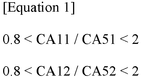
- a size of the effective aperture of each of the first lens and the fifth lens may satisfy Equation 1 below.
- CA11 means a size of an effective aperture on an object-side surface of the first lens
- CA12 means a size of an effective aperture on an image-side surface of the first lens
- CA51 means a size of an effective aperture on an object-side surface of the fifth lens
- CA52 means a size of an effective aperture on an image-side surface of the fifth lens.
- the size of the effective aperture of the first lens may be the largest among the sizes of the effective apertures of the first to fourth lenses.
- a distance in a direction of the optical axis from the image-side surface of the fifth lens to the image sensor is defined as a back focal length (BFL)
- BFL back focal length
- CA is a size of an effective aperture of the object-side surface or image-side surface of one lens selected from the first to fifth lenses.
- TTL total track length
- an effective focal length (EFL) of the optical system may be greater than 10 mm.
- the optical system may have a F-number smaller than 3.8.
- a chief ray incidence angle (CRA) of the optical system may be smaller than 40 degrees.
- the first lens may have positive refractive power.
- the fifth lens may have positive refractive power.
- An object-side surface of the third lens may have an inflection point.
- An optical system includes a light path changing member, a plurality of lenses, and an image sensor sequentially disposed along an optical axis from an object side to an image side, wherein the light path changing member includes a reflective mirror or a prism, when a distance between the plurality of lenses does not change and a distance in the optical axis direction from an image-side surface of the lens closest to the image sensor among the plurality of lenses to the image sensor is defined as BFL (Back focal length), the following Equation 4 may be satisfied.
- BFL Back focal length
- ImgH means a value of 1/2 of a diagonal length of the effective region of the image sensor.
- An optical system may have improved optical characteristics.
- the optical system may include the plurality of lenses, and an effective aperture of a last lens closest to the image sensor may be greater than an effective aperture of a first lens closest to the object side.
- the effective aperture of the last lens may be the largest among the plurality of lenses, and thus improved optical characteristics may be obtained when designing a zoom lens having image sensors of various sizes, such as small to large.
- the optical system according to the embodiment of the invention may minimize or prevent occurrence of phenomena such as flare and ghost.
- the optical system may have a relatively small BFL value. Accordingly, it is possible to minimize or prevent light incident on the optical system from being reflected on a structure between the last lens and the image sensor.
- the optical system may easily correct the CRA (Chief Ray Angle) value, so it may have improved optical characteristics.
- CRA Choef Ray Angle
- the description may include not only being directly connected, coupled or joined to the other component but also being “connected “, “coupled” or “joined” by another component between the component and the other component.
- the description includes not only when two components are in direct contact with each other, but also when one or more other components are formed or disposed between the two components.
- it may refer to a downward direction as well as an upward direction with respect to one element.
- the convex surface of the lens may mean that the lens surface of a region corresponding to the optical axis has a convex shape
- the concave surface of the lens may mean that the lens surface of a region corresponding to the optical axis has a concave shape
- the "object-side surface” may refer to a surface of the lens facing the object side with respect to the optical axis
- the "image-side surface” may refer to the surface of the lens facing the imaging surface with respect to the optical axis.
- the vertical direction may mean a direction perpendicular to the optical axis
- the end of the lens or lens surface may mean the most end of an effective region of the lens through which incident light passes.
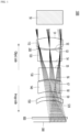
- FGI. 1 is a configuration diagram of an optical system according to an embodiment
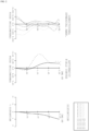
- FIG. 2 is a graph showing an aberration diagram of the optical system according to an embodiment.
- an optical system 1000 may include a plurality of lenses.
- the optical system 1000 may include four or more lenses.
- the optical system 1000 may include 5 or more lenses.
- the optical system 1000 may include a first lens 110, a second lens 120, a third lens 130, a fourth lens 140, and a fifth lens 150 sequentially arranged from the object side to the image side.
- the optical system 1000 may include a filter 500 and an image sensor 300 in an upward direction of the plurality of lenses 110, 120, 130, 140, and 150.
- the first to fifth lenses 110, 120, 130, 140, and 150 may be sequentially arranged along the optical axis of the optical system 1000. Light corresponding to image information of an object may pass through the first to fifth lenses 110, 120, 130, 140, and 150 sequentially and be incident on the image sensor 300.
- the optical system 1000 may further include an optical path changing member 50.
- the light path changing member 50 may change the path of light by reflecting light incident from the outside.
- the light path changing member 50 may include a reflective mirror or a prism.
- the light path changing member 50 may include a right-angle prism.
- the light path changing member 50 may change the path of light by reflecting the path of incident light at an angle of 90 degrees.
- the light path changing member 50 may be disposed closer to the object side than the first to fifth lenses 110, 120, 130, 140, and 150.
- the optical system 1000 includes the optical path changing member 50, a first lens 110, a second lens 120, a third lens 130, a fourth lens 140, a fifth lens 150, a filter 500 and an image sensor 300 sequentially disposed along the optical axis OA from the object side toward the image side.
- the light path changing member 50 may change the path of light in a set direction by reflecting light incident from the outside. That is, the light path changing member 50 may change the path of the light incident to the light path changing member 50 toward the first to fifth lenses 110, 120, 130, 140, and 150.
- Each of the first to fifth lenses 110, 120, 130, 140, and 150 may include an effective region and an ineffective region.
- the effective region may be a region through which light incident on the lens passes. That is, the effective region may be a region in which the incident light is refracted to implement optical characteristics.
- the non-effective region may be arranged around the effective region.
- the ineffective region may be a region in which the light is not incident. That is, the non-effective region may be a region unrelated to the optical characteristics. Also, the non-effective region may be a region fixed to a barrel (not shown) accommodating the lens.
- the optical system 1000 according to an embodiment of the invention may include an aperture stop 200 for adjusting the amount of incident light.
- the aperture stop 200 may be disposed between two lenses selected from among the first to fifth lenses 110, 120, 130, 140, and 150.
- the aperture stop 200 may be disposed between the first lens 110 and the second lens 120.
- At least one lens of the first to fifth lenses 110, 120, 130, 140, and 150 may serve as a aperture stop.
- one lens surface selected from among the first to fifth lenses 110, 120, 130, 140, and 150 may serve as an aperture stop to adjust the amount of light incident on the optical system 1000.
- the filter 500 may include at least one of an infrared filter and an optical filter such as a cover glass.
- the filter 500 may pass light of a set wavelength band and filter light of a different wavelength band.
- radiant heat emitted from external light may be blocked from being transferred to the image sensor 300.
- the filter 500 may transmit visible light and reflect infrared light.
- the image sensor 300 may detect light.
- the image sensor 300 may detect light sequentially passing through the first to fifth lenses 110, 120, 130, 140, and 150.
- the image sensor 300 may include a charge coupled device (CCD) or complementary metal oxide semiconductor (CMOS).
- CCD charge coupled device
- CMOS complementary metal oxide semiconductor
- the first lens 110 may have positive (+) refractive power.
- the first lens 110 may include a plastic or glass material.
- the first lens 110 may be made of a plastic material.
- the first lens 110 may include a first surface S1 defined as an obj ect-side surface and a second surface S2 defined as an image-side surface.
- the first surface S1 may be convex
- the second surface S2 may be convex. That is, the first lens 110 may have a convex shape on both sides.
- At least one of the first surface S1 and the second surface S2 may be an aspherical surface.
- both the first surface S1 and the second surface S2 may be aspherical.
- the second lens 120 may have negative (-) refractive power.
- the second lens 120 may include a plastic or glass material.
- the second lens 120 may be made of a plastic material.
- the second lens 120 may include a third surface S3 defined as an object-side surface and a fourth surface S4 defined as an image-side surface.
- the third surface S3 may be concave, and the fourth surface S4 may be convex. That is, the second lens 120 may have a meniscus shape convex to the image side.
- At least one of the third and fourth surfaces S3 and S4 may be an aspherical surface.
- both the third surface S3 and the fourth surface S4 may be aspheric surfaces.
- the third lens 130 may have negative (-) refractive power.
- the third lens 130 may include a plastic or glass material.
- the third lens 130 may be made of a plastic material.
- the third lens 130 may include a fifth surface S5 defined as an object-side surface and a sixth surface S6 defined as an image-side surface.
- the fifth surface S5 may be concave
- the sixth surface S6 may be concave. That is, the third lens 130 may have a concave shape on both sides.
- the third lens 130 may have an inflection point.
- an inflection point may be formed on the fifth surface S5 of the third lens 130.
- At least one of the fifth surface S5 and the sixth surface S6 may be an aspherical surface.
- both the fifth surface S5 and the sixth surface S6 may be aspheric surfaces.
- the fourth lens 140 may have positive (+) refractive power.
- the fourth lens 140 may include a plastic or glass material.
- the fourth lens 140 may be made of a plastic material.
- the fourth lens 140 may include a seventh surface S7 defined as an object-side surface and an eighth surface S8 defined as an image-side surface.
- the seventh surface S7 may be convex, and the eighth surface S8 may be concave. That is, the fourth lens 140 may have a meniscus shape convex toward the object side.
- At least one of the seventh surface S7 and the eighth surface S8 may be an aspheric surface.
- both the seventh surface S7 and the eighth surface S8 may be aspheric surfaces.
- the fifth lens 150 may have positive (+) refractive power.
- the fifth lens 150 may include a plastic or glass material.
- the fifth lens 150 may be made of a plastic material.
- the fifth lens 150 may include a ninth surface S9 defined as an object-side surface and a tenth surface S10 defined as an image-side surface.
- the ninth surface S9 may be convex, and the ninth surface S9 may be concave. That is, the fifth lens 150 may have a meniscus shape convex toward the object side.
- At least one of the ninth surface S9 and the tenth surface S10 may be an aspherical surface.
- both the ninth surface S9 and the tenth surface S10 may be aspheric surfaces.
- the first to fifth lenses 110, 120, 130, 140, and 150 may have a set effective aperture (e.g., clear aperture).
- a set effective aperture e.g., clear aperture
- each of the first to tenth surfaces S1, S2, S3, S4, S5, S6, S7, S8, S9, and S10 may have a set effective aperture.
- the fifth lens 150 closest to the image sensor 300 may have an effective aperture larger than the effective apertures of the first to fourth lenses 110, 120, 130, and 140.
- the effective apertures of the ninth surface S9 and the tenth surface S10 of the fifth lens 150 may be larger than the effective apertures of the first to eighth surfaces S1, S2, S3, S4, S5, S6, and S7, and S8.
- the first lens 110 may have the largest effective aperture among the first to fourth lenses 110, 120, 130, and 140.
- the effective apertures of the first surface S1 and the second surface S2 of the first lens 110 may be larger than the effective apertures of the third to eighth surfaces S3, S4, S5, S6, S7, and S8.
- the second lens 120 may have an effective aperture larger than the effective apertures of the third lens 130 and the fourth lens 140.
- the effective apertures of the third and fourth surfaces S3 and S4 of the second lens 120 may be larger than the effective apertures of the fifth to eighth surfaces S5, S6, S7, and S8 of the third and fourth lenses 130 and 140.
- the effective aperture of the fourth lens 140 may be larger than an effective aperture of the third lens 130.
- the effective apertures of the seventh and eighth surfaces S7 and S8 of the fourth lens 140 may be larger than the effective apertures of each of the fifth and sixth surfaces S5 and S6 of the third lens 130.
- the optical system 1000 according to an embodiment of the invention may satisfy at least one of equations described below. Accordingly, when the optical system 1000 according to the embodiment satisfies at least one of the following equations, it may have improved optical characteristics. 0.8 ⁇ CA 11 / CA 51 ⁇ 2 0.8 ⁇ CA 12 / CA 52 ⁇ 2
- CA11 means the size of the effective aperture of the object-side surface (first surface S1) of the first lens 110
- CA12 means the size of the effective aperture of the image-side surface (second surface S2) of the first lens 110
- CA51 means the size of the effective aperture of the object-side surface (ninth surface S9) of the fifth lens 150
- CA52 means the size of the effective aperture of the image-side surface (tenth surface S10) of the fifth lens 150.
- the effective aperture of the first lens 110 and the effective aperture of the fifth lens 150 may satisfy Equation 1-1 below. 0.8 ⁇ CA 11 / CA 51 ⁇ 1.8 0.8 ⁇ CA 12 / CA 52 ⁇ 1.8
- the effective aperture of the first lens 110 and the effective aperture of the fifth lens 150 may satisfy Equation 1-2 below.
- CA means the size of the effective aperture of the object-side surface or the image-side surface of any one lens selected from among the first to fifth lenses 110, 120, 130, 140, and 150.
- BFL Back focal length means the distance from the image-side surface (tenth surface S10) of the fifth lens 150 to the image sensor 300 in a direction of the optical axis.
- the effective aperture and BFL of the first to fifth lenses 110, 120, 130, 140, and 150 may satisfy Equation 2-1 below. 0.3 ⁇ CA / BFL ⁇ 1
- the effective aperture and BFL of the first to fifth lenses 110, 120, 130, 140, and 150 may satisfy Equation 2-2 below. 0.3 ⁇ CA / BFL ⁇ 0.8 3 ⁇ TTL / BFL ⁇ 5
- total track length (TTL) means the distance from the object-side surface (first surface S1) of the first lens 110 to the image sensor 300 in the optical axis direction.
- ImgH means a value of 1/2 of the length of the effective region of the image sensor 300 in the diagonal direction. That is, the ImgH means a distance in a vertical direction from the optical axis of the upper surface of the image sensor 300 to a region of 1 field.
- the ImgH and the BFL may satisfy Equation 4-1 below. 0.5 ⁇ ImgH / BFL ⁇ 1 EFL > 10 mm
- Equation 5 EFL means the effective focal length of the optical system 1000.
- F-number means a numerical value representing the brightness of the optical system.
- CRA Choef Ray Angle
- CT1 means the thickness of the center of the first lens 110
- CT5 means the thickness of the center of the fifth lens 150.
- f1 to f5 means focal lengths of the first to fifth lenses 110, 120, 130, 140, and 150, respectively.
- the absolute value of the focal length f5 of the fifth lens 150 may be greater than the sum of absolute values of the focal lengths f1, f2, f3, and f4 of the first to fourth lenses 110, 1201, 130, and 140. 20 ⁇ f 5 / EFL ⁇ 50
- f5 means the focal length of the fifth lens 150
- EFL means the effective focal length of the optical system 1000.
- Z cY 2 1 + 1 ⁇ 1 + K c 2 Y 2 + AY 4 + BY 6 + CY 8 + DY 10 + EY 12 + FY 14 + ⁇
- Z is Sag value, and may mean a distance in the optical axis direction from an arbitrary position on the aspherical surface to the apex of the aspheric surface.
- Y may mean a distance in a direction perpendicular to the optical axis from an arbitrary position on the aspherical surface to the optical axis.
- c may mean the curvature of the lens, and K may mean the conic constant.
- A, B, C, D, E, and F may mean aspheric constants.
- the optical system 1000 may satisfy at least one of Equations 1 to 9.
- the optical system 1000 may have improved optical characteristics.
- a characteristic deterioration phenomenon such as a flare or a ghost, which occurs when the light incident on the optical system 1000 is reflected by a mechanism accommodating the optical system 1000 from occurring.
- Table 1 shows data of lenses according to an embodiment of the invention.
- Lens Surface Radius of curvature Thickness/ Distance Effective aperture Refractive index
- Abbe number Lens 1 S1 4.043 1.5 1.55 1.5345 55.677 S2 -8.1302 0.1324 1.4863638
- Lens 2 S3 -7.3286 1.5 1.416846 1.6397 23.262 S4 -384.7888 0.8503 1.3826056
- Lens 3 S5 17.482107 1.5 1.3135073 1.5345 55.677 S6 3.8785 0.116989268 1.3031867
- Lens 4 S7 3.4444726 1.5 1.3192926 1.6397 23.262 S8 3.2521355 0.667342341 1.3771759 Lens 5 S9 6.2858121 0.5016011 1.5669996 1.5345 55.677 S10 6.2822957 1.5378562
- Table 2 shows the characteristics of an optical system and lenses according to an embodiment of the invention.
- Table 1 shows the radius of curvature of the first to fifth lenses 110, 120, 130, 140, and 150, the thickness (mm) of each lens, the distance (mm) between the lenses, the refractive index and Abbe number.
- the refractive indices of the first lens 110, the third lens 130, and the fifth lens 150 may be equal to each other, and the refractive indices of the second lens 120 and the fourth lens 140 may be equal to each other.
- the refractive indices of the first lens 110, the third lens 130, and the fifth lens 150 may be smaller than the refractive indices of the second lens 120 and the fourth lens 140.
- Abbe numbers of the first lens 110, the third lens 130, and the fifth lens 150 may be equal to each other, and the Abbe numbers of the second lens 120 and the fourth lens 140 may be equal to each other. At this time, the Abbe numbers of the first lens 110, the third lens 130, and the fifth lens 150 may be greater than the Abbe numbers of the second lens 120 and the fourth lens 140.
- Table 2 relates to the characteristics of the optical system 1000 according to the embodiment, and in Table 2, the total track length (TTL) is the distance (mm) on the optical axis from the apex of the object-side surface (first surface S1) of the first lens 110 to the upper surface of the image sensor 300, and EFL (effective focal length) means the focal length (mm) of the optical system 1000 including the first to fifth lenses 110, 120, 130, 140, and 150.
- TTL total track length
- EFL effective focal length
- BFL Back focal length
- each of f1 to f5 may mean a focal length (mm) of each of the first to fifth lenses 110, 120, 130, 140, and 150.
- the fifth lens 150 may have the largest focal length value among the first to fifth lenses 110, 120, 130, 140, and 150.
- Table 4 is the value of the optical system 1000 for the above equations. Referring to Table 4, it may be seen that the optical system 1000 according to the embodiment satisfies at least one of Equations 1 to 9. In detail, it may be seen that the optical system 1000 satisfies all of Equations 1 to 10. Accordingly, the optical system 1000 according to the embodiment may have aberration characteristics as shown in FIG. 2 .
- FIG. 2 is a graph showing an aberration diagram of an optical system 1000 according to an embodiment, in which spherical aberration, astigmatic field curves, and distortion are measured from left to right.
- X axis may represent a focal length (mm) and distortion (%)
- the Y axis may represent the height of an image sensor.
- a graph of spherical aberration is a graph of light in a wavelength band of 435 nm, 486 nm, 546 nm, 587 nm, and 656.3 nm
- a graph of astigmatism and distortion is a graph of light of a wavelength band of 546 nm.
- the optical system 1000 may have improved optical characteristics.
- the effective aperture of the fifth lens 150 closest to the image sensor 300 may be larger than the effective aperture of the first lens 110 closest to the object side, thereby improving optical characteristics.
- the effective aperture of the fifth lens 150 is the largest among the plurality of lenses, improved optical characteristics may be obtained when designing a zoom lens having image sensors 300 of various sizes, such as small to large.
- improved optical characteristics may be obtained when the optical system 1000 is applied as a telephoto lens.
- the optical system may have improved optical characteristics by having a relatively small Back focal length (BFL) value.
- BFL Back focal length
- the optical system 1000 according to the embodiment may have improved optical characteristics by easily correcting a CRA value, for example, an angle of light passing through the fifth lens 150 and incident on the image sensor 300.
Landscapes
- Physics & Mathematics (AREA)
- General Physics & Mathematics (AREA)
- Optics & Photonics (AREA)
- Lenses (AREA)
- Engineering & Computer Science (AREA)
- Multimedia (AREA)
- Signal Processing (AREA)
Abstract
Description
- Embodiments of the invention are directed to optics for improved optical performance.
- The camera module captures an object and stores it as an image or video, and is installed in various applications. In particular, the camera module is produced in a very small size and is applied to not only portable devices such as smartphones, tablet PCs, and laptops, but also drones and vehicles to provide various functions. For example, the optical system of the camera module may include an imaging lens for forming an image, and an image sensor for converting the formed image into an electrical signal. In this case, the camera module may perform an autofocus (AF) function of aligning the focal lengths of the lenses by automatically adjusting the distance between the image sensor and the imaging lens, and may perform a zooning function of zooming up or zooning out by increasing or decreasing the magnification of a remote object through a zoom lens. In addition, the camera module employs an image stabilization (IS) technology to correct or prevent image stabilization due to an unstable fixing device or a camera movement caused by a user's movement. The most important element for this camera module to obtain an image is an imaging lens that forms an image. Recently, interest in high efficiency such as high image quality and high resolution is increasing, and research on an optical system including plurality of lenses is being conducted in order to realize this. For example, research using a plurality of imaging lenses having positive (+) and/or negative (-) refractive power to implement a high-efficiency optical system is being conducted. However, when a plurality of lenses is included, there is a problem in that it is difficult to derive excellent optical properties and aberration properties.
- When the back focal length (BFL) of the optical system is increased, the light incident on the optical system is reflected on the inner surface of the instrument including the optical system, and may occurred as a phenomenon such as flare or ghost. Therefore, a new optical system capable of solving the above problems is required.
- Embodiments provide an optical system with improved optical properties.
- Embodiments provide an optical system with improved telescopic performance.
- An optical system according to an embodiment of an invention comprises a light path changing member and a plurality of lenses sequentially disposed along an optical axis from an object side to an image side, the light path changing member includes a reflective mirror or a prism, and a distance between the plurality of lenses does not change, and a lens closest to the image side among the plurality of lenses has an effective aperture larger than that of the other lenses.
- According to an embodiment of the invention, the plurality of lenses may include first to fifth lenses sequentially disposed along the optical axis in a direction from the object side to the image side. A size of the effective aperture of each of the first lens and the fifth lens may satisfy
Equation 1 below.
- (In
Equation 1, CA11 means a size of an effective aperture on an object-side surface of the first lens, and CA12 means a size of an effective aperture on an image-side surface of the first lens. In addition to, CA51 means a size of an effective aperture on an object-side surface of the fifth lens, and CA52 means a size of an effective aperture on an image-side surface of the fifth lens.) - According to an embodiment of the invention, the size of the effective aperture of the first lens may be the largest among the sizes of the effective apertures of the first to fourth lenses. When a distance in a direction of the optical axis from the image-side surface of the fifth lens to the image sensor is defined as a back focal length (BFL),
Equation 2 below may be satisfied.

- (In
Equation 2, CA is a size of an effective aperture of the object-side surface or image-side surface of one lens selected from the first to fifth lenses.) - According to an embodiment of the invention, when a distance in a direction of the optical axis from the object-side surface of the first lens to the image sensor is defined as a total track length (TTL), Equation 3 below may be satisfied.

- According to an embodiment of the invention, an effective focal length (EFL) of the optical system may be greater than 10 mm. The optical system may have a F-number smaller than 3.8. A chief ray incidence angle (CRA) of the optical system may be smaller than 40 degrees. The first lens may have positive refractive power. The fifth lens may have positive refractive power. An object-side surface of the third lens may have an inflection point.
- An optical system according to an embodiment of the invention includes a light path changing member, a plurality of lenses, and an image sensor sequentially disposed along an optical axis from an object side to an image side, wherein the light path changing member includes a reflective mirror or a prism, when a distance between the plurality of lenses does not change and a distance in the optical axis direction from an image-side surface of the lens closest to the image sensor among the plurality of lenses to the image sensor is defined as BFL (Back focal length), the following Equation 4 may be satisfied.

- (In Equation 4, ImgH means a value of 1/2 of a diagonal length of the effective region of the image sensor.)
- An optical system according to an embodiment of the invention may have improved optical characteristics. In detail, the optical system may include the plurality of lenses, and an effective aperture of a last lens closest to the image sensor may be greater than an effective aperture of a first lens closest to the object side. In particular, the effective aperture of the last lens may be the largest among the plurality of lenses, and thus improved optical characteristics may be obtained when designing a zoom lens having image sensors of various sizes, such as small to large.
- The optical system according to the embodiment of the invention may minimize or prevent occurrence of phenomena such as flare and ghost. In detail, the optical system may have a relatively small BFL value. Accordingly, it is possible to minimize or prevent light incident on the optical system from being reflected on a structure between the last lens and the image sensor. In addition, the optical system may easily correct the CRA (Chief Ray Angle) value, so it may have improved optical characteristics.
-
-
FIG. 1 is a configuration diagram of an optical system according to an embodiment. -
FIG. 2 is a graph showing an aberration diagram of an optical system according to an embodiment. - Hereinafter, preferred embodiments of the invention will be described in detail with reference to the accompanying drawings. However, a technical spirit of the invention is not limited to some embodiments to be described, and may be implemented in various other forms, and one or more of the components may be selectively combined and substituted for use within the scope of the technical spirit of the invention. In addition, the terms (including technical and scientific terms) used in the embodiments of the invention, unless specifically defined and described explicitly, may be interpreted in a meaning that may be generally understood by those having ordinary skill in the art to which the invention pertains, and terms that are commonly used such as terms defined in a dictionary should be able to interpret their meanings in consideration of the contextual meaning of the relevant technology.
- The terms used in the embodiments of the invention are for explaining the embodiments and are not intended to limit the invention. In this specification, the singular forms also may include plural forms unless otherwise specifically stated in a phrase, and in the case in which at least one (or one or more) of A and (and) B, C is stated, it may include one or more of all combinations that may be combined with A, B, and C. In describing the components of the embodiments of the invention, terms such as first, second, A, B, (a), and (b) may be used. Such terms are only for distinguishing the component from other component, and may not be determined by the term by the nature, sequence or procedure etc. of the corresponding constituent element. And when it is described that a component is "connected ", "coupled" or "joined" to another component, the description may include not only being directly connected, coupled or joined to the other component but also being "connected ", "coupled" or "joined" by another component between the component and the other component. In addition, in the case of being described as being formed or disposed "above (on)" or "below (under)" of each component, the description includes not only when two components are in direct contact with each other, but also when one or more other components are formed or disposed between the two components. In addition, when expressed as "above (on)" or "below (under)", it may refer to a downward direction as well as an upward direction with respect to one element.
- In the description of the invention, the convex surface of the lens may mean that the lens surface of a region corresponding to the optical axis has a convex shape, and the concave surface of the lens may mean that the lens surface of a region corresponding to the optical axis has a concave shape. In addition, the "object-side surface" may refer to a surface of the lens facing the object side with respect to the optical axis, and the "image-side surface" may refer to the surface of the lens facing the imaging surface with respect to the optical axis. In addition, the vertical direction may mean a direction perpendicular to the optical axis, and the end of the lens or lens surface may mean the most end of an effective region of the lens through which incident light passes.
- FGI. 1 is a configuration diagram of an optical system according to an embodiment, and
FIG. 2 is a graph showing an aberration diagram of the optical system according to an embodiment. - Referring to
FIG. 1 , anoptical system 1000 according to an embodiment of the invention may include a plurality of lenses. For example, theoptical system 1000 may include four or more lenses. In detail, theoptical system 1000 may include 5 or more lenses. - The
optical system 1000 may include afirst lens 110, asecond lens 120, athird lens 130, afourth lens 140, and afifth lens 150 sequentially arranged from the object side to the image side. Theoptical system 1000 may include afilter 500 and animage sensor 300 in an upward direction of the plurality oflenses fifth lenses optical system 1000. Light corresponding to image information of an object may pass through the first tofifth lenses image sensor 300. - The
optical system 1000 may further include an opticalpath changing member 50. The lightpath changing member 50 may change the path of light by reflecting light incident from the outside. The lightpath changing member 50 may include a reflective mirror or a prism. For example, the lightpath changing member 50 may include a right-angle prism. When the lightpath changing member 50 includes a right-angle prism, the lightpath changing member 50 may change the path of light by reflecting the path of incident light at an angle of 90 degrees. The lightpath changing member 50 may be disposed closer to the object side than the first tofifth lenses optical system 1000 includes the opticalpath changing member 50, afirst lens 110, asecond lens 120, athird lens 130, afourth lens 140, afifth lens 150, afilter 500 and animage sensor 300 sequentially disposed along the optical axis OA from the object side toward the image side. The lightpath changing member 50 may change the path of light in a set direction by reflecting light incident from the outside. That is, the lightpath changing member 50 may change the path of the light incident to the lightpath changing member 50 toward the first tofifth lenses - Each of the first to
fifth lenses optical system 1000 according to an embodiment of the invention may include anaperture stop 200 for adjusting the amount of incident light. Theaperture stop 200 may be disposed between two lenses selected from among the first tofifth lenses aperture stop 200 may be disposed between thefirst lens 110 and thesecond lens 120. At least one lens of the first tofifth lenses fifth lenses optical system 1000. - The
filter 500 may include at least one of an infrared filter and an optical filter such as a cover glass. Thefilter 500 may pass light of a set wavelength band and filter light of a different wavelength band. When thefilter 500 includes an infrared filter, radiant heat emitted from external light may be blocked from being transferred to theimage sensor 300. In addition, thefilter 500 may transmit visible light and reflect infrared light. - The
image sensor 300 may detect light. In detail, theimage sensor 300 may detect light sequentially passing through the first tofifth lenses image sensor 300 may include a charge coupled device (CCD) or complementary metal oxide semiconductor (CMOS). - Hereinafter, the plurality of lenses will be described in detail.
- The
first lens 110 may have positive (+) refractive power. Thefirst lens 110 may include a plastic or glass material. For example, thefirst lens 110 may be made of a plastic material. Thefirst lens 110 may include a first surface S1 defined as an obj ect-side surface and a second surface S2 defined as an image-side surface. The first surface S1 may be convex, and the second surface S2 may be convex. That is, thefirst lens 110 may have a convex shape on both sides. At least one of the first surface S1 and the second surface S2 may be an aspherical surface. For example, both the first surface S1 and the second surface S2 may be aspherical. - The
second lens 120 may have negative (-) refractive power. Thesecond lens 120 may include a plastic or glass material. For example, thesecond lens 120 may be made of a plastic material. Thesecond lens 120 may include a third surface S3 defined as an object-side surface and a fourth surface S4 defined as an image-side surface. The third surface S3 may be concave, and the fourth surface S4 may be convex. That is, thesecond lens 120 may have a meniscus shape convex to the image side. At least one of the third and fourth surfaces S3 and S4 may be an aspherical surface. For example, both the third surface S3 and the fourth surface S4 may be aspheric surfaces. - The
third lens 130 may have negative (-) refractive power. Thethird lens 130 may include a plastic or glass material. For example, thethird lens 130 may be made of a plastic material. Thethird lens 130 may include a fifth surface S5 defined as an object-side surface and a sixth surface S6 defined as an image-side surface. The fifth surface S5 may be concave, and the sixth surface S6 may be concave. That is, thethird lens 130 may have a concave shape on both sides. Also, thethird lens 130 may have an inflection point. In detail, an inflection point may be formed on the fifth surface S5 of thethird lens 130. At least one of the fifth surface S5 and the sixth surface S6 may be an aspherical surface. For example, both the fifth surface S5 and the sixth surface S6 may be aspheric surfaces. - The
fourth lens 140 may have positive (+) refractive power. Thefourth lens 140 may include a plastic or glass material. For example, thefourth lens 140 may be made of a plastic material. Thefourth lens 140 may include a seventh surface S7 defined as an object-side surface and an eighth surface S8 defined as an image-side surface. The seventh surface S7 may be convex, and the eighth surface S8 may be concave. That is, thefourth lens 140 may have a meniscus shape convex toward the object side. At least one of the seventh surface S7 and the eighth surface S8 may be an aspheric surface. For example, both the seventh surface S7 and the eighth surface S8 may be aspheric surfaces. - The
fifth lens 150 may have positive (+) refractive power. Thefifth lens 150 may include a plastic or glass material. For example, thefifth lens 150 may be made of a plastic material. Thefifth lens 150 may include a ninth surface S9 defined as an object-side surface and a tenth surface S10 defined as an image-side surface. The ninth surface S9 may be convex, and the ninth surface S9 may be concave. That is, thefifth lens 150 may have a meniscus shape convex toward the object side. At least one of the ninth surface S9 and the tenth surface S10 may be an aspherical surface. For example, both the ninth surface S9 and the tenth surface S10 may be aspheric surfaces. - The first to
fifth lenses - Among the first to
fifth lenses fifth lens 150 closest to theimage sensor 300 may have an effective aperture larger than the effective apertures of the first tofourth lenses fifth lens 150 may be larger than the effective apertures of the first to eighth surfaces S1, S2, S3, S4, S5, S6, and S7, and S8. Thefirst lens 110 may have the largest effective aperture among the first tofourth lenses first lens 110 may be larger than the effective apertures of the third to eighth surfaces S3, S4, S5, S6, S7, and S8. - The
second lens 120 may have an effective aperture larger than the effective apertures of thethird lens 130 and thefourth lens 140. For example, the effective apertures of the third and fourth surfaces S3 and S4 of thesecond lens 120 may be larger than the effective apertures of the fifth to eighth surfaces S5, S6, S7, and S8 of the third andfourth lenses fourth lens 140 may be larger than an effective aperture of thethird lens 130. For example, the effective apertures of the seventh and eighth surfaces S7 and S8 of thefourth lens 140 may be larger than the effective apertures of each of the fifth and sixth surfaces S5 and S6 of thethird lens 130. - The
optical system 1000 according to an embodiment of the invention may satisfy at least one of equations described below. Accordingly, when theoptical system 1000 according to the embodiment satisfies at least one of the following equations, it may have improved optical characteristics.

- In
Equation 1, CA11 means the size of the effective aperture of the object-side surface (first surface S1) of thefirst lens 110, and CA12 means the size of the effective aperture of the image-side surface (second surface S2) of thefirst lens 110. In addition, CA51 means the size of the effective aperture of the object-side surface (ninth surface S9) of thefifth lens 150, and CA52 means the size of the effective aperture of the image-side surface (tenth surface S10) of thefifth lens 150. - In detail, the effective aperture of the
first lens 110 and the effective aperture of thefifth lens 150 may satisfy Equation 1-1 below.

- In more detail, the effective aperture of the
first lens 110 and the effective aperture of thefifth lens 150 may satisfy Equation 1-2 below.


- In
Equation 2, CA means the size of the effective aperture of the object-side surface or the image-side surface of any one lens selected from among the first tofifth lenses fifth lens 150 to theimage sensor 300 in a direction of the optical axis. - In detail, the effective aperture and BFL of the first to
fifth lenses

- In more detail, the effective aperture and BFL of the first to
fifth lenses


- In Equation 3, total track length (TTL) means the distance from the object-side surface (first surface S1) of the
first lens 110 to theimage sensor 300 in the optical axis direction.

- In Equation 4, ImgH means a value of 1/2 of the length of the effective region of the
image sensor 300 in the diagonal direction. That is, the ImgH means a distance in a vertical direction from the optical axis of the upper surface of theimage sensor 300 to a region of 1 field. - In more detail, the ImgH and the BFL may satisfy Equation 4-1 below.


- In Equation 5, EFL means the effective focal length of the
optical system 1000.

- In Equation 6, F-number means a numerical value representing the brightness of the optical system.

- In Equation 7, CRA (Chief Ray Angle) means an incident angle of a chief ray incident on the
image sensor 300.
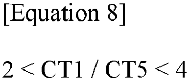
- In Equation 8, CT1 means the thickness of the center of the
first lens 110, and CT5 means the thickness of the center of thefifth lens 150.

- In Equation 9, f1 to f5 means focal lengths of the first to
fifth lenses fifth lens 150 may be greater than the sum of absolute values of the focal lengths f1, f2, f3, and f4 of the first tofourth lenses

- In
Equation 10, f5 means the focal length of thefifth lens 150, and EFL means the effective focal length of theoptical system 1000.

- In
Equation 10, Z is Sag value, and may mean a distance in the optical axis direction from an arbitrary position on the aspherical surface to the apex of the aspheric surface. Also, Y may mean a distance in a direction perpendicular to the optical axis from an arbitrary position on the aspherical surface to the optical axis. Also, c may mean the curvature of the lens, and K may mean the conic constant. Also, A, B, C, D, E, and F may mean aspheric constants. - The
optical system 1000 according to the embodiment may satisfy at least one ofEquations 1 to 9. In this case, theoptical system 1000 may have improved optical characteristics. In detail, when theoptical system 1000 satisfies at least one of the above-described equations, it is possible to prevent a characteristic deterioration phenomenon, such as a flare or a ghost, which occurs when the light incident on theoptical system 1000 is reflected by a mechanism accommodating theoptical system 1000 from occurring. - Table 1 shows data of lenses according to an embodiment of the invention.
[Table 1] Lens Surface Radius of curvature Thickness/ Distance Effective aperture Refractive index Abbe number Lens 1 S1 4.043 1.5 1.55 1.5345 55.677 S2 -8.1302 0.1324 1.4863638 Lens 2S3 -7.3286 1.5 1.416846 1.6397 23.262 S4 -384.7888 0.8503 1.3826056 Lens 3 S5 17.482107 1.5 1.3135073 1.5345 55.677 S6 3.8785 0.116989268 1.3031867 Lens 4 S7 3.4444726 1.5 1.3192926 1.6397 23.262 S8 3.2521355 0.667342341 1.3771759 Lens 5 S9 6.2858121 0.5016011 1.5669996 1.5345 55.677 S10 6.2822957 1.5378562 - Table 2 below shows the characteristics of an optical system and lenses according to an embodiment of the invention.
[Table 2] Item Embodiment TTL 11.08676 F-number 3.4647 EFL 10.7407 BFL 2.818 ImgH 2.051 f1 5.256428 f2 -11.58088 f3 -9.65706 f4 43.734218 f5 428.46201 - Table 1 shows the radius of curvature of the first to
fifth lenses first lens 110, thethird lens 130, and thefifth lens 150 may be equal to each other, and the refractive indices of thesecond lens 120 and thefourth lens 140 may be equal to each other. In this case, the refractive indices of thefirst lens 110, thethird lens 130, and thefifth lens 150 may be smaller than the refractive indices of thesecond lens 120 and thefourth lens 140. - Abbe numbers of the
first lens 110, thethird lens 130, and thefifth lens 150 may be equal to each other, and the Abbe numbers of thesecond lens 120 and thefourth lens 140 may be equal to each other. At this time, the Abbe numbers of thefirst lens 110, thethird lens 130, and thefifth lens 150 may be greater than the Abbe numbers of thesecond lens 120 and thefourth lens 140. - Table 2 relates to the characteristics of the
optical system 1000 according to the embodiment, and in Table 2, the total track length (TTL) is the distance (mm) on the optical axis from the apex of the object-side surface (first surface S1) of thefirst lens 110 to the upper surface of theimage sensor 300, and EFL (effective focal length) means the focal length (mm) of theoptical system 1000 including the first tofifth lenses fifth lens 150 to theimage sensor 300, each of f1 to f5 may mean a focal length (mm) of each of the first tofifth lenses fifth lens 150 may have the largest focal length value among the first tofifth lenses - In the
optical system 1000 according to the embodiment, the value of the aspherical surface coefficient of each lens is shown in Table 3.[Table 3] K A B C D E F G H J S1 - 4.624 774 - 0.226 312E-02 0.489 390E-02 - 0.509 701E-02 0.217 648E-02 - 0.566 567E-03 0.558 957E-04 0.000 000E+ 00 0.000 000E+ 00 0.000 00E+0 0 S2 0.000 000 - 0.419 606E-01 0.604 368E-01 - 0.470 338E-01 0.138 559E-01 0.375 169E-03 - 0.122 076E-02 0.278 259E-03 - 0.204 382E-04 0.000 000E+ 00 S3 - 7.463 160 - 0.232 627E-01 0.527 822E-01 - 0.444 088E-01 0.151 247E-01 - 0.146 984E-02 - 0.296 560E-03 0.625 074E-04 0.000 000E+ 00 0.000 00E+0 0 S4 -99.00 0000 0.119 356E-02 0.445 158E-0 -0.108 605E-01 0.641 443E-02 -0.599 468E-03 -0.179 139E-02 0.109 799E-02 -0.196 984E-03 0.000 000E+ 00 S5 - 99.00 0000 0.214 541E-02 - 0.365 989E-01 0.624 896E-01 -0. 62891 5E-01 0.298 347E-01 -0. 53109 8E-02 0.000 000E+ 00 0.000 000E+ 00 0.000 000E+ 00 S6 - 44.25 6666 0.637 372E-01 -0. 99568 4E-01 0.171 046E+ 00 -0. 90670 3E-01 -0. 16039 9E+00 0.293 791E+ 00 -0. 19873 3E+00 0.636 119E-01 -0. 80504 7E-02 S7 - 99.00 0000 0.114 492E+ 00 -0. 31889 0E+00 0.628 853E+ 00 -0. 78857 0E+00 0.602 565E+ 00 -0. 27060 9E+00 0.651 563E-01 -0. 64330 3E-02 0.000 000E+ 00 S8 0.684650 -0.230 664E-01 -0.204 520E-01 0.756 834E-01 -0.12092 6E+00 0.106326E+ 00 -0.524 879E-01 0.135195E-01 -0.13995 6E-02 0.000000E+ 00 S9 0.000 000 0.000 000E+ 00 0.000 000E+ 00 0.000 000E+ 00 0.000 000E+ 00 S10 
0.000 000 0.000 000E+ 00 0.000 000E+ 00 0.000 000E+ 00 0.000 000E+ 00 - Table 4 shows the values of
Equations 1 to 10 applied to the optical system according to the embodiment of the invention.[Table 4] Equation Embodiment Equation 1 0.8 < CA11 / CA51 < 2 CA11 / CA51 = 0.989 0.8 < CA12 / CA52 < 2 CA12 / CA52 = 0.966 Equation 20 < CA / BFL < 1 Satisfied with all first to fifth lenses Equation 3 3 < TTL / BFL < 5 TTL / BFL = 3.93 Equation 4 0.5 < ImgH / BFL < 1.5 ImgH / BFL = 0.727 Equation 5 EFL > 10mm Satisfaction Equation 6 F-number < 3.8 Satisfaction Equation 7 CRA < 40 < 40 Equation 8 2 < CT1 / CT5 < 4 CT1 / CT5 = 2.99 Equation 9 |f5| > |f1|+|f2|+|f3|+|f4| 428.462 > 80.969 Equation 1020 < f5 / EFL < 50 f5 / EFL = 39.891 - Table 4 is the value of the
optical system 1000 for the above equations. Referring to Table 4, it may be seen that theoptical system 1000 according to the embodiment satisfies at least one ofEquations 1 to 9. In detail, it may be seen that theoptical system 1000 satisfies all ofEquations 1 to 10. Accordingly, theoptical system 1000 according to the embodiment may have aberration characteristics as shown inFIG. 2 . In detail,FIG. 2 is a graph showing an aberration diagram of anoptical system 1000 according to an embodiment, in which spherical aberration, astigmatic field curves, and distortion are measured from left to right. InFIG. 2 , X axis may represent a focal length (mm) and distortion (%), and the Y axis may represent the height of an image sensor. Also, a graph of spherical aberration is a graph of light in a wavelength band of 435 nm, 486 nm, 546 nm, 587 nm, and 656.3 nm, and a graph of astigmatism and distortion is a graph of light of a wavelength band of 546 nm. Theoptical system 1000 according to an embodiment of the invention may have improved optical characteristics. In detail, in theoptical system 1000, the effective aperture of thefifth lens 150 closest to theimage sensor 300 may be larger than the effective aperture of thefirst lens 110 closest to the object side, thereby improving optical characteristics. In particular, since the effective aperture of thefifth lens 150 is the largest among the plurality of lenses, improved optical characteristics may be obtained when designing a zoom lens havingimage sensors 300 of various sizes, such as small to large. In addition, when theoptical system 1000 is applied as a telephoto lens, improved optical characteristics may be obtained. - The optical system may have improved optical characteristics by having a relatively small Back focal length (BFL) value. In detail, as the distance BFL between the
image sensor 300 and thefifth lens 150 has a relatively small value, light incident to theoptical system 1000 may be prevented or minimized from being reflected on a structure between thefifth lens 150 and theimage sensor 300. Accordingly, theoptical system 1000 according to the embodiment may have improved optical characteristics by easily correcting a CRA value, for example, an angle of light passing through thefifth lens 150 and incident on theimage sensor 300. - Features, structures, effects, etc. described in the above embodiments are included in at least one embodiment of the invention, and are not necessarily limited to only one embodiment. Furthermore, features, structures, effects, etc. illustrated in each embodiment may be combined or modified for other embodiments by those of ordinary skill in the art to which the embodiments belong. Accordingly, the contents related to such combinations and modifications should be interpreted as being included in the scope of the invention. In addition, although the embodiment has been described above, it is only an example and does not limit the invention, and those of ordinary skill in the art to which the invention pertains are exemplified above in a range that does not depart from the essential characteristics of the present embodiment. It may be seen that various modifications and applications that have not been made are possible. For example, each component specifically shown in the embodiment may be implemented by modification. And the differences related to these modifications and applications should be construed as being included in the scope of the invention defined in the appended claims.
Claims (13)
- An optical system comprising:an optical path changing member and a plurality of lenses sequentially disposed along an optical axis from an object side to an image side,wherein the light path changing member includes a reflective mirror or a prism,wherein a distance between the plurality of lenses does not change,wherein a lens closest to an image side of the plurality of lenses has a larger effective aperture than the other lenses.
- The optical system of claim 1,
wherein the plurality of lenses includes:
first to fifth lenses sequentially disposed along the optical axis from the object side to the image side. - The optical system of claim 2,
wherein a size of an effective aperture of each of the first lens and the fifth lens satisfies Equation 1 below:
- The optical system of claim 3,
wherein the size of the effective aperture of the first lens is the largest among sizes of effective apertures of the first to fourth lenses. - The optical system of claim 3,
wherein when a distance in a direction of the optical axis from the image-side surface of the fifth lens to the image sensor is defined as BFL (Back focal length), the following Equaltion 2 satisfies:
- The optical system of claim 5,
wherein when a distance in a direction of the optical axis from the object-side surface of the first lens to an image sensor is defined as a total track length (TTL), the following Equation 3 satisfies:
- The optical system of claim 2,
wherein an effective focal length (EFL) of the optical system is greater than 10 mm. - The optical system of claim 2,
wherein the optical system has F-number smaller than 3.8. - The optical system of claim 2,
wherein the optical system has a chief ray incidence angle (CRA) of less than 40. - The optical system of claim 2,
wherein the first lens has a positive refractive power. - The optical system of claim 2,
wherein the fifth lens has a positive refractive power. - The optical system of claim 2,
wherein an object-side surface of the third lens has an inflection point. - An optical system comprising:an optical path changing member and a plurality of lenses sequentially disposed along an optical axis from an object side to an image side; andan image sensor,wherein the light path changing member includes a reflective mirror or a prism,wherein a distance between the plurality of lenses does not change,wherein when a distance in a direction of the optical axis from an image-side surface of a lens closest to the image sensor of the plurality of lenses to the image sensor is defined as BFL (Back focus length), the following Equation 4 satisfies:

Applications Claiming Priority (2)
| Application Number | Priority Date | Filing Date | Title |
|---|---|---|---|
| KR1020200097261A KR20220017139A (en) | 2020-08-04 | 2020-08-04 | Optical system |
| PCT/KR2021/010246 WO2022031017A1 (en) | 2020-08-04 | 2021-08-04 | Optical system |
Publications (2)
| Publication Number | Publication Date |
|---|---|
| EP4194919A1 true EP4194919A1 (en) | 2023-06-14 |
| EP4194919A4 EP4194919A4 (en) | 2024-01-17 |
Family
ID=80117552
Family Applications (1)
| Application Number | Title | Priority Date | Filing Date |
|---|---|---|---|
| EP21852456.9A Pending EP4194919A4 (en) | 2020-08-04 | 2021-08-04 | OPTICAL SYSTEM |
Country Status (6)
| Country | Link |
|---|---|
| US (1) | US12607829B2 (en) |
| EP (1) | EP4194919A4 (en) |
| JP (1) | JP7826283B2 (en) |
| KR (1) | KR20220017139A (en) |
| CN (1) | CN116097146B (en) |
| WO (1) | WO2022031017A1 (en) |
Families Citing this family (2)
| Publication number | Priority date | Publication date | Assignee | Title |
|---|---|---|---|---|
| DE102022131290A1 (en) * | 2021-11-26 | 2023-06-01 | Huizhou Star Poly Yu Intelligent Technology Co., Ltd. | IMAGE ARRANGEMENT, ILLUMINATION PROJECTION DEVICE AND WELCOME LAMP |
| CN119355925B (en) * | 2024-12-23 | 2025-05-09 | 宁波舜宇车载光学技术有限公司 | Optical lenses and electronic devices |
Family Cites Families (19)
| Publication number | Priority date | Publication date | Assignee | Title |
|---|---|---|---|---|
| JPS60260014A (en) | 1984-06-07 | 1985-12-23 | Konishiroku Photo Ind Co Ltd | Wide angle lens |
| JP3573474B2 (en) | 1993-11-30 | 2004-10-06 | オリンパス株式会社 | Visual display device |
| JP4416767B2 (en) | 1998-10-02 | 2010-02-17 | キヤノン株式会社 | Imaging lens and image reading apparatus using the same |
| JP2007034103A (en) | 2005-07-29 | 2007-02-08 | Eastman Kodak Co | Wide angle lens and camera |
| JP2010260014A (en) | 2009-05-08 | 2010-11-18 | Nippon Bee Chemical Co Ltd | Method for forming coating film on carbon fiber reinforced plastic |
| JP6341442B2 (en) * | 2014-01-28 | 2018-06-20 | 株式会社リコー | Image reading lens, image reading apparatus, and image forming apparatus |
| TWI616675B (en) | 2016-07-14 | 2018-03-01 | 大立光電股份有限公司 | Optical camera system group, image capturing device and electronic device |
| TWI607238B (en) | 2016-08-22 | 2017-12-01 | 大立光電股份有限公司 | Optical camera system group, image capturing device and electronic device |
| KR102815108B1 (en) | 2016-09-21 | 2025-06-04 | 삼성전자주식회사 | Optical lens assembly and electronic apparatus having the same |
| KR101901701B1 (en) | 2016-12-28 | 2018-09-27 | 삼성전기 주식회사 | Optical system |
| KR101963591B1 (en) * | 2016-12-29 | 2019-04-01 | 삼성전기주식회사 | Optical system and portable electronic device including the same |
| TWI613481B (en) | 2017-02-08 | 2018-02-01 | 大立光電股份有限公司 | Photographing optical lens assembly, image capturing unit and electronic device |
| CN113031219A (en) * | 2017-07-23 | 2021-06-25 | 核心光电有限公司 | Folding lens kit |
| KR101956705B1 (en) | 2017-08-21 | 2019-03-11 | 삼성전기주식회사 | Optical system |
| TWI637207B (en) * | 2017-09-22 | 2018-10-01 | 大立光電股份有限公司 | Imaging lens group, image capturing device and electronic device |
| CN109358410B (en) * | 2018-12-14 | 2024-02-23 | 浙江舜宇光学有限公司 | Optical imaging lens group |
| CN111352212A (en) | 2018-12-23 | 2020-06-30 | 辽宁中蓝电子科技有限公司 | Large-view-field angle long-focus periscope lens |
| JP7185187B2 (en) | 2019-08-13 | 2022-12-07 | コニカミノルタ株式会社 | Imaging optical system and imaging device |
| CN111308672B (en) | 2020-04-10 | 2025-06-17 | 浙江舜宇光学有限公司 | Optical imaging system |
-
2020
- 2020-08-04 KR KR1020200097261A patent/KR20220017139A/en active Pending
-
2021
- 2021-08-04 JP JP2023506563A patent/JP7826283B2/en active Active
- 2021-08-04 WO PCT/KR2021/010246 patent/WO2022031017A1/en not_active Ceased
- 2021-08-04 EP EP21852456.9A patent/EP4194919A4/en active Pending
- 2021-08-04 US US18/019,596 patent/US12607829B2/en active Active
- 2021-08-04 CN CN202180054539.3A patent/CN116097146B/en active Active
Also Published As
| Publication number | Publication date |
|---|---|
| JP7826283B2 (en) | 2026-03-09 |
| KR20220017139A (en) | 2022-02-11 |
| EP4194919A4 (en) | 2024-01-17 |
| CN116097146B (en) | 2026-04-21 |
| JP2023536294A (en) | 2023-08-24 |
| CN116097146A (en) | 2023-05-09 |
| WO2022031017A1 (en) | 2022-02-10 |
| US12607829B2 (en) | 2026-04-21 |
| US20230280568A1 (en) | 2023-09-07 |
Similar Documents
| Publication | Publication Date | Title |
|---|---|---|
| US12124013B2 (en) | Optical imaging system | |
| US12092796B2 (en) | Optical imaging lens assembly | |
| US12487433B2 (en) | Optical system comprising first to seventh lenses sequentially arranged along an optical axis and camera module comprising the same | |
| US20190170987A1 (en) | Camera lens assembly | |
| EP4194920B1 (en) | Optical system | |
| KR101729470B1 (en) | Photographic Lens Optical System | |
| KR102302118B1 (en) | Optical imaging system | |
| EP4198600A1 (en) | Optical system | |
| EP4194919A1 (en) | Optical system | |
| KR20220169216A (en) | Optical system and camera module inclduing the same | |
| KR20160059239A (en) | Photographic Lens Optical System | |
| EP4261586A1 (en) | Optical system and camera module comprising same | |
| CN211905838U (en) | Optical imaging system | |
| EP4261589A1 (en) | Optical system and camera module including same | |
| US20240094509A1 (en) | Optical system | |
| KR20220032891A (en) | Optical system | |
| KR102491911B1 (en) | High definition lens system | |
| KR102139492B1 (en) | Lens optical system | |
| KR20230158177A (en) | Optical system and camera module including the same | |
| KR20220148028A (en) | Optical system | |
| KR20230037401A (en) | Optical system and camera module including the same | |
| KR20220032900A (en) | Optical system | |
| KR20220009668A (en) | Optical system |
Legal Events
| Date | Code | Title | Description |
|---|---|---|---|
| STAA | Information on the status of an ep patent application or granted ep patent |
Free format text: STATUS: THE INTERNATIONAL PUBLICATION HAS BEEN MADE |
|
| PUAI | Public reference made under article 153(3) epc to a published international application that has entered the european phase |
Free format text: ORIGINAL CODE: 0009012 |
|
| STAA | Information on the status of an ep patent application or granted ep patent |
Free format text: STATUS: REQUEST FOR EXAMINATION WAS MADE |
|
| 17P | Request for examination filed |
Effective date: 20230227 |
|
| AK | Designated contracting states |
Kind code of ref document: A1 Designated state(s): AL AT BE BG CH CY CZ DE DK EE ES FI FR GB GR HR HU IE IS IT LI LT LU LV MC MK MT NL NO PL PT RO RS SE SI SK SM TR |
|
| DAV | Request for validation of the european patent (deleted) | ||
| DAX | Request for extension of the european patent (deleted) | ||
| A4 | Supplementary search report drawn up and despatched |
Effective date: 20231220 |
|
| RIC1 | Information provided on ipc code assigned before grant |
Ipc: G02B 9/60 20060101ALI20231214BHEP Ipc: G02B 13/00 20060101AFI20231214BHEP |
|
| STAA | Information on the status of an ep patent application or granted ep patent |
Free format text: STATUS: EXAMINATION IS IN PROGRESS |
|
| 17Q | First examination report despatched |
Effective date: 20251105 |