EP4194885A1 - Method for determining the mobility status of a target object - Google Patents
Method for determining the mobility status of a target object Download PDFInfo
- Publication number
- EP4194885A1 EP4194885A1 EP21213425.8A EP21213425A EP4194885A1 EP 4194885 A1 EP4194885 A1 EP 4194885A1 EP 21213425 A EP21213425 A EP 21213425A EP 4194885 A1 EP4194885 A1 EP 4194885A1
- Authority
- EP
- European Patent Office
- Prior art keywords
- sensor
- beam vector
- stationary
- radar
- target object
- Prior art date
- Legal status (The legal status is an assumption and is not a legal conclusion. Google has not performed a legal analysis and makes no representation as to the accuracy of the status listed.)
- Granted
Links
Images



Classifications
-
- G—PHYSICS
- G01—MEASURING; TESTING
- G01S—RADIO DIRECTION-FINDING; RADIO NAVIGATION; DETERMINING DISTANCE OR VELOCITY BY USE OF RADIO WAVES; LOCATING OR PRESENCE-DETECTING BY USE OF THE REFLECTION OR RERADIATION OF RADIO WAVES; ANALOGOUS ARRANGEMENTS USING OTHER WAVES
- G01S7/00—Details of systems according to groups G01S13/00, G01S15/00, G01S17/00
- G01S7/02—Details of systems according to groups G01S13/00, G01S15/00, G01S17/00 of systems according to group G01S13/00
- G01S7/41—Details of systems according to groups G01S13/00, G01S15/00, G01S17/00 of systems according to group G01S13/00 using analysis of echo signal for target characterisation; Target signature; Target cross-section
-
- G—PHYSICS
- G01—MEASURING; TESTING
- G01S—RADIO DIRECTION-FINDING; RADIO NAVIGATION; DETERMINING DISTANCE OR VELOCITY BY USE OF RADIO WAVES; LOCATING OR PRESENCE-DETECTING BY USE OF THE REFLECTION OR RERADIATION OF RADIO WAVES; ANALOGOUS ARRANGEMENTS USING OTHER WAVES
- G01S13/00—Systems using the reflection or reradiation of radio waves, e.g. radar systems; Analogous systems using reflection or reradiation of waves whose nature or wavelength is irrelevant or unspecified
- G01S13/02—Systems using reflection of radio waves, e.g. primary radar systems; Analogous systems
- G01S13/06—Systems determining position data of a target
- G01S13/42—Simultaneous measurement of distance and other co-ordinates
-
- G—PHYSICS
- G01—MEASURING; TESTING
- G01S—RADIO DIRECTION-FINDING; RADIO NAVIGATION; DETERMINING DISTANCE OR VELOCITY BY USE OF RADIO WAVES; LOCATING OR PRESENCE-DETECTING BY USE OF THE REFLECTION OR RERADIATION OF RADIO WAVES; ANALOGOUS ARRANGEMENTS USING OTHER WAVES
- G01S13/00—Systems using the reflection or reradiation of radio waves, e.g. radar systems; Analogous systems using reflection or reradiation of waves whose nature or wavelength is irrelevant or unspecified
- G01S13/88—Radar or analogous systems specially adapted for specific applications
- G01S13/93—Radar or analogous systems specially adapted for specific applications for anti-collision purposes
- G01S13/931—Radar or analogous systems specially adapted for specific applications for anti-collision purposes of land vehicles
-
- G—PHYSICS
- G01—MEASURING; TESTING
- G01S—RADIO DIRECTION-FINDING; RADIO NAVIGATION; DETERMINING DISTANCE OR VELOCITY BY USE OF RADIO WAVES; LOCATING OR PRESENCE-DETECTING BY USE OF THE REFLECTION OR RERADIATION OF RADIO WAVES; ANALOGOUS ARRANGEMENTS USING OTHER WAVES
- G01S13/00—Systems using the reflection or reradiation of radio waves, e.g. radar systems; Analogous systems using reflection or reradiation of waves whose nature or wavelength is irrelevant or unspecified
- G01S13/02—Systems using reflection of radio waves, e.g. primary radar systems; Analogous systems
- G01S13/50—Systems of measurement based on relative movement of target
- G01S13/52—Discriminating between fixed and moving objects or between objects moving at different speeds
-
- G—PHYSICS
- G01—MEASURING; TESTING
- G01S—RADIO DIRECTION-FINDING; RADIO NAVIGATION; DETERMINING DISTANCE OR VELOCITY BY USE OF RADIO WAVES; LOCATING OR PRESENCE-DETECTING BY USE OF THE REFLECTION OR RERADIATION OF RADIO WAVES; ANALOGOUS ARRANGEMENTS USING OTHER WAVES
- G01S13/00—Systems using the reflection or reradiation of radio waves, e.g. radar systems; Analogous systems using reflection or reradiation of waves whose nature or wavelength is irrelevant or unspecified
- G01S13/02—Systems using reflection of radio waves, e.g. primary radar systems; Analogous systems
- G01S13/50—Systems of measurement based on relative movement of target
- G01S13/52—Discriminating between fixed and moving objects or between objects moving at different speeds
- G01S13/522—Discriminating between fixed and moving objects or between objects moving at different speeds using transmissions of interrupted pulse modulated waves
- G01S13/524—Discriminating between fixed and moving objects or between objects moving at different speeds using transmissions of interrupted pulse modulated waves based upon the phase or frequency shift resulting from movement of objects, with reference to the transmitted signals, e.g. coherent MTi
-
- G—PHYSICS
- G01—MEASURING; TESTING
- G01S—RADIO DIRECTION-FINDING; RADIO NAVIGATION; DETERMINING DISTANCE OR VELOCITY BY USE OF RADIO WAVES; LOCATING OR PRESENCE-DETECTING BY USE OF THE REFLECTION OR RERADIATION OF RADIO WAVES; ANALOGOUS ARRANGEMENTS USING OTHER WAVES
- G01S7/00—Details of systems according to groups G01S13/00, G01S15/00, G01S17/00
- G01S7/02—Details of systems according to groups G01S13/00, G01S15/00, G01S17/00 of systems according to group G01S13/00
- G01S7/41—Details of systems according to groups G01S13/00, G01S15/00, G01S17/00 of systems according to group G01S13/00 using analysis of echo signal for target characterisation; Target signature; Target cross-section
- G01S7/415—Identification of targets based on measurements of movement associated with the target
-
- G—PHYSICS
- G01—MEASURING; TESTING
- G01S—RADIO DIRECTION-FINDING; RADIO NAVIGATION; DETERMINING DISTANCE OR VELOCITY BY USE OF RADIO WAVES; LOCATING OR PRESENCE-DETECTING BY USE OF THE REFLECTION OR RERADIATION OF RADIO WAVES; ANALOGOUS ARRANGEMENTS USING OTHER WAVES
- G01S13/00—Systems using the reflection or reradiation of radio waves, e.g. radar systems; Analogous systems using reflection or reradiation of waves whose nature or wavelength is irrelevant or unspecified
- G01S13/88—Radar or analogous systems specially adapted for specific applications
- G01S13/93—Radar or analogous systems specially adapted for specific applications for anti-collision purposes
- G01S13/931—Radar or analogous systems specially adapted for specific applications for anti-collision purposes of land vehicles
- G01S2013/9327—Sensor installation details
Definitions
- the present disclosure relates to methods and systems for determining the mobility status of a target object, i.e. for determining whether a target object is stationary or moving.
- AFRR range rate
- Detections from moving and stationary targets are usually distinguished by comparing a measured range rate with an expected range rate from a stationary target. If the deviation between the actual and expected range rates is smaller than a predetermined threshold, the radar detection is regarded as originating from a stationary target.
- estimating the expected range rate requires determining the azimuth angle of the target object under consideration. Therefore, performing a "full classical" angle finding method may be required to carry out such a stationary versus moving check for the target object.
- the full classical angle finding methods may rely on Fourier transform techniques or on an iterative adaptive approach (IAA), amongst others.
- radar angle finding usually needs some kind of ground truth measurement of the angle which may be performed in an anechoic chamber.
- measurements in such an anechoic chamber are usually cumbersome.
- the characteristics of the radar system may be affected if the radar system is mounted in a vehicle after the calibration in the anechoic chamber.
- the present disclosure provides a computer implemented method, a computer system and a non-transitory computer readable medium according to the independent claims. Exemplary embodiments are given in the subclaims, the description and the drawings.
- the present disclosure is directed at a computer implemented method for determining a mobility status of a target object located in an environment of a sensor configured to monitor a surrounding environment of a vehicle.
- the method comprises the following steps performed by computer hardware components: determining a detection angle of the target object with respect to the sensor based on data acquired by the sensor; predicting an ideal beam vector for a stationary object based on the detection angle; normalizing the ideal beam vector and a measured beam vector which is obtained from the data acquired by the sensor; determining a correlation of the normalized ideal beam vector and the normalized measured beam vector; and determining, based on the correlation of the normalized ideal and measured beam vectors, a score indicating whether the target object is stationary or moving.
- the sensor may be a radar sensor, and the detection angle may be the azimuth angle with respect to a boresight direction of the sensor. Further, the target object may be located in an external environment of a host vehicle in which the sensor is installed, and the sensor may therefore be configured to monitor the environment of the host vehicle.
- the detection angle may be determined e.g. based on a range rate or "Doppler" which is given as the negative value of the range rate provided by sensor detections, e.g. radar detections.
- sensor detections e.g. radar detections.
- the ideal beam vector is predicted and correlated with the beam vector based on the data acquired by the sensor, wherein such a measured beam vector may be provided e.g. by a Fourier transform of the sensor detections as is known in the field of radar technology. Based on this correlation of the beam vectors, the score is determined as a measure for the target object to be stationary.
- a score being greater than a first threshold may indicate that the target object is stationary
- a score which is lower than a second threshold being equal to or smaller than the first threshold e.g. close to 1
- a stationary target object may be assumed if the score exceeds a predefined value.
- the method requires a low computational effort since the stationary/moving test mostly relies on the correlation of the ideal and measured beam vectors determined for the target object.
- the result of the method i.e. the information whether the target object is stationary or moving, may be used by further applications which are installed e.g. in a vehicle. Such applications may include angle finding from range rate (AFFR).
- AFFR angle finding from range rate
- the senor may include a radar sensor, and the sensor data may include a range rate determined based on radar detections of the radar sensor.
- the detection angle of the target object may therefore be determined in a direct and efficient way.
- the detection angle of the target object may be determined by solving an algebraic equation, leading to a further reduction of the computational effort of the method.
- An ambiguity may be determined for the solution of the algebraic equation. If such an ambiguity is determined, a correlation of a beam vector derived from sensor data and of a reference vector may be used in order to resolve the ambiguity. By resolving the ambiguity, the reliability of the method may be further improved.
- the reference vector may include data based from a reflection point originating from a predetermined axis, e.g. at boresight with respect to the sensor.
- the sensor may include a radar sensor comprising a plurality of equally spaced antenna elements.
- the ideal beam vector may depend on a ratio of the constant distance between the antenna elements and a wavelength of radar waves transmitted by the radar sensor. Moreover, a product of the ratio and the sine of the detection angle may define a phase relationship between components of the ideal beam vector. Therefore, predicting the ideal beam vector may be performed in an efficient manner with low computational effort.
- Calculating the correlation of the normalized ideal and measured beam vectors may include calculating a cosine coefficient based on the normalized ideal beam vector and the normalized measured beam vector.
- a calibration matrix of the sensor may be applied to the measured beam vector.
- the measured beam vector may be multiplied by the calibration matrix and normalized thereafter, and an inner product of the result and the ideal beam vector may be calculated in order to provide the cosine coefficient.
- the calibration matrix may be determined based on an initial diagonal calibration matrix which may be determined empirically, e.g. in an anechoic chamber at an azimuth angle of zero degree.
- the calibration matrix may be initialized via statistical methods. In both cases, the calibration matrix may be available for the method, e.g. by obtaining the calibration matrix from a database where the calibration matrix is stored after performing one of the calibration procedures.
- the absolute value of the cosine coefficient may directly provide the score for the target object being stationary.
- the score may be equal to the absolute value of the cosine coefficient.
- the target object may be determined to be stationary if the score or the absolute value of the cosine coefficient is greater than a predetermined threshold.
- the threshold may include a value of approximately 0.9 such that the threshold may be in a range e.g. from 0.88 to 0.92.
- two classes of target objects may be defined, i.e. one class for stationary objects and one class for moving objects or outliers. Hence, it may be decided in an efficient manner based on the absolute value of the cosine coefficient and the threshold whether the target object is stationary or moving.
- the ego-motion of the vehicle may be determined based on the target objects which are determined to be stationary, while moving target objects or outliers are not considered.
- the at least one dynamic parameter may include a linear velocity and/or an angular velocity of the vehicle.
- the present disclosure is directed at a computer system, said computer system comprising a plurality of computer hardware components configured to carry out several or all steps of the computer implemented method described herein. Therefore, the benefits, the advantages and the disclosure as described above for the method are also valid for the computer system.
- the computer system may comprise a plurality of computer hardware components, for example a processor, a processing unit or a processing network, at least one memory, for example a memory unit or a memory network, and at least one non-transitory data storage. It will be understood that further computer hardware components may be provided and used for carrying out steps of the computer implemented method in the computer system.
- the non-transitory data storage and/or the memory unit may comprise a computer program for instructing the computer to perform several or all steps or aspects of the computer implemented method described herein, for example using the processing unit and the at least one memory unit.
- the computer system further comprises: a radar sensor configured to acquire radar detections; wherein the computer system is configured to determine a range rate based on the radar detections; and wherein the computer system is configured to determine a measured beam vector based on the radar detections.
- the radar sensor comprises a plurality of antenna elements, for example arranged as an antenna array.
- the present disclosure is directed at a vehicle comprising the computer system as described herein; and a radar sensor.
- processing device and processing unit may refer to, be part of, or include an Application Specific Integrated Circuit (ASIC); an electronic circuit; a combinational logic circuit; a field programmable gate array (FPGA); a processor (shared, dedicated, or group) that executes code; other suitable components that provide the described functionality; or a combination of some or all of the above, such as in a system-on-chip.
- ASIC Application Specific Integrated Circuit
- FPGA field programmable gate array
- processor shared, dedicated, or group
- the processing device and the processing unit may include memory (shared, dedicated, or group) that stores code executed by the processor.
- the present disclosure is directed at a non-transitory computer readable medium comprising instructions for carrying out several or all steps or aspects of the computer implemented method described herein.
- the computer readable medium may be configured as: an optical medium, such as a compact disc (CD) or a digital versatile disk (DVD); a magnetic medium, such as a hard disk drive (HDD); a solid state drive (SSD); a read only memory (ROM); a flash memory; or the like.
- the computer readable medium may be configured as a data storage that is accessible via a data connection, such as an internet connection.
- the computer readable medium may, for example, be an online data repository or a cloud storage.
- the present disclosure is also directed at a computer program for instructing a computer to perform several or all steps or aspects of the computer implemented method described herein.
- Fig. 1 depicts a vehicle 10 including a computer system 11 for carrying out a method for determining a mobility status of a target object, i.e. for determining whether a target object is stationary or moving.
- the computer system 11 includes a radar sensor 13 and a processing unit 15 which is connected to the radar sensor 13 and configured to receive data acquired by the radar sensor 13 and to analyze these data according to the steps of the method.
- a sensor-based coordinate system 17 which includes an x-axis 19 and a y-axis 21, wherein the x-axis 19 coincides with the longitudinal axis of the vehicle 10, whereas the y-axis 21 coincides with the lateral axis with respect to the vehicle 10.
- the radar sensor 13 is configured to transmit radar waves and to provide radar detections r det which originate from radar waves being reflected by target objects 23, 25.
- the target objects 23, 25 include two different classes of objects, i.e. a class for moving objects 23, like other vehicles, and a class for stationary objects 25, like buildings etc.
- determining a detection or azimuth angle from range rate requires stationary target objects 25.
- the detection is considered as stationary, i.e. originating from a stationary target object 25.
- a predefined threshold T i.e.
- the present disclosure provides a method for determining whether a target object is stationary or moving, wherein the method includes five basic steps described below.
- the method requires a measured beam vector b and a related Doppler d (or range rate) which are based on radar detections provided by the radar sensor 13 (see Fig. 1 ).
- information about the motion of the host vehicle 10 is required, i.e. its velocity and its yaw rate.
- a first step includes calculating a detection or azimuth angle ⁇ D from the Doppler d using the motion of the host vehicle.
- ⁇ D Since a quadratic equation is solved in order to determine ⁇ D , there are usually two ambiguous solutions. This ambiguity can be resolved by considering a correlation between the measured beam vector b and a reference vector which includes data based from a reflection point originating from a predetermined axis, e.g. at boresight with respect to the radar sensor 13. After resolving the ambiguity of the solutions of the quadratic equation, the final ⁇ D is received. Strictly speaking, this detection angle ⁇ D is valid for detections from stationary target objects 25 only. Therefore, the further method steps are performed in order to determine a measure or degree for ⁇ D and the underlying radar detection r det originating from a stationary target object 25.
- an ideal beam vector is predicted for the detection angle ⁇ D .
- the number n of the antenna elements may not only represent a number of "real" physical antennas belonging to the radar system 13, but also a number of virtual antennas for which the respective beam vectors may be defined, as is known in the art.
- the components of the beam vectors are based on a Fourier transform of raw data received by the respective real or virtual antennas.
- the measured beam vector b is calibrated. That is, the measured beam vector b which is based on the raw radar detection r det for a given point in time is calibrated by multiplying the normalized beam vector by a calibration matrix C which reflects the characteristics of the radar sensor 13.
- the calibration matrix C may be based on an initial diagonal calibration matrix which is determined e.g. by a measurement in an anechoic chamber using a measured beam vector at an azimuth angle of zero degrees only.
- an algorithm for initializing the calibration matrix C may be used which is based on statistical methods.
- a ⁇ ideal ⁇ D a ideal ⁇ D ⁇ a ideal ⁇ D ⁇ 2
- b ⁇ Cb ⁇ Cb ⁇ 2
- the denominators on the right side of these formulas denote the usual Euclidean norm of the respective vectors.
- the normalization of the vectors is necessary since the phase or cosine coefficient between these vectors has to be considered for the stationary check as described in the following.
- the ideal beam vector and the calibration matrix may be multiplied before the normalization. This may save computational effort if similar values for the Doppler occur which are related to the respective radar detection r det , i.e. if similar Doppler values are determined for different range bins.
- ⁇ lie in the interval of [0, 1] and can be interpreted as a score for the target object 23, 25 (from which the respective radar detection r det originates) being a stationary target object 25.
- a score being close to 1 indicates that the target object 25 is stationary, whereas a low score (e.g. being close to 0) indicates that the target object 25 is not stationary, i.e. a moving object or an outlier.
- the score ⁇ is compared with a threshold ⁇ in order to assign the respective radar detection r det and the corresponding target object 23, 25 (see Fig. 1 ) to a class S of stationary target objects 25 or to a class M of moving target objects 23 or outliers.
- a threshold ⁇ in order to assign the respective radar detection r det and the corresponding target object 23, 25 (see Fig. 1 ) to a class S of stationary target objects 25 or to a class M of moving target objects 23 or outliers.
- a suitable value for ⁇ can be determined empirically and is typically about 0.9, e.g. 0.92.
- the results of the method may be applied for estimating the ego-motion of the vehicle 10.
- ego-motion includes the linear velocity and the angular velocity of the host vehicle 10 as part of its dynamic variables.
- measurements of the angle from range rate may be used in order to estimate the ego-motion by solving a linear equation system which is similar to the equations (1) to (3) mentioned above.
- detections from stationary target objects 25 have to be assumed since moving target objects 23 or noise may lead to substantial errors in the estimation. Therefore, estimating the ego-motion is typically embedded into an iterative approach in order to filter out moving target objects 23 and/or outliers.
- the known approach as described in the reference mentioned above is typically based on a direct angle measurement and a threshold based on the Doppler or range rate.
- the approach as described in this reference is called “random sample consensus (RANSAC)" calculation.
- the results of the method for determining a mobility status of a target object according to the disclosure can be used to modify and simplify the known RANSAC approach.
- three radar detections are selected randomly, and the ego-motion is estimated based on these detections.
- the first four steps of the method as described above are performed for all radar detections, i.e. up to calculating the cosine coefficient.
- a threshold is applied to the cosine coefficients in order to determine the number of "inliers" i.e. the number of stationary target objects 25 with respect to the three randomly selected detections.
- These steps are repeated iteratively starting with the selection of three random detections, and the number of inliers is determined for each iteration.
- the iteration having the most inliers is stored as the result for estimating the ego-motion of the vehicle 10.
- the ego-motion may be estimated for all final inliers.
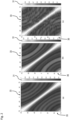
- Fig. 2 depicts simulated cosine coefficients for different conditions.
- the values of the cosine coefficients are represented by a varying brightness as indicated by the bars 31.
- a high brightness indicates an absolute value of the cosine coefficient close to one, whereas a low brightness indicates an absolute value of the cosine coefficient close to zero.
- the absolute value of the cosine coefficients is depicted depending from the angle of the ideal beam vector on the x-axis and depending from the angle of the simulated measured beam vector on the y-axis. That is, all combinations for the azimuth angles have been simulated in order to generate all potential cosine coefficients. Therefore, the angle of the measured beam vector b and the angle of the ideal beam vector (see also formula 8) have been considered independently for the simulations.
- the radar sensor assumed for the simulations includes two transmission channels and four receiver channels, corresponding to a standard radar system known in the art.
- noise free conditions and an elevation angle of 0° have been assumed
- an elevation angle of 7° has been assumed
- a noise condition having a signal to noise ratio of 20 dB for the reflection at the target object 23 25 has been provided at an elevation angle of 0°.
- the aim of the simulation is to assess whether the method according to the disclosure is able to separate the two classes of target objects 23, 25, i.e. stationary objects 25 from moving objects 23 and outliers, for the different conditions.
- a high correlation value (or absolute value of the cosine coefficient) is expected on the diagonal of the "angle matrix", i.e. on the diagonal in the diagrams of Fig. 2 from the upper left corner to the lower right corner.
- the expected separation of the two classes is sufficient enough for the noise free condition ( Fig. 2(a) ), and with adding the elevation angle of 7° ( Fig. 2(b) ) as well as for the additional noise ( Fig.
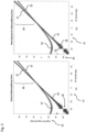
- Fig. 3 depicts a comparison between a classical stationary/moving check and a stationary/moving check based on the method according to the present disclosure.
- the results of the respective check i.e. the classification of target object 23, 25 as stationary or moving, is represented depending from the azimuth angle from classical angle finding (in degrees) on the x-axis and depending from the azimuth angle from range rate (in degrees) on the y-axis.
- the data as shown in Fig. 3 has been simulated for an ego or host vehicle 10 (see Fig. 1 ) having a velocity of 15 m/s, and for an additional moving target 23 having a velocity of 13 m/s and a yaw rate of 10 degrees/s.
- an ideal Doppler value and ideal beam vectors have been calculated for every possible angles of stationary target objects 25 and moving target objects 23.
- Gaussian noise has been added for both kinds of simulations.
- Fig. 3(a) For the classical approach providing the results of Fig. 3(a) , beam forming has been applied to the generated beam vectors for calculating the respective angles, and then the Doppler values have been used for applying the stationary/moving check. That is, the results as shown in Fig. 3(a) have been determined as described in context of formulas (1) to (3) above, i.e. the stationary/moving check has been performed based on the deviation between the actual Doppler and the expected Doppler. For the method according to the disclosure ( Fig. 3(b) ), the angles have been calculated backwards from the Doppler or range rate values, and the stationary/moving check has been applied to the beam vectors as described above in context of formulas (4) to (11).
- the target objects 25 classified as stationary are represented by the curve 45 close to the diagonal of the diagram from the lower left corner to the upper right corner.
- the gap shown at 46 is due to an area with low accuracy for the angle from range rate in the assumed driving direction of the vehicle 10.
- the target objects 23 classified as moving or outliers are represented by the curve 47 which generally should deviate from the diagonal of the diagram.
- the objects which should be classified as stationary are classified as moving, i.e. on the diagonal of the diagram, in addition to the objects for which the simulation results deviate from the diagonal.
- the target objects 25 classified as stationary are represented by the curve 51
- the target objects 23 classified as moving or outliers are represented by the curve 53.
- the method according to the disclosure can clearly distinguish between stationary and moving objects also in the region above 20 degrees.
- the method is also able to distinguish between stationary objects and outliers which are represented by the point clouds 55 on the right and left side of the curve 51 representing stationary target objects 25.
- artificial thin white lines are included between the points clouds 55 representing outliers or moving objects and the curve 51 representing stationary objects.
- the method according to the disclosure is able to overcome at least two drawbacks of the classical stationary/moving check, i.e. the false classification of stationary objects as moving, i.e. in the region 49 above 20 degrees, and the missing identification of outliers which are identified by the method according to the disclosure via the point clouds 55.
- the method according to the disclosure is also applied to a real data scenario for which radar data is acquired by a standard radar system which is installed in a vehicle.
- the observed real data scenario is shown in Fig. 4 , wherein in Fig. 4(a) depicts the view from the front of the vehicle, whereas Fig. 4(b) represents the view from the rear of the vehicle.
- the real data scenario includes moving vehicles, slowly moving pedestrians and stationary target objects in a city.
- six radars are installed at the vehicle.
- the respective boresight direction proceeds to the rear left, to the rear right, to the front right, to the front left, to the center left, and to the center right with respect to the vehicle.
- a corresponding diagram is shown in Fig. 5 for verifying the method according to the disclosure.
- Fig. 5 For the real data scenario of Fig. 4 , the results for applying the method according to the disclosure are shown in Fig. 5 .
- the classification of target objects 23, 25 is shown depending from the angle from range rate (in degrees) on the x-axis and depending from an angle determined by a Fourier transformation (in degrees) on the y-axis, i.e. an angle determined by classical angle finding as described above in context of Fig. 3 .
- the angle from range rate is denoted by 61
- the angle from the Fourier transform is denoted by 63.
- the six diagrams as shown in Fig. 5 are determined for different directions, i.e. for the rear left, for the rear right, for the front right, for the front left, for the center left, and for the center right when viewed from the vehicle.
- the target objects 25 classified as stationary are indicated by circles 65 (blue circles), whereas the target objects 23 classified as moving or outliers are represented by the circles 67 (red circles).
- the stationary objects 25 are located close to the diagonal of the diagram, as expected.
- the objects belonging to the circles 67 classified as moving or outliers are well separated from the diagonal and from the stationary objects.
- the circles 67 are likely to indicate moving objects if they are clustered in a region which has some distance to the diagonal, whereas the circles 67 are likely to indicate outliers if the circles 67 are separated from each other and single points.
- the method according to the disclosure is able to distinguish between stationary target objects 25 and moving target objects 23 properly also for the real data scenario.
- Fig. 6 shows a flow diagram 600 illustrating a method for determining a mobility status of a target object according to various embodiments.
- a detection angle of the target object may be determined.
- an ideal beam vector for a stationary object may be determined based on the detection angle.
- the ideal beam vector and a measured beam vector obtained from the data acquired by the sensor may be normalized.
- a correlation of the normalized ideal beam vector and the normalized measured beam vector may be determined.
- a score indicating whether the target object is stationary or moving may be determined based on the correlation of the normalized ideal and measured beam vectors.
- the senor may include a radar sensor and a range rate may be determined based on the data provided by the radar sensor.
- determining the detection angle of the target object may include solving an algebraic equation.
- a correlation of a beam vector derived from the sensor data and a reference vector may be used in order to resolve the ambiguity.
- the senor may include a radar sensor comprising a plurality of equally spaced antenna elements, and the ideal beam vector may depend on a ratio of the constant distance between the antenna elements and a wavelength of radar waves transmitted by the radar sensor.
- calculating the correlation of the normalized ideal and measured beam vectors may include calculating a cosine coefficient based on the normalized ideal beam vector and the normalized measured beam vector.
- a calibration matrix of the sensor may be applied to the measured beam vector before the measured beam vector is normalized.
- the target object may be determined to be stationary if the score is greater than a predetermined threshold.
- the at least one dynamic parameter may include a linear velocity and/or an angular velocity of the vehicle.
- Each of the steps 602, 604, 606, 608, 610 and the further steps described above may be performed by computer hardware components.
- Fig. 7 shows a system 700 for performing a stationary check according to various embodiments.
- the system 700 may implemented in the processing unit 15 (see Fig. 1 ) and may determine whether a target object is stationary or moving.
- the system 700 may include a detection angle determination circuit 702, an ideal beam vector prediction circuit 704, a normalizing circuit 706, a correlation determination circuit 708, and a score determination circuit 710.
- the detection angle determination circuit 702 may be configured to determine a detection angle of the target object.
- the ideal beam vector prediction circuit 704 may be configured to determine an ideal beam vector for a stationary object based on the detection angle.
- the normalizing circuit 706 may be configured to normalize the ideal beam vector and a measured beam vector obtained from the data acquired by the sensor.
- the correlation determination circuit 708 may be configured to determine a correlation of the normalized ideal beam vector and the normalized measured beam vector.
- the score determination circuit 710 may be configured to determine, based on the correlation of the normalized ideal and measured beam vectors, a score indicating whether the target object is stationary or moving.
- the detection angle determination circuit 702, the ideal beam vector prediction circuit 704, the normalizing circuit 706, the correlation determination circuit 708, and the score determination circuit 710 may be coupled with each other, e.g. via an electrical connection 712, such as e.g. a cable or a computer bus or via any other suitable electrical connection to exchange electrical signals.
- an electrical connection 712 such as e.g. a cable or a computer bus or via any other suitable electrical connection to exchange electrical signals.
- a “circuit” may be understood as any kind of a logic implementing entity, which may be special purpose circuitry or a processor executing a program stored in a memory, firmware, or any combination thereof.
- Fig. 8 depicts a computer system 800 with a plurality of computer hardware components configured to carry out steps of a computer implemented method for determining the stationarity of a target object according to various embodiments.
- the computer system 800 correspond to the computer system 11 as shown in Fig. 1 and may include a processor 802, a memory 804, and a non-transitory data storage 806.
- the radar sensor 13 (see Fig. 1 ) may be provided as part of the computer system 800 (like illustrated in Fig. 8 ), or may be provided external to the computer system 800.
- the processor 802, the memory 804 and the non-transitory data storage 806 may be components of the processing unit 15 (see Fig. 1 ).
- the processor 802 may carry out instructions provided in the memory 804.
- the non-transitory data storage 806 may store a computer program, including the instructions that may be transferred to the memory 804 and then executed by the processor 802.
- the radar sensor 13 may be used for acquiring radar sensor data, based on which a range rate may be acquired.
- the processor 802, the memory 804, and the non-transitory data storage 806 may be coupled with each other, e.g. via an electrical connection 810, such as e.g. a cable or a computer bus or via any other suitable electrical connection to exchange electrical signals.
- the radar sensor 13 may be coupled to the computer system 800, for example via an external interface, or may be provided as parts of the computer system (in other words: internal to the computer system, for example coupled via the electrical connection 810).
- Coupled or “connection” are intended to include a direct “coupling” (for example via a physical link) or direct “connection” as well as an indirect “coupling” or indirect “connection” (for example via a logical link), respectively.
Landscapes
- Engineering & Computer Science (AREA)
- Radar, Positioning & Navigation (AREA)
- Remote Sensing (AREA)
- Physics & Mathematics (AREA)
- Computer Networks & Wireless Communication (AREA)
- General Physics & Mathematics (AREA)
- Electromagnetism (AREA)
- Radar Systems Or Details Thereof (AREA)
Abstract
Description
- The present disclosure relates to methods and systems for determining the mobility status of a target object, i.e. for determining whether a target object is stationary or moving.
- When processing radar detections provided by a radar system, it is often a prerequisite for proper results that the detections originate from stationary targets. In other words, it may be required to distinguish whether a radar detection is provided by a stationary or a moving target. One application which is based on detections from stationary targets is estimating an azimuth angle from a range rate (AFRR) provided by the radar system.
- Detections from moving and stationary targets are usually distinguished by comparing a measured range rate with an expected range rate from a stationary target. If the deviation between the actual and expected range rates is smaller than a predetermined threshold, the radar detection is regarded as originating from a stationary target. However, estimating the expected range rate requires determining the azimuth angle of the target object under consideration. Therefore, performing a "full classical" angle finding method may be required to carry out such a stationary versus moving check for the target object. The full classical angle finding methods may rely on Fourier transform techniques or on an iterative adaptive approach (IAA), amongst others.
- Besides, radar angle finding usually needs some kind of ground truth measurement of the angle which may be performed in an anechoic chamber. However, measurements in such an anechoic chamber are usually cumbersome. In addition, the characteristics of the radar system may be affected if the radar system is mounted in a vehicle after the calibration in the anechoic chamber.
- Accordingly, there is a need to provide a method and a system for determining the mobility status of a target object without performing a full classical angle finding algorithm.
- The present disclosure provides a computer implemented method, a computer system and a non-transitory computer readable medium according to the independent claims. Exemplary embodiments are given in the subclaims, the description and the drawings.
- In one aspect, the present disclosure is directed at a computer implemented method for determining a mobility status of a target object located in an environment of a sensor configured to monitor a surrounding environment of a vehicle. The method comprises the following steps performed by computer hardware components: determining a detection angle of the target object with respect to the sensor based on data acquired by the sensor; predicting an ideal beam vector for a stationary object based on the detection angle; normalizing the ideal beam vector and a measured beam vector which is obtained from the data acquired by the sensor; determining a correlation of the normalized ideal beam vector and the normalized measured beam vector; and determining, based on the correlation of the normalized ideal and measured beam vectors, a score indicating whether the target object is stationary or moving.
- The sensor may be a radar sensor, and the detection angle may be the azimuth angle with respect to a boresight direction of the sensor. Further, the target object may be located in an external environment of a host vehicle in which the sensor is installed, and the sensor may therefore be configured to monitor the environment of the host vehicle.
- For performing the method, the detection angle may be determined e.g. based on a range rate or "Doppler" which is given as the negative value of the range rate provided by sensor detections, e.g. radar detections. As a result, the computational effort required for angle detection may be reduced in comparison to the classical angle finding methods. For the detection angle determined according to the proposed method, the ideal beam vector is predicted and correlated with the beam vector based on the data acquired by the sensor, wherein such a measured beam vector may be provided e.g. by a Fourier transform of the sensor detections as is known in the field of radar technology. Based on this correlation of the beam vectors, the score is determined as a measure for the target object to be stationary. In a similar manner as a probability, a score being greater than a first threshold, e.g. close to 1, may indicate that the target object is stationary, whereas a score which is lower than a second threshold being equal to or smaller than the first threshold, e.g. close to 0, may indicate that the target object is not stationary, e.g. a moving object or an outlier. A stationary target object may be assumed if the score exceeds a predefined value. In summary, the method requires a low computational effort since the stationary/moving test mostly relies on the correlation of the ideal and measured beam vectors determined for the target object. The result of the method, i.e. the information whether the target object is stationary or moving, may be used by further applications which are installed e.g. in a vehicle. Such applications may include angle finding from range rate (AFFR).
- According to an embodiment, the sensor may include a radar sensor, and the sensor data may include a range rate determined based on radar detections of the radar sensor. The detection angle of the target object may therefore be determined in a direct and efficient way.
- According to a further embodiment, the detection angle of the target object may be determined by solving an algebraic equation, leading to a further reduction of the computational effort of the method.
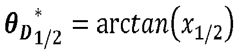
- The algebraic equation for determining the detection or azimuth angle θD may be based on the following equation for a Doppler d (which is given as the negative value of the range rate), wherein


- With the substitution θ := arctan (x) and the identity


- This may lead to the quadratic equation:

- Applying standard p-q-formulae to solve for x and some simplifications may result in:

- It is necessary to check for


- An ambiguity may be determined for the solution of the algebraic equation. If such an ambiguity is determined, a correlation of a beam vector derived from sensor data and of a reference vector may be used in order to resolve the ambiguity. By resolving the ambiguity, the reliability of the method may be further improved. The reference vector may include data based from a reflection point originating from a predetermined axis, e.g. at boresight with respect to the sensor.
- According to a further embodiment, the sensor may include a radar sensor comprising a plurality of equally spaced antenna elements. The ideal beam vector may depend on a ratio of the constant distance between the antenna elements and a wavelength of radar waves transmitted by the radar sensor. Moreover, a product of the ratio and the sine of the detection angle may define a phase relationship between components of the ideal beam vector. Therefore, predicting the ideal beam vector may be performed in an efficient manner with low computational effort.
- Calculating the correlation of the normalized ideal and measured beam vectors may include calculating a cosine coefficient based on the normalized ideal beam vector and the normalized measured beam vector. Before normalizing the measured beam vector and calculating the cosine coefficient, a calibration matrix of the sensor may be applied to the measured beam vector. The measured beam vector may be multiplied by the calibration matrix and normalized thereafter, and an inner product of the result and the ideal beam vector may be calculated in order to provide the cosine coefficient.
- The calibration matrix may be determined based on an initial diagonal calibration matrix which may be determined empirically, e.g. in an anechoic chamber at an azimuth angle of zero degree. Alternatively, the calibration matrix may be initialized via statistical methods. In both cases, the calibration matrix may be available for the method, e.g. by obtaining the calibration matrix from a database where the calibration matrix is stored after performing one of the calibration procedures.
- The absolute value of the cosine coefficient may directly provide the score for the target object being stationary. In detail, the score may be equal to the absolute value of the cosine coefficient. The target object may be determined to be stationary if the score or the absolute value of the cosine coefficient is greater than a predetermined threshold. The threshold may include a value of approximately 0.9 such that the threshold may be in a range e.g. from 0.88 to 0.92. By the threshold for the score or absolute value of the cosine coefficient, two classes of target objects may be defined, i.e. one class for stationary objects and one class for moving objects or outliers. Hence, it may be decided in an efficient manner based on the absolute value of the cosine coefficient and the threshold whether the target object is stationary or moving.
- According to a further embodiment, it may be determined for a plurality of detected target objects whether each of the respective target objects is stationary, and based on the number of detected stationary target objects, at least one dynamic parameter of a vehicle at which the sensor is installed may be determined. For example, the ego-motion of the vehicle may be determined based on the target objects which are determined to be stationary, while moving target objects or outliers are not considered. The at least one dynamic parameter may include a linear velocity and/or an angular velocity of the vehicle.
- In another aspect, the present disclosure is directed at a computer system, said computer system comprising a plurality of computer hardware components configured to carry out several or all steps of the computer implemented method described herein. Therefore, the benefits, the advantages and the disclosure as described above for the method are also valid for the computer system.
- The computer system may comprise a plurality of computer hardware components, for example a processor, a processing unit or a processing network, at least one memory, for example a memory unit or a memory network, and at least one non-transitory data storage. It will be understood that further computer hardware components may be provided and used for carrying out steps of the computer implemented method in the computer system. The non-transitory data storage and/or the memory unit may comprise a computer program for instructing the computer to perform several or all steps or aspects of the computer implemented method described herein, for example using the processing unit and the at least one memory unit.
- According to another aspect, the computer system further comprises: a radar sensor configured to acquire radar detections; wherein the computer system is configured to determine a range rate based on the radar detections; and wherein the computer system is configured to determine a measured beam vector based on the radar detections.
- According to another aspect, the radar sensor comprises a plurality of antenna elements, for example arranged as an antenna array.
- In another aspect, the present disclosure is directed at a vehicle comprising the computer system as described herein; and a radar sensor.
- As used herein, the terms processing device and processing unit may refer to, be part of, or include an Application Specific Integrated Circuit (ASIC); an electronic circuit; a combinational logic circuit; a field programmable gate array (FPGA); a processor (shared, dedicated, or group) that executes code; other suitable components that provide the described functionality; or a combination of some or all of the above, such as in a system-on-chip. The processing device and the processing unit may include memory (shared, dedicated, or group) that stores code executed by the processor.
- In another aspect, the present disclosure is directed at a non-transitory computer readable medium comprising instructions for carrying out several or all steps or aspects of the computer implemented method described herein. The computer readable medium may be configured as: an optical medium, such as a compact disc (CD) or a digital versatile disk (DVD); a magnetic medium, such as a hard disk drive (HDD); a solid state drive (SSD); a read only memory (ROM); a flash memory; or the like. Furthermore, the computer readable medium may be configured as a data storage that is accessible via a data connection, such as an internet connection. The computer readable medium may, for example, be an online data repository or a cloud storage.
- The present disclosure is also directed at a computer program for instructing a computer to perform several or all steps or aspects of the computer implemented method described herein.
- Exemplary embodiments and functions of the present disclosure are described herein in conjunction with the following drawings, showing schematically:
- Fig. 1
- a vehicle including a computer system configured to carry out a method according to the disclosure,
- Fig. 2
- simulation results for a cosine coefficient under different conditions,
- Fig. 3
- a comparison of a classical stationary/moving check using full angle finding versus a stationary/moving check using the method according to the disclosure,
- Fig. 4
- two pictures as an example for a real data scenario,
- Fig. 5
- results of the stationary/moving check using the method according to the disclosure for the real data scenario as shown in
Fig. 4 , - Fig. 6
- a flow diagram illustrating a method for determining a mobility status of a target object according to various embodiments,
- Fig. 7
- a system for a stationary check according to various embodiments, and
- Fig. 8
- a computer system with a plurality of computer hardware components configured to carry out steps of a computer implemented method for determining a mobility status of a target object according to various embodiments.
-
Fig. 1 depicts avehicle 10 including acomputer system 11 for carrying out a method for determining a mobility status of a target object, i.e. for determining whether a target object is stationary or moving. Thecomputer system 11 includes aradar sensor 13 and aprocessing unit 15 which is connected to theradar sensor 13 and configured to receive data acquired by theradar sensor 13 and to analyze these data according to the steps of the method. - Relative to the
radar sensor 13, a sensor-based coordinatesystem 17 is defined which includes anx-axis 19 and a y-axis 21, wherein thex-axis 19 coincides with the longitudinal axis of thevehicle 10, whereas the y-axis 21 coincides with the lateral axis with respect to thevehicle 10. - The
radar sensor 13 is configured to transmit radar waves and to provide radar detections rdet which originate from radar waves being reflected bytarget objects objects 23, like other vehicles, and a class forstationary objects 25, like buildings etc. - For some radar-based applications, it is important to distinguish between radar detections rdet originating from stationary target objects 25 and radar detections rdet originating from moving target objects 23 or outliers. For example, determining a detection or azimuth angle from range rate (AFRR) requires stationary target objects 25.
- Classically, moving and stationary detections are distinguished by comparing the actual Doppler d act (or range rate) and the Doppler d (or range rate) that is expected for a stationary detection. It is noted that the term "Doppler" stands for the negative value of the range rate. The calculation of d, however, requires the azimuth angle θ of a radar detection and the velocity vector as well as the yaw rate, i.e. (vveh, ω), of the
host vehicle 10 with the equation
radar sensor 13, and
radar sensor 13 in a vehicle coordinate system. - Using a rotation matrix Rθ
M of the mounting orientation θM of theradar sensor 13 with respect to the longitudinal axis of thehost vehicle 10, one can calculate the velocity vector
radar sensor 13 in the sensor coordinate system 17:

- If the deviation between the actual Doppler d act and the expected Doppler d is lower than a predefined threshold T, i.e. |d - dact | < T, the detection is considered as stationary, i.e. originating from a
stationary target object 25. However, without applying e.g. a classical full angle finding algorithm, the angle θ is unknown and this kind of stationary/moving check is not applicable. - Hence, the present disclosure provides a method for determining whether a target object is stationary or moving, wherein the method includes five basic steps described below. As an input, the method requires a measured beam vector b and a related Doppler d (or range rate) which are based on radar detections provided by the radar sensor 13 (see
Fig. 1 ). In addition, information about the motion of thehost vehicle 10 is required, i.e. its velocity and its yaw rate. - A first step includes calculating a detection or azimuth angle θD from the Doppler d using the motion of the host vehicle.
- Although other geometric and numerical methods may be applied for determining the azimuth angle θD based on the radar detections, for the present embodiment the following algebraic equation is solved for the azimuth angle θD (wherein


- With the substitution θ := arctan (x) and the identity


- This leads to a quadratic equation:

- Applying standard p-q-formulae to solve for x and some simplifications result in:

- It is necessary to check for


- Since a quadratic equation is solved in order to determine θD , there are usually two ambiguous solutions. This ambiguity can be resolved by considering a correlation between the measured beam vector b and a reference vector which includes data based from a reflection point originating from a predetermined axis, e.g. at boresight with respect to the
radar sensor 13. After resolving the ambiguity of the solutions of the quadratic equation, the final θD is received. Strictly speaking, this detection angle θD is valid for detections from stationary target objects 25 only. Therefore, the further method steps are performed in order to determine a measure or degree for θD and the underlying radar detection rdet originating from astationary target object 25. - As a second method step, an ideal beam vector is predicted for the detection angle θD . For the present embodiment, the ideal beam vector is given by:

radar sensor 13, and d is the ratio of a distance between the antenna elements and the wavelength of the radar waves which are transmitted by theradar sensor 13. It is assumed that the n antenna elements of theradar sensor 13 are equally spaced, i.e. that they have a constant distance therebetween. - It is noted that the number n of the antenna elements may not only represent a number of "real" physical antennas belonging to the
radar system 13, but also a number of virtual antennas for which the respective beam vectors may be defined, as is known in the art. Generally, the components of the beam vectors are based on a Fourier transform of raw data received by the respective real or virtual antennas. - In a third step, the measured beam vector b is calibrated. That is, the measured beam vector b which is based on the raw radar detection rdet for a given point in time is calibrated by multiplying the normalized beam vector by a calibration matrix C which reflects the characteristics of the
radar sensor 13. The calibration matrix C may be based on an initial diagonal calibration matrix which is determined e.g. by a measurement in an anechoic chamber using a measured beam vector at an azimuth angle of zero degrees only. Alternatively, an algorithm for initializing the calibration matrix C may be used which is based on statistical methods. - Thereafter, the ideal beam vector aideal and the calibrated measured beam vector are normalized as follows:

- The denominators on the right side of these formulas denote the usual Euclidean norm of the respective vectors. The normalization of the vectors is necessary since the phase or cosine coefficient between these vectors has to be considered for the stationary check as described in the following.
- As an alternative to multiplying the calibration matrix and the measured beam vector, the ideal beam vector and the calibration matrix may be multiplied before the normalization. This may save computational effort if similar values for the Doppler occur which are related to the respective radar detection rdet, i.e. if similar Doppler values are determined for different range bins.
- In a fourth step, a cosine coefficient is calculated for the beam vectors as a correlation between these as follows:

- The values of ψ lie in the interval of [0, 1] and can be interpreted as a score for the
target object 23, 25 (from which the respective radar detection rdet originates) being astationary target object 25. In a similar manner as a probability, a score being close to 1 indicates that thetarget object 25 is stationary, whereas a low score (e.g. being close to 0) indicates that thetarget object 25 is not stationary, i.e. a moving object or an outlier. - As a fifth step, the score ψ is compared with a threshold τ in order to assign the respective radar detection rdet and the
corresponding target object 23, 25 (seeFig. 1 ) to a class S of stationary target objects 25 or to a class M of moving target objects 23 or outliers. This can be described mathematically as follows:
- A suitable value for τ can be determined empirically and is typically about 0.9, e.g. 0.92.
- The results of the method may be applied for estimating the ego-motion of the
vehicle 10. The term "ego-motion" includes the linear velocity and the angular velocity of thehost vehicle 10 as part of its dynamic variables. - As described e.g. in
US 2019/0369222 A1 , measurements of the angle from range rate (AFRR) may be used in order to estimate the ego-motion by solving a linear equation system which is similar to the equations (1) to (3) mentioned above. However, detections from stationary target objects 25 have to be assumed since moving target objects 23 or noise may lead to substantial errors in the estimation. Therefore, estimating the ego-motion is typically embedded into an iterative approach in order to filter out moving target objects 23 and/or outliers. The known approach as described in the reference mentioned above is typically based on a direct angle measurement and a threshold based on the Doppler or range rate. The approach as described in this reference is called "random sample consensus (RANSAC)" calculation. - The results of the method for determining a mobility status of a target object according to the disclosure can be used to modify and simplify the known RANSAC approach. In detail, three radar detections are selected randomly, and the ego-motion is estimated based on these detections. Thereafter, the first four steps of the method as described above are performed for all radar detections, i.e. up to calculating the cosine coefficient. Thereafter, a threshold is applied to the cosine coefficients in order to determine the number of "inliers" i.e. the number of stationary target objects 25 with respect to the three randomly selected detections. These steps are repeated iteratively starting with the selection of three random detections, and the number of inliers is determined for each iteration. Finally, the iteration having the most inliers is stored as the result for estimating the ego-motion of the
vehicle 10. As an optional step, the ego-motion may be estimated for all final inliers. - In order to verify the method according to the disclosure, different simulations and experiments have been performed based on simulated and real data. The results of the simulations and experiments are depicted in
Figs. 2 to 5 . -
Fig. 2 depicts simulated cosine coefficients for different conditions. The values of the cosine coefficients are represented by a varying brightness as indicated by thebars 31. A high brightness indicates an absolute value of the cosine coefficient close to one, whereas a low brightness indicates an absolute value of the cosine coefficient close to zero. The absolute value of the cosine coefficients is depicted depending from the angle of the ideal beam vector on the x-axis and depending from the angle of the simulated measured beam vector on the y-axis. That is, all combinations for the azimuth angles have been simulated in order to generate all potential cosine coefficients. Therefore, the angle of the measured beam vector b and the angle of the ideal beam vector (see also formula 8) have been considered independently for the simulations. - The radar sensor assumed for the simulations includes two transmission channels and four receiver channels, corresponding to a standard radar system known in the art. For the data as shown in
Fig. 2(a) , noise free conditions and an elevation angle of 0° have been assumed, whereas for the results as shown inFig. 2(b) an elevation angle of 7° has been assumed, and for the results ofFig. 2(c) a noise condition having a signal to noise ratio of 20 dB for the reflection at thetarget object - The aim of the simulation is to assess whether the method according to the disclosure is able to separate the two classes of target objects 23, 25, i.e.
stationary objects 25 from movingobjects 23 and outliers, for the different conditions. In an ideal case, a high correlation value (or absolute value of the cosine coefficient) is expected on the diagonal of the "angle matrix", i.e. on the diagonal in the diagrams ofFig. 2 from the upper left corner to the lower right corner. As can be seen in all three diagrams ofFig. 2 , the expected separation of the two classes is sufficient enough for the noise free condition (Fig. 2(a) ), and with adding the elevation angle of 7° (Fig. 2(b) ) as well as for the additional noise (Fig. 2(c) ) since high absolute values for the cosine coefficient occur close to the diagonal of the respective diagram only. Due to these results, it is possible to perform the method according to the disclosure also on sub-arrays of the full antenna array of the radar sensor in order to get full independence from the elevation angle. -
Fig. 3 depicts a comparison between a classical stationary/moving check and a stationary/moving check based on the method according to the present disclosure. The results of the respective check, i.e. the classification oftarget object - The data as shown in
Fig. 3 has been simulated for an ego or host vehicle 10 (seeFig. 1 ) having a velocity of 15 m/s, and for an additional movingtarget 23 having a velocity of 13 m/s and a yaw rate of 10 degrees/s. For the simulations, an ideal Doppler value and ideal beam vectors have been calculated for every possible angles of stationary target objects 25 and moving target objects 23. Gaussian noise has been added for both kinds of simulations. - For the classical approach providing the results of
Fig. 3(a) , beam forming has been applied to the generated beam vectors for calculating the respective angles, and then the Doppler values have been used for applying the stationary/moving check. That is, the results as shown inFig. 3(a) have been determined as described in context of formulas (1) to (3) above, i.e. the stationary/moving check has been performed based on the deviation between the actual Doppler and the expected Doppler. For the method according to the disclosure (Fig. 3(b) ), the angles have been calculated backwards from the Doppler or range rate values, and the stationary/moving check has been applied to the beam vectors as described above in context of formulas (4) to (11). - In
Fig. 3(a) , the target objects 25 classified as stationary are represented by thecurve 45 close to the diagonal of the diagram from the lower left corner to the upper right corner. The gap shown at 46 is due to an area with low accuracy for the angle from range rate in the assumed driving direction of thevehicle 10. The target objects 23 classified as moving or outliers are represented by thecurve 47 which generally should deviate from the diagonal of the diagram. However, in the range starting from about 20 degrees, i.e. in the region denoted by 49, the objects which should be classified as stationary are classified as moving, i.e. on the diagonal of the diagram, in addition to the objects for which the simulation results deviate from the diagonal. - In
Fig. 3(b) , the target objects 25 classified as stationary are represented by thecurve 51, whereas the target objects 23 classified as moving or outliers are represented by thecurve 53. As can be seen in the region denoted by 49, the method according to the disclosure can clearly distinguish between stationary and moving objects also in the region above 20 degrees. Furthermore, in the region below -40 degrees, the method is also able to distinguish between stationary objects and outliers which are represented by the point clouds 55 on the right and left side of thecurve 51 representing stationary target objects 25. For better orientation, artificial thin white lines are included between the points clouds 55 representing outliers or moving objects and thecurve 51 representing stationary objects. - In summary, the method according to the disclosure is able to overcome at least two drawbacks of the classical stationary/moving check, i.e. the false classification of stationary objects as moving, i.e. in the
region 49 above 20 degrees, and the missing identification of outliers which are identified by the method according to the disclosure via the point clouds 55. - In addition to the simulations, the method according to the disclosure is also applied to a real data scenario for which radar data is acquired by a standard radar system which is installed in a vehicle. The observed real data scenario is shown in
Fig. 4 , wherein inFig. 4(a) depicts the view from the front of the vehicle, whereasFig. 4(b) represents the view from the rear of the vehicle. As can be recognized inFig. 4 , the real data scenario includes moving vehicles, slowly moving pedestrians and stationary target objects in a city. In order to provide a circumferential view with respect to the vehicle, six radars are installed at the vehicle. For each of the six radars, the respective boresight direction proceeds to the rear left, to the rear right, to the front right, to the front left, to the center left, and to the center right with respect to the vehicle. For each of these directions, a corresponding diagram is shown inFig. 5 for verifying the method according to the disclosure. - For the real data scenario of
Fig. 4 , the results for applying the method according to the disclosure are shown inFig. 5 . For all diagrams ofFig. 5 , the classification of target objects 23, 25 is shown depending from the angle from range rate (in degrees) on the x-axis and depending from an angle determined by a Fourier transformation (in degrees) on the y-axis, i.e. an angle determined by classical angle finding as described above in context ofFig. 3 . The angle from range rate is denoted by 61, whereas the angle from the Fourier transform is denoted by 63. The six diagrams as shown inFig. 5 are determined for different directions, i.e. for the rear left, for the rear right, for the front right, for the front left, for the center left, and for the center right when viewed from the vehicle. - In each of these diagrams, the target objects 25 classified as stationary are indicated by circles 65 (blue circles), whereas the target objects 23 classified as moving or outliers are represented by the circles 67 (red circles). As can be recognized in all diagrams, the
stationary objects 25 are located close to the diagonal of the diagram, as expected. In contrast, the objects belonging to thecircles 67 classified as moving or outliers are well separated from the diagonal and from the stationary objects. Thecircles 67 are likely to indicate moving objects if they are clustered in a region which has some distance to the diagonal, whereas thecircles 67 are likely to indicate outliers if thecircles 67 are separated from each other and single points. In summary, the method according to the disclosure is able to distinguish between stationary target objects 25 and moving target objects 23 properly also for the real data scenario. -
Fig. 6 shows a flow diagram 600 illustrating a method for determining a mobility status of a target object according to various embodiments. At 602, a detection angle of the target object may be determined. At 604, an ideal beam vector for a stationary object may be determined based on the detection angle. At 606, the ideal beam vector and a measured beam vector obtained from the data acquired by the sensor may be normalized. At 608, a correlation of the normalized ideal beam vector and the normalized measured beam vector may be determined. At 610, a score indicating whether the target object is stationary or moving may be determined based on the correlation of the normalized ideal and measured beam vectors. - According to various embodiments, the sensor may include a radar sensor and a range rate may be determined based on the data provided by the radar sensor.
- According to various embodiments, determining the detection angle of the target object may include solving an algebraic equation.
- According to various embodiments, if an ambiguity may be determined for the solution of the algebraic equation, a correlation of a beam vector derived from the sensor data and a reference vector may be used in order to resolve the ambiguity.
- According to various embodiments, the sensor may include a radar sensor comprising a plurality of equally spaced antenna elements, and the ideal beam vector may depend on a ratio of the constant distance between the antenna elements and a wavelength of radar waves transmitted by the radar sensor.
- According to various embodiments, calculating the correlation of the normalized ideal and measured beam vectors may include calculating a cosine coefficient based on the normalized ideal beam vector and the normalized measured beam vector.
- According to various embodiments, a calibration matrix of the sensor may be applied to the measured beam vector before the measured beam vector is normalized.
- According to various embodiments, the target object may be determined to be stationary if the score is greater than a predetermined threshold.
- According to various embodiments, it may be determined for a plurality of detected target objects whether each of the respective target objects is stationary, and based on the number of detected stationary target objects, at least one dynamic parameter of a vehicle at which the sensor is installed may be determined.
- According to various embodiments, the at least one dynamic parameter may include a linear velocity and/or an angular velocity of the vehicle.
- Each of the
steps -
Fig. 7 shows asystem 700 for performing a stationary check according to various embodiments. Thesystem 700 may implemented in the processing unit 15 (seeFig. 1 ) and may determine whether a target object is stationary or moving. In detail, thesystem 700 may include a detectionangle determination circuit 702, an ideal beamvector prediction circuit 704, a normalizingcircuit 706, acorrelation determination circuit 708, and ascore determination circuit 710. - The detection
angle determination circuit 702 may be configured to determine a detection angle of the target object. The ideal beamvector prediction circuit 704 may be configured to determine an ideal beam vector for a stationary object based on the detection angle. The normalizingcircuit 706 may be configured to normalize the ideal beam vector and a measured beam vector obtained from the data acquired by the sensor. Thecorrelation determination circuit 708 may be configured to determine a correlation of the normalized ideal beam vector and the normalized measured beam vector. Thescore determination circuit 710 may be configured to determine, based on the correlation of the normalized ideal and measured beam vectors, a score indicating whether the target object is stationary or moving. - The detection
angle determination circuit 702, the ideal beamvector prediction circuit 704, the normalizingcircuit 706, thecorrelation determination circuit 708, and thescore determination circuit 710 may be coupled with each other, e.g. via anelectrical connection 712, such as e.g. a cable or a computer bus or via any other suitable electrical connection to exchange electrical signals. - A "circuit" may be understood as any kind of a logic implementing entity, which may be special purpose circuitry or a processor executing a program stored in a memory, firmware, or any combination thereof.
-
Fig. 8 depicts acomputer system 800 with a plurality of computer hardware components configured to carry out steps of a computer implemented method for determining the stationarity of a target object according to various embodiments. Thecomputer system 800 correspond to thecomputer system 11 as shown inFig. 1 and may include aprocessor 802, amemory 804, and anon-transitory data storage 806. The radar sensor 13 (seeFig. 1 ) may be provided as part of the computer system 800 (like illustrated inFig. 8 ), or may be provided external to thecomputer system 800. Theprocessor 802, thememory 804 and thenon-transitory data storage 806 may be components of the processing unit 15 (seeFig. 1 ). - The
processor 802 may carry out instructions provided in thememory 804. Thenon-transitory data storage 806 may store a computer program, including the instructions that may be transferred to thememory 804 and then executed by theprocessor 802. Theradar sensor 13 may be used for acquiring radar sensor data, based on which a range rate may be acquired. - The
processor 802, thememory 804, and thenon-transitory data storage 806 may be coupled with each other, e.g. via anelectrical connection 810, such as e.g. a cable or a computer bus or via any other suitable electrical connection to exchange electrical signals. Theradar sensor 13 may be coupled to thecomputer system 800, for example via an external interface, or may be provided as parts of the computer system (in other words: internal to the computer system, for example coupled via the electrical connection 810). - The terms "coupling" or "connection" are intended to include a direct "coupling" (for example via a physical link) or direct "connection" as well as an indirect "coupling" or indirect "connection" (for example via a logical link), respectively.
- It will be understood that what has been described for one of the methods above may analogously hold true for the
system 700 and/or for thecomputer system 800. -
- 10
- host vehicle
- 11
- computer system
- 13
- radar sensor
- 15
- processing unit
- 17
- sensor coordinate system
- 19
- x-axis
- 21
- y-axis
- 23
- moving object
- 25
- stationary object
- 31
- bar indicating the absolute value of the cosine coefficient
- 33
- angle of ideal beam vector
- 35
- angle of measured beam vector
- 41
- azimuth angle from angle finding
- 43
- azimuth angle from range rate
- 45
- stationary objects from classical check
- 46
- gap
- 47
- moving objects and outliers from classical check
- 49
- region with false classification of classical check
- 51
- stationary objects from check using the method according to the disclosure
- 53
- moving objects and outliers from the check using the method according to the disclosure
- 55
- point cloud of outliers
- 61
- angle from range rate
- 63
- angle from Fourier transform
- 65
- circles for classifying objects as stationary
- 67
- circles for classifying objects as moving or outliers
- 600
- flow diagram illustrating a method for determining a mobility status of a target object
- 602
- step of determining a detection angle of a target object with respect to a sensor based on data acquired by the sensor
- 604
- step of predicting an ideal beam vector for a stationary object based on the detection angle
- 606
- step of normalizing the ideal beam vector and a measured beam vector obtained from the data acquired by the sensor
- 608
- step of determining a correlation of the normalized ideal beam vector and the normalized measured beam vector
- 610
- step of determining, based on the correlation of the normalized ideal and measured beam vectors, a score indicating whether the target object is stationary or moving
- 700
- system for stationary check
- 702
- detection angle determination circuit
- 704
- ideal beam vector prediction circuit
- 706
- normalizing circuit
- 708
- correlation determination circuit
- 710
- score determination circuit
- 712
- connection
- 800
- computer system according to various embodiments
- 802
- processor
- 804
- memory
- 806
- non-transitory data storage
- 810
- connection
Claims (15)
- Computer implemented method for determining a mobility status of a target object (23, 25) located in an environment of a sensor (13) configured to monitor a surrounding environment of a vehicle (10),
the method comprising the steps of:determining (602) a detection angle of the target object (23, 25) with respect to the sensor (13) based on data acquired by the sensor (13),predicting (604) an ideal beam vector for a stationary object based on the detection angle,normalizing (606) the ideal beam vector and a measured beam vector obtained from the data acquired by the sensor (13),determining (608) a correlation of the normalized ideal beam vector and the normalized measured beam vector, anddetermining (610), based on the correlation of the normalized ideal and measured beam vectors, a score indicating whether the target object (23, 25) is stationary or moving. - Method according to claim 1, wherein
the sensor (13) includes a radar sensor (13) and a range rate is determined based on the data provided by the radar sensor (13). - Method according to claim 1 or 2, wherein
determining the detection angle of the target object (23, 25) includes solving an algebraic equation. - Method according to claim 3, wherein
if an ambiguity is determined for the solution of the algebraic equation, a correlation of a beam vector derived from the sensor data and of a reference vector is used in order to resolve the ambiguity. - Method according to anyone of the preceding claims, whereinthe sensor (13) includes a radar sensor (13) comprising a plurality of equally spaced antenna elements, andthe ideal beam vector depends on a ratio of the constant distance between the antenna elements and a wavelength of radar waves transmitted by the radar sensor (13).
- Method according to anyone of the preceding claims, wherein calculating the correlation of the normalized ideal and measured beam vectors includes calculating a cosine coefficient based on the normalized ideal beam vector and the normalized measured beam vector.
- Method according to anyone of the preceding claims, wherein
a calibration matrix of the sensor (13) is applied to the measured beam vector before the measured beam vector is normalized. - Method according to anyone of the preceding claims, wherein
the target object (23, 25) is determined to be stationary if the score is greater than a predetermined threshold. - Method according to claim 8, whereinfor a plurality of detected target objects (23, 25), it is determined whether each of the respective target objects is stationary, andbased on the number of detected stationary target objects (23, 25), at least one dynamic parameter of a vehicle (10) is determined at which the sensor (13) is installed.
- Method according to claim 9, wherein
the at least one dynamic parameter includes a linear velocity and/or an angular velocity of the vehicle. - Computer system (11, 800), the computer system (11) comprising a plurality of computer hardware components configured to carry out the computer implemented method of any one of claims 1 to 10.
- Computer system (11, 800) according to claim 11, further comprising:a radar sensor (13) configured to acquire radar detections;wherein the computer system (11) is configured to determine a range rate for the target object (23, 25) based on the radar detections; andwherein the computer system (11) is configured to determine a measured beam vector based on the radar detections.
- Computer system (11, 800) according to claim 12, wherein
the radar sensor (13) comprises a plurality of antenna elements. - Vehicle (10), comprising:the computer system (11, 800) according to any one of claims 11 to 13; anda radar sensor (13).
- Non-transitory computer readable medium comprising instructions for carrying out the computer implemented method of at least one of claims 1 to 10.
Priority Applications (3)
| Application Number | Priority Date | Filing Date | Title |
|---|---|---|---|
| EP21213425.8A EP4194885B1 (en) | 2021-12-09 | 2021-12-09 | Method for determining the mobility status of a target object |
| CN202211463480.6A CN116256713B (en) | 2021-12-09 | 2022-11-22 | Method for determining the mobility state of a target object |
| US18/063,557 US11789144B2 (en) | 2021-12-09 | 2022-12-08 | Method for determining the mobility status of a target object |
Applications Claiming Priority (1)
| Application Number | Priority Date | Filing Date | Title |
|---|---|---|---|
| EP21213425.8A EP4194885B1 (en) | 2021-12-09 | 2021-12-09 | Method for determining the mobility status of a target object |
Publications (2)
| Publication Number | Publication Date |
|---|---|
| EP4194885A1 true EP4194885A1 (en) | 2023-06-14 |
| EP4194885B1 EP4194885B1 (en) | 2025-10-15 |
Family
ID=78827512
Family Applications (1)
| Application Number | Title | Priority Date | Filing Date |
|---|---|---|---|
| EP21213425.8A Active EP4194885B1 (en) | 2021-12-09 | 2021-12-09 | Method for determining the mobility status of a target object |
Country Status (3)
| Country | Link |
|---|---|
| US (1) | US11789144B2 (en) |
| EP (1) | EP4194885B1 (en) |
| CN (1) | CN116256713B (en) |
Families Citing this family (5)
| Publication number | Priority date | Publication date | Assignee | Title |
|---|---|---|---|---|
| US12259464B2 (en) * | 2022-04-08 | 2025-03-25 | Qualcomm Incorporated | Radar map layer in a crowdsourced HD map |
| KR102871397B1 (en) * | 2022-10-24 | 2025-10-22 | 한국전자통신연구원 | Methods for filtering dynamic objects in radar-based ego-motion estimation |
| US20240427002A1 (en) * | 2023-06-21 | 2024-12-26 | Applied Concepts, Inc. | System and method of operation for near field auxiliary radar |
| CN117634531B (en) * | 2024-01-25 | 2024-04-12 | 南京楚航科技有限公司 | Data cascading vehicle-mounted 4D millimeter wave radar signal processing method and device |
| US20250350330A1 (en) * | 2024-05-08 | 2025-11-13 | Raytheon Company | Beamspace equalization with internal spatially diverse test targets |
Citations (3)
| Publication number | Priority date | Publication date | Assignee | Title |
|---|---|---|---|---|
| EP2390680A1 (en) * | 2010-05-26 | 2011-11-30 | Mitsubishi Electric Corporation | Angular velocity estimation apparatus, computer program, and angular velocity estimation method |
| EP3318889A1 (en) * | 2016-10-31 | 2018-05-09 | Delphi Technologies, Inc. | Automated vehicle radar system with self-calibration |
| US20190369222A1 (en) | 2018-05-30 | 2019-12-05 | Ford Global Technologies, Llc | Radar Odometry For Vehicle |
Family Cites Families (44)
| Publication number | Priority date | Publication date | Assignee | Title |
|---|---|---|---|---|
| US6873251B2 (en) | 2002-07-16 | 2005-03-29 | Delphi Technologies, Inc. | Tracking system and method employing multiple overlapping sensors |
| US9229102B1 (en) * | 2009-12-18 | 2016-01-05 | L-3 Communications Security And Detection Systems, Inc. | Detection of movable objects |
| CN102544755B (en) | 2011-12-31 | 2013-12-11 | 哈尔滨工业大学 | Uniform linear array calibration method based on strong scattering points |
| US20150070207A1 (en) * | 2013-09-06 | 2015-03-12 | Valeo Radar Systems, Inc. | Method and Apparatus For Self Calibration of A Vehicle Radar System |
| US9939522B2 (en) | 2013-10-13 | 2018-04-10 | Oculii Corp | Systems and methods for 4-dimensional radar tracking |
| JP6432221B2 (en) * | 2014-01-15 | 2018-12-05 | パナソニック株式会社 | Radar equipment |
| US9255988B2 (en) * | 2014-01-16 | 2016-02-09 | GM Global Technology Operations LLC | Object fusion system of multiple radar imaging sensors |
| JP6406601B2 (en) | 2014-08-05 | 2018-10-17 | パナソニックIpマネジメント株式会社 | Radar apparatus and object detection method |
| JP6548376B2 (en) | 2014-10-06 | 2019-07-24 | 日本電産株式会社 | Radar system, radar signal processing device, vehicle travel control device and method, and computer program |
| JP6567832B2 (en) | 2015-01-29 | 2019-08-28 | 日本電産株式会社 | Radar system, radar signal processing apparatus, vehicle travel control apparatus and method, and computer program |
| US9983301B2 (en) | 2015-10-02 | 2018-05-29 | Delphi Technologies, Inc. | Automated vehicle radar system to determine yaw-rate of a target vehicle |
| EP3252501B1 (en) | 2016-06-03 | 2022-06-08 | Veoneer Sweden AB | Enhanced object detection and motion state estimation for a vehicle environment detection system |
| JP2017223461A (en) * | 2016-06-13 | 2017-12-21 | パナソニックIpマネジメント株式会社 | Radar apparatus and detection method |
| WO2018013024A1 (en) | 2016-07-15 | 2018-01-18 | Telefonaktiebolaget Lm Ericsson (Publ) | Beam direction selection for a radio communications device |
| US10114106B2 (en) | 2016-07-22 | 2018-10-30 | Delphi Technologies, Inc. | Automated vehicle radar system with auto-alignment for azimuth, elevation, and vehicle speed-scaling-error |
| EP3285230B1 (en) | 2016-08-19 | 2021-04-07 | Veoneer Sweden AB | Enhanced object detection and motion estimation for a vehicle environment detection system |
| CN107783137B (en) | 2016-08-31 | 2021-07-13 | 北京自动化控制设备研究所 | An Acoustic Doppler and Acoustic Correlation Velocimetry Method Based on Five-beam Configuration |
| US10495753B2 (en) | 2016-09-19 | 2019-12-03 | Nec Corporation | Video to radar |
| US10591584B2 (en) | 2016-10-25 | 2020-03-17 | GM Global Technology Operations LLC | Radar calibration with known global positioning of static objects |
| JP6867184B2 (en) | 2017-02-13 | 2021-04-28 | トヨタ自動車株式会社 | Driving support device |
| US10690743B2 (en) | 2017-08-17 | 2020-06-23 | GM Global Technology Operations LLC | Doppler measurements to resolve angle of arrival ambiguity of wide aperture radar |
| EP3652721A1 (en) | 2017-09-04 | 2020-05-20 | NNG Software Developing and Commercial LLC | A method and apparatus for collecting and using sensor data from a vehicle |
| US20180024239A1 (en) * | 2017-09-25 | 2018-01-25 | GM Global Technology Operations LLC | Systems and methods for radar localization in autonomous vehicles |
| CN111819466B (en) | 2018-03-29 | 2024-10-18 | 索尼公司 | Device, system and method for locating an object in a scene |
| WO2019195327A1 (en) | 2018-04-05 | 2019-10-10 | Google Llc | Smart-device-based radar system performing angular estimation using machine learning |
| EP3572839A1 (en) * | 2018-05-23 | 2019-11-27 | Aptiv Technologies Limited | Method of estimating a velocity magnitude of a moving target in a horizontal plane and radar detection system |
| US11217012B2 (en) | 2018-11-16 | 2022-01-04 | Uatc, Llc | System and method for identifying travel way features for autonomous vehicle motion control |
| US11899099B2 (en) | 2018-11-30 | 2024-02-13 | Qualcomm Incorporated | Early fusion of camera and radar frames |
| US11927668B2 (en) | 2018-11-30 | 2024-03-12 | Qualcomm Incorporated | Radar deep learning |
| DE102018222800A1 (en) | 2018-12-21 | 2020-06-25 | Robert Bosch Gmbh | Locating and / or classifying objects from radar data with improved reliability at different distances |
| US12158518B2 (en) | 2019-01-07 | 2024-12-03 | Qualcomm Incorporated | Resolution of elevation ambiguity in one-dimensional radar processing |
| US11313950B2 (en) | 2019-01-15 | 2022-04-26 | Image Sensing Systems, Inc. | Machine learning based highway radar vehicle classification across multiple lanes and speeds |
| EP3702802A1 (en) | 2019-03-01 | 2020-09-02 | Aptiv Technologies Limited | Method of multi-sensor data fusion |
| EP3767325B1 (en) | 2019-07-19 | 2026-01-07 | Aptiv Technologies AG | Methods and systems for processing radar reflections |
| US11346933B2 (en) | 2019-07-24 | 2022-05-31 | GM Global Technology Operations LLC | Doppler ambiguity resolution in MIMO radars using a SIMO evaluation |
| US11520037B2 (en) | 2019-09-30 | 2022-12-06 | Zoox, Inc. | Perception system |
| WO2021116944A1 (en) * | 2019-12-09 | 2021-06-17 | Thales Canada Inc. | Stationary status resolution system |
| US20210208272A1 (en) | 2020-01-06 | 2021-07-08 | Tal Lavian | Radar target detection system for autonomous vehicles with ultra-low phase-noise frequency synthesizer |
| US11270170B2 (en) | 2020-03-18 | 2022-03-08 | GM Global Technology Operations LLC | Object detection using low level camera radar fusion |
| EP3943968A1 (en) | 2020-07-24 | 2022-01-26 | Aptiv Technologies Limited | Methods and system for detection of objects in a vicinity of a vehicle |
| EP3985410A1 (en) | 2020-10-15 | 2022-04-20 | Aptiv Technologies Limited | Methods and systems for calibrating a radar sensor |
| DE102020215424A1 (en) * | 2020-12-07 | 2022-06-09 | Robert Bosch Gesellschaft mit beschränkter Haftung | Method for determining an airspeed estimate and an angle estimate of targets |
| KR102288673B1 (en) | 2020-12-28 | 2021-08-12 | 주식회사 비트센싱 | Radar having antennas arranged in horizontal and vertical intervals |
| EP4033269B1 (en) | 2021-01-26 | 2025-11-12 | Aptiv Technologies AG | Methods and system for determining an angle of a detection |
-
2021
- 2021-12-09 EP EP21213425.8A patent/EP4194885B1/en active Active
-
2022
- 2022-11-22 CN CN202211463480.6A patent/CN116256713B/en active Active
- 2022-12-08 US US18/063,557 patent/US11789144B2/en active Active
Patent Citations (3)
| Publication number | Priority date | Publication date | Assignee | Title |
|---|---|---|---|---|
| EP2390680A1 (en) * | 2010-05-26 | 2011-11-30 | Mitsubishi Electric Corporation | Angular velocity estimation apparatus, computer program, and angular velocity estimation method |
| EP3318889A1 (en) * | 2016-10-31 | 2018-05-09 | Delphi Technologies, Inc. | Automated vehicle radar system with self-calibration |
| US20190369222A1 (en) | 2018-05-30 | 2019-12-05 | Ford Global Technologies, Llc | Radar Odometry For Vehicle |
Also Published As
| Publication number | Publication date |
|---|---|
| CN116256713B (en) | 2024-05-10 |
| EP4194885B1 (en) | 2025-10-15 |
| CN116256713A (en) | 2023-06-13 |
| US20230184932A1 (en) | 2023-06-15 |
| US11789144B2 (en) | 2023-10-17 |
Similar Documents
| Publication | Publication Date | Title |
|---|---|---|
| EP4194885B1 (en) | Method for determining the mobility status of a target object | |
| US12270892B2 (en) | Method and apparatus for processing radar signal by correcting phase distortion | |
| CN111352110B (en) | Method and device for processing radar data | |
| US6002983A (en) | Angle extent estimation method for a motor vehicle object detection system | |
| US11448746B2 (en) | Method of estimating a velocity magnitude of a moving target in a horizontal plane and radar detection system | |
| CN113050082B (en) | Method and device for processing radar signals | |
| CN111373282A (en) | Radar Processing Chain for FMCW Radar Systems | |
| EP3575827A1 (en) | Method for robust estimation of the velocity of a target using a host vehicle | |
| US12153158B2 (en) | Methods and systems for calibrating a radar sensor | |
| US11774574B2 (en) | Methods and system for determining an angle of a detection | |
| CN115932756A (en) | Method and system for calibrating radar sensors | |
| CN118191768A (en) | Method and device for radar signal processing, and radar array antenna | |
| EP4075164B1 (en) | Method and device for estimating a velocity of an object | |
| US12455347B2 (en) | Method and system for estimating a radar calibration matrix | |
| CN117665721A (en) | Methods and apparatus for radar signal processing | |
| EP4549992A1 (en) | Method for determining a pitch angle of an automobile radar | |
| CN119881824B (en) | A method for eliminating static targets based on RANSAC algorithm | |
| CN120178226A (en) | A millimeter wave radar tracking method in complex multi-target environment |
Legal Events
| Date | Code | Title | Description |
|---|---|---|---|
| PUAI | Public reference made under article 153(3) epc to a published international application that has entered the european phase |
Free format text: ORIGINAL CODE: 0009012 |
|
| STAA | Information on the status of an ep patent application or granted ep patent |
Free format text: STATUS: THE APPLICATION HAS BEEN PUBLISHED |
|
| AK | Designated contracting states |
Kind code of ref document: A1 Designated state(s): AL AT BE BG CH CY CZ DE DK EE ES FI FR GB GR HR HU IE IS IT LI LT LU LV MC MK MT NL NO PL PT RO RS SE SI SK SM TR |
|
| STAA | Information on the status of an ep patent application or granted ep patent |
Free format text: STATUS: REQUEST FOR EXAMINATION WAS MADE |
|
| 17P | Request for examination filed |
Effective date: 20231009 |
|
| RBV | Designated contracting states (corrected) |
Designated state(s): AL AT BE BG CH CY CZ DE DK EE ES FI FR GB GR HR HU IE IS IT LI LT LU LV MC MK MT NL NO PL PT RO RS SE SI SK SM TR |
|
| RAP1 | Party data changed (applicant data changed or rights of an application transferred) |
Owner name: APTIV TECHNOLOGIES AG |
|
| RAP3 | Party data changed (applicant data changed or rights of an application transferred) |
Owner name: APTIV TECHNOLOGIES AG |
|
| GRAP | Despatch of communication of intention to grant a patent |
Free format text: ORIGINAL CODE: EPIDOSNIGR1 |
|
| STAA | Information on the status of an ep patent application or granted ep patent |
Free format text: STATUS: GRANT OF PATENT IS INTENDED |
|
| INTG | Intention to grant announced |
Effective date: 20250519 |
|
| GRAS | Grant fee paid |
Free format text: ORIGINAL CODE: EPIDOSNIGR3 |
|
| GRAA | (expected) grant |
Free format text: ORIGINAL CODE: 0009210 |
|
| STAA | Information on the status of an ep patent application or granted ep patent |
Free format text: STATUS: THE PATENT HAS BEEN GRANTED |
|
| P01 | Opt-out of the competence of the unified patent court (upc) registered |
Free format text: CASE NUMBER: UPC_APP_3840_4194885/2025 Effective date: 20250820 |
|
| AK | Designated contracting states |
Kind code of ref document: B1 Designated state(s): AL AT BE BG CH CY CZ DE DK EE ES FI FR GB GR HR HU IE IS IT LI LT LU LV MC MK MT NL NO PL PT RO RS SE SI SK SM TR |
|
| REG | Reference to a national code |
Ref country code: GB Ref legal event code: FG4D Ref country code: CH Ref legal event code: F10 Free format text: ST27 STATUS EVENT CODE: U-0-0-F10-F00 (AS PROVIDED BY THE NATIONAL OFFICE) Effective date: 20251015 |
|
| REG | Reference to a national code |
Ref country code: IE Ref legal event code: FG4D |
|
| REG | Reference to a national code |
Ref country code: DE Ref legal event code: R096 Ref document number: 602021040356 Country of ref document: DE |
|
| PGFP | Annual fee paid to national office [announced via postgrant information from national office to epo] |
Ref country code: DE Payment date: 20251117 Year of fee payment: 5 |
|
| PGFP | Annual fee paid to national office [announced via postgrant information from national office to epo] |
Ref country code: GB Payment date: 20251107 Year of fee payment: 5 |
|
| PGFP | Annual fee paid to national office [announced via postgrant information from national office to epo] |
Ref country code: AT Payment date: 20260113 Year of fee payment: 5 |
|
| PGFP | Annual fee paid to national office [announced via postgrant information from national office to epo] |
Ref country code: FR Payment date: 20251112 Year of fee payment: 5 |
|
| REG | Reference to a national code |
Ref country code: NL Ref legal event code: MP Effective date: 20251015 |
|
| REG | Reference to a national code |
Ref country code: AT Ref legal event code: MK05 Ref document number: 1847377 Country of ref document: AT Kind code of ref document: T Effective date: 20251015 |
|
| PG25 | Lapsed in a contracting state [announced via postgrant information from national office to epo] |
Ref country code: NL Free format text: LAPSE BECAUSE OF FAILURE TO SUBMIT A TRANSLATION OF THE DESCRIPTION OR TO PAY THE FEE WITHIN THE PRESCRIBED TIME-LIMIT Effective date: 20251015 |
|
| PG25 | Lapsed in a contracting state [announced via postgrant information from national office to epo] |
Ref country code: ES Free format text: LAPSE BECAUSE OF FAILURE TO SUBMIT A TRANSLATION OF THE DESCRIPTION OR TO PAY THE FEE WITHIN THE PRESCRIBED TIME-LIMIT Effective date: 20251015 |
|
| REG | Reference to a national code |
Ref country code: LT Ref legal event code: MG9D |
|
| PG25 | Lapsed in a contracting state [announced via postgrant information from national office to epo] |
Ref country code: NO Free format text: LAPSE BECAUSE OF FAILURE TO SUBMIT A TRANSLATION OF THE DESCRIPTION OR TO PAY THE FEE WITHIN THE PRESCRIBED TIME-LIMIT Effective date: 20260115 |
|
| PG25 | Lapsed in a contracting state [announced via postgrant information from national office to epo] |
Ref country code: HR Free format text: LAPSE BECAUSE OF FAILURE TO SUBMIT A TRANSLATION OF THE DESCRIPTION OR TO PAY THE FEE WITHIN THE PRESCRIBED TIME-LIMIT Effective date: 20251015 Ref country code: FI Free format text: LAPSE BECAUSE OF FAILURE TO SUBMIT A TRANSLATION OF THE DESCRIPTION OR TO PAY THE FEE WITHIN THE PRESCRIBED TIME-LIMIT Effective date: 20251015 Ref country code: AT Free format text: LAPSE BECAUSE OF FAILURE TO SUBMIT A TRANSLATION OF THE DESCRIPTION OR TO PAY THE FEE WITHIN THE PRESCRIBED TIME-LIMIT Effective date: 20251015 |
|
| PG25 | Lapsed in a contracting state [announced via postgrant information from national office to epo] |
Ref country code: RS Free format text: LAPSE BECAUSE OF FAILURE TO SUBMIT A TRANSLATION OF THE DESCRIPTION OR TO PAY THE FEE WITHIN THE PRESCRIBED TIME-LIMIT Effective date: 20260115 |
|
| PG25 | Lapsed in a contracting state [announced via postgrant information from national office to epo] |
Ref country code: IS Free format text: LAPSE BECAUSE OF FAILURE TO SUBMIT A TRANSLATION OF THE DESCRIPTION OR TO PAY THE FEE WITHIN THE PRESCRIBED TIME-LIMIT Effective date: 20260215 |
|
| PG25 | Lapsed in a contracting state [announced via postgrant information from national office to epo] |
Ref country code: PT Free format text: LAPSE BECAUSE OF FAILURE TO SUBMIT A TRANSLATION OF THE DESCRIPTION OR TO PAY THE FEE WITHIN THE PRESCRIBED TIME-LIMIT Effective date: 20260216 |
|
| PG25 | Lapsed in a contracting state [announced via postgrant information from national office to epo] |
Ref country code: PL Free format text: LAPSE BECAUSE OF FAILURE TO SUBMIT A TRANSLATION OF THE DESCRIPTION OR TO PAY THE FEE WITHIN THE PRESCRIBED TIME-LIMIT Effective date: 20251015 |
|
| PG25 | Lapsed in a contracting state [announced via postgrant information from national office to epo] |
Ref country code: LV Free format text: LAPSE BECAUSE OF FAILURE TO SUBMIT A TRANSLATION OF THE DESCRIPTION OR TO PAY THE FEE WITHIN THE PRESCRIBED TIME-LIMIT Effective date: 20251015 |
|
| PG25 | Lapsed in a contracting state [announced via postgrant information from national office to epo] |
Ref country code: BG Free format text: LAPSE BECAUSE OF FAILURE TO SUBMIT A TRANSLATION OF THE DESCRIPTION OR TO PAY THE FEE WITHIN THE PRESCRIBED TIME-LIMIT Effective date: 20251015 |