EP4194868A1 - Discharge voltage graph prediction method and battery system using same - Google Patents
Discharge voltage graph prediction method and battery system using same Download PDFInfo
- Publication number
- EP4194868A1 EP4194868A1 EP21917932.2A EP21917932A EP4194868A1 EP 4194868 A1 EP4194868 A1 EP 4194868A1 EP 21917932 A EP21917932 A EP 21917932A EP 4194868 A1 EP4194868 A1 EP 4194868A1
- Authority
- EP
- European Patent Office
- Prior art keywords
- discharge
- voltage
- constant current
- battery cell
- time
- Prior art date
- Legal status (The legal status is an assumption and is not a legal conclusion. Google has not performed a legal analysis and makes no representation as to the accuracy of the status listed.)
- Granted
Links
Images


Classifications
-
- G—PHYSICS
- G01—MEASURING; TESTING
- G01R—MEASURING ELECTRIC VARIABLES; MEASURING MAGNETIC VARIABLES
- G01R31/00—Arrangements for testing electric properties; Arrangements for locating electric faults; Arrangements for electrical testing characterised by what is being tested not provided for elsewhere
- G01R31/36—Arrangements for testing, measuring or monitoring the electrical condition of accumulators or electric batteries, e.g. capacity or state of charge [SoC]
- G01R31/367—Software therefor, e.g. for battery testing using modelling or look-up tables
-
- H—ELECTRICITY
- H01—ELECTRIC ELEMENTS
- H01M—PROCESSES OR MEANS, e.g. BATTERIES, FOR THE DIRECT CONVERSION OF CHEMICAL ENERGY INTO ELECTRICAL ENERGY
- H01M10/00—Secondary cells; Manufacture thereof
- H01M10/42—Methods or arrangements for servicing or maintenance of secondary cells or secondary half-cells
-
- G—PHYSICS
- G01—MEASURING; TESTING
- G01R—MEASURING ELECTRIC VARIABLES; MEASURING MAGNETIC VARIABLES
- G01R19/00—Arrangements for measuring currents or voltages or for indicating presence or sign thereof
- G01R19/10—Measuring sum, difference or ratio
-
- G—PHYSICS
- G01—MEASURING; TESTING
- G01R—MEASURING ELECTRIC VARIABLES; MEASURING MAGNETIC VARIABLES
- G01R19/00—Arrangements for measuring currents or voltages or for indicating presence or sign thereof
- G01R19/175—Indicating the instants of passage of current or voltage through a given value, e.g. passage through zero
-
- G—PHYSICS
- G01—MEASURING; TESTING
- G01R—MEASURING ELECTRIC VARIABLES; MEASURING MAGNETIC VARIABLES
- G01R31/00—Arrangements for testing electric properties; Arrangements for locating electric faults; Arrangements for electrical testing characterised by what is being tested not provided for elsewhere
- G01R31/36—Arrangements for testing, measuring or monitoring the electrical condition of accumulators or electric batteries, e.g. capacity or state of charge [SoC]
- G01R31/3644—Constructional arrangements
- G01R31/3648—Constructional arrangements comprising digital calculation means, e.g. for performing an algorithm
-
- G—PHYSICS
- G01—MEASURING; TESTING
- G01R—MEASURING ELECTRIC VARIABLES; MEASURING MAGNETIC VARIABLES
- G01R31/00—Arrangements for testing electric properties; Arrangements for locating electric faults; Arrangements for electrical testing characterised by what is being tested not provided for elsewhere
- G01R31/36—Arrangements for testing, measuring or monitoring the electrical condition of accumulators or electric batteries, e.g. capacity or state of charge [SoC]
- G01R31/382—Arrangements for monitoring battery or accumulator variables, e.g. SoC
-
- G—PHYSICS
- G01—MEASURING; TESTING
- G01R—MEASURING ELECTRIC VARIABLES; MEASURING MAGNETIC VARIABLES
- G01R31/00—Arrangements for testing electric properties; Arrangements for locating electric faults; Arrangements for electrical testing characterised by what is being tested not provided for elsewhere
- G01R31/36—Arrangements for testing, measuring or monitoring the electrical condition of accumulators or electric batteries, e.g. capacity or state of charge [SoC]
- G01R31/385—Arrangements for measuring battery or accumulator variables
- G01R31/387—Determining ampere-hour charge capacity or SoC
-
- G—PHYSICS
- G01—MEASURING; TESTING
- G01R—MEASURING ELECTRIC VARIABLES; MEASURING MAGNETIC VARIABLES
- G01R31/00—Arrangements for testing electric properties; Arrangements for locating electric faults; Arrangements for electrical testing characterised by what is being tested not provided for elsewhere
- G01R31/36—Arrangements for testing, measuring or monitoring the electrical condition of accumulators or electric batteries, e.g. capacity or state of charge [SoC]
- G01R31/396—Acquisition or processing of data for testing or for monitoring individual cells or groups of cells within a battery
-
- H—ELECTRICITY
- H01—ELECTRIC ELEMENTS
- H01M—PROCESSES OR MEANS, e.g. BATTERIES, FOR THE DIRECT CONVERSION OF CHEMICAL ENERGY INTO ELECTRICAL ENERGY
- H01M10/00—Secondary cells; Manufacture thereof
- H01M10/42—Methods or arrangements for servicing or maintenance of secondary cells or secondary half-cells
- H01M10/48—Accumulators combined with arrangements for measuring, testing or indicating the condition of cells, e.g. the level or density of the electrolyte
-
- H—ELECTRICITY
- H02—GENERATION; CONVERSION OR DISTRIBUTION OF ELECTRIC POWER
- H02J—ELECTRIC POWER NETWORKS; CIRCUIT ARRANGEMENTS OR SYSTEMS FOR SUPPLYING OR DISTRIBUTING ELECTRIC POWER; SYSTEMS FOR STORING ELECTRIC ENERGY
- H02J7/00—Circuit arrangements for charging or discharging batteries or for supplying loads from batteries
- H02J7/80—Circuit arrangements for charging or discharging batteries or for supplying loads from batteries including monitoring or indicating arrangements
- H02J7/82—Control of state of charge [SOC]
-
- H—ELECTRICITY
- H02—GENERATION; CONVERSION OR DISTRIBUTION OF ELECTRIC POWER
- H02J—ELECTRIC POWER NETWORKS; CIRCUIT ARRANGEMENTS OR SYSTEMS FOR SUPPLYING OR DISTRIBUTING ELECTRIC POWER; SYSTEMS FOR STORING ELECTRIC ENERGY
- H02J7/00—Circuit arrangements for charging or discharging batteries or for supplying loads from batteries
- H02J7/855—Circuit arrangements for charging or discharging batteries or for supplying loads from batteries with circuits adapted for supplying loads from the battery
-
- H—ELECTRICITY
- H02—GENERATION; CONVERSION OR DISTRIBUTION OF ELECTRIC POWER
- H02J—ELECTRIC POWER NETWORKS; CIRCUIT ARRANGEMENTS OR SYSTEMS FOR SUPPLYING OR DISTRIBUTING ELECTRIC POWER; SYSTEMS FOR STORING ELECTRIC ENERGY
- H02J7/00—Circuit arrangements for charging or discharging batteries or for supplying loads from batteries
- H02J7/90—Regulation of charging or discharging current or voltage
- H02J7/94—Regulation of charging or discharging current or voltage in response to battery current
-
- H—ELECTRICITY
- H02—GENERATION; CONVERSION OR DISTRIBUTION OF ELECTRIC POWER
- H02J—ELECTRIC POWER NETWORKS; CIRCUIT ARRANGEMENTS OR SYSTEMS FOR SUPPLYING OR DISTRIBUTING ELECTRIC POWER; SYSTEMS FOR STORING ELECTRIC ENERGY
- H02J7/00—Circuit arrangements for charging or discharging batteries or for supplying loads from batteries
- H02J7/90—Regulation of charging or discharging current or voltage
- H02J7/96—Regulation of charging or discharging current or voltage in response to battery voltage
-
- H—ELECTRICITY
- H01—ELECTRIC ELEMENTS
- H01M—PROCESSES OR MEANS, e.g. BATTERIES, FOR THE DIRECT CONVERSION OF CHEMICAL ENERGY INTO ELECTRICAL ENERGY
- H01M10/00—Secondary cells; Manufacture thereof
- H01M10/42—Methods or arrangements for servicing or maintenance of secondary cells or secondary half-cells
- H01M10/425—Structural combination with electronic components, e.g. electronic circuits integrated to the outside of the casing
- H01M2010/4271—Battery management systems including electronic circuits, e.g. control of current or voltage to keep battery in healthy state, cell balancing
-
- Y—GENERAL TAGGING OF NEW TECHNOLOGICAL DEVELOPMENTS; GENERAL TAGGING OF CROSS-SECTIONAL TECHNOLOGIES SPANNING OVER SEVERAL SECTIONS OF THE IPC; TECHNICAL SUBJECTS COVERED BY FORMER USPC CROSS-REFERENCE ART COLLECTIONS [XRACs] AND DIGESTS
- Y02—TECHNOLOGIES OR APPLICATIONS FOR MITIGATION OR ADAPTATION AGAINST CLIMATE CHANGE
- Y02E—REDUCTION OF GREENHOUSE GAS [GHG] EMISSIONS, RELATED TO ENERGY GENERATION, TRANSMISSION OR DISTRIBUTION
- Y02E60/00—Enabling technologies; Technologies with a potential or indirect contribution to GHG emissions mitigation
- Y02E60/10—Energy storage using batteries
Definitions
- the present disclosure relates to a discharge voltage graph prediction method and a battery system using the same.
- the discharge voltage graph is a graph of the change in the battery cell voltage depending on a passage of time when being discharged with a predetermined constant current, it is necessary to measure a discharge limit current at a predetermined time, a discharge resistance at a predetermined time, or a discharge power at a predetermined time.
- the present disclosure is to provide a discharge voltage graph prediction method that may predict the discharge voltage graph and a battery system using the same in a case of being discharged with an arbitrary constant current without information about the discharge voltage graph through experiments.
- a method for predicting a constant current discharge graph for a battery cell includes: measuring a first time required for the battery cell voltage to decrease to a first discharge limit voltage by a first constant current discharge; measuring a second time required for the battery cell voltage to decrease to a second discharge limit voltage by a second constant current discharge; and calculating a proportional constant and an index parameter in the relationship between the constant current and the discharge time during discharging based on the first constant current and the first time, and the second constant current and the second time.
- the first discharge limit voltage is a voltage obtained by subtracting the first voltage drop due to the first constant current and the internal resistance of the battery cell from the discharge reference voltage when the discharge current is 0, and the second discharge limit voltage is a voltage obtained by subtracting the second voltage drop due to the second constant current and the internal resistance of the battery cell from the discharge reference voltage.
- the method of predicting the constant current discharge graph for the battery cell may further include predicting the time required for the voltage of the battery cell to reach a third discharge limit voltage by using the proportional constant and the index parameter when discharging the battery cell with the third constant current, and the third discharge limit voltage may be a voltage obtained by subtracting the third voltage drop due to the third constant current and the internal resistance of the battery cell from the discharge reference voltage.
- the method of predicting the constant current discharge graph for the battery cell may further include: changing the discharge reference voltage; measuring a third time required for the battery cell voltage to decrease to a fourth discharge limit voltage by a fourth constant current discharge; measuring a fourth time required for the battery cell voltage to decrease to a fifth discharge limit voltage by a fifth constant current discharge; and calculating the proportional constant and the index parameter in the relationship between the discharge current and the time based on the fourth constant current and the third time, and the fifth constant current and the fourth time, the fourth discharge limit voltage may be a voltage obtained by subtracting the fourth voltage drop dur to the third constant current and the internal resistance of the battery cell from the changed discharge reference voltage, and the fifth discharge limit voltage may be a voltage obtained by subtracting the fifth voltage drop due to the fourth constant current and the internal resistance of the battery cell from the changed discharge reference voltage.
- the method of predicting the constant current discharge graph for the battery cell may further include predicting the time required for the voltage of the battery cell to reach the sixth discharge limit voltage by using the proportional constant and the index parameter when discharging the battery cell with the sixth constant current, and the sixth discharge limit voltage is a voltage obtained by subtracting a sixth voltage drop due to the sixth constant current and the internal resistance of the battery cell from the changed discharge reference voltage.
- a battery system includes: a plurality of battery cells; and a battery management system for predicting a discharge time required for each of a plurality of battery cell voltages to reach a corresponding discharge limit voltage during a constant current discharge.
- the battery management system may store information about a proportional constant and an index parameter defining a relationship between a constant current and a discharge time, a proportional constant and an index parameter about one among a plurality of battery cells may be calculated based a first constant current and a first time, and a second constant current and a second time after measuring a first time required for the battery cell voltage to decrease to a first discharge limit voltage by a first constant current discharge and measuring a second time required for the battery cell voltage to decrease to a second discharge limit voltage by a second constant current discharge, and the first discharge limit voltage may be a voltage obtained by subtracting the first voltage drop due to the first constant current and the internal resistance of the battery cell from the discharge reference voltage when the discharge current is 0, and the second discharge limit voltage may be a voltage obtained by
- the battery management system may predict the time required for the voltage of the battery cell to reach a third discharge limit voltage by using the proportional constant and the index parameter when discharging the battery cell with the third constant current, and the third discharge limit voltage may be a voltage obtained by subtracting the third voltage drop due to the third constant current and the internal resistance of the battery cell from the discharge reference voltage.
- the SOC of the battery cell and the temperature of the cell at the time of the discharge start may be the same by the first constant current, the second constant current, and the third constant current.
- An exemplary embodiment of the present invention may predict the discharge voltage graph when being discharged with an arbitrary constant current.
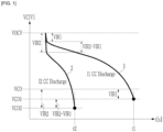
- FIG. 1 is a graph to explain a method of predicting a discharge voltage graph according to an exemplary embodiment.
- FIG. 1 shows a change of a battery cell voltage depending on a passage of a time when performing a discharge with different constant current (CC) from each other in a condition of a predetermined start SOC (State of Charge) and a predetermined start temperature.
- CC constant current
- a discharge voltage curve 1 of FIG. 1 is a graph showing the change in the battery cell voltage (VC) when being discharged with a constant current 11, and a discharge voltage curve 2 shows the change of the battery cell voltage (VC) when being discharged with a constant current I2.
- VCO may be arbitrarily selected as the discharge reference voltage when the discharge current is 0.
- VCO1, VCO2, and VCO have the relationship as shown in Equation 1.
- the discharge limit voltage means a minimum voltage at which the battery cell voltage is capable of being reduced during the discharge, and when the battery cell is discharged to a voltage that is lower than the discharge limit voltage, the battery cell may be damaged.
- the battery cell voltage VC rapidly decreases from the open circuit voltage (OCV) VOCV to the voltage drop caused by the constant current and the resistance of the battery cell, and then decreases depending on the lapse of time.
- OCV open circuit voltage
- the battery cell voltage decreases at the discharge start by the voltage drop R*I1 due to the constant current I1 and the battery cell resistance R, and the battery cell voltage decreases depending on the lapse of time, and when the time t1 elapses, the discharge limit voltage VCO1 is reached.
- the battery cell voltage decreases at the discharge start by the voltage drop R*I2 due to the constant current I2 and the battery cell resistance R, and the battery cell voltage decreases depending on the lapse of time, and when the time t2 elapses, the discharge limit voltage VCO2 is reached.
- Equation 2 "a” and “b” are the proportional constant and the index parameter between the constant current and the discharge time during the discharge.
- Equation 2 is summarized with respect to time, it is as shown in Equation 3.
- t I a 1 b
- FIG. 2 is a flowchart showing a method of determining a proportional constant and an index parameter between a constant current and a discharge time according to an exemplary embodiment.
- VCO discharge reference voltage
- FIG. 3 is a discharge voltage graph predicted when discharge occurs with a predetermined current according to an exemplary embodiment.
- FIG. 3 shows together the discharge voltage graph for each of the constant currents I1 and I2.
- OCV open circuit voltage
- VIRx R*Ix
- FIG. 4 is a graph comparing a discharge voltage test result and a prediction result for each discharge current.
- the thin solid lines 41-46 show the discharge voltage graph according to the test result
- the thick solid lines 47-50 show the predicted discharge voltage graph.
- the start SOC and start temperature are all the same SOC 60 % and 25 °C.
- C means “C-rate”
- the current corresponding to the reference capacity of the battery cell corresponds to 1 C-rate.
- 1 C means 100 A
- 2 C means 200 A.
- FIG. 5 is a graph comparing a discharge voltage test result and a prediction result for each discharge current.
- the thin solid lines 51-56 show the discharge voltage graph according to the test result
- the thick solid lines 57-60 shows the predicted discharge voltage graph.
- the start SOC and start temperature are all the same at SOC 25 % and 0 °C.
- the discharge limit current means the constant current when the battery cell voltage reaches the discharge limit voltage from the initial voltage for x seconds in the discharge voltage curve.
- the discharge resistance is calculated by dividing the value obtained by subtracting the battery cell voltage at x seconds from the initial discharge voltage of the battery cell by the discharge current.
- the discharge power may be calculated by dividing the area up to x seconds in the discharge voltage curve by x seconds.
- FIG. 6 is a view showing a battery system to which a method of predicting a discharge voltage graph according to an exemplary embodiment is applied.
- a battery system 100 includes a battery 110 including a plurality of battery cells 110_1 to 110_n connected in series, a battery management system (BMS) 111, a current sensor 112, a relay 113, and a temperature sensor 114.
- BMS battery management system
- the current sensor 112 may detect a current (hereinafter, a battery current) flowing through the battery 110 and transmitting a current detection signal SC indicating the detected battery current to the BMS 111.
- a current hereinafter, a battery current
- SC current detection signal
- the current sensor 112 is connected between a negative electrode of the battery 110 and an output terminal (P-) of the battery 110, but unlike that shown in FIG. 6 , it may be connected between the positive electrode of the battery 110 and the output terminal (P+) of the battery 110.
- the temperature sensor 114 may be positioned inside the battery 110 to measure or estimate the temperature of each of a plurality of battery cells.
- the temperature sensor 114 may transmit a signal indicating the temperature of each of a plurality of battery cells to the BMS 111.
- the BMS 111 may measure the cell voltage of a plurality of battery cells 110_1 to 110_n and measure the battery voltage that is a voltage between both terminals of the battery 110, a temperature of each of a plurality of battery cells 110_1 to 110_n, etc., and may predict the SOC of each of a plurality of battery cells 110_1 to 110_n and predict an internal resistance of each of a plurality of battery cells 110_1 to 110_n based on a plurality of battery cell voltages, the battery current, and the battery cell temperature.
- the method for estimating the SOC and the internal resistance is a known technique, and various methods may be applied to the present invention.
- the BMS 111 may control the charging and discharging based on the estimated SOC, control a balancing operation for a plurality of battery cells based on a plurality of battery cell voltages and the battery cell temperatures, and control a protection operation in a case that an overvoltage, an overcurrent, or a high temperature occur.
- the relay 114 is connected between the output terminal (P+) of the battery 110 and the positive electrode of the battery 110, and opens or closes according to the relay control signal (RCS) of the BMS 111.
- the relay 114 may be closed according to the relay control signal (RCS) of an on-level and open according to the relay control signal (RCS) of an off-level.
- the BMS 111 is possible to predict the time required to reach the discharge limit voltage (VCO_i, i is a natural number from 1 to n) corresponding to each of a plurality of battery cells 110_1 to 110_n.
- the BMS 111 may store the look-up table 115, which stores an information on the proportional constant and index parameters for each SOC and battery temperature at the start of the discharge operation.
- the BMS 111 may predict the time required to reach the discharge limit voltage (VCOx) for the corresponding battery cell voltage by using the stored proportional constant and index parameter, and Equation 3. In this case, the BMS 111 may read the proportional constant and index parameter corresponding to the same SOC and temperature as the SOC and temperature of the corresponding battery cell from the look-up table 115.
Landscapes
- Physics & Mathematics (AREA)
- General Physics & Mathematics (AREA)
- Engineering & Computer Science (AREA)
- Power Engineering (AREA)
- Manufacturing & Machinery (AREA)
- Chemical & Material Sciences (AREA)
- Chemical Kinetics & Catalysis (AREA)
- Electrochemistry (AREA)
- General Chemical & Material Sciences (AREA)
- Secondary Cells (AREA)
- Tests Of Electric Status Of Batteries (AREA)
- Charge And Discharge Circuits For Batteries Or The Like (AREA)
Abstract
Description
- This application claims priority to and the benefit of
Korean Patent Application No. 10-2021-0002661 filed in the Korean Intellectual Property Office on January 8, 2021 - The present disclosure relates to a discharge voltage graph prediction method and a battery system using the same.
- In the prior art, where there is no discharge voltage graph prediction technology for lithium ion secondary batteries, direct experiments were conducted for each discharge current to obtain a discharge voltage graph, and a discharge voltage graph of a lithium ion reachable battery for the corresponding discharge current was obtained. The discharge voltage graph is a graph of the change in the battery cell voltage depending on a passage of time when being discharged with a predetermined constant current, it is necessary to measure a discharge limit current at a predetermined time, a discharge resistance at a predetermined time, or a discharge power at a predetermined time.
- The present disclosure is to provide a discharge voltage graph prediction method that may predict the discharge voltage graph and a battery system using the same in a case of being discharged with an arbitrary constant current without information about the discharge voltage graph through experiments.
- A method for predicting a constant current discharge graph for a battery cell according to a feature of the invention includes: measuring a first time required for the battery cell voltage to decrease to a first discharge limit voltage by a first constant current discharge; measuring a second time required for the battery cell voltage to decrease to a second discharge limit voltage by a second constant current discharge; and calculating a proportional constant and an index parameter in the relationship between the constant current and the discharge time during discharging based on the first constant current and the first time, and the second constant current and the second time. The first discharge limit voltage is a voltage obtained by subtracting the first voltage drop due to the first constant current and the internal resistance of the battery cell from the discharge reference voltage when the discharge current is 0, and the second discharge limit voltage is a voltage obtained by subtracting the second voltage drop due to the second constant current and the internal resistance of the battery cell from the discharge reference voltage.
- The method of predicting the constant current discharge graph for the battery cell may further include predicting the time required for the voltage of the battery cell to reach a third discharge limit voltage by using the proportional constant and the index parameter when discharging the battery cell with the third constant current, and the third discharge limit voltage may be a voltage obtained by subtracting the third voltage drop due to the third constant current and the internal resistance of the battery cell from the discharge reference voltage.
- The method of predicting the constant current discharge graph for the battery cell may further include: changing the discharge reference voltage; measuring a third time required for the battery cell voltage to decrease to a fourth discharge limit voltage by a fourth constant current discharge; measuring a fourth time required for the battery cell voltage to decrease to a fifth discharge limit voltage by a fifth constant current discharge; and calculating the proportional constant and the index parameter in the relationship between the discharge current and the time based on the fourth constant current and the third time, and the fifth constant current and the fourth time, the fourth discharge limit voltage may be a voltage obtained by subtracting the fourth voltage drop dur to the third constant current and the internal resistance of the battery cell from the changed discharge reference voltage, and the fifth discharge limit voltage may be a voltage obtained by subtracting the fifth voltage drop due to the fourth constant current and the internal resistance of the battery cell from the changed discharge reference voltage.
- The method of predicting the constant current discharge graph for the battery cell may further include predicting the time required for the voltage of the battery cell to reach the sixth discharge limit voltage by using the proportional constant and the index parameter when discharging the battery cell with the sixth constant current, and the sixth discharge limit voltage is a voltage obtained by subtracting a sixth voltage drop due to the sixth constant current and the internal resistance of the battery cell from the changed discharge reference voltage.
- A battery system according to another feature of the invention includes: a plurality of battery cells; and a battery management system for predicting a discharge time required for each of a plurality of battery cell voltages to reach a corresponding discharge limit voltage during a constant current discharge. The battery management system may store information about a proportional constant and an index parameter defining a relationship between a constant current and a discharge time, a proportional constant and an index parameter about one among a plurality of battery cells may be calculated based a first constant current and a first time, and a second constant current and a second time after measuring a first time required for the battery cell voltage to decrease to a first discharge limit voltage by a first constant current discharge and measuring a second time required for the battery cell voltage to decrease to a second discharge limit voltage by a second constant current discharge, and the first discharge limit voltage may be a voltage obtained by subtracting the first voltage drop due to the first constant current and the internal resistance of the battery cell from the discharge reference voltage when the discharge current is 0, and the second discharge limit voltage may be a voltage obtained by subtracting the second voltage drop due to the second constant current and the internal resistance of the battery cell from the discharge reference voltage.
- The battery management system may predict the time required for the voltage of the battery cell to reach a third discharge limit voltage by using the proportional constant and the index parameter when discharging the battery cell with the third constant current, and the third discharge limit voltage may be a voltage obtained by subtracting the third voltage drop due to the third constant current and the internal resistance of the battery cell from the discharge reference voltage.
- The SOC of the battery cell and the temperature of the cell at the time of the discharge start may be the same by the first constant current, the second constant current, and the third constant current.
- The relation between the discharge current and the time may be I=a*tb, where I may be the discharge current, t may be the time, a may be the proportional constant, and b may be the index parameter.
- If discharge occurs with a constant current that has not been tested, it is difficult to predict whether the battery cell has any kind of discharge voltage graph. An exemplary embodiment of the present invention may predict the discharge voltage graph when being discharged with an arbitrary constant current.
-
-
FIG. 1 is a graph to explain a method of predicting a discharge voltage graph according to an exemplary embodiment. -
FIG. 2 is a flowchart showing a method of determining a proportional constant and an index parameter between a constant current and a discharge time according to an exemplary embodiment. -
FIG. 3 is a discharge voltage graph predicted when being discharged with a predetermined current according to an exemplary embodiment. -
FIG. 4 is a graph comparing a discharge voltage test result and a prediction result for each discharge current. -
FIG. 5 is a graph comparing a discharge voltage test result and a prediction result for each discharge current. -
FIG. 6 is a view showing a battery system to which a method of predicting a discharge voltage graph according to an exemplary embodiment is applied. - Hereinafter, embodiments disclosed in the present specification will be described in detail with reference to the accompanying drawings. In the present specification, the same or similar components will be denoted by the same or similar reference numerals, and an overlapped description thereof will be omitted. The terms "module" and "unit" for components used in the following description are used only in order to easily make a specification. Therefore, these terms do not have meanings or roles that distinguish them from each other in themselves. Further, in describing embodiments of the present specification, when it is determined that a detailed description of the well-known art associated with the present invention may obscure the gist of the present invention, it will be omitted. In addition, the accompanying drawings are provided only in order to allow embodiments disclosed in the present specification to be easily understood and are not to be interpreted as limiting the spirit disclosed in the present specification, and it is to be understood that the present invention includes all modifications, equivalents, and substitutions without departing from the scope and spirit of the present invention.
- Terms including ordinal numbers such as first, second, and the like will be used only to describe various components and are not to be interpreted as limiting these components. The terms are only used to differentiate one component from other components.
- It is to be understood that when one component is referred to as being "connected" or "coupled" to another component, it may be connected or coupled directly to another component or be connected or coupled to another component with the other component intervening therebetween. On the other hand, it is to be understood that when one component is referred to as being "connected or coupled directly" to another component, it may be connected to or coupled to another component without another component intervening therebetween.
- It will be further understood that terms "comprise" or "have" used in the present specification specify the presence of stated features, numerals, steps, operations, components, parts, or a combination thereof, but do not preclude the presence or addition of one or more other features, numerals, steps, operations, components, parts, or a combination thereof.
-
FIG. 1 is a graph to explain a method of predicting a discharge voltage graph according to an exemplary embodiment. -
FIG. 1 shows a change of a battery cell voltage depending on a passage of a time when performing a discharge with different constant current (CC) from each other in a condition of a predetermined start SOC (State of Charge) and a predetermined start temperature. - First, a
discharge voltage curve 1 ofFIG. 1 is a graph showing the change in the battery cell voltage (VC) when being discharged with aconstant current 11, and adischarge voltage curve 2 shows the change of the battery cell voltage (VC) when being discharged with a constant current I2. - In
FIG. 1 , "VCO" may be arbitrarily selected as the discharge reference voltage when the discharge current is 0. "VCO1" is the voltage (VCO-VIR1) obtained by subtracting the voltage drop (VIR1 = R*I1) from the discharge reference voltage (VCO) when the constant current I1 flows through the battery cell, and "VCO2" is the voltage (VCO-VIR2) obtained by subtracting the voltage drop (VIR2 = R*I2) from the discharge reference voltage (VCO) when the constant current I2 flows through the battery cell. That is, VCO1 is the discharge limit voltage when the discharge current is I1, and VOC2 is the discharge limit voltage when the discharge current is I2. In the condition that the start SOC and the start temperature are the same, respectively, when the CC discharge is performed, VCO1, VCO2, and VCO have the relationship as shown inEquation 1. The discharge limit voltage means a minimum voltage at which the battery cell voltage is capable of being reduced during the discharge, and when the battery cell is discharged to a voltage that is lower than the discharge limit voltage, the battery cell may be damaged.

- As shown in
FIG. 1 , when the discharge starts, the battery cell voltage VC rapidly decreases from the open circuit voltage (OCV) VOCV to the voltage drop caused by the constant current and the resistance of the battery cell, and then decreases depending on the lapse of time. The battery cell voltage decreases at the discharge start by the voltage drop R*I1 due to the constant current I1 and the battery cell resistance R, and the battery cell voltage decreases depending on the lapse of time, and when the time t1 elapses, the discharge limit voltage VCO1 is reached. The battery cell voltage decreases at the discharge start by the voltage drop R*I2 due to the constant current I2 and the battery cell resistance R, and the battery cell voltage decreases depending on the lapse of time, and when the time t2 elapses, the discharge limit voltage VCO2 is reached. - The relationship between the constant current "I" and the discharge time "t" when the battery cell is discharged satisfies
Equation 2 below.

- In
Equation 2, "a" and "b" are the proportional constant and the index parameter between the constant current and the discharge time during the discharge. - If
Equation 2 is summarized with respect to time, it is as shown inEquation 3.

-
FIG. 2 is a flowchart showing a method of determining a proportional constant and an index parameter between a constant current and a discharge time according to an exemplary embodiment. - First, two constant currents I1 and I2 are set (S0).
- Next, the discharge reference voltage VCO is selected (S1).
- When discharging with the constant current I1, the battery cell voltage VC decreases and then the time t1 required to reach the discharge limit voltage (VCO1 = VCO -R*I1) is measured (S2).
- Then, when discharging with the constant current I2, the battery cell voltage VC decreases and then the time t2 required to reach the discharge limit voltage (VCO2 = VCO -R*I2) is measured (S3).
- By substituting I1 and t1, and I2 and t2 obtained through the step (S2) and the step (S3) into
Equation 2, two simultaneous equations are obtained, and the proportional constant "a" and the index parameter "b" are obtained by solving two simultaneous equations (S4). - When the proportional constant "a" and the index parameter "b" are applied to
Equation 3, and the discharge is performed with an arbitrary constant current Ix, the time tx to reach the discharge limit voltage (VCOx) of which the voltage drop (R*lx) is subtracted from the discharge reference voltage (VCO) is calculated (S5). - The discharge reference voltage (VCO) is changed (S6) and the steps (S2 to S5) are repeated.
-
FIG. 3 is a discharge voltage graph predicted when discharge occurs with a predetermined current according to an exemplary embodiment. - To compare the times to reach the discharge limit voltage for the different constant currents I1 and I2, respectively, and the arbitrary current Ix,
FIG. 3 shows together the discharge voltage graph for each of the constant currents I1 and I2. - As shown in
FIG. 3 , in thedischarge voltage graph 3 according to an arbitrary constant current (lx), if the discharge starts, the battery cell voltage (VC) rapidly decreases from the open circuit voltage (OCV) (VOCV) by the voltage drop (VIRx = R*Ix) due to the corresponding constant current and the resistance of the battery cell, and the battery cell voltage decreases depending on the lapse of time and reaches the discharge limit voltage (VCOx) when the time tx elapses. -
FIG. 4 is a graph comparing a discharge voltage test result and a prediction result for each discharge current. - In
FIG. 4 , the thin solid lines 41-46 show the discharge voltage graph according to the test result, and the thick solid lines 47-50 show the predicted discharge voltage graph. - The start SOC and start temperature are all the same SOC 60 % and 25 °C.
- In
FIG. 4 , "C" means "C-rate", and the current corresponding to the reference capacity of the battery cell corresponds to 1 C-rate. For example, in the case of the battery cell having the reference capacity of 100 Ampere-hours (Ah), 1 C means 100 A, and 2 C means 200 A. Based on the discharge voltage graphs 42 and 45 in the discharge experiment for the constant current 3 C and 4.5 C, respectively, shown inFIG. 4 , the proportional constant "a" and index parameter "b" were calculated according to the method described above. - In
FIG. 4 , when discharging with the constant current 2.5 C, 3.5 C, 4 C, and 5 C, respectively, the result of predicting the discharge voltage has an average error of 1 mV-3 mV obtained through the actual experiment for the discharge voltage and a maximum error range of 3 mV-8 mV. That is, as shown inFIG. 4 , it may be seen that the prediction error compared to the battery cell voltage forms a significantly low value. -
FIG. 5 is a graph comparing a discharge voltage test result and a prediction result for each discharge current. - In
FIG. 5 , the thin solid lines 51-56 show the discharge voltage graph according to the test result, and the thick solid lines 57-60 shows the predicted discharge voltage graph. - The start SOC and start temperature are all the same at SOC 25 % and 0 °C.
- Based on the discharge voltage curves 53 and 55 in the discharge experiment for the constant current 2.5 C and 3.5 C, respectively, shown in
FIG. 5 , the proportional constant "a" and the index parameter "b" were calculated according to the method described above. - In
FIG. 5 , when discharging with the constant current 2.5 C, 3.5 C, 4 C, and 5 C, respectively, the results of predicting the discharge voltage have an average error of 1 mV-3 mV obtained through the actual experiment for the discharge voltage and a maximum error range of 7 mV-10 mV. That is, in the graph shown inFIG. 5 , it may be seen that the prediction error compared to the battery cell voltage forms a significantly low value. - In this way, the number of experiments for acquiring the discharge voltage graph is reduced, and the duration of the experiment is reduced. In addition, since it is possible to predict the constant current discharge voltage graph, it is possible to predict the discharge limit current for any time (x seconds elapsed from the start of the discharge), the discharge resistance for any time, or the discharge power for any time as well as the measurement. The discharge limit current means the constant current when the battery cell voltage reaches the discharge limit voltage from the initial voltage for x seconds in the discharge voltage curve. The discharge resistance is calculated by dividing the value obtained by subtracting the battery cell voltage at x seconds from the initial discharge voltage of the battery cell by the discharge current. The discharge power may be calculated by dividing the area up to x seconds in the discharge voltage curve by x seconds.
-
FIG. 6 is a view showing a battery system to which a method of predicting a discharge voltage graph according to an exemplary embodiment is applied. - As shown in
FIG. 6 , abattery system 100 includes abattery 110 including a plurality of battery cells 110_1 to 110_n connected in series, a battery management system (BMS) 111, a current sensor 112, arelay 113, and atemperature sensor 114. - The current sensor 112 may detect a current (hereinafter, a battery current) flowing through the
battery 110 and transmitting a current detection signal SC indicating the detected battery current to theBMS 111. InFIG. 6 , the current sensor 112 is connected between a negative electrode of thebattery 110 and an output terminal (P-) of thebattery 110, but unlike that shown inFIG. 6 , it may be connected between the positive electrode of thebattery 110 and the output terminal (P+) of thebattery 110. - The
temperature sensor 114 may be positioned inside thebattery 110 to measure or estimate the temperature of each of a plurality of battery cells. Thetemperature sensor 114 may transmit a signal indicating the temperature of each of a plurality of battery cells to theBMS 111. - The
BMS 111 may measure the cell voltage of a plurality of battery cells 110_1 to 110_n and measure the battery voltage that is a voltage between both terminals of thebattery 110, a temperature of each of a plurality of battery cells 110_1 to 110_n, etc., and may predict the SOC of each of a plurality of battery cells 110_1 to 110_n and predict an internal resistance of each of a plurality of battery cells 110_1 to 110_n based on a plurality of battery cell voltages, the battery current, and the battery cell temperature. The method for estimating the SOC and the internal resistance is a known technique, and various methods may be applied to the present invention. TheBMS 111 may control the charging and discharging based on the estimated SOC, control a balancing operation for a plurality of battery cells based on a plurality of battery cell voltages and the battery cell temperatures, and control a protection operation in a case that an overvoltage, an overcurrent, or a high temperature occur. - The
relay 114 is connected between the output terminal (P+) of thebattery 110 and the positive electrode of thebattery 110, and opens or closes according to the relay control signal (RCS) of theBMS 111. Therelay 114 may be closed according to the relay control signal (RCS) of an on-level and open according to the relay control signal (RCS) of an off-level. - According to the prediction method of the discharge voltage graph according to the discharge by the constant current described above, the
BMS 111 is possible to predict the time required to reach the discharge limit voltage (VCO_i, i is a natural number from 1 to n) corresponding to each of a plurality of battery cells 110_1 to 110_n. For this, theBMS 111 may store the look-up table 115, which stores an information on the proportional constant and index parameters for each SOC and battery temperature at the start of the discharge operation. - When the discharge is performed with an arbitrary constant current (Ix) for any one of a plurality of battery cells 110_1-110_n, the
BMS 111 may predict the time required to reach the discharge limit voltage (VCOx) for the corresponding battery cell voltage by using the stored proportional constant and index parameter, andEquation 3. In this case, theBMS 111 may read the proportional constant and index parameter corresponding to the same SOC and temperature as the SOC and temperature of the corresponding battery cell from the look-up table 115. - While this invention has been described in connection with what is presently considered to be practical exemplary embodiments, it is to be understood that the invention is not limited to the disclosed embodiments. On the contrary, it is intended to cover various modifications and equivalent arrangements included within the spirit and scope of the appended claims.
Claims (10)
- A method for predicting a constant current discharge graph for a battery cell, comprising:measuring a first time required for a battery cell voltage to decrease to a first discharge limit voltage by a first constant current discharge;measuring a second time required for the battery cell voltage to decrease to a second discharge limit voltage by a second constant current discharge; andcalculating a proportional constant and an index parameter in the relationship between the constant current and the discharge time during discharging based on the first constant current and the first time, and the second constant current and the second time,wherein the first discharge limit voltage is a voltage obtained by subtracting the first voltage drop due to the first constant current and the internal resistance of the battery cell from the discharge reference voltage when the discharge current is 0, and the second discharge limit voltage is a voltage obtained by subtracting the second voltage drop due to the second constant current and the internal resistance of the battery cell from the discharge reference voltage.
- The method of predicting the constant current discharge graph for the battery cell of claim 1, further comprisingpredicting the time required for the voltage of the battery cell to reach a third discharge limit voltage by using the proportional constant and the index parameter when discharging the battery cell with the third constant current, andthe third discharge limit voltage is a voltage obtained by subtracting the third voltage drop due to the third constant current and the internal resistance of the battery cell from the discharge reference voltage.
- The method of predicting the constant current discharge graph for the battery cell of claim 2, wherein
the SOC of the battery cell and the temperature of the cell at the time of the discharge start are the same by the first constant current, the second constant current, and the third constant current. - The method of predicting the constant current discharge graph for the battery cell of claim 2, further comprising:changing the discharge reference voltage;measuring a third time required for the battery cell voltage to decrease to a fourth discharge limit voltage by a fourth constant current discharge;measuring a fourth time required for the battery cell voltage to decrease to a fifth discharge limit voltage by a fifth constant current discharge; andcalculating the proportional constant and the index parameter in the relationship between the discharge current and the time based on the fourth constant current and the third time, and the fifth constant current and the fourth time, whereinthe fourth discharge limit voltage is a voltage obtained by subtracting the fourth voltage drop due to the third constant current and the internal resistance of the battery cell from the changed discharge reference voltage, and the fifth discharge limit voltage is a voltage obtained by subtracting the fifth voltage drop due to the fourth constant current and the internal resistance of the battery cell from the changed discharge reference voltage.
- The method of predicting the constant current discharge graph for the battery cell of claim 4, further comprisingpredicting the time required for the voltage of the battery cell to reach the sixth discharge limit voltage by using the proportional constant and the index parameter when discharging the battery cell with the sixth constant current, andthe sixth discharge limit voltage is a voltage obtained by subtracting a sixth voltage drop due to the sixth constant current and the internal resistance of the battery cell from the changed discharge reference voltage.
- The method of predicting the constant current discharge graph for the battery cell of claim 1, whereinthe relation between the discharge current and the time is the same as shown in Equation 1,
 wherein, in Equation 1, I is the discharge current, t is the time, a is the proportional constant, and b is the index parameter.
 - A battery system comprising:a plurality of battery cells; anda battery management system for predicting a discharge time required for each of a plurality of battery cell voltages to reach a corresponding discharge limit voltage during a constant current discharge,wherein the battery management system stores information about a proportional constant and an index parameter defining a relationship between a constant current and a discharge time,the proportional constant and the index parameter about one among a plurality of battery cells are calculated based a first constant current and a first time, and a second constant current and a second time after measuring the first time required for the battery cell voltage to decrease to a first discharge limit voltage by a first constant current discharge and measuring the second time required for the battery cell voltage to decrease to a second discharge limit voltage by a second constant current discharge,the first discharge limit voltage is a voltage obtained by subtracting the first voltage drop due to the first constant current and the internal resistance of the battery cell from the discharge reference voltage when the discharge current is 0, and the second discharge limit voltage is a voltage obtained by subtracting the second voltage drop due to the second constant current and the internal resistance of the battery cell from the discharge reference voltage.
- The battery system of claim 7, whereinthe battery management system predicts the time required for the voltage of the battery cell to reach a third discharge limit voltage by using the proportional constant and the index parameter when discharging the battery cell with the third constant current, andthe third discharge limit voltage is a voltage obtained by subtracting the third voltage drop due to the third constant current and the internal resistance of the battery cell from the discharge reference voltage.
- The battery system of claim 8, wherein
the SOC of the battery cell and the temperature of the cell at the time of the discharge start are the same by the first constant current, the second constant current, and the third constant current. - The battery system of claim 7, whereinthe relation between the discharge current and the time is the same as shown in Equation 1,
 wherein, in Equation 1, I is the discharge current, t is the time, a is the proportional constant, and b is the index parameter.
Applications Claiming Priority (2)
| Application Number | Priority Date | Filing Date | Title |
|---|---|---|---|
| KR1020210002661A KR102892944B1 (en) | 2021-01-08 | 2021-01-08 | Discharge voltage graph prediction method and battery system using same |
| PCT/KR2021/019714 WO2022149770A1 (en) | 2021-01-08 | 2021-12-23 | Discharge voltage graph prediction method and battery system using same |
Publications (3)
| Publication Number | Publication Date |
|---|---|
| EP4194868A1 true EP4194868A1 (en) | 2023-06-14 |
| EP4194868A4 EP4194868A4 (en) | 2024-04-10 |
| EP4194868B1 EP4194868B1 (en) | 2025-10-15 |
Family
ID=82357197
Family Applications (1)
| Application Number | Title | Priority Date | Filing Date |
|---|---|---|---|
| EP21917932.2A Active EP4194868B1 (en) | 2021-01-08 | 2021-12-23 | Discharge voltage graph prediction method and battery system using the same |
Country Status (7)
| Country | Link |
|---|---|
| US (1) | US20230314516A1 (en) |
| EP (1) | EP4194868B1 (en) |
| JP (1) | JP7468939B2 (en) |
| KR (1) | KR102892944B1 (en) |
| CN (1) | CN116324443B (en) |
| ES (1) | ES3051507T3 (en) |
| WO (1) | WO2022149770A1 (en) |
Families Citing this family (3)
| Publication number | Priority date | Publication date | Assignee | Title |
|---|---|---|---|---|
| CN112311038B (en) * | 2019-07-31 | 2023-04-18 | 荣耀终端有限公司 | Charging and discharging protection circuit, terminal equipment and battery discharging control method |
| JP7484870B2 (en) * | 2021-11-01 | 2024-05-16 | トヨタ自動車株式会社 | Battery pack deterioration diagnostic device and battery pack deterioration diagnostic method |
| US12488850B2 (en) * | 2023-03-23 | 2025-12-02 | SanDisk Technologies, Inc. | Capacitor health check for data storage devices |
Family Cites Families (23)
| Publication number | Priority date | Publication date | Assignee | Title |
|---|---|---|---|---|
| EP0637754B1 (en) * | 1993-01-27 | 2002-09-25 | Seiko Epson Corporation | Battery capacity meter |
| JP3379283B2 (en) * | 1994-07-04 | 2003-02-24 | 株式会社日本自動車部品総合研究所 | Battery state of charge detection method |
| JPH08136626A (en) * | 1994-09-16 | 1996-05-31 | Seiko Epson Corp | Battery remaining capacity meter and method for calculating battery remaining capacity |
| KR960015561B1 (en) * | 1994-09-27 | 1996-11-18 | 삼성전자 주식회사 | Battery remaining capacity measurement method using multistage Pukeker's equation |
| US5574353A (en) * | 1995-03-31 | 1996-11-12 | Motorola, Inc. | Electrochemical charge storage device having constant voltage discharge |
| US6411911B1 (en) * | 1999-06-30 | 2002-06-25 | Tyco Electronics Logistics Ag | Battery diagnostic method utilizing a universal normalized discharge curve for predicting battery reserve time |
| EP1167987B1 (en) * | 1999-10-08 | 2005-06-15 | Yazaki Corporation | Battery capacity calculating method and device therefor |
| US6529840B1 (en) * | 1999-10-26 | 2003-03-04 | Cellon France | Device for estimating the state of charge of a battery |
| CN1639894A (en) | 2002-02-15 | 2005-07-13 | 永备电池有限公司 | Cylindrical alkaline cells with increased discharge performance |
| JP4030331B2 (en) * | 2002-03-28 | 2008-01-09 | 日本碍子株式会社 | Control device for sodium-sulfur battery |
| JP4647509B2 (en) | 2005-03-04 | 2011-03-09 | 株式会社オートネットワーク技術研究所 | Battery state management device and management method |
| JP5031231B2 (en) | 2005-12-09 | 2012-09-19 | 株式会社Nttファシリティーズ | Discharge time calculation device and discharge time calculation method |
| KR101134894B1 (en) * | 2006-06-28 | 2012-04-13 | 엘지전자 주식회사 | Apparatus and method for detecting and displaying the remains of battery capacity |
| JP4956476B2 (en) | 2008-03-31 | 2012-06-20 | 古河電気工業株式会社 | Battery discharge duration prediction method, battery state detection method, battery state detection device, and battery power supply system |
| TWI431835B (en) | 2011-09-08 | 2014-03-21 | 亞旭電子科技(江蘇)有限公司 | Battery charge and discharge management system and method |
| JP2014099972A (en) * | 2012-11-13 | 2014-05-29 | Yamaha Motor Co Ltd | Method and apparatus for controlling discharge of secondary battery |
| JP2013253991A (en) | 2012-11-30 | 2013-12-19 | Gs Yuasa Corp | Deteriorated capacity estimating device and deteriorated capacity estimating method for electricity storage elements, and electricity storage system |
| CN104535932B (en) * | 2014-12-20 | 2017-04-19 | 吉林大学 | Lithium ion battery charge state estimating method |
| CN107431367B (en) * | 2015-03-02 | 2020-08-11 | 日本汽车能源株式会社 | Battery control device and vehicle system |
| JP6789299B2 (en) | 2016-01-13 | 2020-11-25 | フレックストロニックス エーピー エルエルシー | Method of estimating discharge duration during high rate battery discharge |
| JP7106362B2 (en) | 2018-06-15 | 2022-07-26 | 大和製罐株式会社 | Storage battery charge/discharge curve estimation device and charge/discharge curve estimation method |
| CN110618389A (en) * | 2019-09-25 | 2019-12-27 | 宝能汽车有限公司 | Method and device for testing battery SOC-OCV curve |
| CN111487534A (en) * | 2020-04-20 | 2020-08-04 | 芜湖职业技术学院 | Method for predicting residual discharge time of storage battery |
-
2021
- 2021-01-08 KR KR1020210002661A patent/KR102892944B1/en active Active
- 2021-12-23 EP EP21917932.2A patent/EP4194868B1/en active Active
- 2021-12-23 ES ES21917932T patent/ES3051507T3/en active Active
- 2021-12-23 JP JP2022578972A patent/JP7468939B2/en active Active
- 2021-12-23 CN CN202180063859.5A patent/CN116324443B/en active Active
- 2021-12-23 US US18/025,110 patent/US20230314516A1/en active Pending
- 2021-12-23 WO PCT/KR2021/019714 patent/WO2022149770A1/en not_active Ceased
Also Published As
| Publication number | Publication date |
|---|---|
| WO2022149770A1 (en) | 2022-07-14 |
| EP4194868B1 (en) | 2025-10-15 |
| CN116324443A (en) | 2023-06-23 |
| JP2023531680A (en) | 2023-07-25 |
| JP7468939B2 (en) | 2024-04-16 |
| US20230314516A1 (en) | 2023-10-05 |
| KR20220100330A (en) | 2022-07-15 |
| ES3051507T3 (en) | 2025-12-29 |
| CN116324443B (en) | 2025-10-28 |
| EP4194868A4 (en) | 2024-04-10 |
| KR102892944B1 (en) | 2025-11-27 |
Similar Documents
| Publication | Publication Date | Title |
|---|---|---|
| EP4198537B1 (en) | Battery soh estimating apparatus and method | |
| EP3961233B1 (en) | Battery cell diagnosis device and method | |
| EP2700966B1 (en) | Apparatus and method for estimating battery state | |
| EP4024066B1 (en) | Apparatus and method for diagnosing a battery | |
| EP4155746A1 (en) | Battery diagnostic device and method | |
| EP3410137B1 (en) | Cell state estimation device, cell control device, cell system, and cell state estimation method | |
| EP3842816B1 (en) | Soh estimation method of battery pack | |
| EP4194868A1 (en) | Discharge voltage graph prediction method and battery system using same | |
| US10024924B2 (en) | Remaining battery life prediction device and battery pack | |
| EP4212896A1 (en) | Method for estimating state of charge of battery | |
| EP4148442B1 (en) | Maximum discharge current prediction method and battery system using the same | |
| EP3605123B1 (en) | Storage battery control device and control method | |
| EP3992649B1 (en) | Battery parameter setting apparatus and method | |
| EP3901643B1 (en) | Apparatus and method for determining abnormality of a battery cell | |
| Lee et al. | Maximum pulse current estimation for high accuracy power capability prediction of a Li-Ion battery | |
| EP3748388B1 (en) | Apparatus and method for diagnosing current sensor | |
| EP4083641B1 (en) | Semiconductor device for monitoring battery remaining capacity | |
| Ajao et al. | Dynamic cell modeling of Li-Ion polymer batteries for precise SOC estimation in power-needy autonomous electric vehicles | |
| EP4592696A1 (en) | Battery state of health (soh) estimating method and battery system providing same | |
| Miftahullatif et al. | Novel state-of-health prediction method for lithium-ion batteries in battery storage system by using voltage variation at rest period after discharge | |
| Balasingam et al. | Battery fuel gauge: A crucial element in battery management systems | |
| US20240361388A1 (en) | Cell voltage estimation method and battery system providing the same | |
| EP4318005A1 (en) | Apparatus and method for estimating state of battery | |
| EP4617689A1 (en) | Battery state estimation method and battery system providing same |
Legal Events
| Date | Code | Title | Description |
|---|---|---|---|
| STAA | Information on the status of an ep patent application or granted ep patent |
Free format text: STATUS: THE INTERNATIONAL PUBLICATION HAS BEEN MADE |
|
| PUAI | Public reference made under article 153(3) epc to a published international application that has entered the european phase |
Free format text: ORIGINAL CODE: 0009012 |
|
| STAA | Information on the status of an ep patent application or granted ep patent |
Free format text: STATUS: REQUEST FOR EXAMINATION WAS MADE |
|
| 17P | Request for examination filed |
Effective date: 20230309 |
|
| AK | Designated contracting states |
Kind code of ref document: A1 Designated state(s): AL AT BE BG CH CY CZ DE DK EE ES FI FR GB GR HR HU IE IS IT LI LT LU LV MC MK MT NL NO PL PT RO RS SE SI SK SM TR |
|
| A4 | Supplementary search report drawn up and despatched |
Effective date: 20240312 |
|
| RIC1 | Information provided on ipc code assigned before grant |
Ipc: H01M 10/42 20060101ALI20240305BHEP Ipc: H01M 10/48 20060101ALI20240305BHEP Ipc: G01R 31/396 20190101ALI20240305BHEP Ipc: G01R 31/385 20190101ALI20240305BHEP Ipc: G01R 19/175 20060101ALI20240305BHEP Ipc: G01R 19/10 20060101ALI20240305BHEP Ipc: G01R 31/382 20190101ALI20240305BHEP Ipc: G01R 31/36 20200101ALI20240305BHEP Ipc: G01R 31/367 20190101AFI20240305BHEP |
|
| DAV | Request for validation of the european patent (deleted) | ||
| DAX | Request for extension of the european patent (deleted) | ||
| GRAP | Despatch of communication of intention to grant a patent |
Free format text: ORIGINAL CODE: EPIDOSNIGR1 |
|
| STAA | Information on the status of an ep patent application or granted ep patent |
Free format text: STATUS: GRANT OF PATENT IS INTENDED |
|
| INTG | Intention to grant announced |
Effective date: 20250507 |
|
| RIC1 | Information provided on ipc code assigned before grant |
Ipc: H02J 7/00 20060101ALI20250426BHEP Ipc: H01M 10/42 20060101ALI20250426BHEP Ipc: H01M 10/48 20060101ALI20250426BHEP Ipc: G01R 31/396 20190101ALI20250426BHEP Ipc: G01R 31/385 20190101ALI20250426BHEP Ipc: G01R 19/175 20060101ALI20250426BHEP Ipc: G01R 19/10 20060101ALI20250426BHEP Ipc: G01R 31/382 20190101ALI20250426BHEP Ipc: G01R 31/36 20200101ALI20250426BHEP Ipc: G01R 31/367 20190101AFI20250426BHEP |
|
| P01 | Opt-out of the competence of the unified patent court (upc) registered |
Free format text: CASE NUMBER: APP_26057/2025 Effective date: 20250602 |
|
| GRAS | Grant fee paid |
Free format text: ORIGINAL CODE: EPIDOSNIGR3 |
|
| GRAA | (expected) grant |
Free format text: ORIGINAL CODE: 0009210 |
|
| STAA | Information on the status of an ep patent application or granted ep patent |
Free format text: STATUS: THE PATENT HAS BEEN GRANTED |
|
| AK | Designated contracting states |
Kind code of ref document: B1 Designated state(s): AL AT BE BG CH CY CZ DE DK EE ES FI FR GB GR HR HU IE IS IT LI LT LU LV MC MK MT NL NO PL PT RO RS SE SI SK SM TR |
|
| REG | Reference to a national code |
Ref country code: GB Ref legal event code: FG4D Ref country code: CH Ref legal event code: F10 Free format text: ST27 STATUS EVENT CODE: U-0-0-F10-F00 (AS PROVIDED BY THE NATIONAL OFFICE) Effective date: 20251015 |
|
| REG | Reference to a national code |
Ref country code: DE Ref legal event code: R096 Ref document number: 602021040649 Country of ref document: DE |
|
| REG | Reference to a national code |
Ref country code: IE Ref legal event code: FG4D |
|
| REG | Reference to a national code |
Ref country code: ES Ref legal event code: FG2A Ref document number: 3051507 Country of ref document: ES Kind code of ref document: T3 Effective date: 20251229 |
|
| PGFP | Annual fee paid to national office [announced via postgrant information from national office to epo] |
Ref country code: GB Payment date: 20251222 Year of fee payment: 5 |
|
| PGFP | Annual fee paid to national office [announced via postgrant information from national office to epo] |
Ref country code: AT Payment date: 20260113 Year of fee payment: 5 |
|
| PGFP | Annual fee paid to national office [announced via postgrant information from national office to epo] |
Ref country code: FR Payment date: 20251223 Year of fee payment: 5 |
|
| PGFP | Annual fee paid to national office [announced via postgrant information from national office to epo] |
Ref country code: BE Payment date: 20251229 Year of fee payment: 5 |
|
| REG | Reference to a national code |
Ref country code: NL Ref legal event code: MP Effective date: 20251015 |
|
| PGFP | Annual fee paid to national office [announced via postgrant information from national office to epo] |
Ref country code: HU Payment date: 20260129 Year of fee payment: 5 |
|
| REG | Reference to a national code |
Ref country code: AT Ref legal event code: MK05 Ref document number: 1847369 Country of ref document: AT Kind code of ref document: T Effective date: 20251015 |
|
| PG25 | Lapsed in a contracting state [announced via postgrant information from national office to epo] |
Ref country code: NL Free format text: LAPSE BECAUSE OF FAILURE TO SUBMIT A TRANSLATION OF THE DESCRIPTION OR TO PAY THE FEE WITHIN THE PRESCRIBED TIME-LIMIT Effective date: 20251015 |
|
| PGFP | Annual fee paid to national office [announced via postgrant information from national office to epo] |
Ref country code: ES Payment date: 20260122 Year of fee payment: 5 |
|
| REG | Reference to a national code |
Ref country code: LT Ref legal event code: MG9D |
|
| PG25 | Lapsed in a contracting state [announced via postgrant information from national office to epo] |
Ref country code: NO Free format text: LAPSE BECAUSE OF FAILURE TO SUBMIT A TRANSLATION OF THE DESCRIPTION OR TO PAY THE FEE WITHIN THE PRESCRIBED TIME-LIMIT Effective date: 20260115 |
|
| PGFP | Annual fee paid to national office [announced via postgrant information from national office to epo] |
Ref country code: DE Payment date: 20251222 Year of fee payment: 5 |
|
| PG25 | Lapsed in a contracting state [announced via postgrant information from national office to epo] |
Ref country code: HR Free format text: LAPSE BECAUSE OF FAILURE TO SUBMIT A TRANSLATION OF THE DESCRIPTION OR TO PAY THE FEE WITHIN THE PRESCRIBED TIME-LIMIT Effective date: 20251015 Ref country code: FI Free format text: LAPSE BECAUSE OF FAILURE TO SUBMIT A TRANSLATION OF THE DESCRIPTION OR TO PAY THE FEE WITHIN THE PRESCRIBED TIME-LIMIT Effective date: 20251015 Ref country code: AT Free format text: LAPSE BECAUSE OF FAILURE TO SUBMIT A TRANSLATION OF THE DESCRIPTION OR TO PAY THE FEE WITHIN THE PRESCRIBED TIME-LIMIT Effective date: 20251015 |
|
| PG25 | Lapsed in a contracting state [announced via postgrant information from national office to epo] |
Ref country code: RS Free format text: LAPSE BECAUSE OF FAILURE TO SUBMIT A TRANSLATION OF THE DESCRIPTION OR TO PAY THE FEE WITHIN THE PRESCRIBED TIME-LIMIT Effective date: 20260115 |
|
| PG25 | Lapsed in a contracting state [announced via postgrant information from national office to epo] |
Ref country code: IS Free format text: LAPSE BECAUSE OF FAILURE TO SUBMIT A TRANSLATION OF THE DESCRIPTION OR TO PAY THE FEE WITHIN THE PRESCRIBED TIME-LIMIT Effective date: 20260215 |
|
| PG25 | Lapsed in a contracting state [announced via postgrant information from national office to epo] |
Ref country code: PT Free format text: LAPSE BECAUSE OF FAILURE TO SUBMIT A TRANSLATION OF THE DESCRIPTION OR TO PAY THE FEE WITHIN THE PRESCRIBED TIME-LIMIT Effective date: 20260216 |
|
| PG25 | Lapsed in a contracting state [announced via postgrant information from national office to epo] |
Ref country code: PL Free format text: LAPSE BECAUSE OF FAILURE TO SUBMIT A TRANSLATION OF THE DESCRIPTION OR TO PAY THE FEE WITHIN THE PRESCRIBED TIME-LIMIT Effective date: 20251015 |
|
| PG25 | Lapsed in a contracting state [announced via postgrant information from national office to epo] |
Ref country code: LV Free format text: LAPSE BECAUSE OF FAILURE TO SUBMIT A TRANSLATION OF THE DESCRIPTION OR TO PAY THE FEE WITHIN THE PRESCRIBED TIME-LIMIT Effective date: 20251015 |