EP4194818A2 - Anti-vibration bracket for subsea equipment - Google Patents
Anti-vibration bracket for subsea equipment Download PDFInfo
- Publication number
- EP4194818A2 EP4194818A2 EP22195460.5A EP22195460A EP4194818A2 EP 4194818 A2 EP4194818 A2 EP 4194818A2 EP 22195460 A EP22195460 A EP 22195460A EP 4194818 A2 EP4194818 A2 EP 4194818A2
- Authority
- EP
- European Patent Office
- Prior art keywords
- slots
- component
- array
- vibration bracket
- subsea equipment
- Prior art date
- Legal status (The legal status is an assumption and is not a legal conclusion. Google has not performed a legal analysis and makes no representation as to the accuracy of the status listed.)
- Granted
Links
Images


Classifications
-
- G—PHYSICS
- G01—MEASURING; TESTING
- G01F—MEASURING VOLUME, VOLUME FLOW, MASS FLOW OR LIQUID LEVEL; METERING BY VOLUME
- G01F1/00—Measuring the volume flow or mass flow of fluid or fluent solid material wherein the fluid passes through a meter in a continuous flow
- G01F1/05—Measuring the volume flow or mass flow of fluid or fluent solid material wherein the fluid passes through a meter in a continuous flow by using mechanical effects
- G01F1/34—Measuring the volume flow or mass flow of fluid or fluent solid material wherein the fluid passes through a meter in a continuous flow by using mechanical effects by measuring pressure or differential pressure
- G01F1/36—Measuring the volume flow or mass flow of fluid or fluent solid material wherein the fluid passes through a meter in a continuous flow by using mechanical effects by measuring pressure or differential pressure the pressure or differential pressure being created by the use of flow constriction
- G01F1/363—Measuring the volume flow or mass flow of fluid or fluent solid material wherein the fluid passes through a meter in a continuous flow by using mechanical effects by measuring pressure or differential pressure the pressure or differential pressure being created by the use of flow constriction with electrical or electro-mechanical indication
-
- F—MECHANICAL ENGINEERING; LIGHTING; HEATING; WEAPONS; BLASTING
- F16—ENGINEERING ELEMENTS AND UNITS; GENERAL MEASURES FOR PRODUCING AND MAINTAINING EFFECTIVE FUNCTIONING OF MACHINES OR INSTALLATIONS; THERMAL INSULATION IN GENERAL
- F16M—FRAMES, CASINGS OR BEDS OF ENGINES, MACHINES OR APPARATUS, NOT SPECIFIC TO ENGINES, MACHINES OR APPARATUS PROVIDED FOR ELSEWHERE; STANDS; SUPPORTS
- F16M13/00—Other supports for positioning apparatus or articles; Means for steadying hand-held apparatus or articles
- F16M13/02—Other supports for positioning apparatus or articles; Means for steadying hand-held apparatus or articles for supporting on, or attaching to, an object, e.g. tree, gate, window-frame, cycle
-
- F—MECHANICAL ENGINEERING; LIGHTING; HEATING; WEAPONS; BLASTING
- F16—ENGINEERING ELEMENTS AND UNITS; GENERAL MEASURES FOR PRODUCING AND MAINTAINING EFFECTIVE FUNCTIONING OF MACHINES OR INSTALLATIONS; THERMAL INSULATION IN GENERAL
- F16F—SPRINGS; SHOCK-ABSORBERS; MEANS FOR DAMPING VIBRATION
- F16F1/00—Springs
- F16F1/36—Springs made of rubber or other material having high internal friction, e.g. thermoplastic elastomers
- F16F1/38—Springs made of rubber or other material having high internal friction, e.g. thermoplastic elastomers with a sleeve of elastic material between a rigid outer sleeve and a rigid inner sleeve or pin, i.e. bushing-type
- F16F1/3842—Method of assembly, production or treatment; Mounting thereof
- F16F1/3849—Mounting brackets therefor, e.g. stamped steel brackets; Restraining links
-
- F—MECHANICAL ENGINEERING; LIGHTING; HEATING; WEAPONS; BLASTING
- F16—ENGINEERING ELEMENTS AND UNITS; GENERAL MEASURES FOR PRODUCING AND MAINTAINING EFFECTIVE FUNCTIONING OF MACHINES OR INSTALLATIONS; THERMAL INSULATION IN GENERAL
- F16F—SPRINGS; SHOCK-ABSORBERS; MEANS FOR DAMPING VIBRATION
- F16F15/00—Suppression of vibrations in systems; Means or arrangements for avoiding or reducing out-of-balance forces, e.g. due to motion
- F16F15/02—Suppression of vibrations of non-rotating, e.g. reciprocating systems; Suppression of vibrations of rotating systems by use of members not moving with the rotating systems
- F16F15/04—Suppression of vibrations of non-rotating, e.g. reciprocating systems; Suppression of vibrations of rotating systems by use of members not moving with the rotating systems using elastic means
- F16F15/06—Suppression of vibrations of non-rotating, e.g. reciprocating systems; Suppression of vibrations of rotating systems by use of members not moving with the rotating systems using elastic means with metal springs
-
- F—MECHANICAL ENGINEERING; LIGHTING; HEATING; WEAPONS; BLASTING
- F16—ENGINEERING ELEMENTS AND UNITS; GENERAL MEASURES FOR PRODUCING AND MAINTAINING EFFECTIVE FUNCTIONING OF MACHINES OR INSTALLATIONS; THERMAL INSULATION IN GENERAL
- F16F—SPRINGS; SHOCK-ABSORBERS; MEANS FOR DAMPING VIBRATION
- F16F7/00—Vibration-dampers; Shock-absorbers
-
- F—MECHANICAL ENGINEERING; LIGHTING; HEATING; WEAPONS; BLASTING
- F16—ENGINEERING ELEMENTS AND UNITS; GENERAL MEASURES FOR PRODUCING AND MAINTAINING EFFECTIVE FUNCTIONING OF MACHINES OR INSTALLATIONS; THERMAL INSULATION IN GENERAL
- F16L—PIPES; JOINTS OR FITTINGS FOR PIPES; SUPPORTS FOR PIPES, CABLES OR PROTECTIVE TUBING; MEANS FOR THERMAL INSULATION IN GENERAL
- F16L1/00—Laying or reclaiming pipes; Repairing or joining pipes on or under water
- F16L1/12—Laying or reclaiming pipes on or under water
- F16L1/123—Devices for the protection of pipes under water
-
- G—PHYSICS
- G01—MEASURING; TESTING
- G01F—MEASURING VOLUME, VOLUME FLOW, MASS FLOW OR LIQUID LEVEL; METERING BY VOLUME
- G01F1/00—Measuring the volume flow or mass flow of fluid or fluent solid material wherein the fluid passes through a meter in a continuous flow
- G01F1/05—Measuring the volume flow or mass flow of fluid or fluent solid material wherein the fluid passes through a meter in a continuous flow by using mechanical effects
- G01F1/34—Measuring the volume flow or mass flow of fluid or fluent solid material wherein the fluid passes through a meter in a continuous flow by using mechanical effects by measuring pressure or differential pressure
- G01F1/36—Measuring the volume flow or mass flow of fluid or fluent solid material wherein the fluid passes through a meter in a continuous flow by using mechanical effects by measuring pressure or differential pressure the pressure or differential pressure being created by the use of flow constriction
- G01F1/40—Details of construction of the flow constriction devices
- G01F1/44—Venturi tubes
-
- G—PHYSICS
- G01—MEASURING; TESTING
- G01F—MEASURING VOLUME, VOLUME FLOW, MASS FLOW OR LIQUID LEVEL; METERING BY VOLUME
- G01F15/00—Details of, or accessories for, apparatus of groups G01F1/00 - G01F13/00 insofar as such details or appliances are not adapted to particular types of such apparatus
- G01F15/18—Supports or connecting means for meters
-
- F—MECHANICAL ENGINEERING; LIGHTING; HEATING; WEAPONS; BLASTING
- F16—ENGINEERING ELEMENTS AND UNITS; GENERAL MEASURES FOR PRODUCING AND MAINTAINING EFFECTIVE FUNCTIONING OF MACHINES OR INSTALLATIONS; THERMAL INSULATION IN GENERAL
- F16F—SPRINGS; SHOCK-ABSORBERS; MEANS FOR DAMPING VIBRATION
- F16F2228/00—Functional characteristics, e.g. variability, frequency-dependence
- F16F2228/06—Stiffness
-
- F—MECHANICAL ENGINEERING; LIGHTING; HEATING; WEAPONS; BLASTING
- F16—ENGINEERING ELEMENTS AND UNITS; GENERAL MEASURES FOR PRODUCING AND MAINTAINING EFFECTIVE FUNCTIONING OF MACHINES OR INSTALLATIONS; THERMAL INSULATION IN GENERAL
- F16F—SPRINGS; SHOCK-ABSORBERS; MEANS FOR DAMPING VIBRATION
- F16F2230/00—Purpose; Design features
- F16F2230/36—Holes, slots or the like
-
- F—MECHANICAL ENGINEERING; LIGHTING; HEATING; WEAPONS; BLASTING
- F16—ENGINEERING ELEMENTS AND UNITS; GENERAL MEASURES FOR PRODUCING AND MAINTAINING EFFECTIVE FUNCTIONING OF MACHINES OR INSTALLATIONS; THERMAL INSULATION IN GENERAL
- F16F—SPRINGS; SHOCK-ABSORBERS; MEANS FOR DAMPING VIBRATION
- F16F2234/00—Shape
- F16F2234/06—Shape plane or flat
Definitions
- the present invention relates to an anti-vibration bracket, in particular, but not exclusively, used for mounting components in subsea environments.
- Vibrations can damage both electronics and mechanical components over time and decrease their service life or even cause failure of the equipment. Vibrations can cause bolts to fail, and welds can suffer fatigue while exposed to vibrations over time.
- Known elastomeric vibration dampeners are not suitable for subsea applications because the elastomer dissolves in seawater over time.
- an object of the present invention is to dampen vibrations emanating from a component to another component mounted thereto.
- a subsea equipment assembly comprising a first component having an axis, a second component and an anti-vibration bracket.
- the anti-vibration bracket is attached to the first component and the second component.
- the first component is caused to vibrate at least in a radial direction relative to the axis.
- the anti-vibration bracket comprises a plate portion.
- the plate portion extends at least radially away from the first component and comprises an attachment region located a radial distance away from the first component.
- the second component is attached to the attachment region.
- the anti-vibration bracket comprises an array of slots. At least some of the slots of the array of slots are located between the first component and the attachment region.
- At least some of the slots of the array of slots may be located radially outwardly of the attachment region.
- At least some of the slots of the array of slots may be located to a lateral side of the attachment region.
- At least some of the slots of the array of slots may be arranged in at least one row with respect to the radial direction.
- At least some of the slots of the array of slots may be arranged in at least two rows with respect to the radial direction.
- the array of slots may be arranged such that any radial line passes through at least one of the slots and either a contact point between the anti-vibration bracket and the first component or where the anti-vibration bracket is attached to the first component.
- At least some of the slots of the array of slots may be arranged such that their centreline is at an angle to a radial line.
- the angle may be between -45° and +45°, preferably between -15° and +15°.
- At least some of the slots of the array of slots may be curved.
- at least some of the slots of the array of slots may have a curvature with a constant radius and preferably a radius from the axis.
- the anti-vibration bracket may comprise an edge region and none of the slots the array of slots are within the edge region.
- At least some of slots of the array of slots may extend through the anti-vibration bracket.
- At least some of slots of the array of slots may extend partly through the anti-vibration bracket.
- the first component may be a venturi flow meter and the second component may be a differential pressure sensor.
- At least some of the slots of the array of slots may have an aspect ratio between and including 2 and 20.
- a radial line from the axis may pass through the slots.
- the slots may be located between the first component and the attachment region.
- FIG 1 and Figure 2 are opposing views on a subsea equipment assembly 10 comprising a first component 12, in this example a venturi flow meter 12, and a second component 14, in this example a differential pressure sensor 14.
- the differential pressure sensor 14 is mounted to the venturi flow meter 12 via an anti-vibration bracket 16 and in accordance with the present invention.
- two differential pressure sensors 14 are present.
- Two differential transducers 14 are provided for redundancy purposes.
- the venturi flow meter 12 is located along a pipeline (not shown) and which would be bolted to end flanges 20, 22.
- the venturi flow meter 12 has an axis 18 along which a fluid flows in use.
- the direction of the flow of fluid in the pipeline and passing through the venturi flow meter 12 is from left (upstream) to right (downstream) as shown by the arrow 26.
- the differential pressure sensor 14 is capable of measuring parameters of the fluid flowing through the venturi flow meter 12 such as flow rate and pressure within the fluid. Specifically, the differential pressure sensor 14 is measuring the differential pressure in the fluid between an inlet diameter and a restriction in the venturi flow meter 12 as known in the art.
- the fluid passing through the pipeline and venturi flow meter 12 may comprise different fluids such as sea water and oil as well as solids such as sands and gravels.
- the different densities of the fluid and solids cause eccentric forces as the fluid is accelerated and decelerated through the venturi and which generates the vibrations.
- the vibrations manifest in the radial or Y-direction and axial (18) or X-direction.
- a reference axis is shown with X denoting the direction of the axis 18, Y is the radial direction and Z is a direction perpendicular to X and Z.
- An axial plane is defined by a plane that is perpendicular to the X direction or the axis 18.
- the differential pressure sensor 14 is bolted to the anti-vibration bracket 16 via an array of bolts 24.
- the anti-vibration bracket 16 is bolted to the venturi flow meter 12 and extends radially and in an axial plane with respect to the axis 18.
- the anti-vibration bracket 16 is located at an upstream part of the venturi flow meter 12.
- At a downstream part of the venturi flow meter 12 is located a pair of brackets 30, 32.
- the brackets 30, 32 are bolted to the venturi flow meter 12 and extend radially and in an axial plane relative to the axis 18.
- a guard plate 34, 36 is mounted to each one of the brackets 30, 32 respectively and to the anti-vibration bracket 16.
- the guard plates 34, 36 protect the subsea equipment assembly 10 from damage such as from drag lines or fishing nets.
- a radially outer part 38 of the guard plates 34, 36 and a radially outer part 40 of the anti-vibration bracket 16 are curved such that objects that might otherwise snag are deflected harmlessly over the subsea equipment assembly 10.
- the anti-vibration bracket 16 may be located at a downstream part of the venturi flow meter 12 and the pair of brackets 30, 32 are located at an upstream part of the venturi flow meter 12.
- FIGS. 3 and Figure 4 are views on different embodiments of the anti-vibration bracket 16 and which are in accordance with the present invention.
- like features are denoted by the same reference numbers.
- fluid passing through the venturi flow meter 12 causes vibrations. Previously, these vibrations can cause damage to components such as the differential pressure sensor 14, welds and bolts of the subsea equipment assembly 10.
- the present anti-vibration bracket 16 is generally plate-like in form and has a plate portion 52 having a thickness.
- the anti-vibration bracket 16 is metallic and preferably a stainless steel, but other metals and alloys may be used and particularly those that are resistant to corrosion in harsh environments such as sea water.
- the anti-vibration bracket 16 comprises an edge 28 which is a complementary shape to the outer surface 42 (see Figure 2 ) of the venturi flow meter 12.
- the edge 28 is the radially innermost part of the anti-vibration bracket 16 when assembled to the subsea equipment assembly 10.
- the plate portion 52 is arranged in an axial plane relative to the axis 18 and therefore extends generally radially outwardly.
- the anti-vibration bracket 16 may be arranged such that the plate portion 52 is at an angle to the radial direction and the axial plane.
- the edge 28 is in contact with the outer surface 42 of the venturi flow meter 12, although depending on tolerances or in another embodiment there may be a gap between the edge 28 and the outer surface 42.
- the edge 28 comprises a number of notches 44 which are provided to accommodate a foot 46.
- Bolt 48 secures the foot 46 to the venturi flow meter 12 and bolt 49 secures the anti-vibration bracket 16 and the foot 46 together.
- a cut-out 50 is provided in the edge 28 so that the anti-vibration bracket 16 avoids contact with a lifting hook (not shown) that is fixed to the venturi flow meter 12.
- a lifting hook not shown
- other attachment means to the foot 46 may be used and therefore in other examples of the anti-vibration bracket 16 there may be no notches 44.
- the plate portion 52 comprises an attachment region 54 located a radial distance away from the venturi flow meter 12.
- the differential pressure sensor 14 is attached to the attachment region 54 via the array of bolts 24 (shown in Figure 2 ).
- the array of bolts 24 engage an array of bolt holes 56 provided in the anti-vibration bracket 16 and in this example in the plate portion 52.
- two arrays of bolts 24 and holes 56 are provided for the two differential pressure sensors 14 seen in Figures 1 and 2 .
- other attachment means such as welding, can be used to attach the differential pressure sensors 14 to the anti-vibration bracket 16.
- the anti-vibration bracket 16 comprises an array of slots 58 with individual slots denoted by reference 60. At least some of the slots 60 are located between the venturi flow meter 12 and the attachment region 54.
- the array of slots 58 is arranged such that any radial line, e.g., radial lines 62 and 64, passes through at least one of the slots 60 and either a contact point 65 or an attachment region 63 (of the edge 28) between the anti-vibration bracket 16 and the venturi flow meter 12 or where the anti-vibration bracket 16 is attached to the venturi flow meter 12, i.e. an attachment region 63 and in this case notch 44.
- the venturi flow meter 12 is caused to vibrate predominantly in a radial direction because of the fluid passing therethrough.
- the vibrations are transmitted through the anti-vibration bracket 16 in a radial direction and from or through any point of contact like the contact point 65 or attachment region 63.
- the direct radial path of the vibrations passes through at least one slot 60 so that the vibrations cannot pass directly into the attachment region 54 and thereby cannot pass directly to the differential pressure sensor 14.
- the attachment region 54 and the differential pressure sensor(s) 14 are at least partly isolated from the source of the vibrations emanating into the anti-vibration bracket 16.
- the array of slots 58 provides a region 80 that is more flexible or of reduced elastic modulus compared to the plate 52 without an array of slots 58.
- the region 80 is situated between, in a direct line from the source of vibrations, the attachment region 54 and the edge 28 and in particular in a radial line 62, 64 with the contact point 65 or attachment region 63. Therefore, vibrations from the venturi flow meter 12 are at least partly damped by the anti-vibration bracket 16 before reaching the differential pressure sensor 14. In this way, vibrational forces transmitted to the differential pressure sensor 14, welds and bolts are reduced and allows these features to have a greater service life and be more reliable than previously.
- Vibration damping for the differential pressure sensor 14 by the anti-vibration bracket 16 is enhanced where at least some of the slots 67 of the array of slots 58 are located radially outwardly of the attachment region 54. These slots 67 further isolate the attachment region 54 such that the region of the plate portion radially outward of the attachment region 54 is more flexible or has a reduced elastic modulus compared to a plate 52 region without an array of slots 58. These slots 67 further dissipate the energy of the vibrations and enhance damping of the vibrations that might reach the differential pressure sensor(s) 14.
- Vibration damping by the anti-vibration bracket 16 is further enhanced where at least some of the slots 66, 69 of the array of slots 58 are located to one or both lateral sides 68 of the attachment region 54. Where there are two differential pressure sensors 14 or attachment regions 54, some of the slots 69 are located there between. These slots 66, 69 yet further isolate the attachment region 54 such that the region of the plate portion laterally of the attachment region 54 is yet more flexible or has yet further reduced elastic modulus compared to a plate 52 region without an array of slots 58. These slots 66, 69 further dissipate the energy of the vibrations and enhance damping of the vibrations that might reach the differential pressure sensors 14.
- At least some of the slots 60 of the array of slots 58 are arranged in at least two rows, e.g., rows 70, 72 and 74, with respect to the radial direction.
- the slots 60 in each row 70, 72 and 74 are off-set from one another such that there is no clear 'line of sight' in the radial direction such that the radial line(s) 62, 64 passes through at least one slot 60.
- the region of the plate portion 52 having the array of slots 58 and in particular the spaced apart rows 70, 72, 74 has sufficient strength to support and attached together the components 12, 14, but also provides sufficient flexibility to dissipate and dampen the vibrations.
- the length of each slot 60 in one row e.g.
- each slot 60 in any row 70, 72, 74 may be the same length or may have different lengths. Different slot lengths may be required depending on the anti-vibration bracket's 16 geometry. Similarly, the gaps between adjacent slots 60 in any one or more of the rows 70, 72, 74 may vary to accommodate requirements such as geometry and/or structural integrity.
- the slots 60, 66, 67, 69 are arranged such that their or longest aspect is generally perpendicular to a radial line 62, 64 that intercepts a mid-point or centre-point of the slot 60, 66, 67, 69.
- this is not always possible because of the geometry of the plate 52, and it is preferable that some of the slots 60, 66, 67, 69 of the array of slots 58 are arranged such that their longitudinal axis or longest aspect has an angle ⁇ that is between -60° and +60°, but preferably between -15° and +15° to a radial line 62, 64 and at the centre-point of each slot 60, 66, 67, 69.
- the slots 60, 66, 67, 69 are shown as straight, however, at least some of the slots 76 may be curved and preferably the curved slots 76 have a curvature with a constant radius which is a radius from the axis 18. All of the slots 60, 66, 67, 69, 76 of the array of slots 58 may be curved.
- the curved slots 76 can assist in providing more even spacing between each slot in the row of slots 70, 72, 74 and / or between rows of slots 70, 72, 74.
- the slots 60 are shown as elongate and with an aspect ratio > 1, preferably > 2, but in other embodiments the slots 60 may have an aspect ratio of 1. Typically, the aspect ratio, length / width, of at least some of the slots 60 is between 2 and 20. Where, each slot may have an aspect ratio between 2 and 20. These slots 60 of the array of slots 58 are located between the first component 12 and the attachment region 54.
- the anti-vibration bracket 16 comprises an edge region 78 where there are no slots, i.e., the array of slots 58 is not within the edge region 78. This forms a 'picture frame' and provides structural integrity to the anti-vibration bracket 16.
- the slots 60, 66, 67, 69,76 are shown as extending completely through the anti-vibration bracket 16, i.e., the slots are apertures.
- the slots 60, 66, 67, 69, 76 may be formed by water jet or laser cutting for example. It is possible for the slots 60, 66, 67, 69, 76 to extend only partly through the anti-vibration bracket 16. In this case the slots 60, 66, 67, 69, 76 may be formed by milling with an end cutter.
- the thinner section remaining within the slot provides the region 80 that is more flexible or of reduced elastic modulus compared to a plate 52 where there is no array of slots 58.
Landscapes
- Engineering & Computer Science (AREA)
- General Engineering & Computer Science (AREA)
- Mechanical Engineering (AREA)
- Physics & Mathematics (AREA)
- Fluid Mechanics (AREA)
- General Physics & Mathematics (AREA)
- Manufacturing & Machinery (AREA)
- Acoustics & Sound (AREA)
- Aviation & Aerospace Engineering (AREA)
- Vibration Prevention Devices (AREA)
Abstract
Description
- The present invention relates to an anti-vibration bracket, in particular, but not exclusively, used for mounting components in subsea environments.
- Equipment mounted on certain subsea installations are subject to vibration. Vibrations can damage both electronics and mechanical components over time and decrease their service life or even cause failure of the equipment. Vibrations can cause bolts to fail, and welds can suffer fatigue while exposed to vibrations over time. Known elastomeric vibration dampeners are not suitable for subsea applications because the elastomer dissolves in seawater over time.
- Thus, an object of the present invention is to dampen vibrations emanating from a component to another component mounted thereto.
- The above objects are achieved by a subsea equipment assembly comprising a first component having an axis, a second component and an anti-vibration bracket. The anti-vibration bracket is attached to the first component and the second component. In use the first component is caused to vibrate at least in a radial direction relative to the axis. The anti-vibration bracket comprises a plate portion. The plate portion extends at least radially away from the first component and comprises an attachment region located a radial distance away from the first component. The second component is attached to the attachment region. Wherein, the anti-vibration bracket comprises an array of slots. At least some of the slots of the array of slots are located between the first component and the attachment region.
- At least some of the slots of the array of slots may be located radially outwardly of the attachment region.
- At least some of the slots of the array of slots may be located to a lateral side of the attachment region.
- At least some of the slots of the array of slots may be arranged in at least one row with respect to the radial direction.
- At least some of the slots of the array of slots may be arranged in at least two rows with respect to the radial direction.
- The array of slots may be arranged such that any radial line passes through at least one of the slots and either a contact point between the anti-vibration bracket and the first component or where the anti-vibration bracket is attached to the first component.
- At least some of the slots of the array of slots may be arranged such that their centreline is at an angle to a radial line. The angle may be between -45° and +45°, preferably between -15° and +15°.
- At least some of the slots of the array of slots may be curved. Preferably, at least some of the slots of the array of slots may have a curvature with a constant radius and preferably a radius from the axis.
- The anti-vibration bracket may comprise an edge region and none of the slots the array of slots are within the edge region.
- At least some of slots of the array of slots may extend through the anti-vibration bracket.
- At least some of slots of the array of slots may extend partly through the anti-vibration bracket.
- The first component may be a venturi flow meter and the second component may be a differential pressure sensor.
- At least some of the slots of the array of slots may have an aspect ratio between and including 2 and 20.
- A radial line from the axis may pass through the slots.
- The slots may be located between the first component and the attachment region.
- The above-mentioned attributes and other features and advantages of the present invention and the manner of attaining them will become more apparent and the present technique itself will be better understood by reference to the following description of embodiments of the present technique taken in conjunction with the accompanying drawings, wherein:
-
Figure 1 is a view on a subsea equipment assembly comprising a venturi flow meter and mounted thereto a differential pressure sensor via an anti-vibration bracket and is in accordance with the present invention, -
Figure 2 is an alternative view on the subsea equipment assembly comprising a venturi flow meter and mounted thereto a differential pressure sensor via an anti-vibration bracket and is in accordance with the present invention -
Figure 3 is a view on one of the anti-vibration brackets and in accordance with the present invention, -
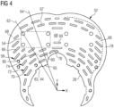
Figure 4 is a view on another embodiment of the anti-vibration bracket and in accordance with the present invention. -
Figure 1 and Figure 2 are opposing views on asubsea equipment assembly 10 comprising afirst component 12, in this example aventuri flow meter 12, and asecond component 14, in this example adifferential pressure sensor 14. Thedifferential pressure sensor 14 is mounted to theventuri flow meter 12 via ananti-vibration bracket 16 and in accordance with the present invention. In this exemplary embodiment of the present invention twodifferential pressure sensors 14 are present. Twodifferential transducers 14 are provided for redundancy purposes. Theventuri flow meter 12 is located along a pipeline (not shown) and which would be bolted to endflanges venturi flow meter 12 has anaxis 18 along which a fluid flows in use. In this example, the direction of the flow of fluid in the pipeline and passing through theventuri flow meter 12 is from left (upstream) to right (downstream) as shown by thearrow 26. Thedifferential pressure sensor 14 is capable of measuring parameters of the fluid flowing through theventuri flow meter 12 such as flow rate and pressure within the fluid. Specifically, thedifferential pressure sensor 14 is measuring the differential pressure in the fluid between an inlet diameter and a restriction in theventuri flow meter 12 as known in the art. - The fluid passing through the pipeline and
venturi flow meter 12 may comprise different fluids such as sea water and oil as well as solids such as sands and gravels. The different densities of the fluid and solids cause eccentric forces as the fluid is accelerated and decelerated through the venturi and which generates the vibrations. The vibrations manifest in the radial or Y-direction and axial (18) or X-direction. - As shown in
Figure 1 a reference axis is shown with X denoting the direction of theaxis 18, Y is the radial direction and Z is a direction perpendicular to X and Z. An axial plane is defined by a plane that is perpendicular to the X direction or theaxis 18. - The
differential pressure sensor 14 is bolted to theanti-vibration bracket 16 via an array ofbolts 24. Theanti-vibration bracket 16 is bolted to theventuri flow meter 12 and extends radially and in an axial plane with respect to theaxis 18. Theanti-vibration bracket 16 is located at an upstream part of theventuri flow meter 12. At a downstream part of theventuri flow meter 12 is located a pair ofbrackets brackets venturi flow meter 12 and extend radially and in an axial plane relative to theaxis 18. Aguard plate brackets anti-vibration bracket 16. Theguard plates subsea equipment assembly 10 from damage such as from drag lines or fishing nets. A radiallyouter part 38 of theguard plates outer part 40 of theanti-vibration bracket 16 are curved such that objects that might otherwise snag are deflected harmlessly over thesubsea equipment assembly 10. Depending on the direction cables approach the differential pressure sensor(s) 14 for example, theanti-vibration bracket 16 may be located at a downstream part of theventuri flow meter 12 and the pair ofbrackets venturi flow meter 12. - Referring now to
Figure 3 andFigure 4 which are views on different embodiments of theanti-vibration bracket 16 and which are in accordance with the present invention. InFigures 3 and4 , like features are denoted by the same reference numbers. In use, fluid passing through theventuri flow meter 12 causes vibrations. Previously, these vibrations can cause damage to components such as thedifferential pressure sensor 14, welds and bolts of thesubsea equipment assembly 10. - The
present anti-vibration bracket 16 is generally plate-like in form and has aplate portion 52 having a thickness. Theanti-vibration bracket 16 is metallic and preferably a stainless steel, but other metals and alloys may be used and particularly those that are resistant to corrosion in harsh environments such as sea water. Theanti-vibration bracket 16 comprises anedge 28 which is a complementary shape to the outer surface 42 (seeFigure 2 ) of theventuri flow meter 12. Theedge 28 is the radially innermost part of theanti-vibration bracket 16 when assembled to thesubsea equipment assembly 10. In these embodiments theplate portion 52 is arranged in an axial plane relative to theaxis 18 and therefore extends generally radially outwardly. In other examples, theanti-vibration bracket 16 may be arranged such that theplate portion 52 is at an angle to the radial direction and the axial plane. - In an assembled state, the
edge 28 is in contact with theouter surface 42 of theventuri flow meter 12, although depending on tolerances or in another embodiment there may be a gap between theedge 28 and theouter surface 42. Theedge 28 comprises a number ofnotches 44 which are provided to accommodate afoot 46.Bolt 48 secures thefoot 46 to theventuri flow meter 12 andbolt 49 secures theanti-vibration bracket 16 and thefoot 46 together. In this example, a cut-out 50 is provided in theedge 28 so that theanti-vibration bracket 16 avoids contact with a lifting hook (not shown) that is fixed to theventuri flow meter 12. In other examples of thepresent anti-vibration bracket 16 there may be no need for a cut-out 50. Further, other attachment means to thefoot 46 may be used and therefore in other examples of theanti-vibration bracket 16 there may be nonotches 44. - The
plate portion 52 comprises anattachment region 54 located a radial distance away from theventuri flow meter 12. Thedifferential pressure sensor 14 is attached to theattachment region 54 via the array of bolts 24 (shown inFigure 2 ). The array ofbolts 24 engage an array of bolt holes 56 provided in theanti-vibration bracket 16 and in this example in theplate portion 52. In this example, two arrays ofbolts 24 and holes 56 are provided for the twodifferential pressure sensors 14 seen inFigures 1 and 2 . It should be appreciated that other attachment means, such as welding, can be used to attach thedifferential pressure sensors 14 to theanti-vibration bracket 16. - The
anti-vibration bracket 16 comprises an array ofslots 58 with individual slots denoted byreference 60. At least some of theslots 60 are located between theventuri flow meter 12 and theattachment region 54. The array ofslots 58 is arranged such that any radial line, e.g.,radial lines slots 60 and either acontact point 65 or an attachment region 63 (of the edge 28) between theanti-vibration bracket 16 and theventuri flow meter 12 or where theanti-vibration bracket 16 is attached to theventuri flow meter 12, i.e. an attachment region 63 and in thiscase notch 44. As mentioned previously, theventuri flow meter 12 is caused to vibrate predominantly in a radial direction because of the fluid passing therethrough. The vibrations are transmitted through theanti-vibration bracket 16 in a radial direction and from or through any point of contact like thecontact point 65 or attachment region 63. The direct radial path of the vibrations passes through at least oneslot 60 so that the vibrations cannot pass directly into theattachment region 54 and thereby cannot pass directly to thedifferential pressure sensor 14. Theattachment region 54 and the differential pressure sensor(s) 14 are at least partly isolated from the source of the vibrations emanating into theanti-vibration bracket 16. The array ofslots 58 provides aregion 80 that is more flexible or of reduced elastic modulus compared to theplate 52 without an array ofslots 58. Theregion 80 is situated between, in a direct line from the source of vibrations, theattachment region 54 and theedge 28 and in particular in aradial line contact point 65 or attachment region 63. Therefore, vibrations from theventuri flow meter 12 are at least partly damped by theanti-vibration bracket 16 before reaching thedifferential pressure sensor 14. In this way, vibrational forces transmitted to thedifferential pressure sensor 14, welds and bolts are reduced and allows these features to have a greater service life and be more reliable than previously. - Vibration damping for the
differential pressure sensor 14 by theanti-vibration bracket 16 is enhanced where at least some of theslots 67 of the array ofslots 58 are located radially outwardly of theattachment region 54. Theseslots 67 further isolate theattachment region 54 such that the region of the plate portion radially outward of theattachment region 54 is more flexible or has a reduced elastic modulus compared to aplate 52 region without an array ofslots 58. Theseslots 67 further dissipate the energy of the vibrations and enhance damping of the vibrations that might reach the differential pressure sensor(s) 14. - Vibration damping by the
anti-vibration bracket 16 is further enhanced where at least some of theslots slots 58 are located to one or bothlateral sides 68 of theattachment region 54. Where there are twodifferential pressure sensors 14 orattachment regions 54, some of theslots 69 are located there between. Theseslots attachment region 54 such that the region of the plate portion laterally of theattachment region 54 is yet more flexible or has yet further reduced elastic modulus compared to aplate 52 region without an array ofslots 58. Theseslots differential pressure sensors 14. - At least some of the
slots 60 of the array ofslots 58 are arranged in at least two rows, e.g.,rows slots 60 in eachrow slot 60. The region of theplate portion 52 having the array ofslots 58 and in particular the spaced apartrows components slot 60 in one row,e.g. row 72, is greater than the gap betweenadjacent slots 60 in another row,e.g. row 70, such that thee is no clear line of sight for vibrations to pass directly to theattachment region 54 as explained above. The length of eachslot 60 in anyrow adjacent slots 60 in any one or more of therows - In general, and as can be seen in
Figure 4 , theslots radial line slot plate 52, and it is preferable that some of theslots slots 58 are arranged such that their longitudinal axis or longest aspect has an angle Θ that is between -60° and +60°, but preferably between -15° and +15° to aradial line slot - The
slots slots 76 may be curved and preferably thecurved slots 76 have a curvature with a constant radius which is a radius from theaxis 18. All of theslots slots 58 may be curved. Thecurved slots 76 can assist in providing more even spacing between each slot in the row ofslots slots - The
slots 60 are shown as elongate and with an aspect ratio > 1, preferably > 2, but in other embodiments theslots 60 may have an aspect ratio of 1. Typically, the aspect ratio, length / width, of at least some of theslots 60 is between 2 and 20. Where, each slot may have an aspect ratio between 2 and 20. Theseslots 60 of the array ofslots 58 are located between thefirst component 12 and theattachment region 54. - The
anti-vibration bracket 16 comprises anedge region 78 where there are no slots, i.e., the array ofslots 58 is not within theedge region 78. This forms a 'picture frame' and provides structural integrity to theanti-vibration bracket 16. - In the Figures, the
slots anti-vibration bracket 16, i.e., the slots are apertures. Theslots slots anti-vibration bracket 16. In this case theslots slots anti-vibration bracket 16 the thinner section remaining within the slot provides theregion 80 that is more flexible or of reduced elastic modulus compared to aplate 52 where there is no array ofslots 58. - All the features disclosed in this specification (including any accompanying claims, abstract and drawings), and/or all the steps of any method or process so disclosed, may be combined in any combination, except combinations where at least some of such features and/or steps are mutually exclusive.
- Each feature disclosed in this specification (including any accompanying claims, abstract and drawings) may be replaced by alternative features serving the same, equivalent or similar purpose, unless expressly stated otherwise. Thus, unless expressly stated otherwise, each feature disclosed is one example only of a generic series of equivalent or similar features.
- The invention is not restricted to the details of the foregoing embodiment(s). The invention extends to any novel one, or any novel combination, of the features disclosed in this specification (including any accompanying claims, abstract and drawings), or to any novel one, or any novel combination, of the steps of any method or process so disclosed.
Claims (15)
- A subsea equipment assembly (10) comprisinga first component (12) having an axis (18),a second component (14) andan anti-vibration bracket (16),the anti-vibration bracket (16) is attached to the first component (12) and the second component (14),in use the first component (12) is caused to vibrate at least in a radial direction relative to the axis (18),the anti-vibration bracket (16) comprises a plate portion (52),the plate portion (52) extends at least radially away from the first component (12) and comprises an attachment region (54) located a radial distance away from the first component (12), the second component (14) is attached to the attachment region (54), whereinthe anti-vibration bracket (16) comprises an array of slots (58), at least some of the slots (60) of the array of slots (58) are located between the first component (12) and the attachment region (54).
- A subsea equipment assembly (10) as claimed in claim 1, wherein
at least some of the slots (67) of the array of slots (58) are located radially outwardly of the attachment region (54). - A subsea equipment assembly (10) as claimed in any one of claims 1-2, wherein
at least some of the slots (66, 69) of the array of slots (58) are located to a lateral side (68) of the attachment region (54). - A subsea equipment assembly (10) as claimed in any one of claims 1-3, wherein
at least some of the slots (66, 67, 69) of the array of slots (58) are arranged in at least one row (70, 72, 74) with respect to the radial direction. - A subsea equipment assembly (10) as claimed in claim 4, wherein
at least some of the slots (66, 67, 69) of the array of slots (58) are arranged in at least two rows (70, 72, 74) with respect to the radial direction. - A subsea equipment assembly (10) as claimed in any one of claims 1-5, wherein
the array of slots (58) is arranged such that any radial line (62, 64) passes through at least one of the slots (60) and either a contact point (65) between the anti-vibration bracket (16) and the first component (12) or where the anti-vibration bracket (16) is attached (63, 44) to the first component (12). - A subsea equipment assembly (10) as claimed in any one of claims 1-6, wherein
at least some of the slots (60, 66, 67, 69) of the array of slots (58) are arranged such that their centreline is at an angle (Θ) to a radial line, the angle (Θ) is between -45° and +45°, preferably between -15° and +15°. - A subsea equipment assembly (10) as claimed in any one of claims 1-7, wherein
at least some of the slots (76) of the array of slots (58) are curved, preferably at least some of the slots (76) of the array of slots (58) have a curvature with a constant radius and preferably a radius from the axis (18). - A subsea equipment assembly (10) as claimed in any one of claims 1-8, wherein
the anti-vibration bracket (16) comprises an edge region (78) and none of the slots the array of slots (58) are within the edge region (78). - A subsea equipment assembly (10) as claimed in any one of claims 1-9, wherein
at least some of slots (60, 66, 67, 69) of the array of slots (58) extend through the anti-vibration bracket (16). - A subsea equipment assembly (10) as claimed in any one of claims 1-9, wherein
at least some of slots (60, 66, 67, 69) of the array of slots (58) extend partly through the anti-vibration bracket (16). - A subsea equipment assembly (10) as claimed in any one of claims 1-7, wherein
the first component (12) is a venturi flow meter (12) and the second component is a differential pressure sensor (14). - A subsea equipment assembly (10) as claimed in any one of claims 1-12, wherein
at least some of the slots (60) of the array of slots (58) have an aspect ratio between and including 2 and 20. - A subsea equipment assembly (10) as claimed in claim 13, wherein
a radial line (62, 64) from the axis (18) passes through the slots (60). - A subsea equipment assembly (10) as claimed in any one of claims 13-14, wherein
the slots (60) are located between the first component (12) and the attachment region (54).
Applications Claiming Priority (1)
| Application Number | Priority Date | Filing Date | Title |
|---|---|---|---|
| GBGB2117208.5A GB202117208D0 (en) | 2021-11-29 | 2021-11-29 | Anti-vibration bracket for subsea equipment |
Publications (3)
| Publication Number | Publication Date |
|---|---|
| EP4194818A2 true EP4194818A2 (en) | 2023-06-14 |
| EP4194818A3 EP4194818A3 (en) | 2023-07-05 |
| EP4194818B1 EP4194818B1 (en) | 2025-08-13 |
Family
ID=80038616
Family Applications (1)
| Application Number | Title | Priority Date | Filing Date |
|---|---|---|---|
| EP22195460.5A Active EP4194818B1 (en) | 2021-11-29 | 2022-09-13 | Anti-vibration bracket for subsea equipment |
Country Status (3)
| Country | Link |
|---|---|
| US (1) | US12449091B2 (en) |
| EP (1) | EP4194818B1 (en) |
| GB (1) | GB202117208D0 (en) |
Family Cites Families (16)
| Publication number | Priority date | Publication date | Assignee | Title |
|---|---|---|---|---|
| FR2473654A1 (en) * | 1979-10-12 | 1981-07-17 | Nat Res Dev | METHOD OF STABILIZING EXHAUSTED STRUCTURES WITH RESPECT TO PERTURBATIONS CAUSED BY A SURFACE FLUID AND STABILIZED VERTICAL STRUCTURE |
| US4657116A (en) * | 1982-03-04 | 1987-04-14 | Exxon Production Research Co. | Vibration-isolating apparatus |
| US4705331A (en) * | 1985-01-11 | 1987-11-10 | Wayne Graham & Associates International, Inc. | Subsea clamping apparatus |
| US6220563B1 (en) * | 1995-06-15 | 2001-04-24 | John Cunningham | Vibration isolation device and method |
| JP2000168676A (en) * | 1998-10-02 | 2000-06-20 | Mitsubishi Heavy Ind Ltd | Offshore structures |
| FR2855478B1 (en) | 2003-06-02 | 2005-08-19 | Valeo Systemes Dessuyage | AUTOMOTIVE VEHICLE EQUIPMENT COMPONENT WITH VIBRATION DAMPER FASTENING POINTS |
| NO322675B1 (en) * | 2004-05-18 | 2006-11-27 | Aibel As | Viscoelastic dampers in rudder system |
| FR2896021B1 (en) | 2006-01-12 | 2008-03-28 | Hutchinson Sa | ANTI-VIBRATION CONNECTION DEVICE, CONNECTING LINK COMPRISING SUCH A CONNECTING DEVICE AND METHOD OF MANUFACTURING SUCH ANTIVIBRATION DEVICE |
| JP2012097878A (en) * | 2010-11-05 | 2012-05-24 | Kurashiki Kako Co Ltd | Vibration control connecting rod |
| US9046396B2 (en) * | 2013-03-15 | 2015-06-02 | Dieterich Standard, Inc. | Process variable measurement using universal flow technology connection platform |
| US10788094B2 (en) * | 2014-10-08 | 2020-09-29 | Sercel, Inc. | Apparatus and method for vibration mitigation with dynamic vibration absorber |
| TWI641770B (en) * | 2017-10-13 | 2018-11-21 | 謝榮寬 | Tie plate and tie device |
| CN107781509B (en) * | 2017-11-17 | 2023-10-13 | 长沙矿山研究院有限责任公司 | A sit-tube underwater working device |
| US11118723B2 (en) * | 2019-05-24 | 2021-09-14 | Chicago Maritme Supply, LLC | Mounting plate for computer |
| CN209745511U (en) * | 2019-06-17 | 2019-12-06 | 中机试验装备股份有限公司 | Pipeline resonance fatigue test bench |
| CN213021751U (en) * | 2020-10-28 | 2021-04-20 | 天津中天鑫宇科技有限公司 | Flowmeter suitable for various pipelines |
-
2021
- 2021-11-29 GB GBGB2117208.5A patent/GB202117208D0/en not_active Ceased
-
2022
- 2022-09-13 EP EP22195460.5A patent/EP4194818B1/en active Active
- 2022-11-03 US US17/980,290 patent/US12449091B2/en active Active
Also Published As
| Publication number | Publication date |
|---|---|
| EP4194818B1 (en) | 2025-08-13 |
| US20230167942A1 (en) | 2023-06-01 |
| US12449091B2 (en) | 2025-10-21 |
| EP4194818A3 (en) | 2023-07-05 |
| GB202117208D0 (en) | 2022-01-12 |
Similar Documents
| Publication | Publication Date | Title |
|---|---|---|
| US8500367B2 (en) | Suppression of vortex induced vibration | |
| US7070361B2 (en) | Apparatus and methods for providing VIV suppression to a riser system comprising umbilical elements | |
| EP3414484B1 (en) | Vibration damper for pipes | |
| US5421413A (en) | Flexible fairings to reduce vortex-induced vibrations | |
| EP0933620A1 (en) | Fluid flow system, casing , and method | |
| US20060021560A1 (en) | Tail fairing designed with features for fast installation and/or for suppression of vortices addition between fairings, apparatus incorporating such fairings, methods of making and using such fairings and apparatus, and methods of installing such fairings | |
| JP6033194B2 (en) | Coriolis mass flow meter | |
| CN103443498B (en) | Damper systems, jumper systems and subsea resource extraction systems | |
| US12618499B2 (en) | Gimbals and their manufacture | |
| US10329935B2 (en) | Guide arm for elements having an elongated shape, in particular for a turbomachine | |
| EP4194818B1 (en) | Anti-vibration bracket for subsea equipment | |
| CN105378213A (en) | Pipe components and methods of manufacture | |
| US10808874B2 (en) | Inline fluid damper device | |
| KR102455878B1 (en) | Vortex induced vibration reducing apparatus | |
| KR101275154B1 (en) | Noise reduction assembly of piping for hull | |
| JP5964286B2 (en) | Heat exchanger | |
| JP6089749B2 (en) | gasket | |
| EP1807650A1 (en) | Visco elastic damping in a piping system | |
| CN116717655B (en) | A vibration damping device for riser vortex-induced vibration and a design method for the vibration damping device. | |
| JP7863320B2 (en) | Method for reducing vortex excitation vibration in multiple riser tubes, multiple riser tube system for reducing vortex excitation vibration, and phase-changing joint and asymmetrical arrangement bracket for multiple riser tube system. | |
| Xuan et al. | Experimental Study About Vibration Interference of Dual Pipe Systems | |
| EP4279784A1 (en) | Pipeline provided with silencing structure | |
| CN118959764A (en) | A multi-directional displacement vibration damping spring support and hanger | |
| KR102560685B1 (en) | power transmission device | |
| Lato | Passive damping mechanism of Herschel-Quincke tubes for pressure pulsations in piping systems |
Legal Events
| Date | Code | Title | Description |
|---|---|---|---|
| PUAI | Public reference made under article 153(3) epc to a published international application that has entered the european phase |
Free format text: ORIGINAL CODE: 0009012 |
|
| STAA | Information on the status of an ep patent application or granted ep patent |
Free format text: STATUS: THE APPLICATION HAS BEEN PUBLISHED |
|
| STAA | Information on the status of an ep patent application or granted ep patent |
Free format text: STATUS: REQUEST FOR EXAMINATION WAS MADE |
|
| PUAL | Search report despatched |
Free format text: ORIGINAL CODE: 0009013 |
|
| AK | Designated contracting states |
Kind code of ref document: A2 Designated state(s): AL AT BE BG CH CY CZ DE DK EE ES FI FR GB GR HR HU IE IS IT LI LT LU LV MC MK MT NL NO PL PT RO RS SE SI SK SM TR |
|
| 17P | Request for examination filed |
Effective date: 20230523 |
|
| RBV | Designated contracting states (corrected) |
Designated state(s): AL AT BE BG CH CY CZ DE DK EE ES FI FR GB GR HR HU IE IS IT LI LT LU LV MC MK MT NL NO PL PT RO RS SE SI SK SM TR |
|
| AK | Designated contracting states |
Kind code of ref document: A3 Designated state(s): AL AT BE BG CH CY CZ DE DK EE ES FI FR GB GR HR HU IE IS IT LI LT LU LV MC MK MT NL NO PL PT RO RS SE SI SK SM TR |
|
| RIC1 | Information provided on ipc code assigned before grant |
Ipc: G01F 15/18 20060101ALI20230601BHEP Ipc: G01F 1/44 20060101ALI20230601BHEP Ipc: F16L 1/12 20060101ALI20230601BHEP Ipc: F16F 15/00 20060101ALI20230601BHEP Ipc: F16F 7/00 20060101ALI20230601BHEP Ipc: E21B 43/01 20060101ALI20230601BHEP Ipc: E21B 41/08 20060101ALI20230601BHEP Ipc: E21B 41/00 20060101ALI20230601BHEP Ipc: G01F 1/36 20060101AFI20230601BHEP Ipc: E21B 33/035 20060101ALI20230601BHEP |
|
| REG | Reference to a national code |
Ref country code: DE Ref legal event code: R079 Free format text: PREVIOUS MAIN CLASS: G01F0001360000 Ipc: F16F0015060000 Ref country code: DE Ref legal event code: R079 Ref document number: 602022019293 Country of ref document: DE Free format text: PREVIOUS MAIN CLASS: G01F0001360000 Ipc: F16F0015060000 |
|
| GRAP | Despatch of communication of intention to grant a patent |
Free format text: ORIGINAL CODE: EPIDOSNIGR1 |
|
| STAA | Information on the status of an ep patent application or granted ep patent |
Free format text: STATUS: GRANT OF PATENT IS INTENDED |
|
| INTG | Intention to grant announced |
Effective date: 20250331 |
|
| RIC1 | Information provided on ipc code assigned before grant |
Ipc: G01F 15/18 20060101ALI20250321BHEP Ipc: F16L 1/12 20060101ALI20250321BHEP Ipc: F16F 7/00 20060101ALI20250321BHEP Ipc: G01F 1/44 20060101ALI20250321BHEP Ipc: G01F 1/36 20060101ALI20250321BHEP Ipc: F16F 15/06 20060101AFI20250321BHEP |
|
| GRAS | Grant fee paid |
Free format text: ORIGINAL CODE: EPIDOSNIGR3 |
|
| GRAA | (expected) grant |
Free format text: ORIGINAL CODE: 0009210 |
|
| STAA | Information on the status of an ep patent application or granted ep patent |
Free format text: STATUS: THE PATENT HAS BEEN GRANTED |
|
| AK | Designated contracting states |
Kind code of ref document: B1 Designated state(s): AL AT BE BG CH CY CZ DE DK EE ES FI FR GB GR HR HU IE IS IT LI LT LU LV MC MK MT NL NO PL PT RO RS SE SI SK SM TR |
|
| REG | Reference to a national code |
Ref country code: GB Ref legal event code: FG4D |
|
| REG | Reference to a national code |
Ref country code: CH Ref legal event code: EP |
|
| REG | Reference to a national code |
Ref country code: DE Ref legal event code: R096 Ref document number: 602022019293 Country of ref document: DE |
|
| REG | Reference to a national code |
Ref country code: IE Ref legal event code: FG4D |
|
| PGFP | Annual fee paid to national office [announced via postgrant information from national office to epo] |
Ref country code: DE Payment date: 20250926 Year of fee payment: 4 |
|
| PGFP | Annual fee paid to national office [announced via postgrant information from national office to epo] |
Ref country code: FR Payment date: 20250925 Year of fee payment: 4 Ref country code: AT Payment date: 20251020 Year of fee payment: 4 |
|
| REG | Reference to a national code |
Ref country code: NL Ref legal event code: MP Effective date: 20250813 |
|
| PG25 | Lapsed in a contracting state [announced via postgrant information from national office to epo] |
Ref country code: IS Free format text: LAPSE BECAUSE OF FAILURE TO SUBMIT A TRANSLATION OF THE DESCRIPTION OR TO PAY THE FEE WITHIN THE PRESCRIBED TIME-LIMIT Effective date: 20251213 |
|
| PGFP | Annual fee paid to national office [announced via postgrant information from national office to epo] |
Ref country code: NO Payment date: 20250917 Year of fee payment: 4 |
|
| REG | Reference to a national code |
Ref country code: LT Ref legal event code: MG9D |
|
| PG25 | Lapsed in a contracting state [announced via postgrant information from national office to epo] |
Ref country code: PT Free format text: LAPSE BECAUSE OF FAILURE TO SUBMIT A TRANSLATION OF THE DESCRIPTION OR TO PAY THE FEE WITHIN THE PRESCRIBED TIME-LIMIT Effective date: 20251215 |
|
| PG25 | Lapsed in a contracting state [announced via postgrant information from national office to epo] |
Ref country code: FI Free format text: LAPSE BECAUSE OF FAILURE TO SUBMIT A TRANSLATION OF THE DESCRIPTION OR TO PAY THE FEE WITHIN THE PRESCRIBED TIME-LIMIT Effective date: 20250813 |
|
| PG25 | Lapsed in a contracting state [announced via postgrant information from national office to epo] |
Ref country code: HR Free format text: LAPSE BECAUSE OF FAILURE TO SUBMIT A TRANSLATION OF THE DESCRIPTION OR TO PAY THE FEE WITHIN THE PRESCRIBED TIME-LIMIT Effective date: 20250813 Ref country code: NL Free format text: LAPSE BECAUSE OF FAILURE TO SUBMIT A TRANSLATION OF THE DESCRIPTION OR TO PAY THE FEE WITHIN THE PRESCRIBED TIME-LIMIT Effective date: 20250813 |
|
| PG25 | Lapsed in a contracting state [announced via postgrant information from national office to epo] |
Ref country code: GR Free format text: LAPSE BECAUSE OF FAILURE TO SUBMIT A TRANSLATION OF THE DESCRIPTION OR TO PAY THE FEE WITHIN THE PRESCRIBED TIME-LIMIT Effective date: 20251114 |
|
| PG25 | Lapsed in a contracting state [announced via postgrant information from national office to epo] |
Ref country code: SE Free format text: LAPSE BECAUSE OF FAILURE TO SUBMIT A TRANSLATION OF THE DESCRIPTION OR TO PAY THE FEE WITHIN THE PRESCRIBED TIME-LIMIT Effective date: 20250813 |
|
| PG25 | Lapsed in a contracting state [announced via postgrant information from national office to epo] |
Ref country code: LV Free format text: LAPSE BECAUSE OF FAILURE TO SUBMIT A TRANSLATION OF THE DESCRIPTION OR TO PAY THE FEE WITHIN THE PRESCRIBED TIME-LIMIT Effective date: 20250813 |
|
| PG25 | Lapsed in a contracting state [announced via postgrant information from national office to epo] |
Ref country code: BG Free format text: LAPSE BECAUSE OF FAILURE TO SUBMIT A TRANSLATION OF THE DESCRIPTION OR TO PAY THE FEE WITHIN THE PRESCRIBED TIME-LIMIT Effective date: 20250813 Ref country code: PL Free format text: LAPSE BECAUSE OF FAILURE TO SUBMIT A TRANSLATION OF THE DESCRIPTION OR TO PAY THE FEE WITHIN THE PRESCRIBED TIME-LIMIT Effective date: 20250813 |
|
| PG25 | Lapsed in a contracting state [announced via postgrant information from national office to epo] |
Ref country code: RS Free format text: LAPSE BECAUSE OF FAILURE TO SUBMIT A TRANSLATION OF THE DESCRIPTION OR TO PAY THE FEE WITHIN THE PRESCRIBED TIME-LIMIT Effective date: 20251113 |
|
| PG25 | Lapsed in a contracting state [announced via postgrant information from national office to epo] |
Ref country code: ES Free format text: LAPSE BECAUSE OF FAILURE TO SUBMIT A TRANSLATION OF THE DESCRIPTION OR TO PAY THE FEE WITHIN THE PRESCRIBED TIME-LIMIT Effective date: 20250813 |
|
| REG | Reference to a national code |
Ref country code: AT Ref legal event code: MK05 Ref document number: 1824930 Country of ref document: AT Kind code of ref document: T Effective date: 20250813 |
|
| PG25 | Lapsed in a contracting state [announced via postgrant information from national office to epo] |
Ref country code: RO Free format text: LAPSE BECAUSE OF FAILURE TO SUBMIT A TRANSLATION OF THE DESCRIPTION OR TO PAY THE FEE WITHIN THE PRESCRIBED TIME-LIMIT Effective date: 20250813 |
|
| PG25 | Lapsed in a contracting state [announced via postgrant information from national office to epo] |
Ref country code: SM Free format text: LAPSE BECAUSE OF FAILURE TO SUBMIT A TRANSLATION OF THE DESCRIPTION OR TO PAY THE FEE WITHIN THE PRESCRIBED TIME-LIMIT Effective date: 20250813 |
|
| PG25 | Lapsed in a contracting state [announced via postgrant information from national office to epo] |
Ref country code: DK Free format text: LAPSE BECAUSE OF FAILURE TO SUBMIT A TRANSLATION OF THE DESCRIPTION OR TO PAY THE FEE WITHIN THE PRESCRIBED TIME-LIMIT Effective date: 20250813 |
|
| PG25 | Lapsed in a contracting state [announced via postgrant information from national office to epo] |
Ref country code: AT Free format text: LAPSE BECAUSE OF FAILURE TO SUBMIT A TRANSLATION OF THE DESCRIPTION OR TO PAY THE FEE WITHIN THE PRESCRIBED TIME-LIMIT Effective date: 20250813 |
|
| PG25 | Lapsed in a contracting state [announced via postgrant information from national office to epo] |
Ref country code: IT Free format text: LAPSE BECAUSE OF FAILURE TO SUBMIT A TRANSLATION OF THE DESCRIPTION OR TO PAY THE FEE WITHIN THE PRESCRIBED TIME-LIMIT Effective date: 20250813 |
|
| PG25 | Lapsed in a contracting state [announced via postgrant information from national office to epo] |
Ref country code: CZ Free format text: LAPSE BECAUSE OF FAILURE TO SUBMIT A TRANSLATION OF THE DESCRIPTION OR TO PAY THE FEE WITHIN THE PRESCRIBED TIME-LIMIT Effective date: 20250813 |
|
| PG25 | Lapsed in a contracting state [announced via postgrant information from national office to epo] |
Ref country code: EE Free format text: LAPSE BECAUSE OF FAILURE TO SUBMIT A TRANSLATION OF THE DESCRIPTION OR TO PAY THE FEE WITHIN THE PRESCRIBED TIME-LIMIT Effective date: 20250813 Ref country code: SK Free format text: LAPSE BECAUSE OF FAILURE TO SUBMIT A TRANSLATION OF THE DESCRIPTION OR TO PAY THE FEE WITHIN THE PRESCRIBED TIME-LIMIT Effective date: 20250813 |
|
| REG | Reference to a national code |
Ref country code: CH Ref legal event code: H13 Free format text: ST27 STATUS EVENT CODE: U-0-0-H10-H13 (AS PROVIDED BY THE NATIONAL OFFICE) Effective date: 20260504 |
|
| REG | Reference to a national code |
Ref country code: DE Ref legal event code: R097 Ref document number: 602022019293 Country of ref document: DE |
|
| PG25 | Lapsed in a contracting state [announced via postgrant information from national office to epo] |
Ref country code: LU Free format text: LAPSE BECAUSE OF NON-PAYMENT OF DUE FEES Effective date: 20250913 |
|
| REG | Reference to a national code |
Ref country code: BE Ref legal event code: MM Effective date: 20250930 |
|
| PLBE | No opposition filed within time limit |
Free format text: ORIGINAL CODE: 0009261 |
|
| STAA | Information on the status of an ep patent application or granted ep patent |
Free format text: STATUS: NO OPPOSITION FILED WITHIN TIME LIMIT |
|
| REG | Reference to a national code |
Ref country code: CH Ref legal event code: L10 Free format text: ST27 STATUS EVENT CODE: U-0-0-L10-L00 (AS PROVIDED BY THE NATIONAL OFFICE) Effective date: 20260624 |
|
| PG25 | Lapsed in a contracting state [announced via postgrant information from national office to epo] |
Ref country code: LT Free format text: LAPSE BECAUSE OF FAILURE TO SUBMIT A TRANSLATION OF THE DESCRIPTION OR TO PAY THE FEE WITHIN THE PRESCRIBED TIME-LIMIT Effective date: 20250813 Ref country code: MC Free format text: LAPSE BECAUSE OF FAILURE TO SUBMIT A TRANSLATION OF THE DESCRIPTION OR TO PAY THE FEE WITHIN THE PRESCRIBED TIME-LIMIT Effective date: 20250813 |
|
| PG25 | Lapsed in a contracting state [announced via postgrant information from national office to epo] |
Ref country code: BE Free format text: LAPSE BECAUSE OF NON-PAYMENT OF DUE FEES Effective date: 20250930 Ref country code: IE Free format text: LAPSE BECAUSE OF NON-PAYMENT OF DUE FEES Effective date: 20250913 Ref country code: CH Free format text: LAPSE BECAUSE OF NON-PAYMENT OF DUE FEES Effective date: 20250930 |
|
| 26N | No opposition filed |
Effective date: 20260515 |