EP4194696A1 - Compressor - Google Patents
Compressor Download PDFInfo
- Publication number
- EP4194696A1 EP4194696A1 EP21866511.5A EP21866511A EP4194696A1 EP 4194696 A1 EP4194696 A1 EP 4194696A1 EP 21866511 A EP21866511 A EP 21866511A EP 4194696 A1 EP4194696 A1 EP 4194696A1
- Authority
- EP
- European Patent Office
- Prior art keywords
- flow path
- casing
- gas
- motor
- compressor
- Prior art date
- Legal status (The legal status is an assumption and is not a legal conclusion. Google has not performed a legal analysis and makes no representation as to the accuracy of the status listed.)
- Granted
Links
Images



Classifications
-
- F—MECHANICAL ENGINEERING; LIGHTING; HEATING; WEAPONS; BLASTING
- F04—POSITIVE - DISPLACEMENT MACHINES FOR LIQUIDS; PUMPS FOR LIQUIDS OR ELASTIC FLUIDS
- F04B—POSITIVE-DISPLACEMENT MACHINES FOR LIQUIDS; PUMPS
- F04B39/00—Component parts, details, or accessories, of pumps or pumping systems specially adapted for elastic fluids, not otherwise provided for in, or of interest apart from, groups F04B25/00 - F04B37/00
- F04B39/06—Cooling; Heating; Prevention of freezing
-
- F—MECHANICAL ENGINEERING; LIGHTING; HEATING; WEAPONS; BLASTING
- F04—POSITIVE - DISPLACEMENT MACHINES FOR LIQUIDS; PUMPS FOR LIQUIDS OR ELASTIC FLUIDS
- F04B—POSITIVE-DISPLACEMENT MACHINES FOR LIQUIDS; PUMPS
- F04B35/00—Piston pumps specially adapted for elastic fluids and characterised by the driving means to their working members, or by combination with, or adaptation to, specific driving engines or motors, not otherwise provided for
- F04B35/04—Piston pumps specially adapted for elastic fluids and characterised by the driving means to their working members, or by combination with, or adaptation to, specific driving engines or motors, not otherwise provided for the means being electric
-
- F—MECHANICAL ENGINEERING; LIGHTING; HEATING; WEAPONS; BLASTING
- F04—POSITIVE - DISPLACEMENT MACHINES FOR LIQUIDS; PUMPS FOR LIQUIDS OR ELASTIC FLUIDS
- F04B—POSITIVE-DISPLACEMENT MACHINES FOR LIQUIDS; PUMPS
- F04B39/00—Component parts, details, or accessories, of pumps or pumping systems specially adapted for elastic fluids, not otherwise provided for in, or of interest apart from, groups F04B25/00 - F04B37/00
- F04B39/12—Casings; Cylinders; Cylinder heads; Fluid connections
- F04B39/121—Casings
-
- F—MECHANICAL ENGINEERING; LIGHTING; HEATING; WEAPONS; BLASTING
- F04—POSITIVE - DISPLACEMENT MACHINES FOR LIQUIDS; PUMPS FOR LIQUIDS OR ELASTIC FLUIDS
- F04B—POSITIVE-DISPLACEMENT MACHINES FOR LIQUIDS; PUMPS
- F04B39/00—Component parts, details, or accessories, of pumps or pumping systems specially adapted for elastic fluids, not otherwise provided for in, or of interest apart from, groups F04B25/00 - F04B37/00
- F04B39/12—Casings; Cylinders; Cylinder heads; Fluid connections
- F04B39/123—Fluid connections
-
- F—MECHANICAL ENGINEERING; LIGHTING; HEATING; WEAPONS; BLASTING
- F04—POSITIVE - DISPLACEMENT MACHINES FOR LIQUIDS; PUMPS FOR LIQUIDS OR ELASTIC FLUIDS
- F04C—ROTARY-PISTON, OR OSCILLATING-PISTON, POSITIVE-DISPLACEMENT MACHINES FOR LIQUIDS; ROTARY-PISTON, OR OSCILLATING-PISTON, POSITIVE-DISPLACEMENT PUMPS
- F04C18/00—Rotary-piston pumps specially adapted for elastic fluids
- F04C18/02—Rotary-piston pumps specially adapted for elastic fluids of arcuate-engagement type, i.e. with circular translatory movement of co-operating members, each member having the same number of teeth or tooth-equivalents
- F04C18/0207—Rotary-piston pumps specially adapted for elastic fluids of arcuate-engagement type, i.e. with circular translatory movement of co-operating members, each member having the same number of teeth or tooth-equivalents both members having co-operating elements in spiral form
- F04C18/0215—Rotary-piston pumps specially adapted for elastic fluids of arcuate-engagement type, i.e. with circular translatory movement of co-operating members, each member having the same number of teeth or tooth-equivalents both members having co-operating elements in spiral form where only one member is moving
-
- F—MECHANICAL ENGINEERING; LIGHTING; HEATING; WEAPONS; BLASTING
- F04—POSITIVE - DISPLACEMENT MACHINES FOR LIQUIDS; PUMPS FOR LIQUIDS OR ELASTIC FLUIDS
- F04C—ROTARY-PISTON, OR OSCILLATING-PISTON, POSITIVE-DISPLACEMENT MACHINES FOR LIQUIDS; ROTARY-PISTON, OR OSCILLATING-PISTON, POSITIVE-DISPLACEMENT PUMPS
- F04C23/00—Combinations of two or more pumps, each being of rotary-piston or oscillating-piston type, specially adapted for elastic fluids; Pumping installations specially adapted for elastic fluids; Multi-stage pumps specially adapted for elastic fluids
- F04C23/008—Hermetic pumps
-
- F—MECHANICAL ENGINEERING; LIGHTING; HEATING; WEAPONS; BLASTING
- F04—POSITIVE - DISPLACEMENT MACHINES FOR LIQUIDS; PUMPS FOR LIQUIDS OR ELASTIC FLUIDS
- F04C—ROTARY-PISTON, OR OSCILLATING-PISTON, POSITIVE-DISPLACEMENT MACHINES FOR LIQUIDS; ROTARY-PISTON, OR OSCILLATING-PISTON, POSITIVE-DISPLACEMENT PUMPS
- F04C29/00—Component parts, details or accessories of pumps or pumping installations, not provided for in groups F04C18/00 - F04C28/00
- F04C29/02—Lubrication; Lubricant separation
- F04C29/026—Lubricant separation
-
- F—MECHANICAL ENGINEERING; LIGHTING; HEATING; WEAPONS; BLASTING
- F04—POSITIVE - DISPLACEMENT MACHINES FOR LIQUIDS; PUMPS FOR LIQUIDS OR ELASTIC FLUIDS
- F04C—ROTARY-PISTON, OR OSCILLATING-PISTON, POSITIVE-DISPLACEMENT MACHINES FOR LIQUIDS; ROTARY-PISTON, OR OSCILLATING-PISTON, POSITIVE-DISPLACEMENT PUMPS
- F04C2240/00—Components
- F04C2240/30—Casings or housings
-
- F—MECHANICAL ENGINEERING; LIGHTING; HEATING; WEAPONS; BLASTING
- F04—POSITIVE - DISPLACEMENT MACHINES FOR LIQUIDS; PUMPS FOR LIQUIDS OR ELASTIC FLUIDS
- F04C—ROTARY-PISTON, OR OSCILLATING-PISTON, POSITIVE-DISPLACEMENT MACHINES FOR LIQUIDS; ROTARY-PISTON, OR OSCILLATING-PISTON, POSITIVE-DISPLACEMENT PUMPS
- F04C2240/00—Components
- F04C2240/40—Electric motor
-
- F—MECHANICAL ENGINEERING; LIGHTING; HEATING; WEAPONS; BLASTING
- F04—POSITIVE - DISPLACEMENT MACHINES FOR LIQUIDS; PUMPS FOR LIQUIDS OR ELASTIC FLUIDS
- F04C—ROTARY-PISTON, OR OSCILLATING-PISTON, POSITIVE-DISPLACEMENT MACHINES FOR LIQUIDS; ROTARY-PISTON, OR OSCILLATING-PISTON, POSITIVE-DISPLACEMENT PUMPS
- F04C29/00—Component parts, details or accessories of pumps or pumping installations, not provided for in groups F04C18/00 - F04C28/00
- F04C29/04—Heating; Cooling; Heat insulation
-
- F—MECHANICAL ENGINEERING; LIGHTING; HEATING; WEAPONS; BLASTING
- F04—POSITIVE - DISPLACEMENT MACHINES FOR LIQUIDS; PUMPS FOR LIQUIDS OR ELASTIC FLUIDS
- F04C—ROTARY-PISTON, OR OSCILLATING-PISTON, POSITIVE-DISPLACEMENT MACHINES FOR LIQUIDS; ROTARY-PISTON, OR OSCILLATING-PISTON, POSITIVE-DISPLACEMENT PUMPS
- F04C29/00—Component parts, details or accessories of pumps or pumping installations, not provided for in groups F04C18/00 - F04C28/00
- F04C29/12—Arrangements for admission or discharge of the working fluid, e.g. constructional features of the inlet or outlet
Definitions
- the present disclosure relates to a compressor.
- a compressor that has been known in the art includes a flow regulating member for diverting a gas sucked into a casing.
- a compressor of this type is described, for example, in Patent Document 1.
- the compressor of Patent Document 1 includes a closed container, an electric motor element, a compression mechanism section driven by the electric motor element, a suction pipe through which a refrigerant is sucked into the closed container, and a regulating vane that diverts the refrigerant sucked through the suction pipe.
- a first opening through which one of two streams of the refrigerant diverted by the regulating vane passes is formed toward the compressor section.
- a second opening through which the other stream passes is formed toward the electric motor element.
- the compressor of Patent Document 1 can cool the electric motor element as well as the compressor section.
- Patent Document 1 Japanese Unexamined Patent Publication No. 2018-131910 (in particular, paragraphs 0012, 0030)
- the refrigerant from the second opening of the regulating vane is adequately supplied to a region of the compressor of Patent Document 1 near one axial end of the electric motor element (near the compression element)
- the refrigerant may be inadequately supplied to a region thereof near the other axial end of the electric motor element (remote from the compression element).
- the region near the other axial end of the motor may be inadequately cooled.
- a first aspect of the present disclosure is directed to a compressor (1) including: a casing (10) having a tubular shape; a compression mechanism (14); a motor (6); a suction pipe (18); a gas flow path (91); and a gas guide (80).
- the compression mechanism (14) is arranged near one end of the casing (10) in the casing (10) to compress a gas.
- the motor (6) is arranged near another end of the casing (10) in the casing (10) to drive the compression mechanism (14).
- the suction pipe (18) opens between the compression mechanism (14) and the motor (6) in the casing (10).
- the gas flow path (91) is formed between the motor (6) and an inner peripheral surface of the casing (10), and allows an internal region of the casing (10) near one axial end of the motor (6) and another internal region of the casing (10) near another axial end of the motor (6) to communicate with each other.
- the gas guide (80) faces an open end (18A) of the suction pipe (18) in the casing (10), and includes a first flow path (83) and a second flow path (84).
- the first flow path (83) is configured to guide a portion of a gas that has passed through the suction pipe (18) toward the compression mechanism (14).
- the second flow path (84) is configured to guide a remaining portion of the gas that has passed through the suction pipe (18) toward the gas flow path (91).
- a portion of the gas sucked through the suction pipe (18) is guided to the gas flow path (91) by the second flow path (84) of the gas guide (80), and is supplied through the gas flow path (91) toward the another axial end of the motor (6).
- a portion of the motor (6) near the another axial end is cooled by the gas that has passed through the gas flow path (91).
- the temperature difference between the one axial end and the another axial end of the motor (6) decreases, thus improving the reliability of the motor (6).
- a second aspect of the present disclosure is an embodiment of the first aspect.
- a minimum flow path cross-sectional area of the first flow path (83) is larger than a minimum flow path cross-sectional area of the second flow path (84).
- the second aspect allows the gas sucked through the suction pipe (18) to flow more easily toward the compression mechanism (14) than toward the motor (6). This can prevent an adverse effect caused by the gas flowing excessively toward the motor (6).
- a third aspect of the present disclosure is an embodiment of the first or second aspect.
- the second flow path (84) includes a tapered portion (85) and a reverse tapered portion (86).
- the tapered portion (85) has a flow path cross-sectional area that decreases toward an outlet of the second flow path (84).
- the reverse tapered portion (86) is closer to the outlet of the second flow path (84) than the tapered portion (85) is.
- the reverse tapered portion (86) has a flow path cross-sectional area that increases toward the outlet of the second flow path (84).
- the second flow path (84) has the narrowed portion (88) at the joint between the tapered portion (85) and the reverse tapered portion (86). This limits the amount of the gas flowing toward the motor (6).
- Spreading the gas that has passed through the narrowed portion (88) along the surface of the gas guide (80) lowers the velocity of flow of the gas. As a result, the velocity of flow of the gas flowing toward the motor (6) can be lowered. For example, if an oil reservoir is closer to the another end of the casing (10) than the motor (6) of the compressor (1) is, oil in the oil reservoir can be prevented from being scattered by the gas flow.
- a fourth aspect of the present disclosure is an embodiment of any one of the first to third aspects.
- an outlet of the second flow path (84) faces a first open end (91A) of the gas flow path (91) near the gas guide (80).
- the fourth aspect allows the gas flowing through the second flow path (84) to flow efficiently to the gas flow path (91).
- a fifth aspect of the present disclosure is an embodiment of the fourth aspect.
- the outlet of the second flow path (84) overlaps with an entirety of the first open end (91A) of the gas flow path (91) as viewed in an axial direction of the casing (10).
- the gas that has flowed through the second flow path (84) can be kept from flowing excessively to the gas flow path (91). This can prevent an adverse effect caused by the gas flowing excessively toward the motor (6).
- a scroll compressor (1) is connected to a refrigerant circuit through which a refrigerant gas circulates to perform a refrigeration cycle, and compresses the refrigerant gas serving as a working fluid.
- the scroll compressor (1) is used, for example, in an air conditioner or a refrigeration apparatus.
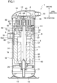
- FIG. 1 is a longitudinal sectional view of the scroll compressor (1).
- the scroll compressor (1) is a hermetic compressor, and mainly includes a casing (10), a compression mechanism (14), a motor (6), a drive shaft (7), a lower bearing (21), a partition plate (26), an suction pipe (18), and a discharge pipe (19).
- the casing (10) is a closed container with both ends closed.
- the casing (10) has a vertically long cylindrical shape with an axis parallel to the top-to-bottom direction.
- the casing (10) includes a barrel (11), an upper end plate (12), and a lower end plate (13).
- the barrel (11) has a cylindrical shape with an axis oriented in the top-to-bottom direction.
- the upper end plate (12) has a convex surface protruding upward in a bowl shape.
- the upper end plate (12) is airtightly welded to, and integrally bonded to, an upper end portion of the barrel (11).
- the lower end plate (13) has a convex surface protruding downward in a bowl shape.
- the lower end plate (13) is airtightly welded to, and integrally bonded to, a lower end portion of the barrel (11).
- the compression mechanism (14), the motor (6), the lower bearing (21), and the partition plate (26) are arranged in the casing (10).
- the compression mechanism (14) is arranged near an upper end of the interior of the casing (10).
- the motor (6) is arranged near a lower end of the interior of the casing (10).
- the lower bearing (21) is arranged closer to the lower end of the interior of the casing (10) than the motor (6) is.
- the partition plate (26) is arranged radially outside the lower bearing (21) in the casing (10).
- the partition plate (26) is arranged below the motor (6) in the casing (10).
- the drive shaft (7) is housed in the casing (10) such that the direction of its axis corresponds to the direction of the axis of the barrel (11).
- the compression mechanism (14) compresses the refrigerant gas introduced into the casing (10).
- the motor (6) drives the compression mechanism (14). Specifically, the motor (6) rotates the drive shaft (7), which rotates a movable scroll (5), described later, to drive the compression mechanism (14).
- the casing (10) has, at its bottom, an oil reservoir (15) for storing lubricant.
- the partition plate (26) covers the lubricant stored at the bottom of the casing (10) from above.
- the suction pipe (18) is provided for the barrel (11) of the casing (10).
- the suction pipe (18) introduces the refrigerant gas in the refrigerant circuit into the casing (10).
- the suction pipe (18) opens between the compression mechanism (14) and the motor (6) in the casing (10).
- the suction pipe (18) connects the inside and outside of the barrel (11) together.
- the discharge pipe (19) is provided at the top of the casing (10).
- the discharge pipe (19) delivers the refrigerant gas compressed by the compression mechanism (14) to the refrigerant circuit.
- the discharge pipe (19) connects the inside and outside of the upper end plate (12) together.
- the drive shaft (7) has a main shaft portion (71), an eccentric portion (72), and a counterweight portion (73).
- the eccentric portion (72) is relatively shorter than the main shaft portion (71).
- the eccentric portion is provided to extend axially from the upper end surface of the main shaft portion (71).
- the eccentric portion (72) has an axis decentered by a predetermined distance with respect to the axis of the main shaft portion (71).
- the counterweight portion (73) is provided radially outside the main shaft portion (71) so as to be dynamically balanced with the eccentric portion (72), the movable scroll (5), described later, or any other component.
- the drive shaft (7) has therein an oil supply channel (74) extending from the upper end to the lower end thereof. A lower end portion of the drive shaft (7) is immersed in oil in the oil reservoir (15).
- the motor (6) is arranged below the compression mechanism (14) in the casing (10).
- the motor (6) includes a stator (61) and a rotor (62).
- the stator (61) is fixed to the inner peripheral surface of the barrel (11) of the casing (10) by shrink fitting or any other process.
- the rotor (62) is arranged radially inside the stator (61), and is fixed to the main shaft portion (71) of the drive shaft (7).
- the rotor (62) is arranged substantially coaxially with the main shaft portion (71).
- the rotor (62) is connected to the compression mechanism (14) with the drive shaft (7) interposed therebetween.
- the partition plate (26) is fixed to the inner peripheral surface of the barrel (11) of the casing (10) at a location between the motor (6) and the oil reservoir (15).
- the partition plate (26) is generally ring-shaped as viewed in the axial direction.
- the lower bearing (21) is fixed in a through hole of a central portion of the partition plate (26) using a fastening means, such as a screw.
- the lower bearing (21) is generally cylindrical, and is arranged substantially coaxially with the partition plate (26).
- the lower bearing (21) rotatably supports the lower end portion of the drive shaft (7).
- the compression mechanism (14) includes a housing (3), a fixed scroll (4), and the movable scroll (5).
- the housing (3) is fixed to an upper portion of the barrel (11) of the casing (10).
- the fixed scroll (4) is fixed to the upper end portion of the barrel (11) of the housing (3).
- the movable scroll (5) is arranged between the fixed scroll (4) and the housing (3).
- the housing (3) has a central portion recessed from its upper end toward its lower end in a dish shape.
- the housing (3) has a ring-shaped portion (31) near its outer periphery and a recessed portion (32) near its inner periphery.
- a first gap (8) extending axially is formed between the outer peripheral surface of the housing (3) and the inner peripheral surface of the barrel (11) of the casing (10) at the angular position where the suction pipe (18) is arranged.
- the first gap (8) allows a space above the housing (3) and a space below the housing (3) to communicate with each other.
- a second gap (9) extending axially is formed between the outer peripheral surface of the housing (3) and the inner peripheral surface of the barrel (11) of the casing (10) at the angular position that is 180° rotationally symmetrical to the first gap (8).
- the gap (9) allows the space above the housing (3) and the space below the housing (3) to communicate with each other. If no attention is paid to these gaps (8, 9), the housing (3) partitions the internal space of the casing (10) into an upper space (16) and a lower space (17).
- the housing (3) has a through hole (33) passing therethrough from the bottom of the recessed portion (32) to the lower end thereof.
- a bearing metal (not shown) is inserted into the through hole (33).
- the drive shaft (7) is inserted into the bearing metal.
- the housing (3) constitutes an upper bearing that rotatably supports an upper end portion of the drive shaft (7).
- the housing (3) has an oil discharge passage (38) extending from the recessed portion (32) toward its outer peripheral surface and opening to the second gap (9).
- the fixed scroll (4) includes a fixed end plate (41), a fixed wrap (42), and an outer peripheral wall (43).
- the fixed wrap (42) is in the shape of a spiral wall that draws an involute curve, and protrudes from the lower end face of the fixed end plate (41).
- the fixed scroll (4) is fixed to the barrel (11) of the casing (10).
- the movable scroll (5) includes a movable end plate (51), a movable wrap (52), and a boss (53).
- the movable end plate (51) has a substantially circular flat plate shape as viewed in the axial direction.
- the movable wrap (52) is in the shape of a spiral wall that draws an involute curve, and protrudes from the upper end face of the movable end plate (51).
- the boss (53) is in a cylindrical shape extending axially, and is arranged at a center portion of the lower end face of the movable end plate (51).
- the movable wrap (52) of the movable scroll (5) meshes with the fixed wrap (42) of the fixed scroll (4).
- the compression mechanism (14) has a compression chamber (50) surrounded by the fixed end plate (41) and the fixed wrap (42) of the fixed scroll (4) and the movable end plate (51) and the movable wrap (52) of the movable scroll (5).
- a discharge port (44) passing through the fixed end plate (41) is open at the center of the fixed end plate (41) of the fixed scroll (4).
- a high-pressure chamber (45) is provided in the upper end face of the fixed end plate (41). The discharge port (44) is open to the high-pressure chamber (45).
- the high-pressure chamber (45) constitutes a high-pressure space.
- the high-pressure chamber (45) communicates with a space inside the upper end plate (12).
- An Oldham coupling (55) is engaged in a keyway formed on the lower end face of the movable end plate (51) of the movable scroll (5) and a keyway formed on the ring-shaped portion (31) of the housing (3), and regulates the rotation of the movable scroll (5) on its own axis.
- the compression mechanism (14) having a configuration similar to that described above, energizing the motor (6) allows the drive shaft (7) to rotate the movable scroll (5).
- the rotation of the movable scroll (5) on its own axis is regulated by the Oldham coupling (55).
- the movable scroll (5) merely revolves without rotating on its own axis.
- the revolution of the movable scroll (5) causes the volume between the wraps (42, 52) to contract toward the center, thus compressing the refrigerant gas moving toward the center.
- the compressed refrigerant gas is supplied through the discharge port (44), the high-pressure chamber (45), and the discharge pipe (19) to the refrigerant circuit.
- the scroll compressor (1) of this embodiment further includes a gas guide (80).
- the configuration of the gas guide (80) will be described in detail below with reference to FIGS. 1 to 5C .
- directions will be defined using the axial direction, radial direction, and circumferential direction of the scroll compressor (1), based on the orientation of the gas guide (80) attached to the scroll compressor (1).
- the gas guide (80) is a member for diverting (regulating the flow of) the refrigerant gas sucked from the suction pipe (18). As illustrated in FIGS. 1 and 3 , the gas guide (80) is arranged to face an open end (18A) of the suction pipe (18) in the casing (10).
- the gas guide (80) includes a first curved surface portion (81), a second curved surface portion (82), a first flow path (83), and a second flow path (84).
- the first curved surface portion (81) is in the shape of a curved surface having two circumferential ends that draw one phantom arc as viewed from the upper axial end thereof. Specifically, the first curved surface portion (81) has a curvature along the inner peripheral surface of the barrel (11) of the casing (10).
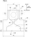
- the second curved surface portion (82) is in the shape of a curved surface having two circumferential ends that draw one phantom arc as viewed from the lower axial end thereof. Specifically, the second curved surface portion (82) has a curvature equal to that of the first curved surface portion (81). The second curved surface portion (82) is continuous with the first curved surface portion (81). A combination of these portions forms one phantom curved surface. As illustrated in FIGS. 2 and 3 , the width (W2) of the second curved surface portion (82) in the circumferential direction is greater than the width (W1) of the first curved surface portion (81) in the circumferential direction (W1 ⁇ W2). The centerline of the second curved surface portion (82) at the center thereof in the circumferential direction coincides with the centerline of the first curved surface portion at the center thereof in the circumferential direction.
- the first flow path (83) is a flow path for guiding a portion of the gas that has passed through the suction pipe (18) toward the compression mechanism (14). As illustrated in FIG. 5A , the first flow path (83) is recessed radially inward at an intermediate portion of the first curved surface portion (81) in the circumferential direction. As illustrated in FIG. 3 , the first flow path (83) has a rectangular shape as viewed in the radial direction. The first flow path (83) is provided across the first curved surface portion (81) in the axial direction. The first flow path (83) is recessed radially inward by a uniform depth (D1) at any location.
- D1 uniform depth
- the second flow path (84) is a flow path for guiding the remaining portion of the gas that has passed through the suction pipe (18) toward the motor (6). As illustrated in FIGS. 5B and 5C , the second flow path (84) is recessed radially inward at an intermediate portion of the second curved surface portion (82) in the circumferential direction. More specifically, the second flow path (84) has a tapered portion (85), a reverse tapered portion (86), and a wide portion (87). The second flow path (84) further has a narrowed portion (88) between the tapered portion (85) and the reverse tapered portion (86).
- the tapered portion (85) has a flow path cross-sectional area that decreases toward the lower axial end thereof. As illustrated in FIG. 3 , as viewed in the radial direction, the tapered portion (85) is substantially in the shape of an inverted isosceles triangle. As illustrated in FIGS. 2 and 4 , the bottom of the flow path of the tapered portion (85) has a depth that decreases gradually downward. In other words, the inner surface of the tapered portion (85) in the radial direction is inclined with respect to the axial direction so as to be positioned radially outward toward the lower end thereof.
- the reverse tapered portion (86) is provided below the tapered portion (85).
- the reverse tapered portion (86) has a flow path cross-sectional area that increases axially downward.
- the reverse tapered portion (86) is substantially in the shape of an isosceles triangle.
- the bottom of the flow path of the reverse tapered portion (86) has a uniform depth (D2) over the entire area of the reverse tapered portion (86) (D2 ⁇ D1).
- D2 uniform depth
- the inner surface of the reverse tapered portion (86) in the radial direction is parallel to the axial direction.
- the wide portion (87) is provided below the tapered portion (86) and continuously with the reverse tapered portion (86).
- the wide portion (87) has a rectangular shape as viewed in the radial direction.
- the second flow path (84) is recessed radially inward by a uniform depth (D2) at any location. That is to say, the inner surface of the wide portion (87) in the radial direction forms an arc-shaped surface continuous with the inner surface of the reverse tapered portion (86) in the radial direction.
- the narrowed portion (88) is provided at the boundary between the tapered portion (85) and the reverse tapered portion (86).
- the narrowed portion (88) forms a portion having a narrowed flow path cross-sectional area.
- the upper end of the narrowed portion (88) is connected to the lower end of the tapered portion (85), and the lower end of the narrowed portion (88) is connected to the upper end of the reverse tapered portion (86).
- the first flow path (83) has a uniform flow path cross-sectional area
- its minimum flow path cross-sectional area is the area of a region indicated by the dashed-and-double-dotted line in FIG. 5A .
- the second flow path (84) has a flow path cross-sectional area that varies in the axial direction, and its minimum flow path cross-sectional area is the area of a region (the narrowed portion) indicated by the dashed-and-double-dotted line in FIG. 5B .
- stator (61) Details of the configuration of the stator (61) according to this embodiment will be described below with reference to FIGS. 1 and 6 .
- the stator (61) has an outer peripheral surface with four core cuts at predetermined intervals (at intervals of 90° in this embodiment). Each core cut is formed from the upper end to the lower end of the stator (61) such that the outer peripheral surface of the stator is partially cut off. Each core cut of this embodiment forms a flat surface parallel to the axial direction.
- the core cuts are arranged between the outer peripheral surface of the stator (61) and the inner peripheral surface of the barrel (11) of the casing (10) to form a plurality of circulation paths extending in the top-to-bottom direction between the barrel (11) and the stator (61).
- the plurality of circulation paths allow an internal region of the casing (10) near one axial end of the motor (6) and another internal region of the casing (10) near the other axial end of the motor (6) to communicate with each other.
- a first gas flow path (91) that is one of the plurality of circulation paths is arranged at an angular position that permits connection with the suction pipe (18) (specifically, generally directly below the suction pipe (18)), and is used to direct the flow of the sucked refrigerant gas downward to form a downward flow.
- An oil discharge passage (95) that is another one of the plurality of circulation paths is arranged at an angular position that is 180° rotationally symmetrical to the first gas flow path (91), and is used to allow the lubricant that has lubricated the bearings and other components through the drive shaft (7) to flow to the oil reservoir (15).
- a guide member (57) for guiding the lubricant is arranged to extend from the above-described second gap (9) to an axially intermediate portion of the oil discharge passage (95). At least one of the second or third gas flow path that is one of the remaining two of the plurality of circulation paths is used to direct a swirl flow generated by the above-described downward flow colliding with the partition plate (26) and the rotation of the motor (6) upward to form an upward flow.
- the above-described gas guide (80) is attached such that the curved surface portions (81, 82) conform to the inner peripheral surface of the barrel (11) in a condition where the first flow path (83) faces the open end (18A) of the suction pipe (18), and in a condition where the first flow path (83) has its outlet (upper end) directed toward the compression mechanism (14) and the second flow path (84) has its outlet (lower end) directed toward the motor (6).
- Various known methods may be used for this attachment. For example, screwing, welding, soldering, or any other method may be used. As illustrated in FIG.
- the outlet of the second flow path (84) and a first open end (91A) that is the upper end of the first gas flow path (91) face each other.
- the outlet of the second flow path (84) covers the first open end (91A). That is to say, the first open end (91A) is surrounded by the outlet of the second flow path (84).
- the scroll compressor (1) includes the gas guide (80).
- the gas guide (80) has the first flow path (83) that guides a portion of the gas that has passed through the suction pipe (18) toward the compression mechanism (14), and the second flow path (84) that guides the remaining portion of the gas that passed through the suction pipe (18) toward the gas flow path (91).
- This allows a portion of the gas sucked through the suction pipe (18) to cool the motor (6) along the axial direction.
- the temperature difference between one axial end and the other axial end of the motor (6) decreases. This makes the temperatures of different portions of the motor (6) more uniform.
- This allows a temperature sensor attached to a portion of the motor (6) to accurately sense the temperature of the entire motor (6).
- a single temperature sensor can accurately sense an abnormal condition, such as an excessive increase in the temperature of the motor (6). Taking an appropriate measure based on the result of this sensing can improve the reliability of the motor (6).
- the minimum flow path cross-sectional area of the first flow path (83) is larger than the minimum flow path cross-sectional area of the second flow path (84). This allows the gas sucked through the suction pipe (18) to flow more easily toward the compression mechanism (14) than toward the motor (6). This can prevent an adverse effect caused by the gas flowing excessively toward the motor (6).
- the gas that has flowed toward the motor (6) absorbs heat from the motor (6).
- its temperature increases, and its density decreases.
- the mass of the refrigerant to be sucked by the compression mechanism (14) decreases.
- setting the minimum flow path cross-sectional area of the first flow path (83) to be larger than that of the second flow path (84) limits the flow rate of the gas flowing through the motor (6).
- this embodiment can keep the density of the gas to be sucked into the compression mechanism (14) from decreasing to keep the efficiency of the scroll compressor (1) from decreasing, and can reduce the temperature difference between the one axial end and the other axial end of the motor (6).
- the second flow path (84) of the gas guide (80) has the tapered portion (85) and the reverse tapered portion (86).
- the second flow path (84) has the narrowed portion (88) at the joint between the tapered portion (85) and the reverse tapered portion (86). This limits the amount of the refrigerant gas flowing toward the motor (6).
- Spreading the refrigerant gas that has passed through the narrowed portion (88) along the surface of the reverse tapered portion (86) lowers the velocity of flow of the refrigerant gas. As a result, the velocity of flow of the gas flowing toward the motor (6) can be lowered.
- oil reservoir (15) is closer to the lower end of the casing (10) than the motor (6) for the compression mechanism (14) is, oil loss can be prevented.
- the lubricant in the oil reservoir (15) may be splashed up by the gas ejected from the first gas flow path (91).
- the lubricant splashed up flows together with the refrigerant gas so as to be sucked into the compression mechanism (14), and flows out of the scroll compressor (1) through the discharge pipe (19) together with the refrigerant gas compressed in the compression mechanism (14).
- the gas guide (80) having the reverse tapered portion (86) reduces the velocity of flow of the gas flowing through the first gas flow path (91) to a low velocity.
- this embodiment can reduce the amount of the lubricant flowing out of the scroll compressor (1) to a small amount, thus maintaining the reliability of the scroll compressor (1).
- the outlet of the second flow path (84) of the gas guide (80) faces the first open end (91A) of the first gas flow path (91) near the gas guide. This allows the gas flowing through the second flow path (84) to flow efficiently to the first gas flow path (91).
- the outlet of the second flow path (84) overlaps with the entire first open end (91A) of the first gas flow path (91) as viewed in the axial direction of the casing (10). This can hinder the total amount of the refrigerant gas flowing through the second flow path (84) from flowing to the first gas flow path (91). That is to say, the gas that has flowed through the second flow path (84) can be kept from flowing excessively to the first gas flow path (91). This can prevent an adverse effect caused by the gas flowing excessively toward the motor (6).
- the bottom of the tapered portion (85) of the gas guide (80) is inclined radially outward toward its lower axial end.
- the plain configuration allows the minimum flow path cross-sectional area of the first flow path (83) to be larger than the minimum flow path cross-sectional area of the second flow path (84).
- the simple configuration allows the refrigerant gas sucked through the suction pipe (18) to flow more easily toward the compression mechanism (14) than toward the motor (6).
- the compressor is a scroll compressor.
- the compressor may be a rotary compressor, a screw compressor, a sliding vane compressor, or any other type of compressor.
- the axial direction of the casing (10) is directed in the top-to-bottom direction, and a so-called “vertical compressor” is used.
- the compressor may be a horizontal compressor.
- the line defining the boundary between the gas guide and each of the curved surface portions is straight. This is merely an example.
- the boundary between the gas guide and each of the curved surface portions may be curved. This may facilitate further smoothing the flow of the working fluid from the tapered portion to the narrowed portion and from the narrowed portion to the reverse tapered portion, for example.
- the core cuts of the stator (61) are each in the shape of a flat surface formed such that the outer periphery of the stator (61) is partially cut off. This is merely an example. Alternatively, the core cuts may be each in the shape of an arc formed such that the outer periphery of the stator is partially cut away.
- the present disclosure is useful for a compressor.
Landscapes
- Engineering & Computer Science (AREA)
- Mechanical Engineering (AREA)
- General Engineering & Computer Science (AREA)
- Applications Or Details Of Rotary Compressors (AREA)
- Rotary Pumps (AREA)
- Compressor (AREA)
- Structures Of Non-Positive Displacement Pumps (AREA)
Abstract
Description
- The present disclosure relates to a compressor.
- A compressor that has been known in the art includes a flow regulating member for diverting a gas sucked into a casing. A compressor of this type is described, for example, in Patent Document 1.
- The compressor of Patent Document 1 includes a closed container, an electric motor element, a compression mechanism section driven by the electric motor element, a suction pipe through which a refrigerant is sucked into the closed container, and a regulating vane that diverts the refrigerant sucked through the suction pipe. A first opening through which one of two streams of the refrigerant diverted by the regulating vane passes is formed toward the compressor section. A second opening through which the other stream passes is formed toward the electric motor element.
- The compressor of Patent Document 1 can cool the electric motor element as well as the compressor section.
- Patent Document 1:
Japanese Unexamined Patent Publication No. 2018-131910 - Unfortunately, while the refrigerant from the second opening of the regulating vane is adequately supplied to a region of the compressor of Patent Document 1 near one axial end of the electric motor element (near the compression element), the refrigerant may be inadequately supplied to a region thereof near the other axial end of the electric motor element (remote from the compression element). Thus, the region near the other axial end of the motor may be inadequately cooled.
- It is an object of the present disclosure to reduce the temperature difference between one axial end and the other axial end of a motor to improve the reliability of the motor.
- A first aspect of the present disclosure is directed to a compressor (1) including: a casing (10) having a tubular shape; a compression mechanism (14); a motor (6); a suction pipe (18); a gas flow path (91); and a gas guide (80). The compression mechanism (14) is arranged near one end of the casing (10) in the casing (10) to compress a gas. The motor (6) is arranged near another end of the casing (10) in the casing (10) to drive the compression mechanism (14). The suction pipe (18) opens between the compression mechanism (14) and the motor (6) in the casing (10). The gas flow path (91) is formed between the motor (6) and an inner peripheral surface of the casing (10), and allows an internal region of the casing (10) near one axial end of the motor (6) and another internal region of the casing (10) near another axial end of the motor (6) to communicate with each other. The gas guide (80) faces an open end (18A) of the suction pipe (18) in the casing (10), and includes a first flow path (83) and a second flow path (84). The first flow path (83) is configured to guide a portion of a gas that has passed through the suction pipe (18) toward the compression mechanism (14). The second flow path (84) is configured to guide a remaining portion of the gas that has passed through the suction pipe (18) toward the gas flow path (91).
- According to the first aspect, a portion of the gas sucked through the suction pipe (18) is guided to the gas flow path (91) by the second flow path (84) of the gas guide (80), and is supplied through the gas flow path (91) toward the another axial end of the motor (6). A portion of the motor (6) near the another axial end is cooled by the gas that has passed through the gas flow path (91). As a result, the temperature difference between the one axial end and the another axial end of the motor (6) decreases, thus improving the reliability of the motor (6).
- A second aspect of the present disclosure is an embodiment of the first aspect. In the second aspect, a minimum flow path cross-sectional area of the first flow path (83) is larger than a minimum flow path cross-sectional area of the second flow path (84).
- The second aspect allows the gas sucked through the suction pipe (18) to flow more easily toward the compression mechanism (14) than toward the motor (6). This can prevent an adverse effect caused by the gas flowing excessively toward the motor (6).
- A third aspect of the present disclosure is an embodiment of the first or second aspect. In the third aspect, the second flow path (84) includes a tapered portion (85) and a reverse tapered portion (86). The tapered portion (85) has a flow path cross-sectional area that decreases toward an outlet of the second flow path (84). The reverse tapered portion (86) is closer to the outlet of the second flow path (84) than the tapered portion (85) is. The reverse tapered portion (86) has a flow path cross-sectional area that increases toward the outlet of the second flow path (84).
- According to the third aspect, the second flow path (84) has the narrowed portion (88) at the joint between the tapered portion (85) and the reverse tapered portion (86). This limits the amount of the gas flowing toward the motor (6). Spreading the gas that has passed through the narrowed portion (88) along the surface of the gas guide (80) lowers the velocity of flow of the gas. As a result, the velocity of flow of the gas flowing toward the motor (6) can be lowered. For example, if an oil reservoir is closer to the another end of the casing (10) than the motor (6) of the compressor (1) is, oil in the oil reservoir can be prevented from being scattered by the gas flow.
- A fourth aspect of the present disclosure is an embodiment of any one of the first to third aspects. In the fourth aspect, an outlet of the second flow path (84) faces a first open end (91A) of the gas flow path (91) near the gas guide (80).
- The fourth aspect allows the gas flowing through the second flow path (84) to flow efficiently to the gas flow path (91).
- A fifth aspect of the present disclosure is an embodiment of the fourth aspect. In the fifth aspect, the outlet of the second flow path (84) overlaps with an entirety of the first open end (91A) of the gas flow path (91) as viewed in an axial direction of the casing (10).
- According to the fifth aspect, the gas that has flowed through the second flow path (84) can be kept from flowing excessively to the gas flow path (91). This can prevent an adverse effect caused by the gas flowing excessively toward the motor (6).
-
-
FIG. 1 is a longitudinal sectional view of a scroll compressor according to an embodiment of the present disclosure. -
FIG. 2 is a perspective view of a gas guide. -
FIG. 3 illustrates the gas guide as viewed from the outside in a radial direction. -
FIG. 4 is a longitudinal sectional view of the gas guide. -
FIG. 5A is a cross-sectional view taken along line VA-VA shown inFIG. 3 . -
FIG. 5B is a cross-sectional view taken along line VB-VB shown inFIG. 3 . -
FIG. 5C is a cross-sectional view taken along line VC-VC shown inFIG. 3 . -
FIG. 6 illustrates the layout relationship between an outlet of a second flow path of the gas guide and a first gas flow path as viewed in an axial direction. - An embodiment of the present disclosure will be described below with reference to the accompanying drawings. The following embodiment is a merely preferred example in nature, and is not intended to limit the scope, applications, or use of the invention.
- A scroll compressor (1) according to an embodiment of the present disclosure is connected to a refrigerant circuit through which a refrigerant gas circulates to perform a refrigeration cycle, and compresses the refrigerant gas serving as a working fluid. The scroll compressor (1) is used, for example, in an air conditioner or a refrigeration apparatus.
-
FIG. 1 is a longitudinal sectional view of the scroll compressor (1). As illustrated inFIG. 1 , the scroll compressor (1) is a hermetic compressor, and mainly includes a casing (10), a compression mechanism (14), a motor (6), a drive shaft (7), a lower bearing (21), a partition plate (26), an suction pipe (18), and a discharge pipe (19). - The casing (10) is a closed container with both ends closed. The casing (10) has a vertically long cylindrical shape with an axis parallel to the top-to-bottom direction. The casing (10) includes a barrel (11), an upper end plate (12), and a lower end plate (13). The barrel (11) has a cylindrical shape with an axis oriented in the top-to-bottom direction. The upper end plate (12) has a convex surface protruding upward in a bowl shape. The upper end plate (12) is airtightly welded to, and integrally bonded to, an upper end portion of the barrel (11). The lower end plate (13) has a convex surface protruding downward in a bowl shape. The lower end plate (13) is airtightly welded to, and integrally bonded to, a lower end portion of the barrel (11).
- The compression mechanism (14), the motor (6), the lower bearing (21), and the partition plate (26) are arranged in the casing (10). The compression mechanism (14) is arranged near an upper end of the interior of the casing (10). The motor (6) is arranged near a lower end of the interior of the casing (10). The lower bearing (21) is arranged closer to the lower end of the interior of the casing (10) than the motor (6) is. The partition plate (26) is arranged radially outside the lower bearing (21) in the casing (10). The partition plate (26) is arranged below the motor (6) in the casing (10). The drive shaft (7) is housed in the casing (10) such that the direction of its axis corresponds to the direction of the axis of the barrel (11).
- As will be described in detail later, the compression mechanism (14) compresses the refrigerant gas introduced into the casing (10). The motor (6) drives the compression mechanism (14). Specifically, the motor (6) rotates the drive shaft (7), which rotates a movable scroll (5), described later, to drive the compression mechanism (14).
- The casing (10) has, at its bottom, an oil reservoir (15) for storing lubricant. The partition plate (26) covers the lubricant stored at the bottom of the casing (10) from above.
- The suction pipe (18) is provided for the barrel (11) of the casing (10). The suction pipe (18) introduces the refrigerant gas in the refrigerant circuit into the casing (10). The suction pipe (18) opens between the compression mechanism (14) and the motor (6) in the casing (10). The suction pipe (18) connects the inside and outside of the barrel (11) together.
- The discharge pipe (19) is provided at the top of the casing (10). The discharge pipe (19) delivers the refrigerant gas compressed by the compression mechanism (14) to the refrigerant circuit. The discharge pipe (19) connects the inside and outside of the upper end plate (12) together.
- The drive shaft (7) has a main shaft portion (71), an eccentric portion (72), and a counterweight portion (73). The eccentric portion (72) is relatively shorter than the main shaft portion (71). The eccentric portion is provided to extend axially from the upper end surface of the main shaft portion (71). The eccentric portion (72) has an axis decentered by a predetermined distance with respect to the axis of the main shaft portion (71). The counterweight portion (73) is provided radially outside the main shaft portion (71) so as to be dynamically balanced with the eccentric portion (72), the movable scroll (5), described later, or any other component. The drive shaft (7) has therein an oil supply channel (74) extending from the upper end to the lower end thereof. A lower end portion of the drive shaft (7) is immersed in oil in the oil reservoir (15).
- The motor (6) is arranged below the compression mechanism (14) in the casing (10). The motor (6) includes a stator (61) and a rotor (62). The stator (61) is fixed to the inner peripheral surface of the barrel (11) of the casing (10) by shrink fitting or any other process. The rotor (62) is arranged radially inside the stator (61), and is fixed to the main shaft portion (71) of the drive shaft (7). The rotor (62) is arranged substantially coaxially with the main shaft portion (71). The rotor (62) is connected to the compression mechanism (14) with the drive shaft (7) interposed therebetween.
- The partition plate (26) is fixed to the inner peripheral surface of the barrel (11) of the casing (10) at a location between the motor (6) and the oil reservoir (15). The partition plate (26) is generally ring-shaped as viewed in the axial direction. The lower bearing (21) is fixed in a through hole of a central portion of the partition plate (26) using a fastening means, such as a screw. The lower bearing (21) is generally cylindrical, and is arranged substantially coaxially with the partition plate (26). The lower bearing (21) rotatably supports the lower end portion of the drive shaft (7).
- The compression mechanism (14) includes a housing (3), a fixed scroll (4), and the movable scroll (5). The housing (3) is fixed to an upper portion of the barrel (11) of the casing (10). The fixed scroll (4) is fixed to the upper end portion of the barrel (11) of the housing (3). The movable scroll (5) is arranged between the fixed scroll (4) and the housing (3). The housing (3) has a central portion recessed from its upper end toward its lower end in a dish shape. The housing (3) has a ring-shaped portion (31) near its outer periphery and a recessed portion (32) near its inner periphery.
- A first gap (8) extending axially is formed between the outer peripheral surface of the housing (3) and the inner peripheral surface of the barrel (11) of the casing (10) at the angular position where the suction pipe (18) is arranged. The first gap (8) allows a space above the housing (3) and a space below the housing (3) to communicate with each other. A second gap (9) extending axially is formed between the outer peripheral surface of the housing (3) and the inner peripheral surface of the barrel (11) of the casing (10) at the angular position that is 180° rotationally symmetrical to the first gap (8). The gap (9) allows the space above the housing (3) and the space below the housing (3) to communicate with each other. If no attention is paid to these gaps (8, 9), the housing (3) partitions the internal space of the casing (10) into an upper space (16) and a lower space (17).
- The housing (3) has a through hole (33) passing therethrough from the bottom of the recessed portion (32) to the lower end thereof. A bearing metal (not shown) is inserted into the through hole (33). The drive shaft (7) is inserted into the bearing metal. As can be seen, the housing (3) constitutes an upper bearing that rotatably supports an upper end portion of the drive shaft (7). The housing (3) has an oil discharge passage (38) extending from the recessed portion (32) toward its outer peripheral surface and opening to the second gap (9).
- The fixed scroll (4) includes a fixed end plate (41), a fixed wrap (42), and an outer peripheral wall (43). The fixed wrap (42) is in the shape of a spiral wall that draws an involute curve, and protrudes from the lower end face of the fixed end plate (41). The fixed scroll (4) is fixed to the barrel (11) of the casing (10).
- The movable scroll (5) includes a movable end plate (51), a movable wrap (52), and a boss (53). The movable end plate (51) has a substantially circular flat plate shape as viewed in the axial direction. The movable wrap (52) is in the shape of a spiral wall that draws an involute curve, and protrudes from the upper end face of the movable end plate (51). The boss (53) is in a cylindrical shape extending axially, and is arranged at a center portion of the lower end face of the movable end plate (51).
- The movable wrap (52) of the movable scroll (5) meshes with the fixed wrap (42) of the fixed scroll (4). The compression mechanism (14) has a compression chamber (50) surrounded by the fixed end plate (41) and the fixed wrap (42) of the fixed scroll (4) and the movable end plate (51) and the movable wrap (52) of the movable scroll (5).
- A discharge port (44) passing through the fixed end plate (41) is open at the center of the fixed end plate (41) of the fixed scroll (4). A high-pressure chamber (45) is provided in the upper end face of the fixed end plate (41). The discharge port (44) is open to the high-pressure chamber (45). The high-pressure chamber (45) constitutes a high-pressure space. The high-pressure chamber (45) communicates with a space inside the upper end plate (12).
- An Oldham coupling (55) is engaged in a keyway formed on the lower end face of the movable end plate (51) of the movable scroll (5) and a keyway formed on the ring-shaped portion (31) of the housing (3), and regulates the rotation of the movable scroll (5) on its own axis.
- In the compression mechanism (14) having a configuration similar to that described above, energizing the motor (6) allows the drive shaft (7) to rotate the movable scroll (5). The rotation of the movable scroll (5) on its own axis is regulated by the Oldham coupling (55). Thus, the movable scroll (5) merely revolves without rotating on its own axis. The revolution of the movable scroll (5) causes the volume between the wraps (42, 52) to contract toward the center, thus compressing the refrigerant gas moving toward the center. The compressed refrigerant gas is supplied through the discharge port (44), the high-pressure chamber (45), and the discharge pipe (19) to the refrigerant circuit.
- The scroll compressor (1) of this embodiment further includes a gas guide (80). The configuration of the gas guide (80) will be described in detail below with reference to
FIGS. 1 to 5C . In the following description, directions will be defined using the axial direction, radial direction, and circumferential direction of the scroll compressor (1), based on the orientation of the gas guide (80) attached to the scroll compressor (1). - The gas guide (80) is a member for diverting (regulating the flow of) the refrigerant gas sucked from the suction pipe (18). As illustrated in
FIGS. 1 and3 , the gas guide (80) is arranged to face an open end (18A) of the suction pipe (18) in the casing (10). The gas guide (80) includes a first curved surface portion (81), a second curved surface portion (82), a first flow path (83), and a second flow path (84). - The first curved surface portion (81) is in the shape of a curved surface having two circumferential ends that draw one phantom arc as viewed from the upper axial end thereof. Specifically, the first curved surface portion (81) has a curvature along the inner peripheral surface of the barrel (11) of the casing (10).
- The second curved surface portion (82) is in the shape of a curved surface having two circumferential ends that draw one phantom arc as viewed from the lower axial end thereof. Specifically, the second curved surface portion (82) has a curvature equal to that of the first curved surface portion (81). The second curved surface portion (82) is continuous with the first curved surface portion (81). A combination of these portions forms one phantom curved surface. As illustrated in
FIGS. 2 and3 , the width (W2) of the second curved surface portion (82) in the circumferential direction is greater than the width (W1) of the first curved surface portion (81) in the circumferential direction (W1 < W2). The centerline of the second curved surface portion (82) at the center thereof in the circumferential direction coincides with the centerline of the first curved surface portion at the center thereof in the circumferential direction. - The first flow path (83) is a flow path for guiding a portion of the gas that has passed through the suction pipe (18) toward the compression mechanism (14). As illustrated in
FIG. 5A , the first flow path (83) is recessed radially inward at an intermediate portion of the first curved surface portion (81) in the circumferential direction. As illustrated inFIG. 3 , the first flow path (83) has a rectangular shape as viewed in the radial direction. The first flow path (83) is provided across the first curved surface portion (81) in the axial direction. The first flow path (83) is recessed radially inward by a uniform depth (D1) at any location. When the gas guide (80) is attached to the scroll compressor (1), a central portion of the first flow path (83) faces the open end (18A) of the suction pipe (18) as viewed in the radial direction. - The second flow path (84) is a flow path for guiding the remaining portion of the gas that has passed through the suction pipe (18) toward the motor (6). As illustrated in
FIGS. 5B and 5C , the second flow path (84) is recessed radially inward at an intermediate portion of the second curved surface portion (82) in the circumferential direction. More specifically, the second flow path (84) has a tapered portion (85), a reverse tapered portion (86), and a wide portion (87). The second flow path (84) further has a narrowed portion (88) between the tapered portion (85) and the reverse tapered portion (86). - The tapered portion (85) has a flow path cross-sectional area that decreases toward the lower axial end thereof. As illustrated in
FIG. 3 , as viewed in the radial direction, the tapered portion (85) is substantially in the shape of an inverted isosceles triangle. As illustrated inFIGS. 2 and4 , the bottom of the flow path of the tapered portion (85) has a depth that decreases gradually downward. In other words, the inner surface of the tapered portion (85) in the radial direction is inclined with respect to the axial direction so as to be positioned radially outward toward the lower end thereof. - As illustrated in
FIG. 3 , the reverse tapered portion (86) is provided below the tapered portion (85). The reverse tapered portion (86) has a flow path cross-sectional area that increases axially downward. As viewed in the radial direction, the reverse tapered portion (86) is substantially in the shape of an isosceles triangle. As illustrated inFIG. 4 , the bottom of the flow path of the reverse tapered portion (86) has a uniform depth (D2) over the entire area of the reverse tapered portion (86) (D2 < D1). In other words, the inner surface of the reverse tapered portion (86) in the radial direction is parallel to the axial direction. - As illustrated in
FIG. 3 , the wide portion (87) is provided below the tapered portion (86) and continuously with the reverse tapered portion (86). The wide portion (87) has a rectangular shape as viewed in the radial direction. As illustrated inFIG. 4 , the second flow path (84) is recessed radially inward by a uniform depth (D2) at any location. That is to say, the inner surface of the wide portion (87) in the radial direction forms an arc-shaped surface continuous with the inner surface of the reverse tapered portion (86) in the radial direction. - As illustrated in
FIG. 3 , the narrowed portion (88) is provided at the boundary between the tapered portion (85) and the reverse tapered portion (86). The narrowed portion (88) forms a portion having a narrowed flow path cross-sectional area. The upper end of the narrowed portion (88) is connected to the lower end of the tapered portion (85), and the lower end of the narrowed portion (88) is connected to the upper end of the reverse tapered portion (86). - Since the first flow path (83) has a uniform flow path cross-sectional area, its minimum flow path cross-sectional area is the area of a region indicated by the dashed-and-double-dotted line in
FIG. 5A . Meanwhile, the second flow path (84) has a flow path cross-sectional area that varies in the axial direction, and its minimum flow path cross-sectional area is the area of a region (the narrowed portion) indicated by the dashed-and-double-dotted line inFIG. 5B . - Details of the configuration of the stator (61) according to this embodiment will be described below with reference to
FIGS. 1 and6 . - The stator (61) according to this embodiment has an outer peripheral surface with four core cuts at predetermined intervals (at intervals of 90° in this embodiment). Each core cut is formed from the upper end to the lower end of the stator (61) such that the outer peripheral surface of the stator is partially cut off. Each core cut of this embodiment forms a flat surface parallel to the axial direction. The core cuts are arranged between the outer peripheral surface of the stator (61) and the inner peripheral surface of the barrel (11) of the casing (10) to form a plurality of circulation paths extending in the top-to-bottom direction between the barrel (11) and the stator (61). The plurality of circulation paths allow an internal region of the casing (10) near one axial end of the motor (6) and another internal region of the casing (10) near the other axial end of the motor (6) to communicate with each other.
- A first gas flow path (91) that is one of the plurality of circulation paths is arranged at an angular position that permits connection with the suction pipe (18) (specifically, generally directly below the suction pipe (18)), and is used to direct the flow of the sucked refrigerant gas downward to form a downward flow. An oil discharge passage (95) that is another one of the plurality of circulation paths is arranged at an angular position that is 180° rotationally symmetrical to the first gas flow path (91), and is used to allow the lubricant that has lubricated the bearings and other components through the drive shaft (7) to flow to the oil reservoir (15). In this embodiment, a guide member (57) for guiding the lubricant is arranged to extend from the above-described second gap (9) to an axially intermediate portion of the oil discharge passage (95). At least one of the second or third gas flow path that is one of the remaining two of the plurality of circulation paths is used to direct a swirl flow generated by the above-described downward flow colliding with the partition plate (26) and the rotation of the motor (6) upward to form an upward flow.
- The above-described gas guide (80) is attached such that the curved surface portions (81, 82) conform to the inner peripheral surface of the barrel (11) in a condition where the first flow path (83) faces the open end (18A) of the suction pipe (18), and in a condition where the first flow path (83) has its outlet (upper end) directed toward the compression mechanism (14) and the second flow path (84) has its outlet (lower end) directed toward the motor (6). Various known methods may be used for this attachment. For example, screwing, welding, soldering, or any other method may be used. As illustrated in
FIG. 6 , when the gas guide (80) is attached to the scroll compressor (1), the outlet of the second flow path (84) and a first open end (91A) that is the upper end of the first gas flow path (91) face each other. As viewed in the axial direction, the outlet of the second flow path (84) covers the first open end (91A). That is to say, the first open end (91A) is surrounded by the outlet of the second flow path (84). - As indicated above, the scroll compressor (1) according to this embodiment includes the gas guide (80). The gas guide (80) has the first flow path (83) that guides a portion of the gas that has passed through the suction pipe (18) toward the compression mechanism (14), and the second flow path (84) that guides the remaining portion of the gas that passed through the suction pipe (18) toward the gas flow path (91). This allows a portion of the gas sucked through the suction pipe (18) to cool the motor (6) along the axial direction. As a result, the temperature difference between one axial end and the other axial end of the motor (6) decreases. This makes the temperatures of different portions of the motor (6) more uniform. This allows a temperature sensor attached to a portion of the motor (6) to accurately sense the temperature of the entire motor (6). Moreover, a single temperature sensor can accurately sense an abnormal condition, such as an excessive increase in the temperature of the motor (6). Taking an appropriate measure based on the result of this sensing can improve the reliability of the motor (6).
- As illustrated in
FIGS. 5A and 5B , the minimum flow path cross-sectional area of the first flow path (83) is larger than the minimum flow path cross-sectional area of the second flow path (84). This allows the gas sucked through the suction pipe (18) to flow more easily toward the compression mechanism (14) than toward the motor (6). This can prevent an adverse effect caused by the gas flowing excessively toward the motor (6). - Specifically, the gas that has flowed toward the motor (6) absorbs heat from the motor (6). Thus, its temperature increases, and its density decreases. For this reason, the higher the flow rate of the gas flowing toward the motor (6) is, the lower the density of the gas to be sucked into the compression mechanism (14) is. As a result, every time the movable scroll (5) makes one revolution, the mass of the refrigerant to be sucked by the compression mechanism (14) decreases. To address this problem, in this embodiment, setting the minimum flow path cross-sectional area of the first flow path (83) to be larger than that of the second flow path (84) limits the flow rate of the gas flowing through the motor (6). Thus, this embodiment can keep the density of the gas to be sucked into the compression mechanism (14) from decreasing to keep the efficiency of the scroll compressor (1) from decreasing, and can reduce the temperature difference between the one axial end and the other axial end of the motor (6).
- In the scroll compressor (1) according to this embodiment, the second flow path (84) of the gas guide (80) has the tapered portion (85) and the reverse tapered portion (86). Thus, the second flow path (84) has the narrowed portion (88) at the joint between the tapered portion (85) and the reverse tapered portion (86). This limits the amount of the refrigerant gas flowing toward the motor (6). Spreading the refrigerant gas that has passed through the narrowed portion (88) along the surface of the reverse tapered portion (86) lowers the velocity of flow of the refrigerant gas. As a result, the velocity of flow of the gas flowing toward the motor (6) can be lowered. Just like this embodiment, for example, if the oil reservoir (15) is closer to the lower end of the casing (10) than the motor (6) for the compression mechanism (14) is, oil loss can be prevented.
- Specifically, if the velocity of flow of the refrigerant gas guided by the gas guide (80) and flowing downward through the first gas flow path (91) is excessively high, the lubricant in the oil reservoir (15) may be splashed up by the gas ejected from the first gas flow path (91). The lubricant splashed up flows together with the refrigerant gas so as to be sucked into the compression mechanism (14), and flows out of the scroll compressor (1) through the discharge pipe (19) together with the refrigerant gas compressed in the compression mechanism (14). Thus, an increase in the amount of the lubricant splashed up by the refrigerant gas that has passed through the first gas flow path (91) triggers an increase in the amount of the lubricant flowing out of the scroll compressor (1), resulting in a decrease in the amount of the lubricant in the oil reservoir (15). As a result, the compression mechanism (14) or any other component may be damaged due to poor lubrication. To address this problem, in this embodiment, the gas guide (80) having the reverse tapered portion (86) reduces the velocity of flow of the gas flowing through the first gas flow path (91) to a low velocity. Thus, this embodiment can reduce the amount of the lubricant flowing out of the scroll compressor (1) to a small amount, thus maintaining the reliability of the scroll compressor (1).
- In the scroll compressor (1) according to this embodiment, the outlet of the second flow path (84) of the gas guide (80) faces the first open end (91A) of the first gas flow path (91) near the gas guide. This allows the gas flowing through the second flow path (84) to flow efficiently to the first gas flow path (91).
- In the scroll compressor (1) according to this embodiment, the outlet of the second flow path (84) overlaps with the entire first open end (91A) of the first gas flow path (91) as viewed in the axial direction of the casing (10). This can hinder the total amount of the refrigerant gas flowing through the second flow path (84) from flowing to the first gas flow path (91). That is to say, the gas that has flowed through the second flow path (84) can be kept from flowing excessively to the first gas flow path (91). This can prevent an adverse effect caused by the gas flowing excessively toward the motor (6).
- In the scroll compressor (1) according to this embodiment, the bottom of the tapered portion (85) of the gas guide (80) is inclined radially outward toward its lower axial end. As can be seen, the plain configuration allows the minimum flow path cross-sectional area of the first flow path (83) to be larger than the minimum flow path cross-sectional area of the second flow path (84). As a result, the simple configuration allows the refrigerant gas sucked through the suction pipe (18) to flow more easily toward the compression mechanism (14) than toward the motor (6).
- While the exemplary embodiment of the present invention has been described above, the present invention is not limited to the above embodiment.
- In the above embodiment, the compressor is a scroll compressor. This is merely an example. Alternatively, the compressor may be a rotary compressor, a screw compressor, a sliding vane compressor, or any other type of compressor.
- In the above embodiment, the axial direction of the casing (10) is directed in the top-to-bottom direction, and a so-called "vertical compressor" is used. This is merely an example. Alternatively, the compressor may be a horizontal compressor.
- In the above embodiment, the line defining the boundary between the gas guide and each of the curved surface portions is straight. This is merely an example. Alternatively, the boundary between the gas guide and each of the curved surface portions may be curved. This may facilitate further smoothing the flow of the working fluid from the tapered portion to the narrowed portion and from the narrowed portion to the reverse tapered portion, for example.
- In the above embodiment, the core cuts of the stator (61) are each in the shape of a flat surface formed such that the outer periphery of the stator (61) is partially cut off. This is merely an example. Alternatively, the core cuts may be each in the shape of an arc formed such that the outer periphery of the stator is partially cut away.
- The elements described in the above embodiments and variations may be combined as appropriate without any contradictions.
- The present disclosure is useful for a compressor.
-
- 1
- Scroll Compressor (Compressor)
- 3
- Housing
- 4
- Fixed Scroll
- 5
- Movable Scroll
- 6
- Motor
- 7
- Drive Shaft
- 8
- First Gap
- 9
- Second Gap
- 10
- Casing
- 11
- Barrel
- 14
- Compression Mechanism
- 18
- Suction Pipe
- 19
- Discharge Pipe
- 38
- Oil Discharge Passage
- 41
- Fixed End Plate
- 42
- Fixed Wrap
- 44
- Discharge Port
- 45
- High-Pressure Chamber
- 50
- Compression Chamber
- 51
- Movable End Plate
- 52
- Movable Wrap
- 53
- Boss
- 57
- Guide Member
- 61
- Stator
- 62
- Rotor
- 71
- Shaft Portion
- 72
- Eccentric Portion
- 73
- Counterweight Portion
- 74
- Oil Supply Channel
- 80
- Gas Guide
- 81
- First Curved Surface Portion
- 82
- Second Curved Surface Portion
- 83
- First Flow Path
- 84
- Second Flow Path
- 85
- Tapered Portion
- 86
- Reverse Tapered Portion
- 87
- Wide Portion
- 88
- Narrowed Portion
- 91
- First Gas Flow Path
- 91A
- First Open End
- 95
- Oil Discharge Passage
Claims (5)
- A compressor (1) comprising:a casing (10) having a tubular shape;a compression mechanism (14) arranged near one end of the casing (10) in the casing (10) to compress a gas;a motor (6) arranged near another end of the casing (10) in the casing (10) to drive the compression mechanism (14);a suction pipe (18) opening between the compression mechanism (14) and the motor (6) in the casing (10);a gas flow path (91) formed between the motor (6) and an inner peripheral surface of the casing (10) and allowing an internal region of the casing (10) near one axial end of the motor (6) and another internal region of the casing (10) near another axial end of the motor (6) to communicate with each other; anda gas guide (80) facing an open end (18A) of the suction pipe (18) in the casing (10),the gas guide (80) including:a first flow path (83) configured to guide a portion of a gas that has passed through the suction pipe (18) toward the compression mechanism (14); anda second flow path (84) configured to guide a remaining portion of the gas that has passed through the suction pipe (18) toward the gas flow path (91).
- The compressor (1) of claim 1, wherein
a minimum flow path cross-sectional area of the first flow path (83) is larger than a minimum flow path cross-sectional area of the second flow path (84). - The compressor (1) of claim 1 or 2, wherein
the second flow path (84) includes:a tapered portion (85) having a flow path cross-sectional area that decreases toward an outlet of the second flow path (84); anda reverse tapered portion (86) being closer to the outlet of the second flow path (84) than the tapered portion (85) is, the reverse tapered portion (86) having a flow path cross-sectional area that increases toward the outlet of the second flow path (84). - The compressor (1) of any one of claims 1 to 3, wherein
an outlet of the second flow path (84) faces a first open end (91A) of the gas flow path (91) near the gas guide (80). - The compressor (1) of claim 4, wherein
the outlet of the second flow path (84) overlaps with an entirety of the first open end (91A) of the gas flow path (91) as viewed in an axial direction of the casing (10).
Applications Claiming Priority (2)
| Application Number | Priority Date | Filing Date | Title |
|---|---|---|---|
| JP2020153506A JP7037093B1 (en) | 2020-09-14 | 2020-09-14 | Compressor |
| PCT/JP2021/030744 WO2022054551A1 (en) | 2020-09-14 | 2021-08-23 | Compressor |
Publications (3)
| Publication Number | Publication Date |
|---|---|
| EP4194696A1 true EP4194696A1 (en) | 2023-06-14 |
| EP4194696A4 EP4194696A4 (en) | 2024-01-17 |
| EP4194696B1 EP4194696B1 (en) | 2025-02-12 |
Family
ID=80631557
Family Applications (1)
| Application Number | Title | Priority Date | Filing Date |
|---|---|---|---|
| EP21866511.5A Active EP4194696B1 (en) | 2020-09-14 | 2021-08-23 | Compressor |
Country Status (6)
| Country | Link |
|---|---|
| US (1) | US12196208B2 (en) |
| EP (1) | EP4194696B1 (en) |
| JP (1) | JP7037093B1 (en) |
| CN (1) | CN116075637B (en) |
| ES (1) | ES3014536T3 (en) |
| WO (1) | WO2022054551A1 (en) |
Family Cites Families (10)
| Publication number | Priority date | Publication date | Assignee | Title |
|---|---|---|---|---|
| JPH05180180A (en) * | 1992-01-07 | 1993-07-20 | Mitsubishi Electric Corp | Horizontal scroll compressor |
| US5240391A (en) * | 1992-05-21 | 1993-08-31 | Carrier Corporation | Compressor suction inlet duct |
| US5366352A (en) * | 1993-12-13 | 1994-11-22 | Deblois Raymond L | Thermostatic compressor suction inlet duct valve |
| JP2001099080A (en) | 1999-09-29 | 2001-04-10 | Mitsubishi Heavy Ind Ltd | Hermetic scroll compressor |
| JP2004218536A (en) | 2003-01-15 | 2004-08-05 | Mitsubishi Heavy Ind Ltd | Electric compressor |
| CN101713404A (en) * | 2008-10-06 | 2010-05-26 | 乐金电子(天津)电器有限公司 | Gas-liquid separation device for turbine compressor |
| JP6083173B2 (en) | 2012-09-27 | 2017-02-22 | 株式会社富士通ゼネラル | AIR CONDITIONER AND COMPRESSOR USED FOR THE SAME |
| JP2015098785A (en) * | 2013-11-18 | 2015-05-28 | ダイキン工業株式会社 | Scroll compressor |
| JP2017180175A (en) | 2016-03-29 | 2017-10-05 | 三菱重工業株式会社 | Compressor |
| JP2018131910A (en) | 2017-02-13 | 2018-08-23 | パナソニックIpマネジメント株式会社 | Scroll compressor |
-
2020
- 2020-09-14 JP JP2020153506A patent/JP7037093B1/en active Active
-
2021
- 2021-08-23 ES ES21866511T patent/ES3014536T3/en active Active
- 2021-08-23 EP EP21866511.5A patent/EP4194696B1/en active Active
- 2021-08-23 CN CN202180061717.5A patent/CN116075637B/en active Active
- 2021-08-23 WO PCT/JP2021/030744 patent/WO2022054551A1/en not_active Ceased
-
2023
- 2023-03-13 US US18/182,685 patent/US12196208B2/en active Active
Also Published As
| Publication number | Publication date |
|---|---|
| JP7037093B1 (en) | 2022-03-16 |
| ES3014536T3 (en) | 2025-04-23 |
| EP4194696A4 (en) | 2024-01-17 |
| EP4194696B1 (en) | 2025-02-12 |
| US12196208B2 (en) | 2025-01-14 |
| CN116075637B (en) | 2026-03-27 |
| CN116075637A (en) | 2023-05-05 |
| WO2022054551A1 (en) | 2022-03-17 |
| US20230213035A1 (en) | 2023-07-06 |
| JP2022047621A (en) | 2022-03-25 |
Similar Documents
| Publication | Publication Date | Title |
|---|---|---|
| CN112483388B (en) | Co-rotary compressor | |
| RU2600206C1 (en) | Scroll compressor | |
| US12000400B2 (en) | Compressor | |
| KR19990044128A (en) | Scroll compressor | |
| EP3076019A1 (en) | Scroll compressor | |
| EP2103808B1 (en) | Scroll compressor | |
| CN206770215U (en) | Screw compressor | |
| US11609029B2 (en) | Oil return flow path for a compressor | |
| US10605244B2 (en) | Scroll compressor provided with an orbiting guiding portion for improving the filling of the compression chambers | |
| EP4194696B1 (en) | Compressor | |
| CN114222861B (en) | Scroll compressor having a rotor with a rotor shaft having a rotor shaft with a | |
| JP2020029799A (en) | Displacement compressor | |
| JP7143128B2 (en) | compressor | |
| JP6134906B2 (en) | Compressor | |
| WO2016074817A1 (en) | A scroll compressor including an oldham coupling lubrification system | |
| JP2009167983A (en) | Scroll compressor | |
| JP7742582B2 (en) | Hermetic electric compressor | |
| WO2020170886A1 (en) | Hermetically sealed compressor | |
| JP2010084707A (en) | Compressor | |
| KR20190000687A (en) | Compressor having enhaced lubrication structre | |
| JP2005163637A (en) | Scroll compressor | |
| JP2022047620A (en) | Compressor | |
| WO2015092571A1 (en) | Scroll compressor | |
| JPWO2013172002A1 (en) | Compressor |
Legal Events
| Date | Code | Title | Description |
|---|---|---|---|
| STAA | Information on the status of an ep patent application or granted ep patent |
Free format text: STATUS: THE INTERNATIONAL PUBLICATION HAS BEEN MADE |
|
| PUAI | Public reference made under article 153(3) epc to a published international application that has entered the european phase |
Free format text: ORIGINAL CODE: 0009012 |
|
| STAA | Information on the status of an ep patent application or granted ep patent |
Free format text: STATUS: REQUEST FOR EXAMINATION WAS MADE |
|
| 17P | Request for examination filed |
Effective date: 20230309 |
|
| AK | Designated contracting states |
Kind code of ref document: A1 Designated state(s): AL AT BE BG CH CY CZ DE DK EE ES FI FR GB GR HR HU IE IS IT LI LT LU LV MC MK MT NL NO PL PT RO RS SE SI SK SM TR |
|
| REG | Reference to a national code |
Ref country code: DE Ref legal event code: R079 Ipc: F04C0018020000 Ref country code: DE Ref legal event code: R079 Ref document number: 602021026169 Country of ref document: DE Free format text: PREVIOUS MAIN CLASS: F04B0039060000 Ipc: F04C0018020000 |
|
| DAV | Request for validation of the european patent (deleted) | ||
| DAX | Request for extension of the european patent (deleted) | ||
| P01 | Opt-out of the competence of the unified patent court (upc) registered |
Effective date: 20231201 |
|
| A4 | Supplementary search report drawn up and despatched |
Effective date: 20231214 |
|
| RIC1 | Information provided on ipc code assigned before grant |
Ipc: F04B 39/12 20060101ALI20231208BHEP Ipc: F04B 39/06 20060101ALI20231208BHEP Ipc: F04B 35/04 20060101ALI20231208BHEP Ipc: F04C 29/12 20060101ALI20231208BHEP Ipc: F04C 29/04 20060101ALI20231208BHEP Ipc: F04C 29/02 20060101ALI20231208BHEP Ipc: F04C 23/00 20060101ALI20231208BHEP Ipc: F04C 18/02 20060101AFI20231208BHEP |
|
| GRAP | Despatch of communication of intention to grant a patent |
Free format text: ORIGINAL CODE: EPIDOSNIGR1 |
|
| STAA | Information on the status of an ep patent application or granted ep patent |
Free format text: STATUS: GRANT OF PATENT IS INTENDED |
|
| INTG | Intention to grant announced |
Effective date: 20241021 |
|
| GRAS | Grant fee paid |
Free format text: ORIGINAL CODE: EPIDOSNIGR3 |
|
| GRAA | (expected) grant |
Free format text: ORIGINAL CODE: 0009210 |
|
| STAA | Information on the status of an ep patent application or granted ep patent |
Free format text: STATUS: THE PATENT HAS BEEN GRANTED |
|
| AK | Designated contracting states |
Kind code of ref document: B1 Designated state(s): AL AT BE BG CH CY CZ DE DK EE ES FI FR GB GR HR HU IE IS IT LI LT LU LV MC MK MT NL NO PL PT RO RS SE SI SK SM TR |
|
| REG | Reference to a national code |
Ref country code: GB Ref legal event code: FG4D |
|
| REG | Reference to a national code |
Ref country code: CH Ref legal event code: EP |
|
| REG | Reference to a national code |
Ref country code: DE Ref legal event code: R096 Ref document number: 602021026169 Country of ref document: DE |
|
| REG | Reference to a national code |
Ref country code: IE Ref legal event code: FG4D |
|
| REG | Reference to a national code |
Ref country code: ES Ref legal event code: FG2A Ref document number: 3014536 Country of ref document: ES Kind code of ref document: T3 Effective date: 20250423 |
|
| REG | Reference to a national code |
Ref country code: NL Ref legal event code: MP Effective date: 20250212 |
|
| PG25 | Lapsed in a contracting state [announced via postgrant information from national office to epo] |
Ref country code: RS Free format text: LAPSE BECAUSE OF FAILURE TO SUBMIT A TRANSLATION OF THE DESCRIPTION OR TO PAY THE FEE WITHIN THE PRESCRIBED TIME-LIMIT Effective date: 20250512 |
|
| PG25 | Lapsed in a contracting state [announced via postgrant information from national office to epo] |
Ref country code: FI Free format text: LAPSE BECAUSE OF FAILURE TO SUBMIT A TRANSLATION OF THE DESCRIPTION OR TO PAY THE FEE WITHIN THE PRESCRIBED TIME-LIMIT Effective date: 20250212 |
|
| PG25 | Lapsed in a contracting state [announced via postgrant information from national office to epo] |
Ref country code: PL Free format text: LAPSE BECAUSE OF FAILURE TO SUBMIT A TRANSLATION OF THE DESCRIPTION OR TO PAY THE FEE WITHIN THE PRESCRIBED TIME-LIMIT Effective date: 20250212 |
|
| REG | Reference to a national code |
Ref country code: LT Ref legal event code: MG9D |
|
| PG25 | Lapsed in a contracting state [announced via postgrant information from national office to epo] |
Ref country code: NO Free format text: LAPSE BECAUSE OF FAILURE TO SUBMIT A TRANSLATION OF THE DESCRIPTION OR TO PAY THE FEE WITHIN THE PRESCRIBED TIME-LIMIT Effective date: 20250512 Ref country code: IS Free format text: LAPSE BECAUSE OF FAILURE TO SUBMIT A TRANSLATION OF THE DESCRIPTION OR TO PAY THE FEE WITHIN THE PRESCRIBED TIME-LIMIT Effective date: 20250612 |
|
| PG25 | Lapsed in a contracting state [announced via postgrant information from national office to epo] |
Ref country code: NL Free format text: LAPSE BECAUSE OF FAILURE TO SUBMIT A TRANSLATION OF THE DESCRIPTION OR TO PAY THE FEE WITHIN THE PRESCRIBED TIME-LIMIT Effective date: 20250212 |
|
| PG25 | Lapsed in a contracting state [announced via postgrant information from national office to epo] |
Ref country code: HR Free format text: LAPSE BECAUSE OF FAILURE TO SUBMIT A TRANSLATION OF THE DESCRIPTION OR TO PAY THE FEE WITHIN THE PRESCRIBED TIME-LIMIT Effective date: 20250212 |
|
| PG25 | Lapsed in a contracting state [announced via postgrant information from national office to epo] |
Ref country code: LV Free format text: LAPSE BECAUSE OF FAILURE TO SUBMIT A TRANSLATION OF THE DESCRIPTION OR TO PAY THE FEE WITHIN THE PRESCRIBED TIME-LIMIT Effective date: 20250212 Ref country code: PT Free format text: LAPSE BECAUSE OF FAILURE TO SUBMIT A TRANSLATION OF THE DESCRIPTION OR TO PAY THE FEE WITHIN THE PRESCRIBED TIME-LIMIT Effective date: 20250612 |
|
| PG25 | Lapsed in a contracting state [announced via postgrant information from national office to epo] |
Ref country code: BG Free format text: LAPSE BECAUSE OF FAILURE TO SUBMIT A TRANSLATION OF THE DESCRIPTION OR TO PAY THE FEE WITHIN THE PRESCRIBED TIME-LIMIT Effective date: 20250212 Ref country code: GR Free format text: LAPSE BECAUSE OF FAILURE TO SUBMIT A TRANSLATION OF THE DESCRIPTION OR TO PAY THE FEE WITHIN THE PRESCRIBED TIME-LIMIT Effective date: 20250513 |
|
| REG | Reference to a national code |
Ref country code: AT Ref legal event code: MK05 Ref document number: 1766256 Country of ref document: AT Kind code of ref document: T Effective date: 20250212 |
|
| PG25 | Lapsed in a contracting state [announced via postgrant information from national office to epo] |
Ref country code: SE Free format text: LAPSE BECAUSE OF FAILURE TO SUBMIT A TRANSLATION OF THE DESCRIPTION OR TO PAY THE FEE WITHIN THE PRESCRIBED TIME-LIMIT Effective date: 20250212 |
|
| PG25 | Lapsed in a contracting state [announced via postgrant information from national office to epo] |
Ref country code: SM Free format text: LAPSE BECAUSE OF FAILURE TO SUBMIT A TRANSLATION OF THE DESCRIPTION OR TO PAY THE FEE WITHIN THE PRESCRIBED TIME-LIMIT Effective date: 20250212 |
|
| PGFP | Annual fee paid to national office [announced via postgrant information from national office to epo] |
Ref country code: ES Payment date: 20250926 Year of fee payment: 5 |
|
| PG25 | Lapsed in a contracting state [announced via postgrant information from national office to epo] |
Ref country code: DK Free format text: LAPSE BECAUSE OF FAILURE TO SUBMIT A TRANSLATION OF THE DESCRIPTION OR TO PAY THE FEE WITHIN THE PRESCRIBED TIME-LIMIT Effective date: 20250212 |
|
| PGFP | Annual fee paid to national office [announced via postgrant information from national office to epo] |
Ref country code: DE Payment date: 20250820 Year of fee payment: 5 |
|
| PGFP | Annual fee paid to national office [announced via postgrant information from national office to epo] |
Ref country code: IT Payment date: 20250825 Year of fee payment: 5 |
|
| PGFP | Annual fee paid to national office [announced via postgrant information from national office to epo] |
Ref country code: GB Payment date: 20250820 Year of fee payment: 5 |
|
| PG25 | Lapsed in a contracting state [announced via postgrant information from national office to epo] |
Ref country code: AT Free format text: LAPSE BECAUSE OF FAILURE TO SUBMIT A TRANSLATION OF THE DESCRIPTION OR TO PAY THE FEE WITHIN THE PRESCRIBED TIME-LIMIT Effective date: 20250212 |
|
| PGFP | Annual fee paid to national office [announced via postgrant information from national office to epo] |
Ref country code: FR Payment date: 20250828 Year of fee payment: 5 |
|
| PG25 | Lapsed in a contracting state [announced via postgrant information from national office to epo] |
Ref country code: EE Free format text: LAPSE BECAUSE OF FAILURE TO SUBMIT A TRANSLATION OF THE DESCRIPTION OR TO PAY THE FEE WITHIN THE PRESCRIBED TIME-LIMIT Effective date: 20250212 Ref country code: CZ Free format text: LAPSE BECAUSE OF FAILURE TO SUBMIT A TRANSLATION OF THE DESCRIPTION OR TO PAY THE FEE WITHIN THE PRESCRIBED TIME-LIMIT Effective date: 20250212 |
|
| PG25 | Lapsed in a contracting state [announced via postgrant information from national office to epo] |
Ref country code: RO Free format text: LAPSE BECAUSE OF FAILURE TO SUBMIT A TRANSLATION OF THE DESCRIPTION OR TO PAY THE FEE WITHIN THE PRESCRIBED TIME-LIMIT Effective date: 20250212 |
|
| PG25 | Lapsed in a contracting state [announced via postgrant information from national office to epo] |
Ref country code: SK Free format text: LAPSE BECAUSE OF FAILURE TO SUBMIT A TRANSLATION OF THE DESCRIPTION OR TO PAY THE FEE WITHIN THE PRESCRIBED TIME-LIMIT Effective date: 20250212 |
|
| REG | Reference to a national code |
Ref country code: DE Ref legal event code: R097 Ref document number: 602021026169 Country of ref document: DE |
|
| PLBE | No opposition filed within time limit |
Free format text: ORIGINAL CODE: 0009261 |
|
| STAA | Information on the status of an ep patent application or granted ep patent |
Free format text: STATUS: NO OPPOSITION FILED WITHIN TIME LIMIT |
|
| REG | Reference to a national code |
Ref country code: CH Ref legal event code: L10 Free format text: ST27 STATUS EVENT CODE: U-0-0-L10-L00 (AS PROVIDED BY THE NATIONAL OFFICE) Effective date: 20251224 |
|
| 26N | No opposition filed |
Effective date: 20251113 |
|
| REG | Reference to a national code |
Ref country code: CH Ref legal event code: H13 Free format text: ST27 STATUS EVENT CODE: U-0-0-H10-H13 (AS PROVIDED BY THE NATIONAL OFFICE) Effective date: 20260324 |
|
| PG25 | Lapsed in a contracting state [announced via postgrant information from national office to epo] |
Ref country code: MC Free format text: LAPSE BECAUSE OF FAILURE TO SUBMIT A TRANSLATION OF THE DESCRIPTION OR TO PAY THE FEE WITHIN THE PRESCRIBED TIME-LIMIT Effective date: 20250212 |
|
| PG25 | Lapsed in a contracting state [announced via postgrant information from national office to epo] |
Ref country code: LU Free format text: LAPSE BECAUSE OF NON-PAYMENT OF DUE FEES Effective date: 20250823 |
|
| PG25 | Lapsed in a contracting state [announced via postgrant information from national office to epo] |
Ref country code: CH Free format text: LAPSE BECAUSE OF NON-PAYMENT OF DUE FEES Effective date: 20250831 |
|
| REG | Reference to a national code |
Ref country code: BE Ref legal event code: MM Effective date: 20250831 |
|
| PG25 | Lapsed in a contracting state [announced via postgrant information from national office to epo] |
Ref country code: LT Free format text: LAPSE BECAUSE OF FAILURE TO SUBMIT A TRANSLATION OF THE DESCRIPTION OR TO PAY THE FEE WITHIN THE PRESCRIBED TIME-LIMIT Effective date: 20250212 |
|
| PG25 | Lapsed in a contracting state [announced via postgrant information from national office to epo] |
Ref country code: BE Free format text: LAPSE BECAUSE OF NON-PAYMENT OF DUE FEES Effective date: 20250831 Ref country code: IE Free format text: LAPSE BECAUSE OF NON-PAYMENT OF DUE FEES Effective date: 20250823 |