EP4194694A1 - Plasma thruster with birdcage antenna - Google Patents
Plasma thruster with birdcage antenna Download PDFInfo
- Publication number
- EP4194694A1 EP4194694A1 EP21213628.7A EP21213628A EP4194694A1 EP 4194694 A1 EP4194694 A1 EP 4194694A1 EP 21213628 A EP21213628 A EP 21213628A EP 4194694 A1 EP4194694 A1 EP 4194694A1
- Authority
- EP
- European Patent Office
- Prior art keywords
- antenna
- legs
- plasma
- discharge channel
- printed circuit
- Prior art date
- Legal status (The legal status is an assumption and is not a legal conclusion. Google has not performed a legal analysis and makes no representation as to the accuracy of the status listed.)
- Granted
Links
Images


Classifications
-
- F—MECHANICAL ENGINEERING; LIGHTING; HEATING; WEAPONS; BLASTING
- F03—MACHINES OR ENGINES FOR LIQUIDS; WIND, SPRING, OR WEIGHT MOTORS; PRODUCING MECHANICAL POWER OR A REACTIVE PROPULSIVE THRUST, NOT OTHERWISE PROVIDED FOR
- F03H—PRODUCING A REACTIVE PROPULSIVE THRUST, NOT OTHERWISE PROVIDED FOR
- F03H1/00—Using plasma to produce a reactive propulsive thrust
- F03H1/0081—Electromagnetic plasma thrusters
-
- B—PERFORMING OPERATIONS; TRANSPORTING
- B64—AIRCRAFT; AVIATION; COSMONAUTICS
- B64G—COSMONAUTICS; VEHICLES OR EQUIPMENT THEREFOR
- B64G1/00—Cosmonautic vehicles
- B64G1/22—Parts of, or equipment specially adapted for fitting in or to, cosmonautic vehicles
- B64G1/40—Arrangements or adaptations of propulsion systems
- B64G1/411—Electric propulsion
- B64G1/413—Ion or plasma engines
-
- G—PHYSICS
- G01—MEASURING; TESTING
- G01R—MEASURING ELECTRIC VARIABLES; MEASURING MAGNETIC VARIABLES
- G01R33/00—Arrangements or instruments for measuring magnetic variables
- G01R33/20—Arrangements or instruments for measuring magnetic variables involving magnetic resonance
- G01R33/28—Details of apparatus provided for in groups G01R33/44 - G01R33/64
- G01R33/32—Excitation or detection systems, e.g. using radio frequency signals
- G01R33/34—Constructional details, e.g. resonators, specially adapted to MR
- G01R33/34046—Volume type coils, e.g. bird-cage coils; Quadrature bird-cage coils; Circularly polarised coils
- G01R33/34076—Birdcage coils
-
- H—ELECTRICITY
- H05—ELECTRIC TECHNIQUES NOT OTHERWISE PROVIDED FOR
- H05H—PLASMA TECHNIQUE; PRODUCTION OF ACCELERATED ELECTRICALLY-CHARGED PARTICLES OR OF NEUTRONS; PRODUCTION OR ACCELERATION OF NEUTRAL MOLECULAR OR ATOMIC BEAMS
- H05H1/00—Generating plasma; Handling plasma
- H05H1/54—Plasma accelerators
-
- B—PERFORMING OPERATIONS; TRANSPORTING
- B33—ADDITIVE MANUFACTURING TECHNOLOGY
- B33Y—ADDITIVE MANUFACTURING, i.e. MANUFACTURING OF THREE-DIMENSIONAL [3D] OBJECTS BY ADDITIVE DEPOSITION, ADDITIVE AGGLOMERATION OR ADDITIVE LAYERING, e.g. BY 3D PRINTING, STEREOLITHOGRAPHY OR SELECTIVE LASER SINTERING
- B33Y80/00—Products made by additive manufacturing
-
- F—MECHANICAL ENGINEERING; LIGHTING; HEATING; WEAPONS; BLASTING
- F03—MACHINES OR ENGINES FOR LIQUIDS; WIND, SPRING, OR WEIGHT MOTORS; PRODUCING MECHANICAL POWER OR A REACTIVE PROPULSIVE THRUST, NOT OTHERWISE PROVIDED FOR
- F03H—PRODUCING A REACTIVE PROPULSIVE THRUST, NOT OTHERWISE PROVIDED FOR
- F03H1/00—Using plasma to produce a reactive propulsive thrust
- F03H1/0093—Electro-thermal plasma thrusters, i.e. thrusters heating the particles in a plasma
-
- H—ELECTRICITY
- H05—ELECTRIC TECHNIQUES NOT OTHERWISE PROVIDED FOR
- H05H—PLASMA TECHNIQUE; PRODUCTION OF ACCELERATED ELECTRICALLY-CHARGED PARTICLES OR OF NEUTRONS; PRODUCTION OR ACCELERATION OF NEUTRAL MOLECULAR OR ATOMIC BEAMS
- H05H2245/00—Applications of plasma devices
Definitions
- the present invention relates to a plasma thruster, in particular for the propulsion of spacecrafts and/or satellites, comprising a cylindrical discharge channel and a RF antenna surrounding the discharge channel, said RF antenna when fed with RF power generating electromagnetic fields that ionize the propellant forming a plasma in the discharge channel that is then ejected through an outlet to generate thrust.
- the plasma thruster also comprises an injector for injecting the propellant into the discharge channel and a device for generating an axial static magnetic field in the discharge channel that has two main functions: one is to aid the formation of helicon waves within the plasma resulting in greater efficiency, and the second is, due to its divergence in the outlet region, to (partially) accelerate and eject a quasi-neutral plasma for thrust generation.
- a plasma thruster is also known as a helicon plasma thruster.
- the propellant that is injected into the cylindrical discharge channel is converted into a plasma by the electromagnetic waves of the radio frequency (RF) antenna.
- the axial magnetic field which is typically generated by means of a solenoid or a system of permanent magnets, causes the generation of helicon waves in the plasma. These are circularly polarized and develop within the plasma that is formed inside the cylindrical discharge channel.
- the presence of helicon waves enables a more efficient power coupling than comparable inductive or capacitive plasma systems.
- the quasi-neutrality of the plasma at the outlet removes the need of a neutralizer device that is commonly used for conventional electric thrusters, such as Hall-effect and gridded/RF ion thrusters.
- a plasma thruster can be used for propulsion of small spacecrafts and/or satellites, and can also be scaled for use on larger spacecrafts as well as on CubeSats.
- such a plasma thruster may also be adapted as a plasma source for terrestrial applications.
- the injector is made of an electrically conductive material and mounted movable along a symmetry axis of the plasma thruster allowing a fine tuning of the resonance frequency.
- the publication is silent about the technical realization of the birdcage antenna and only refers to a birdcage with eight legs in a high pass design. A critical issue of such an antenna is the connection of the legs with the end ring and capacitors which should be reliable and withstand the operational temperatures.
- the proposed plasma thruster comprises a cylindrical discharge channel having an inlet for a propellant and an outlet, an injector for injecting the propellant through the inlet into the discharge channel, a RF antenna surrounding the discharge channel, said RF antenna when fed with RF power generating electromagnetic fields that ionize the propellant forming a plasma in the discharge channel that is then ejected through the outlet to generate thrust, and a device for generating an axial static magnetic field in the discharge channel, said magnetic field aiding the formation of helicon waves within the plasma as well as providing quasi-neutral plasma acceleration and ejection.
- the RF antenna is a cylindrical birdcage antenna formed of a number of electrically conductive parallel legs connected by two end rings on each side, wherein said end rings comprise one or several capacitors between adjacent legs in each case, said capacitors providing the electrical connection between the legs and defining the resonance frequency of the birdcage antenna.
- the injector is made of an electrically conductive material and mounted movable along the cylinder axis of the birdcage antenna for the fine tuning of the resonance frequency.
- the proposed plasma thruster is characterized in that the two end rings with the capacitors are soldered on two printed circuit boards (PCB) to which the legs are attached, said printed circuit boards having a through opening for the discharge channel.
- PCB printed circuit boards
- the proposed plasma thruster is operated at one of its resonant frequencies defined mainly by the antenna and the surrounding conductive surfaces.
- the antenna resonance frequency is, in particular, determined by the geometry of the legs and end rings and the number and capacitance of the implemented capacitors.
- the desired resonance frequency is set to the frequency output of the selected RF generator that provides power to the RF antenna, or vice versa if a variable frequency generator is used.
- the operation at one of the resonance frequencies minimizes losses (reflected power) and ohmic heating.
- a birdcage antenna has multiple resonance frequencies
- the proposed birdcage antenna uses two printed circuit boards (PCB) onto which the capacitors are soldered, forming the end rings and to which the legs are attached.
- PCB printed circuit boards
- PCBs are easy to produce, and allow a reliable mounting which also ensures a resistance to heat of the corresponding electrical connections.
- the use of the PCBs allows a simple scalability for industrial fabrication of the thruster, i.e., an easy upscaling or downscaling.
- the use of PCBs on both ends of the birdcage antenna also allows to easy substitute the PCBs with PCBs having different capacitors for operation at different frequencies.
- the use of PCB facilitates manufacturing and integration in mass production.
- the legs comprise feet for fastening on both ends. Due to their geometry, these legs are preferably manufactured by a combination of a 3D-printing and a casting technology. Such a technology foresees the 3D printing of the desired geometry in plastic/wax. Such model is then surrounded with a fine plaster that then solidifies. The whole is heated and the plastic/wax melts/burns creating a mold. The fluid brass is injected and the solidifies, providing the desired part.
- This enables complex geometries like the formation of the legs with the desired curvature, with feet in one single piece which would be difficult to manufacture by conventional machining.
- the use of this combination of technologies also enables the possibility of rapid prototyping for the different antenna configurations and their verification which reduces development time and cost.
- the use of the 3D-printing technology with the casting method also prevents the degradation of electrical properties of the antenna resulting from the uncontrollable quality of standard 3D-printing methods, such as the internal porosity of the electrical conductor and the respective surface
- the printed circuit boards are placed on isolating flanges to which the legs are fixed by means of screws and nuts (made of insulating material) via through holes in the feet, in the printed circuit boards and in the flanges.
- the PCBs and the isolating flanges have the form of rings.
- the movable injector may comprise an electric drive, in particular a stepper motor or piezo drive, for movement of the injector along the cylinder axis of the birdcage antenna.
- an electric drive in particular a stepper motor or piezo drive
- the proposed plasma thruster may very advantageously be used for propulsion of small spacecrafts and/or small satellites. Due to its relatively easy scalability, it can also be used on larger satellites. Nevertheless, also a use as plasma source for terrestrial applications is possible.
- FIG. 1 shows an example of a complete plasma thruster system using a plasma thruster according to the present invention.
- the plasma thruster consists of the cylindrical discharge channel 1 surrounded by the birdcage antenna 2.
- the birdcage antenna 2 on the other hand is surrounded by a solenoid 3 (alternatively by an arrangement of permanent magnets) applying an axial static magnetic field along the discharge channel 1.
- the propellant is injected into the discharge channel 1 by an injector 4.
- An RF generator 5 combined with a matching network 6 provides the RF power to the birdcage antenna 2.
- the solenoid 3 is supplied by a DC power supply 7.
- By applying the RF power to the birdcage antenna 2 the propellant in the discharge channel 1 is converted into a plasma 8 by the electromagnetic waves generated with the birdcage antenna 2.
- the axial magnetic field provides the boundary condition for the generation of helicon waves in the plasma 8.
- the birdcage antenna-generated electromagnetic fields in conjunction with the applied static magnetic field provide the acceleration of the quasi-neutral plasma 8 which is ejected through the outlet of the discharge channel 1 as a plasma jet 9 generating the corresponding thrust.
- FIG. 2 shows a schematical representation of a birdcage antenna 2 in a high pass configuration used in the proposed plasma thruster.
- the birdcage antenna 2 consists of eight legs 10 connected by two end rings 11 on each side. At each end ring 11, between each two legs 10, capacitors 12 are included in the end ring 11. These capacitors 12 are used to provide the desired resonant frequency of the birdcage antenna 2, which is related to the excitation frequency of the power unit (RF generator 5), for example a frequency of 40.68 MHz.
- the birdcage antenna 2 comprises eight legs 10.
- the proposed plasma thruster may however also have a birdcage antenna 2 with a higher or lower number of legs 10.
- the antenna is optimized, also from the point of view of minimizing the reflected power loss and ohmic losses.
- This means that an antenna impedance Z antenna 50 + j0 ⁇ can be achieved.
- FIG. 4 exemplary shows an explosion view of components for mounting the birdcage antenna 2.
- Essential features of this antenna are the two printed circuit boards 14 (PCB), on which the antenna legs 10 are directly attached and to which the capacitors 12 between the antenna legs are soldered.
- the end ring of the birdcage antenna 2 is also formed on the corresponding circuit boards 14.
- a very advantageous form of the legs 10 with feet 13 on each side is shown.
- the legs 10 and feet 13 In cross section perpendicular to the cylinder axis, the legs 10 and feet 13 have a cross sectional shape corresponding to the cross section of cylinder jacket sections of a hollow cylinder with the same cylinder axis.
- the legs are preferably formed by combining a 3D-printing and casting technology to produce the antenna legs out of copper. This system is particularly suitable for low power applications and thus for small satellites.
- the 3D-printing and casting technology guarantees the conductivity of the copper and at the same time the desired shape of the legs (and feet).
- the printed circuit boards 14 are connected to the antenna by means of PEEK screws and corresponding nuts 17 as indicated in Fig. 4 . These withstand high temperatures and at the same time insulate electrically.
- the capacitors 12 are soldered to the PCBs (as shown in Fig. 5 ).
- RF ground 19 and RF input 18 are connected to the antenna legs 10.
- the grounding uses an electrically conductive screw to dissipate any reflected power.
- the RF input connector is directly soldered or clamped.
- Two aluminum oxide flanges 15 are used to hold the structure together. These are electrically insulating and resistant to high temperatures.
- the PTFE flange 16 attached at the top has the task of holding the overall structure while providing electrical insulation.
- the legs 10 are fixed via through holes in the feet 13, the PCB board 14 and the aluminum oxide flanges 15 with the screws and nuts 17.
- Figure 5 shows a photo of one of the PCB boards 14 in plan view. In this plan view the end ring 11 of the birdcage antenna together with the capacitors 12 can be recognized. The figure also shows the through holes 20 for fixing the legs 10.
- Figure 6 shows a side view and a top view on one of the legs 10 with the feet 13 on both ends together with exemplary dimensions in millimeters.
- the antenna itself is preferably isolated from the outside by a Faraday shield. This is made of a conductive material and - in the application on a satellite - is very advantageous as it isolates the satellite electronics from the electromagnetic fields of the plasma thruster. It also isolates the birdcage antenna from parasitic external electromagnetic fields.
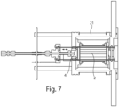
- Figure 7 shows a cut view of an example of the proposed plasma thruster in which the Faraday shield 21 is also indicated.
- the figure also indicates the movement possibility of the injector 4 by the double arrow in the figure.
- the plasma thruster is designed to resonate at a specific frequency, for example 40.68 MHz.
- the birdcage antenna 2 can be designed to resonate at this frequency by appropriate selection of the capacitors 12 in the end rings 11.
- the electronic components used in practice are not ideal and have always some deviations as well as the assembly and integration always have some tolerances, a fine adjustment of the resonance frequency is required. This is achieved by the movable injector 4 made of an electrically conductive material, in the present example brass.
- This injector can be moved along the thruster's axis of symmetry or cylindrical axis of the birdcage antenna as indicated in Fig. 7 .
- this injector 4 When this injector 4 is moved within/very close to the antenna region, the thruster's resonance frequency shifts upwards. The extent of movement defines the increment of frequency that can be finally controlled.
- a fine tuning of the resonance setting of the antenna with an interval range of 0.01 - 0.05 MHz is possible.
- the movement of the injector can be made manually or can also be achieved with an appropriate electric drive, in particular a stepper motor, to automatize the adjustment.
Landscapes
- Engineering & Computer Science (AREA)
- Chemical & Material Sciences (AREA)
- Combustion & Propulsion (AREA)
- Physics & Mathematics (AREA)
- Plasma & Fusion (AREA)
- Electromagnetism (AREA)
- General Engineering & Computer Science (AREA)
- Mechanical Engineering (AREA)
- Aviation & Aerospace Engineering (AREA)
- Remote Sensing (AREA)
- General Physics & Mathematics (AREA)
- Condensed Matter Physics & Semiconductors (AREA)
- Spectroscopy & Molecular Physics (AREA)
- Plasma Technology (AREA)
Abstract
Description
- The present invention relates to a plasma thruster, in particular for the propulsion of spacecrafts and/or satellites, comprising a cylindrical discharge channel and a RF antenna surrounding the discharge channel, said RF antenna when fed with RF power generating electromagnetic fields that ionize the propellant forming a plasma in the discharge channel that is then ejected through an outlet to generate thrust. The plasma thruster also comprises an injector for injecting the propellant into the discharge channel and a device for generating an axial static magnetic field in the discharge channel that has two main functions: one is to aid the formation of helicon waves within the plasma resulting in greater efficiency, and the second is, due to its divergence in the outlet region, to (partially) accelerate and eject a quasi-neutral plasma for thrust generation. Such a plasma thruster is also known as a helicon plasma thruster.
- In a helicon plasma thruster, the propellant that is injected into the cylindrical discharge channel is converted into a plasma by the electromagnetic waves of the radio frequency (RF) antenna. The axial magnetic field, which is typically generated by means of a solenoid or a system of permanent magnets, causes the generation of helicon waves in the plasma. These are circularly polarized and develop within the plasma that is formed inside the cylindrical discharge channel. The presence of helicon waves enables a more efficient power coupling than comparable inductive or capacitive plasma systems. By the combined effect of the electromagnetic field configuration produced by the RF antenna, and the static magnetic field, a quasi-neutral plasma is ejected at high velocity from the discharge channel to generate thrust. The quasi-neutrality of the plasma at the outlet removes the need of a neutralizer device that is commonly used for conventional electric thrusters, such as Hall-effect and gridded/RF ion thrusters. Such a plasma thruster can be used for propulsion of small spacecrafts and/or satellites, and can also be scaled for use on larger spacecrafts as well as on CubeSats. On the other hand, such a plasma thruster, may also be adapted as a plasma source for terrestrial applications.
- F. Romano et al., "RF Helicon-based Inductive Plasma Thruster (IPT) Design for an Atmosphere-Breathing Electric Propulsion System (ABEP)", Acta Astronautica, Vol. 176, 2020, pages 476 - 483, describes a helicon plasma thruster in which the RF antenna is a cylindrical birdcage antenna formed of a number of electrically conductive parallel legs connected to each other by a mechanical structure at the top and at the bottom of the legs, called end ring. The end rings comprise capacitors between adjacent legs in each gap to adjust the birdcage antenna resonance frequency to the one required by the application. The injector is made of an electrically conductive material and mounted movable along a symmetry axis of the plasma thruster allowing a fine tuning of the resonance frequency. The publication is silent about the technical realization of the birdcage antenna and only refers to a birdcage with eight legs in a high pass design. A critical issue of such an antenna is the connection of the legs with the end ring and capacitors which should be reliable and withstand the operational temperatures.
- It is thus an object of the present invention to provide an helicon-based plasma thruster which is particularly suitable for low power propulsion of smaller satellites or spacecrafts, providing a high efficiency by making use of a birdcage antenna, designed in such way to be easy to mount, reliable, and to withstand the operational temperatures.
- The object is achieved with the plasma thruster according to
claim 1. Advantageous embodiments are subject of the dependent claims or can be extracted from the subsequent portions of the description. - The proposed plasma thruster comprises a cylindrical discharge channel having an inlet for a propellant and an outlet, an injector for injecting the propellant through the inlet into the discharge channel, a RF antenna surrounding the discharge channel, said RF antenna when fed with RF power generating electromagnetic fields that ionize the propellant forming a plasma in the discharge channel that is then ejected through the outlet to generate thrust, and a device for generating an axial static magnetic field in the discharge channel, said magnetic field aiding the formation of helicon waves within the plasma as well as providing quasi-neutral plasma acceleration and ejection. In the proposed plasma thruster, the RF antenna is a cylindrical birdcage antenna formed of a number of electrically conductive parallel legs connected by two end rings on each side, wherein said end rings comprise one or several capacitors between adjacent legs in each case, said capacitors providing the electrical connection between the legs and defining the resonance frequency of the birdcage antenna. The injector is made of an electrically conductive material and mounted movable along the cylinder axis of the birdcage antenna for the fine tuning of the resonance frequency. The proposed plasma thruster is characterized in that the two end rings with the capacitors are soldered on two printed circuit boards (PCB) to which the legs are attached, said printed circuit boards having a through opening for the discharge channel.
- The proposed plasma thruster is operated at one of its resonant frequencies defined mainly by the antenna and the surrounding conductive surfaces. The antenna resonance frequency is, in particular, determined by the geometry of the legs and end rings and the number and capacitance of the implemented capacitors. To this end, the desired resonance frequency is set to the frequency output of the selected RF generator that provides power to the RF antenna, or vice versa if a variable frequency generator is used. The operation at one of the resonance frequencies minimizes losses (reflected power) and ohmic heating. Furthermore, as a birdcage antenna has multiple resonance frequencies
- (resonance modes), the operation at the specific m=1 resonance mode, produces a linearly polarized electromagnetic field within the cross section of the discharge channel that additionally provides a drift velocity for ions and electrons in the thrust direction. The additional axial magnetic field initiates helicon waves in the plasma with corresponding higher efficiency for plasma discharge as well as the effect of a magnetic nozzle which further accelerates the charged particles through the outlet. The thruster generates a quasi-neutral plasma jet that does not require an additional neutralizer, which is needed in alternative conventional Hall-effect and/or gridded/RF ion thrusters. The proposed birdcage antenna uses two printed circuit boards (PCB) onto which the capacitors are soldered, forming the end rings and to which the legs are attached. Those are easy to produce, and allow a reliable mounting which also ensures a resistance to heat of the corresponding electrical connections. The use of the PCBs allows a simple scalability for industrial fabrication of the thruster, i.e., an easy upscaling or downscaling. Furthermore, the use of PCBs on both ends of the birdcage antenna also allows to easy substitute the PCBs with PCBs having different capacitors for operation at different frequencies. Generally, the use of PCB facilitates manufacturing and integration in mass production.
- Preferably the legs comprise feet for fastening on both ends. Due to their geometry, these legs are preferably manufactured by a combination of a 3D-printing and a casting technology. Such a technology foresees the 3D printing of the desired geometry in plastic/wax. Such model is then surrounded with a fine plaster that then solidifies. The whole is heated and the plastic/wax melts/burns creating a mold. The fluid brass is injected and the solidifies, providing the desired part. This enables complex geometries like the formation of the legs with the desired curvature, with feet in one single piece which would be difficult to manufacture by conventional machining. The use of this combination of technologies also enables the possibility of rapid prototyping for the different antenna configurations and their verification which reduces development time and cost. The use of the 3D-printing technology with the casting method also prevents the degradation of electrical properties of the antenna resulting from the uncontrollable quality of standard 3D-printing methods, such as the internal porosity of the electrical conductor and the respective surface quality.
- In a preferred embodiment, the printed circuit boards are placed on isolating flanges to which the legs are fixed by means of screws and nuts (made of insulating material) via through holes in the feet, in the printed circuit boards and in the flanges. Preferably, the PCBs and the isolating flanges have the form of rings.
- In order to adapt or fine tune the resonance frequency of the birdcage antenna, the movable injector may comprise an electric drive, in particular a stepper motor or piezo drive, for movement of the injector along the cylinder axis of the birdcage antenna. This allows a remote controlled or automatic tuning of the resonance frequency. The proposed plasma thruster may very advantageously be used for propulsion of small spacecrafts and/or small satellites. Due to its relatively easy scalability, it can also be used on larger satellites. Nevertheless, also a use as plasma source for terrestrial applications is possible.
- The proposed plasma thruster is described in the following in detail by means of an exemplary embodiment and corresponding figures. The figures show:
- Fig. 1
- an example of a plasma thruster system in schematic representation;
- Fig. 2
- a schematic view of a birdcage antenna in high pass configuration as used in the present invention;
- Fig. 3
- a schematic view of the electromagnetic fields generated via the birdcage antenna and the externally applied axial static magnetic field;
- Fig. 4
- an example for the components and design of the birdcage antenna of the proposed plasma thruster;
- Fig. 5
- a photo of one of the printed circuit boards used for the birdcage antenna of
figure 4 in plan view; - Fig. 6
- a side view and a cross sectional view of one the legs of the birdcage antenna of
figure 4 ; and - Fig. 7
- a cross sectional view of an example of the proposed plasma thruster.
-
Figure 1 shows an example of a complete plasma thruster system using a plasma thruster according to the present invention. The plasma thruster consists of thecylindrical discharge channel 1 surrounded by thebirdcage antenna 2. Thebirdcage antenna 2 on the other hand is surrounded by a solenoid 3 (alternatively by an arrangement of permanent magnets) applying an axial static magnetic field along thedischarge channel 1. The propellant is injected into thedischarge channel 1 by aninjector 4. AnRF generator 5 combined with amatching network 6 provides the RF power to thebirdcage antenna 2. Thesolenoid 3 is supplied by aDC power supply 7. By applying the RF power to thebirdcage antenna 2 the propellant in thedischarge channel 1 is converted into aplasma 8 by the electromagnetic waves generated with thebirdcage antenna 2. The axial magnetic field provides the boundary condition for the generation of helicon waves in theplasma 8. The birdcage antenna-generated electromagnetic fields in conjunction with the applied static magnetic field provide the acceleration of thequasi-neutral plasma 8 which is ejected through the outlet of thedischarge channel 1 as aplasma jet 9 generating the corresponding thrust. -
Figure 2 shows a schematical representation of abirdcage antenna 2 in a high pass configuration used in the proposed plasma thruster. In this example thebirdcage antenna 2 consists of eightlegs 10 connected by two end rings 11 on each side. At eachend ring 11, between each twolegs 10,capacitors 12 are included in theend ring 11. Thesecapacitors 12 are used to provide the desired resonant frequency of thebirdcage antenna 2, which is related to the excitation frequency of the power unit (RF generator 5), for example a frequency of 40.68 MHz. In the present example, thebirdcage antenna 2 comprises eightlegs 10. The proposed plasma thruster may however also have abirdcage antenna 2 with a higher or lower number oflegs 10. - By operating at one of the resonant frequencies of the
birdcage antenna 2, the antenna is optimized, also from the point of view of minimizing the reflected power loss and ohmic losses. This means that an antenna impedance Zantenna = 50 + j0 Ω can be achieved. Other resonant modes have reactance of Xantenna = 0 Ω, but Rantenna can be different than 50 Ω. Standard RF generators, which have an output impedance of ZRF = 50 + j0 Ω can provide an electric power coupling of more than 99.99 %. At the desired resonance mode of the birdcage antenna, this also results in homogeneous and linearly polarized magnetic and electric fields (E1, B1) in the transverse cross section of the plasma cylinder (discharge channel 1). Such configurations provide drift velocity to both ions and electrons at the same time and in the thrust direction and, therefore, increases the thrust generated by the plasma thruster. Furthermore, the static magnetic field B0 provides a divergence at the outlet of thedischarge channel 1 and, thus, the effect of a magnetic nozzle, which further accelerates the quasi-neutral plasma and, thus, also increases the thrust. The corresponding electromagnetic fields (E1, B1) as well as the externally applied static magnetic field B0 are schematically indicated inFig. 3 . - A very important aspect of the present invention is the design of the
birdcage antenna 2.Figure 4 exemplary shows an explosion view of components for mounting thebirdcage antenna 2. Essential features of this antenna are the two printed circuit boards 14 (PCB), on which theantenna legs 10 are directly attached and to which thecapacitors 12 between the antenna legs are soldered. The end ring of thebirdcage antenna 2 is also formed on thecorresponding circuit boards 14. In the present example a very advantageous form of thelegs 10 withfeet 13 on each side is shown. In cross section perpendicular to the cylinder axis, thelegs 10 andfeet 13 have a cross sectional shape corresponding to the cross section of cylinder jacket sections of a hollow cylinder with the same cylinder axis. The legs are preferably formed by combining a 3D-printing and casting technology to produce the antenna legs out of copper. This system is particularly suitable for low power applications and thus for small satellites. - The 3D-printing and casting technology guarantees the conductivity of the copper and at the same time the desired shape of the legs (and feet). The printed
circuit boards 14 are connected to the antenna by means of PEEK screws andcorresponding nuts 17 as indicated inFig. 4 . These withstand high temperatures and at the same time insulate electrically. Thecapacitors 12 are soldered to the PCBs (as shown inFig. 5 ).RF ground 19 andRF input 18 are connected to theantenna legs 10. The grounding uses an electrically conductive screw to dissipate any reflected power. The RF input connector is directly soldered or clamped. Twoaluminum oxide flanges 15 are used to hold the structure together. These are electrically insulating and resistant to high temperatures. ThePTFE flange 16 attached at the top, has the task of holding the overall structure while providing electrical insulation. As can be seen fromFig. 4 , thelegs 10 are fixed via through holes in thefeet 13, thePCB board 14 and thealuminum oxide flanges 15 with the screws and nuts 17. -
Figure 5 shows a photo of one of thePCB boards 14 in plan view. In this plan view theend ring 11 of the birdcage antenna together with thecapacitors 12 can be recognized. The figure also shows the throughholes 20 for fixing thelegs 10. -
Figure 6 shows a side view and a top view on one of thelegs 10 with thefeet 13 on both ends together with exemplary dimensions in millimeters. The antenna itself is preferably isolated from the outside by a Faraday shield. This is made of a conductive material and - in the application on a satellite - is very advantageous as it isolates the satellite electronics from the electromagnetic fields of the plasma thruster. It also isolates the birdcage antenna from parasitic external electromagnetic fields. -
Figure 7 shows a cut view of an example of the proposed plasma thruster in which theFaraday shield 21 is also indicated. The figure also indicates the movement possibility of theinjector 4 by the double arrow in the figure. The plasma thruster is designed to resonate at a specific frequency, for example 40.68 MHz. Thebirdcage antenna 2 can be designed to resonate at this frequency by appropriate selection of thecapacitors 12 in the end rings 11. However, as the electronic components used in practice are not ideal and have always some deviations as well as the assembly and integration always have some tolerances, a fine adjustment of the resonance frequency is required. This is achieved by themovable injector 4 made of an electrically conductive material, in the present example brass. This injector can be moved along the thruster's axis of symmetry or cylindrical axis of the birdcage antenna as indicated inFig. 7 . When thisinjector 4 is moved within/very close to the antenna region, the thruster's resonance frequency shifts upwards. The extent of movement defines the increment of frequency that can be finally controlled. With such a movable injector, for example, a fine tuning of the resonance setting of the antenna with an interval range of 0.01 - 0.05 MHz is possible. The movement of the injector can be made manually or can also be achieved with an appropriate electric drive, in particular a stepper motor, to automatize the adjustment. -
- 1
- discharge channel
- 2
- birdcage antenna
- 3
- solenoid
- 4
- injector
- 5
- RF generator
- 6
- matching network
- 7
- DC power supply
- 8
- plasma
- 9
- plasma jet
- 10
- leg
- 11
- end ring
- 12
- capacitor
- 13
- foot
- 14
- PCB board
- 15
- Al2O3 flange
- 16
- PTFE flange
- 17
- PEEK screws and nuts
- 18
- RF input
- 19
- RF ground
- 20
- through hole
- 21
- Faraday shield
Claims (7)
- Plasma thruster, in particular for propulsion of spacecrafts and/or satellites, comprising:- a cylindrical discharge channel (1) having an inlet for a propellant and an outlet,- an injector (4) for injecting the propellant through the inlet into the discharge channel (1),- a RF antenna surrounding the discharge channel (1), said RF antenna when fed with RF power generating electromagnetic fields that ionize the propellant forming a plasma (8) in the discharge channel (1) that is then ejected through the outlet to generate thrust,- a device (3) for generating an axial static magnetic field in the discharge channel (1), said magnetic field providing boundary conditions for the formation of helicon waves within the plasma (8), as well as providing a magnetic nozzle effect at the outlet for quasi-neutral plasma acceleration,
wherein- the RF-antenna is a cylindrical birdcage antenna (2) formed of a number of electrically conductive parallel legs (10) connected by two end rings (11) on each side, said end rings (11) comprising one or several capacitors (12) between adjacent legs (10) in each case, said capacitors (12)
defining a resonance frequency of the birdcage antenna (2), and- the injector (4) is made of an electrically conductive material and mounted movable along a cylinder axis of the birdcage antenna (2) for fine tuning of the resonance frequency, characterized in thatthe two end rings (11) with the capacitors (12) are soldered on two printed circuit boards (14) to which the legs (10) are attached, said printed circuit boards (14) having a through opening for the discharge channel (1). - Plasma thruster according to claim 1, characterized in that
the legs (10) comprise feet (13) for fastening on both ends. - Plasma thruster according to claim 2, characterized in that
the legs (10) are formed by a combination of 3D-printing and casting technology. - Plasma thruster according to claim 2 or 3, characterized in that
the printed circuit boards (14) on which the capacitors (12) are soldered, are placed on isolating flanges (15) to which the legs (10) are fixed by means of screws and nuts (17) via through holes in the feet (13), in the printed circuit boards (14) and in the isolating flanges (15). - Plasma thruster according to claim 4, characterized in that
the printed circuit boards (14) and isolating flanges (15) have the form of rings. - Plasma thruster according to one or several of claims 1 to 5,
characterized in that
the injector (4) is provided with an electric drive, in particular a stepper motor or piezoelectric actuator, for movement of the injector (4) along the cylinder axis of the birdcage antenna (2). - Plasma thruster according to one or several of claims 1 to 6,
characterized in that
in cross-section perpendicular to the cylinder axis, the legs (10) and feet (13) have a cross-sectional shape corresponding to the cross-section of cylinder jacket sections of a hollow cylinder with the same cylinder axis.
Priority Applications (3)
| Application Number | Priority Date | Filing Date | Title |
|---|---|---|---|
| EP21213628.7A EP4194694B1 (en) | 2021-12-10 | 2021-12-10 | Plasma thruster with birdcage antenna |
| ES21213628T ES2987578T3 (en) | 2021-12-10 | 2021-12-10 | Plasma thruster with cage antenna |
| US18/077,291 US12140126B2 (en) | 2021-12-10 | 2022-12-08 | Plasma thruster with birdcage antenna |
Applications Claiming Priority (1)
| Application Number | Priority Date | Filing Date | Title |
|---|---|---|---|
| EP21213628.7A EP4194694B1 (en) | 2021-12-10 | 2021-12-10 | Plasma thruster with birdcage antenna |
Publications (3)
| Publication Number | Publication Date |
|---|---|
| EP4194694A1 true EP4194694A1 (en) | 2023-06-14 |
| EP4194694B1 EP4194694B1 (en) | 2024-05-08 |
| EP4194694C0 EP4194694C0 (en) | 2024-05-08 |
Family
ID=78829439
Family Applications (1)
| Application Number | Title | Priority Date | Filing Date |
|---|---|---|---|
| EP21213628.7A Active EP4194694B1 (en) | 2021-12-10 | 2021-12-10 | Plasma thruster with birdcage antenna |
Country Status (3)
| Country | Link |
|---|---|
| US (1) | US12140126B2 (en) |
| EP (1) | EP4194694B1 (en) |
| ES (1) | ES2987578T3 (en) |
Families Citing this family (1)
| Publication number | Priority date | Publication date | Assignee | Title |
|---|---|---|---|---|
| US12545439B2 (en) * | 2024-03-22 | 2026-02-10 | Eric Jason Crews | Tilt drive for electromagnetic force vectoring |
-
2021
- 2021-12-10 EP EP21213628.7A patent/EP4194694B1/en active Active
- 2021-12-10 ES ES21213628T patent/ES2987578T3/en active Active
-
2022
- 2022-12-08 US US18/077,291 patent/US12140126B2/en active Active
Non-Patent Citations (4)
| Title |
|---|
| F. ROMANO ET AL.: "RF Helicon-based Inductive Plasma Thruster (IPT) Design for an Atmosphere-Breathing Electric Propulsion System (ABEP", ACTA ASTRONAUTICA, vol. 176, 2020, pages 476 - 483, XP086325666, DOI: 10.1016/j.actaastro.2020.07.008 |
| LOPEZ RIOS NIBARDO ET AL: "Design and construction of an optimized transmit/receive hybrid birdcage resonator to improve full body images of medium-sized animals in 7T scanner", PLOS ONE, vol. 13, no. 2, 1 February 2018 (2018-02-01), pages e0192035, XP055916551, DOI: 10.1371/journal.pone.0192035 * |
| ROMANO F ET AL: "RF Helicon-based Inductive Plasma Thruster (IPT) Design for an Atmosphere-Breathing Electric Propulsion system (ABEP)", ACTA ASTRONAUTICA, PERGAMON PRESS, ELMSFORD, GB, vol. 176, 10 July 2020 (2020-07-10), pages 476 - 483, XP086325666, ISSN: 0094-5765, [retrieved on 20200710], DOI: 10.1016/J.ACTAASTRO.2020.07.008 * |
| ROMANO FRANCESCO ET AL: "Design, Set-Up, and First Ignition of the RF Helicon-based Plasma Thruster", SPACE PROPULSION 2020+1, 19 March 2021 (2021-03-19), pages 1 - 9, XP055916522, Retrieved from the Internet <URL:https://discoverer.space/wp-content/uploads/2021/07/247_ROMANO.pdf> [retrieved on 20220429] * |
Also Published As
| Publication number | Publication date |
|---|---|
| US12140126B2 (en) | 2024-11-12 |
| EP4194694B1 (en) | 2024-05-08 |
| US20230182929A1 (en) | 2023-06-15 |
| EP4194694C0 (en) | 2024-05-08 |
| ES2987578T3 (en) | 2024-11-15 |
Similar Documents
| Publication | Publication Date | Title |
|---|---|---|
| EP0434932B1 (en) | System for generating plasma | |
| US10269526B2 (en) | Hall current plasma source having a center-mounted cathode or a surface-mounted cathode | |
| RU2619389C2 (en) | Engine on the hall effect | |
| US12140126B2 (en) | Plasma thruster with birdcage antenna | |
| EP1627413B1 (en) | A high density plasma reactor | |
| KR20110094346A (en) | Plasma processing device and plasma generating device | |
| JP2015523688A (en) | Plasma source apparatus and method for generating a charged particle beam | |
| KR20210134602A (en) | plasma processing unit | |
| KR100466701B1 (en) | Compact helical resonator coil for ion implanter linear accelerator | |
| EP2123136A2 (en) | Improved plasma source | |
| US11346330B1 (en) | Additively manufactured components for electric propulsion thrusters | |
| EP2973639B1 (en) | Compact high-voltage plasma source for neutron generation | |
| US6936144B2 (en) | High frequency plasma source | |
| Liang et al. | Low-mass RF power inverter for cubesat applications using 3-D printed inductors | |
| Caldarelli | Radio-frequency plasma expansion in different magnetic nozzle configurations | |
| KR20140126351A (en) | Ribbon antenna for versatile operation and efficient rf power coupling | |
| Satoru Iizuka et al. | Electron cyclotron resonance devices with permanent magnets for production of large-diameter uniform plasmas | |
| JP3128139B2 (en) | Gas discharge device | |
| CN120188258A (en) | Parallel resonant antenna for radial plasma control | |
| CN115492736A (en) | Magnetic circuit-free microwave coaxial resonance ion thruster and thrust forming method | |
| Merino et al. | Plasma-RF Coupling in Electrodeless Plasma Thrusters for in-Space Propulsion | |
| US12489184B2 (en) | DC block and plasma generator using the same | |
| KR102961567B1 (en) | DC block and plasma generator using it | |
| Levush et al. | Cavity design for quasi-optical gyrotron and gyroklystron operation at harmonics of the cyclotron frequency | |
| Ferreira et al. | Hall Plasma Thruster Development for Nano and Micro-Satellites at PPL/UNB |
Legal Events
| Date | Code | Title | Description |
|---|---|---|---|
| PUAI | Public reference made under article 153(3) epc to a published international application that has entered the european phase |
Free format text: ORIGINAL CODE: 0009012 |
|
| STAA | Information on the status of an ep patent application or granted ep patent |
Free format text: STATUS: THE APPLICATION HAS BEEN PUBLISHED |
|
| AK | Designated contracting states |
Kind code of ref document: A1 Designated state(s): AL AT BE BG CH CY CZ DE DK EE ES FI FR GB GR HR HU IE IS IT LI LT LU LV MC MK MT NL NO PL PT RO RS SE SI SK SM TR |
|
| STAA | Information on the status of an ep patent application or granted ep patent |
Free format text: STATUS: REQUEST FOR EXAMINATION WAS MADE |
|
| 17P | Request for examination filed |
Effective date: 20230803 |
|
| RBV | Designated contracting states (corrected) |
Designated state(s): AL AT BE BG CH CY CZ DE DK EE ES FI FR GB GR HR HU IE IS IT LI LT LU LV MC MK MT NL NO PL PT RO RS SE SI SK SM TR |
|
| GRAP | Despatch of communication of intention to grant a patent |
Free format text: ORIGINAL CODE: EPIDOSNIGR1 |
|
| STAA | Information on the status of an ep patent application or granted ep patent |
Free format text: STATUS: GRANT OF PATENT IS INTENDED |
|
| RIC1 | Information provided on ipc code assigned before grant |
Ipc: F03H 1/00 20060101AFI20231121BHEP |
|
| INTG | Intention to grant announced |
Effective date: 20231207 |
|
| GRAS | Grant fee paid |
Free format text: ORIGINAL CODE: EPIDOSNIGR3 |
|
| GRAA | (expected) grant |
Free format text: ORIGINAL CODE: 0009210 |
|
| STAA | Information on the status of an ep patent application or granted ep patent |
Free format text: STATUS: THE PATENT HAS BEEN GRANTED |
|
| AK | Designated contracting states |
Kind code of ref document: B1 Designated state(s): AL AT BE BG CH CY CZ DE DK EE ES FI FR GB GR HR HU IE IS IT LI LT LU LV MC MK MT NL NO PL PT RO RS SE SI SK SM TR |
|
| REG | Reference to a national code |
Ref country code: GB Ref legal event code: FG4D |
|
| REG | Reference to a national code |
Ref country code: CH Ref legal event code: EP |
|
| REG | Reference to a national code |
Ref country code: DE Ref legal event code: R096 Ref document number: 602021013016 Country of ref document: DE |
|
| REG | Reference to a national code |
Ref country code: IE Ref legal event code: FG4D |
|
| U01 | Request for unitary effect filed |
Effective date: 20240516 |
|
| U07 | Unitary effect registered |
Designated state(s): AT BE BG DE DK EE FI FR IT LT LU LV MT NL PT SE SI Effective date: 20240528 |
|
| PG25 | Lapsed in a contracting state [announced via postgrant information from national office to epo] |
Ref country code: IS Free format text: LAPSE BECAUSE OF FAILURE TO SUBMIT A TRANSLATION OF THE DESCRIPTION OR TO PAY THE FEE WITHIN THE PRESCRIBED TIME-LIMIT Effective date: 20240908 |
|
| PG25 | Lapsed in a contracting state [announced via postgrant information from national office to epo] |
Ref country code: HR Free format text: LAPSE BECAUSE OF FAILURE TO SUBMIT A TRANSLATION OF THE DESCRIPTION OR TO PAY THE FEE WITHIN THE PRESCRIBED TIME-LIMIT Effective date: 20240508 |
|
| PG25 | Lapsed in a contracting state [announced via postgrant information from national office to epo] |
Ref country code: GR Free format text: LAPSE BECAUSE OF FAILURE TO SUBMIT A TRANSLATION OF THE DESCRIPTION OR TO PAY THE FEE WITHIN THE PRESCRIBED TIME-LIMIT Effective date: 20240809 |
|
| PG25 | Lapsed in a contracting state [announced via postgrant information from national office to epo] |
Ref country code: PL Free format text: LAPSE BECAUSE OF FAILURE TO SUBMIT A TRANSLATION OF THE DESCRIPTION OR TO PAY THE FEE WITHIN THE PRESCRIBED TIME-LIMIT Effective date: 20240508 |
|
| PG25 | Lapsed in a contracting state [announced via postgrant information from national office to epo] |
Ref country code: PL Free format text: LAPSE BECAUSE OF FAILURE TO SUBMIT A TRANSLATION OF THE DESCRIPTION OR TO PAY THE FEE WITHIN THE PRESCRIBED TIME-LIMIT Effective date: 20240508 Ref country code: NO Free format text: LAPSE BECAUSE OF FAILURE TO SUBMIT A TRANSLATION OF THE DESCRIPTION OR TO PAY THE FEE WITHIN THE PRESCRIBED TIME-LIMIT Effective date: 20240808 Ref country code: IS Free format text: LAPSE BECAUSE OF FAILURE TO SUBMIT A TRANSLATION OF THE DESCRIPTION OR TO PAY THE FEE WITHIN THE PRESCRIBED TIME-LIMIT Effective date: 20240908 Ref country code: HR Free format text: LAPSE BECAUSE OF FAILURE TO SUBMIT A TRANSLATION OF THE DESCRIPTION OR TO PAY THE FEE WITHIN THE PRESCRIBED TIME-LIMIT Effective date: 20240508 Ref country code: GR Free format text: LAPSE BECAUSE OF FAILURE TO SUBMIT A TRANSLATION OF THE DESCRIPTION OR TO PAY THE FEE WITHIN THE PRESCRIBED TIME-LIMIT Effective date: 20240809 Ref country code: RS Free format text: LAPSE BECAUSE OF FAILURE TO SUBMIT A TRANSLATION OF THE DESCRIPTION OR TO PAY THE FEE WITHIN THE PRESCRIBED TIME-LIMIT Effective date: 20240808 |
|
| REG | Reference to a national code |
Ref country code: ES Ref legal event code: FG2A Ref document number: 2987578 Country of ref document: ES Kind code of ref document: T3 Effective date: 20241115 |
|
| U20 | Renewal fee for the european patent with unitary effect paid |
Year of fee payment: 4 Effective date: 20241211 |
|
| PG25 | Lapsed in a contracting state [announced via postgrant information from national office to epo] |
Ref country code: CZ Free format text: LAPSE BECAUSE OF FAILURE TO SUBMIT A TRANSLATION OF THE DESCRIPTION OR TO PAY THE FEE WITHIN THE PRESCRIBED TIME-LIMIT Effective date: 20240508 |
|
| PG25 | Lapsed in a contracting state [announced via postgrant information from national office to epo] |
Ref country code: SK Free format text: LAPSE BECAUSE OF FAILURE TO SUBMIT A TRANSLATION OF THE DESCRIPTION OR TO PAY THE FEE WITHIN THE PRESCRIBED TIME-LIMIT Effective date: 20240508 Ref country code: RO Free format text: LAPSE BECAUSE OF FAILURE TO SUBMIT A TRANSLATION OF THE DESCRIPTION OR TO PAY THE FEE WITHIN THE PRESCRIBED TIME-LIMIT Effective date: 20240508 |
|
| PG25 | Lapsed in a contracting state [announced via postgrant information from national office to epo] |
Ref country code: SM Free format text: LAPSE BECAUSE OF FAILURE TO SUBMIT A TRANSLATION OF THE DESCRIPTION OR TO PAY THE FEE WITHIN THE PRESCRIBED TIME-LIMIT Effective date: 20240508 |
|
| PG25 | Lapsed in a contracting state [announced via postgrant information from national office to epo] |
Ref country code: SM Free format text: LAPSE BECAUSE OF FAILURE TO SUBMIT A TRANSLATION OF THE DESCRIPTION OR TO PAY THE FEE WITHIN THE PRESCRIBED TIME-LIMIT Effective date: 20240508 Ref country code: SK Free format text: LAPSE BECAUSE OF FAILURE TO SUBMIT A TRANSLATION OF THE DESCRIPTION OR TO PAY THE FEE WITHIN THE PRESCRIBED TIME-LIMIT Effective date: 20240508 Ref country code: RO Free format text: LAPSE BECAUSE OF FAILURE TO SUBMIT A TRANSLATION OF THE DESCRIPTION OR TO PAY THE FEE WITHIN THE PRESCRIBED TIME-LIMIT Effective date: 20240508 Ref country code: CZ Free format text: LAPSE BECAUSE OF FAILURE TO SUBMIT A TRANSLATION OF THE DESCRIPTION OR TO PAY THE FEE WITHIN THE PRESCRIBED TIME-LIMIT Effective date: 20240508 |
|
| REG | Reference to a national code |
Ref country code: DE Ref legal event code: R097 Ref document number: 602021013016 Country of ref document: DE |
|
| PLBE | No opposition filed within time limit |
Free format text: ORIGINAL CODE: 0009261 |
|
| STAA | Information on the status of an ep patent application or granted ep patent |
Free format text: STATUS: NO OPPOSITION FILED WITHIN TIME LIMIT |
|
| 26N | No opposition filed |
Effective date: 20250211 |
|
| PG25 | Lapsed in a contracting state [announced via postgrant information from national office to epo] |
Ref country code: MC Free format text: LAPSE BECAUSE OF FAILURE TO SUBMIT A TRANSLATION OF THE DESCRIPTION OR TO PAY THE FEE WITHIN THE PRESCRIBED TIME-LIMIT Effective date: 20240508 |
|
| PG25 | Lapsed in a contracting state [announced via postgrant information from national office to epo] |
Ref country code: IE Free format text: LAPSE BECAUSE OF NON-PAYMENT OF DUE FEES Effective date: 20241210 |
|
| REG | Reference to a national code |
Ref country code: CH Ref legal event code: U11 Free format text: ST27 STATUS EVENT CODE: U-0-0-U10-U11 (AS PROVIDED BY THE NATIONAL OFFICE) Effective date: 20260101 |
|
| PGFP | Annual fee paid to national office [announced via postgrant information from national office to epo] |
Ref country code: GB Payment date: 20251204 Year of fee payment: 5 |
|
| U20 | Renewal fee for the european patent with unitary effect paid |
Year of fee payment: 5 Effective date: 20251217 |
|
| PGFP | Annual fee paid to national office [announced via postgrant information from national office to epo] |
Ref country code: ES Payment date: 20260102 Year of fee payment: 5 |
|
| PGFP | Annual fee paid to national office [announced via postgrant information from national office to epo] |
Ref country code: CH Payment date: 20260101 Year of fee payment: 5 |