EP4194691A1 - Improvements relating to stray current detection in wind turbine generators - Google Patents
Improvements relating to stray current detection in wind turbine generators Download PDFInfo
- Publication number
- EP4194691A1 EP4194691A1 EP23153682.2A EP23153682A EP4194691A1 EP 4194691 A1 EP4194691 A1 EP 4194691A1 EP 23153682 A EP23153682 A EP 23153682A EP 4194691 A1 EP4194691 A1 EP 4194691A1
- Authority
- EP
- European Patent Office
- Prior art keywords
- electrical
- power generating
- generator
- generating assembly
- current measuring
- Prior art date
- Legal status (The legal status is an assumption and is not a legal conclusion. Google has not performed a legal analysis and makes no representation as to the accuracy of the status listed.)
- Granted
Links
Images



Classifications
-
- F—MECHANICAL ENGINEERING; LIGHTING; HEATING; WEAPONS; BLASTING
- F03—MACHINES OR ENGINES FOR LIQUIDS; WIND, SPRING, OR WEIGHT MOTORS; PRODUCING MECHANICAL POWER OR A REACTIVE PROPULSIVE THRUST, NOT OTHERWISE PROVIDED FOR
- F03D—WIND MOTORS
- F03D17/00—Monitoring or testing of wind motors, e.g. diagnostics
- F03D17/009—Monitoring or testing of wind motors, e.g. diagnostics characterised by the purpose
- F03D17/021—Monitoring or testing of wind motors, e.g. diagnostics characterised by the purpose for monitoring power or current
-
- F—MECHANICAL ENGINEERING; LIGHTING; HEATING; WEAPONS; BLASTING
- F03—MACHINES OR ENGINES FOR LIQUIDS; WIND, SPRING, OR WEIGHT MOTORS; PRODUCING MECHANICAL POWER OR A REACTIVE PROPULSIVE THRUST, NOT OTHERWISE PROVIDED FOR
- F03D—WIND MOTORS
- F03D17/00—Monitoring or testing of wind motors, e.g. diagnostics
-
- F—MECHANICAL ENGINEERING; LIGHTING; HEATING; WEAPONS; BLASTING
- F03—MACHINES OR ENGINES FOR LIQUIDS; WIND, SPRING, OR WEIGHT MOTORS; PRODUCING MECHANICAL POWER OR A REACTIVE PROPULSIVE THRUST, NOT OTHERWISE PROVIDED FOR
- F03D—WIND MOTORS
- F03D9/00—Adaptations of wind motors for special use; Combinations of wind motors with apparatus driven thereby; Wind motors specially adapted for installation in particular locations
- F03D9/20—Wind motors characterised by the driven apparatus
- F03D9/25—Wind motors characterised by the driven apparatus the apparatus being an electrical generator
-
- G—PHYSICS
- G01—MEASURING; TESTING
- G01R—MEASURING ELECTRIC VARIABLES; MEASURING MAGNETIC VARIABLES
- G01R15/00—Details of measuring arrangements of the types provided for in groups G01R17/00 - G01R29/00, G01R33/00 - G01R33/26 or G01R35/00
- G01R15/14—Adaptations providing voltage or current isolation, e.g. for high-voltage or high-current networks
- G01R15/18—Adaptations providing voltage or current isolation, e.g. for high-voltage or high-current networks using inductive devices, e.g. transformers
- G01R15/181—Adaptations providing voltage or current isolation, e.g. for high-voltage or high-current networks using inductive devices, e.g. transformers using coils without a magnetic core, e.g. Rogowski coils
-
- F—MECHANICAL ENGINEERING; LIGHTING; HEATING; WEAPONS; BLASTING
- F03—MACHINES OR ENGINES FOR LIQUIDS; WIND, SPRING, OR WEIGHT MOTORS; PRODUCING MECHANICAL POWER OR A REACTIVE PROPULSIVE THRUST, NOT OTHERWISE PROVIDED FOR
- F03D—WIND MOTORS
- F03D7/00—Controlling wind motors
- F03D7/02—Controlling wind motors the wind motors having rotation axis substantially parallel to the air flow entering the rotor
- F03D7/0272—Controlling wind motors the wind motors having rotation axis substantially parallel to the air flow entering the rotor by measures acting on the electrical generator
-
- G—PHYSICS
- G01—MEASURING; TESTING
- G01R—MEASURING ELECTRIC VARIABLES; MEASURING MAGNETIC VARIABLES
- G01R31/00—Arrangements for testing electric properties; Arrangements for locating electric faults; Arrangements for electrical testing characterised by what is being tested not provided for elsewhere
- G01R31/34—Testing dynamo-electric machines
- G01R31/343—Testing dynamo-electric machines in operation
-
- Y—GENERAL TAGGING OF NEW TECHNOLOGICAL DEVELOPMENTS; GENERAL TAGGING OF CROSS-SECTIONAL TECHNOLOGIES SPANNING OVER SEVERAL SECTIONS OF THE IPC; TECHNICAL SUBJECTS COVERED BY FORMER USPC CROSS-REFERENCE ART COLLECTIONS [XRACs] AND DIGESTS
- Y02—TECHNOLOGIES OR APPLICATIONS FOR MITIGATION OR ADAPTATION AGAINST CLIMATE CHANGE
- Y02E—REDUCTION OF GREENHOUSE GAS [GHG] EMISSIONS, RELATED TO ENERGY GENERATION, TRANSMISSION OR DISTRIBUTION
- Y02E10/00—Energy generation through renewable energy sources
- Y02E10/70—Wind energy
- Y02E10/72—Wind turbines with rotation axis in wind direction
Definitions
- the invention relates to a wind turbine generator equipped with an arrangement for monitoring stray currents through various components of that generator in order to provide diagnostics and protection.
- a typical Horizontal Axis Wind Turbine comprises a tower, a nacelle on top of the tower, a rotating hub or 'rotor' mounted to the nacelle and a plurality of wind turbine rotor blades coupled to the hub.
- the nacelle houses many functional components of the wind turbine, including for example a generator, gearbox, drive train and rotor brake assembly, as well as convertor equipment for converting the mechanical energy at the rotor into electrical energy for provision to the grid.
- the gearbox steps up the rotational speed of the low speed main shaft and drives a gearbox output shaft.
- the gearbox output shaft in turn drives the generator, which converts the rotation of the gearbox output shaft into electricity.
- the electricity generated by the generator may then be converted as required before being supplied to an appropriate consumer, for example an electrical grid distribution system.
- the generator In a wind turbine system, the generator necessarily generates high voltages, and this is particularly true for modern-day wind turbines which pursue high voltage generation for electrical efficiency.
- a challenge to the design of such generator assemblies is that the generated high voltages can also induce unintentional currents in other components of the generator and associated components. These so-called 'stray currents' can result in electrical arcing between adjacent components, and this can, in turn, cause damage such as pitting and welding. Bearings are particularly susceptible to this kind of damage and so it is desirable to detect that such 'stray currents' are within acceptable levels. It is also desirable to channel such currents along grounding routes that will not cause problems.
- an electrical power generating assembly for a wind turbine.
- the electrical power generating assembly comprises a gearbox comprising a gearbox output shaft, a generator comprising a rotor that is coupled to the gearbox output shaft; and a current measuring module located between the gearbox and the generator.
- the current measuring module comprises: an electrical pickup mounted to the electrical power generating assembly wherein the electrical pickup includes an electrical contact that engages with a slip ring associated with the rotor.
- the current measuring module further comprises: a first current measuring device mounted with respect to the electrical pickup to detect current flowing therethrough; and a second current measuring device mounted with respect to the electrical pickup to detect current flowing through a component associated with the gearbox output shaft.
- the above-described assembly is advantageous as it enables diagnostics of stray current levels in various components of the electrical power generating assembly (and particularly in the generator components such as the rotor) to be easily carried out. Furthermore, the above-described assembly may be configurable to prevent excess build-up of stray currents by, for example, taking protective measures if the detected stray current in certain components exceeds a predetermined threshold. This advantageously helps to prevent damage to key turbine components that may result from electrical arcing caused by the stray currents.
- the electrical pickup is stationary with respect to the rotor, in use, in the sense that the electrical pickup does not rotate with the rotor.
- the current measuring module is provided as an integrated unit. Providing the current measuring module as an integrated unit, with all of the components being mounted together somehow to one unit prior to installation increases the ease of installation of the module in its desired location between the generator and gearbox.
- each of the first and second current measuring devices comprises an elongate sensing element arranged to substantially encircle the generator rotor. As the current measuring devices encircle the generator rotor, they are able to easily detect stray current that builds up at least within the rotor, but also anything electrically connected to it either capacitively or galvanically. Each of the first and second current measuring devices may comprise a Rogowski coil. Thus, the current measuring devices are configured to detect current in any component located radially inward of the aperture defined by the loop of the measuring device.
- the first current measuring device is mounted radially-outboard of the electrical pickup, and the second current measuring device is mounted radially-inboard of the electrical pickup.
- the above-described arrangement of current measuring devices provides a useful mechanism for differentiating between stray current detected at the two radial locations.
- this arrangement enables a determination of the stray current produced by the generator rotor (and scavenged by the electrical pickup) to be carried out - this stray current will correspond to the difference between the current detected by the two devices. This thereby enables stray current diagnostic and protection measures to be implemented specifically in respect of the generator.
- the current measuring module further comprises a mounting disk.
- the electrical contact, and the first and second current measuring devices are configured to be mounted to the mounting disk.
- the mounting disk is configured to be mounted to a housing of the gearbox.
- the electrical power generating assembly further comprises a control system in operative communication with the current measuring module, the control system configured to identify, based on the current detected by the first and/or second current measuring device, anomalies in the detected current.
- the current measuring module thereby facilitates the implementation of stray current diagnostic and protection measures in respect of various components of the electrical power generating assembly, particularly the generator.
- the electrical pickup comprises a brush module.
- the brush module may comprise one or more linear brushes.
- the term 'linear' is used to indicate that individual elements forming the brush array (e.g. filaments or fibres) are arranged in a generally planar manner with respect to one another.
- the individual filament/fibre elements forming the brush array may be arranged generally parallel to one another, for example in a line along a channel provided in the brush component.
- the one or more linear brushes may extend along an axis that is generally aligned with a rotational axis of the rotor.
- the dual current sensors may be combined with an electrical pickup that has brushes arranged in a radial direction relative to the rotor.
- the one or more linear brushes are carbon fibre brushes.
- other electrically conductive materials could also be used to form the individual brush elements, such as copper or brass wires or braids.
- a wind turbine comprising the electrical power generating assembly substantially as described hereinabove.
- the wind turbine comprises a wind turbine tower, a nacelle rotatably coupled to the tower, a rotating hub mounted to the nacelle, and a plurality of wind turbine blades coupled to the hub.
- the nacelle comprises the electrical power generating assembly.
- an electrical power generating assembly for a wind turbine.
- the electrical power generating assembly comprises a gearbox comprising a gearbox output shaft, a generator comprising a rotor that is coupled to the gearbox output shaft; and an electrical pickup mounted to the electrical power generating assembly.
- the electrical pickup comprises: a contact disk associated with and extending radially away from the generator rotor; and at least one electrical contact aligned with an axis of the generator rotor, and configured to be in electrical contact with an electrical contact surface of the contact disk so as to pick up current from components of the electrical power generating assembly.
- the axial orientation of the electrical contacts also increases the flexibility of the electrical pickup assembly for use with multiple different generators, each having a different rotor diameter. It will be appreciated that the above description of 'alignment' with the generator rotor axis should not be limited strictly to 'parallel alignment'.
- the electrical contacts may in fact be angled slightly with respect to the generator rotor axis, provided the required electrical contact with the contact disk is attained (i.e. provided the electrical contacts do not extend perpendicular to the generator rotor axis).
- the at least one electrical contact comprises a linear electrical brush array.
- the electrical brush array comprises a plurality of brush fibres, extending in a direction aligned with (and preferably substantially parallel) to a rotational axis of the generator rotor, so as to interface with the electrical contact surface of the contact disk.
- the axially-oriented arrangement of the electrical contact brush array (in combination with the radially-extending contact disk) ensures good electrical connection between the electrical pickup and the rotor without requiring precise detailed alignment of the electrical contacts with the rotor (as might be required for axially-oriented contacts).
- the electrical contact is affixed to a mount associated with a housing of the gearbox.
- the electrical contact pickup may comprise a first current measuring device mounted with respect to the electrical pickup to detect current flowing therethrough and/or a second current measuring device mounted with respect to the electrical pickup to detect current flowing through a component associated with the gearbox output shaft.
- each of the first and second current measuring devices may comprise an elongate sensing element arranged to substantially encircle the generator rotor.
- the first current measuring device is mounted radially-outboard of the electrical pickup
- the second current measuring device is mounted radially-inboard of the electrical pickup.
- a wind turbine comprising the electrical power generating assembly substantially as described hereinabove.
- the wind turbine comprises a wind turbine tower, a nacelle rotatably coupled to the tower, a rotating hub mounted to the nacelle, and a plurality of wind turbine blades coupled to the hub.
- the nacelle comprises the electrical power generating assembly.
- FIG. 1 illustrates a typical Horizontal Axis Wind Turbine (HAWT) in which an electrical power generating assembly according to an embodiment of the invention may be implemented.
- HAWT Horizontal Axis Wind Turbine
- this particular image depicts an on-shore wind turbine, it will be understood that equivalent features will also be found on off-shore wind turbines.
- the wind turbines are referred to as 'horizontal axis', it will be appreciated by the skilled person that for practical purposes, the axis is usually slightly inclined to prevent contact between the rotor blades and the wind turbine tower in the event of strong winds.
- the wind turbine 1 comprises a tower 2, a nacelle 4 rotatably coupled to the top of the tower 2 by a yaw system (not shown), a rotating hub or 'rotor' 8 mounted to the nacelle 4 and a plurality of wind turbine rotor blades 10 coupled to the hub 8.
- the nacelle 4 and rotor blades 10 are turned and directed into the wind direction by the yaw system.
- the nacelle 4 may include an electrical power generating assembly 20, which includes a gearbox 22 and a generator 24.
- a main shaft 26, is supported by a main bearing housing 25 and is connected to, and driven by, the rotor 8 and provides input drive to the gearbox 22.
- the gearbox 22 steps up the rotational speed of the low speed main shaft 26 via internal gears (not shown) and drives a gearbox output shaft (not shown).
- the gearbox output shaft in turn drives the generator 24, which converts the rotation of the gearbox output shaft into electricity.
- the electricity generated by the generator 24 may then be converted by other components (not shown) as required before being supplied to an appropriate consumer, for example an electrical grid distribution system.
- So-called "direct drive" wind turbines that do not use gearboxes are also known. In a direct drive wind turbine, the generator is directly driven by a shaft connected to the rotor.
- a so called 'pitch tube' 27 may be arranged to pass along the centre of the generator 24 and the gearbox 22 to provide hydraulic services to the
- the gearbox 22 and generator 24 may be coupled together in an integrated unit to form the electrical power generating assembly 20.
- Such an integrated unit is shown in Figure 2 , whereas Figure 3 shows a longitudinal section through the generator by way of a specific example, and as a separate sub assembly to the generator
- a gearbox housing 30 is generally cylindrical in form and is oriented such that its major rotational axis (indicated by the line 'Y' in Figure 3 ) is horizontal, in the orientation of the drawings.
- the cylindrical configuration of the gearbox housing 30 is due to the specific type of gearbox that is used in the illustrated embodiment, which is an epicyclic gearbox.
- an epicyclic gearbox comprises a series of planet gears that are arranged about a central sun gear, and which collectively are arranged within an encircling ring gear. The ratio of the number of teeth between the ring gear, the planet gear and the sun gears determines the gear ratio of the gearbox.
- gearbox is not the principal subject of the invention. Suffice to say that other gearbox configurations could also be used, although it is currently envisaged that an epicyclic gearbox provides an elegant solution fit for the confines of a wind turbine nacelle.
- the generator 24 in the illustrated embodiment is an IPM (interior permanent magnet) electric machine having an external stator 36 which surrounds the rotor 32.
- the rotor 32 includes a rotor shaft 32a which couples to a gearbox output shaft (not shown), and a radially out rotor core 32b which carries, support or other houses the permanent magnet elements of the rotor 32.
- the stator 36 includes a stator core 38 which surrounds the rotor core 32b.
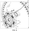
- a current measuring module 40 may be incorporated into the generator-gearbox integrated assembly, and is located between the gearbox and the generator. Specifically, the current measuring module 40 in the illustrated embodiment is associated with and interfaces with the generator rotor 32 It will be noted at this point that the current measuring module 40 is also shown in Figure 3 , and is highlighted by the circles labelled 'A'. However, Figure 4 shows the current measuring module 40 in more detail for ease of understanding. The location and configuration of the current measuring module 40 are shown in greater detail in the close-up illustration of Figure 5 .
- the illustrated current measuring module 40 comprises an electrical pickup 42 which is arranged to scavenge 'stray current' induced in components of the generator 24.
- the electrical pickup 42 is mounted so as to be stationary with respect to the generator rotor 32 in use.
- the electrical pickup 42 comprises a plurality of electrical contacts 44 that are mounted to a mounting disk or bracket 46 and arranged to encircle the gearbox output shaft and the generator rotor 32.
- Each of the electrical contacts 44 engages and interfaces with a flange or slip ring 48 that is associated with and extends radially away from the rotor 32.
- the electrical contacts are made of electrically conductive material (for example, carbon fibre or copper) and may take the form of electrical brush arrays. These are described in greater detail below.
- the current measuring module 40 further comprises first and second current measuring devices 50, 52 which are configured to measure current flowing through components of the generator-gearbox integrated assembly.
- the first and second current measuring devices 50, 52 each correspond to an elongate current-measuring element that substantially encircles the rotational axis of the generator 24.
- each device 50, 52 is a Rogowski coil which, as the skilled person would be aware, is effectively a flexible current transformer that is arranged to enable monitoring and measurement of alternating current.
- the pair of current measuring Rogowski coils 50, 52 are mounted concentrically to the mounting disk 46, such that each coil 50, 52 extends in a loop between the electrical contacts 44 and substantially encircles the gearbox output shaft, and the radially inwards parts of the generator rotor 32.
- the Rogowski coils 50, 52 are mounted to the mounting disk 46 using fastening means 53 (such as clamps), and are positioned on radially opposing sides of the electrical contacts 44; in other words, the electrical contacts 44 are located in between the two coils 50, 52.
- fastening means 53 such as clamps
- each of the Rogowski coils 50, 52 is configured to monitor and measure the current induced in the component (or components) located radially-inboard of the Rogowski coil in question, that is to say the components that are encircled by the coils.
- the first current measuring Rogowski coil 50 is mounted at a radially-outboard location on the mounting disk 46, relative to the electrical contacts 44, and is configured to measure the current induced in and flowing through the electrical contacts 44, and hence in electrical pickup 42 as a whole, in addition to the other components that are radially inwards of the coil 50.
- the second current measuring Rogowski coil 52 is mounted at a radially-inboard location on the mounting disk 46, relative to the electrical contacts 44, and is configured to measure the current induced in and flowing through components located radially-inboard of the electrical pickup 42, for example the gearbox output shaft and pitch tube 27 (not shown in Figs. 4-6 , but shown in Fig. 2 ), as well as the generator rotor 32.
- Loose ends of the pair of Rogowski coils 50, 52 extend radially outwards away from the electrical pickup 42 to a connection or interface (indicated in Figure 5 using arrows) with electronic conversion and control circuitry 54.
- This circuitry is configured to monitor and analyse the output signal from the Rogowski coils 50, 52 and may also comprise or be in operative communication with, for example, a generator control unit or system data bus that is configured to take action based on the measured 'stray current' values.
- the difference in the currents measured by the pair of Rogowski coils 50, 52 will correspond to the 'stray current' accumulated in the electrical contacts 44 (e.g. from the generator rotor 32 and the pitch tube 28).
- the illustrated embodiment therefore enables diagnostics of the stray current levels in, for example, the generator 24, to be carried out. Furthermore, protective action may also be taken if the stray current value measured by one or both of the Rogowski coils 50, 52 exceeds a predetermined threshold. As a result, build-up of stray current in the generator 24 may be easily detected and protective measures implemented, thereby avoiding or mitigating any electrical arcing and associated damage that could result.
- FIG. 6 A close-up side perspective view highlighting additional details of the current measuring module 40 configuration is shown in Figure 6 ; this view is taken vertically along a section of Figure 5 , perpendicularly through the axis of the mounting disk 46, but also shows further components to the left hand side of the current measuring module 40 that are not in Figure 5 .
- FIG 6 shows that the mounting disk 46 comprises a plurality of supports 55 in the form of shelves or ledges, each of which extends perpendicular to the annular main face of the mounting disk 46, and substantially parallel to the rotational axis of the generator 24.
- Each shelf 54 supports a corresponding one of the electrical contacts 44, the electrical contacts 44 being mounted to their respective support 55 by fastening means (not shown) such as bolts.
- each electrical contact 44 takes the form of a generally linear electrical brush array comprising a plurality of brush filaments or fibres 56 which extend outwards, being aligned with and preferably substantially parallel to the rotational axis of the generator 24 (and also to the corresponding support 55), to interface with the slip ring 48 that is associated with the rotor 32.
- the term 'linear' is used here to indicate that the brush fibres 56 are arranged in a generally planar manner - for example, located parallel to one another along and within a linear channel provided in the electrical contact.
- the brush fibres 56 may be made of carbon fibre, or any suitable electrically conductive material such as copper or graphite.
- the axially-extending alignment of the brush fibres 56 in combination with the provision of the radially-extending slip ring 48 associated with the rotor 32, is particularly advantageous. This is because it increases the flexibility of the illustrated electrical pickup 42 for use with a variety of generators having different rotor shaft diameters.
- the current measuring module 40 effectively needs to be incorporated into its desired location (between the gearbox 22 and the generator 24) via a 'blind assembly' process.
- the configuration of the electrical pickup utilised in embodiments of the invention increases the ease with which blind assembly may take place, whilst simultaneously ensuring that the brush fibres 56 (when installed in situ) will still have a good electrical connectivity with the generator rotor 32 via the slip ring 48; however the requirement to have a precise alignment of the brush fibres 56 with components such as the generator rotor 32 and/or main shaft 26 is obviated.
- the advantages of the illustrated configuration are particularly evident when considered in comparison with electrical pickups comprising a brush array in which the brush fibres extend radially inwards (e.g. as a ring around the rotational axis of the generator).
Landscapes
- Engineering & Computer Science (AREA)
- Mechanical Engineering (AREA)
- Sustainable Development (AREA)
- Sustainable Energy (AREA)
- Chemical & Material Sciences (AREA)
- Combustion & Propulsion (AREA)
- Life Sciences & Earth Sciences (AREA)
- General Engineering & Computer Science (AREA)
- Power Engineering (AREA)
- Physics & Mathematics (AREA)
- General Physics & Mathematics (AREA)
- Wind Motors (AREA)
- Investigating Or Analyzing Materials By The Use Of Magnetic Means (AREA)
Abstract
Description
- The invention relates to a wind turbine generator equipped with an arrangement for monitoring stray currents through various components of that generator in order to provide diagnostics and protection.
- Wind turbines convert kinetic energy from the wind into electrical energy, using a large rotor with a number of rotor blades. A typical Horizontal Axis Wind Turbine (HAWT) comprises a tower, a nacelle on top of the tower, a rotating hub or 'rotor' mounted to the nacelle and a plurality of wind turbine rotor blades coupled to the hub. The nacelle houses many functional components of the wind turbine, including for example a generator, gearbox, drive train and rotor brake assembly, as well as convertor equipment for converting the mechanical energy at the rotor into electrical energy for provision to the grid. The gearbox steps up the rotational speed of the low speed main shaft and drives a gearbox output shaft. The gearbox output shaft in turn drives the generator, which converts the rotation of the gearbox output shaft into electricity. The electricity generated by the generator may then be converted as required before being supplied to an appropriate consumer, for example an electrical grid distribution system.
- In a wind turbine system, the generator necessarily generates high voltages, and this is particularly true for modern-day wind turbines which pursue high voltage generation for electrical efficiency. However, a challenge to the design of such generator assemblies is that the generated high voltages can also induce unintentional currents in other components of the generator and associated components. These so-called 'stray currents' can result in electrical arcing between adjacent components, and this can, in turn, cause damage such as pitting and welding. Bearings are particularly susceptible to this kind of damage and so it is desirable to detect that such 'stray currents' are within acceptable levels. It is also desirable to channel such currents along grounding routes that will not cause problems.
- It is against this background that the invention has been devised.
- According to a first aspect of the invention, there is provided an electrical power generating assembly for a wind turbine. The electrical power generating assembly comprises a gearbox comprising a gearbox output shaft, a generator comprising a rotor that is coupled to the gearbox output shaft; and a current measuring module located between the gearbox and the generator. The current measuring module comprises: an electrical pickup mounted to the electrical power generating assembly wherein the electrical pickup includes an electrical contact that engages with a slip ring associated with the rotor. The current measuring module further comprises: a first current measuring device mounted with respect to the electrical pickup to detect current flowing therethrough; and a second current measuring device mounted with respect to the electrical pickup to detect current flowing through a component associated with the gearbox output shaft.
- The above-described assembly is advantageous as it enables diagnostics of stray current levels in various components of the electrical power generating assembly (and particularly in the generator components such as the rotor) to be easily carried out. Furthermore, the above-described assembly may be configurable to prevent excess build-up of stray currents by, for example, taking protective measures if the detected stray current in certain components exceeds a predetermined threshold. This advantageously helps to prevent damage to key turbine components that may result from electrical arcing caused by the stray currents.
- Note that, preferably, the electrical pickup is stationary with respect to the rotor, in use, in the sense that the electrical pickup does not rotate with the rotor.
- In a preferred embodiment of the invention, the current measuring module is provided as an integrated unit. Providing the current measuring module as an integrated unit, with all of the components being mounted together somehow to one unit prior to installation increases the ease of installation of the module in its desired location between the generator and gearbox.
- In some embodiments, each of the first and second current measuring devices comprises an elongate sensing element arranged to substantially encircle the generator rotor. As the current measuring devices encircle the generator rotor, they are able to easily detect stray current that builds up at least within the rotor, but also anything electrically connected to it either capacitively or galvanically. Each of the first and second current measuring devices may comprise a Rogowski coil. Thus, the current measuring devices are configured to detect current in any component located radially inward of the aperture defined by the loop of the measuring device.
- In some embodiments, the first current measuring device is mounted radially-outboard of the electrical pickup, and the second current measuring device is mounted radially-inboard of the electrical pickup.
- The above-described arrangement of current measuring devices provides a useful mechanism for differentiating between stray current detected at the two radial locations. In particular, this arrangement enables a determination of the stray current produced by the generator rotor (and scavenged by the electrical pickup) to be carried out - this stray current will correspond to the difference between the current detected by the two devices. This thereby enables stray current diagnostic and protection measures to be implemented specifically in respect of the generator.
- Optionally, the current measuring module further comprises a mounting disk. The electrical contact, and the first and second current measuring devices are configured to be mounted to the mounting disk. In some embodiments, the mounting disk is configured to be mounted to a housing of the gearbox. Providing the current measuring module in the above-described manner as an integrated unit, with all of the components being mounted to a mounting disk (and preferably one that substantially encircles the rotor), increases the ease of installation of the module in its desired location between the generator and gearbox.
- In some embodiments, the electrical power generating assembly further comprises a control system in operative communication with the current measuring module, the control system configured to identify, based on the current detected by the first and/or second current measuring device, anomalies in the detected current. The current measuring module thereby facilitates the implementation of stray current diagnostic and protection measures in respect of various components of the electrical power generating assembly, particularly the generator.
- In some embodiments, the electrical pickup comprises a brush module. Optionally, the brush module may comprise one or more linear brushes. In this case, the term 'linear' is used to indicate that individual elements forming the brush array (e.g. filaments or fibres) are arranged in a generally planar manner with respect to one another. In other words, the individual filament/fibre elements forming the brush array may be arranged generally parallel to one another, for example in a line along a channel provided in the brush component.
- In such cases, the one or more linear brushes may extend along an axis that is generally aligned with a rotational axis of the rotor. However, in another embodiment, the dual current sensors may be combined with an electrical pickup that has brushes arranged in a radial direction relative to the rotor.
- Optionally, the one or more linear brushes are carbon fibre brushes. Alternatively, other electrically conductive materials could also be used to form the individual brush elements, such as copper or brass wires or braids.
- According to another aspect of the present invention, there is provided a wind turbine comprising the electrical power generating assembly substantially as described hereinabove. In particular, the wind turbine comprises a wind turbine tower, a nacelle rotatably coupled to the tower, a rotating hub mounted to the nacelle, and a plurality of wind turbine blades coupled to the hub. The nacelle comprises the electrical power generating assembly.
- According to another aspect of the present invention, there is provided an electrical power generating assembly for a wind turbine. The electrical power generating assembly comprises a gearbox comprising a gearbox output shaft, a generator comprising a rotor that is coupled to the gearbox output shaft; and an electrical pickup mounted to the electrical power generating assembly. The electrical pickup comprises: a contact disk associated with and extending radially away from the generator rotor; and at least one electrical contact aligned with an axis of the generator rotor, and configured to be in electrical contact with an electrical contact surface of the contact disk so as to pick up current from components of the electrical power generating assembly.
- Providing the above-described electrical pickup configuration is particularly advantageous as it facilitates blind integration of the electrical pickup assembly into its desired location between the generator and gearbox (the latter two components having already been installed within the nacelle prior to integration of the electrical pickup assembly). The axial orientation of the electrical contacts also increases the flexibility of the electrical pickup assembly for use with multiple different generators, each having a different rotor diameter. It will be appreciated that the above description of 'alignment' with the generator rotor axis should not be limited strictly to 'parallel alignment'. The electrical contacts may in fact be angled slightly with respect to the generator rotor axis, provided the required electrical contact with the contact disk is attained (i.e. provided the electrical contacts do not extend perpendicular to the generator rotor axis).
- In some embodiments, the at least one electrical contact comprises a linear electrical brush array. Optionally, the electrical brush array comprises a plurality of brush fibres, extending in a direction aligned with (and preferably substantially parallel) to a rotational axis of the generator rotor, so as to interface with the electrical contact surface of the contact disk. The axially-oriented arrangement of the electrical contact brush array (in combination with the radially-extending contact disk) ensures good electrical connection between the electrical pickup and the rotor without requiring precise detailed alignment of the electrical contacts with the rotor (as might be required for axially-oriented contacts).
- In some embodiments, the electrical contact is affixed to a mount associated with a housing of the gearbox.
- The electrical contact pickup may comprise a first current measuring device mounted with respect to the electrical pickup to detect current flowing therethrough and/or a second current measuring device mounted with respect to the electrical pickup to detect current flowing through a component associated with the gearbox output shaft. In such embodiments, each of the first and second current measuring devices may comprise an elongate sensing element arranged to substantially encircle the generator rotor.
- Optionally, the first current measuring device is mounted radially-outboard of the electrical pickup, and the second current measuring device is mounted radially-inboard of the electrical pickup.
- According to another aspect of the present invention, there is provided a wind turbine comprising the electrical power generating assembly substantially as described hereinabove. In particular, the wind turbine comprises a wind turbine tower, a nacelle rotatably coupled to the tower, a rotating hub mounted to the nacelle, and a plurality of wind turbine blades coupled to the hub. The nacelle comprises the electrical power generating assembly.
- Within the scope of this application it is expressly intended that the various aspects, embodiments, examples and alternatives set out in the preceding paragraphs, in the claims and/or in the following description and drawings, and in particular the individual features thereof, may be taken independently or in any combination. That is, all embodiments and/or features of any embodiment can be combined in any way and/or combination, unless such features are incompatible. The applicant reserves the right to change any originally filed claim or file any new claim accordingly, including the right to amend any originally filed claim to depend from and/or incorporate any feature of any other claim although not originally claimed in that manner.
- The above and other aspects of the invention will now be described, by way of example only, with reference to the accompanying drawings, in which:
-
Figure 1 is a schematic diagram of a wind turbine in which an electrical power generating assembly according to an embodiment of the present invention may be implemented; -
Figure 2 is a schematic diagram of various functional power generating components located within the wind turbine nacelle ofFigure 1 ; -
Figure 3 is a sectional view of the generator shown inFigure 2 ; -
Figure 4 is a perspective view of a portion of the gearbox and a portion of the rotor of the generator, illustrating the implementation and location of a current measuring module according to an embodiment of the present invention; -
Figure 5 is a close-up view of the arrangement ofFigure 4 , showing details of the configuration of the current measuring module; and -
Figure 6 is a perspective view, from a different viewing angle, of the current measurement module implemented on the generator rotor according to an embodiment of the present invention. - In the drawings, like features are denoted by like reference signs.
- A specific embodiment of the invention will now be described in which numerous features will be discussed in detail in order to provide a thorough understanding of the inventive concept as defined in the claims. However, it will be apparent to the skilled person that the invention may be put in to effect without the specific details and that in some instances, well known methods, techniques and structures have not been described in detail in order not to obscure the invention unnecessarily.
- In order to place the embodiments of the invention in a suitable context, reference will firstly be made to
Figure 1 , which illustrates a typical Horizontal Axis Wind Turbine (HAWT) in which an electrical power generating assembly according to an embodiment of the invention may be implemented. Although this particular image depicts an on-shore wind turbine, it will be understood that equivalent features will also be found on off-shore wind turbines. In addition, although the wind turbines are referred to as 'horizontal axis', it will be appreciated by the skilled person that for practical purposes, the axis is usually slightly inclined to prevent contact between the rotor blades and the wind turbine tower in the event of strong winds. - As previously mentioned, the
wind turbine 1 comprises atower 2, a nacelle 4 rotatably coupled to the top of thetower 2 by a yaw system (not shown), a rotating hub or 'rotor' 8 mounted to the nacelle 4 and a plurality of windturbine rotor blades 10 coupled to thehub 8. The nacelle 4 androtor blades 10 are turned and directed into the wind direction by the yaw system. - With reference to
Figure 2 , the nacelle 4 may include an electricalpower generating assembly 20, which includes agearbox 22 and agenerator 24. Amain shaft 26, is supported by amain bearing housing 25 and is connected to, and driven by, therotor 8 and provides input drive to thegearbox 22. Thegearbox 22 steps up the rotational speed of the low speedmain shaft 26 via internal gears (not shown) and drives a gearbox output shaft (not shown). The gearbox output shaft in turn drives thegenerator 24, which converts the rotation of the gearbox output shaft into electricity. The electricity generated by thegenerator 24 may then be converted by other components (not shown) as required before being supplied to an appropriate consumer, for example an electrical grid distribution system. So-called "direct drive" wind turbines that do not use gearboxes are also known. In a direct drive wind turbine, the generator is directly driven by a shaft connected to the rotor. A so called 'pitch tube' 27 may be arranged to pass along the centre of thegenerator 24 and thegearbox 22 to provide hydraulic services to the hub. - The
gearbox 22 andgenerator 24 may be coupled together in an integrated unit to form the electricalpower generating assembly 20. Such an integrated unit is shown inFigure 2 , whereasFigure 3 shows a longitudinal section through the generator by way of a specific example, and as a separate sub assembly to the generator - With reference generally to the
gearbox 22, a gearbox housing 30 is generally cylindrical in form and is oriented such that its major rotational axis (indicated by the line 'Y' inFigure 3 ) is horizontal, in the orientation of the drawings. The cylindrical configuration of the gearbox housing 30 is due to the specific type of gearbox that is used in the illustrated embodiment, which is an epicyclic gearbox. As the skilled person would know, an epicyclic gearbox comprises a series of planet gears that are arranged about a central sun gear, and which collectively are arranged within an encircling ring gear. The ratio of the number of teeth between the ring gear, the planet gear and the sun gears determines the gear ratio of the gearbox. For clarity, fine detail of the gearbox will not be described in further detail here as the gearbox is not the principal subject of the invention. Suffice to say that other gearbox configurations could also be used, although it is currently envisaged that an epicyclic gearbox provides an elegant solution fit for the confines of a wind turbine nacelle. - Turning now to the
generator 24, the output shaft of thegearbox 22 interfaces with arotor 32 of thegenerator 24, as can be seen particularly clearly in the section view ofFigure 3 . Thegenerator 24 in the illustrated embodiment is an IPM (interior permanent magnet) electric machine having anexternal stator 36 which surrounds therotor 32. Therotor 32 includes arotor shaft 32a which couples to a gearbox output shaft (not shown), and a radially outrotor core 32b which carries, support or other houses the permanent magnet elements of therotor 32. - The
stator 36 includes astator core 38 which surrounds therotor core 32b. - With reference to
Figure 4 , acurrent measuring module 40 may be incorporated into the generator-gearbox integrated assembly, and is located between the gearbox and the generator. Specifically, thecurrent measuring module 40 in the illustrated embodiment is associated with and interfaces with thegenerator rotor 32 It will be noted at this point that thecurrent measuring module 40 is also shown inFigure 3 , and is highlighted by the circles labelled 'A'. However,Figure 4 shows thecurrent measuring module 40 in more detail for ease of understanding. The location and configuration of thecurrent measuring module 40 are shown in greater detail in the close-up illustration ofFigure 5 . - As may be seen in varying degrees of detail in
Figures 4 to 6 , the illustratedcurrent measuring module 40 comprises anelectrical pickup 42 which is arranged to scavenge 'stray current' induced in components of thegenerator 24. Theelectrical pickup 42 is mounted so as to be stationary with respect to thegenerator rotor 32 in use. In the illustrated embodiment, theelectrical pickup 42 comprises a plurality ofelectrical contacts 44 that are mounted to a mounting disk orbracket 46 and arranged to encircle the gearbox output shaft and thegenerator rotor 32. Each of theelectrical contacts 44 engages and interfaces with a flange orslip ring 48 that is associated with and extends radially away from therotor 32. The electrical contacts are made of electrically conductive material (for example, carbon fibre or copper) and may take the form of electrical brush arrays. These are described in greater detail below. - The
current measuring module 40 further comprises first and second current measuringdevices devices generator 24. Specifically, eachdevice Figure 6 (and in greater detail in Figure 7), the pair of current measuring Rogowski coils 50, 52 are mounted concentrically to the mountingdisk 46, such that eachcoil electrical contacts 44 and substantially encircles the gearbox output shaft, and the radially inwards parts of thegenerator rotor 32. The Rogowski coils 50, 52 are mounted to the mountingdisk 46 using fastening means 53 (such as clamps), and are positioned on radially opposing sides of theelectrical contacts 44; in other words, theelectrical contacts 44 are located in between the twocoils electrical contacts 44 could be arranged in a different location in some embodiments. - In the illustrated embodiment, each of the Rogowski coils 50, 52 is configured to monitor and measure the current induced in the component (or components) located radially-inboard of the Rogowski coil in question, that is to say the components that are encircled by the coils. Specifically, the first current measuring
Rogowski coil 50 is mounted at a radially-outboard location on the mountingdisk 46, relative to theelectrical contacts 44, and is configured to measure the current induced in and flowing through theelectrical contacts 44, and hence inelectrical pickup 42 as a whole, in addition to the other components that are radially inwards of thecoil 50. The second current measuringRogowski coil 52 is mounted at a radially-inboard location on the mountingdisk 46, relative to theelectrical contacts 44, and is configured to measure the current induced in and flowing through components located radially-inboard of theelectrical pickup 42, for example the gearbox output shaft and pitch tube 27 (not shown inFigs. 4-6 , but shown inFig. 2 ), as well as thegenerator rotor 32. - Loose ends of the pair of Rogowski coils 50, 52 extend radially outwards away from the
electrical pickup 42 to a connection or interface (indicated inFigure 5 using arrows) with electronic conversion andcontrol circuitry 54. This circuitry is configured to monitor and analyse the output signal from the Rogowski coils 50, 52 and may also comprise or be in operative communication with, for example, a generator control unit or system data bus that is configured to take action based on the measured 'stray current' values. For example, the difference in the currents measured by the pair of Rogowski coils 50, 52 will correspond to the 'stray current' accumulated in the electrical contacts 44 (e.g. from thegenerator rotor 32 and the pitch tube 28). The illustrated embodiment therefore enables diagnostics of the stray current levels in, for example, thegenerator 24, to be carried out. Furthermore, protective action may also be taken if the stray current value measured by one or both of the Rogowski coils 50, 52 exceeds a predetermined threshold. As a result, build-up of stray current in thegenerator 24 may be easily detected and protective measures implemented, thereby avoiding or mitigating any electrical arcing and associated damage that could result. - A close-up side perspective view highlighting additional details of the
current measuring module 40 configuration is shown inFigure 6 ; this view is taken vertically along a section ofFigure 5 , perpendicularly through the axis of the mountingdisk 46, but also shows further components to the left hand side of thecurrent measuring module 40 that are not inFigure 5 . -
Figure 6 shows that the mountingdisk 46 comprises a plurality ofsupports 55 in the form of shelves or ledges, each of which extends perpendicular to the annular main face of the mountingdisk 46, and substantially parallel to the rotational axis of thegenerator 24. Eachshelf 54 supports a corresponding one of theelectrical contacts 44, theelectrical contacts 44 being mounted to theirrespective support 55 by fastening means (not shown) such as bolts. In the illustrated embodiment, as previously mentioned, eachelectrical contact 44 takes the form of a generally linear electrical brush array comprising a plurality of brush filaments or fibres 56 which extend outwards, being aligned with and preferably substantially parallel to the rotational axis of the generator 24 (and also to the corresponding support 55), to interface with theslip ring 48 that is associated with therotor 32. The term 'linear' is used here to indicate that the brush fibres 56 are arranged in a generally planar manner - for example, located parallel to one another along and within a linear channel provided in the electrical contact. It will be appreciated however that precise parallel alignment of the axially-extending brush fibres with respect to the rotational axis of thegenerator 24 is not required for the electrical connectivity betweenelectrical contacts 44 andslip ring 48 to occur. The brush fibres 56 may be made of carbon fibre, or any suitable electrically conductive material such as copper or graphite. - It will be appreciated that the axially-extending alignment of the brush fibres 56, in combination with the provision of the radially-extending
slip ring 48 associated with therotor 32, is particularly advantageous. This is because it increases the flexibility of the illustratedelectrical pickup 42 for use with a variety of generators having different rotor shaft diameters. In addition, it is noted that due to the size of thegenerator 24 andgearbox 22 assemblies, and the process of their installation within the wind turbine nacelle 4, thecurrent measuring module 40 effectively needs to be incorporated into its desired location (between thegearbox 22 and the generator 24) via a 'blind assembly' process. The configuration of the electrical pickup utilised in embodiments of the invention increases the ease with which blind assembly may take place, whilst simultaneously ensuring that the brush fibres 56 (when installed in situ) will still have a good electrical connectivity with thegenerator rotor 32 via theslip ring 48; however the requirement to have a precise alignment of the brush fibres 56 with components such as thegenerator rotor 32 and/ormain shaft 26 is obviated. The advantages of the illustrated configuration are particularly evident when considered in comparison with electrical pickups comprising a brush array in which the brush fibres extend radially inwards (e.g. as a ring around the rotational axis of the generator). - Many modifications may be made to the above examples without departing from the scope of the present invention as defined in the accompanying claims.
Claims (9)
- An electrical power generating assembly (20) for a wind turbine (1) comprising:a gearbox (22) comprising a gearbox output shaft,a generator (24) comprising a rotor (32) that is coupled to the gearbox output shaft; andan electrical pickup (42) mounted to the electrical power generating assembly, the electrical pickup comprising:a contact disk (48) associated with and extending radially away from the generator rotor (32); andat least one electrical contact (44) aligned with an axis of the generator rotor (32) and configured to be in electrical contact with an electrical contact surface of the contact disk (48) so as to pick up current from components of the electrical power generating assembly.
- The electrical power generating assembly of claim 1, wherein the at least one electrical contact comprises a brush array.
- The electrical power generating assembly of claim 2, wherein the brush array comprises a plurality of brush fibres, extending in a direction parallel to a rotational axis of the generator rotor, so as to interface with the contact disk.
- The electrical power generating assembly of claims 2 or 3, wherein said brush array is a linear brush array.
- The electrical power generating assembly of any preceding claim, wherein the electrical contact is affixed to a mount associated with a housing of the generator.
- The electrical power generating assembly of any preceding claim, wherein the electrical contact comprises a first current measuring device mounted with respect to the electrical pickup to detect current flowing at least through the electrical pickup and/or a second current measuring device mounted with respect to the electrical pickup to detect current flowing through at least a component associated with the gearbox output shaft.
- The electrical power generating assembly of claim 6, wherein each of the first and second current measuring devices comprises an elongate sensing element arranged to substantially encircle the generator rotor.
- The electrical power generating assembly of claims 6 or 7, wherein the first current measuring device is mounted radially-outboard of the electrical pickup, and the second current measuring device is mounted radially-inboard of the electrical pickup.
- A wind turbine comprising the electrical power generating assembly of any preceding claim.
Applications Claiming Priority (4)
| Application Number | Priority Date | Filing Date | Title |
|---|---|---|---|
| US201862783279P | 2018-12-21 | 2018-12-21 | |
| DKPA201970005 | 2019-01-03 | ||
| EP19823908.9A EP3899262B1 (en) | 2018-12-21 | 2019-12-17 | Improvements relating to stray current detection in wind turbine generators |
| PCT/DK2019/050403 WO2020125899A1 (en) | 2018-12-21 | 2019-12-17 | Improvements relating to stray current detection in wind turbine generators |
Related Parent Applications (2)
| Application Number | Title | Priority Date | Filing Date |
|---|---|---|---|
| EP19823908.9A Division EP3899262B1 (en) | 2018-12-21 | 2019-12-17 | Improvements relating to stray current detection in wind turbine generators |
| EP19823908.9A Division-Into EP3899262B1 (en) | 2018-12-21 | 2019-12-17 | Improvements relating to stray current detection in wind turbine generators |
Publications (3)
| Publication Number | Publication Date |
|---|---|
| EP4194691A1 true EP4194691A1 (en) | 2023-06-14 |
| EP4194691C0 EP4194691C0 (en) | 2025-02-19 |
| EP4194691B1 EP4194691B1 (en) | 2025-02-19 |
Family
ID=68965598
Family Applications (2)
| Application Number | Title | Priority Date | Filing Date |
|---|---|---|---|
| EP23153682.2A Active EP4194691B1 (en) | 2018-12-21 | 2019-12-17 | Improvements relating to stray current detection in wind turbine generators |
| EP19823908.9A Active EP3899262B1 (en) | 2018-12-21 | 2019-12-17 | Improvements relating to stray current detection in wind turbine generators |
Family Applications After (1)
| Application Number | Title | Priority Date | Filing Date |
|---|---|---|---|
| EP19823908.9A Active EP3899262B1 (en) | 2018-12-21 | 2019-12-17 | Improvements relating to stray current detection in wind turbine generators |
Country Status (5)
| Country | Link |
|---|---|
| US (2) | US11592005B2 (en) |
| EP (2) | EP4194691B1 (en) |
| CN (2) | CN116641854B (en) |
| ES (2) | ES3014066T3 (en) |
| WO (1) | WO2020125899A1 (en) |
Families Citing this family (4)
| Publication number | Priority date | Publication date | Assignee | Title |
|---|---|---|---|---|
| EP4194691B1 (en) * | 2018-12-21 | 2025-02-19 | Vestas Wind Systems A/S | Improvements relating to stray current detection in wind turbine generators |
| CN117005990B (en) * | 2022-04-28 | 2026-06-12 | 北京金风科创风电设备有限公司 | Power generation components and wind turbine generators |
| WO2023206962A1 (en) * | 2022-04-28 | 2023-11-02 | 北京金风科创风电设备有限公司 | Power generation assembly and wind turbine |
| CN117189515B (en) * | 2022-05-30 | 2026-04-14 | 北京金风科创风电设备有限公司 | Wind generating set |
Citations (4)
| Publication number | Priority date | Publication date | Assignee | Title |
|---|---|---|---|---|
| EP1996815A1 (en) * | 2006-03-17 | 2008-12-03 | Vestas Wind Systems A/S | Protection system for an electric generator, wind turbine and use hereof |
| EP2783195A1 (en) * | 2011-11-23 | 2014-10-01 | Aktiebolaget SKF | Method and system for detection of electric currents through a bearing of a rotating system |
| US20140324236A1 (en) * | 2011-11-23 | 2014-10-30 | Olle Bankeström | Condition monitoring arrangement |
| US20180351439A1 (en) * | 2017-06-05 | 2018-12-06 | Cutsforth, Inc. | Monitoring system for grounding apparatus |
Family Cites Families (14)
| Publication number | Priority date | Publication date | Assignee | Title |
|---|---|---|---|---|
| US8008798B2 (en) * | 2009-12-23 | 2011-08-30 | General Electric Company | Wind turbine drivetrain system |
| RU2526864C2 (en) | 2010-03-01 | 2014-08-27 | Сименс Акциенгезелльшафт | Bearing current sensing device with energy converter |
| JP2013090425A (en) * | 2011-10-18 | 2013-05-13 | Hitachi Ltd | Abnormal wear diagnostic system and rotary electric machine using the same |
| ES2854923T3 (en) * | 2012-01-20 | 2021-09-23 | Zf Wind Power Antwerpen Nv | Drive train for a wind turbine |
| JP2013221416A (en) * | 2012-04-13 | 2013-10-28 | Hitachi Ltd | Wind power generator |
| US9906106B1 (en) * | 2014-01-31 | 2018-02-27 | Maestra Energy, Llc | Electrical generator or motor with variable coil winding patterns exhibiting multiple wires incorporated into a plurality coil configurations defined around a rotor and incorporating a gearbox arrangement exhibiting oppositely driven rotor and stator gears configured with multi-tiered reversing gears exhibiting both straight and helical patterns and for varying turning ratios for establishing either of acceleration or deceleration aspects for increased power output |
| US10544779B2 (en) * | 2014-11-24 | 2020-01-28 | Vestas Wind Systems A/S | Over-rating control of a wind turbine generator |
| CN104596764B (en) * | 2015-02-02 | 2020-01-24 | 华北电力大学 | Fault diagnosis and prediction test device for planetary gear box |
| EP3403153B1 (en) | 2016-01-11 | 2020-12-30 | Cutsforth, Inc. | Monitoring system for grounding apparatus |
| EP3312617B1 (en) * | 2016-10-18 | 2019-09-04 | ABB Schweiz AG | Method and device for testing a galvanic connection of a high-voltage condenser bushing assembly |
| ES2886585T3 (en) * | 2016-12-23 | 2021-12-20 | Vestas Wind Sys As | Electric machine stator electrical insulation assembly |
| US20180320661A1 (en) * | 2017-05-03 | 2018-11-08 | General Electric Company | Compact Multi-Disk Rotor Brake System for a Wind Turbine |
| CN108594114A (en) | 2018-05-25 | 2018-09-28 | 明阳智慧能源集团股份公司 | A kind of large size half-direct-drive wind driven generator shaft current measurement sensor |
| EP4194691B1 (en) * | 2018-12-21 | 2025-02-19 | Vestas Wind Systems A/S | Improvements relating to stray current detection in wind turbine generators |
-
2019
- 2019-12-17 EP EP23153682.2A patent/EP4194691B1/en active Active
- 2019-12-17 EP EP19823908.9A patent/EP3899262B1/en active Active
- 2019-12-17 CN CN202310651882.7A patent/CN116641854B/en active Active
- 2019-12-17 CN CN201980085099.0A patent/CN113227574B/en active Active
- 2019-12-17 ES ES23153682T patent/ES3014066T3/en active Active
- 2019-12-17 WO PCT/DK2019/050403 patent/WO2020125899A1/en not_active Ceased
- 2019-12-17 ES ES19823908T patent/ES2942888T3/en active Active
- 2019-12-17 US US17/312,732 patent/US11592005B2/en active Active
-
2023
- 2023-02-24 US US18/113,696 patent/US12025095B2/en active Active
Patent Citations (4)
| Publication number | Priority date | Publication date | Assignee | Title |
|---|---|---|---|---|
| EP1996815A1 (en) * | 2006-03-17 | 2008-12-03 | Vestas Wind Systems A/S | Protection system for an electric generator, wind turbine and use hereof |
| EP2783195A1 (en) * | 2011-11-23 | 2014-10-01 | Aktiebolaget SKF | Method and system for detection of electric currents through a bearing of a rotating system |
| US20140324236A1 (en) * | 2011-11-23 | 2014-10-30 | Olle Bankeström | Condition monitoring arrangement |
| US20180351439A1 (en) * | 2017-06-05 | 2018-12-06 | Cutsforth, Inc. | Monitoring system for grounding apparatus |
Also Published As
| Publication number | Publication date |
|---|---|
| WO2020125899A1 (en) | 2020-06-25 |
| CN116641854B (en) | 2025-08-26 |
| ES3014066T3 (en) | 2025-04-16 |
| CN116641854A (en) | 2023-08-25 |
| EP4194691C0 (en) | 2025-02-19 |
| CN113227574A (en) | 2021-08-06 |
| EP3899262A1 (en) | 2021-10-27 |
| US20220018337A1 (en) | 2022-01-20 |
| EP3899262B1 (en) | 2023-03-29 |
| CN113227574B (en) | 2023-06-23 |
| US11592005B2 (en) | 2023-02-28 |
| US12025095B2 (en) | 2024-07-02 |
| ES2942888T3 (en) | 2023-06-07 |
| US20230204015A1 (en) | 2023-06-29 |
| EP4194691B1 (en) | 2025-02-19 |
Similar Documents
| Publication | Publication Date | Title |
|---|---|---|
| US12025095B2 (en) | Stray current detection in wind turbine generators | |
| DK2520796T3 (en) | Lightning protection system for a windmill and method for protecting components of a windmill against lightning | |
| ES2872343T3 (en) | Wind turbine generator and wind turbine | |
| JP5531113B2 (en) | Vertical axis variable shape wind energy collector | |
| EP2521860B1 (en) | Torque limiting coupling for wind turbine | |
| EP2005558A1 (en) | Electric generator for wind and water turbines | |
| CN106464061B (en) | Methods for Repairing Generators | |
| Dragan et al. | Pseudo-direct-drive electrical machine for a floating marine turbine | |
| Barton et al. | Analysis of electrical power data for condition monitoring of a small wind turbine | |
| CN111386651B (en) | Stator assemblies, generators and wind turbines | |
| EP3057210A1 (en) | Wind turbine converter | |
| JP2010286422A (en) | High voltage power cable | |
| CN117117748B (en) | Wind power generation and transmission system | |
| US20230041688A1 (en) | Electrical generators in wind turbines | |
| KR20150032790A (en) | Permanent magnet rotary electrical machine and wind-power generation system | |
| WO2020259779A1 (en) | Method and apparatus for determining an air gap dimension for an electrical generator in a wind turbine | |
| CN117005990A (en) | Power generation components and wind turbines | |
| JP2002233117A (en) | A wind power generator that generates a lot of power even in weak winds | |
| Sohel et al. | Suitable Wind Energy Conversion System for Bangladesh |
Legal Events
| Date | Code | Title | Description |
|---|---|---|---|
| PUAI | Public reference made under article 153(3) epc to a published international application that has entered the european phase |
Free format text: ORIGINAL CODE: 0009012 |
|
| STAA | Information on the status of an ep patent application or granted ep patent |
Free format text: STATUS: THE APPLICATION HAS BEEN PUBLISHED |
|
| AC | Divisional application: reference to earlier application |
Ref document number: 3899262 Country of ref document: EP Kind code of ref document: P |
|
| AK | Designated contracting states |
Kind code of ref document: A1 Designated state(s): AL AT BE BG CH CY CZ DE DK EE ES FI FR GB GR HR HU IE IS IT LI LT LU LV MC MK MT NL NO PL PT RO RS SE SI SK SM TR |
|
| STAA | Information on the status of an ep patent application or granted ep patent |
Free format text: STATUS: REQUEST FOR EXAMINATION WAS MADE |
|
| 17P | Request for examination filed |
Effective date: 20231030 |
|
| RBV | Designated contracting states (corrected) |
Designated state(s): AL AT BE BG CH CY CZ DE DK EE ES FI FR GB GR HR HU IE IS IT LI LT LU LV MC MK MT NL NO PL PT RO RS SE SI SK SM TR |
|
| STAA | Information on the status of an ep patent application or granted ep patent |
Free format text: STATUS: EXAMINATION IS IN PROGRESS |
|
| 17Q | First examination report despatched |
Effective date: 20240228 |
|
| GRAP | Despatch of communication of intention to grant a patent |
Free format text: ORIGINAL CODE: EPIDOSNIGR1 |
|
| STAA | Information on the status of an ep patent application or granted ep patent |
Free format text: STATUS: GRANT OF PATENT IS INTENDED |
|
| RIC1 | Information provided on ipc code assigned before grant |
Ipc: F03D 7/04 20060101ALN20240904BHEP Ipc: F03D 17/00 20160101AFI20240904BHEP |
|
| RIC1 | Information provided on ipc code assigned before grant |
Ipc: F03D 7/04 20060101ALN20240910BHEP Ipc: F03D 17/00 20160101AFI20240910BHEP |
|
| INTG | Intention to grant announced |
Effective date: 20240920 |
|
| GRAS | Grant fee paid |
Free format text: ORIGINAL CODE: EPIDOSNIGR3 |
|
| GRAA | (expected) grant |
Free format text: ORIGINAL CODE: 0009210 |
|
| STAA | Information on the status of an ep patent application or granted ep patent |
Free format text: STATUS: THE PATENT HAS BEEN GRANTED |
|
| AC | Divisional application: reference to earlier application |
Ref document number: 3899262 Country of ref document: EP Kind code of ref document: P |
|
| AK | Designated contracting states |
Kind code of ref document: B1 Designated state(s): AL AT BE BG CH CY CZ DE DK EE ES FI FR GB GR HR HU IE IS IT LI LT LU LV MC MK MT NL NO PL PT RO RS SE SI SK SM TR |
|
| REG | Reference to a national code |
Ref country code: GB Ref legal event code: FG4D |
|
| REG | Reference to a national code |
Ref country code: CH Ref legal event code: EP |
|
| REG | Reference to a national code |
Ref country code: IE Ref legal event code: FG4D |
|
| REG | Reference to a national code |
Ref country code: DE Ref legal event code: R096 Ref document number: 602019066384 Country of ref document: DE |
|
| U01 | Request for unitary effect filed |
Effective date: 20250304 |
|
| REG | Reference to a national code |
Ref country code: ES Ref legal event code: FG2A Ref document number: 3014066 Country of ref document: ES Kind code of ref document: T3 Effective date: 20250416 |
|
| U07 | Unitary effect registered |
Designated state(s): AT BE BG DE DK EE FI FR IT LT LU LV MT NL PT RO SE SI Effective date: 20250312 |
|
| PG25 | Lapsed in a contracting state [announced via postgrant information from national office to epo] |
Ref country code: RS Free format text: LAPSE BECAUSE OF FAILURE TO SUBMIT A TRANSLATION OF THE DESCRIPTION OR TO PAY THE FEE WITHIN THE PRESCRIBED TIME-LIMIT Effective date: 20250519 |
|
| PG25 | Lapsed in a contracting state [announced via postgrant information from national office to epo] |
Ref country code: PL Free format text: LAPSE BECAUSE OF FAILURE TO SUBMIT A TRANSLATION OF THE DESCRIPTION OR TO PAY THE FEE WITHIN THE PRESCRIBED TIME-LIMIT Effective date: 20250219 |
|
| PG25 | Lapsed in a contracting state [announced via postgrant information from national office to epo] |
Ref country code: IS Free format text: LAPSE BECAUSE OF FAILURE TO SUBMIT A TRANSLATION OF THE DESCRIPTION OR TO PAY THE FEE WITHIN THE PRESCRIBED TIME-LIMIT Effective date: 20250619 Ref country code: NO Free format text: LAPSE BECAUSE OF FAILURE TO SUBMIT A TRANSLATION OF THE DESCRIPTION OR TO PAY THE FEE WITHIN THE PRESCRIBED TIME-LIMIT Effective date: 20250519 |
|
| PG25 | Lapsed in a contracting state [announced via postgrant information from national office to epo] |
Ref country code: HR Free format text: LAPSE BECAUSE OF FAILURE TO SUBMIT A TRANSLATION OF THE DESCRIPTION OR TO PAY THE FEE WITHIN THE PRESCRIBED TIME-LIMIT Effective date: 20250219 |
|
| PG25 | Lapsed in a contracting state [announced via postgrant information from national office to epo] |
Ref country code: GR Free format text: LAPSE BECAUSE OF FAILURE TO SUBMIT A TRANSLATION OF THE DESCRIPTION OR TO PAY THE FEE WITHIN THE PRESCRIBED TIME-LIMIT Effective date: 20250520 |
|
| PG25 | Lapsed in a contracting state [announced via postgrant information from national office to epo] |
Ref country code: SM Free format text: LAPSE BECAUSE OF FAILURE TO SUBMIT A TRANSLATION OF THE DESCRIPTION OR TO PAY THE FEE WITHIN THE PRESCRIBED TIME-LIMIT Effective date: 20250219 |
|
| PG25 | Lapsed in a contracting state [announced via postgrant information from national office to epo] |
Ref country code: CZ Free format text: LAPSE BECAUSE OF FAILURE TO SUBMIT A TRANSLATION OF THE DESCRIPTION OR TO PAY THE FEE WITHIN THE PRESCRIBED TIME-LIMIT Effective date: 20250219 |
|
| PG25 | Lapsed in a contracting state [announced via postgrant information from national office to epo] |
Ref country code: SK Free format text: LAPSE BECAUSE OF FAILURE TO SUBMIT A TRANSLATION OF THE DESCRIPTION OR TO PAY THE FEE WITHIN THE PRESCRIBED TIME-LIMIT Effective date: 20250219 |
|
| PLBE | No opposition filed within time limit |
Free format text: ORIGINAL CODE: 0009261 |
|
| STAA | Information on the status of an ep patent application or granted ep patent |
Free format text: STATUS: NO OPPOSITION FILED WITHIN TIME LIMIT |
|
| REG | Reference to a national code |
Ref country code: CH Ref legal event code: L10 Free format text: ST27 STATUS EVENT CODE: U-0-0-L10-L00 (AS PROVIDED BY THE NATIONAL OFFICE) Effective date: 20251231 |
|
| PGFP | Annual fee paid to national office [announced via postgrant information from national office to epo] |
Ref country code: GB Payment date: 20251223 Year of fee payment: 7 |
|
| 26N | No opposition filed |
Effective date: 20251120 |
|
| U20 | Renewal fee for the european patent with unitary effect paid |
Year of fee payment: 7 Effective date: 20251223 |
|
| PGFP | Annual fee paid to national office [announced via postgrant information from national office to epo] |
Ref country code: ES Payment date: 20260122 Year of fee payment: 7 |
|
| PG25 | Lapsed in a contracting state [announced via postgrant information from national office to epo] |
Ref country code: MC Free format text: LAPSE BECAUSE OF FAILURE TO SUBMIT A TRANSLATION OF THE DESCRIPTION OR TO PAY THE FEE WITHIN THE PRESCRIBED TIME-LIMIT Effective date: 20250219 |
|
| REG | Reference to a national code |
Ref country code: CH Ref legal event code: H13 Free format text: ST27 STATUS EVENT CODE: U-0-0-H10-H13 (AS PROVIDED BY THE NATIONAL OFFICE) Effective date: 20260723 |