EP4194429A1 - Thermal and environmental barrier coating compositions and methods of deposition - Google Patents
Thermal and environmental barrier coating compositions and methods of deposition Download PDFInfo
- Publication number
- EP4194429A1 EP4194429A1 EP23154355.4A EP23154355A EP4194429A1 EP 4194429 A1 EP4194429 A1 EP 4194429A1 EP 23154355 A EP23154355 A EP 23154355A EP 4194429 A1 EP4194429 A1 EP 4194429A1
- Authority
- EP
- European Patent Office
- Prior art keywords
- coated substrate
- barrier coating
- layer
- substrate
- compound
- Prior art date
- Legal status (The legal status is an assumption and is not a legal conclusion. Google has not performed a legal analysis and makes no representation as to the accuracy of the status listed.)
- Granted
Links
Images




Classifications
-
- C—CHEMISTRY; METALLURGY
- C04—CEMENTS; CONCRETE; ARTIFICIAL STONE; CERAMICS; REFRACTORIES
- C04B—LIME, MAGNESIA; SLAG; CEMENTS; COMPOSITIONS THEREOF, e.g. MORTARS, CONCRETE OR LIKE BUILDING MATERIALS; ARTIFICIAL STONE; CERAMICS; REFRACTORIES; TREATMENT OF NATURAL STONE
- C04B41/00—After-treatment of mortars, concrete, artificial stone or ceramics; Treatment of natural stone
- C04B41/009—After-treatment of mortars, concrete, artificial stone or ceramics; Treatment of natural stone characterised by the material treated
-
- C—CHEMISTRY; METALLURGY
- C01—INORGANIC CHEMISTRY
- C01B—NON-METALLIC ELEMENTS; COMPOUNDS THEREOF; METALLOIDS OR COMPOUNDS THEREOF NOT COVERED BY SUBCLASS C01C
- C01B33/00—Silicon; Compounds thereof
- C01B33/20—Silicates
-
- C—CHEMISTRY; METALLURGY
- C01—INORGANIC CHEMISTRY
- C01G—COMPOUNDS CONTAINING METALS NOT COVERED BY SUBCLASSES C01D OR C01F
- C01G39/00—Compounds of molybdenum
- C01G39/006—Compounds containing molybdenum, with or without oxygen or hydrogen, and containing two or more other elements
-
- C—CHEMISTRY; METALLURGY
- C01—INORGANIC CHEMISTRY
- C01G—COMPOUNDS CONTAINING METALS NOT COVERED BY SUBCLASSES C01D OR C01F
- C01G41/00—Compounds of tungsten
- C01G41/006—Compounds containing tungsten, with or without oxygen or hydrogen, and containing two or more other elements
-
- C—CHEMISTRY; METALLURGY
- C04—CEMENTS; CONCRETE; ARTIFICIAL STONE; CERAMICS; REFRACTORIES
- C04B—LIME, MAGNESIA; SLAG; CEMENTS; COMPOSITIONS THEREOF, e.g. MORTARS, CONCRETE OR LIKE BUILDING MATERIALS; ARTIFICIAL STONE; CERAMICS; REFRACTORIES; TREATMENT OF NATURAL STONE
- C04B41/00—After-treatment of mortars, concrete, artificial stone or ceramics; Treatment of natural stone
- C04B41/45—Coating or impregnating, e.g. injection in masonry, partial coating of green or fired ceramics, organic coating compositions for adhering together two concrete elements
- C04B41/50—Coating or impregnating, e.g. injection in masonry, partial coating of green or fired ceramics, organic coating compositions for adhering together two concrete elements with inorganic materials
- C04B41/5024—Silicates
-
- C—CHEMISTRY; METALLURGY
- C04—CEMENTS; CONCRETE; ARTIFICIAL STONE; CERAMICS; REFRACTORIES
- C04B—LIME, MAGNESIA; SLAG; CEMENTS; COMPOSITIONS THEREOF, e.g. MORTARS, CONCRETE OR LIKE BUILDING MATERIALS; ARTIFICIAL STONE; CERAMICS; REFRACTORIES; TREATMENT OF NATURAL STONE
- C04B41/00—After-treatment of mortars, concrete, artificial stone or ceramics; Treatment of natural stone
- C04B41/45—Coating or impregnating, e.g. injection in masonry, partial coating of green or fired ceramics, organic coating compositions for adhering together two concrete elements
- C04B41/50—Coating or impregnating, e.g. injection in masonry, partial coating of green or fired ceramics, organic coating compositions for adhering together two concrete elements with inorganic materials
- C04B41/5025—Coating or impregnating, e.g. injection in masonry, partial coating of green or fired ceramics, organic coating compositions for adhering together two concrete elements with inorganic materials with ceramic materials
- C04B41/5027—Oxide ceramics in general; Specific oxide ceramics not covered by C04B41/5029 - C04B41/5051
-
- C—CHEMISTRY; METALLURGY
- C04—CEMENTS; CONCRETE; ARTIFICIAL STONE; CERAMICS; REFRACTORIES
- C04B—LIME, MAGNESIA; SLAG; CEMENTS; COMPOSITIONS THEREOF, e.g. MORTARS, CONCRETE OR LIKE BUILDING MATERIALS; ARTIFICIAL STONE; CERAMICS; REFRACTORIES; TREATMENT OF NATURAL STONE
- C04B41/00—After-treatment of mortars, concrete, artificial stone or ceramics; Treatment of natural stone
- C04B41/45—Coating or impregnating, e.g. injection in masonry, partial coating of green or fired ceramics, organic coating compositions for adhering together two concrete elements
- C04B41/50—Coating or impregnating, e.g. injection in masonry, partial coating of green or fired ceramics, organic coating compositions for adhering together two concrete elements with inorganic materials
- C04B41/5053—Coating or impregnating, e.g. injection in masonry, partial coating of green or fired ceramics, organic coating compositions for adhering together two concrete elements with inorganic materials non-oxide ceramics
- C04B41/5057—Carbides
- C04B41/5059—Silicon carbide
-
- C—CHEMISTRY; METALLURGY
- C04—CEMENTS; CONCRETE; ARTIFICIAL STONE; CERAMICS; REFRACTORIES
- C04B—LIME, MAGNESIA; SLAG; CEMENTS; COMPOSITIONS THEREOF, e.g. MORTARS, CONCRETE OR LIKE BUILDING MATERIALS; ARTIFICIAL STONE; CERAMICS; REFRACTORIES; TREATMENT OF NATURAL STONE
- C04B41/00—After-treatment of mortars, concrete, artificial stone or ceramics; Treatment of natural stone
- C04B41/45—Coating or impregnating, e.g. injection in masonry, partial coating of green or fired ceramics, organic coating compositions for adhering together two concrete elements
- C04B41/50—Coating or impregnating, e.g. injection in masonry, partial coating of green or fired ceramics, organic coating compositions for adhering together two concrete elements with inorganic materials
- C04B41/5053—Coating or impregnating, e.g. injection in masonry, partial coating of green or fired ceramics, organic coating compositions for adhering together two concrete elements with inorganic materials non-oxide ceramics
- C04B41/5062—Borides, Nitrides or Silicides
- C04B41/5066—Silicon nitride
-
- C—CHEMISTRY; METALLURGY
- C04—CEMENTS; CONCRETE; ARTIFICIAL STONE; CERAMICS; REFRACTORIES
- C04B—LIME, MAGNESIA; SLAG; CEMENTS; COMPOSITIONS THEREOF, e.g. MORTARS, CONCRETE OR LIKE BUILDING MATERIALS; ARTIFICIAL STONE; CERAMICS; REFRACTORIES; TREATMENT OF NATURAL STONE
- C04B41/00—After-treatment of mortars, concrete, artificial stone or ceramics; Treatment of natural stone
- C04B41/45—Coating or impregnating, e.g. injection in masonry, partial coating of green or fired ceramics, organic coating compositions for adhering together two concrete elements
- C04B41/50—Coating or impregnating, e.g. injection in masonry, partial coating of green or fired ceramics, organic coating compositions for adhering together two concrete elements with inorganic materials
- C04B41/5053—Coating or impregnating, e.g. injection in masonry, partial coating of green or fired ceramics, organic coating compositions for adhering together two concrete elements with inorganic materials non-oxide ceramics
- C04B41/5062—Borides, Nitrides or Silicides
- C04B41/5071—Silicides
-
- C—CHEMISTRY; METALLURGY
- C04—CEMENTS; CONCRETE; ARTIFICIAL STONE; CERAMICS; REFRACTORIES
- C04B—LIME, MAGNESIA; SLAG; CEMENTS; COMPOSITIONS THEREOF, e.g. MORTARS, CONCRETE OR LIKE BUILDING MATERIALS; ARTIFICIAL STONE; CERAMICS; REFRACTORIES; TREATMENT OF NATURAL STONE
- C04B41/00—After-treatment of mortars, concrete, artificial stone or ceramics; Treatment of natural stone
- C04B41/45—Coating or impregnating, e.g. injection in masonry, partial coating of green or fired ceramics, organic coating compositions for adhering together two concrete elements
- C04B41/50—Coating or impregnating, e.g. injection in masonry, partial coating of green or fired ceramics, organic coating compositions for adhering together two concrete elements with inorganic materials
- C04B41/5093—Coating or impregnating, e.g. injection in masonry, partial coating of green or fired ceramics, organic coating compositions for adhering together two concrete elements with inorganic materials with elements other than metals or carbon
- C04B41/5096—Silicon
-
- C—CHEMISTRY; METALLURGY
- C04—CEMENTS; CONCRETE; ARTIFICIAL STONE; CERAMICS; REFRACTORIES
- C04B—LIME, MAGNESIA; SLAG; CEMENTS; COMPOSITIONS THEREOF, e.g. MORTARS, CONCRETE OR LIKE BUILDING MATERIALS; ARTIFICIAL STONE; CERAMICS; REFRACTORIES; TREATMENT OF NATURAL STONE
- C04B41/00—After-treatment of mortars, concrete, artificial stone or ceramics; Treatment of natural stone
- C04B41/45—Coating or impregnating, e.g. injection in masonry, partial coating of green or fired ceramics, organic coating compositions for adhering together two concrete elements
- C04B41/52—Multiple coating or impregnating multiple coating or impregnating with the same composition or with compositions only differing in the concentration of the constituents, is classified as single coating or impregnation
-
- C—CHEMISTRY; METALLURGY
- C04—CEMENTS; CONCRETE; ARTIFICIAL STONE; CERAMICS; REFRACTORIES
- C04B—LIME, MAGNESIA; SLAG; CEMENTS; COMPOSITIONS THEREOF, e.g. MORTARS, CONCRETE OR LIKE BUILDING MATERIALS; ARTIFICIAL STONE; CERAMICS; REFRACTORIES; TREATMENT OF NATURAL STONE
- C04B41/00—After-treatment of mortars, concrete, artificial stone or ceramics; Treatment of natural stone
- C04B41/45—Coating or impregnating, e.g. injection in masonry, partial coating of green or fired ceramics, organic coating compositions for adhering together two concrete elements
- C04B41/52—Multiple coating or impregnating multiple coating or impregnating with the same composition or with compositions only differing in the concentration of the constituents, is classified as single coating or impregnation
- C04B41/522—Multiple coatings, for one of the coatings of which at least one alternative is described
-
- C—CHEMISTRY; METALLURGY
- C04—CEMENTS; CONCRETE; ARTIFICIAL STONE; CERAMICS; REFRACTORIES
- C04B—LIME, MAGNESIA; SLAG; CEMENTS; COMPOSITIONS THEREOF, e.g. MORTARS, CONCRETE OR LIKE BUILDING MATERIALS; ARTIFICIAL STONE; CERAMICS; REFRACTORIES; TREATMENT OF NATURAL STONE
- C04B41/00—After-treatment of mortars, concrete, artificial stone or ceramics; Treatment of natural stone
- C04B41/80—After-treatment of mortars, concrete, artificial stone or ceramics; Treatment of natural stone of only ceramics
- C04B41/81—Coating or impregnation
- C04B41/85—Coating or impregnation with inorganic materials
- C04B41/87—Ceramics
-
- C—CHEMISTRY; METALLURGY
- C04—CEMENTS; CONCRETE; ARTIFICIAL STONE; CERAMICS; REFRACTORIES
- C04B—LIME, MAGNESIA; SLAG; CEMENTS; COMPOSITIONS THEREOF, e.g. MORTARS, CONCRETE OR LIKE BUILDING MATERIALS; ARTIFICIAL STONE; CERAMICS; REFRACTORIES; TREATMENT OF NATURAL STONE
- C04B41/00—After-treatment of mortars, concrete, artificial stone or ceramics; Treatment of natural stone
- C04B41/80—After-treatment of mortars, concrete, artificial stone or ceramics; Treatment of natural stone of only ceramics
- C04B41/81—Coating or impregnation
- C04B41/89—Coating or impregnation for obtaining at least two superposed coatings having different compositions
-
- C—CHEMISTRY; METALLURGY
- C23—COATING METALLIC MATERIAL; COATING MATERIAL WITH METALLIC MATERIAL; CHEMICAL SURFACE TREATMENT; DIFFUSION TREATMENT OF METALLIC MATERIAL; COATING BY VACUUM EVAPORATION, BY SPUTTERING, BY ION IMPLANTATION OR BY CHEMICAL VAPOUR DEPOSITION, IN GENERAL; INHIBITING CORROSION OF METALLIC MATERIAL OR INCRUSTATION IN GENERAL
- C23C—COATING METALLIC MATERIAL; COATING MATERIAL WITH METALLIC MATERIAL; SURFACE TREATMENT OF METALLIC MATERIAL BY DIFFUSION INTO THE SURFACE, BY CHEMICAL CONVERSION OR SUBSTITUTION; COATING BY VACUUM EVAPORATION, BY SPUTTERING, BY ION IMPLANTATION OR BY CHEMICAL VAPOUR DEPOSITION, IN GENERAL
- C23C28/00—Coating for obtaining at least two superposed coatings either by methods not provided for in a single one of groups C23C2/00 - C23C26/00 or by combinations of methods provided for in subclasses C23C and C25C or C25D
- C23C28/30—Coatings combining at least one metallic layer and at least one inorganic non-metallic layer
- C23C28/32—Coatings combining at least one metallic layer and at least one inorganic non-metallic layer including at least one pure metallic layer
- C23C28/321—Coatings combining at least one metallic layer and at least one inorganic non-metallic layer including at least one pure metallic layer with at least one metal alloy layer
-
- C—CHEMISTRY; METALLURGY
- C23—COATING METALLIC MATERIAL; COATING MATERIAL WITH METALLIC MATERIAL; CHEMICAL SURFACE TREATMENT; DIFFUSION TREATMENT OF METALLIC MATERIAL; COATING BY VACUUM EVAPORATION, BY SPUTTERING, BY ION IMPLANTATION OR BY CHEMICAL VAPOUR DEPOSITION, IN GENERAL; INHIBITING CORROSION OF METALLIC MATERIAL OR INCRUSTATION IN GENERAL
- C23C—COATING METALLIC MATERIAL; COATING MATERIAL WITH METALLIC MATERIAL; SURFACE TREATMENT OF METALLIC MATERIAL BY DIFFUSION INTO THE SURFACE, BY CHEMICAL CONVERSION OR SUBSTITUTION; COATING BY VACUUM EVAPORATION, BY SPUTTERING, BY ION IMPLANTATION OR BY CHEMICAL VAPOUR DEPOSITION, IN GENERAL
- C23C28/00—Coating for obtaining at least two superposed coatings either by methods not provided for in a single one of groups C23C2/00 - C23C26/00 or by combinations of methods provided for in subclasses C23C and C25C or C25D
- C23C28/30—Coatings combining at least one metallic layer and at least one inorganic non-metallic layer
- C23C28/32—Coatings combining at least one metallic layer and at least one inorganic non-metallic layer including at least one pure metallic layer
- C23C28/321—Coatings combining at least one metallic layer and at least one inorganic non-metallic layer including at least one pure metallic layer with at least one metal alloy layer
- C23C28/3215—Coatings combining at least one metallic layer and at least one inorganic non-metallic layer including at least one pure metallic layer with at least one metal alloy layer at least one MCrAlX layer
-
- C—CHEMISTRY; METALLURGY
- C23—COATING METALLIC MATERIAL; COATING MATERIAL WITH METALLIC MATERIAL; CHEMICAL SURFACE TREATMENT; DIFFUSION TREATMENT OF METALLIC MATERIAL; COATING BY VACUUM EVAPORATION, BY SPUTTERING, BY ION IMPLANTATION OR BY CHEMICAL VAPOUR DEPOSITION, IN GENERAL; INHIBITING CORROSION OF METALLIC MATERIAL OR INCRUSTATION IN GENERAL
- C23C—COATING METALLIC MATERIAL; COATING MATERIAL WITH METALLIC MATERIAL; SURFACE TREATMENT OF METALLIC MATERIAL BY DIFFUSION INTO THE SURFACE, BY CHEMICAL CONVERSION OR SUBSTITUTION; COATING BY VACUUM EVAPORATION, BY SPUTTERING, BY ION IMPLANTATION OR BY CHEMICAL VAPOUR DEPOSITION, IN GENERAL
- C23C28/00—Coating for obtaining at least two superposed coatings either by methods not provided for in a single one of groups C23C2/00 - C23C26/00 or by combinations of methods provided for in subclasses C23C and C25C or C25D
- C23C28/30—Coatings combining at least one metallic layer and at least one inorganic non-metallic layer
- C23C28/34—Coatings combining at least one metallic layer and at least one inorganic non-metallic layer including at least one inorganic non-metallic material layer, e.g. metal carbide, nitride, boride, silicide layer and their mixtures, enamels, phosphates and sulphates
- C23C28/345—Coatings combining at least one metallic layer and at least one inorganic non-metallic layer including at least one inorganic non-metallic material layer, e.g. metal carbide, nitride, boride, silicide layer and their mixtures, enamels, phosphates and sulphates with at least one oxide layer
-
- C—CHEMISTRY; METALLURGY
- C23—COATING METALLIC MATERIAL; COATING MATERIAL WITH METALLIC MATERIAL; CHEMICAL SURFACE TREATMENT; DIFFUSION TREATMENT OF METALLIC MATERIAL; COATING BY VACUUM EVAPORATION, BY SPUTTERING, BY ION IMPLANTATION OR BY CHEMICAL VAPOUR DEPOSITION, IN GENERAL; INHIBITING CORROSION OF METALLIC MATERIAL OR INCRUSTATION IN GENERAL
- C23C—COATING METALLIC MATERIAL; COATING MATERIAL WITH METALLIC MATERIAL; SURFACE TREATMENT OF METALLIC MATERIAL BY DIFFUSION INTO THE SURFACE, BY CHEMICAL CONVERSION OR SUBSTITUTION; COATING BY VACUUM EVAPORATION, BY SPUTTERING, BY ION IMPLANTATION OR BY CHEMICAL VAPOUR DEPOSITION, IN GENERAL
- C23C28/00—Coating for obtaining at least two superposed coatings either by methods not provided for in a single one of groups C23C2/00 - C23C26/00 or by combinations of methods provided for in subclasses C23C and C25C or C25D
- C23C28/30—Coatings combining at least one metallic layer and at least one inorganic non-metallic layer
- C23C28/34—Coatings combining at least one metallic layer and at least one inorganic non-metallic layer including at least one inorganic non-metallic material layer, e.g. metal carbide, nitride, boride, silicide layer and their mixtures, enamels, phosphates and sulphates
- C23C28/345—Coatings combining at least one metallic layer and at least one inorganic non-metallic layer including at least one inorganic non-metallic material layer, e.g. metal carbide, nitride, boride, silicide layer and their mixtures, enamels, phosphates and sulphates with at least one oxide layer
- C23C28/3455—Coatings combining at least one metallic layer and at least one inorganic non-metallic layer including at least one inorganic non-metallic material layer, e.g. metal carbide, nitride, boride, silicide layer and their mixtures, enamels, phosphates and sulphates with at least one oxide layer with a refractory ceramic layer, e.g. refractory metal oxide, ZrO2, rare earth oxides or a thermal barrier system comprising at least one refractory oxide layer
-
- C—CHEMISTRY; METALLURGY
- C23—COATING METALLIC MATERIAL; COATING MATERIAL WITH METALLIC MATERIAL; CHEMICAL SURFACE TREATMENT; DIFFUSION TREATMENT OF METALLIC MATERIAL; COATING BY VACUUM EVAPORATION, BY SPUTTERING, BY ION IMPLANTATION OR BY CHEMICAL VAPOUR DEPOSITION, IN GENERAL; INHIBITING CORROSION OF METALLIC MATERIAL OR INCRUSTATION IN GENERAL
- C23C—COATING METALLIC MATERIAL; COATING MATERIAL WITH METALLIC MATERIAL; SURFACE TREATMENT OF METALLIC MATERIAL BY DIFFUSION INTO THE SURFACE, BY CHEMICAL CONVERSION OR SUBSTITUTION; COATING BY VACUUM EVAPORATION, BY SPUTTERING, BY ION IMPLANTATION OR BY CHEMICAL VAPOUR DEPOSITION, IN GENERAL
- C23C30/00—Coating with metallic material characterised only by the composition of the metallic material, i.e. not characterised by the coating process
-
- F—MECHANICAL ENGINEERING; LIGHTING; HEATING; WEAPONS; BLASTING
- F01—MACHINES OR ENGINES IN GENERAL; ENGINE PLANTS IN GENERAL; STEAM ENGINES
- F01D—NON-POSITIVE DISPLACEMENT MACHINES OR ENGINES, e.g. STEAM TURBINES
- F01D25/00—Component parts, details, or accessories, not provided for in, or of interest apart from, other groups
- F01D25/005—Selecting particular materials
-
- F—MECHANICAL ENGINEERING; LIGHTING; HEATING; WEAPONS; BLASTING
- F01—MACHINES OR ENGINES IN GENERAL; ENGINE PLANTS IN GENERAL; STEAM ENGINES
- F01D—NON-POSITIVE DISPLACEMENT MACHINES OR ENGINES, e.g. STEAM TURBINES
- F01D5/00—Blades; Blade-carrying members; Heating, heat-insulating, cooling or antivibration means on the blades or the members
- F01D5/12—Blades
- F01D5/28—Selecting particular materials; Particular measures relating thereto; Measures against erosion or corrosion
- F01D5/288—Protective coatings for blades
-
- F—MECHANICAL ENGINEERING; LIGHTING; HEATING; WEAPONS; BLASTING
- F05—INDEXING SCHEMES RELATING TO ENGINES OR PUMPS IN VARIOUS SUBCLASSES OF CLASSES F01-F04
- F05D—INDEXING SCHEME FOR ASPECTS RELATING TO NON-POSITIVE-DISPLACEMENT MACHINES OR ENGINES, GAS-TURBINES OR JET-PROPULSION PLANTS
- F05D2230/00—Manufacture
- F05D2230/90—Coating; Surface treatment
-
- F—MECHANICAL ENGINEERING; LIGHTING; HEATING; WEAPONS; BLASTING
- F05—INDEXING SCHEMES RELATING TO ENGINES OR PUMPS IN VARIOUS SUBCLASSES OF CLASSES F01-F04
- F05D—INDEXING SCHEME FOR ASPECTS RELATING TO NON-POSITIVE-DISPLACEMENT MACHINES OR ENGINES, GAS-TURBINES OR JET-PROPULSION PLANTS
- F05D2300/00—Materials; Properties thereof
- F05D2300/10—Metals, alloys or intermetallic compounds
- F05D2300/13—Refractory metals, i.e. Ti, V, Cr, Zr, Nb, Mo, Hf, Ta, W
-
- F—MECHANICAL ENGINEERING; LIGHTING; HEATING; WEAPONS; BLASTING
- F05—INDEXING SCHEMES RELATING TO ENGINES OR PUMPS IN VARIOUS SUBCLASSES OF CLASSES F01-F04
- F05D—INDEXING SCHEME FOR ASPECTS RELATING TO NON-POSITIVE-DISPLACEMENT MACHINES OR ENGINES, GAS-TURBINES OR JET-PROPULSION PLANTS
- F05D2300/00—Materials; Properties thereof
- F05D2300/10—Metals, alloys or intermetallic compounds
- F05D2300/15—Rare earth metals, i.e. Sc, Y, lanthanides
-
- F—MECHANICAL ENGINEERING; LIGHTING; HEATING; WEAPONS; BLASTING
- F05—INDEXING SCHEMES RELATING TO ENGINES OR PUMPS IN VARIOUS SUBCLASSES OF CLASSES F01-F04
- F05D—INDEXING SCHEME FOR ASPECTS RELATING TO NON-POSITIVE-DISPLACEMENT MACHINES OR ENGINES, GAS-TURBINES OR JET-PROPULSION PLANTS
- F05D2300/00—Materials; Properties thereof
- F05D2300/20—Oxide or non-oxide ceramics
- F05D2300/21—Oxide ceramics
-
- F—MECHANICAL ENGINEERING; LIGHTING; HEATING; WEAPONS; BLASTING
- F05—INDEXING SCHEMES RELATING TO ENGINES OR PUMPS IN VARIOUS SUBCLASSES OF CLASSES F01-F04
- F05D—INDEXING SCHEME FOR ASPECTS RELATING TO NON-POSITIVE-DISPLACEMENT MACHINES OR ENGINES, GAS-TURBINES OR JET-PROPULSION PLANTS
- F05D2300/00—Materials; Properties thereof
- F05D2300/60—Properties or characteristics given to material by treatment or manufacturing
- F05D2300/603—Composites; e.g. fibre-reinforced
- F05D2300/6033—Ceramic matrix composites [CMC]
-
- F—MECHANICAL ENGINEERING; LIGHTING; HEATING; WEAPONS; BLASTING
- F05—INDEXING SCHEMES RELATING TO ENGINES OR PUMPS IN VARIOUS SUBCLASSES OF CLASSES F01-F04
- F05D—INDEXING SCHEME FOR ASPECTS RELATING TO NON-POSITIVE-DISPLACEMENT MACHINES OR ENGINES, GAS-TURBINES OR JET-PROPULSION PLANTS
- F05D2300/00—Materials; Properties thereof
- F05D2300/60—Properties or characteristics given to material by treatment or manufacturing
- F05D2300/611—Coating
Definitions
- Embodiments of the present invention generally relate to thermal and environmental barrier coatings for ceramic components and/or metallic components, along with methods of making the same.
- TBCs thermal barrier coatings
- CMC ceramic matrix composite
- EBCs environmental barrier coatings
- CMC and monolithic ceramic components can be coated with environmental barrier coatings (EBCs) to protect them from the harsh environment of high temperature engine sections.
- EBCs can provide a dense, hermetic seal against the corrosive gases in the hot combustion environment.
- silicon-based (nonoxide) CMCs and monolithic ceramics undergo oxidation to form a protective silicon oxide scale.
- the silicon oxide reacts rapidly with high temperature steam, such as found in gas turbine engines, to form volatile silicon species.
- This oxidation/volatilization process can result in significant material loss, or recession, over the lifetime of an engine component.
- This recession also occurs in CMC and monolithic ceramic components comprising aluminum oxide, as aluminum oxide reacts with high temperature steam to form volatile aluminum species as well.
- EBCs used for CMC and monolithic ceramic components consist of a three-layer coating system generally including a bond coat layer, at least one transition layer applied to the bond coat layer, and an optional outer layer applied to the transition layer.
- a silica layer may be present between the bond coat layer and the adjacent transition layer. Together these layers can provide environmental protection for the CMC or monolithic ceramic component.
- the bond coat layer may comprise silicon and may generally have a thickness of from about 0.5 mils (about 12.7 ⁇ m) to about 6 mils (about 152 ⁇ m).
- the bond coat layer serves as an oxidation barrier to prevent oxidation of the substrate.
- the silica layer may be applied to the bond coat layer, or alternately, may be formed naturally or intentionally on the bond coat layer.
- the transition layer may typically comprise mullite, barium strontium aluminosilicate (BSAS), and various combinations thereof, while the optional outer layer may comprise BSAS.
- each layer having a thickness of from about 0.1 mils (about 2.5 ⁇ m) to about 6 mils (about 152 ⁇ m), and the optional outer layer may have a thickness of from about 0.1 mils (about 2.5 ⁇ m) to about 40 mils (about 1 mm).
- Each of the transition and outer layers can have differing porosity. At a porosity of about 10% or less, the layer is a hermetic seal to the hot gases in the combustion environment. From about 10% to about 40% porosity, the layer can display mechanical integrity, but hot gases can penetrate through the coating layer damaging the underlying EBC. While it is necessary for at least one of the transition layer or outer layer to be hermetic, it can be beneficial to have some layers of higher porosity range to mitigate mechanical stress induced by any thermal expansion mismatch between the coating materials and the substrate.
- CMAS calcium-magnesium-alumino-silicate
- a coated substrate comprises: a substrate; and a barrier coating comprising a compound having the formula: Ln 2 ABO 8 , where Ln comprises scandium, yttrium, lanthanum, cerium, praseodymium, neodymium, promethium, samarium, europium, gadolinium, terbium, dysprosium, holmium, erbium, thulium, ytterbium, lutetium, or mixtures thereof; A comprises Si, Ti, Ge, Sn, Ce, Hf, Zr, or a combination thereof; and B comprises Mo, W, or a combination thereof. In one embodiment, B comprises Mo.
- a gas turbine is also generally provided that comprises the coated substrate described above.
- the coated substrate defines a turbine component positioned within a hot gas flow path of the gas turbine such that the coating forms a barrier coating on the component to protect the component within the gas turbine when exposed to the hot gas flow path.
- Substrates are generally provided that have a coating comprising a compound of the formula: Ln 2 ABO 8 , where Ln comprises a rare earth element or a mixture of rare earth elements; A comprises Si, Ti, Ge, Sn, Ce (e.g., Ce 4+ ), Hf, Zr, or a combination thereof; and B comprises Mo, W, or a combination thereof.
- the compound has, in one embodiment, a zircon crystal structure within the coating.
- the coating can have a single phase structure (e.g., a zircon crystal structure or a scheelite crystal structure) with less than about 10% by volume of a secondary crystal phase.
- Ln refers to the rare earth elements of scandium (Sc), yttrium (Y), lanthanum (La), cerium (Ce), praseodymium (Pr), neodymium (Nd), promethium (Pm), samarium (Sm), europium (Eu), gadolinium (Gd), terbium (Tb), dysprosium (Dy), holmium (Ho), erbium (Er), thulium (Tm), ytterbium (Yb), lutetium (Lu), or mixtures thereof.
- Ln is selected from the group consisting of neodymium, gadolinium, erbium, yttrium, and mixtures thereof.
- B comprises Mo.
- B comprises a combination of Mo and W.
- the compound can have the formula Ln 2 AMo x W 1-x O 8 , where 0 ⁇ x ⁇ about 0.5 (e.g., about 0.1 ⁇ x ⁇ about 0.5).
- the material at the Ln site can be chosen to such that a mixture of oxyapetite phase and Ln 2 AO 5 phase forms on the surface of the coating. This reaction seals the material from deep penetration of the molten aluminosilicate into the EBC system.
- the presence of the Ln 2 AO 5 component in the Ln 2 ABO 8 molten aluminosilicate reaction layer improves adhesion since the Ln 2 AO 5 has a lower thermal expansion than the oxyapatite; resulting in a net thermal expansion that is closer to the thermal expansion of the substrate. Furthermore, both the Ln 2 AO 5 and oxyapatite phases that result from reaction between molten aluminosilicate and a layer including Ln 2 ABO 8 are resistant to high temperature steam recession.
- A can be any of Si, Ti, Ge, Sn, Ce, Hf, Zr, or a combination thereof
- A includes Si, either alone or in combination with Ti, Sn, Ce, Ge, Hf, and/or Zr.
- the compound can have the formula: Ln2Si y A 1-y Mo x W 1-x O 8 , where 0 ⁇ x ⁇ about 0.5; 0 ⁇ y ⁇ about 0.5; and A is Ti, Ge, Sn, Ce, Hf, Zr, or a combination thereof.
- A can be Hf and/or Zr, either alone or in combination with Ti, Sn, Ce, Ge, and/or Si, since the presence of Hf and/or Zr has a significant effect on raising the melting point of the compound.
- the selection of the components in the compound for use in the coating can generally be selected to ensure the single phase crystal structure (e.g., zircon structure) and to match closely the coefficient of thermal expansion ("CTE") of the substrate.
- CTE matching (or a near match) can enable the formation and operation of a dense, crack free coating layer on the substrate's surface to ensure that high temperature water vapor does not penetrate to the underlying substrate.
- the substrate is a CMC that includes silicon carbide
- a coating that includes the compound having the formula: Y 2 SiMoO 8 can be particularly suitable due to the close CTEs of SiC and Y 2 SiMoO 8 .
- a preferred embodiment of the compound can have the formula: Ln 2 Si y A 1-y Mo x W 1-x O 8 , where 0 ⁇ x ⁇ about 0. 5; 0 ⁇ y ⁇ about 0.5; and A is Ti, Ge, Sn, Ce, Hf, Zr, or a combination thereof, especially when the compound has a zircon crystal structure.
- the other compounds of the Ln 2 ABO 8 have a scheelite structure that may have a thermal expansion nearly equivalent to a SiC CMC or a higher thermal expansion than a SiC CMC. If higher than a SiC, however, vertically cracked layers comprised of the scheelite formed of these materials can still offer some resistance to high T steam, particularly if there are additional layers underneath that are crack free to act as a hermetic layer.
- the compounds of the formula Ln 2 ABO 8 (either with zircon or scheelite structure) offer protection from molten aluminosilicates, particularly those comprising dirt or sand. That is, the coating is resistant to molten aluminosilicates themselves, such that the coating layer remains hermetic despite reaction with molten aluminosilicates.
- the CTE of the Ln 2 ABO 8 compound can be controlled by altering the size of the element(s) represented by "A" in the formula. That is, through intentional use of Si, Ti, Ge, Sn, Ce, Hf, Zr, or a combination thereof in the Ln 2 ABO 8 compound, the CTE of the resulting coating can be controlled. More particularly, it is believed that increasing the ionic size of the element(s) at position represented by "A" in the formula can lead to an increased CTE in the coating. This feature is discussed in greater detail below in the Example section.
- Such a coating can be included as a stand-along coating layer (with or without a bond layer present) on a substrate, within any layer of an EBC system on a substrate, and/or as an abradable layer on an EBC system.
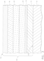
- an exemplary coated substrate 10 that includes a substrate 12, a bond coat layer 14 on the surface 13 of the substrate 12, and a barrier coating 16 on the bond coat layer 14.
- the bond coat layer 14 and the barrier coating 16 form the EBC system 18 of the coated substrate 10.
- the barrier coating 16 includes any compound of having formula Ln 2 ABO 8 as discussed in greater detail above.
- the substrate includes, in one embodiment, a ceramic matrix composite (CMC) material.
- CMCs refers to silicon-containing, or oxide-oxide, matrix and reinforcing materials.
- Some examples of CMCs acceptable for use herein can include, but are not limited to, materials having a matrix and reinforcing fibers comprising non-oxide silicon-based materials such as silicon carbide, silicon nitride, silicon oxycarbides, silicon oxynitrides, and mixtures thereof. Examples include, but are not limited to, CMCs with silicon carbide matrix and silicon carbide fiber; silicon nitride matrix and silicon carbide fiber; and silicon carbide/silicon nitride matrix mixture and silicon carbide fiber.
- CMCs can have a matrix and reinforcing fibers comprised of oxide ceramics. These oxide-oxide composites are described below.
- the oxide-oxide CMCs may be comprised of a matrix and reinforcing fibers comprising oxide-based materials such as aluminum oxide (Al 2 O 3 ), silicon dioxide (SiO 2 ), aluminosilicates, and mixtures thereof.
- oxide-based materials such as aluminum oxide (Al 2 O 3 ), silicon dioxide (SiO 2 ), aluminosilicates, and mixtures thereof.
- Aluminosilicates can include crystalline materials such as mullite (3Al 2 O 3 2SiO 2 ), as well as glassy aluminosilicates.
- monolithic ceramics refers to materials comprising only silicon carbide, only silicon nitride, only alumina, only silica, or only mullite.
- CMCs and monolithic ceramics are collectively referred to as “ceramics.”
- the coating can serve as an environmental barrier coating ("EBC") on such CMCs.
- EBC environmental barrier coating
- the EBCs herein may be suitable for use on ceramic substrate components found in high temperature environments, such as those present in gas turbine engines, for example, combustor components, turbine blades, shrouds, nozzles, heat shields, and vanes.
- the barrier coating 16 that includes the compound of Ln 2 ABO 8 can be used as a single EBC layer (i.e., without any other ECB layers present) on the bond coat layer 14, such as silicon metal or silicon metal layer with silicon oxide thermally grown oxide
- TGO TGO
- This single EBC layer can be realized due to the ability of the compound of Ln 2 ABO 8 to remain dense and crack free during high temperature applications due to the CTE near matching of the barrier coating 16 with the substrate 12.
- the barrier coating 16 is also CMAS resistant and recession resistant, since it readily forms surface Ln 2 AO 5 if the B site volatilizes.
- the Ln 2 AO 5 can be deliberately deposited on top of the Ln 2 ABO 8 as an outer layer 24.
- the barrier coating 16 can be included as a layer within any EBC system on a CMC substrate.
- an optional silica layer 15 may be present on the bond coat layer 14 and positioned between the bond coat layer 14 and the barrier coating 16.
- the silica layer 15 may be applied to the bond coat layer 14, or alternately, may be formed naturally or intentionally on the bond coat layer 14.
- a hermetic layer 20 may optionally be present in the EBC system 18, such as shown in the exemplary coated substrates 10 of Figs. 2 and 3 .
- the hermetic layer 20 may include rare earth disilicates, mullite, barium strontium aluminosilicate (BSAS) and/or combinations thereof.
- BSAS barium strontium aluminosilicate
- an optional transition layer 22 may be present in the EBC system 18, as shown in Figs. 2 and 3 .
- the transition layer may comprise rare earth elements (Ln), rare earth oxides, zirconia, hafnia, hafnia partially or fully stabilized with alkaline earth or rare earth elements, zirconia partially or fully stabilized with alkaline earth or rare earth elements, rare earth hafnates, rare earth zirconates, rare earth monosilicates, alumina, cordierite, and/or combinations thereof.
- Such a transition layer 22 prevents reaction between adjacent layers in an EBC system stack, may provide limited to no protection against penetration of high temperature water vapor, and may or may not have CMAS mitigation capability.
- the barrier coating 16 including a compound of the formula Ln 2 ABO 8 can also offer superior resistance against CMAS if it is deposited on top of another EBC layer, such as the hermetic layer 20 (e.g., a hermetic layer 20 including Yb 2 Si 2 O 7 ), transition layer 22 (e.g. HfO 2 ), or combinations thereof.
- the hermetic layer 20 e.g., a hermetic layer 20 including Yb 2 Si 2 O 7
- transition layer 22 e.g. HfO 2
- the barrier coating 16 defines an external surface 17 of the EBC system similar to the embodiment shown in Fig. 1 .
- the exposed barrier coating 16 can additionally serve as an abradable layer on the EBC system 18 and the CMC substrate 12.
- an optional outer coat layer 24 and optional abradable layer 26 can be present on the barrier coating 16.
- Such an outer coat layer 24 can be Ln 2 AO 5
- the abradable layer 26, can be BSAS or rare earth disilicate (e.g. ytterbium disilicate or Yb 2 Si 2 O 7 ) where the abradable layer is the outermost layer.
- the particular embodiment shown in Fig. 4 has a EBC system 18 that includes a bond coat layer 14 (e.g., of silicon) on the substrate 12 (e.g., a SiC CMC substrate), a barrier coating 16 (e.g., Ln 2 Si y A 1-y Mo x W 1-x O 8 as discussed above), and an outer coat layer 24 (e.g., Ln 2 SiO 5 as discussed above, such as Y 2 SiO 5 ).
- a bond coat layer 14 e.g., of silicon
- the substrate 12 e.g., a SiC CMC substrate
- a barrier coating 16 e.g., Ln 2 Si y A 1-y Mo x W 1-x O 8 as discussed above
- an outer coat layer 24 e.g., Ln 2 SiO 5 as discussed above, such as Y 2 SiO 5
- Other layers could be included in this exemplary EBC system, as discussed herein.
- the coated substrate can be utilized as a turbine component for a gas turbine.
- the turbine component can be a CMC component positioned within a hot gas flow path of the gas turbine such that the coating forms an environmental barrier coating on the component to protect the component within the gas turbine when exposed to the hot gas flow path.
- the substrate includes a superalloy material, such as a nickel-based superalloy, a cobalt-based superalloy, a titanium-based superalloy, or an iron-based superalloy.
- the coating which includes the compound of Ln 2 ABO 8 as discussed above, can serve as a thermal barrier coating ("TBC") on such superalloys.
- TBC thermal barrier coating
- the TBCs herein may be suitable for use on superalloy substrate components found in high temperature environments, such as those present in gas turbine engines, for example, combustor components, turbine blades, shrouds, nozzles, heat shields, and vanes.
- the barrier coating 16 that includes the compound of Ln 2 ABO 8 can be used as a single TBC layer (i.e., without any other TBC layers present) on the superalloy material.
- the barrier coating 16 is also CMAS resistant and recession resistant, since it readily forms surface Ln 2 AO 5 if the B site volatilizes.
- a bond coat layer 14 can be present between the metal substrate and barrier coating 16.
- the bond coat can include materials that form an aluminum oxide thermally grown oxide (TGO) such as platinum and other noble metal aluminides (e.g., an aluminide including ruthenium, rhodium, palladium, silver, osmium, iridium, platinum, gold, or mixtures thereof), nickel aluminide, and MCrAlY's (where M is nickel, cobalt, iron, or combinations thereof), or can include materials that form a silicon oxide TGO such as metal silicides (e.g. molybdenum silicide, iron silicide, etc.).
- TGO aluminum oxide thermally grown oxide
- platinum and other noble metal aluminides e.g., an aluminide including ruthenium, rhodium, palladium, silver, osmium, iridium, platinum, gold, or mixtures thereof
- nickel aluminide e.g., nickel osmium, iridium, platinum, gold
- the barrier coating 16 can be included as a layer within any TBC system on an alloy substrate.
- an optional oxide layer 15 e.g., silicon oxide, aluminum oxide, and/or zinc oxide, optionally with a transition metal present as a stabilizer, such as yttria
- the oxide layer 15 may be applied to the bond coat layer 14, or alternately, may be formed naturally or intentionally on the bond coat layer 14.
- an optional TBC layer 22 and/or optional TBC layer 24 may be present in the TBC system 18, as shown in Figs. 2 and 3 .
- the optional TBC layer may comprise rare earth elements (Ln), rare earth oxides, rare earth gallates, rare earth aluminates, rare earth iron oxides, hafnia partially or fully stabilized with alkaline earth or rare earth elements, zirconia partially or fully stabilized with alkaline earth or rare earth elements, rare earth hafnates, rare earth zirconates, rare earth monosilicates, and/or combinations thereof.
- Such optional TBC layers may be positional beneath (optional TBC layer 22), at an outer location in relation to layer 16 (optional TBC layer 24), or as a combination.
- the barrier coating 16 including a compound of the formula Ln 2 ABO 8 can also offer superior resistance against CMAS if it is deposited on top of an optional TBC layer 22 (e.g., zirconia partially or fully stabilized with rare earth elements).
- the optional TBC layer 22 may also prevent reaction between barrier coating 16 and the alloy substrate 12, bond coat 14, or bond coat TGO 15.
- the barrier coating 16 defines an external surface 17 of the TBC system similar to the embodiment shown in Fig. 1 .
- the exposed barrier coating 16 can additionally serve as an abradable layer on the TBC system 18 and the alloy substrate 12.
- the particular embodiment shown in Fig. 5 has a TBC system 18 that includes a bond coat layer 14 (e.g., of Pt aluminide) on the substrate 12 (e.g., a superalloy substrate), an oxide layer 15 (e.g., comprising yttria stabilized ZrO 2 ) on the bond coat layer 14, and a barrier coating 16 (e.g., Ln 2 ABO 8 as discussed above).
- a bond coat layer 14 e.g., of Pt aluminide
- oxide layer 15 e.g., comprising yttria stabilized ZrO 2
- barrier coating 16 e.g., Ln 2 ABO 8 as discussed above.
- Other layers could be included in this exemplary TBC system, as discussed herein.
- an optional TBC layer 24 and optional abradable layer 26 can be present on the barrier coating 16.
- the optional abradable layer 26 may comprise Ln 2 ABO 8 , any of the optional TBC layer 24 materials described above, or combinations thereof.
- the coated substrate can be utilized as a turbine component for a gas turbine.
- the turbine component can be a superalloy component positioned within a hot gas flow path of the gas turbine such that the coating forms a thermal barrier coating on the component to protect the component within the gas turbine when exposed to the hot gas flow path.
- the compound of the formula: Ln 2 ABO 8 can also be utilized as an abradable coating forming the external, exposed surface of any type of TBC or EBC system on a substrate.
- the abradable coating can be formed from a single layer or from multiple layers.
- embodiments of the abradable layer 26 may include a continuous dense layer (e.g., less than about 15% porosity), a continuous porous layer (e.g., greater than about 15% porosity), and/or a pattern of dense (e.g., less than about 15% porosity) abradable ridges.
- an exemplary embodiment is shown having a EBC or TBC system 18 on a substrate 12, and an abradable coating 26 on the EBC or TBC system 18.
- the abradable coating 26 defines an external surface that is configured to be abraded upon contact with another component, effectively protecting the underlying EBC or TBC system 18.
- the use of the compound of the formula: Ln 2 ABO 8 discussed above, can further add barrier properties to the EBC or TBC system 18 as well as tailoring the CTE to the particular EBC or TBC system 18 and/or substrate 12.
- the EBC system 18 can include a bond coat layer (e.g., of silicon), a hermetic layer (e.g., including a rare earth disilicate), a transition layer (e.g., Ln 2 SiO 5 as discussed above, such as Y 2 SiO 5 ), and the abradable layer 26 comprising compound of the formula: Ln 2 ABO 8 .
- a EBC layer e.g., comprising BSAS
- an additional hermetic layer e.g., comprising a rare earth disilicate
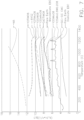
- Fig. 7 shows the CTE of various exemplary Ln 2 ABO 8 compounds compared to a superalloy material (commercially available under the trade designation N5 from General Electric Company); a CMC material (SiC-SiC CMC); a known rare earth monosilicate EBC material; and another known rare earth monosilicate EBC material; and a known TBC layer (8YSZ).
- a superalloy material commercially available under the trade designation N5 from General Electric Company
- a CMC material SiC-SiC CMC
- a known rare earth monosilicate EBC material and another known rare earth monosilicate EBC material
- TBC layer (8YSZ 8YSZ
- the use of the larger, W led to an increased CTE in the Ln 2 ABO 8 compound on the "B" position as compared to Mo.
- the inverse is true for the Ln site, where the smaller Ln elements led to an increased CTE in the Ln 2 ABO 8 compound.
- the CTE of the material can be tailored towards that of a coating for SiC CMC's (with lower CTE) or for nickel-based superalloys (with higher CTE).
Landscapes
- Chemical & Material Sciences (AREA)
- Engineering & Computer Science (AREA)
- Ceramic Engineering (AREA)
- Organic Chemistry (AREA)
- Materials Engineering (AREA)
- Inorganic Chemistry (AREA)
- Structural Engineering (AREA)
- Mechanical Engineering (AREA)
- Chemical Kinetics & Catalysis (AREA)
- Metallurgy (AREA)
- General Engineering & Computer Science (AREA)
- Turbine Rotor Nozzle Sealing (AREA)
- Manufacturing & Machinery (AREA)
- Other Surface Treatments For Metallic Materials (AREA)
Abstract
Description
- The present application claims priority to
U.S. Provisional Patent Application Serial No. 62/018,983 titled "Thermal and Environmental Barrier Coating Compositions and Methods of Deposition" of Kirby, et al. filed on June 30, 2014 U.S. Provisional Patent Application Serial No. 62/069,346 titled "Thermal And Environmental Barrier Coating Compositions And Methods Of Deposition" of Kirby, et al. filed on 28 October 2014 - Embodiments of the present invention generally relate to thermal and environmental barrier coatings for ceramic components and/or metallic components, along with methods of making the same.
- Higher operating temperatures for gas turbine engines are continuously being sought in order to improve their efficiency. However, as operating temperatures increase, the high temperature durability of the components of the engine must correspondingly increase. Significant advances in high temperature capabilities have been achieved through the formulation of iron, nickel, and cobalt-based superalloys. Still, with many hot gas path components constructed from supper alloys, thermal barrier coatings (TBCs) can be utilized to insulate the components and can sustain an appreciable temperature difference between the load-bearing alloys and the coating surface, thus limiting the thermal exposure of the structural component.
- While superalloys have found wide use for components used throughout gas turbine engines, and especially in the higher temperature sections, alternative lighter-weight substrate materials have been proposed, such as ceramic matrix composite (CMC) materials. CMC and monolithic ceramic components can be coated with environmental barrier coatings (EBCs) to protect them from the harsh environment of high temperature engine sections. EBCs can provide a dense, hermetic seal against the corrosive gases in the hot combustion environment. In dry, high temperature environments, silicon-based (nonoxide) CMCs and monolithic ceramics undergo oxidation to form a protective silicon oxide scale. However, the silicon oxide reacts rapidly with high temperature steam, such as found in gas turbine engines, to form volatile silicon species. This oxidation/volatilization process can result in significant material loss, or recession, over the lifetime of an engine component. This recession also occurs in CMC and monolithic ceramic components comprising aluminum oxide, as aluminum oxide reacts with high temperature steam to form volatile aluminum species as well.
- Currently, most EBCs used for CMC and monolithic ceramic components consist of a three-layer coating system generally including a bond coat layer, at least one transition layer applied to the bond coat layer, and an optional outer layer applied to the transition layer. Optionally, a silica layer may be present between the bond coat layer and the adjacent transition layer. Together these layers can provide environmental protection for the CMC or monolithic ceramic component.
- More specifically, the bond coat layer may comprise silicon and may generally have a thickness of from about 0.5 mils (about 12.7 µm) to about 6 mils (about 152 µm). For silicon-based nonoxide CMCs and monolithic ceramics, the bond coat layer serves as an oxidation barrier to prevent oxidation of the substrate. The silica layer may be applied to the bond coat layer, or alternately, may be formed naturally or intentionally on the bond coat layer. The transition layer may typically comprise mullite, barium strontium aluminosilicate (BSAS), and various combinations thereof, while the optional outer layer may comprise BSAS. There may be from 1 to 3 transition layers present, each layer having a thickness of from about 0.1 mils (about 2.5 µm) to about 6 mils (about 152 µm), and the optional outer layer may have a thickness of from about 0.1 mils (about 2.5 µm) to about 40 mils (about 1 mm).
- Each of the transition and outer layers can have differing porosity. At a porosity of about 10% or less, the layer is a hermetic seal to the hot gases in the combustion environment. From about 10% to about 40% porosity, the layer can display mechanical integrity, but hot gases can penetrate through the coating layer damaging the underlying EBC. While it is necessary for at least one of the transition layer or outer layer to be hermetic, it can be beneficial to have some layers of higher porosity range to mitigate mechanical stress induced by any thermal expansion mismatch between the coating materials and the substrate.
- Unfortunately, deposits of calcium-magnesium-alumino-silicate (CMAS) have been observed to form on components located within higher temperature sections of gas turbine engines, particularly in combustor and turbine sections. These CMAS deposits have been shown to have a detrimental effect on the life of thermal barrier coatings, and it is known that BSAS and CMAS chemically interact at high temperatures, i.e. above the melting point of CMAS (approximately 1150 °C. to 1650 °C.). It is also known that the reaction byproducts formed by the interaction of BSAS and CMAS can be detrimental to EBCs, as well as susceptible to volatilization in the presence of steam at high temperatures. Such volatilization can result in the loss of coating material and protection for the underlying component. Thus, it is expected that the presence of CMAS will interact with the EBC, thereby jeopardizing the performance of the component along with component life. Accordingly, there remains a need for methods for making EBCs and ceramic components that is CMAS resistant and recession resistant.
- Aspects and advantages of the invention will be set forth in part in the following description, or may be obvious from the description, or may be learned through practice of the invention.
- A coated substrate is generally provided that comprises: a substrate; and a barrier coating comprising a compound having the formula: Ln2ABO8, where Ln comprises scandium, yttrium, lanthanum, cerium, praseodymium, neodymium, promethium, samarium, europium, gadolinium, terbium, dysprosium, holmium, erbium, thulium, ytterbium, lutetium, or mixtures thereof; A comprises Si, Ti, Ge, Sn, Ce, Hf, Zr, or a combination thereof; and B comprises Mo, W, or a combination thereof. In one embodiment, B comprises Mo.
- A gas turbine is also generally provided that comprises the coated substrate described above. In one embodiment, the coated substrate defines a turbine component positioned within a hot gas flow path of the gas turbine such that the coating forms a barrier coating on the component to protect the component within the gas turbine when exposed to the hot gas flow path.
- These and other features, aspects and advantages of the present invention will become better understood with reference to the following description and appended claims. The accompanying drawings, which are incorporated in and constitute a part of this specification, illustrate embodiments of the invention and, together with the description, serve to explain the principles of the invention.
- The subject matter which is regarded as the invention is particularly pointed out and distinctly claimed in the concluding part of the specification. The invention, however, may be best understood by reference to the following description taken in conjunction with the accompanying drawing figures in which:
-
FIG. 1 is a schematic cross sectional view of an exemplary coated substrate in accordance with one embodiment disclosed herein; -
FIG. 2 is a schematic cross sectional view of another exemplary coated substrate in accordance with one embodiment disclosed herein; -
FIG. 3 is a schematic cross sectional view of yet another exemplary coated substrate in accordance with one embodiment disclosed herein; -
FIG. 4 is a schematic cross sectional view of still another exemplary coated substrate in accordance with one embodiment disclosed herein; -
FIG. 5 is a schematic cross sectional view of still another exemplary coated substrate in accordance with one embodiment disclosed herein; -
FIG. 6 is a schematic cross sectional view of still another exemplary coated substrate in accordance with one embodiment disclosed herein; and -
FIG. 7 shows the CTE curve of various exemplary Ln2ABO8 compounds compared to a superalloy material (N5). - Repeat use of reference characters in the present specification and drawings is intended to represent the same or analogous features or elements of the present invention.
- Reference now will be made in detail to embodiments of the invention, one or more examples of which are illustrated in the drawings. Each example is provided by way of explanation of the invention, not limitation of the invention. In fact, it will be apparent to those skilled in the art that various modifications and variations can be made in the present invention without departing from the scope or spirit of the invention. For instance, features illustrated or described as part of one embodiment can be used with another embodiment to yield a still further embodiment. Thus, it is intended that the present invention covers such modifications and variations as come within the scope of the appended claims and their equivalents.
- In the present disclosure, when a layer is being described as "on" or "over" another layer or substrate, it is to be understood that the layers can either be directly contacting each other or have another layer or feature between the layers, unless expressly stated to the contrary. Thus, these terms are simply describing the relative position of the layers to each other and do not necessarily mean "on top of" since the relative position above or below depends upon the orientation of the device to the viewer.
- Chemical elements are discussed in the present disclosure using their common chemical abbreviation, such as commonly found on a periodic table of elements. For example, hydrogen is represented by its common chemical abbreviation H; helium is represented by its common chemical abbreviation He; and so forth.
- Substrates are generally provided that have a coating comprising a compound of the formula: Ln2ABO8, where Ln comprises a rare earth element or a mixture of rare earth elements; A comprises Si, Ti, Ge, Sn, Ce (e.g., Ce4+), Hf, Zr, or a combination thereof; and B comprises Mo, W, or a combination thereof. The compound has, in one embodiment, a zircon crystal structure within the coating. For example, the coating can have a single phase structure (e.g., a zircon crystal structure or a scheelite crystal structure) with less than about 10% by volume of a secondary crystal phase.
- "Ln" refers to the rare earth elements of scandium (Sc), yttrium (Y), lanthanum (La), cerium (Ce), praseodymium (Pr), neodymium (Nd), promethium (Pm), samarium (Sm), europium (Eu), gadolinium (Gd), terbium (Tb), dysprosium (Dy), holmium (Ho), erbium (Er), thulium (Tm), ytterbium (Yb), lutetium (Lu), or mixtures thereof. In particular embodiments, Ln is selected from the group consisting of neodymium, gadolinium, erbium, yttrium, and mixtures thereof.
- In one embodiment, B comprises Mo. In certain embodiments, B comprises a combination of Mo and W. For instance, the compound can have the formula Ln2AMoxW1-xO8, where 0 ≤ x ≤ about 0.5 (e.g., about 0.1 ≤ x ≤ about 0.5).
- While compounds of the formula Ln2ABO8 exhibit high stability in high temperature steam such as found in a hot gas path of a gas turbine, the most unstable element in the compound is on the B site (i.e., Mo and/or W). However, even if some Mo or W volatilizes, the result may be a Ln2AO5 compound on the surface that is also very resistant to high temperature steam recession. Thus, in one embodiment, the material at the Ln site can be chosen to such that a mixture of oxyapetite phase and Ln2AO5 phase forms on the surface of the coating. This reaction seals the material from deep penetration of the molten aluminosilicate into the EBC system. Also, the presence of the Ln2AO5 component in the Ln2ABO8 molten aluminosilicate reaction layer improves adhesion since the Ln2AO5 has a lower thermal expansion than the oxyapatite; resulting in a net thermal expansion that is closer to the thermal expansion of the substrate. Furthermore, both the Ln2AO5 and oxyapatite phases that result from reaction between molten aluminosilicate and a layer including Ln2ABO8 are resistant to high temperature steam recession.
- While A can be any of Si, Ti, Ge, Sn, Ce, Hf, Zr, or a combination thereof, in one particular embodiment, A includes Si, either alone or in combination with Ti, Sn, Ce, Ge, Hf, and/or Zr. For example, the compound can have the formula: Ln2SiyA1-yMoxW1-xO8, where 0 ≤ x ≤ about 0.5; 0 < y ≤ about 0.5; and A is Ti, Ge, Sn, Ce, Hf, Zr, or a combination thereof. In certain embodiments, A can be Hf and/or Zr, either alone or in combination with Ti, Sn, Ce, Ge, and/or Si, since the presence of Hf and/or Zr has a significant effect on raising the melting point of the compound.
- The selection of the components in the compound for use in the coating can generally be selected to ensure the single phase crystal structure (e.g., zircon structure) and to match closely the coefficient of thermal expansion ("CTE") of the substrate. CTE matching (or a near match) can enable the formation and operation of a dense, crack free coating layer on the substrate's surface to ensure that high temperature water vapor does not penetrate to the underlying substrate. For example, if the substrate is a CMC that includes silicon carbide, then a coating that includes the compound having the formula: Y2SiMoO8 can be particularly suitable due to the close CTEs of SiC and Y2SiMoO8. Thus, a preferred embodiment of the compound can have the formula: Ln2SiyA1-yMoxW1-xO8, where 0 ≤ x ≤ about 0. 5; 0 < y ≤ about 0.5; and A is Ti, Ge, Sn, Ce, Hf, Zr, or a combination thereof, especially when the compound has a zircon crystal structure.
- Many of the other compounds of the Ln2ABO8 have a scheelite structure that may have a thermal expansion nearly equivalent to a SiC CMC or a higher thermal expansion than a SiC CMC. If higher than a SiC, however, vertically cracked layers comprised of the scheelite formed of these materials can still offer some resistance to high T steam, particularly if there are additional layers underneath that are crack free to act as a hermetic layer. In addition, the compounds of the formula Ln2ABO8 (either with zircon or scheelite structure) offer protection from molten aluminosilicates, particularly those comprising dirt or sand. That is, the coating is resistant to molten aluminosilicates themselves, such that the coating layer remains hermetic despite reaction with molten aluminosilicates.
- Without wishing to be bound by any particular theory, it is believed that the CTE of the Ln2ABO8 compound can be controlled by altering the size of the element(s) represented by "A" in the formula. That is, through intentional use of Si, Ti, Ge, Sn, Ce, Hf, Zr, or a combination thereof in the Ln2ABO8 compound, the CTE of the resulting coating can be controlled. More particularly, it is believed that increasing the ionic size of the element(s) at position represented by "A" in the formula can lead to an increased CTE in the coating. This feature is discussed in greater detail below in the Example section.
- Such a coating can be included as a stand-along coating layer (with or without a bond layer present) on a substrate, within any layer of an EBC system on a substrate, and/or as an abradable layer on an EBC system.
- Referring to
Fig. 1 , for example, an exemplarycoated substrate 10 is shown that includes asubstrate 12, abond coat layer 14 on thesurface 13 of thesubstrate 12, and abarrier coating 16 on thebond coat layer 14. Collectively, thebond coat layer 14 and thebarrier coating 16 form theEBC system 18 of thecoated substrate 10. In this embodiment, thebarrier coating 16 includes any compound of having formula Ln2ABO8 as discussed in greater detail above. I. CMC Substrates - The substrate includes, in one embodiment, a ceramic matrix composite (CMC) material. As used herein, "CMCs" refers to silicon-containing, or oxide-oxide, matrix and reinforcing materials. Some examples of CMCs acceptable for use herein can include, but are not limited to, materials having a matrix and reinforcing fibers comprising non-oxide silicon-based materials such as silicon carbide, silicon nitride, silicon oxycarbides, silicon oxynitrides, and mixtures thereof. Examples include, but are not limited to, CMCs with silicon carbide matrix and silicon carbide fiber; silicon nitride matrix and silicon carbide fiber; and silicon carbide/silicon nitride matrix mixture and silicon carbide fiber. Furthermore, CMCs can have a matrix and reinforcing fibers comprised of oxide ceramics. These oxide-oxide composites are described below.
- Specifically, the oxide-oxide CMCs may be comprised of a matrix and reinforcing fibers comprising oxide-based materials such as aluminum oxide (Al2O3), silicon dioxide (SiO2), aluminosilicates, and mixtures thereof. Aluminosilicates can include crystalline materials such as mullite (3Al2O3 2SiO2), as well as glassy aluminosilicates.
- As used herein, "monolithic ceramics" refers to materials comprising only silicon carbide, only silicon nitride, only alumina, only silica, or only mullite. Herein, CMCs and monolithic ceramics are collectively referred to as "ceramics."
- The coating can serve as an environmental barrier coating ("EBC") on such CMCs. For example, the EBCs herein may be suitable for use on ceramic substrate components found in high temperature environments, such as those present in gas turbine engines, for example, combustor components, turbine blades, shrouds, nozzles, heat shields, and vanes.
- As shown in
Fig. 1 , thebarrier coating 16 that includes the compound of Ln2ABO8 can be used as a single EBC layer (i.e., without any other ECB layers present) on thebond coat layer 14, such as silicon metal or silicon metal layer with silicon oxide thermally grown oxide - (TGO). This single EBC layer can be realized due to the ability of the compound of Ln2ABO8 to remain dense and crack free during high temperature applications due to the CTE near matching of the
barrier coating 16 with thesubstrate 12. Thebarrier coating 16 is also CMAS resistant and recession resistant, since it readily forms surface Ln2AO5 if the B site volatilizes. - Instead of allowing the Ln2AO5 to form in situ, in another embodiment, it can be deliberately deposited on top of the Ln2ABO8 as an
outer layer 24. - Alternatively, the
barrier coating 16 can be included as a layer within any EBC system on a CMC substrate. The embodiments shown inFigs. 2 and3 depictexemplary EBC systems 18 that include thebarrier coating 16 therein. For example, anoptional silica layer 15 may be present on thebond coat layer 14 and positioned between thebond coat layer 14 and thebarrier coating 16. Thesilica layer 15 may be applied to thebond coat layer 14, or alternately, may be formed naturally or intentionally on thebond coat layer 14. - A hermetic layer 20 (i.e., a layer that) may optionally be present in the
EBC system 18, such as shown in the exemplarycoated substrates 10 ofFigs. 2 and3 . If present, thehermetic layer 20 may include rare earth disilicates, mullite, barium strontium aluminosilicate (BSAS) and/or combinations thereof. Such ahermetic layer 20 prevents penetration of high temperature water vapor but may have limited to no CMAS mitigation capability. - Additionally or alternatively, an
optional transition layer 22 may be present in theEBC system 18, as shown inFigs. 2 and3 . The transition layer may comprise rare earth elements (Ln), rare earth oxides, zirconia, hafnia, hafnia partially or fully stabilized with alkaline earth or rare earth elements, zirconia partially or fully stabilized with alkaline earth or rare earth elements, rare earth hafnates, rare earth zirconates, rare earth monosilicates, alumina, cordierite, and/or combinations thereof. Such atransition layer 22 prevents reaction between adjacent layers in an EBC system stack, may provide limited to no protection against penetration of high temperature water vapor, and may or may not have CMAS mitigation capability. - In such embodiments, the
barrier coating 16 including a compound of the formula Ln2ABO8 (either zircon or scheelte) can also offer superior resistance against CMAS if it is deposited on top of another EBC layer, such as the hermetic layer 20 (e.g., ahermetic layer 20 including Yb2Si2O7), transition layer 22 (e.g. HfO2), or combinations thereof. - In the exemplary
coated substrate 10 ofFig. 2 , thebarrier coating 16 defines anexternal surface 17 of the EBC system similar to the embodiment shown inFig. 1 . In such an embodiment, the exposedbarrier coating 16 can additionally serve as an abradable layer on theEBC system 18 and theCMC substrate 12. - However, in the embodiment shown in
Fig. 3 , an optionalouter coat layer 24 and optionalabradable layer 26 can be present on thebarrier coating 16. Such anouter coat layer 24 can be Ln2AO5, and theabradable layer 26, can be BSAS or rare earth disilicate (e.g. ytterbium disilicate or Yb2Si2O7) where the abradable layer is the outermost layer. - For example, the particular embodiment shown in
Fig. 4 has aEBC system 18 that includes a bond coat layer 14 (e.g., of silicon) on the substrate 12 (e.g., a SiC CMC substrate), a barrier coating 16 (e.g., Ln2SiyA1-yMoxW1-xO8 as discussed above), and an outer coat layer 24 (e.g., Ln2SiO5 as discussed above, such as Y2SiO5). Other layers could be included in this exemplary EBC system, as discussed herein. - As stated, the coated substrate can be utilized as a turbine component for a gas turbine. In particular, the turbine component can be a CMC component positioned within a hot gas flow path of the gas turbine such that the coating forms an environmental barrier coating on the component to protect the component within the gas turbine when exposed to the hot gas flow path.
- In other embodiments, the substrate includes a superalloy material, such as a nickel-based superalloy, a cobalt-based superalloy, a titanium-based superalloy, or an iron-based superalloy. The coating, which includes the compound of Ln2ABO8 as discussed above, can serve as a thermal barrier coating ("TBC") on such superalloys. For example, the TBCs herein may be suitable for use on superalloy substrate components found in high temperature environments, such as those present in gas turbine engines, for example, combustor components, turbine blades, shrouds, nozzles, heat shields, and vanes.
- Referring again to
Fig. 1 , thebarrier coating 16 that includes the compound of Ln2ABO8 can be used as a single TBC layer (i.e., without any other TBC layers present) on the superalloy material. Thebarrier coating 16 is also CMAS resistant and recession resistant, since it readily forms surface Ln2AO5 if the B site volatilizes. Alternatively, abond coat layer 14 can be present between the metal substrate andbarrier coating 16. The bond coat can include materials that form an aluminum oxide thermally grown oxide (TGO) such as platinum and other noble metal aluminides (e.g., an aluminide including ruthenium, rhodium, palladium, silver, osmium, iridium, platinum, gold, or mixtures thereof), nickel aluminide, and MCrAlY's (where M is nickel, cobalt, iron, or combinations thereof), or can include materials that form a silicon oxide TGO such as metal silicides (e.g. molybdenum silicide, iron silicide, etc.). - Alternatively, the
barrier coating 16 can be included as a layer within any TBC system on an alloy substrate. Referring to the embodiments shown inFigs. 2 and3 , an optional oxide layer 15 (e.g., silicon oxide, aluminum oxide, and/or zinc oxide, optionally with a transition metal present as a stabilizer, such as yttria) may be present on thebond coat layer 14 and positioned between thebond coat layer 14 and thebarrier coating 16. Theoxide layer 15 may be applied to thebond coat layer 14, or alternately, may be formed naturally or intentionally on thebond coat layer 14. - Additionally or alternatively, an
optional TBC layer 22 and/oroptional TBC layer 24 may be present in theTBC system 18, as shown inFigs. 2 and3 . The optional TBC layer may comprise rare earth elements (Ln), rare earth oxides, rare earth gallates, rare earth aluminates, rare earth iron oxides, hafnia partially or fully stabilized with alkaline earth or rare earth elements, zirconia partially or fully stabilized with alkaline earth or rare earth elements, rare earth hafnates, rare earth zirconates, rare earth monosilicates, and/or combinations thereof. Such optional TBC layers may be positional beneath (optional TBC layer 22), at an outer location in relation to layer 16 (optional TBC layer 24), or as a combination. - In such an embodiment, the
barrier coating 16 including a compound of the formula Ln2ABO8 (either zircon or scheelite) can also offer superior resistance against CMAS if it is deposited on top of an optional TBC layer 22 (e.g., zirconia partially or fully stabilized with rare earth elements). In such case, theoptional TBC layer 22 may also prevent reaction betweenbarrier coating 16 and thealloy substrate 12,bond coat 14, orbond coat TGO 15. - In the exemplary
coated substrate 10 ofFig. 2 , thebarrier coating 16 defines anexternal surface 17 of the TBC system similar to the embodiment shown inFig. 1 . In such an embodiment, the exposedbarrier coating 16 can additionally serve as an abradable layer on theTBC system 18 and thealloy substrate 12. - For example, the particular embodiment shown in
Fig. 5 has aTBC system 18 that includes a bond coat layer 14 (e.g., of Pt aluminide) on the substrate 12 (e.g., a superalloy substrate), an oxide layer 15 (e.g., comprising yttria stabilized ZrO2) on thebond coat layer 14, and a barrier coating 16 (e.g., Ln2ABO8 as discussed above). Other layers could be included in this exemplary TBC system, as discussed herein. - However, in the embodiment shown in
Fig. 3 , anoptional TBC layer 24 and optionalabradable layer 26 can be present on thebarrier coating 16. The optionalabradable layer 26 may comprise Ln2ABO8, any of theoptional TBC layer 24 materials described above, or combinations thereof. - As stated, the coated substrate can be utilized as a turbine component for a gas turbine. In particular, the turbine component can be a superalloy component positioned within a hot gas flow path of the gas turbine such that the coating forms a thermal barrier coating on the component to protect the component within the gas turbine when exposed to the hot gas flow path.
- The compound of the formula: Ln2ABO8, discussed above, can also be utilized as an abradable coating forming the external, exposed surface of any type of TBC or EBC system on a substrate. The abradable coating can be formed from a single layer or from multiple layers. For example, embodiments of the
abradable layer 26 may include a continuous dense layer (e.g., less than about 15% porosity), a continuous porous layer (e.g., greater than about 15% porosity), and/or a pattern of dense (e.g., less than about 15% porosity) abradable ridges. - Referring to
Fig. 6 , an exemplary embodiment is shown having a EBC orTBC system 18 on asubstrate 12, and anabradable coating 26 on the EBC orTBC system 18. Here, theabradable coating 26 defines an external surface that is configured to be abraded upon contact with another component, effectively protecting the underlying EBC orTBC system 18. The use of the compound of the formula: Ln2ABO8, discussed above, can further add barrier properties to the EBC orTBC system 18 as well as tailoring the CTE to the particular EBC orTBC system 18 and/orsubstrate 12. - For instance, if the
substrate 12 is a SiC CMC, then theEBC system 18 can include a bond coat layer (e.g., of silicon), a hermetic layer (e.g., including a rare earth disilicate), a transition layer (e.g., Ln2SiO5 as discussed above, such as Y2SiO5), and theabradable layer 26 comprising compound of the formula: Ln2ABO8. A EBC layer (e.g., comprising BSAS) and/or an additional hermetic layer (e.g., comprising a rare earth disilicate) may also be present in theEBC system 18, such as between the bond coat layer and the hermetic layer. - It is believed that increasing the ionic size of the element(s) at position represented by "A" in the formula can lead to an increased CTE in the coating, without wishing to be bound by any particular theory.
Fig. 7 shows the CTE of various exemplary Ln2ABO8 compounds compared to a superalloy material (commercially available under the trade designation N5 from General Electric Company); a CMC material (SiC-SiC CMC); a known rare earth monosilicate EBC material; and another known rare earth monosilicate EBC material; and a known TBC layer (8YSZ). As shown, the use of larger element(s) at position represented by "A" in the formula generally led to an increased CTE in the Ln2ABO8 compound. Likewise, the use of the larger, W, led to an increased CTE in the Ln2ABO8 compound on the "B" position as compared to Mo. The inverse is true for the Ln site, where the smaller Ln elements led to an increased CTE in the Ln2ABO8 compound. By adjusting the Ln, A, and B elements the CTE of the material can be tailored towards that of a coating for SiC CMC's (with lower CTE) or for nickel-based superalloys (with higher CTE). - While the invention has been described in terms of one or more particular embodiments, it is apparent that other forms could be adopted by one skilled in the art. It is to be understood that the use of "comprising" in conjunction with the coating compositions described herein specifically discloses and includes the embodiments wherein the coating compositions "consist essentially of" the named components (i.e., contain the named components and no other components that significantly adversely affect the basic and novel features disclosed), and embodiments wherein the coating compositions "consist of" the named components (i.e., contain only the named components except for contaminants which are naturally and inevitably present in each of the named components).
This written description uses examples to disclose the invention, including the best mode, and also to enable any person skilled in the art to practice the invention, including making and using any devices or systems and performing any incorporated methods. The patentable scope of the invention is defined by the claims, and may include other examples that occur to those skilled in the art. Such other examples are intended to be within the scope of the claims if they include structural elements that do not differ from the literal language of the claims, or if they include equivalent structural elements with insubstantial differences from the literal languages of the claims.
Further aspects of the invention are provided by the subject matter in the following clauses: - 1. A coated substrate (10), comprising: a substrate (12); and a barrier coating (16) comprising a compound having the formula: Ln2ABO8, where Ln comprises scandium, yttrium, lanthanum, cerium, praseodymium, neodymium, promethium, samarium, europium, gadolinium, terbium, dysprosium, holmium, erbium, thulium, ytterbium, lutetium, or mixtures thereof; A comprises Si, Ti, Ge, Sn, Ce, Hf, Zr, or a combination thereof; and B comprises Mo, W, or a combination thereof.
- 2. The coated substrate (10) as in
clause 1, wherein Ln is selected from the group consisting of scandium (Sc), yttrium (Y), lanthanum (La), cerium (Ce), praseodymium (Pr), neodymium (Nd), promethium (Pm), samarium (Sm), europium (Eu), gadolinium (Gd), terbium (Tb), dysprosium (Dy), holmium (Ho), erbium (Er), thulium (Tm), ytterbium (Yb), lutetium (Lu), and mixtures thereof. - 3. The coated substrate (10) as in
clause 1, wherein Ln comprises yttrium. - 4. The coated substrate (10) as in
clause 1, wherein B comprises Mo. - 5. The coated substrate (10) as in
clause 4, wherein the compound has the formula: Ln2AMoxW1-xO8, where 0 ≤ x ≤ about 0.5. - 6. The coated substrate (10) as in
clause 1, wherein B comprises W or a combination of Mo and W. - 7. The coated substrate (10) as in
clause 6, wherein the compound has the formula: Ln2AMoxW1-xO8, where 0 ≤ x ≤ about 0.5. - 8. The coated substrate (10) as in
clause 7, wherein A comprises Si. - 9. The coated substrate (10) as in clause 8, wherein the compound has the formula: Ln2SiyA1-yMoxW1-xO8, where, 0 ≤ x ≤ about 0.5; 0 < y ≤ about 0.5; and A is Ti, Ge, Sn, Ce, Hf, Zr, or a combination thereof.
- 10. The coated substrate (10) as in
clause 1, wherein the compound has the formula: Y2SiMoO8. - 11. The coated substrate (10) as in
clause 1, wherein A comprises Hf and/or Zr. - 12. The coated substrate (10) as in
clause 1, wherein the compound comprises a zircon crystal structure or a scheelite structure. - 13. The coated substrate (10) as in
clause 1, wherein the substrate (12) comprises a ceramic matrix composite, and wherein the coated substrate (10) further comprises a bond coat layer (14) positioned between the substrate (12) and the barrier coating (16). - 14. The coated substrate (10) as in
clause 13, wherein the bond coat layer (14) comprises silicon, silicon carbide, silicon nitride, molybdenum silicide, rhenium silicide, or combinations thereof. - 15. The coated substrate (10) as in
clause 1, wherein the coated substrate (10) further comprises an outer coat layer (24) on the barrier coating (16), and wherein the outer coat layer (24) comprises Ln2SiO5, where Ln is scandium (Sc), yttrium (Y), lanthanum (La), cerium (Ce), praseodymium (Pr), neodymium (Nd), promethium (Pm), samarium (Sm), europium (Eu), gadolinium (Gd), terbium (Tb), dysprosium (Dy), holmium (Ho), erbium (Er), thulium (Tm), ytterbium (Yb), lutetium (Lu), or mixtures thereof.
Claims (15)
- A coated substrate (10), comprising:a metal substrate (12);a barrier coating (16) comprising a compound having the formula:
Ln2AMoxW1-xO8,
where Ln comprises scandium, yttrium, lanthanum, cerium, praseodymium, neodymium, promethium, samarium, europium, gadolinium, terbium, dysprosium, holmium, erbium, thulium, ytterbium, lutetium, or mixtures thereof;A comprises Si, Ti, Ge, Sn, Ce, Hf, Zr, or a combination thereof; and0 < x ≤ 0.5. - The coated substrate (10) as in claim 1, wherein Ln is selected from the group consisting of scandium (Sc), yttrium (Y), lanthanum (La), cerium (Ce), praseodymium (Pr), neodymium (Nd), promethium (Pm), samarium (Sm), europium (Eu), gadolinium (Gd), terbium (Tb), dysprosium (Dy), holmium (Ho), erbium (Er), thulium (Tm), ytterbium (Yb), lutetium (Lu), and mixtures thereof.
- The coated substrate (10) as in claim 1, wherein Ln comprises yttrium.
- The coated substrate (10) as in claim 1, wherein A comprises Si.
- The coated substrate (10) as in claim 4, wherein the compound has the formula:
Ln2SiyA1-yMoxW1-xO8
where0 < y ≤ 0.5; andA is Ti, Ge, Sn, Ce, Hf, Zr, or a combination thereof. - The coated substrate (10) as in claim 1, wherein A comprises Hf and/or Zr.
- The coated substrate (10) as in claim 1, wherein the compound comprises a zircon crystal structure or a scheelite structure.
- The coated substrate (10) as in claim 1, wherein the metal substrate (12) comprises a nickel-based superalloy, a cobalt-based superalloy, a titanium-based superalloy, or an iron-based superalloy, and wherein the barrier coating defines an external surface of a multi-layer thermal barrier coating system formed on the metal substrate.
- The coated substrate as defined in claim 8, wherein the multi-layer thermal barrier coating system includes an aluminide or silicide bond coat layer on the metal substrate, an oxide layer, and the barrier coating as the outer most layer defining the external surface.
- The coated substrate (10) as in claim 1, further comprising an outer coat layer (24) on the barrier coating (16), and wherein the outer coat layer (24) comprises Ln2SiO5, where Ln is scandium (Sc), yttrium (Y), lanthanum (La), cerium (Ce), praseodymium (Pr), neodymium (Nd), promethium (Pm), samarium (Sm), europium (Eu), gadolinium (Gd), terbium (Tb), dysprosium (Dy), holmium (Ho), erbium (Er), thulium (Tm), ytterbium (Yb), lutetium (Lu), or mixtures thereof.
- The coated substrate as in claim 1, wherein the coated substrate is a component of a gas turbine engine with the barrier coating facing a hot gas stream within the gas turbine engine.
- A gas turbine engine defining a hot gas stream, the gas turbine engine comprising the coated substrate of claim 1, wherein the barrier coating faces the hot gas stream within the gas turbine engine.
- A method of forming a coated substrate, the method comprising:
Applying a barrier coating over a substrate; wherein the barrier coating comprises a compound having the formula:
Ln2AMoxW1-xO8,
where Ln comprises scandium, yttrium, lanthanum, cerium, praseodymium, neodymium, promethium, samarium, europium, gadolinium, terbium, dysprosium, holmium, erbium, thulium, ytterbium, lutetium, or mixtures thereof;A comprises Si, Ti, Ge, Sn, Ce, Hf, Zr, or a combination thereof; and 0 < x ≤ 0.5. - The method of claim 13, wherein the barrier coating is applied to form the external exposed surface of the coated substrate.
- The method of claim 14, wherein the barrier coating is applied as a pattern of dense abradable ridges.
Applications Claiming Priority (4)
| Application Number | Priority Date | Filing Date | Title |
|---|---|---|---|
| US201462018983P | 2014-06-30 | 2014-06-30 | |
| US201462069346P | 2014-10-28 | 2014-10-28 | |
| PCT/US2015/033646 WO2016003571A1 (en) | 2014-06-30 | 2015-06-02 | Thermal and environmental barrier coating compositions |
| EP15733950.8A EP3160920B1 (en) | 2014-06-30 | 2015-06-02 | Barrier coatings |
Related Parent Applications (2)
| Application Number | Title | Priority Date | Filing Date |
|---|---|---|---|
| EP15733950.8A Division-Into EP3160920B1 (en) | 2014-06-30 | 2015-06-02 | Barrier coatings |
| EP15733950.8A Division EP3160920B1 (en) | 2014-06-30 | 2015-06-02 | Barrier coatings |
Publications (2)
| Publication Number | Publication Date |
|---|---|
| EP4194429A1 true EP4194429A1 (en) | 2023-06-14 |
| EP4194429B1 EP4194429B1 (en) | 2026-03-11 |
Family
ID=53502828
Family Applications (2)
| Application Number | Title | Priority Date | Filing Date |
|---|---|---|---|
| EP23154355.4A Active EP4194429B1 (en) | 2014-06-30 | 2015-06-02 | Thermal and environmental barrier coating compositions and methods of deposition |
| EP15733950.8A Active EP3160920B1 (en) | 2014-06-30 | 2015-06-02 | Barrier coatings |
Family Applications After (1)
| Application Number | Title | Priority Date | Filing Date |
|---|---|---|---|
| EP15733950.8A Active EP3160920B1 (en) | 2014-06-30 | 2015-06-02 | Barrier coatings |
Country Status (6)
| Country | Link |
|---|---|
| US (2) | US10421692B2 (en) |
| EP (2) | EP4194429B1 (en) |
| JP (1) | JP6560266B2 (en) |
| CN (1) | CN106660890B (en) |
| CA (1) | CA2952599C (en) |
| WO (1) | WO2016003571A1 (en) |
Families Citing this family (14)
| Publication number | Priority date | Publication date | Assignee | Title |
|---|---|---|---|---|
| US10145252B2 (en) * | 2015-12-09 | 2018-12-04 | General Electric Company | Abradable compositions and methods for CMC shrouds |
| US20170370239A1 (en) * | 2016-06-22 | 2017-12-28 | General Electric Company | Turbine systems with sealing components |
| FR3061710B1 (en) | 2017-01-06 | 2019-05-31 | Safran Ceramics | PART COMPRISING A SUBSTRATE AND AN ENVIRONMENTAL BARRIER |
| FR3067392B1 (en) * | 2017-06-12 | 2020-12-04 | Safran | DOUBLE REACTIVITY ANTI-CMAS COATING |
| FR3071867B1 (en) * | 2017-10-02 | 2020-07-31 | Safran Aircraft Engines | COMPOSITE AUBE WITH CERAMIC MATRIX AND PROCESS FOR MANUFACTURING SUCH A BLADE |
| US10808565B2 (en) * | 2018-05-22 | 2020-10-20 | Rolls-Royce Plc | Tapered abradable coatings |
| CN112654683B (en) * | 2018-09-13 | 2022-09-09 | 住友大阪水泥股份有限公司 | Antifouling film, glass ceramic product, coating for forming antifouling film, and manufacturing method of glass ceramic product |
| US20210198160A1 (en) * | 2018-12-20 | 2021-07-01 | Rolls-Royce High Temperature Composites, Inc. | Dense multi-phase bond coat |
| US11761341B2 (en) | 2021-07-27 | 2023-09-19 | Honeywell International Inc. | Protective coating systems for gas turbine engine applications and methods for fabricating the same |
| WO2023053988A1 (en) | 2021-09-28 | 2023-04-06 | 株式会社カネカ | Polymer and curable composition |
| US12448336B2 (en) * | 2022-02-07 | 2025-10-21 | General Electric Company | Bond coat including metal oxides and oxygen getters |
| EP4488317A4 (en) | 2022-02-28 | 2026-03-11 | Kaneka Corp | METHOD FOR PRODUCING A HOLDING-PROOF RESIN COMPOSITION |
| CN116656359B (en) * | 2023-05-31 | 2024-04-09 | 广西大学 | Tungsten titanate matrix material for rare earth fluorescent powder, fluorescent material and preparation method of fluorescent material |
| CN116656358B (en) * | 2023-05-31 | 2024-04-05 | 广西大学 | A red self-activated tungsten titanate phosphor material and its preparation method and application |
Citations (3)
| Publication number | Priority date | Publication date | Assignee | Title |
|---|---|---|---|---|
| JP2007012508A (en) * | 2005-07-01 | 2007-01-18 | Ushio Inc | Discharge lamp |
| JP2011063452A (en) * | 2009-09-15 | 2011-03-31 | Shinshu Univ | Laminated body and method for manufacturing the same |
| US20130089673A1 (en) * | 2008-12-19 | 2013-04-11 | General Electric Company | Methods for making environmental barrier coatings and ceramic components having cmas mitigation capability |
Family Cites Families (8)
| Publication number | Priority date | Publication date | Assignee | Title |
|---|---|---|---|---|
| US7354651B2 (en) * | 2005-06-13 | 2008-04-08 | General Electric Company | Bond coat for corrosion resistant EBC for silicon-containing substrate and processes for preparing same |
| US8124252B2 (en) * | 2008-11-25 | 2012-02-28 | Rolls-Royce Corporation | Abradable layer including a rare earth silicate |
| US8658255B2 (en) | 2008-12-19 | 2014-02-25 | General Electric Company | Methods for making environmental barrier coatings and ceramic components having CMAS mitigation capability |
| US8501840B2 (en) | 2009-07-31 | 2013-08-06 | General Electric Company | Water based slurry compositions for making environmental barrier coatings and environmental barrier coatings comprising the same |
| US9005716B2 (en) | 2009-07-31 | 2015-04-14 | General Electric Company | Method for making solvent based environmental barrier coatings using sintering aids |
| US20130189531A1 (en) * | 2010-03-29 | 2013-07-25 | Rolls-Royce Corporation | Multilayer cmas-resistant barrier coatings |
| US9945036B2 (en) | 2011-03-22 | 2018-04-17 | General Electric Company | Hot corrosion-resistant coatings and components protected therewith |
| JP2014213272A (en) * | 2013-04-25 | 2014-11-17 | 本田技研工業株式会社 | Exhaust gas purification catalyst and exhaust gas purification device |
-
2015
- 2015-06-02 EP EP23154355.4A patent/EP4194429B1/en active Active
- 2015-06-02 WO PCT/US2015/033646 patent/WO2016003571A1/en not_active Ceased
- 2015-06-02 CN CN201580035987.3A patent/CN106660890B/en active Active
- 2015-06-02 EP EP15733950.8A patent/EP3160920B1/en active Active
- 2015-06-02 US US15/322,837 patent/US10421692B2/en active Active
- 2015-06-02 JP JP2016574377A patent/JP6560266B2/en active Active
- 2015-06-02 CA CA2952599A patent/CA2952599C/en active Active
-
2019
- 2019-08-19 US US16/543,836 patent/US11072566B2/en active Active
Patent Citations (3)
| Publication number | Priority date | Publication date | Assignee | Title |
|---|---|---|---|---|
| JP2007012508A (en) * | 2005-07-01 | 2007-01-18 | Ushio Inc | Discharge lamp |
| US20130089673A1 (en) * | 2008-12-19 | 2013-04-11 | General Electric Company | Methods for making environmental barrier coatings and ceramic components having cmas mitigation capability |
| JP2011063452A (en) * | 2009-09-15 | 2011-03-31 | Shinshu Univ | Laminated body and method for manufacturing the same |
Non-Patent Citations (1)
| Title |
|---|
| HAN X M ET AL: "Sol-gel deposition and luminescence properties of lanthanide ion-doped Y2(1-x)Gd2xSiWO8 (0<=x <=1) phosphor films", APPLIED PHYSICS A; MATERIALS SCIENCE & PROCESSING, SPRINGER, BERLIN, DE, vol. 80, no. 7, 1 April 2005 (2005-04-01), pages 1547 - 1552, XP019336728, ISSN: 1432-0630, DOI: 10.1007/S00339-004-2506-4 * |
Also Published As
| Publication number | Publication date |
|---|---|
| CN106660890A (en) | 2017-05-10 |
| CA2952599A1 (en) | 2016-01-07 |
| CN106660890B (en) | 2020-12-01 |
| US10421692B2 (en) | 2019-09-24 |
| EP3160920A1 (en) | 2017-05-03 |
| US20180194694A1 (en) | 2018-07-12 |
| US11072566B2 (en) | 2021-07-27 |
| US20190367423A1 (en) | 2019-12-05 |
| EP3160920B1 (en) | 2023-03-15 |
| JP2017522254A (en) | 2017-08-10 |
| JP6560266B2 (en) | 2019-08-14 |
| EP4194429B1 (en) | 2026-03-11 |
| CA2952599C (en) | 2023-03-21 |
| WO2016003571A1 (en) | 2016-01-07 |
Similar Documents
| Publication | Publication Date | Title |
|---|---|---|
| US11072566B2 (en) | Thermal and environmental barrier coating compositions and methods of deposition | |
| EP2189504B1 (en) | Reinforced oxide coatings | |
| EP2553027B1 (en) | Multilayer cmas-resistant barrier coating | |
| US10871078B2 (en) | Low porosity abradable coating | |
| JP5067775B2 (en) | Process for producing corrosion-resistant EBC bond coats and the like for silicon-containing substrates | |
| US7442444B2 (en) | Bond coat for silicon-containing substrate for EBC and processes for preparing same | |
| CA2712248C (en) | Cmas-resistant thermal barrier coatings | |
| US7357994B2 (en) | Thermal/environmental barrier coating system for silicon-containing materials | |
| EP2194164B1 (en) | Multilayer thermal barrier coatings | |
| JP2006347871A (en) | Process for producing anti-corrosion sealants and the like for silicon-containing substrates | |
| US11655543B2 (en) | CMAS-resistant barrier coatings | |
| JP2007008806A (en) | Process for producing anti-corrosive sealant and the like for external EBL of silicon-containing substrates | |
| WO2010071770A1 (en) | Environmental barrier coatings providing cmas mitigation capability for ceramic substrate components | |
| EP3450414A1 (en) | Compositions for erosion and molten dust resistant environmental barrier coatings | |
| EP1705166A2 (en) | Protective layer for barrier coating for silicon-containing substrate and process for preparing same | |
| EP4223726A1 (en) | Bond coat including metal oxides and oxygen getters | |
| EP3489210A2 (en) | Pretreatment of high temperature ceramic composites | |
| EP4667445A1 (en) | Bondcoat for a coated component and methods of formation |
Legal Events
| Date | Code | Title | Description |
|---|---|---|---|
| PUAI | Public reference made under article 153(3) epc to a published international application that has entered the european phase |
Free format text: ORIGINAL CODE: 0009012 |
|
| STAA | Information on the status of an ep patent application or granted ep patent |
Free format text: STATUS: THE APPLICATION HAS BEEN PUBLISHED |
|
| AC | Divisional application: reference to earlier application |
Ref document number: 3160920 Country of ref document: EP Kind code of ref document: P |
|
| AK | Designated contracting states |
Kind code of ref document: A1 Designated state(s): AL AT BE BG CH CY CZ DE DK EE ES FI FR GB GR HR HU IE IS IT LI LT LU LV MC MK MT NL NO PL PT RO RS SE SI SK SM TR |
|
| STAA | Information on the status of an ep patent application or granted ep patent |
Free format text: STATUS: REQUEST FOR EXAMINATION WAS MADE |
|
| 17P | Request for examination filed |
Effective date: 20231212 |
|
| RBV | Designated contracting states (corrected) |
Designated state(s): AL AT BE BG CH CY CZ DE DK EE ES FI FR GB GR HR HU IE IS IT LI LT LU LV MC MK MT NL NO PL PT RO RS SE SI SK SM TR |
|
| STAA | Information on the status of an ep patent application or granted ep patent |
Free format text: STATUS: EXAMINATION IS IN PROGRESS |
|
| 17Q | First examination report despatched |
Effective date: 20240823 |
|
| REG | Reference to a national code |
Ref country code: DE Ref legal event code: R079 Free format text: PREVIOUS MAIN CLASS: C04B0041870000 Ipc: C04B0041000000 Ref country code: DE Ref legal event code: R079 Ref document number: 602015093130 Country of ref document: DE Free format text: PREVIOUS MAIN CLASS: C04B0041870000 Ipc: C04B0041000000 |
|
| GRAP | Despatch of communication of intention to grant a patent |
Free format text: ORIGINAL CODE: EPIDOSNIGR1 |
|
| STAA | Information on the status of an ep patent application or granted ep patent |
Free format text: STATUS: GRANT OF PATENT IS INTENDED |
|
| RIC1 | Information provided on ipc code assigned before grant |
Ipc: C04B 41/00 20060101AFI20250911BHEP Ipc: C04B 41/50 20060101ALI20250911BHEP Ipc: C04B 41/52 20060101ALI20250911BHEP Ipc: C04B 41/87 20060101ALI20250911BHEP Ipc: C04B 41/89 20060101ALI20250911BHEP Ipc: F01D 5/28 20060101ALI20250911BHEP Ipc: C23C 28/00 20060101ALI20250911BHEP Ipc: C01B 33/20 20060101ALI20250911BHEP Ipc: C23C 30/00 20060101ALI20250911BHEP |
|
| INTG | Intention to grant announced |
Effective date: 20251002 |
|
| GRAS | Grant fee paid |
Free format text: ORIGINAL CODE: EPIDOSNIGR3 |
|
| GRAA | (expected) grant |
Free format text: ORIGINAL CODE: 0009210 |
|
| STAA | Information on the status of an ep patent application or granted ep patent |
Free format text: STATUS: THE PATENT HAS BEEN GRANTED |
|
| RAP3 | Party data changed (applicant data changed or rights of an application transferred) |
Owner name: GENERAL ELECTRIC COMPANY |
|
| AC | Divisional application: reference to earlier application |
Ref document number: 3160920 Country of ref document: EP Kind code of ref document: P |
|
| AK | Designated contracting states |
Kind code of ref document: B1 Designated state(s): AL AT BE BG CH CY CZ DE DK EE ES FI FR GB GR HR HU IE IS IT LI LT LU LV MC MK MT NL NO PL PT RO RS SE SI SK SM TR |
|
| REG | Reference to a national code |
Ref country code: CH Ref legal event code: F10 Free format text: ST27 STATUS EVENT CODE: U-0-0-F10-F00 (AS PROVIDED BY THE NATIONAL OFFICE) Effective date: 20260311 Ref country code: GB Ref legal event code: FG4D |
|
| P01 | Opt-out of the competence of the unified patent court (upc) registered |
Free format text: CASE NUMBER: UPC_APP_0004738_4194429/2026 Effective date: 20260210 |
|
| REG | Reference to a national code |
Ref country code: DE Ref legal event code: R096 Ref document number: 602015093130 Country of ref document: DE |
|
| REG | Reference to a national code |
Ref country code: IE Ref legal event code: FG4D |