EP4194320A1 - Electronic control unit for park out of a vehicle - Google Patents
Electronic control unit for park out of a vehicle Download PDFInfo
- Publication number
- EP4194320A1 EP4194320A1 EP21213104.9A EP21213104A EP4194320A1 EP 4194320 A1 EP4194320 A1 EP 4194320A1 EP 21213104 A EP21213104 A EP 21213104A EP 4194320 A1 EP4194320 A1 EP 4194320A1
- Authority
- EP
- European Patent Office
- Prior art keywords
- vehicle
- control unit
- electronic control
- processor
- time
- Prior art date
- Legal status (The legal status is an assumption and is not a legal conclusion. Google has not performed a legal analysis and makes no representation as to the accuracy of the status listed.)
- Pending
Links
Images



Classifications
-
- B—PERFORMING OPERATIONS; TRANSPORTING
- B62—LAND VEHICLES FOR TRAVELLING OTHERWISE THAN ON RAILS
- B62D—MOTOR VEHICLES; TRAILERS
- B62D15/00—Steering not otherwise provided for
- B62D15/02—Steering position indicators ; Steering position determination; Steering aids
- B62D15/027—Parking aids, e.g. instruction means
-
- B—PERFORMING OPERATIONS; TRANSPORTING
- B60—VEHICLES IN GENERAL
- B60W—CONJOINT CONTROL OF VEHICLE SUB-UNITS OF DIFFERENT TYPE OR DIFFERENT FUNCTION; CONTROL SYSTEMS SPECIALLY ADAPTED FOR HYBRID VEHICLES; ROAD VEHICLE DRIVE CONTROL SYSTEMS FOR PURPOSES NOT RELATED TO THE CONTROL OF A PARTICULAR SUB-UNIT
- B60W30/00—Purposes of road vehicle drive control systems not related to the control of a particular sub-unit, e.g. of systems using conjoint control of vehicle sub-units
- B60W30/08—Active safety systems predicting or avoiding probable or impending collision or attempting to minimise its consequences
- B60W30/095—Predicting travel path or likelihood of collision
- B60W30/0956—Predicting travel path or likelihood of collision the prediction being responsive to traffic or environmental parameters
-
- B—PERFORMING OPERATIONS; TRANSPORTING
- B60—VEHICLES IN GENERAL
- B60W—CONJOINT CONTROL OF VEHICLE SUB-UNITS OF DIFFERENT TYPE OR DIFFERENT FUNCTION; CONTROL SYSTEMS SPECIALLY ADAPTED FOR HYBRID VEHICLES; ROAD VEHICLE DRIVE CONTROL SYSTEMS FOR PURPOSES NOT RELATED TO THE CONTROL OF A PARTICULAR SUB-UNIT
- B60W30/00—Purposes of road vehicle drive control systems not related to the control of a particular sub-unit, e.g. of systems using conjoint control of vehicle sub-units
- B60W30/14—Adaptive cruise control
- B60W30/16—Control of distance between vehicles, e.g. keeping a distance to preceding vehicle
- B60W30/162—Speed limiting therefor
-
- B—PERFORMING OPERATIONS; TRANSPORTING
- B60—VEHICLES IN GENERAL
- B60W—CONJOINT CONTROL OF VEHICLE SUB-UNITS OF DIFFERENT TYPE OR DIFFERENT FUNCTION; CONTROL SYSTEMS SPECIALLY ADAPTED FOR HYBRID VEHICLES; ROAD VEHICLE DRIVE CONTROL SYSTEMS FOR PURPOSES NOT RELATED TO THE CONTROL OF A PARTICULAR SUB-UNIT
- B60W30/00—Purposes of road vehicle drive control systems not related to the control of a particular sub-unit, e.g. of systems using conjoint control of vehicle sub-units
- B60W30/08—Active safety systems predicting or avoiding probable or impending collision or attempting to minimise its consequences
- B60W30/09—Taking automatic action to avoid collision, e.g. braking and steering
-
- B—PERFORMING OPERATIONS; TRANSPORTING
- B60—VEHICLES IN GENERAL
- B60W—CONJOINT CONTROL OF VEHICLE SUB-UNITS OF DIFFERENT TYPE OR DIFFERENT FUNCTION; CONTROL SYSTEMS SPECIALLY ADAPTED FOR HYBRID VEHICLES; ROAD VEHICLE DRIVE CONTROL SYSTEMS FOR PURPOSES NOT RELATED TO THE CONTROL OF A PARTICULAR SUB-UNIT
- B60W50/00—Details of control systems for road vehicle drive control not related to the control of a particular sub-unit, e.g. process diagnostic or vehicle driver interfaces
- B60W50/08—Interaction between the driver and the control system
- B60W50/14—Means for informing the driver, warning the driver or prompting a driver intervention
-
- B—PERFORMING OPERATIONS; TRANSPORTING
- B60—VEHICLES IN GENERAL
- B60W—CONJOINT CONTROL OF VEHICLE SUB-UNITS OF DIFFERENT TYPE OR DIFFERENT FUNCTION; CONTROL SYSTEMS SPECIALLY ADAPTED FOR HYBRID VEHICLES; ROAD VEHICLE DRIVE CONTROL SYSTEMS FOR PURPOSES NOT RELATED TO THE CONTROL OF A PARTICULAR SUB-UNIT
- B60W60/00—Drive control systems specially adapted for autonomous road vehicles
- B60W60/001—Planning or execution of driving tasks
-
- G—PHYSICS
- G01—MEASURING; TESTING
- G01S—RADIO DIRECTION-FINDING; RADIO NAVIGATION; DETERMINING DISTANCE OR VELOCITY BY USE OF RADIO WAVES; LOCATING OR PRESENCE-DETECTING BY USE OF THE REFLECTION OR RERADIATION OF RADIO WAVES; ANALOGOUS ARRANGEMENTS USING OTHER WAVES
- G01S13/00—Systems using the reflection or reradiation of radio waves, e.g. radar systems; Analogous systems using reflection or reradiation of waves whose nature or wavelength is irrelevant or unspecified
- G01S13/88—Radar or analogous systems specially adapted for specific applications
- G01S13/93—Radar or analogous systems specially adapted for specific applications for anti-collision purposes
- G01S13/931—Radar or analogous systems specially adapted for specific applications for anti-collision purposes of land vehicles
-
- G—PHYSICS
- G01—MEASURING; TESTING
- G01S—RADIO DIRECTION-FINDING; RADIO NAVIGATION; DETERMINING DISTANCE OR VELOCITY BY USE OF RADIO WAVES; LOCATING OR PRESENCE-DETECTING BY USE OF THE REFLECTION OR RERADIATION OF RADIO WAVES; ANALOGOUS ARRANGEMENTS USING OTHER WAVES
- G01S15/00—Systems using the reflection or reradiation of acoustic waves, e.g. sonar systems
- G01S15/86—Combinations of sonar systems with lidar systems; Combinations of sonar systems with systems not using wave reflection
-
- G—PHYSICS
- G01—MEASURING; TESTING
- G01S—RADIO DIRECTION-FINDING; RADIO NAVIGATION; DETERMINING DISTANCE OR VELOCITY BY USE OF RADIO WAVES; LOCATING OR PRESENCE-DETECTING BY USE OF THE REFLECTION OR RERADIATION OF RADIO WAVES; ANALOGOUS ARRANGEMENTS USING OTHER WAVES
- G01S15/00—Systems using the reflection or reradiation of acoustic waves, e.g. sonar systems
- G01S15/88—Sonar systems specially adapted for specific applications
- G01S15/89—Sonar systems specially adapted for specific applications for mapping or imaging
-
- G—PHYSICS
- G01—MEASURING; TESTING
- G01S—RADIO DIRECTION-FINDING; RADIO NAVIGATION; DETERMINING DISTANCE OR VELOCITY BY USE OF RADIO WAVES; LOCATING OR PRESENCE-DETECTING BY USE OF THE REFLECTION OR RERADIATION OF RADIO WAVES; ANALOGOUS ARRANGEMENTS USING OTHER WAVES
- G01S15/00—Systems using the reflection or reradiation of acoustic waves, e.g. sonar systems
- G01S15/88—Sonar systems specially adapted for specific applications
- G01S15/93—Sonar systems specially adapted for specific applications for anti-collision purposes
- G01S15/931—Sonar systems specially adapted for specific applications for anti-collision purposes of land vehicles
-
- G—PHYSICS
- G01—MEASURING; TESTING
- G01S—RADIO DIRECTION-FINDING; RADIO NAVIGATION; DETERMINING DISTANCE OR VELOCITY BY USE OF RADIO WAVES; LOCATING OR PRESENCE-DETECTING BY USE OF THE REFLECTION OR RERADIATION OF RADIO WAVES; ANALOGOUS ARRANGEMENTS USING OTHER WAVES
- G01S17/00—Systems using the reflection or reradiation of electromagnetic waves other than radio waves, e.g. lidar systems
- G01S17/86—Combinations of lidar systems with systems other than lidar, radar or sonar, e.g. with direction finders
-
- G—PHYSICS
- G01—MEASURING; TESTING
- G01S—RADIO DIRECTION-FINDING; RADIO NAVIGATION; DETERMINING DISTANCE OR VELOCITY BY USE OF RADIO WAVES; LOCATING OR PRESENCE-DETECTING BY USE OF THE REFLECTION OR RERADIATION OF RADIO WAVES; ANALOGOUS ARRANGEMENTS USING OTHER WAVES
- G01S17/00—Systems using the reflection or reradiation of electromagnetic waves other than radio waves, e.g. lidar systems
- G01S17/88—Lidar systems specially adapted for specific applications
- G01S17/93—Lidar systems specially adapted for specific applications for anti-collision purposes
- G01S17/931—Lidar systems specially adapted for specific applications for anti-collision purposes of land vehicles
-
- B—PERFORMING OPERATIONS; TRANSPORTING
- B60—VEHICLES IN GENERAL
- B60W—CONJOINT CONTROL OF VEHICLE SUB-UNITS OF DIFFERENT TYPE OR DIFFERENT FUNCTION; CONTROL SYSTEMS SPECIALLY ADAPTED FOR HYBRID VEHICLES; ROAD VEHICLE DRIVE CONTROL SYSTEMS FOR PURPOSES NOT RELATED TO THE CONTROL OF A PARTICULAR SUB-UNIT
- B60W50/00—Details of control systems for road vehicle drive control not related to the control of a particular sub-unit, e.g. process diagnostic or vehicle driver interfaces
- B60W50/08—Interaction between the driver and the control system
- B60W50/14—Means for informing the driver, warning the driver or prompting a driver intervention
- B60W2050/143—Alarm means
-
- B—PERFORMING OPERATIONS; TRANSPORTING
- B60—VEHICLES IN GENERAL
- B60W—CONJOINT CONTROL OF VEHICLE SUB-UNITS OF DIFFERENT TYPE OR DIFFERENT FUNCTION; CONTROL SYSTEMS SPECIALLY ADAPTED FOR HYBRID VEHICLES; ROAD VEHICLE DRIVE CONTROL SYSTEMS FOR PURPOSES NOT RELATED TO THE CONTROL OF A PARTICULAR SUB-UNIT
- B60W50/00—Details of control systems for road vehicle drive control not related to the control of a particular sub-unit, e.g. process diagnostic or vehicle driver interfaces
- B60W50/08—Interaction between the driver and the control system
- B60W50/14—Means for informing the driver, warning the driver or prompting a driver intervention
- B60W2050/146—Display means
-
- B—PERFORMING OPERATIONS; TRANSPORTING
- B60—VEHICLES IN GENERAL
- B60W—CONJOINT CONTROL OF VEHICLE SUB-UNITS OF DIFFERENT TYPE OR DIFFERENT FUNCTION; CONTROL SYSTEMS SPECIALLY ADAPTED FOR HYBRID VEHICLES; ROAD VEHICLE DRIVE CONTROL SYSTEMS FOR PURPOSES NOT RELATED TO THE CONTROL OF A PARTICULAR SUB-UNIT
- B60W2420/00—Indexing codes relating to the type of sensors based on the principle of their operation
- B60W2420/40—Photo, light or radio wave sensitive means, e.g. infrared sensors
- B60W2420/403—Image sensing, e.g. optical camera
-
- B—PERFORMING OPERATIONS; TRANSPORTING
- B60—VEHICLES IN GENERAL
- B60W—CONJOINT CONTROL OF VEHICLE SUB-UNITS OF DIFFERENT TYPE OR DIFFERENT FUNCTION; CONTROL SYSTEMS SPECIALLY ADAPTED FOR HYBRID VEHICLES; ROAD VEHICLE DRIVE CONTROL SYSTEMS FOR PURPOSES NOT RELATED TO THE CONTROL OF A PARTICULAR SUB-UNIT
- B60W2420/00—Indexing codes relating to the type of sensors based on the principle of their operation
- B60W2420/40—Photo, light or radio wave sensitive means, e.g. infrared sensors
- B60W2420/408—Radar; Laser, e.g. lidar
-
- B—PERFORMING OPERATIONS; TRANSPORTING
- B60—VEHICLES IN GENERAL
- B60W—CONJOINT CONTROL OF VEHICLE SUB-UNITS OF DIFFERENT TYPE OR DIFFERENT FUNCTION; CONTROL SYSTEMS SPECIALLY ADAPTED FOR HYBRID VEHICLES; ROAD VEHICLE DRIVE CONTROL SYSTEMS FOR PURPOSES NOT RELATED TO THE CONTROL OF A PARTICULAR SUB-UNIT
- B60W2420/00—Indexing codes relating to the type of sensors based on the principle of their operation
- B60W2420/54—Audio sensitive means, e.g. ultrasound
-
- B—PERFORMING OPERATIONS; TRANSPORTING
- B60—VEHICLES IN GENERAL
- B60W—CONJOINT CONTROL OF VEHICLE SUB-UNITS OF DIFFERENT TYPE OR DIFFERENT FUNCTION; CONTROL SYSTEMS SPECIALLY ADAPTED FOR HYBRID VEHICLES; ROAD VEHICLE DRIVE CONTROL SYSTEMS FOR PURPOSES NOT RELATED TO THE CONTROL OF A PARTICULAR SUB-UNIT
- B60W2520/00—Input parameters relating to overall vehicle dynamics
- B60W2520/06—Direction of travel
-
- B—PERFORMING OPERATIONS; TRANSPORTING
- B60—VEHICLES IN GENERAL
- B60W—CONJOINT CONTROL OF VEHICLE SUB-UNITS OF DIFFERENT TYPE OR DIFFERENT FUNCTION; CONTROL SYSTEMS SPECIALLY ADAPTED FOR HYBRID VEHICLES; ROAD VEHICLE DRIVE CONTROL SYSTEMS FOR PURPOSES NOT RELATED TO THE CONTROL OF A PARTICULAR SUB-UNIT
- B60W2520/00—Input parameters relating to overall vehicle dynamics
- B60W2520/10—Longitudinal speed
-
- B—PERFORMING OPERATIONS; TRANSPORTING
- B60—VEHICLES IN GENERAL
- B60W—CONJOINT CONTROL OF VEHICLE SUB-UNITS OF DIFFERENT TYPE OR DIFFERENT FUNCTION; CONTROL SYSTEMS SPECIALLY ADAPTED FOR HYBRID VEHICLES; ROAD VEHICLE DRIVE CONTROL SYSTEMS FOR PURPOSES NOT RELATED TO THE CONTROL OF A PARTICULAR SUB-UNIT
- B60W2540/00—Input parameters relating to occupants
- B60W2540/10—Accelerator pedal position
- B60W2540/103—Accelerator thresholds, e.g. kickdown
-
- B—PERFORMING OPERATIONS; TRANSPORTING
- B60—VEHICLES IN GENERAL
- B60W—CONJOINT CONTROL OF VEHICLE SUB-UNITS OF DIFFERENT TYPE OR DIFFERENT FUNCTION; CONTROL SYSTEMS SPECIALLY ADAPTED FOR HYBRID VEHICLES; ROAD VEHICLE DRIVE CONTROL SYSTEMS FOR PURPOSES NOT RELATED TO THE CONTROL OF A PARTICULAR SUB-UNIT
- B60W2540/00—Input parameters relating to occupants
- B60W2540/30—Driving style
-
- B—PERFORMING OPERATIONS; TRANSPORTING
- B60—VEHICLES IN GENERAL
- B60W—CONJOINT CONTROL OF VEHICLE SUB-UNITS OF DIFFERENT TYPE OR DIFFERENT FUNCTION; CONTROL SYSTEMS SPECIALLY ADAPTED FOR HYBRID VEHICLES; ROAD VEHICLE DRIVE CONTROL SYSTEMS FOR PURPOSES NOT RELATED TO THE CONTROL OF A PARTICULAR SUB-UNIT
- B60W2552/00—Input parameters relating to infrastructure
- B60W2552/50—Barriers
-
- B—PERFORMING OPERATIONS; TRANSPORTING
- B60—VEHICLES IN GENERAL
- B60W—CONJOINT CONTROL OF VEHICLE SUB-UNITS OF DIFFERENT TYPE OR DIFFERENT FUNCTION; CONTROL SYSTEMS SPECIALLY ADAPTED FOR HYBRID VEHICLES; ROAD VEHICLE DRIVE CONTROL SYSTEMS FOR PURPOSES NOT RELATED TO THE CONTROL OF A PARTICULAR SUB-UNIT
- B60W2554/00—Input parameters relating to objects
- B60W2554/20—Static objects
-
- B—PERFORMING OPERATIONS; TRANSPORTING
- B60—VEHICLES IN GENERAL
- B60W—CONJOINT CONTROL OF VEHICLE SUB-UNITS OF DIFFERENT TYPE OR DIFFERENT FUNCTION; CONTROL SYSTEMS SPECIALLY ADAPTED FOR HYBRID VEHICLES; ROAD VEHICLE DRIVE CONTROL SYSTEMS FOR PURPOSES NOT RELATED TO THE CONTROL OF A PARTICULAR SUB-UNIT
- B60W2554/00—Input parameters relating to objects
- B60W2554/40—Dynamic objects, e.g. animals, windblown objects
- B60W2554/404—Characteristics
- B60W2554/4041—Position
-
- B—PERFORMING OPERATIONS; TRANSPORTING
- B60—VEHICLES IN GENERAL
- B60W—CONJOINT CONTROL OF VEHICLE SUB-UNITS OF DIFFERENT TYPE OR DIFFERENT FUNCTION; CONTROL SYSTEMS SPECIALLY ADAPTED FOR HYBRID VEHICLES; ROAD VEHICLE DRIVE CONTROL SYSTEMS FOR PURPOSES NOT RELATED TO THE CONTROL OF A PARTICULAR SUB-UNIT
- B60W2554/00—Input parameters relating to objects
- B60W2554/80—Spatial relation or speed relative to objects
- B60W2554/802—Longitudinal distance
-
- B—PERFORMING OPERATIONS; TRANSPORTING
- B60—VEHICLES IN GENERAL
- B60W—CONJOINT CONTROL OF VEHICLE SUB-UNITS OF DIFFERENT TYPE OR DIFFERENT FUNCTION; CONTROL SYSTEMS SPECIALLY ADAPTED FOR HYBRID VEHICLES; ROAD VEHICLE DRIVE CONTROL SYSTEMS FOR PURPOSES NOT RELATED TO THE CONTROL OF A PARTICULAR SUB-UNIT
- B60W2556/00—Input parameters relating to data
- B60W2556/10—Historical data
-
- B—PERFORMING OPERATIONS; TRANSPORTING
- B60—VEHICLES IN GENERAL
- B60W—CONJOINT CONTROL OF VEHICLE SUB-UNITS OF DIFFERENT TYPE OR DIFFERENT FUNCTION; CONTROL SYSTEMS SPECIALLY ADAPTED FOR HYBRID VEHICLES; ROAD VEHICLE DRIVE CONTROL SYSTEMS FOR PURPOSES NOT RELATED TO THE CONTROL OF A PARTICULAR SUB-UNIT
- B60W2720/00—Output or target parameters relating to overall vehicle dynamics
- B60W2720/10—Longitudinal speed
- B60W2720/106—Longitudinal acceleration
-
- G—PHYSICS
- G01—MEASURING; TESTING
- G01S—RADIO DIRECTION-FINDING; RADIO NAVIGATION; DETERMINING DISTANCE OR VELOCITY BY USE OF RADIO WAVES; LOCATING OR PRESENCE-DETECTING BY USE OF THE REFLECTION OR RERADIATION OF RADIO WAVES; ANALOGOUS ARRANGEMENTS USING OTHER WAVES
- G01S13/00—Systems using the reflection or reradiation of radio waves, e.g. radar systems; Analogous systems using reflection or reradiation of waves whose nature or wavelength is irrelevant or unspecified
- G01S13/88—Radar or analogous systems specially adapted for specific applications
- G01S13/93—Radar or analogous systems specially adapted for specific applications for anti-collision purposes
- G01S13/931—Radar or analogous systems specially adapted for specific applications for anti-collision purposes of land vehicles
- G01S2013/9314—Parking operations
-
- G—PHYSICS
- G01—MEASURING; TESTING
- G01S—RADIO DIRECTION-FINDING; RADIO NAVIGATION; DETERMINING DISTANCE OR VELOCITY BY USE OF RADIO WAVES; LOCATING OR PRESENCE-DETECTING BY USE OF THE REFLECTION OR RERADIATION OF RADIO WAVES; ANALOGOUS ARRANGEMENTS USING OTHER WAVES
- G01S13/00—Systems using the reflection or reradiation of radio waves, e.g. radar systems; Analogous systems using reflection or reradiation of waves whose nature or wavelength is irrelevant or unspecified
- G01S13/88—Radar or analogous systems specially adapted for specific applications
- G01S13/93—Radar or analogous systems specially adapted for specific applications for anti-collision purposes
- G01S13/931—Radar or analogous systems specially adapted for specific applications for anti-collision purposes of land vehicles
- G01S2013/9319—Controlling the accelerator
-
- G—PHYSICS
- G01—MEASURING; TESTING
- G01S—RADIO DIRECTION-FINDING; RADIO NAVIGATION; DETERMINING DISTANCE OR VELOCITY BY USE OF RADIO WAVES; LOCATING OR PRESENCE-DETECTING BY USE OF THE REFLECTION OR RERADIATION OF RADIO WAVES; ANALOGOUS ARRANGEMENTS USING OTHER WAVES
- G01S15/00—Systems using the reflection or reradiation of acoustic waves, e.g. sonar systems
- G01S15/88—Sonar systems specially adapted for specific applications
- G01S15/93—Sonar systems specially adapted for specific applications for anti-collision purposes
- G01S15/931—Sonar systems specially adapted for specific applications for anti-collision purposes of land vehicles
- G01S2015/932—Sonar systems specially adapted for specific applications for anti-collision purposes of land vehicles for parking operations
-
- G—PHYSICS
- G08—SIGNALLING
- G08G—TRAFFIC CONTROL SYSTEMS
- G08G1/00—Traffic control systems for road vehicles
- G08G1/16—Anti-collision systems
- G08G1/168—Driving aids for parking, e.g. acoustic or visual feedback on parking space
Definitions
- the disclosure describes an electronic control unit for a vehicle.
- the disclosure further describes a method for safe park out of a vehicle using the electronic control unit.
- a driver assist unit calculates a parking trajectory and moves the vehicle to a position that is best suitable for a forward parking operation.
- the vehicle may collide with objects around it upon leaving of the parking space in the next driving cycle.
- These objects may not be accurately detected as many environmental sensors have a reduced accuracy when the ego vehicle is standing still or the speed is very low, due to limitations in triangulation reference points. This results in problems in determining position, size and distance to an object.
- the surrounding objects can often be very close to the vehicle.
- Many types of sensors are not designed to detect objects in close proximity to the vehicle and may overlook such objects completely.
- the travelling distance between the ego vehicle and an object forming a potential threat may be very short so that limited time is available for collecting sufficient sensor data at vehicle start up when the vehicle is moving.
- detection of objects around the parking space may be hindered by weather and lighting conditions having changed and being less favorable when parking off compared to when the vehicle was parked in.
- an electronic control unit for a vehicle comprises: at least one object sensor for sensing objects in an environment in a vicinity of the vehicle, a position sensor for sensing a speed of the vehicle and/or for sensing a position of the vehicle, a non-volatile memory, a processor connected to the object sensor, the position sensor, and the non-volatile memory, the processor being configured to instruct the object sensor to sense and collect data on the environment in the vicinity of the vehicle from a collect time t c when the position sensor measures a vehicle speed below a predetermined threshold and/or measures a vehicle position that corresponds to a position of a parking area, the processor creating an environmental map of stationary objects around the vehicle on the basis of data of the at least one object sensor and storing the environmental map in the non-volatile memory prior to a sleep time t s , following on the collect time t c , when the electronic control unit is placed in a sleep mode.
- the disclosure provides an electronic control unit and one or more sensors for mounting on and within a vehicle, that obtains more reliable parking environment data during the parking in process and that uses the data during a later driving cycle at a next startup of the vehicle, when parking off.
- By collecting data when there is still a relative speed between the vehicle and the objects in the parking area more reliable data can be collected and the likelihood that an object around the vehicle is detected correctly is increased.
- the sensor data can at the relatively low speed be collected from different angles, essentially eliminating blind spots and increasing confidence.
- Reusable sensor data can be collected from different distances as the vehicle approaches the parking spot, which means the optimal detection ranges for different sensor types can all be satisfied.
- Stationary objects are the sole objects of relevance that are recalled from the non-volatile memory for a next driving cycle.
- the processor may be further configured to retrieve the environmental map from the non-volatile memory after a drive off time t d , following on the sleep time t s , when an increase in vehicle speed is initiated and the electronic control unit is re-activated out of the sleep mode.
- the storage of an environmental map by the electronic control unit in the non-volatile memory allows for the previously measured map to help the driver or to provide driving assistance of the vehicle in a new driving cycle when driving off from the parking space. Based on higher quality of the data that was collected at parking in, a safer parking out is provided.
- the processor may further instruct the at least one object sensor to collect further data, starting at the drive-off time t d , the processor complementing the stored environmental map with the further data to an updated map.
- the electronic control unit provides an improved driving assistance for parking out, by detecting new obstacles that have entered into the parking area and combining the newly measured data with the data that was collected during the first driving cycle when parking in.
- the electronic control unit may further comprise a display connected to the processor, the processor providing a visual aid for a driver of the vehicle after the drive-off time t d and based on the retrieved environmental map and/or on the updated map.
- the display provides a visual assistance to a driver when driving out from a parking space, based on the environmental map that was created at parking in.
- the electronic control unit may further comprise an audio system connected to the processor to provide an audio warning after the drive-off time t d , based on the retrieved environmental map and/or on the updated map.
- the electronic control unit warns the driver through an acoustic signal when the vehicle is in the vicinity of an obstacle, on the basis of the environmental map.
- the electronic control unit may further comprise an automatic braking system or an actuator to reduce a vehicle speed and/or steer the vehicle starting after the drive-off time t d , based on the retrieved environmental map and/or on the updated map.
- the electronic control unit may activate the vehicle's driving assistance to avoid obstacles based on the environmental map data.
- the environmental map may comprise a proximity map of the vicinity of the vehicle corresponding to a circle of at most 10m radius measured from an outer edge of the vehicle, preferably 5m radius.
- the processing of the environmental map to a proximity map at a closer vicinity of the vehicle within o circle of reduced diameter around the vehicle may comprise discarding part of the data to reduce storage requirements of the non-volatile memory and reducing memory.
- the object sensor may comprise at least one of an ultrasonic sensor, lidar, radar and camera.
- the electronic control unit allows to collect spatial data of the position of objects around vehicle by a combination of a number of different types of sensors, depending on the sensors' availability.
- the processor using a threat evaluation algorithm to identify when an automatic intervention is needed to avoid collision based on the retrieved environmental map and a vehicle trajectory.
- the electronic control unit at park out evaluates potential threats, based on the environmental map data that was obtained at park in and allows a take over from manual driving to assisted driving.
- a method for safe park out of a vehicle at a drive off time t d comprises: collecting data with one or more sensors placed on the outside of a vehicle, creating an environmental map of stationary objects around the vehicle based on the collected data, storing the environmental map in a non-volatile memory when the vehicle is parked.
- the method for safe park out provides storage of reliable data measured at park in and saving the data in a map form for usage in a future driving cycle during park out.
- the method may comprise additional data collection when at park out while there is a relative speed between the vehicle and a measured object that is larger than zero so that an object around the vehicle is detected correctly.
- sensor data can also be collected from different angles, essentially eliminating blind spots and increasing confidence.
- Reusable sensor data can be collected from different distances as the vehicle approaches the parking spot, which means the optimal detection ranges of different sensor types can all be satisfied.
- Data that is combined into a map facilitates storage, further display and usage of the data.
- Stationary objects are sole objects of relevance to recall from the non-volatile memory for a next driving cycle.
- the collection of the data with the one or more sensors may start at a collect time t c when the speed of the vehicle is below 20 kilometer per hour and/or the location of the vehicle is measured to correspond with a parking area.
- Efficient sensor measurement is triggered by a low speed of the vehicle and/or the vicinity of the vehicle to a parking area.
- the method prevents sensor measurements from occurring when the vehicle is not about to park, and avoids collecting environmental data that is not relevant for parking out.
- the stored environmental map may be retrieved from the non-volatile memory at a drive off time t d , when an increase in speed of the vehicle is initiated and the electronic control unit is re-activated out of the sleep mode.
- new data may be collected by the one or more sensors and transmitted to the processor, the processor providing an updated support to the driver for departure, the updated support corresponding to a combination of the stored environmental map and the new data.
- the method provides for update of the retrieved map saved at park in, at park out, to allow for new obstacles to be detected. In so doing the accuracy of the driver assistance that is provided is increased.
- Figures 1A-1B show top views of a parked vehicle 1 powered at time t 0 to park out (1A) and undesirably colliding with an obstacle 10 at time t 1 ⁇ t 0 (in 1B), illustrating a problem of the prior art.
- Figure 1A shows the vehicle 1 parked in a parking space P. The vehicle has just been powered and the driver or the assisted driving prepares to leave the parking space P in a parking out direction Dr for the road.
- the parking spot P comprises at least one obstacle 10 at one side, relatively close to the vehicle 1. The obstacle may be low and is hence not visible from the driver position.
- the vehicle 1 comprises one or more sensors 2, 3 which are re-activated out of a sleep mode as the vehicle is powered and start to sense the environment around the vehicle about to park out.
- the vehicle starts detecting the obstacle 10 with one or more of the sensors, e.g. sensors 3 due to their location at the vehicle and intrinsic field of view, a combination of which is shown as a field of view F3 overlapping with the obstacle 10.
- the obstacle 10 may not be detected if it is located in a sensor blind spot.
- Fig. 1B the obstacle 10 has been sensed from limited viewpoints, resulting in a high risk of collision between the vehicle 1 and the obstacle 10, especially at higher speeds of the vehicle A collision between the vehicle and the obstacle may occur in point C.
- Figure 2A-2D shows top views of a vehicle 1 in motion at successive times t c , t c2 and t c3 and in a stationary parked position at t s in an exemplary first driving cycle.
- the situation of the first driving cycle as illustrated shows an example of parking area P with an obstacle 10.
- the vehicle 1 in motion approaches a parking space P at a time t c .
- the vehicle 1 is shown to be a car but is not limited thereto and may be any of a bus, motorbike, truck or any other engine-powered road vehicle.
- the vehicle 1 moves at time t c on a low-speed road or within a parking lot.
- the fact that the vehicle is approaching a parking space is detected by a vehicle speed dropping below a threshold of 20 km/h and/or a GPS position corresponding to a known parking area.
- the threshold may also be of 15 km/h, more preferably of 10 km/h.
- a known parking area may correspond with any of urban city areas, garages, dedicated parking areas registered in GPS maps.
- the speed threshold and GPS position may be evaluated within the vehicle by respective speed sensor and/or GPS.
- the vehicle comprises one or more environmental sensors 2, 3 (not shown) inside the vehicle 1 and/or on an external surface of the vehicle 1.
- the environmental sensors 2, 3 may comprise at least one of a light detecting and ranging (LiDAR) sensor, a radar sensor, an ultrasonic sensor, camera or any other sensor known in the art for object detection.
- the environmental sensors may further comprise a GPS device for localization.
- At least one of the environmental sensors 2, 3 is active at the time t c and senses objects in the surrounding environment of the vehicle from which it is not obstructed, in particular an obstacle 10.
- the obstacle may be for instance a concrete barrier, a stone or a wall. The obstacle could damage the vehicle if the vehicle came into contact with it.
- Each obstacle 10 in the field of view F L1 of the environmental sensors 2 is detected as a multitude of three-dimensional space coordinates in the field of view of the sensor, e.g as a point cloud.
- a point cloud can be created either per sensor type or by combining the detector signals of all sensors.
- An environmental map of objects and free space is extracted from the point cloud by analyzing local variations in the intensity of detection samples in the point cloud. High intensity, i.e. many detections in a specific area, indicates a high probability that an object is occupying that area. Low intensity, i.e. few detections in a specific area, indicates a high probability of free space.
- objects represent obstacles that could cause collision
- free space represents a drivable area where the vehicle can safely travel.
- This environmental map may be used in a next driving cycle starting after the parking time t s by an intelligent algorithm that can identify potential threats and send commands to any steering/braking actuator, sound system, or other driving assistance of the vehicle.
- the vehicle in motion in Fig. 2A further reaches a number of different other orientations.
- Figures 2B, 2C shows two orientations of the vehicle 1 during parking at times t c2 > t c and t c3 > t c2 , in each of which the vehicle still senses the same obstacle 10 from a different field of view, F L2 and F L3 , respectively.
- the different fields of view arise from different positions of the vehicle relative to the obstacle 10 during parking in.
- Each environmental sensor observes the obstacle 10 from these different orientations.
- a point of the obstacle surface may be scanned multiple sensors at different times. The measurements of a point on the object at different times from different angles by one or more sensors results in a high quality of the measured data.
- New map data measured at subsequent times, t c2 and t c3 may serve to continuously update the environmental map created from the measurement at previous time t c .
- a storage of the environmental map of the parking area P must occur before the vehicle is parked and powered off at time t s shown in Fig 2D .
- This map is saved to a non-volatile memory so that the data remains available for a next driving cycle.
- Part of the map data may be discarded before saving, for instance data relating to mobile objects that are of minor to no interest for a future driving cycle. For instance, map data relating to distances exceeding 10 m radius around an outer edge of the vehicle, preferably 5m radius around the outer edge of the vehicle may be discarded in order to save space in the non-volatile memory.
- the discarding of data may occur at any time until t s , preferably at t s .
- Figure 2D shows that at t s the vehicle 1 has been parked successfully at the desired parking space P.
- the vehicle is locked and the sensors and other electronic elements enter a sleep mode.
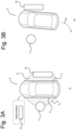
- Figure 3A-3B show top views of a vehicle in a second driving cycle of park out between times t 5 (in 3A) and t 6 (in 3B), following a drive-off time t d , the driving cycle using the stored map from the prior first driving cycle t c -t s of Fig. 2A-2D .
- the second driving cycle shows the same parking space P as in Fig. 2A-2D .
- the vehicle has been powered up from the sleep mode in which it had entered at the end of the first driving cycle at t s .
- the obstacle 10 as a stationary obstacle, e.g. a wall, is at the same position in the vicinity of the vehicle.
- a new obstacle 11 has been placed next to the vehicle.
- the retrieved map may be used for visual aid to a driver via a display in the vehicle.
- the retrieved map may as well be used to provide an audio warning and/or audio driving assistance to the driver through an audio system in the vehicle, e.g. speakers.
- the retrieved map may as well serve to assist a driving of the vehicles so as to avoid the obstacle while park out.
- Sensors 2, 3 that have been re-activated out of the sleep mode may further measure from t 5 real time data/point cloud of obstacle 10 and the new obstacle 11.
- the new obstacle 11 is in the field of view F 2 of sensors 2.
- the new measurements that are done from the moment t 5 serve to update the retrieved map in real time and avoid contact with obstacle 11.
- the retrieved map that was generated during the previous driving cycle of Figs. 2A-2C ensures a safe drive off to the vehicle in a direction Dr back to the road.
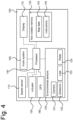
- FIG. 4 shows a diagram of an electronic control unit 100.
- the electronic control unit 100 can be implemented at least partially or entirely within or onto a vehicle, such as the vehicle of Fig.2A-2D .
- the electronic control unit 100 comprises a processor 140 that is in electronic connection with other elements of the electronic control unit 100.
- the processor 140 can instruct other elements of the control unit 100 using a given set of instructions 135 saved in a non-volatile memory 130 to which the processor is connected.
- the non-volatile memory 130 serves to store map data 133. Map data corresponding to a three-dimensional map is created from environmental data measured by one or more of environmental sensors 120, such as detailed above in the description of Fig. 2A-2D .
- Environmental sensors of the electronic control unit 100 include a camera 121, an ultrasonic sensor 122, a LiDAR sensor 123, and a radar sensor 124.
- the electronic control unit further comprises one or more actuators 150 or other driving assistance in the vehicle, so as to allow automatic braking and/or steering based on the environmental map.
- the electronic control unit comprises an audio system 160 that can generate an audio warning and/or audio driving assistance based on instructions from the processor.
- the electronic control unit further comprises a display 170 that serves as a visual aid to a vehicle driver or passenger based on the three-dimensional map.
- the electronic control unit comprise a GPS 180 to measure the position of the vehicle and compare it positions of known parking areas.
- Figure 5 shows a flowchart of a control routine 200 for safe park out of a vehicle such as vehicle 1 leaving parking space P in Fig. 3B .
- the speed sensor 110 checks whether a speed of the vehicle is below 20 km/h.
- the GPS 180 measures whether a position of the vehicle to correspond with a known parking area of the GPS. If only step 210 is performed, and the speed is above 20 km/h, the routine is not executed as the vehicle is considered not about to park, and the speed sensor continues to measure vehicle speeds. If only step 220 is performed and the vehicle measured not to be in a known parking area, the method is not performed as the vehicle is considered not about to park.
- step 230 If both steps 210 and 220 are performed and none of the speed or the vehicle position are within a given range, nothing happens and step 230 is not carried out. If the vehicle speed is below 20 km/h and/or a GPS position is within a known parking area, the environmental sensors 120 will in step 230 start collecting sensor data of the environment surrounding the vehicle in motion. The measured data is used to create and continuously update an environmental map of objects and free space. In step 240 the vehicle may be parked and stationary. If not, the sensors continue with step 230. At least one of steps 210 and 220 may be performed in order to check whether the vehicle is still about to park. If not, step 230 is not performed.
- the created environmental map is stored in the non-volatile memory 130 at step 250.
- map data of all mobile objects and of remote stationary objects outside a circle of relevance around the vehicle with a radius of for instance 10 m may be discarded in order to save memory space.
- the electronic control unit 100 is entered in the sleep mode.
- the driver preparing to leave the parking spot, and/or automatic start of the driving assistance reactivates the electronic control unit.
- map data previously saved in the non-volatile memory 130 is retrieved.
- existing retrieved map data is complemented by real-time data measured from the park out time.
- the map and/or updated map is used to provide driver assistance or automatic driving assistance.
Landscapes
- Engineering & Computer Science (AREA)
- Remote Sensing (AREA)
- Radar, Positioning & Navigation (AREA)
- Physics & Mathematics (AREA)
- Mechanical Engineering (AREA)
- Automation & Control Theory (AREA)
- Transportation (AREA)
- Computer Networks & Wireless Communication (AREA)
- General Physics & Mathematics (AREA)
- Electromagnetism (AREA)
- Acoustics & Sound (AREA)
- Human Computer Interaction (AREA)
- Chemical & Material Sciences (AREA)
- Combustion & Propulsion (AREA)
- Traffic Control Systems (AREA)
Abstract
Description
- The disclosure describes an electronic control unit for a vehicle. The disclosure further describes a method for safe park out of a vehicle using the electronic control unit.
- It is known to initiate a forward parking operation of a vehicle after a previous measurement of the parking space. The vehicle that is to be parked is driven past a parking space and measures the parking space using suitable environmental sensors. Starting from a starting position, a driver assist unit calculates a parking trajectory and moves the vehicle to a position that is best suitable for a forward parking operation.
- Once in the parking space, the vehicle may collide with objects around it upon leaving of the parking space in the next driving cycle. These objects may not be accurately detected as many environmental sensors have a reduced accuracy when the ego vehicle is standing still or the speed is very low, due to limitations in triangulation reference points. This results in problems in determining position, size and distance to an object.
- Furthermore, when in the parking space, the surrounding objects can often be very close to the vehicle. Many types of sensors are not designed to detect objects in close proximity to the vehicle and may overlook such objects completely. Also, the travelling distance between the ego vehicle and an object forming a potential threat may be very short so that limited time is available for collecting sufficient sensor data at vehicle start up when the vehicle is moving. Furthermore, detection of objects around the parking space may be hindered by weather and lighting conditions having changed and being less favorable when parking off compared to when the vehicle was parked in.
- It is an object of the disclosure to provide an electronic control unit for a vehicle and a respective method that allows the vehicle to leave a parking spot in a more reliable and safe manner.
- According to a first aspect of the disclosure, an electronic control unit for a vehicle, comprises:
at least one object sensor for sensing objects in an environment in a vicinity of the vehicle, a position sensor for sensing a speed of the vehicle and/or for sensing a position of the vehicle, a non-volatile memory, a processor connected to the object sensor, the position sensor, and the non-volatile memory, the processor being configured to instruct the object sensor to sense and collect data on the environment in the vicinity of the vehicle from a collect time tc when the position sensor measures a vehicle speed below a predetermined threshold and/or measures a vehicle position that corresponds to a position of a parking area, the processor creating an environmental map of stationary objects around the vehicle on the basis of data of the at least one object sensor and storing the environmental map in the non-volatile memory prior to a sleep time ts, following on the collect time tc, when the electronic control unit is placed in a sleep mode. - The disclosure provides an electronic control unit and one or more sensors for mounting on and within a vehicle, that obtains more reliable parking environment data during the parking in process and that uses the data during a later driving cycle at a next startup of the vehicle, when parking off. By collecting data when there is still a relative speed between the vehicle and the objects in the parking area, more reliable data can be collected and the likelihood that an object around the vehicle is detected correctly is increased. Furthermore, the sensor data can at the relatively low speed be collected from different angles, essentially eliminating blind spots and increasing confidence. Reusable sensor data can be collected from different distances as the vehicle approaches the parking spot, which means the optimal detection ranges for different sensor types can all be satisfied. By combining the sensor data into an environmental map, storage, further display, and usage of data are facilitated. Stationary objects are the sole objects of relevance that are recalled from the non-volatile memory for a next driving cycle.
- The processor may be further configured to retrieve the environmental map from the non-volatile memory after a drive off time td, following on the sleep time ts, when an increase in vehicle speed is initiated and the electronic control unit is re-activated out of the sleep mode.
- The storage of an environmental map by the electronic control unit in the non-volatile memory allows for the previously measured map to help the driver or to provide driving assistance of the vehicle in a new driving cycle when driving off from the parking space. Based on higher quality of the data that was collected at parking in, a safer parking out is provided.
- The processor may further instruct the at least one object sensor to collect further data, starting at the drive-off time td, the processor complementing the stored environmental map with the further data to an updated map.
- The electronic control unit provides an improved driving assistance for parking out, by detecting new obstacles that have entered into the parking area and combining the newly measured data with the data that was collected during the first driving cycle when parking in.
- The electronic control unit may further comprise a display connected to the processor, the processor providing a visual aid for a driver of the vehicle after the drive-off time td and based on the retrieved environmental map and/or on the updated map. The display provides a visual assistance to a driver when driving out from a parking space, based on the environmental map that was created at parking in.
- The electronic control unit may further comprise an audio system connected to the processor to provide an audio warning after the drive-off time td, based on the retrieved environmental map and/or on the updated map. The electronic control unit warns the driver through an acoustic signal when the vehicle is in the vicinity of an obstacle, on the basis of the environmental map.
- The electronic control unit may further comprise an automatic braking system or an actuator to reduce a vehicle speed and/or steer the vehicle starting after the drive-off time td, based on the retrieved environmental map and/or on the updated map. The electronic control unit may activate the vehicle's driving assistance to avoid obstacles based on the environmental map data.
- The environmental map may comprise a proximity map of the vicinity of the vehicle corresponding to a circle of at most 10m radius measured from an outer edge of the vehicle, preferably 5m radius. The processing of the environmental map to a proximity map at a closer vicinity of the vehicle within o circle of reduced diameter around the vehicle, may comprise discarding part of the data to reduce storage requirements of the non-volatile memory and reducing memory. By focusing on a relevant volume around the vehicle that is scanned by the sensors, an increased point to volume (m3) ratio at a given depth is obtained.
- The object sensor may comprise at least one of an ultrasonic sensor, lidar, radar and camera. The electronic control unit allows to collect spatial data of the position of objects around vehicle by a combination of a number of different types of sensors, depending on the sensors' availability.
- The processor using a threat evaluation algorithm to identify when an automatic intervention is needed to avoid collision based on the retrieved environmental map and a vehicle trajectory.
- The electronic control unit at park out evaluates potential threats, based on the environmental map data that was obtained at park in and allows a take over from manual driving to assisted driving.
- According to a second aspect of the disclosure, a method for safe park out of a vehicle at a drive off time td, comprises: collecting data with one or more sensors placed on the outside of a vehicle, creating an environmental map of stationary objects around the vehicle based on the collected data, storing the environmental map in a non-volatile memory when the vehicle is parked.
- The method for safe park out provides storage of reliable data measured at park in and saving the data in a map form for usage in a future driving cycle during park out. The method may comprise additional data collection when at park out while there is a relative speed between the vehicle and a measured object that is larger than zero so that an object around the vehicle is detected correctly. Furthermore, sensor data can also be collected from different angles, essentially eliminating blind spots and increasing confidence. Reusable sensor data can be collected from different distances as the vehicle approaches the parking spot, which means the optimal detection ranges of different sensor types can all be satisfied. Data that is combined into a map facilitates storage, further display and usage of the data. Stationary objects are sole objects of relevance to recall from the non-volatile memory for a next driving cycle.
- The collection of the data with the one or more sensors may start at a collect time tc when the speed of the vehicle is below 20 kilometer per hour and/or the location of the vehicle is measured to correspond with a parking area.
- Efficient sensor measurement is triggered by a low speed of the vehicle and/or the vicinity of the vehicle to a parking area. The method prevents sensor measurements from occurring when the vehicle is not about to park, and avoids collecting environmental data that is not relevant for parking out.
- The stored environmental map may be retrieved from the non-volatile memory at a drive off time td, when an increase in speed of the vehicle is initiated and the electronic control unit is re-activated out of the sleep mode.
- At the time of retrieving the environmental map, new data may be collected by the one or more sensors and transmitted to the processor, the processor providing an updated support to the driver for departure, the updated support corresponding to a combination of the stored environmental map and the new data.
- The method provides for update of the retrieved map saved at park in, at park out, to allow for new obstacles to be detected. In so doing the accuracy of the driver assistance that is provided is increased.
- The disclosure will be explained in more detail below with reference to drawings in which illustrative embodiments of the disclosure are shown. It will be appreciated by the person skilled in the art that other alternative and equivalent embodiments of the disclosure can be conceived and reduced to practice without departing from the true spirit of the disclosure, the scope of the disclosure being limited only by the appended claims.
-
Figures 1A-1B show top views of a parked vehicle powered to park out and subsequently colliding, illustrating a problem of the prior art, -
Figures 2A-2D show top views of a vehicle in motion and parking in during a first driving cycle of parking between collect time tc, before entering a sleep-mode at sleep time ts, -
Figures 3A-3B show top views of a vehicle during a second driving cycle of parking, corresponding to park out, following a drive-off time td, using data from the prior driving cycle offigures 2A-2D , -
Figure 4 shows a schematic of an electronic control unit for a vehicle, -
Figure 5 shows a flowchart of a method for safe parking out. -
Figures 1A-1B show top views of a parkedvehicle 1 powered at time t0 to park out (1A) and undesirably colliding with anobstacle 10 at time t1 ≳ t0 (in 1B), illustrating a problem of the prior art.Figure 1A shows thevehicle 1 parked in a parking space P. The vehicle has just been powered and the driver or the assisted driving prepares to leave the parking space P in a parking out direction Dr for the road. The parking spot P comprises at least oneobstacle 10 at one side, relatively close to thevehicle 1. The obstacle may be low and is hence not visible from the driver position. Thevehicle 1 comprises one ormore sensors obstacle 10 with one or more of the sensors,e.g. sensors 3 due to their location at the vehicle and intrinsic field of view, a combination of which is shown as a field of view F3 overlapping with theobstacle 10. In some cases, theobstacle 10 may not be detected if it is located in a sensor blind spot. InFig. 1B theobstacle 10 has been sensed from limited viewpoints, resulting in a high risk of collision between thevehicle 1 and theobstacle 10, especially at higher speeds of the vehicle A collision between the vehicle and the obstacle may occur in point C. -
Figure 2A-2D shows top views of avehicle 1 in motion at successive times tc, tc2 and tc3 and in a stationary parked position at ts in an exemplary first driving cycle. The situation of the first driving cycle as illustrated shows an example of parking area P with anobstacle 10. InFig. 2A , thevehicle 1 in motion approaches a parking space P at a time tc. Thevehicle 1 is shown to be a car but is not limited thereto and may be any of a bus, motorbike, truck or any other engine-powered road vehicle. Thevehicle 1 moves at time tc on a low-speed road or within a parking lot. The fact that the vehicle is approaching a parking space is detected by a vehicle speed dropping below a threshold of 20 km/h and/or a GPS position corresponding to a known parking area. The threshold may also be of 15 km/h, more preferably of 10 km/h. A known parking area may correspond with any of urban city areas, garages, dedicated parking areas registered in GPS maps. The speed threshold and GPS position may be evaluated within the vehicle by respective speed sensor and/or GPS. - The vehicle comprises one or more
environmental sensors 2, 3 (not shown) inside thevehicle 1 and/or on an external surface of thevehicle 1. Theenvironmental sensors environmental sensors obstacle 10. The obstacle may be for instance a concrete barrier, a stone or a wall. The obstacle could damage the vehicle if the vehicle came into contact with it. Eachobstacle 10 in the field of view FL1 of theenvironmental sensors 2 is detected as a multitude of three-dimensional space coordinates in the field of view of the sensor, e.g as a point cloud. Such a point cloud can be created either per sensor type or by combining the detector signals of all sensors. An environmental map of objects and free space is extracted from the point cloud by analyzing local variations in the intensity of detection samples in the point cloud. High intensity, i.e. many detections in a specific area, indicates a high probability that an object is occupying that area. Low intensity, i.e. few detections in a specific area, indicates a high probability of free space. In this environmental map, objects represent obstacles that could cause collision, and free space represents a drivable area where the vehicle can safely travel. This environmental map may be used in a next driving cycle starting after the parking time ts by an intelligent algorithm that can identify potential threats and send commands to any steering/braking actuator, sound system, or other driving assistance of the vehicle. The vehicle in motion inFig. 2A further reaches a number of different other orientations. -
Figures 2B, 2C shows two orientations of thevehicle 1 during parking at times tc2 > tc and tc3 > tc2, in each of which the vehicle still senses thesame obstacle 10 from a different field of view, FL2 and FL3, respectively. The different fields of view arise from different positions of the vehicle relative to theobstacle 10 during parking in. Each environmental sensor observes theobstacle 10 from these different orientations. A point of the obstacle surface may be scanned multiple sensors at different times. The measurements of a point on the object at different times from different angles by one or more sensors results in a high quality of the measured data. New map data measured at subsequent times, tc2 and tc3, may serve to continuously update the environmental map created from the measurement at previous time tc. A storage of the environmental map of the parking area P must occur before the vehicle is parked and powered off at time ts shown inFig 2D . This map is saved to a non-volatile memory so that the data remains available for a next driving cycle. Part of the map data may be discarded before saving, for instance data relating to mobile objects that are of minor to no interest for a future driving cycle. For instance, map data relating to distances exceeding 10 m radius around an outer edge of the vehicle, preferably 5m radius around the outer edge of the vehicle may be discarded in order to save space in the non-volatile memory. The discarding of data may occur at any time until ts, preferably at ts. -
Figure 2D shows that at ts thevehicle 1 has been parked successfully at the desired parking space P. The vehicle is locked and the sensors and other electronic elements enter a sleep mode. -
Figure 3A-3B show top views of a vehicle in a second driving cycle of park out between times t5 (in 3A) and t6 (in 3B), following a drive-off time td, the driving cycle using the stored map from the prior first driving cycle tc-ts ofFig. 2A-2D . The second driving cycle shows the same parking space P as inFig. 2A-2D . - As shown in
Fig. 3A at time t5, the vehicle has been powered up from the sleep mode in which it had entered at the end of the first driving cycle at ts. Theobstacle 10, as a stationary obstacle, e.g. a wall, is at the same position in the vicinity of the vehicle. Anew obstacle 11 has been placed next to the vehicle. An electronic control unit within the vehicle, of which the environmental sensors are part, and controlled by a processor, retrieves at time t5 the environmental map from the non-volatile memory. The retrieved map may be used for visual aid to a driver via a display in the vehicle. The retrieved map may as well be used to provide an audio warning and/or audio driving assistance to the driver through an audio system in the vehicle, e.g. speakers. The retrieved map may as well serve to assist a driving of the vehicles so as to avoid the obstacle while park out.Sensors obstacle 10 and thenew obstacle 11. Thenew obstacle 11 is in the field of view F2 ofsensors 2. The new measurements that are done from the moment t5, serve to update the retrieved map in real time and avoid contact withobstacle 11. Infigure 3B , at a time t6, the retrieved map that was generated during the previous driving cycle ofFigs. 2A-2C , ensures a safe drive off to the vehicle in a direction Dr back to the road. -
Figure 4 shows a diagram of anelectronic control unit 100. Theelectronic control unit 100 can be implemented at least partially or entirely within or onto a vehicle, such as the vehicle ofFig.2A-2D . Theelectronic control unit 100 comprises aprocessor 140 that is in electronic connection with other elements of theelectronic control unit 100. Theprocessor 140 can instruct other elements of thecontrol unit 100 using a given set ofinstructions 135 saved in anon-volatile memory 130 to which the processor is connected. Thenon-volatile memory 130 serves to storemap data 133. Map data corresponding to a three-dimensional map is created from environmental data measured by one or more ofenvironmental sensors 120, such as detailed above in the description ofFig. 2A-2D . Environmental sensors of theelectronic control unit 100 include acamera 121, anultrasonic sensor 122, aLiDAR sensor 123, and a radar sensor 124.The electronic control unit further comprises one ormore actuators 150 or other driving assistance in the vehicle, so as to allow automatic braking and/or steering based on the environmental map. The electronic control unit comprises anaudio system 160 that can generate an audio warning and/or audio driving assistance based on instructions from the processor. The electronic control unit further comprises adisplay 170 that serves as a visual aid to a vehicle driver or passenger based on the three-dimensional map. The electronic control unit comprise aGPS 180 to measure the position of the vehicle and compare it positions of known parking areas. -
Figure 5 shows a flowchart of acontrol routine 200 for safe park out of a vehicle such asvehicle 1 leaving parking space P inFig. 3B . Atstep 210 thespeed sensor 110 checks whether a speed of the vehicle is below 20 km/h. Atstep 220 theGPS 180 measures whether a position of the vehicle to correspond with a known parking area of the GPS. Ifonly step 210 is performed, and the speed is above 20 km/h, the routine is not executed as the vehicle is considered not about to park, and the speed sensor continues to measure vehicle speeds. Ifonly step 220 is performed and the vehicle measured not to be in a known parking area, the method is not performed as the vehicle is considered not about to park. If bothsteps environmental sensors 120 will instep 230 start collecting sensor data of the environment surrounding the vehicle in motion. The measured data is used to create and continuously update an environmental map of objects and free space. Instep 240 the vehicle may be parked and stationary. If not, the sensors continue withstep 230. At least one ofsteps step 240, the created environmental map is stored in thenon-volatile memory 130 atstep 250. In this step, map data of all mobile objects and of remote stationary objects outside a circle of relevance around the vehicle with a radius of for instance 10 m, may be discarded in order to save memory space. Atstep 260 theelectronic control unit 100 is entered in the sleep mode. Atstep 270, the driver preparing to leave the parking spot, and/or automatic start of the driving assistance, reactivates the electronic control unit. At this moment map data previously saved in thenon-volatile memory 130 is retrieved. Atstep 280 existing retrieved map data is complemented by real-time data measured from the park out time. Atstep 290 the map and/or updated map is used to provide driver assistance or automatic driving assistance.
Claims (15)
- An electronic control unit (100) for a vehicle (1), comprising:at least one object sensor (120) for sensing objects in an environment in a vicinity of the vehicle,a position sensor (110, 180) for sensing a speed of the vehicle and/or for sensing a position of the vehicle,a non-volatile memory (130),a processor (140) connected to the object sensor (120), the position sensor (110, 180), and the non-volatile memory (130),the processor (140) being configured to instruct the object sensor (120) to sense and collect data on the environment in the vicinity of the vehicle (1) from a collect time tc when the position sensor (110, 180) measures a vehicle speed below a predetermined threshold and/or measures a vehicle position that corresponds to the position of a parking area,the processor (140) creating an environmental map of stationary objects around the vehicle on the basis of data of the at least one object sensor (120) and storing the environmental map in the non-volatile memory (130) prior to a sleep time ts, following on the collect time tc, when the electronic control unit is placed in a sleep mode.
- The electronic control unit (100) of claim 1, the processor (140) further configured to retrieve the environmental map from the non-volatile memory (130) after a drive-off time td, following on the sleep time ts, when an increase in vehicle speed is initiated and the electronic control unit (100) is re-activated out of the sleep mode.
- The electronic control unit (100) of claim 2, the processor (140) further instructing the at least one object sensor (120) to collect further data, starting at the drive-off time ts, the processor complementing the stored environmental map with the further data to an updated map.
- The electronic control unit (100) according to any of claim 2 or 3, further comprising a display (170) connected to the processor (140), the processor (140) providing a visual aid for a driver of the vehicle (1) after the drive-off time td and based on the retrieved environmental map and/or on the updated map.
- The electronic control unit (100) according to any of claims 2 to 4, further comprising an audio system (160) connected to the processor (140) to provide an audio warning after the drive-off time td, based on the retrieved environmental map and/or on the updated map.
- The electronic control unit (100) according to any of claims 2 to 5, the electronic control unit further comprising an automatic braking system or an actuator (150) to reduce a vehicle speed and/or steer the vehicle starting after the drive-off time td, based on the retrieved environmental map and/or on the updated map.
- The electronic control unit (100) according to any of the preceding claims, the environmental map comprising a proximity map of the vicinity of the vehicle corresponding to a circle of at most 10m radius measured from an outer edge of the vehicle, preferably 5m radius.
- The electronic control unit (100) according to any of the preceding claims, the object sensor (120) comprising at least one of an ultrasonic sensor, lidar, radar and camera.
- An electronic control unit (100) for a vehicle according to any of claims 3-8 when dependent on claim 2, the processor (140) using a threat evaluation algorithm to identify when an automatic intervention is needed to avoid collision based on the retrieved environmental map and a vehicle trajectory.
- Method (200) for safe park off of a vehicle at a drive-off time td, comprising:collecting data with one or more sensors (230) placed on the outside of a vehicle,creating an environmental map of stationary objects around the vehicle based on the collected data,storing the environmental map (250) in a non-volatile memory when the vehicle is parked.
- Method (200) according to claim 10, collecting the data with the one or more sensors (230) starting at a collect time tc when the speed of the vehicle is below 20 kilometer per hour and/or the location of the vehicle is measured to correspond with a parking area.
- Method (200) according to claim 10 or 11, the stored environmental map being retrieved from the non-volatile memory at a drive-off time td, when an increase in speed of the vehicle is initiated and the electronic control unit (100) is re-activated out of the sleep mode.
- Method (200) according to claim 12, at the time of retrieving the environmental map (250), new data (280) being collected by the one or more sensors and transmitted to the processor, the processor providing an updated support to the driver for departure (290), the updated support corresponding to a combination of the stored environmental map (250) and the new data.
- An electronic control unit (100), comprising means (140) for carrying out the method of any of claims 1-13.
- A computer program comprising instructions which, when the program is executed by a computer, cause the computer to carry out the steps of any of claims 1-13.
Priority Applications (4)
| Application Number | Priority Date | Filing Date | Title |
|---|---|---|---|
| EP21213104.9A EP4194320A1 (en) | 2021-12-08 | 2021-12-08 | Electronic control unit for park out of a vehicle |
| US18/059,602 US20230182735A1 (en) | 2021-12-08 | 2022-11-29 | Method and control system for limiting a driver acceleration request |
| CN202211553859.6A CN116279452A (en) | 2021-12-08 | 2022-12-06 | Electronic control unit for vehicle, and vehicle safe parking method and program using the same |
| US18/985,804 US20250171023A1 (en) | 2021-12-08 | 2024-12-18 | Electronic control unit for park out of a vehicle |
Applications Claiming Priority (1)
| Application Number | Priority Date | Filing Date | Title |
|---|---|---|---|
| EP21213104.9A EP4194320A1 (en) | 2021-12-08 | 2021-12-08 | Electronic control unit for park out of a vehicle |
Publications (1)
| Publication Number | Publication Date |
|---|---|
| EP4194320A1 true EP4194320A1 (en) | 2023-06-14 |
Family
ID=78824665
Family Applications (1)
| Application Number | Title | Priority Date | Filing Date |
|---|---|---|---|
| EP21213104.9A Pending EP4194320A1 (en) | 2021-12-08 | 2021-12-08 | Electronic control unit for park out of a vehicle |
Country Status (3)
| Country | Link |
|---|---|
| US (2) | US20230182735A1 (en) |
| EP (1) | EP4194320A1 (en) |
| CN (1) | CN116279452A (en) |
Families Citing this family (2)
| Publication number | Priority date | Publication date | Assignee | Title |
|---|---|---|---|---|
| KR20240095700A (en) * | 2022-12-16 | 2024-06-26 | 현대자동차주식회사 | Apparatus and method for controlling an autonomous driving vehicle |
| EP4739554A1 (en) * | 2023-07-05 | 2026-05-13 | Karma Automotive, Inc. | Adaptive eco cruise strategy for improved electric vehicle effciency and range |
Citations (5)
| Publication number | Priority date | Publication date | Assignee | Title |
|---|---|---|---|---|
| DE102013015349A1 (en) * | 2013-09-17 | 2014-04-10 | Daimler Ag | Method for starting-up of vehicle for parking in parking lot, involves determining whether vehicle is to be parked in home parking lot or home parking zone when starting-up vehicle, based on identified environmental data of vehicle |
| CN110126817A (en) * | 2018-12-16 | 2019-08-16 | 初速度(苏州)科技有限公司 | A kind of method and system parked or recalled between adaptive arbitrary point and fixed point |
| DE102019209049B3 (en) * | 2019-06-21 | 2020-09-03 | Volkswagen Aktiengesellschaft | Method and device for providing assistance when a motor vehicle is parked out of a perpendicular parking space |
| WO2021044616A1 (en) * | 2019-09-06 | 2021-03-11 | 日産自動車株式会社 | Parking assistance method and parking assistance device |
| US20210114585A1 (en) * | 2019-10-17 | 2021-04-22 | Toyota Jidosha Kabushiki Kaisha | Automated valet parking system |
Family Cites Families (3)
| Publication number | Priority date | Publication date | Assignee | Title |
|---|---|---|---|---|
| US11195057B2 (en) * | 2014-03-18 | 2021-12-07 | Z Advanced Computing, Inc. | System and method for extremely efficient image and pattern recognition and artificial intelligence platform |
| CN105404844B (en) * | 2014-09-12 | 2019-05-31 | 广州汽车集团股份有限公司 | A kind of Method for Road Boundary Detection based on multi-line laser radar |
| US12326919B2 (en) * | 2017-12-05 | 2025-06-10 | Aurora Operations, Inc. | Multiple stage image based object detection and recognition |
-
2021
- 2021-12-08 EP EP21213104.9A patent/EP4194320A1/en active Pending
-
2022
- 2022-11-29 US US18/059,602 patent/US20230182735A1/en not_active Abandoned
- 2022-12-06 CN CN202211553859.6A patent/CN116279452A/en active Pending
-
2024
- 2024-12-18 US US18/985,804 patent/US20250171023A1/en active Pending
Patent Citations (5)
| Publication number | Priority date | Publication date | Assignee | Title |
|---|---|---|---|---|
| DE102013015349A1 (en) * | 2013-09-17 | 2014-04-10 | Daimler Ag | Method for starting-up of vehicle for parking in parking lot, involves determining whether vehicle is to be parked in home parking lot or home parking zone when starting-up vehicle, based on identified environmental data of vehicle |
| CN110126817A (en) * | 2018-12-16 | 2019-08-16 | 初速度(苏州)科技有限公司 | A kind of method and system parked or recalled between adaptive arbitrary point and fixed point |
| DE102019209049B3 (en) * | 2019-06-21 | 2020-09-03 | Volkswagen Aktiengesellschaft | Method and device for providing assistance when a motor vehicle is parked out of a perpendicular parking space |
| WO2021044616A1 (en) * | 2019-09-06 | 2021-03-11 | 日産自動車株式会社 | Parking assistance method and parking assistance device |
| US20210114585A1 (en) * | 2019-10-17 | 2021-04-22 | Toyota Jidosha Kabushiki Kaisha | Automated valet parking system |
Also Published As
| Publication number | Publication date |
|---|---|
| CN116279452A (en) | 2023-06-23 |
| US20250171023A1 (en) | 2025-05-29 |
| US20230182735A1 (en) | 2023-06-15 |
Similar Documents
| Publication | Publication Date | Title |
|---|---|---|
| US20250171023A1 (en) | Electronic control unit for park out of a vehicle | |
| CN110962843B (en) | A kind of automatic parking control decision-making method and system | |
| US9688272B2 (en) | Surroundings monitoring apparatus and drive assistance apparatus | |
| CN111063202B (en) | Intelligent parking management method based on electronic map | |
| KR101915167B1 (en) | Automatically parking system and automatically parking method | |
| CN110053617B (en) | Vehicle control device, vehicle control method, and storage medium | |
| CN106379319B (en) | Automobile auxiliary driving system and control method | |
| JP6115576B2 (en) | Vehicle travel control device | |
| US9720085B2 (en) | Driver assistance method for detecting objects on the side | |
| US10421394B2 (en) | Driving assistance device, and storage medium | |
| JP2020166633A (en) | Management equipment, management methods, and programs | |
| CN105988467A (en) | Autonomous driving device | |
| CN113650607B (en) | Low-speed scene automatic driving method, system and automobile | |
| WO2016181618A1 (en) | Monitored area setting device and monitored area setting method | |
| EP4046883B1 (en) | Automated valet parking system, control method of automated valet parking system, and autonomous driving vehicle | |
| WO2020166338A1 (en) | Driving assistance device | |
| WO2021238748A1 (en) | Engineering vehicle autonomous parking system and autonomous parking method suitable for construction area | |
| JP2020166460A (en) | Vehicle control device, vehicle management device, vehicle control method, vehicle management method, and program | |
| KR101779963B1 (en) | Method of enhancing performance for road-environment recognition device based on learning and apparatus for the same | |
| US20240240963A1 (en) | Parking assistance device and parking assistance method | |
| JP2017162248A (en) | Self-driving vehicle | |
| US12065142B2 (en) | Vehicle traveling control apparatus | |
| JP2014100957A (en) | Parking support device and control device | |
| US20240326788A1 (en) | Driver assistance apparatus | |
| CN115071755A (en) | Mobile object control system, mobile object control method, and storage medium |
Legal Events
| Date | Code | Title | Description |
|---|---|---|---|
| PUAI | Public reference made under article 153(3) epc to a published international application that has entered the european phase |
Free format text: ORIGINAL CODE: 0009012 |
|
| STAA | Information on the status of an ep patent application or granted ep patent |
Free format text: STATUS: THE APPLICATION HAS BEEN PUBLISHED |
|
| AK | Designated contracting states |
Kind code of ref document: A1 Designated state(s): AL AT BE BG CH CY CZ DE DK EE ES FI FR GB GR HR HU IE IS IT LI LT LU LV MC MK MT NL NO PL PT RO RS SE SI SK SM TR |
|
| STAA | Information on the status of an ep patent application or granted ep patent |
Free format text: STATUS: REQUEST FOR EXAMINATION WAS MADE |
|
| 17P | Request for examination filed |
Effective date: 20231214 |
|
| RBV | Designated contracting states (corrected) |
Designated state(s): AL AT BE BG CH CY CZ DE DK EE ES FI FR GB GR HR HU IE IS IT LI LT LU LV MC MK MT NL NO PL PT RO RS SE SI SK SM TR |
|
| STAA | Information on the status of an ep patent application or granted ep patent |
Free format text: STATUS: EXAMINATION IS IN PROGRESS |
|
| 17Q | First examination report despatched |
Effective date: 20240131 |