EP4194318A1 - Independent steering mechanism, steering system and control method - Google Patents
Independent steering mechanism, steering system and control method Download PDFInfo
- Publication number
- EP4194318A1 EP4194318A1 EP21859833.2A EP21859833A EP4194318A1 EP 4194318 A1 EP4194318 A1 EP 4194318A1 EP 21859833 A EP21859833 A EP 21859833A EP 4194318 A1 EP4194318 A1 EP 4194318A1
- Authority
- EP
- European Patent Office
- Prior art keywords
- connecting rod
- power
- assisted motor
- steering
- control
- Prior art date
- Legal status (The legal status is an assumption and is not a legal conclusion. Google has not performed a legal analysis and makes no representation as to the accuracy of the status listed.)
- Granted
Links
Images







Classifications
-
- B—PERFORMING OPERATIONS; TRANSPORTING
- B62—LAND VEHICLES FOR TRAVELLING OTHERWISE THAN ON RAILS
- B62D—MOTOR VEHICLES; TRAILERS
- B62D7/00—Steering linkage; Stub axles or their mountings
- B62D7/06—Steering linkage; Stub axles or their mountings for individually-pivoted wheels, e.g. on king-pins
- B62D7/14—Steering linkage; Stub axles or their mountings for individually-pivoted wheels, e.g. on king-pins the pivotal axes being situated in more than one plane transverse to the longitudinal centre line of the vehicle, e.g. all-wheel steering
- B62D7/15—Steering linkage; Stub axles or their mountings for individually-pivoted wheels, e.g. on king-pins the pivotal axes being situated in more than one plane transverse to the longitudinal centre line of the vehicle, e.g. all-wheel steering characterised by means varying the ratio between the steering angles of the steered wheels
- B62D7/1509—Steering linkage; Stub axles or their mountings for individually-pivoted wheels, e.g. on king-pins the pivotal axes being situated in more than one plane transverse to the longitudinal centre line of the vehicle, e.g. all-wheel steering characterised by means varying the ratio between the steering angles of the steered wheels with different steering modes, e.g. crab-steering, or steering specially adapted for reversing of the vehicle
-
- B—PERFORMING OPERATIONS; TRANSPORTING
- B62—LAND VEHICLES FOR TRAVELLING OTHERWISE THAN ON RAILS
- B62D—MOTOR VEHICLES; TRAILERS
- B62D5/00—Power-assisted or power-driven steering
- B62D5/04—Power-assisted or power-driven steering electrical, e.g. using an electric servo-motor connected to, or forming part of, the steering gear
- B62D5/0457—Power-assisted or power-driven steering electrical, e.g. using an electric servo-motor connected to, or forming part of, the steering gear characterised by control features of the drive means as such
-
- B—PERFORMING OPERATIONS; TRANSPORTING
- B62—LAND VEHICLES FOR TRAVELLING OTHERWISE THAN ON RAILS
- B62D—MOTOR VEHICLES; TRAILERS
- B62D5/00—Power-assisted or power-driven steering
- B62D5/04—Power-assisted or power-driven steering electrical, e.g. using an electric servo-motor connected to, or forming part of, the steering gear
- B62D5/0457—Power-assisted or power-driven steering electrical, e.g. using an electric servo-motor connected to, or forming part of, the steering gear characterised by control features of the drive means as such
- B62D5/0481—Power-assisted or power-driven steering electrical, e.g. using an electric servo-motor connected to, or forming part of, the steering gear characterised by control features of the drive means as such monitoring the steering system, e.g. failures
- B62D5/0487—Power-assisted or power-driven steering electrical, e.g. using an electric servo-motor connected to, or forming part of, the steering gear characterised by control features of the drive means as such monitoring the steering system, e.g. failures detecting motor faults
-
- B—PERFORMING OPERATIONS; TRANSPORTING
- B62—LAND VEHICLES FOR TRAVELLING OTHERWISE THAN ON RAILS
- B62D—MOTOR VEHICLES; TRAILERS
- B62D7/00—Steering linkage; Stub axles or their mountings
- B62D7/20—Links, e.g. track rods
-
- B—PERFORMING OPERATIONS; TRANSPORTING
- B62—LAND VEHICLES FOR TRAVELLING OTHERWISE THAN ON RAILS
- B62D—MOTOR VEHICLES; TRAILERS
- B62D5/00—Power-assisted or power-driven steering
- B62D5/04—Power-assisted or power-driven steering electrical, e.g. using an electric servo-motor connected to, or forming part of, the steering gear
-
- B—PERFORMING OPERATIONS; TRANSPORTING
- B62—LAND VEHICLES FOR TRAVELLING OTHERWISE THAN ON RAILS
- B62D—MOTOR VEHICLES; TRAILERS
- B62D5/00—Power-assisted or power-driven steering
- B62D5/04—Power-assisted or power-driven steering electrical, e.g. using an electric servo-motor connected to, or forming part of, the steering gear
- B62D5/0457—Power-assisted or power-driven steering electrical, e.g. using an electric servo-motor connected to, or forming part of, the steering gear characterised by control features of the drive means as such
- B62D5/0481—Power-assisted or power-driven steering electrical, e.g. using an electric servo-motor connected to, or forming part of, the steering gear characterised by control features of the drive means as such monitoring the steering system, e.g. failures
- B62D5/0484—Power-assisted or power-driven steering electrical, e.g. using an electric servo-motor connected to, or forming part of, the steering gear characterised by control features of the drive means as such monitoring the steering system, e.g. failures for reaction to failures, e.g. limp home
-
- B—PERFORMING OPERATIONS; TRANSPORTING
- B62—LAND VEHICLES FOR TRAVELLING OTHERWISE THAN ON RAILS
- B62D—MOTOR VEHICLES; TRAILERS
- B62D6/00—Arrangements for automatically controlling steering depending on driving conditions sensed and responded to, e.g. control circuits
- B62D6/002—Arrangements for automatically controlling steering depending on driving conditions sensed and responded to, e.g. control circuits computing target steering angles for front or rear wheels
-
- B—PERFORMING OPERATIONS; TRANSPORTING
- B62—LAND VEHICLES FOR TRAVELLING OTHERWISE THAN ON RAILS
- B62D—MOTOR VEHICLES; TRAILERS
- B62D7/00—Steering linkage; Stub axles or their mountings
- B62D7/06—Steering linkage; Stub axles or their mountings for individually-pivoted wheels, e.g. on king-pins
- B62D7/08—Steering linkage; Stub axles or their mountings for individually-pivoted wheels, e.g. on king-pins the pivotal axes being situated in a single plane transverse to the longitudinal centre line of the vehicle
- B62D7/09—Steering linkage; Stub axles or their mountings for individually-pivoted wheels, e.g. on king-pins the pivotal axes being situated in a single plane transverse to the longitudinal centre line of the vehicle characterised by means varying the ratio between the steering angles of the steered wheels
Definitions
- This application relates to the vehicle field, and more specifically, to an independent steering mechanism, a steering system, and a control method in a vehicle.
- a steering mechanism is designed according to Ackermann (Ackermann) steering geometry, so that a steering angle of an inner wheel is 2 to 4 degrees greater than a steering angle of an outer wheel during steering of the vehicle, so that the vehicle can be steered smoothly.
- a steer-by-wire technology can be applied to a steering system of the vehicle.
- a conventional vehicle steering system is a mechanical system, and a vehicle steering motion is implemented by manipulating a driving wheel by a driver and transferring the manipulation to steering wheels through a steering gear and a series of rods.
- a mechanical connection between the driving wheel and the steering wheels is cancelled, and steering is implemented completely by electric energy.
- left and right steering wheels can be controlled independently, which can better meet requirements of future vehicles and implement flexible steering.
- the steer-by-wire independent technology when one of steering motors respectively configured for the left and right steering wheels is faulty, overall steering needs to be recovered, and an independent steering function is lost.
- Embodiments of this application provide an independent steering mechanism, a steering system, and a control method.
- a plurality of power-assisted motors are disposed to implement an independent steering function, and resolve a problem that when one of the power-assisted motors is faulty, independent steering cannot be performed without changing a mechanical structure.
- an independent steering mechanism including: a first power-assisted motor, a second power-assisted motor, a third power-assisted motor, and a middle tie rod.
- the middle tie rod includes a first connecting rod, a second connecting rod, and a third connecting rod, and two ends of the third connecting rod are connected to the first connecting rod and the second connecting rod.
- the first power-assisted motor is configured to control the first connecting rod to move along an axial direction of the middle tie rod
- the second power-assisted motor is configured to control the second connecting rod to move along the axial direction of the middle tie rod
- the third power-assisted motor is configured to control the third connecting rod to rotate, to drive the first connecting rod and the second connecting rod to approach or move away from each other along the axial direction of the middle tie rod.
- the first power-assisted motor, the second power-assisted motor, and the third power-assisted motor may respectively control the first connecting rod, the second connecting rod, and the third connecting rod, to adjust a length and a position of the middle tie rod.
- the length and the position of the middle tie rod can still be adjusted by using two power-assisted motors that work normally, without changing a mechanical structure.
- the third connecting rod is of a hollow structure, and the two ends of the third connecting rod are connected to the first connecting rod and the second connecting rod through screw threads.
- the third connecting rod is of the hollow structure, and the two ends of the third connecting rod are connected to the first connecting rod and the second connecting rod through the screw threads. That is, the third connecting rod is of a socket structure, and one end of the first connecting rod and one end of the second connecting rod are respectively disposed in openings on two sides of the socket structure, and are connected through the screw threads.
- the first connecting rod and the second connecting rod may be of hollow structures, and the two ends of the third connecting rod are connected to the first connecting rod and the second connecting rod through ball screws or screw nuts. That is, the first connecting rod and the second connecting rod are of socket structures, and the two ends of the third connecting rod are respectively disposed in openings of one end of the first connecting rod and one end of the second connecting rod.
- the screw threads at the two ends of the third connecting rod are rotated in opposite directions.
- the third motor controls the third connecting rod to rotate, so that the first connecting rod and the second connecting rod approach or move away from each other along the axial direction of the middle tie rod.
- the independent steering mechanism further includes a first transmission part, a second transmission part, and a third transmission part.
- the first power-assisted motor controls, by using the first transmission part, the first connecting rod to move along the axial direction of the middle tie rod
- the second power-assisted motor controls, by using the second transmission part, the second connecting rod to move along the axial direction of the middle tie rod
- the third power-assisted motor controls, by using the third transmission part, the third connecting rod to rotate.
- a rotational speed of the power-assisted motor is high, and the first transmission part, the second transmission part, and the third transmission part are all of transmission structures of deceleration.
- the first transmission part, the second transmission part, and the third transmission part are of belt transmission structures, but a structure of the transmission part is not limited.
- the first transmission part, the second transmission part, and the third transmission part may also be of a rack-and-pinion transmission structure, or may be of a worm-and-gear transmission structure, or may be of a transmission structure of parallel shaft gears.
- the first transmission part includes a first gear, and the first gear is connected to the first connecting rod through a screw thread.
- the first power-assisted motor drives the first gear to rotate, to control the first connecting rod to move along the axial direction of the middle tie rod.
- a screw thread may be disposed on a surface on which the first connecting rod is in contact with the first gear, and an inner side (a surface on which the first gear is in contact with the first connecting rod) of the first gear may be of a screw nut or a ball screw structure.
- the screw nut or the ball screw structure of the first gear is combined with the screw thread structure of the first connecting rod to drive the first connecting rod to move along the axial direction of the middle tie rod.
- a tooth may be disposed on an outer side (a surface on which the first gear is in contact with a first transmission belt) of the first gear, and may be meshed with a tooth disposed on an inner side (a surface on which the first transmission belt is in contact with the first gear) of the first transmission belt, to improve power transmission efficiency.
- the second transmission part includes a second gear, and the second gear is connected to the second connecting rod through a screw thread; and the second power-assisted motor drives the second gear to rotate, to control the second connecting rod to move along the axial direction of the middle tie rod.
- a screw thread may be disposed on a surface on which the second connecting rod is in contact with the second gear, and an inner side (a surface on which the second gear is in contact with the second connecting rod) of the second gear may be of a screw nut or a ball screw structure.
- a tooth may be disposed on an outer side (a surface on which the second gear is in contact with a second transmission belt) of the second gear, and may be meshed with a tooth disposed on an inner side (a surface on which the second transmission belt is in contact with the second gear) of the second transmission belt, to improve power transmission efficiency.
- the third transmission part includes a third gear.
- a guiding boss disposed along the axial direction of the middle tie rod is disposed on a surface of the third connecting rod.
- a guiding groove corresponding to the guiding boss is disposed on the third gear.
- the third gear is connected to the third connecting rod through the guiding groove and the guiding boss.
- the third power-assisted motor drives the third gear to rotate, to control the third connecting rod to rotate.
- a guiding boss may be disposed on a surface on which the third connecting rod is in contact with the third gear, and a guiding groove corresponding to the guiding boss may be disposed on an inner side (a surface on which the third gear is in contact with the third connecting rod) of the third gear.
- the guiding boss may be disposed along the axial direction of the middle tie rod, so that efficiency of power transmission between the third gear and the third connecting rod can be improved. In addition, disposing of the guiding boss does not affect movement of the third connecting rod along the axial direction of the middle tie rod.
- a tooth may be disposed on an outer side (a surface on which a third gear 172 is in contact with a third transmission belt 171) of the third gear 172, and may be meshed with a tooth disposed on an inner side (a surface on which the third transmission belt 171 is in contact with the third gear 172) of the third transmission belt 171, to improve power transmission efficiency.
- an independent steering system including: a first steering wheel, a second steering wheel, and the independent steering mechanism according to any one of the possible implementations of the first aspect.
- the first connecting rod in the independent steering mechanism is connected to the first steering wheel
- the second connecting rod in the independent steering mechanism is connected to the second steering wheel.
- the first power-assisted motor in the independent steering mechanism is configured to control the first connecting rod to move along the axial direction of the middle tie rod in the independent steering mechanism, to enable the first steering wheel to rotate
- the second power-assisted motor in the independent steering mechanism is configured to control the second connecting rod to move along the axial direction of the middle tie rod in the independent steering mechanism, to enable the second steering wheel to rotate.
- the independent steering system further includes: a first steering knuckle, a second steering knuckle, a first steering kingpin, and a second steering kingpin.
- the first steering wheel is connected to the first steering kingpin through the first steering knuckle
- the first steering knuckle is connected to the first connecting rod
- the first power-assisted motor is configured to control the first connecting rod to move along the axial direction of the middle tie rod, to enable the first steering knuckle to drive the first steering wheel to rotate around the first steering kingpin.
- the second steering wheel is connected to the second steering kingpin through the second steering knuckle, the second steering knuckle is connected to the second connecting rod, and the second power-assisted motor is configured to control the second connecting rod to move along the axial direction of the middle tie rod, to enable the second steering knuckle to drive the second steering wheel to rotate around the second steering kingpin.
- the independent steering system further includes a first tie rod and a second tie rod.
- One end of the first tie rod is connected to the first connecting rod, and the other end of the first tie rod is connected to the first steering knuckle.
- One end of the second tie rod is connected to the second connecting rod, and the other end of the second tie rod is connected to the second steering knuckle.
- the independent steering system further includes a control unit.
- the control unit is configured to determine a target steering angle of the first steering wheel and a target steering angle of the second steering wheel.
- the control unit is configured to: control the third power-assisted motor in the independent steering mechanism to adjust a length of the middle tie rod in the independent steering mechanism; and control a normal power-assisted motor in the first power-assisted motor or the second power-assisted motor to adjust a position of the middle tie rod, so that the middle tie rod drives the first steering wheel and the second steering wheel to rotate to a corresponding target steering angle.
- control unit when the first power-assisted motor and the second power-assisted motor are normal, the control unit is specifically configured to: control the first power-assisted motor and the second power-assisted motor to adjust the length of the middle tie rod and the position of the middle tie rod, so that the middle tie rod drives the first steering wheel and the second steering wheel to rotate to the corresponding target steering angle.
- the independent steering system includes: a first electronic control unit ECU, a second ECU, and a third ECU.
- the control unit is specifically configured to: send a first control instruction to the first ECU, where the first ECU is configured to control the first power-assisted motor according to the first control instruction; send a second control instruction to the second ECU, where the second ECU is configured to control the second power-assisted motor according to the second control instruction; and send a third control instruction to the third ECU, where the third ECU is configured to control the third power-assisted motor according to the third control instruction.
- control unit is specifically configured to: determine a target position of the first connecting rod and a target position of the second connecting rod based on the target steering angle of the first steering wheel and the target steering angle of the second steering wheel; and determine a target length of the middle tie rod based on the target position of the first connecting rod and the target position of the second connecting rod.
- the control unit calculates a target rotation angle of the third connecting rod in the independent steering mechanism based on the target length; controls, based on the target rotation angle, the third power-assisted motor to adjust the length of the middle tie rod to the target length, and controls, based on the target position of the first connecting rod and the target position of the second connecting rod, the normal power-assisted motor in the first power-assisted motor or the second power-assisted motor to adjust the first connecting rod and the second connecting rod to a corresponding target position.
- control unit is specifically configured to: send the third control instruction to the third ECU, where the third control instruction is used to indicate the third ECU to control the third power-assisted motor to output torque, so that the length of the middle tie rod is the target length.
- the third ECU controls the third power-assisted motor according to the third control instruction.
- control unit is specifically configured to: send the first control instruction to the first ECU, where the first control instruction is used to indicate the first ECU to control the first power-assisted motor to output torque, so that the first connecting rod and the second connecting rod rotate to the corresponding target position, or send the second control instruction to the second ECU, where the second control instruction is used to indicate the second ECU to control the second power-assisted motor to output torque, so that the first connecting rod and the second connecting rod reach the corresponding target position.
- the independent steering system further includes: a first sensor, a second sensor, and a third sensor.
- the first sensor is configured to determine position information of the first connecting rod
- the second sensor is configured to determine position information of the second connecting rod
- the third sensor is configured to determine length information of the middle tie rod.
- control unit is specifically configured to determine the first control instruction, the second control instruction, or the third control instruction based on the position information of the first connecting rod, the position information of the second connecting rod, and the length information of the middle tie rod.
- the first sensor is a translational position sensor or an angular position sensor.
- the second sensor is a translational position sensor or an angular position sensor.
- the third sensor is an angular position sensor.
- a control method for an independent steering system includes: a control unit, a first steering wheel, a second steering wheel, and the independent steering mechanism according to any one of the possible implementations of the first aspect.
- the first steering wheel and the second steering wheel are respectively connected to the first connecting rod and the second connecting rod of the middle tie rod in the independent steering mechanism, and the method includes:
- the control unit determines a target steering angle of the first steering wheel and a target steering angle of the second steering wheel.
- the control unit controls the third power-assisted motor in the independent steering mechanism to adjust a length of the middle tie rod in the independent steering mechanism, and controls a normal power-assisted motor in the first power-assisted motor or the second power-assisted motor to adjust a position of the middle tie rod, so that the middle tie rod drives the first steering wheel and the second steering wheel to rotate to a corresponding target steering angle.
- control method further includes: When the first power-assisted motor and the second power-assisted motor are normal, the control unit controls the first power-assisted motor and the second power-assisted motor to adjust the length of the middle tie rod and the position of the middle tie rod, so that the middle tie rod drives the first steering wheel and the second steering wheel to rotate to the corresponding target steering angle.
- the independent steering system includes: a first ECU, a second ECU, and a third ECU.
- the first ECU is configured to control the first power-assisted motor
- the second ECU is configured to control the second power-assisted motor
- the third ECU is configured to control the third power-assisted motor.
- the method further includes: The control unit receives first information sent by the first ECU, where the first information is used to indicate whether the first power-assisted motor is faulty.
- the control unit receives second information sent by the second ECU, where the second information is used to indicate whether the second power-assisted motor is faulty.
- the control unit receives third information sent by the third ECU, where the third information is used to indicate whether the third power-assisted motor is faulty.
- control unit controls the third power-assisted motor in the independent steering mechanism to adjust a length of the middle tie rod in the independent steering mechanism, and controls a normal power-assisted motor in the first power-assisted motor or the second power-assisted motor to adjust a position of the middle tie rod includes: The control unit determines a target position of the first connecting rod and a target position of the second connecting rod based on the target steering angle of the first steering wheel and the target steering angle of the second steering wheel. The control unit determines a target length of the middle tie rod based on the target position of the first connecting rod and the target position of the second connecting rod.
- the control unit calculates a target rotation angle of the third connecting rod in the independent steering mechanism based on the target length.
- the control unit controls, based on the target rotation angle, the third power-assisted motor to adjust the length of the middle tie rod to the target length, and controls, based on the target position of the first connecting rod and the target position of the second connecting rod, the normal power-assisted motor in the first power-assisted motor or the second power-assisted motor to adjust the first connecting rod and the second connecting rod to a corresponding target position.
- control unit controls, based on the target rotation angle, the third power-assisted motor to adjust the length of the middle tie rod to the target length includes: The control unit sends a third control instruction to the third ECU, where the third control instruction is used to indicate the third ECU to control the third power-assisted motor to output torque, so that the length of the middle tie rod is the target length; and the third ECU controls the third power-assisted motor according to the third control instruction.
- control unit sends a second control instruction to the second ECU, where the second control instruction is used to indicate the second ECU to control the second power-assisted motor to output torque, so that the first connecting rod and the second connecting rod reach the corresponding target position.
- a vehicle including the independent steering system according to any one of the possible implementations of the second aspect.
- An independent steering mechanism in the independent steering system controls steering wheels to perform steering by adjusting a length and a position of a middle tie rod.
- a control apparatus includes a processing unit and a storage unit.
- the storage unit is configured to store instructions.
- the processing unit executes the instructions stored in the storage unit, so that the control apparatus performs any possible method according to the third aspect.
- control apparatus may be an independent controller in a vehicle, or may be a chip having a control function in the vehicle.
- the processing unit may be a processor.
- the storage unit may be a memory (for example, a register or cache) in the chip, or a storage unit (for example, a read-only memory or a random access memory) that is in the vehicle and that is located outside the chip.
- the memory is coupled to the processor. That the memory is coupled to the processor may be understood as that the memory is located inside the processor, or the memory is located outside the processor, to be independent of the processor.
- a computer program product includes computer program code, and when the computer program code is run on a computer, the computer performs the method according to the foregoing aspects.
- the computer program code may be stored in a first storage medium.
- the first storage medium may be encapsulated together with a processor, or may be encapsulated separately from a processor. This is not specifically limited in embodiments of this application.
- a computer-readable medium stores program code.
- the computer program code When the computer program code is run on a computer, the computer performs the method in the foregoing aspects.
- FIG. 1 is a schematic diagram of conventional vehicle steering.
- a steering mechanism is designed according to Ackermann steering geometry.
- the steering angle of the inner wheel can be 2 to 4 degrees greater than the steering angle of the outer wheel by using equal cranks of four connecting rods, that is, a steering trapezoid shown in FIG. 1 .
- This structure allows centers of steering paths of four wheels of the vehicle to roughly intersect on an extension line of a rear axle, so that the vehicle turns smoothly.
- a conventional steering system vehicle is a mechanical system, and a vehicle steering motion is implemented by manipulating a driving wheel by a driver and by transferring the manipulation to steering wheels through a steering gear and a series of rods.
- the conventional vehicle steering system is limited by a mechanical structure of the conventional vehicle steering system, and steering is not flexible.
- a vehicle steer-by-wire system cancels a mechanical connection between the driving wheel and the steering wheels, and steering is implemented completely by electric energy.
- steering motors are respectively configured for the left and right steering wheels, so that the left and right steering wheels can rotate independently, and therefore steering of the vehicle is more flexible.
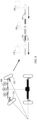
- FIG. 2 shows a steer-by-wire independent system in the conventional technology.
- a steering wheel 1 and a steering wheel 7 are respectively provided with a steering motor 2 and a steering motor 6.
- the two motors are independent of each other, and directly drive respectively corresponding steering wheels to perform steering.
- a rotating motor 4 may be used to control a left connecting piece 3 to connect to a right connecting piece 5, to change independent steering into overall steering.
- the steering motor may be used to directly drive the corresponding steering wheel to steer, and the rotating motor may be used to control separation and combination of left and right connecting pieces.
- the rotating motor 4 controls the connection of the left and right connecting pieces, normal steering is affected, and after the fault occurs, an independent steering capability is lost.
- This application provides an independent steering mechanism, an independent steering system, and a control method.
- a plurality of power-assisted motors are disposed to implement an independent steering function, and resolve a problem that when one of the power-assisted motors is faulty, independent steering cannot be performed without changing a mechanical structure.
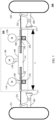
- FIG. 3 shows an independent steering mechanism according to an embodiment of this application.
- an independent steering mechanism 100 may include a first power-assisted motor 110, a second power-assisted motor 120, a third power-assisted motor 130, and a middle tie rod 140.
- the middle tie rod 140 includes a first connecting rod 142, a second connecting rod 143, and a third connecting rod 141. Two ends of the third connecting rod 141 are connected to the first connecting rod 142 and the second connecting rod 143.
- the first power-assisted motor 110 is configured to control the first connecting rod 142 to move along an axial direction of the middle tie rod 140.
- the second power-assisted motor 120 is configured to control the second connecting rod 143 to move along the axial direction of the middle tie rod 140.
- the third power-assisted motor 130 is configured to control the third connecting rod 141 to rotate to drive the first connecting rod 142 and the second connecting rod 142 to move toward or opposite to each other along the axial direction of the middle tie rod 140, and the first connecting rod 142 and the second connecting rod 142 approach or move away from each other along the axial direction of the middle tie rod 140.
- the independent steering mechanism 100 may further include a first transmission part 150, a second transmission part 160, and a third transmission part 170.
- the first power-assisted motor 110 may control, by using the first transmission part 150, the first connecting rod 142 to move along an axial direction of the middle tie rod 140.
- the second power-assisted motor 120 may control, by using the second transmission part 160, the second connecting rod 143 to move along the axial direction of the middle tie rod 140.
- the third power-assisted motor 130 may control, by using the third transmission part 170, the third connecting rod 141 to rotate.
- the third connecting rod 141 is of a hollow structure, and the two ends of the third connecting rod 141 are connected to the first connecting rod 142 and the second connecting rod 143 through screw threads. That is, the third connecting rod 141 is of a socket structure, and one end of the first connecting rod 142 and one end of the second connecting rod 143 are respectively disposed in openings on two sides of the socket structure, and are connected through the screw threads.
- first connecting rod 142 and the second connecting rod 143 may be of hollow structures, and the two ends of the third connecting rod 141 are connected to the first connecting rod 142 and the second connecting rod 143 through ball screws or screw nuts. That is, the first connecting rod 142 and the second connecting rod 143 are of socket structures, and the two ends of the third connecting rod 141 are respectively disposed in openings of one end of the first connecting rod 142 and one end of the second connecting rod 143.
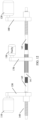
- FIG. 4 is a three-dimensional schematic diagram of an independent steering mechanism according to an embodiment of this application.
- the first transmission part 150 may include a first transmission belt 151 and a first gear 152.
- the first gear 152 has a central hole, and the first connecting rod 142 passes through the first gear 152 through the hole.
- the first transmission belt 151 may drive the first gear 152 to rotate, and further drive the first connecting rod 142 to move along the axial direction of the middle tie rod 140.
- a screw thread may be disposed on a surface on which the first connecting rod 142 is in contact with the first gear 152, and an inner side (a surface on which the first gear 152 is in contact with the first connecting rod 142) of the first gear 152 may be of a screw nut or a ball screw structure.
- the screw nut or the ball screw structure of the first gear 152 is combined with the screw thread structure of the first connecting rod 142 to drive the first connecting rod 142 to move along the axial direction of the middle tie rod 140.
- a tooth may be disposed on an outer side (a surface on which the first gear 152 is in contact with the first transmission belt 151) of the first gear 152, and may be meshed with a tooth disposed on an inner side (a surface on which the first transmission belt 151 is in contact with the first gear 152) of the first transmission belt 151, to improve power transmission efficiency.
- the second transmission part 160 may include a second transmission belt 161 and a second gear 162.
- the second gear 162 has a central hole, and the second connecting rod 143 passes through the second gear 162 through the hole.
- the second transmission belt 161 may drive the second gear 162 to rotate, and further drive the second connecting rod 143 to move along the axial direction of the middle tie rod 140.
- a screw thread may be disposed on a surface on which the second connecting rod 143 is in contact with the second gear 162, and an inner side (a surface on which the second gear 162 is in contact with the second connecting rod 143) of the second gear 162 may be of a screw nut or a ball screw structure.
- the screw nut or the ball screw structure of the second gear 162 is combined with the screw thread structure of the second connecting rod 143 to drive the second connecting rod 143 to move along the axial direction of the middle tie rod 140.
- a tooth may be disposed on an outer side (a surface on which the second gear 162 is in contact with the second transmission belt 161) of the second gear 162, and may be meshed with a tooth disposed on an inner side (a surface on which the second transmission belt 161 is in contact with the second gear 162) of the second transmission belt 161, to improve power transmission efficiency.
- the third transmission part 170 may include a third transmission belt 171 and a third gear 172.
- the third gear 172 has a central hole, and the third connecting rod 141 passes through the third gear 172 through the hole.
- the third transmission belt 171 may drive the third gear 172 to rotate, and further drive the third connecting rod 141 to rotate.
- a guiding boss 173 may be disposed on a surface on which the third connecting rod 141 is in contact with the third gear 172, and a guiding groove 174 corresponding to the guiding boss 173 may be disposed on an inner side (a surface on which the third gear 172 is in contact with the third connecting rod 141) of the third gear 172, as shown in FIG. 5 .
- the guiding boss 173 may be disposed along the axial direction of the middle tie rod 140, so that efficiency of power transmission between the third gear 172 and the third connecting rod 141 can be improved.
- disposing of the guiding boss 173 does not affect movement of the third connecting rod 141 along the axial direction of the middle tie rod 140.
- a tooth may be disposed on an outer side (a surface on which the third gear 172 is in contact with the third transmission belt 171) of the third gear 172, and may be meshed with a tooth disposed on an inner side (a surface on which the third transmission belt 171 is in contact with the third gear 172) of the third transmission belt 171, to improve power transmission efficiency.
- the first transmission part 150 and the second transmission part 160 may be of non-self-locking structures.
- the first transmission part 150 is used as an example.
- the first gear 152 may be driven to rotate.
- the first gear 152 rotates, the first connecting rod 142 may be driven to move.
- the second transmission part 160 is of a non-self-locking structure.
- a rotational speed of the power-assisted motor is high, and the first transmission part 150, the second transmission part 160, and the third transmission part 170 are all of transmission structures of deceleration.
- the first transmission part 150, the second transmission part 160, and the third transmission part 170 are of belt transmission structures is used for description, but a structure of the transmission part is not limited.
- the first transmission part 150, the second transmission part 160, and the third transmission part 170 may also be of a rack-and-pinion transmission structure, or may be of a worm-and-gear transmission structure, or may be of a transmission structure of parallel shaft gears.
- FIG. 6 is a cross-sectional view of a third connecting rod according to an embodiment of this application.
- the third connecting rod 141 may be connected to the first connecting rod 142 and the second connecting rod 143 through the screw threads.
- the screw threads disposed on the first connecting rod 142 and the second connecting rod 143 are rotated in opposite directions.
- the third motor 130 drives, by using the third transmission part 170, the third connecting rod 141 to rotate, and the first connecting rod 142 and the second connecting rod 143 move toward or opposite to each other along the axial direction of the middle tie rod 140.
- the third connecting rod 141 rotates in a first direction
- the first connecting rod 142 and the second connecting rod 143 may move toward each other along the axial direction of the middle tie rod 140, that is, the first connecting rod 142 and the second connecting rod 143 approach each other.
- the first connecting rod 142 and the second connecting rod 143 may move opposite to each other along the axial direction of the middle tie rod 140, that is, the first connecting rod 142 and the second connecting rod 143 move away from each other.
- the first direction is opposite to the second direction.
- the first direction may be a clockwise direction
- the second direction may be a counterclockwise direction.
- FIG. 7 is a schematic diagram of an independent steering system 200 according to an embodiment of this application.
- the independent steering system 200 shown in FIG. 7 may be applied to a vehicle.
- the independent steering system 200 may include the independent steering mechanism 100, a first steering wheel 221, and a second steering wheel 222.
- the independent steering mechanism 100 may be any one of the independent steering mechanisms described in the foregoing embodiments, and may include: the first power-assisted motor 110, the second power-assisted motor 120, the third power-assisted motor 130, and the middle tie rod 140.
- the middle tie rod 140 includes the third connecting rod 141, the first connecting rod 142, and the second connecting rod 143.
- the third power-assisted motor 130 is configured to control the third connecting rod 141 to rotate to drive the first connecting rod 142 and the second connecting rod 142 to move along the axial direction of the middle tie rod 140.
- the first connecting rod 142 may be connected to the first steering wheel 221, and the first power-assisted motor 110 may be configured to control the first connecting rod 142 to move along the axial direction of the middle tie rod 140, to enable the first steering wheel 221 to rotate.
- the second connecting rod 143 may be connected to the second steering wheel 222, and the second power-assisted motor 120 may be configured to control the second connecting rod 142 to move along the axial direction of the middle tie rod 140, to enable the second steering wheel 222 to rotate.
- the independent steering system 200 may include a first steering knuckle 201, a second steering knuckle 202, a first steering kingpin 211, and a second steering kingpin 212.
- the first steering wheel 221 is connected to the first steering kingpin 211 through the first steering knuckle 201, and the first steering knuckle 201 is connected to the first connecting rod 142.
- the first power-assisted motor 110 is configured to control the first connecting rod 142 to move along the axial direction of the middle tie rod 140, to enable the first steering knuckle 201 to drive the first steering wheel 221 to rotate around the first steering kingpin 211.
- the second steering wheel 222 is connected to the second steering kingpin 212 through the second steering knuckle 202, and the second steering knuckle 202 is connected to the second connecting rod 143.
- the second power-assisted motor 120 is configured to control the second connecting rod 143 to move along the axial direction of the middle tie rod 140, to enable the second steering knuckle 202 to drive the second steering wheel 222 to rotate around the second steering kingpin 212.
- first steering kingpin 211 and the second steering kingpin 212 may be fastened on a chassis of the vehicle, to increase reliability when the steering wheel works.
- the independent steering system 200 may include a first tie rod 231 and a second tie rod 232.
- the first tie rod 231 may be configured to connect to the first connecting rod 142 and the first steering knuckle 201.
- the second tie rod 232 may be configured to connect to the second connecting rod 143 and the second steering knuckle 202.
- the independent steering system 200 may include a first housing 241 and a second housing 242.
- the first housing 241 may be configured to accommodate a part of the first transmission part 150, for example, may accommodate the first gear in the first transmission part 150, to prevent the first gear from being exposed outside.
- the second housing 242 may be configured to accommodate a part of the second transmission part 160.
- the first housing 241 and the second housing 242 may be configured to fasten the independent steering system 200 on the chassis of the vehicle, to increase reliability of using the independent steering system 200.
- first connecting rod 142 and the second connecting rod 143 are respectively connected to the first steering knuckle 201 and the second steering knuckle 202, the first connecting rod 142 and the second connecting rod 143 are configured to drive the first steering wheel 221 and the second steering wheel 222 to rotate around the first steering kingpin 211 and the second steering kingpin 212, to enable the vehicle to steer. Therefore, the first connecting rod 142 and the second connecting rod 143 can only move along the axial direction of the middle tie rod 140, and cannot rotate.
- the third power-assisted motor 130 may drive, by using the third transmission part 170, the third connecting rod 141 to rotate, to drive the first connecting rod 142 and the second connecting rod 143 to move toward or opposite to each other along the axial direction of the middle tie rod 140, and may control a length L of the middle tie rod 140.
- the third connecting rod 141 may drive the first connecting rod 142 or the second connecting rod 143 to move.
- the third connecting rod 141 is used as a connecting piece between the first connecting rod 142 and the second connecting rod 143, and the third connecting rod 141 does not rotate when the connecting rod connected to only one end of the third connecting rod 141 moves. Therefore, when only the first power-assisted motor 110 or the second power-assisted motor 120 works, the third connecting rod 141 may drive the middle tie rod 140 to move along the axial direction of the middle tie rod 140. Therefore, the third connecting rod 141 may rotate, and may move along the axial direction of the middle tie rod 140.
- FIG. 8 and FIG. 9 are schematic diagrams of vehicle steering according to an embodiment of this application. Working states of the independent steering system provided in this application in different turning cases are shown in FIG. 8 and FIG. 9 .
- FIG. 8 is a schematic diagram of common steering when a vehicle includes an independent steering system according to an embodiment of this application.
- FIG. 9 is a schematic diagram of in-situ steering when a vehicle includes two independent steering systems according to an embodiment of this application.
- the vehicle may include the independent steering system 200.
- left steering is used as an example.
- a steering angle of an inner steering wheel is greater than a steering angle of an outer steering wheel.
- the first power-assisted motor 110 and the second power-assisted motor 120 may respectively drive the first connecting rod 142 and the second connecting rod 143 to move to the left along the axial direction of the middle tie rod 140.
- the third motor 130 may be in a standby state, and does not output torque.
- the third connecting rod 130 has no constraint effect on the first connecting rod 142 and the second connecting rod 143. Therefore, steering angles of the first steering wheel 221 and the second steering wheel 222 are independently controlled, and corresponding angles may be flexibly adjusted.
- a vehicle may include two independent steering systems.
- steering wheels of an independent steering system 300 need to rotate to an inner side
- steering wheels of an independent steering system 400 need to rotate to an outer side, so that a steering center of the vehicle is at a geometric center of the vehicle, and the vehicle can implement an in-situ steering function along a dashed line.
- a first power-assisted motor 310 and a second power-assisted motor 320 may respectively drive a first connecting rod 342 and a second connecting rod 343 to approach each other along the axial direction of the middle tie rod 140.
- a third motor 330 may be in a standby state, and does not output torque.
- a first power-assisted motor 410 and a second power-assisted motor 420 may respectively drive a first connecting rod 442 and a second connecting rod 443 to move away from each other along the axial direction of the middle tie rod 140.
- a third motor 430 may be in a standby state, and does not output torque.
- FIG. 10 and FIG. 11 are schematic diagrams of steering when a vehicle includes two independent steering systems according to an embodiment of this application.
- FIG. 10 is a schematic diagram of vehicle translation according to an embodiment of this application.
- FIG. 11 is a schematic diagram of vehicle steering with a small radius according to an embodiment of this application.
- steering angles of four steering wheels of a vehicle are the same.
- the vehicle may translate, and a steering center of the vehicle is at an infinite distance.
- a steering center of the vehicle can be very close to the vehicle body compared with the common steering, and a turning radius is greatly reduced.
- the independent steering system provided in embodiments of this application includes the independent steering mechanism whose length is adjustable. Independent steering of two steering wheels can be implemented by controlling the first power-assisted motor, the second power-assisted motor, and the third power-assisted motor. When two independent steering systems are used, the vehicle can implement functions such as translational steering, turning radius reduction, and in-situ steering, to make driving modes more diversified.
- the independent steering system when one of the power-assisted motors is faulty, the independent steering system can still implement an independent steering function without a structural adjustment.
- FIG. 12 to FIG. 14 the following describes a working state of the independent steering system when the power-assisted motor is faulty.
- FIG. 12 is a schematic diagram corresponding to a failure of the third power-assisted motor 130 in the independent steering system. Because the screw threads through which the third connecting rod 130 is connected to the first connecting rod 142 and the second connecting rod 143 are of non-self-locking structures, and the third connecting rod 130 has no constraint effect on the first connecting rod 142 and the second connecting rod 143, when the third power-assisted motor 130 is faulty, the first power-assisted motor 110 and the second power-assisted motor 120 may independently control steering angles of corresponding steering wheels.
- FIG. 13 is a schematic diagram corresponding to a failure of the first power-assisted motor 110 in the independent steering system.
- the third power-assisted motor 130 may control the length L of the middle tie rod 140, and the second power-assisted motor 120 drives the middle tie rod 140 to move along the axial direction of the middle tie rod 140, to implement independent steering of two steering wheels. It should be understood that, compared with working of the first power-assisted motor 110 and the second power-assisted motor 120, a 50% power-assisted capability can be provided in this case.
- FIG. 14 is a schematic diagram corresponding to a failure of the second power-assisted motor 120 in the independent steering system.
- the third power-assisted motor 130 may control the length L of the middle tie rod 140, and the first power-assisted motor 110 drives the middle tie rod 140 to move along the axial direction of the middle tie rod 140, to implement independent steering of two steering wheels. It should be understood that, compared with working of the first power-assisted motor 110 and the second power-assisted motor 120, a 50% power-assisted capability can be provided in this case.
- the independent steering system provided in this embodiment of this application can implement independent steering of two steering wheels by controlling the steering wheels by the first power-assisted motor, the second power-assisted motor, and the third power-assisted motor.
- a driving posture of a vehicle may be corrected by adjusting a single steering wheel, to ensure good operation stability of the vehicle.
- four-wheel steering can be applied to the vehicle, to implement functions such as translational steering, turning radius reduction, and in-situ steering.
- the other two power-assisted motors can still work together to implement independent steering.
- the independent steering system can continue to respond to a steering operation of a user without a structural adjustment, to ensure steering safety of the vehicle.
- the independent steering system provided in this embodiment of this application does not require components such as a clutch, and has a simpler structure.
- FIG. 15 is a schematic diagram of another independent steering system 500 according to an embodiment of this application.
- the independent steering system 500 shown in FIG. 15 may be applied to a vehicle.
- the independent steering system 500 may further include: a control unit 510, a first electronic control unit (electronic control unit, ECU) 521, a second ECU 522, and a third ECU 523.
- a control unit 510 a first electronic control unit (electronic control unit, ECU) 521, a second ECU 522, and a third ECU 523.
- ECU electronic control unit
- the first ECU 521 may be configured to control the first power-assisted motor 110.
- the second ECU 522 may be configured to control the second power-assisted motor 120.
- the third ECU 523 may be configured to control the third power-assisted motor 130.
- the control unit 510 may send a corresponding first control instruction, second control instruction, and third control instruction to the first ECU 521, the second ECU 522, and the third ECU 523.
- the first ECU 521, the second ECU 522, and the third ECU 523 may separately control, according to the first control instruction, the second control instruction, and the third control instruction, corresponding power-assisted motors to output torque.
- control instruction may include output torque instructions corresponding to the first power-assisted motor 110, the second power-assisted motor 120, or the third power-assisted motor 130.
- the independent steering system 500 may further include a first sensor 531, a second sensor 532, and a third sensor 533.
- the first sensor 531 may be configured to determine position information of the first connecting rod 142.
- the second sensor 532 may be configured to determine position information of the second connecting rod 143.
- the third sensor 533 may be configured to determine length information of the middle tie rod 140.
- the first sensor 531, the second sensor 532, and the third sensor 533 may send the determined information to the control unit 510.
- the control unit 510 may determine the first control instruction, the second control instruction, or the third control instruction based on current position information of the first connecting rod 142, current position information of the second connecting rod 143, and current length information of the middle tie rod 140.
- the first sensor 531 may be a translational position sensor or an angular position sensor.
- a specific position of the first connecting rod 142 may be directly measured.
- a specific position of the first connecting rod 142 may be calculated by measuring an angular position of the first power-assisted motor 110 or an angular position of the first gear in the first transmission part 150.
- the second sensor 532 may be a translational position sensor or an angular position sensor.
- a specific position of the second connecting rod 143 may be directly measured.
- a specific position of the second connecting rod 143 may be calculated by measuring an angular position of the second power-assisted motor 120 or an angular position of the second gear in the second transmission part 160.
- the third sensor 533 may be an angular sensor.
- the third sensor 533 may determine a length of the middle tie rod 140 by measuring a rotation angle of the third connecting rod 141. It should be understood that, because there is a non-self-locking structure between the first connecting rod 142, the second connecting rod 143, and the third connecting rod 141, when the third connecting rod 141 rotates, the first connecting rod 142 and the second connecting rod 143 approach or move away from each other along the axial direction of the middle tie rod 140, that is, the rotation angle of the third connecting rod 141 corresponds to the length of the middle tie rod 140. Therefore, the length of the middle tie rod 140 may be determined by measuring the rotation angle of the third connecting rod 141.
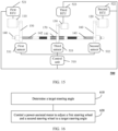
- FIG. 16 is a flowchart of a control method according to an embodiment of this application. The method shown in FIG. 16 includes step 610 and step 620.
- Step 610 Determine a target steering angle of a first steering wheel and a target steering angle of a second steering wheel.
- the target steering angle of the first steering wheel and the target steering angle of the second steering wheel are calculated based on an advanced driver assistance system (advanced driver assistance system, ADAS) or a steering operation of a user.
- advanced driver assistance system advanced driver assistance system
- ADAS advanced driver assistance system
- Step 620 A control unit controls a power-assisted motor to adjust the first steering wheel and the second steering wheel to a corresponding target steering angle.
- a first working mode When a first power-assisted motor in an independent steering mechanism is faulty, a first working mode may be enabled.
- the control unit controls a third power-assisted motor to adjust a length of a middle tie rod in the independent steering mechanism, and controls a second power-assisted motor to adjust a position of the middle tie rod, so that the middle tie rod drives the first steering wheel and the second steering wheel to rotate to the corresponding target steering angle.
- a second working mode may be enabled.
- the control unit controls the third power-assisted motor to adjust the length of a middle tie rod in the independent steering mechanism, and controls the first power-assisted motor to adjust the position of the middle tie rod, so that the middle tie rod drives the first steering wheel and the second steering wheel to rotate to the corresponding target steering angle.
- a third working mode may be enabled.
- the control unit controls the first power-assisted motor and the second power-assisted motor to adjust the length of the middle tie rod and the position of the middle tie rod, so that the middle tie rod drives the first steering wheel and the second steering wheel to rotate to the corresponding target steering angle.
- control unit controls the first power-assisted motor and the second power-assisted motor to adjust the length of the middle tie rod, and the position of the middle tie rod may be understood as that the control unit controls the first power-assisted motor and the second power-assisted motor to adjust positions of the first connecting rod and the second connecting rod.
- the method may further include: A first ECU may send first information to the control unit, and the first information may be used to indicate whether the first power-assisted motor is faulty.
- a second ECU may send second information to the control unit, and the second information may be used to indicate whether the second power-assisted motor is faulty.
- a third ECU may send third information to the control unit, and the third information may be used to indicate whether the third power-assisted motor is faulty.
- the first information may be further used to indicate whether the first ECU is faulty. It should be understood that because the first ECU is configured to control the first power-assisted motor, when the first ECU is faulty, the first power-assisted motor cannot be controlled to output torque, and it may be considered that the first power-assisted motor is faulty.
- the second information may be further used to indicate whether the second ECU is faulty. It should be understood that, because the second ECU is configured to control the second power-assisted motor, when the second ECU is faulty, the second power-assisted motor cannot be controlled to output torque, and it may be considered that the second power-assisted motor is faulty.
- the third information may be further used to indicate whether the third ECU is faulty. It should be understood that, because the third ECU is configured to control the third power-assisted motor, when the third ECU is faulty, the third power-assisted motor cannot be controlled to output torque, and it may be considered that the third power-assisted motor is faulty.
- a first sensor may send fourth information to the control unit, and the fourth information may be used to indicate current position information of the first connecting rod.
- a second sensor may send fifth information to the control unit, and the fifth information may be used to indicate current position information of the second connecting rod.
- a third sensor may send sixth information to the control unit, and the sixth information may be used to indicate current length information of the middle tie rod.
- the fourth information may be further used to indicate whether the first sensor is faulty. It should be understood that when the first sensor is faulty, the control unit cannot determine the position information of the first connecting rod. Therefore, the control unit cannot accurately control the first power-assisted motor to output torque, and it may be considered that the first power-assisted motor is faulty.
- the fifth information may be further used to indicate whether the second sensor is faulty. It should be understood that when the second sensor is faulty, the control unit cannot determine the position information of the second connecting rod. Therefore, the control unit cannot accurately control the second power-assisted motor to output torque, and it may be considered that the second power-assisted motor is faulty.
- the sixth information may be further used to indicate whether the third sensor is faulty. It should be understood that when the third sensor is faulty, the control unit cannot determine the length information of the middle tie rod. Therefore, the control unit cannot accurately control the third power-assisted motor to output torque, and it may be considered that the third power-assisted motor is faulty.
- FIG. 17 is a schematic diagram of a method for determining different working modes according to an embodiment of this application.
- Step 710 A control unit determines whether a first power-assisted motor is faulty.
- Step 720 is performed if the first power-assisted motor is not faulty.
- Step 740 is performed if the first power-assisted motor is faulty.
- control unit determines whether the first power-assisted motor is faulty may include determining whether the first power-assisted motor, a corresponding first ECU, and a corresponding first sensor are faulty.
- control unit may determine, based on first information sent by the first ECU, whether the first power-assisted motor and the first ECU are faulty.
- control unit may determine, based on fourth information sent by the first sensor, whether the first sensor is faulty.
- Step 720 The control unit determines whether a second power-assisted motor is faulty.
- Step 730 is performed if the second power-assisted motor is faulty.
- control unit determines whether the second power-assisted motor is faulty may include determining whether the second power-assisted motor, a corresponding second ECU, and a corresponding second sensor are faulty.
- control unit may determine, based on second information sent by the second ECU, whether the second power-assisted motor and the second ECU are faulty.
- control unit may determine, based on fifth information sent by the second sensor, whether the second sensor is faulty.
- Step 730 The control unit determines whether a third power-assisted motor is faulty.
- the control unit determines that a current working mode is a second working mode. If the third power-assisted motor is faulty, the control unit determines that a current working mode is a failure mode, that is, two of the three power-assisted motors are faulty and cannot perform steering.
- control unit determines whether the third power-assisted motor is faulty may include determining whether the third power-assisted motor, a corresponding third ECU, and a corresponding third sensor are faulty.
- control unit may determine, based on third information sent by the third ECU, whether the third power-assisted motor and the third ECU are faulty.
- control unit may determine, based on sixth information sent by the third sensor, whether the third sensor is faulty.
- Step 740 The control unit determines whether the second power-assisted motor is faulty.
- Step 750 is performed if the second power-assisted motor is not faulty. If the second power-assisted motor is faulty, the control unit determines that a current working mode is a failure mode.
- Step 750 The control unit determines whether the third power-assisted motor is faulty.
- the control unit determines that a current working mode is a first working mode. If the third power-assisted motor is faulty, the control unit determines that a current working mode is a failure mode.
- Table 1 shows a correspondence between each working mode and a working state of each power-assisted motor.
- Table 1 First power-assisted motor Second power-assisted motor Third power-assisted motor First working mode ⁇ ⁇ ⁇ Second working mode ⁇ ⁇ ⁇ Third working mode ⁇ ⁇ / Failure mode ⁇ ⁇ / ⁇ / ⁇ / ⁇ ⁇
- ⁇ indicates that the power-assisted motor works properly, ⁇ indicates that the power-assisted motor is faulty, and / indicates that the power-assisted motor is in any state.
- FIG. 18 is a schematic flowchart of controlling a power-assisted motor by a control unit according to an embodiment of this application.
- Step 810 Determine a target position of a first connecting rod and a target position of a second connecting rod.
- a control unit determines the target position of the first connecting rod and the target position of the second connecting rod based on a target steering angle of a first steering wheel and a target steering angle of a second steering wheel, that is, when the first connecting rod and the second connecting rod are in target positions, the first steering wheel and the second steering wheel may reach target steering angles, so that a vehicle completes steering.
- Step 820 Determine a target length of a middle tie rod.
- the control unit determines the target length of the middle tie rod based on the target position of the first connecting rod and the target position of the second connecting rod.
- Step 830 Determine a target rotation angle of a third connecting rod.
- the control unit may calculate the target rotation angle of the third connecting rod based on the target length of the middle tie rod. Because the third connecting rod is connected to the first connecting rod and the second connecting rod through screw threads, when the third connecting rod rotates, the first connecting rod and the second connecting rod approach or move away from each other along an axial direction of the middle tie rod, to adjust a length of the middle tie rod.
- Step 840 Control a power-assisted motor for adjustment.
- the control unit controls, based on the target rotation angle, a third power-assisted motor to adjust the length of the middle tie rod to the target length, and controls, based on the target position of the first connecting rod and the target position of the second connecting rod, a second power-assisted motor to adjust the first connecting rod and the second connecting rod to a corresponding target position.
- the control unit controls, based on the target rotation angle, the third power-assisted motor to adjust the length of the middle tie rod to the target length, and controls, based on the target position of the first connecting rod and the target position of the second connecting rod, a first power-assisted motor to adjust the first connecting rod and the second connecting rod to a corresponding target position.
- control unit may send a third control instruction to a third ECU, and the third control instruction is used to indicate the third ECU to control the third power-assisted motor to output torque, so that the length of the middle tie rod is the target length.
- the third ECU may control the third power-assisted motor according to the third control instruction.
- control unit may obtain a current length of the middle tie rod based on sixth information sent by a third sensor, and determine the third control instruction based on the current length and the target length of the middle tie rod.
- the control unit may send a first control instruction to a first ECU, and the first control instruction is used to indicate the first ECU to control the first power-assisted motor to output torque, so that the first connecting rod and the second connecting rod reach the corresponding target position.
- the first ECU may control the first power-assisted motor according to the first control instruction.
- control unit may obtain a current length of the middle tie rod based on fourth information sent by a first sensor, and determine a fourth control instruction based on the current length and the target length of the middle tie rod.
- control unit may send a second control instruction to a second ECU, and the second control instruction is used to indicate the second ECU to control the second power-assisted motor to output torque, so that the first connecting rod and the second connecting rod reach the corresponding target position.
- the second ECU may control the second power-assisted motor according to the second control instruction.
- control unit may obtain a current length of the middle tie rod based on fifth information sent by a second sensor, and determine the second control instruction based on the current length and the target length of the middle tie rod.
- step 810 to step 840 are processes corresponding to the first working mode and the second working mode. Because screw threads through which the third connecting rod is connected to the first connecting rod and the second connecting rod are of non-self-locking structures, the third connecting rod has no constraint effect on the first connecting rod and the second connecting rod. Therefore, when the control unit determines that a working mode is a third working mode, the control unit may control the first power-assisted motor and the second power-assisted motor to adjust the first connecting rod and the second connecting rod to a corresponding target position, that is, only step 810 and step 840 are required to complete a process of controlling the power-assisted motor.
- the control unit may send a first control instruction to a first ECU, and the first control instruction is used to indicate the first ECU to control the first power-assisted motor to output torque, so that the first connecting rod reaches the target position.
- the first ECU may control the first power-assisted motor according to the first control instruction.
- the control unit may send a second control instruction to a second ECU, and the second control instruction is used to indicate the second ECU to control the second power-assisted motor to output torque, so that the second connecting rod reaches the target position.
- the second ECU may control the second power-assisted motor according to the second control instruction.
- FIG 19 is a schematic diagram of a control apparatus according to an embodiment of this application.
- a control apparatus 2400 shown in FIG. 19 includes a generation unit 2410 and a sending unit 2420.
- the generation unit 2410 is configured to generate a control instruction, and the control instruction is used to control a power-assisted motor.
- the sending unit 2420 is configured to send the control instruction to an ECU corresponding to the power-assisted motor, and control the ECU to drive the corresponding power-assisted motor to output torque, to implement independent steering.
- the generation unit 2410 may be a processor 2520, the sending unit 2420 may be a communications interface 2530, and a specific structure of the control unit is shown in FIG. 20 .
- FIG. 20 is a schematic block diagram of a control unit according to another embodiment of this application.
- a control unit 2500 shown in FIG. 20 may include a memory 2510, a processor 2520, and a communications interface 2530.
- the memory 2510, the processor 2520, and the communications interface 2530 are connected through an internal connection path.
- the memory 2510 is configured to store instructions.
- the processor 2520 is configured to execute the instructions stored in the memory 2520, to control the communications interface 2530 to receive/send information.
- the memory 2510 may be coupled to the processor 2520 through an interface, or may be integrated with the processor 2520.
- the communications interface 2530 uses an apparatus such as but not limited to an input/output interface (input/output interface), to implement communication between the controller 2500 and another device or a communication network.
- an input/output interface input/output interface
- the steps in the foregoing method may be performed by using a hardware integrated logical circuit in the processor 2520, or by using instructions in a form of software.
- the method disclosed with reference to embodiments of this application may be directly performed by a hardware processor, or may be performed by using a combination of hardware in the processor and a software module.
- the software module may be located in a mature storage medium in the field, such as a random access memory, a flash memory, a read-only memory, a programmable read-only memory, an electrically erasable programmable memory, or a register.
- the storage medium is located in the memory 2510, and the processor 2520 reads information in the memory 2510 and completes the steps in the foregoing method in combination with hardware of the processor 2520. To avoid repetition, details are not described herein again.
- sequence numbers of the foregoing processes do not mean execution sequences.
- the execution sequences of the processes should be determined based on functions and internal logic of the processes, and should not constitute any limitation on implementation processes of embodiments of this application.
- the disclosed system, apparatus, and method may be implemented in other manners.
- the described apparatus embodiments are merely examples.
- division into the units is merely logical function division and may be other division in an actual implementation.
- a plurality of units or components may be combined or integrated into another system, or some features may be ignored or not performed.
- the displayed or discussed mutual couplings or direct couplings or communication connections may be implemented through some interfaces.
- the indirect couplings or communication connections between the apparatuses or units may be implemented in electrical, mechanical, or other forms.
- the units described as separate components may or may not be physically separate, and components displayed as units may or may not be physical units, may be located in one position, or may be distributed on a plurality of network units. Some or all of the units may be selected based on actual requirements to achieve the objectives of the solutions of embodiments.
- the functions When the functions are implemented in a form of a software functional unit and sold or used as an independent product, the functions may be stored in a computer-readable storage medium. Based on such an understanding, the technical solutions of this application essentially, or the part contributing to the conventional technology, or some of the technical solutions may be implemented in a form of a software product.
- the computer software product is stored in a storage medium, and includes several instructions for instructing a computer device (which may be a personal computer, a server, a network device, or the like) to perform all or some of the steps of the methods described in embodiments of this application.
- the foregoing storage medium includes any medium that can store program code, such as a USB flash drive, a removable hard disk, a read-only memory (read-only memory, ROM), a random access memory (random access memory, RAM), a magnetic disk, or an optical disc.
- program code such as a USB flash drive, a removable hard disk, a read-only memory (read-only memory, ROM), a random access memory (random access memory, RAM), a magnetic disk, or an optical disc.
Landscapes
- Engineering & Computer Science (AREA)
- Chemical & Material Sciences (AREA)
- Combustion & Propulsion (AREA)
- Transportation (AREA)
- Mechanical Engineering (AREA)
- Power Steering Mechanism (AREA)
- Steering Control In Accordance With Driving Conditions (AREA)
- Steering-Linkage Mechanisms And Four-Wheel Steering (AREA)
Abstract
Description
- This application claims priority to
Chinese Patent Application No. 202010884717.2, filed with the China National Intellectual Property Administration on August 28, 2020 - This application relates to the vehicle field, and more specifically, to an independent steering mechanism, a steering system, and a control method in a vehicle.
- When a vehicle is steered, steering angles of left and right steering wheels are different because steering radii of the left and right steering wheels are different. A steering mechanism is designed according to Ackermann (Ackermann) steering geometry, so that a steering angle of an inner wheel is 2 to 4 degrees greater than a steering angle of an outer wheel during steering of the vehicle, so that the vehicle can be steered smoothly.
- To implement a more flexible steering function of a vehicle, a steer-by-wire technology can be applied to a steering system of the vehicle. A conventional vehicle steering system is a mechanical system, and a vehicle steering motion is implemented by manipulating a driving wheel by a driver and transferring the manipulation to steering wheels through a steering gear and a series of rods. For the steer-by-wire technology, a mechanical connection between the driving wheel and the steering wheels is cancelled, and steering is implemented completely by electric energy. Further, left and right steering wheels can be controlled independently, which can better meet requirements of future vehicles and implement flexible steering. However, for the steer-by-wire independent technology, when one of steering motors respectively configured for the left and right steering wheels is faulty, overall steering needs to be recovered, and an independent steering function is lost.
- Embodiments of this application provide an independent steering mechanism, a steering system, and a control method. A plurality of power-assisted motors are disposed to implement an independent steering function, and resolve a problem that when one of the power-assisted motors is faulty, independent steering cannot be performed without changing a mechanical structure.
- According to a first aspect, an independent steering mechanism is provided, including: a first power-assisted motor, a second power-assisted motor, a third power-assisted motor, and a middle tie rod. The middle tie rod includes a first connecting rod, a second connecting rod, and a third connecting rod, and two ends of the third connecting rod are connected to the first connecting rod and the second connecting rod. The first power-assisted motor is configured to control the first connecting rod to move along an axial direction of the middle tie rod, the second power-assisted motor is configured to control the second connecting rod to move along the axial direction of the middle tie rod, and the third power-assisted motor is configured to control the third connecting rod to rotate, to drive the first connecting rod and the second connecting rod to approach or move away from each other along the axial direction of the middle tie rod.
- According to this embodiment of this application, the first power-assisted motor, the second power-assisted motor, and the third power-assisted motor may respectively control the first connecting rod, the second connecting rod, and the third connecting rod, to adjust a length and a position of the middle tie rod. In addition, when one of the three power-assisted motors is faulty, the length and the position of the middle tie rod can still be adjusted by using two power-assisted motors that work normally, without changing a mechanical structure.
- With reference to the first aspect, in some implementations of the first aspect, the third connecting rod is of a hollow structure, and the two ends of the third connecting rod are connected to the first connecting rod and the second connecting rod through screw threads.
- According to this embodiment of this application, the third connecting rod is of the hollow structure, and the two ends of the third connecting rod are connected to the first connecting rod and the second connecting rod through the screw threads. That is, the third connecting rod is of a socket structure, and one end of the first connecting rod and one end of the second connecting rod are respectively disposed in openings on two sides of the socket structure, and are connected through the screw threads. Alternatively, the first connecting rod and the second connecting rod may be of hollow structures, and the two ends of the third connecting rod are connected to the first connecting rod and the second connecting rod through ball screws or screw nuts. That is, the first connecting rod and the second connecting rod are of socket structures, and the two ends of the third connecting rod are respectively disposed in openings of one end of the first connecting rod and one end of the second connecting rod.
- With reference to the first aspect, in some implementations of the first aspect, the screw threads at the two ends of the third connecting rod are rotated in opposite directions.
- According to this embodiment of this application, when the screw threads disposed on the first connecting rod and the second connecting rod are rotated in opposite directions, the third motor controls the third connecting rod to rotate, so that the first connecting rod and the second connecting rod approach or move away from each other along the axial direction of the middle tie rod.
- With reference to the first aspect, in some implementations of the first aspect, the independent steering mechanism further includes a first transmission part, a second transmission part, and a third transmission part. The first power-assisted motor controls, by using the first transmission part, the first connecting rod to move along the axial direction of the middle tie rod, the second power-assisted motor controls, by using the second transmission part, the second connecting rod to move along the axial direction of the middle tie rod, and the third power-assisted motor controls, by using the third transmission part, the third connecting rod to rotate.
- According to this embodiment of this application, a rotational speed of the power-assisted motor is high, and the first transmission part, the second transmission part, and the third transmission part are all of transmission structures of deceleration. In this embodiment of this application, an example in which the first transmission part, the second transmission part, and the third transmission part are of belt transmission structures is used for description, but a structure of the transmission part is not limited. The first transmission part, the second transmission part, and the third transmission part may also be of a rack-and-pinion transmission structure, or may be of a worm-and-gear transmission structure, or may be of a transmission structure of parallel shaft gears.
- With reference to the first aspect, in some implementations of the first aspect, the first transmission part includes a first gear, and the first gear is connected to the first connecting rod through a screw thread. The first power-assisted motor drives the first gear to rotate, to control the first connecting rod to move along the axial direction of the middle tie rod.
- According to this embodiment of this application, a screw thread may be disposed on a surface on which the first connecting rod is in contact with the first gear, and an inner side (a surface on which the first gear is in contact with the first connecting rod) of the first gear may be of a screw nut or a ball screw structure. When the first power-assisted motor drives the first gear to rotate, the screw nut or the ball screw structure of the first gear is combined with the screw thread structure of the first connecting rod to drive the first connecting rod to move along the axial direction of the middle tie rod. A tooth may be disposed on an outer side (a surface on which the first gear is in contact with a first transmission belt) of the first gear, and may be meshed with a tooth disposed on an inner side (a surface on which the first transmission belt is in contact with the first gear) of the first transmission belt, to improve power transmission efficiency.
- With reference to the first aspect, in some implementations of the first aspect, the second transmission part includes a second gear, and the second gear is connected to the second connecting rod through a screw thread; and the second power-assisted motor drives the second gear to rotate, to control the second connecting rod to move along the axial direction of the middle tie rod.
- According to this embodiment of this application, a screw thread may be disposed on a surface on which the second connecting rod is in contact with the second gear, and an inner side (a surface on which the second gear is in contact with the second connecting rod) of the second gear may be of a screw nut or a ball screw structure. When the second power-assisted motor drives the second gear to rotate, the screw nut or the ball screw structure of the second gear is combined with the screw thread structure of the second connecting rod to drive the second connecting rod to move along the axial direction of the middle tie rod. A tooth may be disposed on an outer side (a surface on which the second gear is in contact with a second transmission belt) of the second gear, and may be meshed with a tooth disposed on an inner side (a surface on which the second transmission belt is in contact with the second gear) of the second transmission belt, to improve power transmission efficiency.
- With reference to the first aspect, in some implementations of the first aspect, the third transmission part includes a third gear. A guiding boss disposed along the axial direction of the middle tie rod is disposed on a surface of the third connecting rod. A guiding groove corresponding to the guiding boss is disposed on the third gear. The third gear is connected to the third connecting rod through the guiding groove and the guiding boss. The third power-assisted motor drives the third gear to rotate, to control the third connecting rod to rotate.
- According to this embodiment of this application, a guiding boss may be disposed on a surface on which the third connecting rod is in contact with the third gear, and a guiding groove corresponding to the guiding boss may be disposed on an inner side (a surface on which the third gear is in contact with the third connecting rod) of the third gear. The guiding boss may be disposed along the axial direction of the middle tie rod, so that efficiency of power transmission between the third gear and the third connecting rod can be improved. In addition, disposing of the guiding boss does not affect movement of the third connecting rod along the axial direction of the middle tie rod.
- Optionally, a tooth may be disposed on an outer side (a surface on which a
third gear 172 is in contact with a third transmission belt 171) of thethird gear 172, and may be meshed with a tooth disposed on an inner side (a surface on which thethird transmission belt 171 is in contact with the third gear 172) of thethird transmission belt 171, to improve power transmission efficiency. - According to a second aspect, an independent steering system is provided, including: a first steering wheel, a second steering wheel, and the independent steering mechanism according to any one of the possible implementations of the first aspect. The first connecting rod in the independent steering mechanism is connected to the first steering wheel, and the second connecting rod in the independent steering mechanism is connected to the second steering wheel. The first power-assisted motor in the independent steering mechanism is configured to control the first connecting rod to move along the axial direction of the middle tie rod in the independent steering mechanism, to enable the first steering wheel to rotate, and the second power-assisted motor in the independent steering mechanism is configured to control the second connecting rod to move along the axial direction of the middle tie rod in the independent steering mechanism, to enable the second steering wheel to rotate.
- With reference to the second aspect, in some implementations of the second aspect, the independent steering system further includes: a first steering knuckle, a second steering knuckle, a first steering kingpin, and a second steering kingpin. The first steering wheel is connected to the first steering kingpin through the first steering knuckle, the first steering knuckle is connected to the first connecting rod, and the first power-assisted motor is configured to control the first connecting rod to move along the axial direction of the middle tie rod, to enable the first steering knuckle to drive the first steering wheel to rotate around the first steering kingpin. The second steering wheel is connected to the second steering kingpin through the second steering knuckle, the second steering knuckle is connected to the second connecting rod, and the second power-assisted motor is configured to control the second connecting rod to move along the axial direction of the middle tie rod, to enable the second steering knuckle to drive the second steering wheel to rotate around the second steering kingpin.
- With reference to the second aspect, in some implementations of the second aspect, the independent steering system further includes a first tie rod and a second tie rod. One end of the first tie rod is connected to the first connecting rod, and the other end of the first tie rod is connected to the first steering knuckle. One end of the second tie rod is connected to the second connecting rod, and the other end of the second tie rod is connected to the second steering knuckle.
- With reference to the second aspect, in some implementations of the second aspect, the independent steering system further includes a control unit. The control unit is configured to determine a target steering angle of the first steering wheel and a target steering angle of the second steering wheel. When the first power-assisted motor or the second power-assisted motor is faulty, the control unit is configured to: control the third power-assisted motor in the independent steering mechanism to adjust a length of the middle tie rod in the independent steering mechanism; and control a normal power-assisted motor in the first power-assisted motor or the second power-assisted motor to adjust a position of the middle tie rod, so that the middle tie rod drives the first steering wheel and the second steering wheel to rotate to a corresponding target steering angle.
- With reference to the second aspect, in some implementations of the second aspect, when the first power-assisted motor and the second power-assisted motor are normal, the control unit is specifically configured to: control the first power-assisted motor and the second power-assisted motor to adjust the length of the middle tie rod and the position of the middle tie rod, so that the middle tie rod drives the first steering wheel and the second steering wheel to rotate to the corresponding target steering angle.
- With reference to the second aspect, in some implementations of the second aspect, the independent steering system includes: a first electronic control unit ECU, a second ECU, and a third ECU. The control unit is specifically configured to: send a first control instruction to the first ECU, where the first ECU is configured to control the first power-assisted motor according to the first control instruction; send a second control instruction to the second ECU, where the second ECU is configured to control the second power-assisted motor according to the second control instruction; and send a third control instruction to the third ECU, where the third ECU is configured to control the third power-assisted motor according to the third control instruction.
- With reference to the second aspect, in some implementations of the second aspect, the control unit is specifically configured to: determine a target position of the first connecting rod and a target position of the second connecting rod based on the target steering angle of the first steering wheel and the target steering angle of the second steering wheel; and determine a target length of the middle tie rod based on the target position of the first connecting rod and the target position of the second connecting rod. The control unit calculates a target rotation angle of the third connecting rod in the independent steering mechanism based on the target length; controls, based on the target rotation angle, the third power-assisted motor to adjust the length of the middle tie rod to the target length, and controls, based on the target position of the first connecting rod and the target position of the second connecting rod, the normal power-assisted motor in the first power-assisted motor or the second power-assisted motor to adjust the first connecting rod and the second connecting rod to a corresponding target position.
- With reference to the second aspect, in some implementations of the second aspect, the two ends of the third connecting rod are connected to the first connecting rod and the second connecting rod through the screw threads, and the target rotation angle satisfies the following formula:

L is the target length of the middle tie rod, L0 is a shortest length of the middle tie rod, and iang is a lead of the screw thread. - With reference to the second aspect, in some implementations of the second aspect, the control unit is specifically configured to: send the third control instruction to the third ECU, where the third control instruction is used to indicate the third ECU to control the third power-assisted motor to output torque, so that the length of the middle tie rod is the target length. The third ECU controls the third power-assisted motor according to the third control instruction.
- With reference to the second aspect, in some implementations of the second aspect, the control unit is specifically configured to: send the first control instruction to the first ECU, where the first control instruction is used to indicate the first ECU to control the first power-assisted motor to output torque, so that the first connecting rod and the second connecting rod rotate to the corresponding target position, or send the second control instruction to the second ECU, where the second control instruction is used to indicate the second ECU to control the second power-assisted motor to output torque, so that the first connecting rod and the second connecting rod reach the corresponding target position.
- With reference to the second aspect, in some implementations of the second aspect, the independent steering system further includes: a first sensor, a second sensor, and a third sensor. The first sensor is configured to determine position information of the first connecting rod, the second sensor is configured to determine position information of the second connecting rod; and the third sensor is configured to determine length information of the middle tie rod.
- With reference to the second aspect, in some implementations of the second aspect, the control unit is specifically configured to determine the first control instruction, the second control instruction, or the third control instruction based on the position information of the first connecting rod, the position information of the second connecting rod, and the length information of the middle tie rod.
- With reference to the second aspect, in some implementations of the second aspect, the first sensor is a translational position sensor or an angular position sensor.
- With reference to the second aspect, in some implementations of the second aspect, the second sensor is a translational position sensor or an angular position sensor.
- With reference to the second aspect, in some implementations of the second aspect, the third sensor is an angular position sensor.
- According to a third aspect, a control method for an independent steering system is provided. The independent steering system includes: a control unit, a first steering wheel, a second steering wheel, and the independent steering mechanism according to any one of the possible implementations of the first aspect. The first steering wheel and the second steering wheel are respectively connected to the first connecting rod and the second connecting rod of the middle tie rod in the independent steering mechanism, and the method includes: The control unit determines a target steering angle of the first steering wheel and a target steering angle of the second steering wheel. When the first power-assisted motor or the second power-assisted motor in the independent steering mechanism is faulty, the control unit controls the third power-assisted motor in the independent steering mechanism to adjust a length of the middle tie rod in the independent steering mechanism, and controls a normal power-assisted motor in the first power-assisted motor or the second power-assisted motor to adjust a position of the middle tie rod, so that the middle tie rod drives the first steering wheel and the second steering wheel to rotate to a corresponding target steering angle.
- With reference to the third aspect, in some implementations of the third aspect, the control method further includes: When the first power-assisted motor and the second power-assisted motor are normal, the control unit controls the first power-assisted motor and the second power-assisted motor to adjust the length of the middle tie rod and the position of the middle tie rod, so that the middle tie rod drives the first steering wheel and the second steering wheel to rotate to the corresponding target steering angle.
- With reference to the third aspect, in some implementations of the third aspect, the independent steering system includes: a first ECU, a second ECU, and a third ECU. The first ECU is configured to control the first power-assisted motor, the second ECU is configured to control the second power-assisted motor, and the third ECU is configured to control the third power-assisted motor. The method further includes: The control unit receives first information sent by the first ECU, where the first information is used to indicate whether the first power-assisted motor is faulty. The control unit receives second information sent by the second ECU, where the second information is used to indicate whether the second power-assisted motor is faulty. The control unit receives third information sent by the third ECU, where the third information is used to indicate whether the third power-assisted motor is faulty.
- With reference to the third aspect, in some implementations of the third aspect, that the control unit controls the third power-assisted motor in the independent steering mechanism to adjust a length of the middle tie rod in the independent steering mechanism, and controls a normal power-assisted motor in the first power-assisted motor or the second power-assisted motor to adjust a position of the middle tie rod includes: The control unit determines a target position of the first connecting rod and a target position of the second connecting rod based on the target steering angle of the first steering wheel and the target steering angle of the second steering wheel. The control unit determines a target length of the middle tie rod based on the target position of the first connecting rod and the target position of the second connecting rod. The control unit calculates a target rotation angle of the third connecting rod in the independent steering mechanism based on the target length. The control unit controls, based on the target rotation angle, the third power-assisted motor to adjust the length of the middle tie rod to the target length, and controls, based on the target position of the first connecting rod and the target position of the second connecting rod, the normal power-assisted motor in the first power-assisted motor or the second power-assisted motor to adjust the first connecting rod and the second connecting rod to a corresponding target position.
- With reference to the third aspect, in some implementations of the third aspect, the two ends of the third connecting rod are connected to the first connecting rod and the second connecting rod through the screw threads, and the target rotation angle satisfies the following formula:

L is the target length of the middle tie rod, L0 is a shortest length of the middle tie rod, and iang is a lead of the screw thread. - With reference to the third aspect, in some implementations of the third aspect, that the control unit controls, based on the target rotation angle, the third power-assisted motor to adjust the length of the middle tie rod to the target length includes: The control unit sends a third control instruction to the third ECU, where the third control instruction is used to indicate the third ECU to control the third power-assisted motor to output torque, so that the length of the middle tie rod is the target length; and the third ECU controls the third power-assisted motor according to the third control instruction.
- With reference to the third aspect, in some implementations of the third aspect, that the control unit controls, based on the target position of the first connecting rod and the target position of the second connecting rod, the normal power-assisted motor in the first power-assisted motor or the second power-assisted motor to adjust the first connecting rod and the second connecting rod to a corresponding target position includes: The control unit sends a first control instruction to the first ECU, where the first control instruction is used to indicate the first ECU to control the first power-assisted motor to output torque, so that the first connecting rod and the second connecting rod rotate to the corresponding target position. Alternatively, the control unit sends a second control instruction to the second ECU, where the second control instruction is used to indicate the second ECU to control the second power-assisted motor to output torque, so that the first connecting rod and the second connecting rod reach the corresponding target position.
- According to a fourth aspect, a vehicle is provided, including the independent steering system according to any one of the possible implementations of the second aspect. An independent steering mechanism in the independent steering system controls steering wheels to perform steering by adjusting a length and a position of a middle tie rod.
- According to a fifth aspect, a control apparatus is provided. The control apparatus includes a processing unit and a storage unit. The storage unit is configured to store instructions. The processing unit executes the instructions stored in the storage unit, so that the control apparatus performs any possible method according to the third aspect.
- Optionally, the control apparatus may be an independent controller in a vehicle, or may be a chip having a control function in the vehicle. The processing unit may be a processor. The storage unit may be a memory (for example, a register or cache) in the chip, or a storage unit (for example, a read-only memory or a random access memory) that is in the vehicle and that is located outside the chip.
- It should be noted that, in the foregoing controller, the memory is coupled to the processor. That the memory is coupled to the processor may be understood as that the memory is located inside the processor, or the memory is located outside the processor, to be independent of the processor.
- According to a sixth aspect, a computer program product is provided, the computer program product includes computer program code, and when the computer program code is run on a computer, the computer performs the method according to the foregoing aspects.
- It should be noted that all or some of the computer program code may be stored in a first storage medium. The first storage medium may be encapsulated together with a processor, or may be encapsulated separately from a processor. This is not specifically limited in embodiments of this application.
- According to a seventh aspect, a computer-readable medium is provided. The computer-readable medium stores program code. When the computer program code is run on a computer, the computer performs the method in the foregoing aspects.
-
-
FIG. 1 is a schematic diagram of conventional vehicle steering; -
FIG. 2 shows a steer-by-wire independent system according to the conventional technology; -
FIG. 3 shows an independent steering mechanism according to an embodiment of this application; -
FIG. 4 is a three-dimensional schematic diagram of an independent steering mechanism according to an embodiment of this application; -
FIG. 5 is a cross-sectional view of a third gear according to an embodiment of this application; -
FIG. 6 is a cross-sectional view of a third connecting rod according to an embodiment of this application; -
FIG. 7 is a schematic diagram of anindependent steering system 200 according to an embodiment of this application; -
FIG. 8 is a schematic diagram of common steering when a vehicle includes an independent steering system according to an embodiment of this application; -
FIG. 9 is a schematic diagram of in-situ steering when a vehicle includes two independent steering systems according to an embodiment of this application; -
FIG. 10 is a schematic diagram of vehicle translation according to an embodiment of this application; -
FIG. 11 is a schematic diagram of vehicle steering in a small radius according to an embodiment of this application; -
FIG. 12 is a schematic diagram corresponding to a failure of a third power-assisted motor according to an embodiment of this application; -
FIG. 13 is a schematic diagram corresponding to a failure of a first power-assisted motor according to an embodiment of this application; -
FIG. 14 is a schematic diagram corresponding to a failure of a second power-assisted motor according to an embodiment of this application; -
FIG. 15 is a schematic diagram of anotherindependent steering system 500 according to an embodiment of this application; -
FIG. 16 is a flowchart of a control method according to an embodiment of this application; -
FIG. 17 is a schematic diagram of a method for determining different working modes according to an embodiment of this application; -
FIG. 18 is a schematic flowchart of controlling a power-assisted motor by a control unit according to an embodiment of this application; -
FIG. 19 is a schematic diagram of a control unit according to an embodiment of this application; and -
FIG. 20 is a schematic block diagram of a control unit according to another embodiment of this application. - The following describes technical solutions of this application with reference to accompanying drawings.
-
FIG. 1 is a schematic diagram of conventional vehicle steering. - As shown in
FIG. 1 , when a vehicle is steered, steering angles of left and right steering wheels are different because steering radii of the left and right steering wheels are different. A steering mechanism is designed according to Ackermann steering geometry. When the vehicle turns along a curve, the steering angle of the inner wheel can be 2 to 4 degrees greater than the steering angle of the outer wheel by using equal cranks of four connecting rods, that is, a steering trapezoid shown inFIG. 1 . This structure allows centers of steering paths of four wheels of the vehicle to roughly intersect on an extension line of a rear axle, so that the vehicle turns smoothly. - A conventional steering system vehicle is a mechanical system, and a vehicle steering motion is implemented by manipulating a driving wheel by a driver and by transferring the manipulation to steering wheels through a steering gear and a series of rods. The conventional vehicle steering system is limited by a mechanical structure of the conventional vehicle steering system, and steering is not flexible. However, a vehicle steer-by-wire system cancels a mechanical connection between the driving wheel and the steering wheels, and steering is implemented completely by electric energy. Especially for a steer-by-wire independent system, steering motors are respectively configured for the left and right steering wheels, so that the left and right steering wheels can rotate independently, and therefore steering of the vehicle is more flexible.
-
FIG. 2 shows a steer-by-wire independent system in the conventional technology. - As shown in
FIG. 2 , a steering wheel 1 and asteering wheel 7 are respectively provided with asteering motor 2 and asteering motor 6. The two motors are independent of each other, and directly drive respectively corresponding steering wheels to perform steering. When one of thesteering motor 2 and thesteering motor 6 is faulty and stops working, arotating motor 4 may be used to control a left connecting piece 3 to connect to aright connecting piece 5, to change independent steering into overall steering. - For this structure, the steering motor may be used to directly drive the corresponding steering wheel to steer, and the rotating motor may be used to control separation and combination of left and right connecting pieces. However, when one of the steering motors is faulty, and when the
rotating motor 4 controls the connection of the left and right connecting pieces, normal steering is affected, and after the fault occurs, an independent steering capability is lost. - This application provides an independent steering mechanism, an independent steering system, and a control method. A plurality of power-assisted motors are disposed to implement an independent steering function, and resolve a problem that when one of the power-assisted motors is faulty, independent steering cannot be performed without changing a mechanical structure.
-
FIG. 3 shows an independent steering mechanism according to an embodiment of this application. - As shown in
FIG. 3 , anindependent steering mechanism 100 may include a first power-assistedmotor 110, a second power-assistedmotor 120, a third power-assistedmotor 130, and amiddle tie rod 140. - The
middle tie rod 140 includes a first connectingrod 142, a second connectingrod 143, and a third connectingrod 141. Two ends of the third connectingrod 141 are connected to the first connectingrod 142 and the second connectingrod 143. The first power-assistedmotor 110 is configured to control the first connectingrod 142 to move along an axial direction of themiddle tie rod 140. The second power-assistedmotor 120 is configured to control the second connectingrod 143 to move along the axial direction of themiddle tie rod 140. The third power-assistedmotor 130 is configured to control the third connectingrod 141 to rotate to drive the first connectingrod 142 and the second connectingrod 142 to move toward or opposite to each other along the axial direction of themiddle tie rod 140, and the first connectingrod 142 and the second connectingrod 142 approach or move away from each other along the axial direction of themiddle tie rod 140. - Optionally, the
independent steering mechanism 100 may further include afirst transmission part 150, asecond transmission part 160, and athird transmission part 170. The first power-assistedmotor 110 may control, by using thefirst transmission part 150, the first connectingrod 142 to move along an axial direction of themiddle tie rod 140. The second power-assistedmotor 120 may control, by using thesecond transmission part 160, the second connectingrod 143 to move along the axial direction of themiddle tie rod 140. The third power-assistedmotor 130 may control, by using thethird transmission part 170, the third connectingrod 141 to rotate. - Optionally, the third connecting
rod 141 is of a hollow structure, and the two ends of the third connectingrod 141 are connected to the first connectingrod 142 and the second connectingrod 143 through screw threads. That is, the third connectingrod 141 is of a socket structure, and one end of the first connectingrod 142 and one end of the second connectingrod 143 are respectively disposed in openings on two sides of the socket structure, and are connected through the screw threads. - Alternatively, the first connecting
rod 142 and the second connectingrod 143 may be of hollow structures, and the two ends of the third connectingrod 141 are connected to the first connectingrod 142 and the second connectingrod 143 through ball screws or screw nuts. That is, the first connectingrod 142 and the second connectingrod 143 are of socket structures, and the two ends of the third connectingrod 141 are respectively disposed in openings of one end of the first connectingrod 142 and one end of the second connectingrod 143. - It should be understood that, in this embodiment of this application, an example in which the third connecting
rod 141 is of the hollow structure is used for description, and specific structures of the first connectingrod 142, the second connectingrod 143, and the third connecting rod are not limited. -
FIG. 4 is a three-dimensional schematic diagram of an independent steering mechanism according to an embodiment of this application. - Optionally, as shown in
FIG. 4 , thefirst transmission part 150 may include afirst transmission belt 151 and afirst gear 152. Thefirst gear 152 has a central hole, and the first connectingrod 142 passes through thefirst gear 152 through the hole. When the first power-assistedmotor 110 rotates, thefirst transmission belt 151 may drive thefirst gear 152 to rotate, and further drive the first connectingrod 142 to move along the axial direction of themiddle tie rod 140. - Optionally, a screw thread may be disposed on a surface on which the first connecting
rod 142 is in contact with thefirst gear 152, and an inner side (a surface on which thefirst gear 152 is in contact with the first connecting rod 142) of thefirst gear 152 may be of a screw nut or a ball screw structure. When the first power-assistedmotor 110 drives thefirst gear 152 to rotate, the screw nut or the ball screw structure of thefirst gear 152 is combined with the screw thread structure of the first connectingrod 142 to drive the first connectingrod 142 to move along the axial direction of themiddle tie rod 140. - Optionally, a tooth may be disposed on an outer side (a surface on which the
first gear 152 is in contact with the first transmission belt 151) of thefirst gear 152, and may be meshed with a tooth disposed on an inner side (a surface on which thefirst transmission belt 151 is in contact with the first gear 152) of thefirst transmission belt 151, to improve power transmission efficiency. - Optionally, the
second transmission part 160 may include asecond transmission belt 161 and asecond gear 162. Thesecond gear 162 has a central hole, and the second connectingrod 143 passes through thesecond gear 162 through the hole. When the second power-assistedmotor 120 rotates, thesecond transmission belt 161 may drive thesecond gear 162 to rotate, and further drive the second connectingrod 143 to move along the axial direction of themiddle tie rod 140. - Optionally, a screw thread may be disposed on a surface on which the second connecting
rod 143 is in contact with thesecond gear 162, and an inner side (a surface on which thesecond gear 162 is in contact with the second connecting rod 143) of thesecond gear 162 may be of a screw nut or a ball screw structure. When the second power-assistedmotor 120 drives thesecond gear 162 to rotate, the screw nut or the ball screw structure of thesecond gear 162 is combined with the screw thread structure of the second connectingrod 143 to drive the second connectingrod 143 to move along the axial direction of themiddle tie rod 140. - Optionally, a tooth may be disposed on an outer side (a surface on which the
second gear 162 is in contact with the second transmission belt 161) of thesecond gear 162, and may be meshed with a tooth disposed on an inner side (a surface on which thesecond transmission belt 161 is in contact with the second gear 162) of thesecond transmission belt 161, to improve power transmission efficiency. - Optionally, the
third transmission part 170 may include athird transmission belt 171 and athird gear 172. Thethird gear 172 has a central hole, and the third connectingrod 141 passes through thethird gear 172 through the hole. When the third power-assistedmotor 130 rotates, thethird transmission belt 171 may drive thethird gear 172 to rotate, and further drive the third connectingrod 141 to rotate. - Optionally, a guiding
boss 173 may be disposed on a surface on which the third connectingrod 141 is in contact with thethird gear 172, and a guidinggroove 174 corresponding to the guidingboss 173 may be disposed on an inner side (a surface on which thethird gear 172 is in contact with the third connecting rod 141) of thethird gear 172, as shown inFIG. 5 . The guidingboss 173 may be disposed along the axial direction of themiddle tie rod 140, so that efficiency of power transmission between thethird gear 172 and the third connectingrod 141 can be improved. In addition, disposing of the guidingboss 173 does not affect movement of the third connectingrod 141 along the axial direction of themiddle tie rod 140. - Optionally, a tooth may be disposed on an outer side (a surface on which the
third gear 172 is in contact with the third transmission belt 171) of thethird gear 172, and may be meshed with a tooth disposed on an inner side (a surface on which thethird transmission belt 171 is in contact with the third gear 172) of thethird transmission belt 171, to improve power transmission efficiency. - Optionally, the
first transmission part 150 and thesecond transmission part 160 may be of non-self-locking structures. Thefirst transmission part 150 is used as an example. When the first connectingrod 142 moves, thefirst gear 152 may be driven to rotate. In addition, when thefirst gear 152 rotates, the first connectingrod 142 may be driven to move. It may also be correspondingly understood that thesecond transmission part 160 is of a non-self-locking structure. - It should be understood that, in this embodiment of this application, a rotational speed of the power-assisted motor is high, and the
first transmission part 150, thesecond transmission part 160, and thethird transmission part 170 are all of transmission structures of deceleration. In this embodiment of this application, an example in which thefirst transmission part 150, thesecond transmission part 160, and thethird transmission part 170 are of belt transmission structures is used for description, but a structure of the transmission part is not limited. Thefirst transmission part 150, thesecond transmission part 160, and thethird transmission part 170 may also be of a rack-and-pinion transmission structure, or may be of a worm-and-gear transmission structure, or may be of a transmission structure of parallel shaft gears. -
FIG. 6 is a cross-sectional view of a third connecting rod according to an embodiment of this application. - As shown in
FIG. 6 , the third connectingrod 141 may be connected to the first connectingrod 142 and the second connectingrod 143 through the screw threads. - Optionally, the screw threads disposed on the first connecting
rod 142 and the second connectingrod 143 are rotated in opposite directions. - When the screw threads disposed on the first connecting
rod 142 and the second connectingrod 143 are rotated in opposite directions, thethird motor 130 drives, by using thethird transmission part 170, the third connectingrod 141 to rotate, and the first connectingrod 142 and the second connectingrod 143 move toward or opposite to each other along the axial direction of themiddle tie rod 140. For example, when the third connectingrod 141 rotates in a first direction, the first connectingrod 142 and the second connectingrod 143 may move toward each other along the axial direction of themiddle tie rod 140, that is, the first connectingrod 142 and the second connectingrod 143 approach each other. When the third connectingrod 141 rotates in a second direction, the first connectingrod 142 and the second connectingrod 143 may move opposite to each other along the axial direction of themiddle tie rod 140, that is, the first connectingrod 142 and the second connectingrod 143 move away from each other. The first direction is opposite to the second direction. For example, the first direction may be a clockwise direction, and the second direction may be a counterclockwise direction. -
FIG. 7 is a schematic diagram of anindependent steering system 200 according to an embodiment of this application. Theindependent steering system 200 shown inFIG. 7 may be applied to a vehicle. - As shown in
FIG. 7 , theindependent steering system 200 may include theindependent steering mechanism 100, afirst steering wheel 221, and asecond steering wheel 222. - The
independent steering mechanism 100 may be any one of the independent steering mechanisms described in the foregoing embodiments, and may include: the first power-assistedmotor 110, the second power-assistedmotor 120, the third power-assistedmotor 130, and themiddle tie rod 140. Themiddle tie rod 140 includes the third connectingrod 141, the first connectingrod 142, and the second connectingrod 143. - The third power-assisted
motor 130 is configured to control the third connectingrod 141 to rotate to drive the first connectingrod 142 and the second connectingrod 142 to move along the axial direction of themiddle tie rod 140. - The first connecting
rod 142 may be connected to thefirst steering wheel 221, and the first power-assistedmotor 110 may be configured to control the first connectingrod 142 to move along the axial direction of themiddle tie rod 140, to enable thefirst steering wheel 221 to rotate. - The second connecting
rod 143 may be connected to thesecond steering wheel 222, and the second power-assistedmotor 120 may be configured to control the second connectingrod 142 to move along the axial direction of themiddle tie rod 140, to enable thesecond steering wheel 222 to rotate. - Optionally, the
independent steering system 200 may include afirst steering knuckle 201, asecond steering knuckle 202, afirst steering kingpin 211, and asecond steering kingpin 212. - The
first steering wheel 221 is connected to thefirst steering kingpin 211 through thefirst steering knuckle 201, and thefirst steering knuckle 201 is connected to the first connectingrod 142. The first power-assistedmotor 110 is configured to control the first connectingrod 142 to move along the axial direction of themiddle tie rod 140, to enable thefirst steering knuckle 201 to drive thefirst steering wheel 221 to rotate around thefirst steering kingpin 211. - The
second steering wheel 222 is connected to thesecond steering kingpin 212 through thesecond steering knuckle 202, and thesecond steering knuckle 202 is connected to the second connectingrod 143. The second power-assistedmotor 120 is configured to control the second connectingrod 143 to move along the axial direction of themiddle tie rod 140, to enable thesecond steering knuckle 202 to drive thesecond steering wheel 222 to rotate around thesecond steering kingpin 212. - Optionally, the
first steering kingpin 211 and thesecond steering kingpin 212 may be fastened on a chassis of the vehicle, to increase reliability when the steering wheel works. - Optionally, the
independent steering system 200 may include afirst tie rod 231 and asecond tie rod 232. Thefirst tie rod 231 may be configured to connect to the first connectingrod 142 and thefirst steering knuckle 201. Thesecond tie rod 232 may be configured to connect to the second connectingrod 143 and thesecond steering knuckle 202. - Optionally, the
independent steering system 200 may include afirst housing 241 and asecond housing 242. Thefirst housing 241 may be configured to accommodate a part of thefirst transmission part 150, for example, may accommodate the first gear in thefirst transmission part 150, to prevent the first gear from being exposed outside. Thesecond housing 242 may be configured to accommodate a part of thesecond transmission part 160. In addition, thefirst housing 241 and thesecond housing 242 may be configured to fasten theindependent steering system 200 on the chassis of the vehicle, to increase reliability of using theindependent steering system 200. - It should be understood that, because the first connecting
rod 142 and the second connectingrod 143 are respectively connected to thefirst steering knuckle 201 and thesecond steering knuckle 202, the first connectingrod 142 and the second connectingrod 143 are configured to drive thefirst steering wheel 221 and thesecond steering wheel 222 to rotate around thefirst steering kingpin 211 and thesecond steering kingpin 212, to enable the vehicle to steer. Therefore, the first connectingrod 142 and the second connectingrod 143 can only move along the axial direction of themiddle tie rod 140, and cannot rotate. - For the third connecting
rod 141, the third power-assistedmotor 130 may drive, by using thethird transmission part 170, the third connectingrod 141 to rotate, to drive the first connectingrod 142 and the second connectingrod 143 to move toward or opposite to each other along the axial direction of themiddle tie rod 140, and may control a length L of themiddle tie rod 140. In addition, when only the first power-assistedmotor 110 or the second power-assistedmotor 120 works, the third connectingrod 141 may drive the first connectingrod 142 or the second connectingrod 143 to move. The thirdconnecting rod 141 is used as a connecting piece between the first connectingrod 142 and the second connectingrod 143, and the third connectingrod 141 does not rotate when the connecting rod connected to only one end of the third connectingrod 141 moves. Therefore, when only the first power-assistedmotor 110 or the second power-assistedmotor 120 works, the third connectingrod 141 may drive themiddle tie rod 140 to move along the axial direction of themiddle tie rod 140. Therefore, the third connectingrod 141 may rotate, and may move along the axial direction of themiddle tie rod 140. -
FIG. 8 andFIG. 9 are schematic diagrams of vehicle steering according to an embodiment of this application. Working states of the independent steering system provided in this application in different turning cases are shown inFIG. 8 andFIG. 9 .FIG. 8 is a schematic diagram of common steering when a vehicle includes an independent steering system according to an embodiment of this application.FIG. 9 is a schematic diagram of in-situ steering when a vehicle includes two independent steering systems according to an embodiment of this application. - As shown in
FIG. 8 , the vehicle may include theindependent steering system 200. During common steering, left steering is used as an example. During steering, a steering angle of an inner steering wheel is greater than a steering angle of an outer steering wheel. The first power-assistedmotor 110 and the second power-assistedmotor 120 may respectively drive the first connectingrod 142 and the second connectingrod 143 to move to the left along the axial direction of themiddle tie rod 140. In this case, thethird motor 130 may be in a standby state, and does not output torque. Because the screw threads through which the third connectingrod 130 is connected to the first connectingrod 142 and the second connectingrod 143 are of non-self-locking structures, the third connectingrod 130 has no constraint effect on the first connectingrod 142 and the second connectingrod 143. Therefore, steering angles of thefirst steering wheel 221 and thesecond steering wheel 222 are independently controlled, and corresponding angles may be flexibly adjusted. - It should be understood that, when the vehicle includes two independent steering systems, during the common steering, rear wheels may remain still, and the common steering may be implemented in the foregoing manner.
- As shown in
FIG. 9 , a vehicle may include two independent steering systems. During in-situ steering, steering wheels of anindependent steering system 300 need to rotate to an inner side, and steering wheels of anindependent steering system 400 need to rotate to an outer side, so that a steering center of the vehicle is at a geometric center of the vehicle, and the vehicle can implement an in-situ steering function along a dashed line. - In a case in which the steering wheels of the
independent steering system 300 need to rotate to the inner side, a first power-assistedmotor 310 and a second power-assistedmotor 320 may respectively drive a first connectingrod 342 and a second connectingrod 343 to approach each other along the axial direction of themiddle tie rod 140. In this case, athird motor 330 may be in a standby state, and does not output torque. - In a case in which the steering wheels of the
independent steering system 400 need to rotate to the outer side, a first power-assistedmotor 410 and a second power-assistedmotor 420 may respectively drive a first connectingrod 442 and a second connectingrod 443 to move away from each other along the axial direction of themiddle tie rod 140. In this case, athird motor 430 may be in a standby state, and does not output torque. -
FIG. 10 andFIG. 11 are schematic diagrams of steering when a vehicle includes two independent steering systems according to an embodiment of this application.FIG. 10 is a schematic diagram of vehicle translation according to an embodiment of this application.FIG. 11 is a schematic diagram of vehicle steering with a small radius according to an embodiment of this application. - As shown in
FIG. 10 , during translation, steering angles of four steering wheels of a vehicle are the same. In this case, the vehicle may translate, and a steering center of the vehicle is at an infinite distance. - As shown in
FIG. 11 , during steering in a small radius, front side steering wheels of a vehicle are steered, rear side steering wheels on a rear side assist in the steering, and a steering angle of the rear side steering wheels is opposite to a steering angle of the front side steering wheels. In this case, a steering center of the vehicle can be very close to the vehicle body compared with the common steering, and a turning radius is greatly reduced. - It should be understood that the independent steering system provided in embodiments of this application includes the independent steering mechanism whose length is adjustable. Independent steering of two steering wheels can be implemented by controlling the first power-assisted motor, the second power-assisted motor, and the third power-assisted motor. When two independent steering systems are used, the vehicle can implement functions such as translational steering, turning radius reduction, and in-situ steering, to make driving modes more diversified.
- According to the independent steering system provided in embodiments of this application, when one of the power-assisted motors is faulty, the independent steering system can still implement an independent steering function without a structural adjustment. With reference to
FIG. 12 to FIG. 14 , the following describes a working state of the independent steering system when the power-assisted motor is faulty. -
FIG. 12 is a schematic diagram corresponding to a failure of the third power-assistedmotor 130 in the independent steering system. Because the screw threads through which the third connectingrod 130 is connected to the first connectingrod 142 and the second connectingrod 143 are of non-self-locking structures, and the third connectingrod 130 has no constraint effect on the first connectingrod 142 and the second connectingrod 143, when the third power-assistedmotor 130 is faulty, the first power-assistedmotor 110 and the second power-assistedmotor 120 may independently control steering angles of corresponding steering wheels. -
FIG. 13 is a schematic diagram corresponding to a failure of the first power-assistedmotor 110 in the independent steering system. When the first power-assistedmotor 110 is faulty, the third power-assistedmotor 130 may control the length L of themiddle tie rod 140, and the second power-assistedmotor 120 drives themiddle tie rod 140 to move along the axial direction of themiddle tie rod 140, to implement independent steering of two steering wheels. It should be understood that, compared with working of the first power-assistedmotor 110 and the second power-assistedmotor 120, a 50% power-assisted capability can be provided in this case. -
FIG. 14 is a schematic diagram corresponding to a failure of the second power-assistedmotor 120 in the independent steering system. When the second power-assistedmotor 120 is faulty, the third power-assistedmotor 130 may control the length L of themiddle tie rod 140, and the first power-assistedmotor 110 drives themiddle tie rod 140 to move along the axial direction of themiddle tie rod 140, to implement independent steering of two steering wheels. It should be understood that, compared with working of the first power-assistedmotor 110 and the second power-assistedmotor 120, a 50% power-assisted capability can be provided in this case. - It should be understood that the independent steering system provided in this embodiment of this application can implement independent steering of two steering wheels by controlling the steering wheels by the first power-assisted motor, the second power-assisted motor, and the third power-assisted motor. In addition, a driving posture of a vehicle may be corrected by adjusting a single steering wheel, to ensure good operation stability of the vehicle. When the vehicle includes two independent steering systems, four-wheel steering can be applied to the vehicle, to implement functions such as translational steering, turning radius reduction, and in-situ steering. When any one of the power-assisted motors in the independent steering system fails, the other two power-assisted motors can still work together to implement independent steering. In addition, when the power-assisted motor fails, the independent steering system can continue to respond to a steering operation of a user without a structural adjustment, to ensure steering safety of the vehicle. The independent steering system provided in this embodiment of this application does not require components such as a clutch, and has a simpler structure.
-
FIG. 15 is a schematic diagram of anotherindependent steering system 500 according to an embodiment of this application. Theindependent steering system 500 shown inFIG. 15 may be applied to a vehicle. - As shown in
FIG. 15 , theindependent steering system 500 may further include: acontrol unit 510, a first electronic control unit (electronic control unit, ECU) 521, asecond ECU 522, and athird ECU 523. - The
first ECU 521 may be configured to control the first power-assistedmotor 110. Thesecond ECU 522 may be configured to control the second power-assistedmotor 120. Thethird ECU 523 may be configured to control the third power-assistedmotor 130. Thecontrol unit 510 may send a corresponding first control instruction, second control instruction, and third control instruction to thefirst ECU 521, thesecond ECU 522, and thethird ECU 523. Thefirst ECU 521, thesecond ECU 522, and thethird ECU 523 may separately control, according to the first control instruction, the second control instruction, and the third control instruction, corresponding power-assisted motors to output torque. - Optionally, the control instruction may include output torque instructions corresponding to the first power-assisted
motor 110, the second power-assistedmotor 120, or the third power-assistedmotor 130. - Optionally, the
independent steering system 500 may further include afirst sensor 531, asecond sensor 532, and athird sensor 533. Thefirst sensor 531 may be configured to determine position information of the first connectingrod 142. Thesecond sensor 532 may be configured to determine position information of the second connectingrod 143. Thethird sensor 533 may be configured to determine length information of themiddle tie rod 140. - Optionally, the
first sensor 531, thesecond sensor 532, and thethird sensor 533 may send the determined information to thecontrol unit 510. Thecontrol unit 510 may determine the first control instruction, the second control instruction, or the third control instruction based on current position information of the first connectingrod 142, current position information of the second connectingrod 143, and current length information of themiddle tie rod 140. - Optionally, the
first sensor 531 may be a translational position sensor or an angular position sensor. When thefirst sensor 531 is the translational position sensor, a specific position of the first connectingrod 142 may be directly measured. When thefirst sensor 531 is the angular position sensor, a specific position of the first connectingrod 142 may be calculated by measuring an angular position of the first power-assistedmotor 110 or an angular position of the first gear in thefirst transmission part 150. - Optionally, the
second sensor 532 may be a translational position sensor or an angular position sensor. When thesecond sensor 532 is the translational position sensor, a specific position of the second connectingrod 143 may be directly measured. When thesecond sensor 532 is the angular position sensor, a specific position of the second connectingrod 143 may be calculated by measuring an angular position of the second power-assistedmotor 120 or an angular position of the second gear in thesecond transmission part 160. - Optionally, the
third sensor 533 may be an angular sensor. Thethird sensor 533 may determine a length of themiddle tie rod 140 by measuring a rotation angle of the third connectingrod 141. It should be understood that, because there is a non-self-locking structure between the first connectingrod 142, the second connectingrod 143, and the third connectingrod 141, when the third connectingrod 141 rotates, the first connectingrod 142 and the second connectingrod 143 approach or move away from each other along the axial direction of themiddle tie rod 140, that is, the rotation angle of the third connectingrod 141 corresponds to the length of themiddle tie rod 140. Therefore, the length of themiddle tie rod 140 may be determined by measuring the rotation angle of the third connectingrod 141. - The independent steering mechanism and the independent steering system provided in embodiments of this application are described above with reference to
FIG. 3 to FIG. 15 . The following describes a control method in embodiments of this application with reference toFIG. 16 to FIG. 18 . It should be noted that the control method in embodiments of this application may be applied to any apparatus described above, and this is not limited in embodiments of this application. -
FIG. 16 is a flowchart of a control method according to an embodiment of this application. The method shown inFIG. 16 includesstep 610 andstep 620. - Step 610: Determine a target steering angle of a first steering wheel and a target steering angle of a second steering wheel.
- The target steering angle of the first steering wheel and the target steering angle of the second steering wheel are calculated based on an advanced driver assistance system (advanced driver assistance system, ADAS) or a steering operation of a user.
- Step 620: A control unit controls a power-assisted motor to adjust the first steering wheel and the second steering wheel to a corresponding target steering angle.
- When a first power-assisted motor in an independent steering mechanism is faulty, a first working mode may be enabled. The control unit controls a third power-assisted motor to adjust a length of a middle tie rod in the independent steering mechanism, and controls a second power-assisted motor to adjust a position of the middle tie rod, so that the middle tie rod drives the first steering wheel and the second steering wheel to rotate to the corresponding target steering angle.
- When the second power-assisted motor in the independent steering mechanism is faulty, a second working mode may be enabled. The control unit controls the third power-assisted motor to adjust the length of a middle tie rod in the independent steering mechanism, and controls the first power-assisted motor to adjust the position of the middle tie rod, so that the middle tie rod drives the first steering wheel and the second steering wheel to rotate to the corresponding target steering angle.
- Optionally, when the first power-assisted motor and the second power-assisted motor are normal, a third working mode may be enabled. The control unit controls the first power-assisted motor and the second power-assisted motor to adjust the length of the middle tie rod and the position of the middle tie rod, so that the middle tie rod drives the first steering wheel and the second steering wheel to rotate to the corresponding target steering angle. It should be understood that because screw threads through which a third connecting rod is connected to a first connecting rod and a second connecting rod are of non-self-locking structures, the third connecting rod has no constraint effect on the first connecting rod and the second connecting rod. Therefore, that the control unit controls the first power-assisted motor and the second power-assisted motor to adjust the length of the middle tie rod, and the position of the middle tie rod may be understood as that the control unit controls the first power-assisted motor and the second power-assisted motor to adjust positions of the first connecting rod and the second connecting rod.
- Optionally, the method may further include: A first ECU may send first information to the control unit, and the first information may be used to indicate whether the first power-assisted motor is faulty. A second ECU may send second information to the control unit, and the second information may be used to indicate whether the second power-assisted motor is faulty. A third ECU may send third information to the control unit, and the third information may be used to indicate whether the third power-assisted motor is faulty.
- Optionally, the first information may be further used to indicate whether the first ECU is faulty. It should be understood that because the first ECU is configured to control the first power-assisted motor, when the first ECU is faulty, the first power-assisted motor cannot be controlled to output torque, and it may be considered that the first power-assisted motor is faulty.
- Optionally, the second information may be further used to indicate whether the second ECU is faulty. It should be understood that, because the second ECU is configured to control the second power-assisted motor, when the second ECU is faulty, the second power-assisted motor cannot be controlled to output torque, and it may be considered that the second power-assisted motor is faulty.
- Optionally, the third information may be further used to indicate whether the third ECU is faulty. It should be understood that, because the third ECU is configured to control the third power-assisted motor, when the third ECU is faulty, the third power-assisted motor cannot be controlled to output torque, and it may be considered that the third power-assisted motor is faulty.
- Optionally, a first sensor may send fourth information to the control unit, and the fourth information may be used to indicate current position information of the first connecting rod. A second sensor may send fifth information to the control unit, and the fifth information may be used to indicate current position information of the second connecting rod. A third sensor may send sixth information to the control unit, and the sixth information may be used to indicate current length information of the middle tie rod.
- Optionally, the fourth information may be further used to indicate whether the first sensor is faulty. It should be understood that when the first sensor is faulty, the control unit cannot determine the position information of the first connecting rod. Therefore, the control unit cannot accurately control the first power-assisted motor to output torque, and it may be considered that the first power-assisted motor is faulty.
- Optionally, the fifth information may be further used to indicate whether the second sensor is faulty. It should be understood that when the second sensor is faulty, the control unit cannot determine the position information of the second connecting rod. Therefore, the control unit cannot accurately control the second power-assisted motor to output torque, and it may be considered that the second power-assisted motor is faulty.
- Optionally, the sixth information may be further used to indicate whether the third sensor is faulty. It should be understood that when the third sensor is faulty, the control unit cannot determine the length information of the middle tie rod. Therefore, the control unit cannot accurately control the third power-assisted motor to output torque, and it may be considered that the third power-assisted motor is faulty.
- It should be understood that, according to the control method provided in this embodiment of this application, different working modes may be selected based on an actual situation. When the three power-assisted motors work normally, two steering wheels in an independent steering system may be controlled to implement independent steering. In addition, when any one of the three power-assisted motors is faulty, independent steering can be implemented without changing a mechanical structure of the independent steering system, which is more efficient.
-
FIG. 17 is a schematic diagram of a method for determining different working modes according to an embodiment of this application. - Step 710: A control unit determines whether a first power-assisted motor is faulty.
- Step 720 is performed if the first power-assisted motor is not faulty. Step 740 is performed if the first power-assisted motor is faulty.
- Optionally, that the control unit determines whether the first power-assisted motor is faulty may include determining whether the first power-assisted motor, a corresponding first ECU, and a corresponding first sensor are faulty.
- Optionally, the control unit may determine, based on first information sent by the first ECU, whether the first power-assisted motor and the first ECU are faulty.
- Optionally, the control unit may determine, based on fourth information sent by the first sensor, whether the first sensor is faulty.
- Step 720: The control unit determines whether a second power-assisted motor is faulty.
- If the second power-assisted motor is not faulty, the control unit determines that a current working mode is a third working mode. Step 730 is performed if the second power-assisted motor is faulty.
- Optionally, that the control unit determines whether the second power-assisted motor is faulty may include determining whether the second power-assisted motor, a corresponding second ECU, and a corresponding second sensor are faulty.
- Optionally, the control unit may determine, based on second information sent by the second ECU, whether the second power-assisted motor and the second ECU are faulty.
- Optionally, the control unit may determine, based on fifth information sent by the second sensor, whether the second sensor is faulty.
- Step 730: The control unit determines whether a third power-assisted motor is faulty.
- If the third power-assisted motor is not faulty, the control unit determines that a current working mode is a second working mode. If the third power-assisted motor is faulty, the control unit determines that a current working mode is a failure mode, that is, two of the three power-assisted motors are faulty and cannot perform steering.
- Optionally, that the control unit determines whether the third power-assisted motor is faulty may include determining whether the third power-assisted motor, a corresponding third ECU, and a corresponding third sensor are faulty.
- Optionally, the control unit may determine, based on third information sent by the third ECU, whether the third power-assisted motor and the third ECU are faulty.
- Optionally, the control unit may determine, based on sixth information sent by the third sensor, whether the third sensor is faulty.
- Step 740: The control unit determines whether the second power-assisted motor is faulty.
- Step 750 is performed if the second power-assisted motor is not faulty. If the second power-assisted motor is faulty, the control unit determines that a current working mode is a failure mode.
- Step 750: The control unit determines whether the third power-assisted motor is faulty.
- If the third power-assisted motor is not faulty, the control unit determines that a current working mode is a first working mode. If the third power-assisted motor is faulty, the control unit determines that a current working mode is a failure mode.
- Table 1 shows a correspondence between each working mode and a working state of each power-assisted motor.
Table 1 First power-assisted motor Second power-assisted motor Third power-assisted motor First working mode × √ √ Second working mode √ × √ Third working mode √ √ / Failure mode × × / × / × / × × - √ indicates that the power-assisted motor works properly, × indicates that the power-assisted motor is faulty, and / indicates that the power-assisted motor is in any state.
-
FIG. 18 is a schematic flowchart of controlling a power-assisted motor by a control unit according to an embodiment of this application. - Step 810: Determine a target position of a first connecting rod and a target position of a second connecting rod.
- A control unit determines the target position of the first connecting rod and the target position of the second connecting rod based on a target steering angle of a first steering wheel and a target steering angle of a second steering wheel, that is, when the first connecting rod and the second connecting rod are in target positions, the first steering wheel and the second steering wheel may reach target steering angles, so that a vehicle completes steering.
- Step 820: Determine a target length of a middle tie rod.
- The control unit determines the target length of the middle tie rod based on the target position of the first connecting rod and the target position of the second connecting rod.
- Step 830: Determine a target rotation angle of a third connecting rod.
- The control unit may calculate the target rotation angle of the third connecting rod based on the target length of the middle tie rod. Because the third connecting rod is connected to the first connecting rod and the second connecting rod through screw threads, when the third connecting rod rotates, the first connecting rod and the second connecting rod approach or move away from each other along an axial direction of the middle tie rod, to adjust a length of the middle tie rod.
- The target rotation angle satisfies the following formula:

L is the target length of the middle tie rod, L0 is a shortest length of the middle tie rod, and iang is a lead of the screw thread. - Step 840: Control a power-assisted motor for adjustment.
- When an independent steering system works in a first working mode, the control unit controls, based on the target rotation angle, a third power-assisted motor to adjust the length of the middle tie rod to the target length, and controls, based on the target position of the first connecting rod and the target position of the second connecting rod, a second power-assisted motor to adjust the first connecting rod and the second connecting rod to a corresponding target position.
- When the independent steering system works in a second working mode, the control unit controls, based on the target rotation angle, the third power-assisted motor to adjust the length of the middle tie rod to the target length, and controls, based on the target position of the first connecting rod and the target position of the second connecting rod, a first power-assisted motor to adjust the first connecting rod and the second connecting rod to a corresponding target position.
- Optionally, the control unit may send a third control instruction to a third ECU, and the third control instruction is used to indicate the third ECU to control the third power-assisted motor to output torque, so that the length of the middle tie rod is the target length. The third ECU may control the third power-assisted motor according to the third control instruction.
- Optionally, the control unit may obtain a current length of the middle tie rod based on sixth information sent by a third sensor, and determine the third control instruction based on the current length and the target length of the middle tie rod.
- Optionally, when the independent steering system works in the second working mode, the control unit may send a first control instruction to a first ECU, and the first control instruction is used to indicate the first ECU to control the first power-assisted motor to output torque, so that the first connecting rod and the second connecting rod reach the corresponding target position. The first ECU may control the first power-assisted motor according to the first control instruction.
- Optionally, the control unit may obtain a current length of the middle tie rod based on fourth information sent by a first sensor, and determine a fourth control instruction based on the current length and the target length of the middle tie rod.
- Optionally, when the independent steering system works in the first working mode, the control unit may send a second control instruction to a second ECU, and the second control instruction is used to indicate the second ECU to control the second power-assisted motor to output torque, so that the first connecting rod and the second connecting rod reach the corresponding target position. The second ECU may control the second power-assisted motor according to the second control instruction.
- Optionally, the control unit may obtain a current length of the middle tie rod based on fifth information sent by a second sensor, and determine the second control instruction based on the current length and the target length of the middle tie rod.
- It should be understood that the foregoing
step 810 to step 840 are processes corresponding to the first working mode and the second working mode. Because screw threads through which the third connecting rod is connected to the first connecting rod and the second connecting rod are of non-self-locking structures, the third connecting rod has no constraint effect on the first connecting rod and the second connecting rod. Therefore, when the control unit determines that a working mode is a third working mode, the control unit may control the first power-assisted motor and the second power-assisted motor to adjust the first connecting rod and the second connecting rod to a corresponding target position, that is, only step 810 and step 840 are required to complete a process of controlling the power-assisted motor. - Optionally, when the independent steering system works in the third working mode, the control unit may send a first control instruction to a first ECU, and the first control instruction is used to indicate the first ECU to control the first power-assisted motor to output torque, so that the first connecting rod reaches the target position. The first ECU may control the first power-assisted motor according to the first control instruction. The control unit may send a second control instruction to a second ECU, and the second control instruction is used to indicate the second ECU to control the second power-assisted motor to output torque, so that the second connecting rod reaches the target position. The second ECU may control the second power-assisted motor according to the second control instruction.
- The foregoing describes the control method provided in embodiments of this application with reference to
FIG. 16 to FIG. 18 . The following describes, with reference toFIG. 19 andFIG. 20 , a control unit that performs the foregoing control method. It should be noted that the apparatus in this embodiment of this application may be applied to any independent steering mechanism or independent steering system described above, to implement any control method described above. For brevity, details are not described herein again. -
FIG 19 is a schematic diagram of a control apparatus according to an embodiment of this application. Acontrol apparatus 2400 shown inFIG. 19 includes ageneration unit 2410 and a sendingunit 2420. - The
generation unit 2410 is configured to generate a control instruction, and the control instruction is used to control a power-assisted motor. - The sending
unit 2420 is configured to send the control instruction to an ECU corresponding to the power-assisted motor, and control the ECU to drive the corresponding power-assisted motor to output torque, to implement independent steering. - In an optional embodiment, the
generation unit 2410 may be aprocessor 2520, the sendingunit 2420 may be acommunications interface 2530, and a specific structure of the control unit is shown inFIG. 20 . -
FIG. 20 is a schematic block diagram of a control unit according to another embodiment of this application. Acontrol unit 2500 shown inFIG. 20 may include amemory 2510, aprocessor 2520, and acommunications interface 2530. Thememory 2510, theprocessor 2520, and thecommunications interface 2530 are connected through an internal connection path. Thememory 2510 is configured to store instructions. Theprocessor 2520 is configured to execute the instructions stored in thememory 2520, to control thecommunications interface 2530 to receive/send information. Optionally, thememory 2510 may be coupled to theprocessor 2520 through an interface, or may be integrated with theprocessor 2520. - It should be noted that the
communications interface 2530 uses an apparatus such as but not limited to an input/output interface (input/output interface), to implement communication between thecontroller 2500 and another device or a communication network. - In an implementation process, the steps in the foregoing method may be performed by using a hardware integrated logical circuit in the
processor 2520, or by using instructions in a form of software. The method disclosed with reference to embodiments of this application may be directly performed by a hardware processor, or may be performed by using a combination of hardware in the processor and a software module. The software module may be located in a mature storage medium in the field, such as a random access memory, a flash memory, a read-only memory, a programmable read-only memory, an electrically erasable programmable memory, or a register. The storage medium is located in thememory 2510, and theprocessor 2520 reads information in thememory 2510 and completes the steps in the foregoing method in combination with hardware of theprocessor 2520. To avoid repetition, details are not described herein again. - It should be understood that, in embodiments of this application, sequence numbers of the foregoing processes do not mean execution sequences. The execution sequences of the processes should be determined based on functions and internal logic of the processes, and should not constitute any limitation on implementation processes of embodiments of this application.
- A person of ordinary skill in the art may be aware that units and algorithm steps described with reference to embodiments disclosed in this specification can be implemented by electronic hardware, or a combination of computer software and electronic hardware. Whether these functions are performed by hardware or software depends on particular applications and design constraints of the technical solutions. A person skilled in the art may use different methods to implement the described functions for each particular application, but it should not be considered that the implementation goes beyond the scope of this application.
- A person skilled in the art may clearly understand that, for convenient and brief description, for a detailed working process of the foregoing system, apparatus, and unit, refer to a corresponding process in the foregoing method embodiments. Details are not described herein again.
- In the several embodiments provided in this application, it should be understood that the disclosed system, apparatus, and method may be implemented in other manners. For example, the described apparatus embodiments are merely examples. For example, division into the units is merely logical function division and may be other division in an actual implementation. For example, a plurality of units or components may be combined or integrated into another system, or some features may be ignored or not performed. In addition, the displayed or discussed mutual couplings or direct couplings or communication connections may be implemented through some interfaces. The indirect couplings or communication connections between the apparatuses or units may be implemented in electrical, mechanical, or other forms.
- The units described as separate components may or may not be physically separate, and components displayed as units may or may not be physical units, may be located in one position, or may be distributed on a plurality of network units. Some or all of the units may be selected based on actual requirements to achieve the objectives of the solutions of embodiments.
- In addition, functional units in embodiments of this application may be integrated into one processing unit, each of the units may exist alone physically, or two or more units are integrated into one unit.
- When the functions are implemented in a form of a software functional unit and sold or used as an independent product, the functions may be stored in a computer-readable storage medium. Based on such an understanding, the technical solutions of this application essentially, or the part contributing to the conventional technology, or some of the technical solutions may be implemented in a form of a software product. The computer software product is stored in a storage medium, and includes several instructions for instructing a computer device (which may be a personal computer, a server, a network device, or the like) to perform all or some of the steps of the methods described in embodiments of this application. The foregoing storage medium includes any medium that can store program code, such as a USB flash drive, a removable hard disk, a read-only memory (read-only memory, ROM), a random access memory (random access memory, RAM), a magnetic disk, or an optical disc.
- The foregoing descriptions are merely specific implementations of this application, but are not intended to limit the protection scope of this application. Any variation or replacement readily figured out by a person skilled in the art within the technical scope disclosed in this application shall fall within the protection scope of this application. Therefore, the protection scope of this application shall be subject to the protection scope of the claims.
Claims (26)
- An independent steering mechanism, comprising:a first power-assisted motor, a second power-assisted motor, a third power-assisted motor, and a middle tie rod, whereinthe middle tie rod comprises a first connecting rod, a second connecting rod, and a third connecting rod;two ends of the third connecting rod are connected to the first connecting rod and the second connecting rod;the first power-assisted motor is configured to control the first connecting rod to move along an axial direction of the middle tie rod;the second power-assisted motor is configured to control the second connecting rod to move along the axial direction of the middle tie rod; andthe third power-assisted motor is configured to control the third connecting rod to rotate, to drive the first connecting rod and the second connecting rod to approach or move away from each other along the axial direction of the middle tie rod.
- The independent steering mechanism according to claim 1, wherein the third connecting rod is of a hollow structure, and the two ends of the third connecting rod are connected to the first connecting rod and the second connecting rod through screw threads.
- The independent steering mechanism according to claim 2, wherein the screw threads at the two ends of the third connecting rod are rotated in opposite directions.
- The independent steering mechanism according to any one of claims 1 to 3, wherein the independent steering mechanism further comprises:a first transmission part, a second transmission part, and a third transmission part, whereinthe first power-assisted motor controls, by using the first transmission part, the first connecting rod to move along the axial direction of the middle tie rod;the second power-assisted motor controls, by using the second transmission part, the second connecting rod to move along the axial direction of the middle tie rod; andthe third power-assisted motor controls, by using the third transmission part, the third connecting rod to rotate.
- The independent steering mechanism according to claim 4, whereinthe first transmission part comprises a first gear;the first gear is connected to the first connecting rod through a screw thread; andthe first power-assisted motor drives the first gear to rotate, to control the first connecting rod to move along the axial direction of the middle tie rod.
- The independent steering mechanism according to claim 4 or 5, whereinthe second transmission part comprises a second gear;the second gear is connected to the second connecting rod through a screw thread; andthe second power-assisted motor drives the second gear to rotate, to control the second connecting rod to move along the axial direction of the middle tie rod.
- The independent steering mechanism according to any one of claims 4 to 6, whereinthe third transmission part comprises a third gear;a guiding boss disposed along the axial direction of the middle tie rod is disposed on a surface of the third connecting rod;a guiding groove corresponding to the guiding boss is disposed on the third gear;the third gear is connected to the third connecting rod through the guiding groove and the guiding boss; andthe third power-assisted motor drives the third gear to rotate, to control the third connecting rod to rotate.
- An independent steering system, comprising:a first steering wheel, a second steering wheel, and the independent steering mechanism according to any one of claims 1 to 7, whereinthe first connecting rod in the independent steering mechanism is connected to the first steering wheel;the second connecting rod in the independent steering mechanism is connected to the second steering wheel;the first power-assisted motor in the independent steering mechanism is configured to control the first connecting rod to move along the axial direction of the middle tie rod in the independent steering mechanism, to enable the first steering wheel to rotate; andthe second power-assisted motor in the independent steering mechanism is configured to control the second connecting rod to move along the axial direction of the middle tie rod in the independent steering mechanism, to enable the second steering wheel to rotate.
- The independent steering system according to claim 8, wherein the independent steering system further comprises a first steering knuckle, a second steering knuckle, a first steering kingpin, and a second steering kingpin, whereinthe first steering wheel is connected to the first steering kingpin through the first steering knuckle, and the first steering knuckle is connected to the first connecting rod;the first power-assisted motor is configured to control the first connecting rod to move along the axial direction of the middle tie rod, to enable the first steering knuckle to drive the first steering wheel to rotate around the first steering kingpin;the second steering wheel is connected to the second steering kingpin through the second steering knuckle, and the second steering knuckle is connected to the second connecting rod; andthe second power-assisted motor is configured to control the second connecting rod to move along the axial direction of the middle tie rod, to enable the second steering knuckle to drive the second steering wheel to rotate around the second steering kingpin.
- The independent steering system according to claim 8 or 9, wherein the independent steering system further comprises:a first tie rod and a second tie rod, whereinone end of the first tie rod is connected to the first connecting rod, and the other end of the first tie rod is connected to the first steering knuckle; andone end of the second tie rod is connected to the second connecting rod, and the other end of the second tie rod is connected to the second steering knuckle.
- The independent steering system according to any one of claim 8 to 10, wherein the independent steering system further comprises:
a control unit, wherein the control unit is configured to:determine a target steering angle of the first steering wheel and a target steering angle of the second steering wheel; andwhen the first power-assisted motor or the second power-assisted motor is faulty, the control unit is configured to: control the third power-assisted motor in the independent steering mechanism to adjust a length of the middle tie rod in the independent steering mechanism; and control a normal power-assisted motor in the first power-assisted motor or the second power-assisted motor to adjust a position of the middle tie rod, so that the middle tie rod drives the first steering wheel and the second steering wheel to rotate to a corresponding target steering angle. - The independent steering system according to claim 11, wherein
when the first power-assisted motor and the second power-assisted motor are normal, the control unit is specifically configured to:
control the first power-assisted motor and the second power-assisted motor to adjust the length of the middle tie rod and the position of the middle tie rod, so that the middle tie rod drives the first steering wheel and the second steering wheel to rotate to the corresponding target steering angle. - The independent steering system according to claim 11 or 12, wherein the independent steering system comprises:
a first ECU, a second ECU, and a third ECU, wherein the control unit is specifically configured to:send a first control instruction to the first ECU, wherein the first ECU is configured to control the first power-assisted motor according to the first control instruction;send a second control instruction to the second ECU, wherein the second ECU is configured to control the second power-assisted motor according to the second control instruction; andsend a third control instruction to the third ECU, wherein the third ECU is configured to control the third power-assisted motor according to the third control instruction. - The independent steering system according to any one of claims 11 to 13, wherein the control unit is specifically configured to:determine a target position of the first connecting rod and a target position of the second connecting rod based on the target steering angle of the first steering wheel and the target steering angle of the second steering wheel;determine a target length of the middle tie rod based on the target position of the first connecting rod and the target position of the second connecting rod;calculate a target rotation angle of the third connecting rod in the independent steering mechanism based on the target length; andcontrol, based on the target rotation angle, the third power-assisted motor to adjust the length of the middle tie rod to the target length, and control, based on the target position of the first connecting rod and the target position of the second connecting rod, the normal power-assisted motor in the first power-assisted motor or the second power-assisted motor to adjust the first connecting rod and the second connecting rod to a corresponding target position.
- The independent steering system according to claim 14, whereinthe two ends of the third connecting rod are connected to the first connecting rod and the second connecting rod through the screw threads; andthe target rotation angle satisfies the following formula:
 L is the target length of the middle tie rod, L0 is a shortest length of the middle tie rod, and iang is a lead of the screw thread.
 - The independent steering system according to claim 14, wherein the control unit is specifically configured to:
send the third control instruction to the third ECU, wherein the third control instruction is used to indicate the third ECU to control the third power-assisted motor to output torque, so that the length of the middle tie rod is the target length. - The independent steering system according to claim 14, wherein the control unit is specifically configured to:send the first control instruction to the first ECU, wherein the first control instruction is used to indicate the first ECU to control the first power-assisted motor to output torque, so that the first connecting rod and the second connecting rod reach the corresponding target position, orsend the second control instruction to the second ECU, wherein the second control instruction is used to indicate the second ECU to control the second power-assisted motor to output torque, so that the first connecting rod and the second connecting rod reach the corresponding target position.
- The independent steering system according to claim 13, wherein the independent steering system further comprises:a first sensor, a second sensor, and a third sensor, whereinthe first sensor is configured to determine position information of the first connecting rod;the second sensor is configured to determine position information of the second connecting rod; andthe third sensor is configured to determine length information of the middle tie rod.
- The independent steering system according to claim 18, wherein the control unit is specifically configured to determine the first control instruction, the second control instruction, or the third control instruction based on the position information of the first connecting rod, the position information of the second connecting rod, and the length information of the middle tie rod.
- A control method for an independent steering system, wherein the independent steering system comprises a control unit, a first steering wheel, a second steering wheel, and the independent steering mechanism according to any one of claims 1 to 7, wherein the first steering wheel and the second steering wheel are respectively connected to the first connecting rod and the second connecting rod of the middle tie rod in the independent steering mechanism; and
the method comprises:determining, by the control unit, a target steering angle of the first steering wheel and a target steering angle of the second steering wheel; andwhen the first power-assisted motor or the second power-assisted motor in the independent steering mechanism is faulty, controlling, by the control unit, the third power-assisted motor in the independent steering mechanism to adjust a length of the middle tie rod in the independent steering mechanism; and controlling a normal power-assisted motor in the first power-assisted motor or the second power-assisted motor to adjust a position of the middle tie rod, so that the middle tie rod drives the first steering wheel and the second steering wheel to rotate to a corresponding target steering angle. - The method according to claim 20, wherein the method further comprises:
when the first power-assisted motor and the second power-assisted motor are normal, controlling, by the control unit, the first power-assisted motor and the second power-assisted motor to adjust the length of the middle tie rod and the position of the middle tie rod, so that the middle tie rod drives the first steering wheel and the second steering wheel to rotate to the corresponding target steering angle. - The method according to claim 20 or 21, wherein the independent steering system comprises a first ECU, a second ECU, and a third ECU, wherein the first ECU is configured to control the first power-assisted motor, the second ECU is configured to control the second power-assisted motor, and the third ECU is configured to control the third power-assisted motor; and
the method further comprises:receiving, by the control unit, first information sent by the first ECU, wherein the first information is used to indicate whether the first power-assisted motor is faulty;receiving, by the control unit, second information sent by the second ECU, wherein the second information is used to indicate whether the second power-assisted motor is faulty; andreceiving, by the control unit, third information sent by the third ECU, wherein the third information is used to indicate whether the third power-assisted motor is faulty. - The method according to claim 22, wherein the controlling, by the control unit, the third power-assisted motor in the independent steering mechanism to adjust a length of the middle tie rod in the independent steering mechanism; and controlling a normal power-assisted motor in the first power-assisted motor or the second power-assisted motor to adjust a position of the middle tie rod comprises:determining, by the control unit, a target position of the first connecting rod and a target position of the second connecting rod based on the target steering angle of the first steering wheel and the target steering angle of the second steering wheel;determining, by the control unit, a target length of the middle tie rod based on the target position of the first connecting rod and the target position of the second connecting rod;calculating, by the control unit, a target rotation angle of the third connecting rod in the independent steering mechanism based on the target length; andcontrolling, by the control unit based on the target rotation angle, the third power-assisted motor to adjust the length of the middle tie rod to the target length, and controlling, based on the target position of the first connecting rod and the target position of the second connecting rod, the normal power-assisted motor in the first power-assisted motor or the second power-assisted motor to adjust the first connecting rod and the second connecting rod to a corresponding target position.
- The method according to claim 23, whereinthe two ends of the third connecting rod are connected to the first connecting rod and the second connecting rod through the screw threads; andthe target rotation angle satisfies the following formula:
 L is the target length of the middle tie rod, L0 is a shortest length of the middle tie rod, and iang is a lead of the screw thread.
 - The method according to claim 23, wherein the controlling, by the control unit based on the target rotation angle, the third power-assisted motor to adjust the length of the middle tie rod to the target length comprises:sending, by the control unit, a third control instruction to the third ECU, wherein the third control instruction is used to indicate the third ECU to control the third power-assisted motor to output torque, so that the length of the middle tie rod is the target length; andcontrolling, by the third ECU, the third power-assisted motor according to the third control instruction.
- The method according to claim 23, wherein the controlling, based on the target position of the first connecting rod and the target position of the second connecting rod, the normal power-assisted motor in the first power-assisted motor or the second power-assisted motor to adjust the first connecting rod and the second connecting rod to a corresponding target position comprises:sending, by the control unit, a first control instruction to the first ECU, wherein the first control instruction is used to indicate the first ECU to control the first power-assisted motor to output torque, so that the first connecting rod and the second connecting rod reach the corresponding target position, orsending, by the control unit, a second control instruction to the second ECU, wherein the second control instruction is used to indicate the second ECU to control the second power-assisted motor to output torque, so that the first connecting rod and the second connecting rod reach the corresponding target position.
Applications Claiming Priority (2)
| Application Number | Priority Date | Filing Date | Title |
|---|---|---|---|
| CN202010884717.2A CN114104091B (en) | 2020-08-28 | 2020-08-28 | Independent steering mechanism, steering system and control method |
| PCT/CN2021/102285 WO2022041991A1 (en) | 2020-08-28 | 2021-06-25 | Independent steering mechanism, steering system and control method |
Publications (3)
| Publication Number | Publication Date |
|---|---|
| EP4194318A1 true EP4194318A1 (en) | 2023-06-14 |
| EP4194318A4 EP4194318A4 (en) | 2024-03-13 |
| EP4194318B1 EP4194318B1 (en) | 2025-03-19 |
Family
ID=80354186
Family Applications (1)
| Application Number | Title | Priority Date | Filing Date |
|---|---|---|---|
| EP21859833.2A Active EP4194318B1 (en) | 2020-08-28 | 2021-06-25 | Independent steering mechanism, steering system and control method |
Country Status (4)
| Country | Link |
|---|---|
| EP (1) | EP4194318B1 (en) |
| JP (1) | JP7529904B2 (en) |
| CN (1) | CN114104091B (en) |
| WO (1) | WO2022041991A1 (en) |
Families Citing this family (3)
| Publication number | Priority date | Publication date | Assignee | Title |
|---|---|---|---|---|
| EP4029761B1 (en) * | 2021-01-13 | 2024-07-17 | Volvo Truck Corporation | A vehicle steering system and a method for controlling a steering angle of a vehicle wheel |
| DE102023113463A1 (en) * | 2023-05-23 | 2024-11-28 | Schaeffler Technologies AG & Co. KG | Method for operating a steering actuator of a steer-by-wire system for a motor vehicle, steering actuator of a steer-by-wire system for a motor vehicle |
| CN120003583B (en) * | 2025-04-16 | 2025-09-12 | 福州大学 | Main pin-like steering mechanism capable of translational and rotational compound movement and module chassis formed by same |
Family Cites Families (23)
| Publication number | Priority date | Publication date | Assignee | Title |
|---|---|---|---|---|
| AUPP737098A0 (en) * | 1998-11-30 | 1998-12-24 | Grant, Brendan Joel | A modular wheel and/or conventional wheel assembly and control system |
| DE10055160A1 (en) * | 2000-11-08 | 2002-05-23 | Bayerische Motoren Werke Ag | Steer-by-wire vehicle steering system has linear motor with single movable carriage, electrically separate windings in series in transverse housing next to left and right wheels |
| DE10102246A1 (en) * | 2001-01-19 | 2002-07-25 | Daimler Chrysler Ag | Steering system for non-track bound vehicles, esp. motor vehicles has one steering mode for automatic execution of steering maneuvers with movement of steering wheel, and second steering mode without steering wheel movement |
| JP4581506B2 (en) * | 2003-10-02 | 2010-11-17 | 日産自動車株式会社 | Vehicle steering system |
| JP4826346B2 (en) * | 2006-06-07 | 2011-11-30 | 日本精工株式会社 | Steer-by-wire steering device |
| JP2008168744A (en) * | 2007-01-10 | 2008-07-24 | Fuji Heavy Ind Ltd | Left and right independent steering device |
| JP5125403B2 (en) * | 2007-10-23 | 2013-01-23 | 日本精工株式会社 | Vehicle steering system |
| JP5418056B2 (en) * | 2009-08-14 | 2014-02-19 | 日産自動車株式会社 | Steering control device |
| KR101432535B1 (en) * | 2012-08-22 | 2014-08-25 | 국방과학연구소 | Steering control method for vehicle having wheels with steering devices |
| JP6076727B2 (en) * | 2012-12-21 | 2017-02-08 | Ntn株式会社 | Alignment control device |
| JP5900659B2 (en) * | 2013-01-11 | 2016-04-06 | 日産自動車株式会社 | Vehicle travel control apparatus and vehicle travel control method |
| DE102014216462A1 (en) * | 2014-08-19 | 2016-02-25 | Bayerische Motoren Werke Aktiengesellschaft | Steering system of a two-lane vehicle |
| KR102289473B1 (en) * | 2015-05-22 | 2021-08-13 | 현대모비스 주식회사 | Steering apparatus for an automobile |
| CN107813867A (en) * | 2016-09-14 | 2018-03-20 | 比亚迪股份有限公司 | Steering and vehicle |
| CN107813866A (en) * | 2016-09-14 | 2018-03-20 | 比亚迪股份有限公司 | Steering and vehicle |
| CN107826164B (en) * | 2017-11-01 | 2023-11-10 | 中国北方车辆研究所 | A multi-wheel steering system and control method based on electric power assistance |
| US11939008B2 (en) * | 2018-04-25 | 2024-03-26 | Hl Mando Corporation | Steer-by-wire type power steering apparatus |
| CN109466621B (en) * | 2018-10-22 | 2020-11-20 | 江苏大学 | A three-motor steering-by-wire system and its control method |
| CN209833756U (en) * | 2018-12-28 | 2019-12-24 | 南京航空航天大学 | Multi-mode drive-by-wire four-wheel independent steering/drive system |
| CN109760737A (en) * | 2019-02-25 | 2019-05-17 | 南京经纬达汽车科技有限公司 | A kind of line traffic control redundancy steering system |
| CN109808764B (en) * | 2019-02-28 | 2024-05-07 | 中国第一汽车股份有限公司 | Wire control steering device with redundancy function and control method |
| CN109850010B (en) * | 2019-02-28 | 2021-02-12 | 江苏大学 | Wire-controlled independent steering system and method thereof |
| CN111017019B (en) * | 2019-12-02 | 2021-03-30 | 北京经纬恒润科技股份有限公司 | Steering linkage assembly, independent steering device and method for controlling independent steering of vehicle |
-
2020
- 2020-08-28 CN CN202010884717.2A patent/CN114104091B/en active Active
-
2021
- 2021-06-25 WO PCT/CN2021/102285 patent/WO2022041991A1/en not_active Ceased
- 2021-06-25 JP JP2023513835A patent/JP7529904B2/en active Active
- 2021-06-25 EP EP21859833.2A patent/EP4194318B1/en active Active
Also Published As
| Publication number | Publication date |
|---|---|
| EP4194318A4 (en) | 2024-03-13 |
| EP4194318B1 (en) | 2025-03-19 |
| CN114104091A (en) | 2022-03-01 |
| WO2022041991A1 (en) | 2022-03-03 |
| JP2023539317A (en) | 2023-09-13 |
| CN114104091B (en) | 2023-05-05 |
| JP7529904B2 (en) | 2024-08-06 |
Similar Documents
| Publication | Publication Date | Title |
|---|---|---|
| EP4194318B1 (en) | Independent steering mechanism, steering system and control method | |
| CN108974113B (en) | Redundant gear assembly and method for vehicle steering column | |
| EP3162664B1 (en) | Vehicle | |
| JP2003200840A (en) | Electric steering device for vehicle, having triple redundancy | |
| CN110588767B (en) | A multi-motor redundant device and control method for a steering-by-wire system | |
| US12325476B2 (en) | Position detection device | |
| US20250074212A1 (en) | Electric drive device | |
| CN112829823A (en) | Electric recirculating ball power steering system | |
| US9079609B2 (en) | Hydraulic power steering system | |
| CN109850007B (en) | A kind of electric forklift wire-controlled power assist control method | |
| JP2010214978A (en) | Steer-by-wire steering device | |
| JP4432596B2 (en) | Rack and pinion steering system | |
| CN111845922A (en) | Steering drives and steering systems | |
| US20110313620A1 (en) | Steering control apparatus | |
| US20240116559A1 (en) | Steer-by-wire steering device | |
| US12172707B2 (en) | Power steering system for vehicle | |
| JP3876143B2 (en) | Vehicle steering system | |
| JP4254671B2 (en) | Vehicle steering system | |
| CN219007917U (en) | Steering wheel assembly, steer-by-wire system and vehicle | |
| KR101459771B1 (en) | Independent and parrel steer by wire system | |
| JP4114560B2 (en) | Electric power steering device | |
| JP3991643B2 (en) | Vehicle steering system | |
| JP6876251B2 (en) | Vehicle steering system | |
| US20240051595A1 (en) | Dual motor drive assembly | |
| CN119262064B (en) | Vehicle control method, vehicle, and computer-readable storage medium |
Legal Events
| Date | Code | Title | Description |
|---|---|---|---|
| STAA | Information on the status of an ep patent application or granted ep patent |
Free format text: STATUS: THE INTERNATIONAL PUBLICATION HAS BEEN MADE |
|
| PUAI | Public reference made under article 153(3) epc to a published international application that has entered the european phase |
Free format text: ORIGINAL CODE: 0009012 |
|
| STAA | Information on the status of an ep patent application or granted ep patent |
Free format text: STATUS: REQUEST FOR EXAMINATION WAS MADE |
|
| 17P | Request for examination filed |
Effective date: 20230307 |
|
| AK | Designated contracting states |
Kind code of ref document: A1 Designated state(s): AL AT BE BG CH CY CZ DE DK EE ES FI FR GB GR HR HU IE IS IT LI LT LU LV MC MK MT NL NO PL PT RO RS SE SI SK SM TR |
|
| DAV | Request for validation of the european patent (deleted) | ||
| DAX | Request for extension of the european patent (deleted) | ||
| A4 | Supplementary search report drawn up and despatched |
Effective date: 20240208 |
|
| RIC1 | Information provided on ipc code assigned before grant |
Ipc: B62D 7/09 20060101ALN20240202BHEP Ipc: B62D 7/20 20060101ALI20240202BHEP Ipc: B62D 7/15 20060101ALI20240202BHEP Ipc: B62D 5/04 20060101AFI20240202BHEP |
|
| GRAP | Despatch of communication of intention to grant a patent |
Free format text: ORIGINAL CODE: EPIDOSNIGR1 |
|
| STAA | Information on the status of an ep patent application or granted ep patent |
Free format text: STATUS: GRANT OF PATENT IS INTENDED |
|
| INTG | Intention to grant announced |
Effective date: 20241008 |
|
| RIC1 | Information provided on ipc code assigned before grant |
Ipc: B62D 7/09 20060101ALN20240928BHEP Ipc: B62D 7/20 20060101ALI20240928BHEP Ipc: B62D 7/15 20060101ALI20240928BHEP Ipc: B62D 5/04 20060101AFI20240928BHEP |
|
| RAP1 | Party data changed (applicant data changed or rights of an application transferred) |
Owner name: SHENZHEN YINWANG INTELLIGENTTECHNOLOGIES CO., LTD. |
|
| GRAS | Grant fee paid |
Free format text: ORIGINAL CODE: EPIDOSNIGR3 |
|
| GRAA | (expected) grant |
Free format text: ORIGINAL CODE: 0009210 |
|
| STAA | Information on the status of an ep patent application or granted ep patent |
Free format text: STATUS: THE PATENT HAS BEEN GRANTED |
|
| AK | Designated contracting states |
Kind code of ref document: B1 Designated state(s): AL AT BE BG CH CY CZ DE DK EE ES FI FR GB GR HR HU IE IS IT LI LT LU LV MC MK MT NL NO PL PT RO RS SE SI SK SM TR |
|
| REG | Reference to a national code |
Ref country code: GB Ref legal event code: FG4D |
|
| REG | Reference to a national code |
Ref country code: CH Ref legal event code: EP |
|
| REG | Reference to a national code |
Ref country code: DE Ref legal event code: R096 Ref document number: 602021027928 Country of ref document: DE |
|
| P01 | Opt-out of the competence of the unified patent court (upc) registered |
Free format text: CASE NUMBER: APP_10197/2025 Effective date: 20250227 |
|
| REG | Reference to a national code |
Ref country code: IE Ref legal event code: FG4D |
|
| PG25 | Lapsed in a contracting state [announced via postgrant information from national office to epo] |
Ref country code: RS Free format text: LAPSE BECAUSE OF FAILURE TO SUBMIT A TRANSLATION OF THE DESCRIPTION OR TO PAY THE FEE WITHIN THE PRESCRIBED TIME-LIMIT Effective date: 20250619 |
|
| PG25 | Lapsed in a contracting state [announced via postgrant information from national office to epo] |
Ref country code: FI Free format text: LAPSE BECAUSE OF FAILURE TO SUBMIT A TRANSLATION OF THE DESCRIPTION OR TO PAY THE FEE WITHIN THE PRESCRIBED TIME-LIMIT Effective date: 20250319 |
|
| PGFP | Annual fee paid to national office [announced via postgrant information from national office to epo] |
Ref country code: DE Payment date: 20250429 Year of fee payment: 5 |
|
| REG | Reference to a national code |
Ref country code: LT Ref legal event code: MG9D |
|
| PG25 | Lapsed in a contracting state [announced via postgrant information from national office to epo] |
Ref country code: NO Free format text: LAPSE BECAUSE OF FAILURE TO SUBMIT A TRANSLATION OF THE DESCRIPTION OR TO PAY THE FEE WITHIN THE PRESCRIBED TIME-LIMIT Effective date: 20250619 |
|
| PG25 | Lapsed in a contracting state [announced via postgrant information from national office to epo] |
Ref country code: HR Free format text: LAPSE BECAUSE OF FAILURE TO SUBMIT A TRANSLATION OF THE DESCRIPTION OR TO PAY THE FEE WITHIN THE PRESCRIBED TIME-LIMIT Effective date: 20250319 |
|
| PG25 | Lapsed in a contracting state [announced via postgrant information from national office to epo] |
Ref country code: LV Free format text: LAPSE BECAUSE OF FAILURE TO SUBMIT A TRANSLATION OF THE DESCRIPTION OR TO PAY THE FEE WITHIN THE PRESCRIBED TIME-LIMIT Effective date: 20250319 |
|
| PG25 | Lapsed in a contracting state [announced via postgrant information from national office to epo] |
Ref country code: BG Free format text: LAPSE BECAUSE OF FAILURE TO SUBMIT A TRANSLATION OF THE DESCRIPTION OR TO PAY THE FEE WITHIN THE PRESCRIBED TIME-LIMIT Effective date: 20250319 Ref country code: GR Free format text: LAPSE BECAUSE OF FAILURE TO SUBMIT A TRANSLATION OF THE DESCRIPTION OR TO PAY THE FEE WITHIN THE PRESCRIBED TIME-LIMIT Effective date: 20250620 |
|
| REG | Reference to a national code |
Ref country code: NL Ref legal event code: MP Effective date: 20250319 |
|
| REG | Reference to a national code |
Ref country code: AT Ref legal event code: MK05 Ref document number: 1776753 Country of ref document: AT Kind code of ref document: T Effective date: 20250319 |
|
| PG25 | Lapsed in a contracting state [announced via postgrant information from national office to epo] |
Ref country code: NL Free format text: LAPSE BECAUSE OF FAILURE TO SUBMIT A TRANSLATION OF THE DESCRIPTION OR TO PAY THE FEE WITHIN THE PRESCRIBED TIME-LIMIT Effective date: 20250319 |
|
| PG25 | Lapsed in a contracting state [announced via postgrant information from national office to epo] |
Ref country code: SE Free format text: LAPSE BECAUSE OF FAILURE TO SUBMIT A TRANSLATION OF THE DESCRIPTION OR TO PAY THE FEE WITHIN THE PRESCRIBED TIME-LIMIT Effective date: 20250319 |
|
| PG25 | Lapsed in a contracting state [announced via postgrant information from national office to epo] |
Ref country code: SM Free format text: LAPSE BECAUSE OF FAILURE TO SUBMIT A TRANSLATION OF THE DESCRIPTION OR TO PAY THE FEE WITHIN THE PRESCRIBED TIME-LIMIT Effective date: 20250319 |
|
| PG25 | Lapsed in a contracting state [announced via postgrant information from national office to epo] |
Ref country code: ES Free format text: LAPSE BECAUSE OF FAILURE TO SUBMIT A TRANSLATION OF THE DESCRIPTION OR TO PAY THE FEE WITHIN THE PRESCRIBED TIME-LIMIT Effective date: 20250319 Ref country code: PT Free format text: LAPSE BECAUSE OF FAILURE TO SUBMIT A TRANSLATION OF THE DESCRIPTION OR TO PAY THE FEE WITHIN THE PRESCRIBED TIME-LIMIT Effective date: 20250721 |
|
| PG25 | Lapsed in a contracting state [announced via postgrant information from national office to epo] |
Ref country code: IT Free format text: LAPSE BECAUSE OF FAILURE TO SUBMIT A TRANSLATION OF THE DESCRIPTION OR TO PAY THE FEE WITHIN THE PRESCRIBED TIME-LIMIT Effective date: 20250319 Ref country code: PL Free format text: LAPSE BECAUSE OF FAILURE TO SUBMIT A TRANSLATION OF THE DESCRIPTION OR TO PAY THE FEE WITHIN THE PRESCRIBED TIME-LIMIT Effective date: 20250319 |
|
| PG25 | Lapsed in a contracting state [announced via postgrant information from national office to epo] |
Ref country code: AT Free format text: LAPSE BECAUSE OF FAILURE TO SUBMIT A TRANSLATION OF THE DESCRIPTION OR TO PAY THE FEE WITHIN THE PRESCRIBED TIME-LIMIT Effective date: 20250319 |
|
| PG25 | Lapsed in a contracting state [announced via postgrant information from national office to epo] |
Ref country code: EE Free format text: LAPSE BECAUSE OF FAILURE TO SUBMIT A TRANSLATION OF THE DESCRIPTION OR TO PAY THE FEE WITHIN THE PRESCRIBED TIME-LIMIT Effective date: 20250319 Ref country code: CZ Free format text: LAPSE BECAUSE OF FAILURE TO SUBMIT A TRANSLATION OF THE DESCRIPTION OR TO PAY THE FEE WITHIN THE PRESCRIBED TIME-LIMIT Effective date: 20250319 |
|
| PG25 | Lapsed in a contracting state [announced via postgrant information from national office to epo] |
Ref country code: RO Free format text: LAPSE BECAUSE OF FAILURE TO SUBMIT A TRANSLATION OF THE DESCRIPTION OR TO PAY THE FEE WITHIN THE PRESCRIBED TIME-LIMIT Effective date: 20250319 |
|
| PG25 | Lapsed in a contracting state [announced via postgrant information from national office to epo] |
Ref country code: SK Free format text: LAPSE BECAUSE OF FAILURE TO SUBMIT A TRANSLATION OF THE DESCRIPTION OR TO PAY THE FEE WITHIN THE PRESCRIBED TIME-LIMIT Effective date: 20250319 |
|
| PG25 | Lapsed in a contracting state [announced via postgrant information from national office to epo] |
Ref country code: IS Free format text: LAPSE BECAUSE OF FAILURE TO SUBMIT A TRANSLATION OF THE DESCRIPTION OR TO PAY THE FEE WITHIN THE PRESCRIBED TIME-LIMIT Effective date: 20250719 |
|
| REG | Reference to a national code |
Ref country code: DE Ref legal event code: R097 Ref document number: 602021027928 Country of ref document: DE |
|
| PG25 | Lapsed in a contracting state [announced via postgrant information from national office to epo] |
Ref country code: DK Free format text: LAPSE BECAUSE OF FAILURE TO SUBMIT A TRANSLATION OF THE DESCRIPTION OR TO PAY THE FEE WITHIN THE PRESCRIBED TIME-LIMIT Effective date: 20250319 |
|
| PLBE | No opposition filed within time limit |
Free format text: ORIGINAL CODE: 0009261 |
|
| STAA | Information on the status of an ep patent application or granted ep patent |
Free format text: STATUS: NO OPPOSITION FILED WITHIN TIME LIMIT |
|
| REG | Reference to a national code |
Ref country code: CH Ref legal event code: H13 Free format text: ST27 STATUS EVENT CODE: U-0-0-H10-H13 (AS PROVIDED BY THE NATIONAL OFFICE) Effective date: 20260127 |
|
| REG | Reference to a national code |
Ref country code: CH Ref legal event code: L10 Free format text: ST27 STATUS EVENT CODE: U-0-0-L10-L00 (AS PROVIDED BY THE NATIONAL OFFICE) Effective date: 20260128 |
|
| PG25 | Lapsed in a contracting state [announced via postgrant information from national office to epo] |
Ref country code: MC Free format text: LAPSE BECAUSE OF FAILURE TO SUBMIT A TRANSLATION OF THE DESCRIPTION OR TO PAY THE FEE WITHIN THE PRESCRIBED TIME-LIMIT Effective date: 20250319 |
|
| PG25 | Lapsed in a contracting state [announced via postgrant information from national office to epo] |
Ref country code: LU Free format text: LAPSE BECAUSE OF NON-PAYMENT OF DUE FEES Effective date: 20250625 |
|
| 26N | No opposition filed |
Effective date: 20251222 |
|
| GBPC | Gb: european patent ceased through non-payment of renewal fee |
Effective date: 20250625 |
|
| REG | Reference to a national code |
Ref country code: BE Ref legal event code: MM Effective date: 20250630 |
|
| PG25 | Lapsed in a contracting state [announced via postgrant information from national office to epo] |
Ref country code: GB Free format text: LAPSE BECAUSE OF NON-PAYMENT OF DUE FEES Effective date: 20250625 |
|
| PG25 | Lapsed in a contracting state [announced via postgrant information from national office to epo] |
Ref country code: IE Free format text: LAPSE BECAUSE OF NON-PAYMENT OF DUE FEES Effective date: 20250625 |
|
| PG25 | Lapsed in a contracting state [announced via postgrant information from national office to epo] |
Ref country code: BE Free format text: LAPSE BECAUSE OF NON-PAYMENT OF DUE FEES Effective date: 20250630 |
|
| PG25 | Lapsed in a contracting state [announced via postgrant information from national office to epo] |
Ref country code: FR Free format text: LAPSE BECAUSE OF NON-PAYMENT OF DUE FEES Effective date: 20250630 |
|
| PG25 | Lapsed in a contracting state [announced via postgrant information from national office to epo] |
Ref country code: CH Free format text: LAPSE BECAUSE OF NON-PAYMENT OF DUE FEES Effective date: 20250630 |