EP4194273A1 - A load carrier - Google Patents
A load carrier Download PDFInfo
- Publication number
- EP4194273A1 EP4194273A1 EP21213875.4A EP21213875A EP4194273A1 EP 4194273 A1 EP4194273 A1 EP 4194273A1 EP 21213875 A EP21213875 A EP 21213875A EP 4194273 A1 EP4194273 A1 EP 4194273A1
- Authority
- EP
- European Patent Office
- Prior art keywords
- load carrier
- pivot axis
- load
- attachment arrangement
- platform
- Prior art date
- Legal status (The legal status is an assumption and is not a legal conclusion. Google has not performed a legal analysis and makes no representation as to the accuracy of the status listed.)
- Granted
Links
Images




Classifications
-
- B—PERFORMING OPERATIONS; TRANSPORTING
- B60—VEHICLES IN GENERAL
- B60R—VEHICLES, VEHICLE FITTINGS, OR VEHICLE PARTS, NOT OTHERWISE PROVIDED FOR
- B60R9/00—Supplementary fittings on vehicle exterior for carrying loads, e.g. luggage, sports gear or the like
- B60R9/06—Supplementary fittings on vehicle exterior for carrying loads, e.g. luggage, sports gear or the like at vehicle front or rear
-
- B—PERFORMING OPERATIONS; TRANSPORTING
- B60—VEHICLES IN GENERAL
- B60R—VEHICLES, VEHICLE FITTINGS, OR VEHICLE PARTS, NOT OTHERWISE PROVIDED FOR
- B60R9/00—Supplementary fittings on vehicle exterior for carrying loads, e.g. luggage, sports gear or the like
- B60R9/08—Supplementary fittings on vehicle exterior for carrying loads, e.g. luggage, sports gear or the like specially adapted for sports gear
- B60R9/10—Supplementary fittings on vehicle exterior for carrying loads, e.g. luggage, sports gear or the like specially adapted for sports gear for cycles
Definitions
- the present disclosure relates to a load carrier for a vehicle, wherein the load carrier comprises an attachment arrangement for attaching the load carrier at a rearward facing door or tailgate of the vehicle.
- Load carriers for vehicles such as load carriers for carrying bicycles or any other load, may be attached to a vehicle at different sides of the vehicle.
- load carriers for carrying bicycles or any other load
- load carriers at vehicle rearward sides, such that the loads can be stored behind the vehicles.
- Load carriers for vehicle rearward sides may be attached directly to the vehicle via an attachment arrangement of the load carrier which comprises one or more attachment members.
- the load carrier which comprises one or more attachment members.
- load carriers for certain types of vehicles - including but not limited to minibuses, vans, station wagons and SUV's - it is for example known to attach load carriers to the rearward facing door or tailgate.
- An attachment arrangement for such a load carrier may typically comprise two upper attachment members for attaching the load carrier to the vehicle and for suspending the load carrier thereto via an upper portion of the vehicle at the rearward facing door or tailgate.
- the attachment arrangement may also comprise at least one lower attachment member for attaching the load carrier to a lower portion of the vehicle at the rearward facing door or tailgate.
- the lower portion of the vehicle is provided below the at least one upper portion, as seen in a vertical direction of the vehicle, also corresponding to a vertical direction, or height direction, of the attachment arrangement and of the load carrier when attached to the vehicle.
- the upper attachment members suspend the load carrier and thereby prevent it from falling off due to gravitational forces. They also typically prevent the attachment arrangement and/or the load carrier from moving outward from the vehicle in its rearward direction when attached thereto.
- the at least one lower attachment member may prevent the attachment arrangement and/or the load carrier from moving upward in the vertical direction. Thereby, the load carrier is prevented from releasing due to upwardly acting forces generated when the vehicle e.g. drives over a bump or the like. This may be accomplished in that the at least one lower attachment member engages with a downwardly facing edge of the rearwardly facing door or tailgate. Thus, the downwardly facing edge prevents the at least one lower attachment member from moving upwards when an upwardly directed force is acting on the load carrier.
- the at least one lower attachment member is typically also, or alternatively, designed to prevent the attachment arrangement and/or the load carrier from moving outwards from the vehicle in its rearward direction when attached thereto.
- the load carrier may also comprise a load carrier platform for carrying a load.
- the load may for example be one or more bicycles, even though also other types of loads may be accommodated on the load carrier platform.
- the load carrier is adapted so that the load carrier platform can be pivoted between a stow away position and a use position for carrying the load.
- the load carrier platform In the stow away position, the load carrier platform is folded in towards the attachment arrangement.
- the load carrier platform is folded out with respect to the attachment arrangement in a rearward direction of the load carrier, corresponding to a rearward direction of the vehicle when the load carrier is mounted, i.e. attached, thereto.
- an object of the present invention is to provide an improved load carrier which alleviates at least one of the drawbacks of the prior art.
- an object of the present invention is to provide a load carrier with an improved folding mechanism, or at least to provide a load carrier which is a suitable alternative to known load carriers.
- a load carrier for a vehicle comprising,
- the load carrier is adapted so that the load carrier platform can be pivoted about a pivot axis between a stow away position and a use position for carrying the load, wherein, in the stow away position the load carrier platform is folded in towards the attachment arrangement, and, in the use position the load carrier platform is folded out with respect to the attachment arrangement in a rearward direction of the load carrier.
- pivot axis is provided offset from the attachment arrangement in the rearward direction.
- the pivot axis is provided further behind in the rearward direction with respect to the attachment arrangement.
- the rearward direction of the load carrier corresponds to a rearward direction of the vehicle when the load carrier is attached thereto.
- the load carrier extends in a length extension, a height extension and a width extension.
- the rearward direction extends in the length extension.
- the height extension of the load carrier is substantially aligned with a height extension of the vehicle when the load carrier is attached thereto.
- the width extension of the load carrier is substantially aligned with a width extension of the vehicle when the load carrier is attached thereto.
- the length, height and width extensions preferably correspond to a Cartesian coordinate system, i.e. the different extensions are perpendicular to each other.
- the pivot axis extends in the width extension of the load carrier.
- the width extension typically corresponds to a horizontal extension when the load carrier is attached to a vehicle which is provided on a flat horizontally extending surface.
- an improved folding mechanism of the load carrier is achieved.
- the improved folding mechanism is especially useful for certain types of vehicles, when also using a load carrier platform having the same, or similar, size as known load carriers.
- the height of the load carrier when the load carrier platform is in the stow away position can be reduced.
- the load carrier platform may not extend above the roof of the vehicle when the load carrier platform is in the stow away position.
- the load carrier platform can still be large enough to carry large, bulky, loads. As such, a compact load carrier is achieved which also is capable of carrying the same amount of loads as previous load carriers.
- the improved folding mechanism is achieved in that the pivot axis whereabout the load carrier platform is pivoted is provided offset, i.e. further away, from the attachment arrangement in the rearward direction. This results in that a length from the pivot axis to an outermost portion of the load carrier platform will be shorter compared to if the pivot axis would be provided on the attachment arrangement. As such, when the load carrier platform is provided in the stow away position, and substantially extends upward in the height extension of the load carrier, the load carrier platform will not extend upward in the height extension as far as if the pivot axis would be provided on the attachment arrangement instead. Thereby, it can be avoided that the load carrier platform extends above the roof of the vehicle whilst still enabling a large load carrier platform.
- a further advantage of this configuration is that it will enable the attachment arrangement to be made more compact, as seen in the height extension of the load carrier. Since the load carrier platform will not extend as much upward in the height extension when in the stow away position, the load carrier platform may be mounted to the attachment arrangement at a higher position compared to known load carriers. This results in that the attachment arrangement can be made more compact, e.g. allowing its lower attachment members to be provided higher up, as seen in the height extension. It has been realized that this design freedom is especially advantageous for certain types of vehicles. For example, some vehicles may have taillights which are provided relatively high up at the rearward side of the vehicle.
- these taillights may not be occluded by the load carrier since the attachment arrangement can be made more compact.
- the load carrier platform, and the lower attachment member(s) of the attachment arrangement can be provided higher up at the vehicle's rearward side, enabling taillights to be more visible when the load carrier is mounted to the vehicle.
- the load carrier platform may be configured to carry loads such as one or more bicycles.
- the load carrier may be configured to carry two, three, four or more bicycles.
- the load carrier may be configured so that longitudinal extensions of the bicycles substantially coincide with the width extension of the load carrier when the load carrier carries the bicycles.
- the attachment arrangement may comprise at least one upper attachment member for attaching the load carrier to an upper portion of the vehicle at the rearward facing door or tailgate.
- the at least one upper attachment member may be configured to be attached to a vehicle rear spoiler of the vehicle, i.e. the upper portion of the vehicle may be a vehicle rear spoiler.
- the attachment arrangement may comprise at least one lower attachment member for attaching the load carrier to a lower portion of the vehicle at the rearward facing door or tailgate. The lower portion is thus provided below the upper portion, such as below the vehicle rear spoiler.
- the at least one upper attachment member is preferably provided above the at least one lower attachment member, as seen along the height extension of the attachment arrangement, which corresponds to the height extension of the vehicle when the attachment arrangement, and thus the load carrier, is attached thereto.
- the load carrier may be adapted so that a portion of the load carrier platform is provided and extends between the attachment arrangement and the pivot axis when the load carrier platform is in the use position.
- the load carrier platform will be longer than the length between the pivot axis and the outermost portion of the load carrier platform. Consequently, it enables more load to be carried by the load carrier platform when it is in the use position, whilst still avoiding that the load carrier platform extends above the roof of the vehicle when in the stow away position.
- the load carrier may further comprise at least one connection member, such as at least one arm member, which mechanically connects the load carrier platform to the attachment arrangement, wherein the pivot axis is associated with the at least one connection member, such as the pivot axis extends through the at least one connection member.
- at least one connection member such as at least one arm member
- the at least one connection member may be a separate element with respect to the attachment arrangement, or alternatively the at least one connection member may be an integral part of the attachment arrangement.
- the at least one connection member may be attached to the attachment arrangement by a fixation means, such as a screw or bolt, a weld etc.
- the at least one connection member may comprise at least two connection member portions, as seen in a plane defined by the height extension and the rearward direction of the load carrier, wherein one connection member portion extends downward in the height extension, allowing the load carrier platform to be provided further down with respect to the attachment arrangement, and another connection member portion extends in the rearward direction, allowing the pivot axis to be offset from the attachment arrangement in the rearward direction.
- the at least one connection member may be L-formed.
- An L-formed connection member implies that the connection member comprises at least two connection member portions which extends so that they together form an L-shape. Thereby, the load carrier platform can be provided at a more suitable position with respect to the attachment arrangement, implying a more compact load carrier configuration, taillights more visible etc.
- the at least one connection member may be attached to the attachment arrangement at an attachment position on the attachment arrangement, wherein the load carrier is adapted so that the pivot axis is provided below the attachment position, at least when the load carrier platform is in the stow away position, as seen in the height extension of the load carrier. Still optionally, the load carrier may further be adapted so that the pivot axis is provided below the attachment position also when the load carrier platform is in the use position.
- the load carrier platform may comprise one or more load receiving members for receiving a load, wherein the load carrier is adapted so that at least one of the one or more load receiving members is at least partly provided between the attachment position on the attachment arrangement and the pivot axis when the load carrier platform is in the stow away position, as seen in the height extension of the load carrier.
- This configuration may imply that more load can be loaded onto the load carrier platform.
- this configuration may allow more bicycles to be carried on the load carrying platform while still the load carrier platform can be prevented from extending above the roof of the vehicle in the stow away position.
- the one or more load receiving members may be members which are adapted to carry and receive bicycles, such as bicycle wheels.
- a load receiving member may be a wheel tray for receiving a wheel.
- the at least one connection member may be rigidly fixed to the attachment arrangement.
- rigidly fixed is in this context meant that the at least one connection member is non-pivotally fixed to the attachment arrangement.
- the at least one connection member may be rigidly fixed to the attachment arrangement by at least two offset fixation means, such as screws or bolts, or welds. This implies a rigid and robust connection to the attachment arrangement.
- the load carrier may be adapted so that the pivot axis is provided above the attachment position when the load carrier platform is in the use position, as seen in the height extension of the load carrier.
- This configuration enables the load carrier platform to be provided higher up at the rearward side of the vehicle in the use position, implying that the taillights may be more visible.
- the load carrier may be adapted so that the pivot axis is fixed with respect to the attachment arrangement. This configuration implies a more robust and rigid load carrier.
- the load carrier may be adapted so that the pivot axis is translatable with respect to the attachment arrangement.
- This configuration implies a more versatile configuration, allowing the load carrier platform to not only be pivotable about the pivot axis, but also to be translatable with respect to the attachment arrangement.
- the load carrier platform may be allowed to be provided higher up at the rearward side of the vehicle when in the use position, and further down when in the stow away position.
- the load carrier may further be adapted so that the pivot axis is moved downward with respect to the attachment arrangement when the load carrier platform is pivoted from the use position to the stow away position and so that the pivot axis is moved upward with respect to the attachment arrangement when the load carrier platform is pivoted from the stow away position to the use position, as seen in the height extension of the load carrier.
- the load carrier may be adapted so that the load carrier platform can be pivoted about an auxiliary pivot axis between the stow away position and the use position.
- the auxiliary pivot axis is preferably extending in the same direction as the aforementioned pivot axis. This configuration implies a more versatile configuration, i.e. it enables for more freedom of movement of the load carrier platform with respect to the attachment arrangement.
- the load carrier may further comprise at least one auxiliary connection member, such as at least one auxiliary arm member, which mechanically connects the load carrier platform to the attachment arrangement.
- the auxiliary pivot axis may be associated with the at least one auxiliary connection member, such as the auxiliary pivot axis extending through the at least one auxiliary connection member.
- This configuration implies a more versatile load carrier. For example, by having an auxiliary connection member, in addition to the aforementioned connection member, a larger movement freedom of the load carrier platform with respect to the attachment arrangement can be achieved. This in turn may allow the load carrier platform to be more suitably located in the stow away position and in the use position. For example, this may allow the load carrier platform to be provided further down in the stow away position and higher up in the use position, compared to a load carrier platform having less freedom of movement.
- the load carrier may be adapted so that the pivot axis is provided below the load carrier platform and/or below at least one load receiving member of the load carrier platform when the load carrier platform is in the use position, as seen in the height extension of the load carrier.
- This configuration implies that the load carrier platform can be provided higher up at the rearward side of the vehicle when in the use position. It further implies that the load carrier platform may be provided closer to the attachment arrangement when in the stow away position, i.e. it may provide a more compact load carrier when the load carrier platform is in the stow away position.
- the pivot axis and/or the auxiliary pivot axis may be provided 0-20 centimeters (cm) from the at least one lower attachment member, as measured in the height extension of the load carrier.
- the pivot axis and/or the auxiliary pivot axis may be provided 0-15, 0-10 or 0-5 cm from the at least one lower attachment member, as measured in the height extension of the load carrier.
- the measurement corresponds to a smallest distance between the pivot axis and the at least one lower attachment member and/or to a smallest distance between the auxiliary pivot axis and the at least one lower attachment member, as seen in the height extension of the load carrier.
- the pivot axis and/or the auxiliary pivot axis may, at least in one load carrier platform position, be provided at the same height level as the height level of the at least one lower attachment arrangement. Additionally, or alternatively, the pivot axis and/or the auxiliary pivot axis may be provided above the at least one lower attachment member, as seen in the height extension, and at least when the load carrier platform is in the use position.
- Figs. 1a and 1b show side views of a load carrier 1 for a vehicle according to an example embodiment of the present invention.
- the load carrier 1 extends in a height extension z and length extension x.
- the height extension z corresponds to a height extension of a vehicle (not shown) when the load carrier 1 is attached to the vehicle.
- the length extension x corresponds to the length extension of the vehicle when the load carrier 1 is attached thereto. In the shown embodiment, the length extension x points in a rearward direction, corresponding to a rearward direction of the load carrier 1 and of vehicle when the load carrier 1 is attached thereto.
- the load carrier 1 comprises:
- the load carrier 1 is adapted so that the load carrier platform 20 can be pivoted about a pivot axis P1 between a stow away position as shown in fig. 1a and a use position for carrying the load as shown in fig. 1b . Accordingly, the load carrier platform 20 is connected to the attachment arrangement 10 via the pivot axis P1.
- the load carrier platform 20 In the stow away position the load carrier platform 20 is folded in towards the attachment arrangement 10, and, in the use position the load carrier platform 20 is folded out with respect to the attachment arrangement 10 in the rearward direction x of the load carrier 1.
- a smallest distance x1 between the pivot axis P1 and the attachment arrangement 10, as seen in the length extension x of the load carrier 1, and at least when the load carrier platform 20 is in the use position, is 3 to 30 cm, such as 5 to 30 cm, for example 5-20 cm or 5-10 cm.
- the load carrier 1 may be adapted so that a portion 22 of the load carrier platform 20 is provided and extends between the attachment arrangement 10 and the pivot axis P1 when the load carrier platform 20 is in the use position. This allows load to be provided also in this area between the pivot axis P1 and the attachment arrangement 10.
- the portion 22 of the load carrier platform 20 may be provided in a support portion 12 associated with the attachment member 10.
- the support portion 12 provides support to the load carrier platform 10 so that downwardly directed forces outside the pivot axis P1 in the rearward direction x are accommodated by the support portion 12.
- the load carrier 1 may further comprise at least one connection member 30 which mechanically connects the load carrier platform 20 to the attachment arrangement 10, wherein the pivot axis P1 is associated with the at least one connection member 30.
- the pivot axis P1 extends through the at least one connection member 30.
- the at least one connection member 30 may be configured as an arm member 30.
- the at least one connection member 30 may comprise at least two connection member portions 32, 33, as seen in a plane defined by the height extension z and the rearward direction x of the load carrier 1.
- One connection member portion 32 extends downward in the height extension z, allowing the load carrier platform 20 to be provided further down with respect to the attachment arrangement 10, and another connection member portion 33 extends in the rearward direction x, thereby allowing the pivot axis P1 to be offset from the attachment arrangement 10 in the rearward direction x.
- the at least one connection member 30 is L-formed.
- the at least one connection member 30 is in the shown embodiment attached to the attachment arrangement 10 at an attachment position 31 on the attachment arrangement 10.
- the load carrier 1 is adapted so that the pivot axis P1 is provided below the attachment positions 31, 34 when the load carrier platform 20 is in the stow away position and also when it is in the use position, as seen in the height extension z of the load carrier 1.
- the attachment of the at least one connection member 30 to the attachment member 10 is realized by screws or bolts.
- the load carrier platform 20 may comprise one or more load receiving members 24 for receiving a load.
- the load receiving members 24 are in the form of wheel trays for receiving bicycle wheels (not shown).
- the load carrier 1 is adapted so that at least one of the one or more load receiving members 24 is at least partly provided between the attachment position 31 on the attachment arrangement 10 and the pivot axis P1 when the load carrier platform 20 is in the stow away position, as seen in the height extension z of the load carrier 1.
- the at least one of the one or more load receiving members 24 is also at least partly provided between the attachment position 34 on the attachment arrangement 10 and the pivot axis P1 when the load carrier platform 20 is in the stow away position.
- the at least one connection member 30 is rigidly fixed to the attachment arrangement 10. In other words, the at least one connection member 30 cannot be pivoted with respect to the attachment arrangement 10. However, in an alternative embodiment, as shown in figs. 3a-d , the at least one connection member can be pivoted with respect to the attachment arrangement.
- the load carrier 1 may as further shown in figs. 1a-b be adapted so that the pivot axis P1 is fixed with respect to the attachment arrangement 10. Accordingly, the pivot axis P1 may always be provided at a constant distance from the attachment arrangement 10.
- the load carrier 1 may also be adapted so that the pivot axis P1 is provided below the load carrier platform 20 and/or below at least one load receiving member 24 of the load carrier platform 20 when the load carrier platform 20 is in the use position, as seen in the height extension z of the load carrier 1.
- the load carrier 1 may further comprise a holding member 26 for holding and keeping the load carrier platform 20 in the stow away position.
- the holding member 26 may be adapted to be releasably attached to the attachment arrangement 10 when the load carrier platform 20 is in the stow away position.
- the holding member 26 is non-removably attached to the load carrier platform 20.
- Other configurations are of course also possible, such as an opposite configuration where the holding member is non-removably attached to the attachment arrangement 10 and removably attachable to the load carrier platform 20.
- Fig. 2 depicts a perspective view of the load carrier 1 as shown in figs. 1a-b .
- the load carrier platform 20 may extend between two connection members 30 as mentioned in the above, wherein the connection members 30 are offset with respect to each other in the width extension y of the load carrier 1.
- the attachment configuration between the load carrier platform 20 and the attachment arrangement 10 may be mirrored in the width extension y so that it forms two equal, or similar, attachment interfaces between the load carrier platform 20 and the attachment arrangement 10. The attachment interfaces are thus separated from each other in the width extension y.
- the load carrier 1 may as shown be formed by a frame structure.
- the attachment arrangement 10 may be formed by a frame structure.
- the load carrier platform 20 may also be formed by a frame structure.
- the frame structures may be made of aluminum and/or any other rigid material for carrying a load.
- the frame structures may comprise tube formed profiles, such as tube formed aluminum profiles.
- the attachment arrangement 10 preferably comprises a first and a second upper attachment member 14, 15 for attaching the load carrier 1 to an upper portion of the vehicle at the rearward facing door or tailgate.
- the first and second upper attachment members 14, 15 are adapted to be attached to a vehicle rear spoiler (not shown).
- the first and second upper attachment members 14, 15 are offset from each other, as seen in the width extension of the load carrier 1.
- the attachment arrangement 10 comprises a first and a second lower attachment member 16, 17, for attaching the load carrier 1 to a lower portion of the vehicle at the rearward facing door or tailgate.
- the first and second lower attachment members 16, 17 may be adapted to engage with an edge of the vehicle's tailgate.
- the lower attachment members 16, 17 are thus provided below the upper attachment members 14, 15.
- the pivot axis P1 may be provided close to the first and second lower attachment members 16, 17, as seen in the height extension z of the load carrier 1.
- the pivot axis P1 may be provided 0-20 centimeters (cm) from the first and second lower attachment members 16, 17, as measured in the height extension z of the load carrier 1. The measurement corresponds to a smallest distance between the pivot axis P1 and the first and second lower attachment members 16, 17, as seen in the height extension z of the load carrier 1.
- the load carrier 1 may as shown in fig. 2 further comprise one or more load securing arm members 50 for securing the load to the load carrier 1.
- the load securing arm members 50 are configured to secure bicycles (not shown) to the load carrier 1, by gripping around bicycle frames.
- each load securing arm member comprises a gripping member 52 for gripping a bicycle frame.
- the gripping members 52 are in the shown embodiment gripping claws.
- the load securing arm members 50 are attached to the attachment arrangement 10 and can be pivoted between a use position and a stow away position. In the stow away position, the load securing arm members 50 are substantially extending in the height extension z, such as extending downward, and in the use position, the load securing arm members 50 are as shown extending in the rearward direction x.
- the load carriers 1 as shown in the disclosed embodiments are all configured to carry bicycles.
- the load carriers 1 are as shown configured to carry the bicycles so that the longitudinal extensions of the bicycles extend in the width extension y of the load carrier 1. Accordingly, bicycles can be stacked on the load carrier platform 20, one after the other, in the length extension x.
- Fig. 3a depicts a side view of the load carrier 1 when the load carrier platform 20 is provided in the use position.
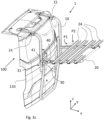
- Fig. 3c depicts a perspective view of the load carrier 1 when the load carrier platform 20 is provided in the use position.
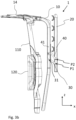
- Fig. 3b depicts a side view of the load carrier 1 when the load carrier platform 20 is provided in the stow away position.
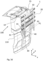
- Fig. 3d depicts a perspective view of the load carrier 1 when the load carrier platform 20 is provided in the stow away position.
- a portion of a vehicle 100 is also shown, indicating how the load carrier 1 can be attached to a rearward facing door or tailgate 110 of the vehicle 100.
- the upper attachment members 14, 15 for attaching the load carrier 1 to the vehicle 100 are here similar to the ones described with respect to fig. 2 .
- the lower attachment members are for simplicity not shown in this embodiment.
- the load carrier 1 is adapted so that the load carrier platform 20 can be pivoted about a pivot axis P1 between the stow away position the use position. Accordingly, the load carrier platform 20 is connected to the attachment arrangement 10 via the pivot axis P1.
- the pivot axis P1 is also here provided offset from the attachment arrangement 10 in the rearward direction x.
- the load carrier 1 in figs. 3a-d comprises at least one connection member 30 which is attached to the attachment arrangement 10 at an attachment position 31 on the attachment arrangement 10.
- the load carrier 1 as shown in figs. 3a-d is adapted so that the pivot axis P1 is provided above the attachment position 31 when the load carrier platform 20 is in the use position, as seen in the height extension z of the load carrier 1.
- the load carrier 1 as shown in figs. 3a-d is adapted so that the pivot axis P1 is translatable with respect to the attachment arrangement 10.
- the load carrier 1 may as shown be adapted so that the pivot axis P1 is moved downward with respect to the attachment arrangement 10 when the load carrier platform 20 is pivoted from the use position to the stow away position and so that the pivot axis P1 is moved upward with respect to the attachment arrangement 10 when the load carrier platform 20 is pivoted from the stow away position to the use position, as seen in the height extension z of the load carrier 1.
- the load carrier 1 may be adapted so that the load carrier platform 20 can be pivoted about an auxiliary pivot axis P2 between the stow away position and the use position.
- the auxiliary pivot axis P2 is in the shown embodiment provided outside of the pivot axis P1, as seen when the load carrier platform 20 is in the use position, and above the pivot axis P1, as seen when the load carrier platform 20 is in the stow away position.
- the load carrier 1 comprises at least one auxiliary connection member 40 which mechanically connects the load carrier platform 20 to the attachment arrangement 10.
- the at least one auxiliary connection member 40 is an auxiliary arm member 40.
- the arm member 30 and the auxiliary arm member 40 may in this embodiment be denoted linkage arm members.
- the arm member 30 and the auxiliary arm member 40 are pivotally connected to the load carrier platform 20 and also pivotally connected to the attachment arrangement 10. Accordingly, the attachment position 31 is a pivotable connection.
- the auxiliary connection member 40 is in a similar manner connected to the attachment arrangement 10 at an attachment position 41. As such, the attachment position 41 is also a pivotable connection.
- the auxiliary pivot axis P2 is associated with the at least one auxiliary connection member 40.
- the auxiliary pivot axis P2 extends through the at least one auxiliary connection member 40.
- the auxiliary pivot axis extends in the width extension y of the load carrier 1.
- the attachment interfaces of the load carrier 1 in figs. 3a-d are also mirrored in the width extension y, like the load carrier 1 shown in fig. 2 .
- the linkage arms 30, 40 are not shown on the distant side of the load carrier 1.
- the load carrier 1 according to the invention may comprise two separate attachment interfaces between the attachment arrangement 10 and the load carrier platform 20, one on each side of the load carrier 1, as seen in the width extension y.
- Figs. 3a-b also show taillights 120 of the vehicle 100.
- the taillights can be more visible.
- the load carrier platform 20 will be provided at least partly above the taillights 120 when it is in the use position. Thereby, bicycles, or any other load, on the load carrier platform 20 will not occlude the taillights 120 during driving.
- Figs. 4a-b depict schematic views from the side of a load carrier 1 according to an example embodiment of the present invention. As in the above, like reference characters refer to the same, or similar, elements.
- Fig. 4s shows a smallest distance x2, as seen in the length extension x of the load carrier 1, and at least when the load carrier platform 20 is in the use position, between the pivot axis P1 and the lower attachment member 14.
- the distance x2 may be 15 to 40 cm, such as 15 to 35 cm, for example 20 to 35 cm or 25 to 35 cm.
- a smallest distance x3, as seen in the length extension x of the load carrier 1, and at least when the load carrier platform 20 is in the use position, between the pivot axis P1 and the rearward facing door or tailgate 110 of the vehicle may be 15 to 40 cm, such as 15 to 35 cm, for example 20 to 35 cm or 25 to 35 cm.
- the at least one connection member 30 may be rigidly fixed to the attachment arrangement 10 or, alternatively, it may be pivotally connected to the attachment arrangement 10 at the attachment position 31.
- an additional gain corresponding at least partly to a length L2 of the at least one connection member 30 can be achieved when the load carrier platform 20 is folded to the stow away position.
- fig. 4b shows such an embodiment and also the situation when the load carrier platform 20 is folded to the stow away position, i.e. when it is extending upward in the height extension z.
- the pivot axis P1 can due to the additional pivoting movement at the attachment position 31 be moved downward with respect to the attachment arrangement 10, thereby reducing the height position of the outermost portion of the load carrier platform 20.
- Fig. 5 depicts a schematic view from the side of a load carrier 1 according to another example embodiment of the present invention.
- the load carrier 1 is adapted so that the pivot axis P1 is provided below the load carrier platform 20 and/or below at least one load receiving member (not shown) of the load carrier platform 20 when the load carrier platform 20 is in the use position, as seen in the height extension z of the load carrier 1.
- the pivot axis P1 may be provided below the load carrier platform 20 so that a distance z1 between the pivot axis P1 and a center line x0 of the load carrier platform 20 is 25-75 millimeters (mm), such as 25-50 mm or 30-40 mm.
- the center line x0 is here defined as a centerline of a frame element forming the load carrier platform 20, such as a tube formed element.
- Figs. 6a-b show schematically a prior art load carrier when it is first in a use position and then in a stow away position.
- the pivot axis is provided on the attachment arrangement, there is a significant risk that the load carrier platform will extend above the vehicle roof when load carrier platform is in the stow away position.
Landscapes
- Engineering & Computer Science (AREA)
- Mechanical Engineering (AREA)
- Fittings On The Vehicle Exterior For Carrying Loads, And Devices For Holding Or Mounting Articles (AREA)
Abstract
Description
- The present disclosure relates to a load carrier for a vehicle, wherein the load carrier comprises an attachment arrangement for attaching the load carrier at a rearward facing door or tailgate of the vehicle.
- Load carriers for vehicles, such as load carriers for carrying bicycles or any other load, may be attached to a vehicle at different sides of the vehicle. For example, it is well-known to provide bicycle carriers which are attachable on top of the vehicle above the vehicle roof, via e.g. vehicle roof racks. It is also known to attach load carriers at vehicle rearward sides, such that the loads can be stored behind the vehicles.
- Load carriers for vehicle rearward sides may be attached directly to the vehicle via an attachment arrangement of the load carrier which comprises one or more attachment members. For certain types of vehicles - including but not limited to minibuses, vans, station wagons and SUV's - it is for example known to attach load carriers to the rearward facing door or tailgate.
- An attachment arrangement for such a load carrier may typically comprise two upper attachment members for attaching the load carrier to the vehicle and for suspending the load carrier thereto via an upper portion of the vehicle at the rearward facing door or tailgate. The attachment arrangement may also comprise at least one lower attachment member for attaching the load carrier to a lower portion of the vehicle at the rearward facing door or tailgate. The lower portion of the vehicle is provided below the at least one upper portion, as seen in a vertical direction of the vehicle, also corresponding to a vertical direction, or height direction, of the attachment arrangement and of the load carrier when attached to the vehicle.
- Typically, the upper attachment members suspend the load carrier and thereby prevent it from falling off due to gravitational forces. They also typically prevent the attachment arrangement and/or the load carrier from moving outward from the vehicle in its rearward direction when attached thereto. The at least one lower attachment member, on the other hand, may prevent the attachment arrangement and/or the load carrier from moving upward in the vertical direction. Thereby, the load carrier is prevented from releasing due to upwardly acting forces generated when the vehicle e.g. drives over a bump or the like. This may be accomplished in that the at least one lower attachment member engages with a downwardly facing edge of the rearwardly facing door or tailgate. Thus, the downwardly facing edge prevents the at least one lower attachment member from moving upwards when an upwardly directed force is acting on the load carrier. The at least one lower attachment member is typically also, or alternatively, designed to prevent the attachment arrangement and/or the load carrier from moving outwards from the vehicle in its rearward direction when attached thereto.
- The load carrier may also comprise a load carrier platform for carrying a load. The load may for example be one or more bicycles, even though also other types of loads may be accommodated on the load carrier platform.
- Typically, the load carrier is adapted so that the load carrier platform can be pivoted between a stow away position and a use position for carrying the load. In the stow away position, the load carrier platform is folded in towards the attachment arrangement. Further, in the use position, the load carrier platform is folded out with respect to the attachment arrangement in a rearward direction of the load carrier, corresponding to a rearward direction of the vehicle when the load carrier is mounted, i.e. attached, thereto.
- Even though the above-mentioned load carriers provide a reliable and robust attachment to the vehicle and also enables the loads to be carried in an efficient manner behind the vehicle, it has been realized that there is still a need to provide further improved and/or alternative load carriers. For example, it has been realized that the folding mechanism is not always suitable for all types of vehicles, and also not for all types of rearward facing doors and tailgates.
- In view of the above, an object of the present invention is to provide an improved load carrier which alleviates at least one of the drawbacks of the prior art. For example, an object of the present invention is to provide a load carrier with an improved folding mechanism, or at least to provide a load carrier which is a suitable alternative to known load carriers.
- The object is achieved by the subject-matter of
independent claim 1. Advantageous embodiments may be found in the dependent claims and in the accompanying description and drawings. - Thus, there is provided a load carrier for a vehicle, comprising,
- an attachment arrangement for attaching the load carrier at a rearward facing door or tailgate of the vehicle,
- a load carrier platform for carrying a load, such as one or more bicycles.
- The load carrier is adapted so that the load carrier platform can be pivoted about a pivot axis between a stow away position and a use position for carrying the load, wherein, in the stow away position the load carrier platform is folded in towards the attachment arrangement, and, in the use position the load carrier platform is folded out with respect to the attachment arrangement in a rearward direction of the load carrier.
- Furthermore, the pivot axis is provided offset from the attachment arrangement in the rearward direction.
- By offset in the rearward direction from the attachment arrangement is herein meant that the pivot axis is provided further behind in the rearward direction with respect to the attachment arrangement. The rearward direction of the load carrier corresponds to a rearward direction of the vehicle when the load carrier is attached thereto.
- The load carrier extends in a length extension, a height extension and a width extension. The rearward direction extends in the length extension. Furthermore, the height extension of the load carrier is substantially aligned with a height extension of the vehicle when the load carrier is attached thereto. In a similar manner, the width extension of the load carrier is substantially aligned with a width extension of the vehicle when the load carrier is attached thereto. The length, height and width extensions preferably correspond to a Cartesian coordinate system, i.e. the different extensions are perpendicular to each other.
- Preferably, the pivot axis extends in the width extension of the load carrier. The width extension typically corresponds to a horizontal extension when the load carrier is attached to a vehicle which is provided on a flat horizontally extending surface.
- By the provision of a load carrier as disclosed herein, an improved folding mechanism of the load carrier is achieved. For example, it has been realized that the improved folding mechanism is especially useful for certain types of vehicles, when also using a load carrier platform having the same, or similar, size as known load carriers.
- By the improved folding mechanism, the height of the load carrier when the load carrier platform is in the stow away position can be reduced. In particular, the load carrier platform may not extend above the roof of the vehicle when the load carrier platform is in the stow away position. Also, the load carrier platform can still be large enough to carry large, bulky, loads. As such, a compact load carrier is achieved which also is capable of carrying the same amount of loads as previous load carriers.
- The improved folding mechanism is achieved in that the pivot axis whereabout the load carrier platform is pivoted is provided offset, i.e. further away, from the attachment arrangement in the rearward direction. This results in that a length from the pivot axis to an outermost portion of the load carrier platform will be shorter compared to if the pivot axis would be provided on the attachment arrangement. As such, when the load carrier platform is provided in the stow away position, and substantially extends upward in the height extension of the load carrier, the load carrier platform will not extend upward in the height extension as far as if the pivot axis would be provided on the attachment arrangement instead. Thereby, it can be avoided that the load carrier platform extends above the roof of the vehicle whilst still enabling a large load carrier platform.
- A further advantage of this configuration is that it will enable the attachment arrangement to be made more compact, as seen in the height extension of the load carrier. Since the load carrier platform will not extend as much upward in the height extension when in the stow away position, the load carrier platform may be mounted to the attachment arrangement at a higher position compared to known load carriers. This results in that the attachment arrangement can be made more compact, e.g. allowing its lower attachment members to be provided higher up, as seen in the height extension. It has been realized that this design freedom is especially advantageous for certain types of vehicles. For example, some vehicles may have taillights which are provided relatively high up at the rearward side of the vehicle. By the provision of the load carrier as disclosed herein, these taillights may not be occluded by the load carrier since the attachment arrangement can be made more compact. For example, the load carrier platform, and the lower attachment member(s) of the attachment arrangement, can be provided higher up at the vehicle's rearward side, enabling taillights to be more visible when the load carrier is mounted to the vehicle.
- The load carrier platform may be configured to carry loads such as one or more bicycles. For example, the load carrier may be configured to carry two, three, four or more bicycles. The load carrier may be configured so that longitudinal extensions of the bicycles substantially coincide with the width extension of the load carrier when the load carrier carries the bicycles.
- Optionally, the attachment arrangement may comprise at least one upper attachment member for attaching the load carrier to an upper portion of the vehicle at the rearward facing door or tailgate. For example, the at least one upper attachment member may be configured to be attached to a vehicle rear spoiler of the vehicle, i.e. the upper portion of the vehicle may be a vehicle rear spoiler. Still optionally, the attachment arrangement may comprise at least one lower attachment member for attaching the load carrier to a lower portion of the vehicle at the rearward facing door or tailgate. The lower portion is thus provided below the upper portion, such as below the vehicle rear spoiler. Accordingly, the at least one upper attachment member is preferably provided above the at least one lower attachment member, as seen along the height extension of the attachment arrangement, which corresponds to the height extension of the vehicle when the attachment arrangement, and thus the load carrier, is attached thereto.
- Optionally, the load carrier may be adapted so that a portion of the load carrier platform is provided and extends between the attachment arrangement and the pivot axis when the load carrier platform is in the use position. Thereby, the load carrier platform will be longer than the length between the pivot axis and the outermost portion of the load carrier platform. Consequently, it enables more load to be carried by the load carrier platform when it is in the use position, whilst still avoiding that the load carrier platform extends above the roof of the vehicle when in the stow away position.
- Optionally, the load carrier may further comprise at least one connection member, such as at least one arm member, which mechanically connects the load carrier platform to the attachment arrangement, wherein the pivot axis is associated with the at least one connection member, such as the pivot axis extends through the at least one connection member. By using at least one connection member, such as at least one arm member, a rigid and robust connection between the load carrier platform and the attachment arrangement can be achieved, while at the same time the pivot axis is offset from the attachment arrangement in the rearward direction. The at least one connection member may be a separate element with respect to the attachment arrangement, or alternatively the at least one connection member may be an integral part of the attachment arrangement. For example, the at least one connection member may be attached to the attachment arrangement by a fixation means, such as a screw or bolt, a weld etc.
- Optionally, the at least one connection member may comprise at least two connection member portions, as seen in a plane defined by the height extension and the rearward direction of the load carrier, wherein one connection member portion extends downward in the height extension, allowing the load carrier platform to be provided further down with respect to the attachment arrangement, and another connection member portion extends in the rearward direction, allowing the pivot axis to be offset from the attachment arrangement in the rearward direction. Still optionally, the at least one connection member may be L-formed. An L-formed connection member implies that the connection member comprises at least two connection member portions which extends so that they together form an L-shape. Thereby, the load carrier platform can be provided at a more suitable position with respect to the attachment arrangement, implying a more compact load carrier configuration, taillights more visible etc.
- Optionally, the at least one connection member may be attached to the attachment arrangement at an attachment position on the attachment arrangement, wherein the load carrier is adapted so that the pivot axis is provided below the attachment position, at least when the load carrier platform is in the stow away position, as seen in the height extension of the load carrier. Still optionally, the load carrier may further be adapted so that the pivot axis is provided below the attachment position also when the load carrier platform is in the use position.
- Optionally, the load carrier platform may comprise one or more load receiving members for receiving a load, wherein the load carrier is adapted so that at least one of the one or more load receiving members is at least partly provided between the attachment position on the attachment arrangement and the pivot axis when the load carrier platform is in the stow away position, as seen in the height extension of the load carrier. This configuration may imply that more load can be loaded onto the load carrier platform. For example, this configuration may allow more bicycles to be carried on the load carrying platform while still the load carrier platform can be prevented from extending above the roof of the vehicle in the stow away position. By way of example, the one or more load receiving members may be members which are adapted to carry and receive bicycles, such as bicycle wheels. For example, a load receiving member may be a wheel tray for receiving a wheel.
- Optionally, the at least one connection member may be rigidly fixed to the attachment arrangement. By rigidly fixed is in this context meant that the at least one connection member is non-pivotally fixed to the attachment arrangement. For example, the at least one connection member may be rigidly fixed to the attachment arrangement by at least two offset fixation means, such as screws or bolts, or welds. This implies a rigid and robust connection to the attachment arrangement.
- Optionally, the load carrier may be adapted so that the pivot axis is provided above the attachment position when the load carrier platform is in the use position, as seen in the height extension of the load carrier. This configuration enables the load carrier platform to be provided higher up at the rearward side of the vehicle in the use position, implying that the taillights may be more visible.
- Optionally, the load carrier may be adapted so that the pivot axis is fixed with respect to the attachment arrangement. This configuration implies a more robust and rigid load carrier.
- Optionally, the load carrier may be adapted so that the pivot axis is translatable with respect to the attachment arrangement. This configuration implies a more versatile configuration, allowing the load carrier platform to not only be pivotable about the pivot axis, but also to be translatable with respect to the attachment arrangement. Thereby, by way of example, the load carrier platform may be allowed to be provided higher up at the rearward side of the vehicle when in the use position, and further down when in the stow away position.
- Still optionally, the load carrier may further be adapted so that the pivot axis is moved downward with respect to the attachment arrangement when the load carrier platform is pivoted from the use position to the stow away position and so that the pivot axis is moved upward with respect to the attachment arrangement when the load carrier platform is pivoted from the stow away position to the use position, as seen in the height extension of the load carrier.
- Optionally, the load carrier may be adapted so that the load carrier platform can be pivoted about an auxiliary pivot axis between the stow away position and the use position. The auxiliary pivot axis is preferably extending in the same direction as the aforementioned pivot axis. This configuration implies a more versatile configuration, i.e. it enables for more freedom of movement of the load carrier platform with respect to the attachment arrangement.
- Optionally, the load carrier may further comprise at least one auxiliary connection member, such as at least one auxiliary arm member, which mechanically connects the load carrier platform to the attachment arrangement. Still optionally, the auxiliary pivot axis may be associated with the at least one auxiliary connection member, such as the auxiliary pivot axis extending through the at least one auxiliary connection member. This configuration implies a more versatile load carrier. For example, by having an auxiliary connection member, in addition to the aforementioned connection member, a larger movement freedom of the load carrier platform with respect to the attachment arrangement can be achieved. This in turn may allow the load carrier platform to be more suitably located in the stow away position and in the use position. For example, this may allow the load carrier platform to be provided further down in the stow away position and higher up in the use position, compared to a load carrier platform having less freedom of movement.
- Optionally, the load carrier may be adapted so that the pivot axis is provided below the load carrier platform and/or below at least one load receiving member of the load carrier platform when the load carrier platform is in the use position, as seen in the height extension of the load carrier. This configuration implies that the load carrier platform can be provided higher up at the rearward side of the vehicle when in the use position. It further implies that the load carrier platform may be provided closer to the attachment arrangement when in the stow away position, i.e. it may provide a more compact load carrier when the load carrier platform is in the stow away position.
- Optionally, when the attachment arrangement comprises at least one lower attachment member for attaching the load carrier to a lower portion of the vehicle at the rearward facing door or tailgate, the pivot axis and/or the auxiliary pivot axis may be provided 0-20 centimeters (cm) from the at least one lower attachment member, as measured in the height extension of the load carrier. For example, the pivot axis and/or the auxiliary pivot axis may be provided 0-15, 0-10 or 0-5 cm from the at least one lower attachment member, as measured in the height extension of the load carrier. The measurement corresponds to a smallest distance between the pivot axis and the at least one lower attachment member and/or to a smallest distance between the auxiliary pivot axis and the at least one lower attachment member, as seen in the height extension of the load carrier. Purely by way of example, the pivot axis and/or the auxiliary pivot axis may, at least in one load carrier platform position, be provided at the same height level as the height level of the at least one lower attachment arrangement. Additionally, or alternatively, the pivot axis and/or the auxiliary pivot axis may be provided above the at least one lower attachment member, as seen in the height extension, and at least when the load carrier platform is in the use position.
- With reference to the appended drawings, below follows a more detailed description of embodiments of the invention cited as examples.
- In the drawings:
-
Figs. 1a-b show side views of a load carrier according to an example embodiment of the present invention, -
Fig. 2 shows a perspective view of a load carrier according to an example embodiment of the present invention, -
Figs. 3a-b show side views of a load carrier according to an example embodiment of the present invention, -
Figs. 3c-d show perspective views of the load carrier as shown infigs. 3a-b , -
Figs. 4a-b show schematic side views of a load carrier according to example embodiments of the present invention, -
Fig. 5 shows a schematic side view of a load carrier according to another example embodiment of the present invention, and -
Figs. 6a-b show schematic views from the side of a prior art load carrier. - The drawings show diagrammatic exemplifying embodiments of the present invention and are thus not necessarily drawn to scale. It shall be understood that the embodiments shown and described are exemplifying and that the invention is not limited to these embodiments. It shall also be noted that some details in the drawings may be exaggerated in order to better describe and illustrate the invention. Like reference characters refer to like elements throughout the description, unless expressed otherwise.
-
Figs. 1a and1b show side views of aload carrier 1 for a vehicle according to an example embodiment of the present invention. Theload carrier 1 extends in a height extension z and length extension x. The height extension z corresponds to a height extension of a vehicle (not shown) when theload carrier 1 is attached to the vehicle. The length extension x corresponds to the length extension of the vehicle when theload carrier 1 is attached thereto. In the shown embodiment, the length extension x points in a rearward direction, corresponding to a rearward direction of theload carrier 1 and of vehicle when theload carrier 1 is attached thereto. - The
load carrier 1 comprises: - an
attachment arrangement 10 for attaching theload carrier 1 at a rearward facing door or tailgate of the vehicle, and - a
load carrier platform 20 for carrying a load, such as one or more bicycles. - The
load carrier 1 is adapted so that theload carrier platform 20 can be pivoted about a pivot axis P1 between a stow away position as shown infig. 1a and a use position for carrying the load as shown infig. 1b . Accordingly, theload carrier platform 20 is connected to theattachment arrangement 10 via the pivot axis P1. - In the stow away position the
load carrier platform 20 is folded in towards theattachment arrangement 10, and, in the use position theload carrier platform 20 is folded out with respect to theattachment arrangement 10 in the rearward direction x of theload carrier 1. - Furthermore, the pivot axis P1 is provided offset from the
attachment arrangement 10 in the rearward direction x. According to example embodiments, a smallest distance x1 between the pivot axis P1 and theattachment arrangement 10, as seen in the length extension x of theload carrier 1, and at least when theload carrier platform 20 is in the use position, is 3 to 30 cm, such as 5 to 30 cm, for example 5-20 cm or 5-10 cm. - As shown in e.g.
fig 1b , theload carrier 1 may be adapted so that aportion 22 of theload carrier platform 20 is provided and extends between theattachment arrangement 10 and the pivot axis P1 when theload carrier platform 20 is in the use position. This allows load to be provided also in this area between the pivot axis P1 and theattachment arrangement 10. - As further shown, when the
load carrier platform 20 is in the use position, theportion 22 of theload carrier platform 20 may be provided in asupport portion 12 associated with theattachment member 10. Thesupport portion 12 provides support to theload carrier platform 10 so that downwardly directed forces outside the pivot axis P1 in the rearward direction x are accommodated by thesupport portion 12. - As further shown in e.g.
figs. 1a-b , theload carrier 1 may further comprise at least oneconnection member 30 which mechanically connects theload carrier platform 20 to theattachment arrangement 10, wherein the pivot axis P1 is associated with the at least oneconnection member 30. In the shown example embodiment, the pivot axis P1 extends through the at least oneconnection member 30. Furthermore, as shown, the at least oneconnection member 30 may be configured as anarm member 30. - As shown, the at least one
connection member 30 may comprise at least twoconnection member portions load carrier 1. Oneconnection member portion 32 extends downward in the height extension z, allowing theload carrier platform 20 to be provided further down with respect to theattachment arrangement 10, and anotherconnection member portion 33 extends in the rearward direction x, thereby allowing the pivot axis P1 to be offset from theattachment arrangement 10 in the rearward direction x. In the example shown infigs. 1a-b , the at least oneconnection member 30 is L-formed. - The at least one
connection member 30 is in the shown embodiment attached to theattachment arrangement 10 at anattachment position 31 on theattachment arrangement 10. In the shown embodiment, there are two attachment positions, 31, 34, which are offset from each other. Theload carrier 1 is adapted so that the pivot axis P1 is provided below the attachment positions 31, 34 when theload carrier platform 20 is in the stow away position and also when it is in the use position, as seen in the height extension z of theload carrier 1. In the shown embodiment, the attachment of the at least oneconnection member 30 to theattachment member 10 is realized by screws or bolts. - As further shown in
figs. 1a-b , theload carrier platform 20 may comprise one or moreload receiving members 24 for receiving a load. In the shown embodiment, theload receiving members 24 are in the form of wheel trays for receiving bicycle wheels (not shown). Theload carrier 1 is adapted so that at least one of the one or moreload receiving members 24 is at least partly provided between theattachment position 31 on theattachment arrangement 10 and the pivot axis P1 when theload carrier platform 20 is in the stow away position, as seen in the height extension z of theload carrier 1. In the shown embodiment, the at least one of the one or moreload receiving members 24 is also at least partly provided between theattachment position 34 on theattachment arrangement 10 and the pivot axis P1 when theload carrier platform 20 is in the stow away position. - As further shown in e.g.
figs. 1a-b , the at least oneconnection member 30 is rigidly fixed to theattachment arrangement 10. In other words, the at least oneconnection member 30 cannot be pivoted with respect to theattachment arrangement 10. However, in an alternative embodiment, as shown infigs. 3a-d , the at least one connection member can be pivoted with respect to the attachment arrangement. - The
load carrier 1 may as further shown infigs. 1a-b be adapted so that the pivot axis P1 is fixed with respect to theattachment arrangement 10. Accordingly, the pivot axis P1 may always be provided at a constant distance from theattachment arrangement 10. - Furthermore, as shown in
figs. 1a-b , theload carrier 1 may also be adapted so that the pivot axis P1 is provided below theload carrier platform 20 and/or below at least oneload receiving member 24 of theload carrier platform 20 when theload carrier platform 20 is in the use position, as seen in the height extension z of theload carrier 1. - By the
load carrier 1 configuration, an improved folding mechanism is achieved. This is achieved in that the pivot axis P1 whereabout theload carrier platform 20 is pivoted is provided offset, or further away, from theattachment arrangement 10 in the rearward direction x. This results in that a length L1 from the pivot axis to an outermost portion of theload carrier platform 20 will be shorter compared to if the pivot axis P1 would be provided directly on theattachment arrangement 10. As a result, when theload carrier platform 20 is provided in the stow away position, and substantially extends upward in the height extension z of theload carrier 1, theload carrier platform 20 may not extend upward in the height extension z as far as if the pivot axis would be provided on theattachment arrangement 10. Thereby, it can be avoided that theload carrier platform 20 extends above the roof of the vehicle whilst still enabling a largeload carrier platform 20. - The
load carrier 1 may further comprise a holdingmember 26 for holding and keeping theload carrier platform 20 in the stow away position. For example, as shown, the holdingmember 26 may be adapted to be releasably attached to theattachment arrangement 10 when theload carrier platform 20 is in the stow away position. In the shown embodiment, the holdingmember 26 is non-removably attached to theload carrier platform 20. Other configurations are of course also possible, such as an opposite configuration where the holding member is non-removably attached to theattachment arrangement 10 and removably attachable to theload carrier platform 20. -
Fig. 2 depicts a perspective view of theload carrier 1 as shown infigs. 1a-b . As shown, theload carrier platform 20 may extend between twoconnection members 30 as mentioned in the above, wherein theconnection members 30 are offset with respect to each other in the width extension y of theload carrier 1. As shown, and according to an example embodiment, the attachment configuration between theload carrier platform 20 and theattachment arrangement 10 may be mirrored in the width extension y so that it forms two equal, or similar, attachment interfaces between theload carrier platform 20 and theattachment arrangement 10. The attachment interfaces are thus separated from each other in the width extension y. - The
load carrier 1 may as shown be formed by a frame structure. As such, theattachment arrangement 10 may be formed by a frame structure. In a similar manner, theload carrier platform 20 may also be formed by a frame structure. For example, the frame structures may be made of aluminum and/or any other rigid material for carrying a load. For example, the frame structures may comprise tube formed profiles, such as tube formed aluminum profiles. - The
attachment arrangement 10 preferably comprises a first and a secondupper attachment member load carrier 1 to an upper portion of the vehicle at the rearward facing door or tailgate. In the shown example, the first and secondupper attachment members upper attachment members load carrier 1. - Furthermore, in the shown embodiment, the
attachment arrangement 10 comprises a first and a secondlower attachment member load carrier 1 to a lower portion of the vehicle at the rearward facing door or tailgate. For example, the first and secondlower attachment members lower attachment members upper attachment members - As shown in
fig 2 , the pivot axis P1 may be provided close to the first and secondlower attachment members load carrier 1. For example, the pivot axis P1 may be provided 0-20 centimeters (cm) from the first and secondlower attachment members load carrier 1. The measurement corresponds to a smallest distance between the pivot axis P1 and the first and secondlower attachment members load carrier 1. - The
load carrier 1 may as shown infig. 2 further comprise one or more load securingarm members 50 for securing the load to theload carrier 1. In the shown embodiment, the load securingarm members 50 are configured to secure bicycles (not shown) to theload carrier 1, by gripping around bicycle frames. Accordingly, each load securing arm member comprises a grippingmember 52 for gripping a bicycle frame. The grippingmembers 52 are in the shown embodiment gripping claws. The load securingarm members 50 are attached to theattachment arrangement 10 and can be pivoted between a use position and a stow away position. In the stow away position, the load securingarm members 50 are substantially extending in the height extension z, such as extending downward, and in the use position, the load securingarm members 50 are as shown extending in the rearward direction x. - The
load carriers 1 as shown in the disclosed embodiments are all configured to carry bicycles. Theload carriers 1 are as shown configured to carry the bicycles so that the longitudinal extensions of the bicycles extend in the width extension y of theload carrier 1. Accordingly, bicycles can be stacked on theload carrier platform 20, one after the other, in the length extension x. - With respect to
figs. 3a-d , anotherload carrier 1 according to the invention will be described. As mentioned in the above, the same reference characters refer to the same, or similar, elements, as described in the above, unless expressed otherwise. -
Fig. 3a depicts a side view of theload carrier 1 when theload carrier platform 20 is provided in the use position.Fig. 3c depicts a perspective view of theload carrier 1 when theload carrier platform 20 is provided in the use position.Fig. 3b depicts a side view of theload carrier 1 when theload carrier platform 20 is provided in the stow away position.Fig. 3d depicts a perspective view of theload carrier 1 when theload carrier platform 20 is provided in the stow away position. Infigs. 3a-d , a portion of avehicle 100 is also shown, indicating how theload carrier 1 can be attached to a rearward facing door or tailgate 110 of thevehicle 100. Theupper attachment members load carrier 1 to thevehicle 100 are here similar to the ones described with respect tofig. 2 . The lower attachment members are for simplicity not shown in this embodiment. - The
load carrier 1 is adapted so that theload carrier platform 20 can be pivoted about a pivot axis P1 between the stow away position the use position. Accordingly, theload carrier platform 20 is connected to theattachment arrangement 10 via the pivot axis P1. - The pivot axis P1 is also here provided offset from the
attachment arrangement 10 in the rearward direction x. - Like the embodiments described with respect to
figs. 1a-2 , theload carrier 1 infigs. 3a-d comprises at least oneconnection member 30 which is attached to theattachment arrangement 10 at anattachment position 31 on theattachment arrangement 10. - However, the
load carrier 1 as shown infigs. 3a-d is adapted so that the pivot axis P1 is provided above theattachment position 31 when theload carrier platform 20 is in the use position, as seen in the height extension z of theload carrier 1. - Still further, differing from the embodiments of
figs. 1a-2 , theload carrier 1 as shown infigs. 3a-d is adapted so that the pivot axis P1 is translatable with respect to theattachment arrangement 10. - The
load carrier 1 may as shown be adapted so that the pivot axis P1 is moved downward with respect to theattachment arrangement 10 when theload carrier platform 20 is pivoted from the use position to the stow away position and so that the pivot axis P1 is moved upward with respect to theattachment arrangement 10 when theload carrier platform 20 is pivoted from the stow away position to the use position, as seen in the height extension z of theload carrier 1. - In addition, as shown, the
load carrier 1 may be adapted so that theload carrier platform 20 can be pivoted about an auxiliary pivot axis P2 between the stow away position and the use position. The auxiliary pivot axis P2 is in the shown embodiment provided outside of the pivot axis P1, as seen when theload carrier platform 20 is in the use position, and above the pivot axis P1, as seen when theload carrier platform 20 is in the stow away position. - In the shown embodiment, the
load carrier 1 comprises at least oneauxiliary connection member 40 which mechanically connects theload carrier platform 20 to theattachment arrangement 10. In the shown embodiment, the at least oneauxiliary connection member 40 is anauxiliary arm member 40. - The
arm member 30 and theauxiliary arm member 40 may in this embodiment be denoted linkage arm members. Thearm member 30 and theauxiliary arm member 40 are pivotally connected to theload carrier platform 20 and also pivotally connected to theattachment arrangement 10. Accordingly, theattachment position 31 is a pivotable connection. Theauxiliary connection member 40 is in a similar manner connected to theattachment arrangement 10 at anattachment position 41. As such, theattachment position 41 is also a pivotable connection. - As shown, the auxiliary pivot axis P2 is associated with the at least one
auxiliary connection member 40. In the shown embodiment, the auxiliary pivot axis P2 extends through the at least oneauxiliary connection member 40. Like the pivot axis P1, the auxiliary pivot axis extends in the width extension y of theload carrier 1. - The attachment interfaces of the
load carrier 1 infigs. 3a-d are also mirrored in the width extension y, like theload carrier 1 shown infig. 2 . For simplicity, thelinkage arms load carrier 1. Accordingly, theload carrier 1 according to the invention may comprise two separate attachment interfaces between theattachment arrangement 10 and theload carrier platform 20, one on each side of theload carrier 1, as seen in the width extension y. -
Figs. 3a-b also showtaillights 120 of thevehicle 100. By the configuration of theload carrier 1, the taillights can be more visible. For example, as shown, theload carrier platform 20 will be provided at least partly above thetaillights 120 when it is in the use position. Thereby, bicycles, or any other load, on theload carrier platform 20 will not occlude thetaillights 120 during driving. -
Figs. 4a-b depict schematic views from the side of aload carrier 1 according to an example embodiment of the present invention. As in the above, like reference characters refer to the same, or similar, elements. - Fig. 4s shows a smallest distance x2, as seen in the length extension x of the
load carrier 1, and at least when theload carrier platform 20 is in the use position, between the pivot axis P1 and thelower attachment member 14. The distance x2 may be 15 to 40 cm, such as 15 to 35 cm, for example 20 to 35 cm or 25 to 35 cm. Additionally, or alternatively, a smallest distance x3, as seen in the length extension x of theload carrier 1, and at least when theload carrier platform 20 is in the use position, between the pivot axis P1 and the rearward facing door or tailgate 110 of the vehicle may be 15 to 40 cm, such as 15 to 35 cm, for example 20 to 35 cm or 25 to 35 cm. - As mentioned in the above, the at least one
connection member 30 may be rigidly fixed to theattachment arrangement 10 or, alternatively, it may be pivotally connected to theattachment arrangement 10 at theattachment position 31. In the event the at least oneconnection member 30 is pivotally connected at theattachment position 31, an additional gain corresponding at least partly to a length L2 of the at least oneconnection member 30 can be achieved when theload carrier platform 20 is folded to the stow away position. More specifically,fig. 4b shows such an embodiment and also the situation when theload carrier platform 20 is folded to the stow away position, i.e. when it is extending upward in the height extension z. The pivot axis P1 can due to the additional pivoting movement at theattachment position 31 be moved downward with respect to theattachment arrangement 10, thereby reducing the height position of the outermost portion of theload carrier platform 20. -
Fig. 5 depicts a schematic view from the side of aload carrier 1 according to another example embodiment of the present invention. As in the above, like reference characters refer to the same, or similar, elements. In this embodiment, theload carrier 1 is adapted so that the pivot axis P1 is provided below theload carrier platform 20 and/or below at least one load receiving member (not shown) of theload carrier platform 20 when theload carrier platform 20 is in the use position, as seen in the height extension z of theload carrier 1. - As shown, the pivot axis P1 may be provided below the
load carrier platform 20 so that a distance z1 between the pivot axis P1 and a center line x0 of theload carrier platform 20 is 25-75 millimeters (mm), such as 25-50 mm or 30-40 mm. The center line x0 is here defined as a centerline of a frame element forming theload carrier platform 20, such as a tube formed element. -
Figs. 6a-b show schematically a prior art load carrier when it is first in a use position and then in a stow away position. As can be seen, when the pivot axis is provided on the attachment arrangement, there is a significant risk that the load carrier platform will extend above the vehicle roof when load carrier platform is in the stow away position. - It is to be understood that the present invention is not limited to the embodiments described above and illustrated in the drawings; rather, the skilled person will recognize that many changes and modifications may be made within the scope of the appended claims.
Claims (15)
- A load carrier (1) for a vehicle (100), comprising,- an attachment arrangement (10) for attaching the load carrier (1) at a rearward facing door or tailgate (110) of the vehicle (100),- a load carrier platform (20) for carrying a load, such as one or more bicycles,wherein the load carrier (1) is adapted so that the load carrier platform (20) can be pivoted about a pivot axis (P1) between a stow away position and a use position for carrying the load, wherein, in the stow away position the load carrier platform (20) is folded in towards the attachment arrangement (10), and, in the use position the load carrier platform (20) is folded out with respect to the attachment arrangement (10) in a rearward direction (x) of the load carrier (1),
characterized in that,
the pivot axis (P1) is provided offset from the attachment arrangement (10) in the rearward direction (x). - The load carrier (1) according to claim 1, wherein the load carrier (1) is adapted so that a portion (22) of the load carrier platform (20) is provided and extends between the attachment arrangement (10) and the pivot axis (P1) when the load carrier platform (20) is in the use position.
- The load carrier (1) according to any one of the preceding claims, further comprising at least one connection member (30), such as at least one arm member (30), which mechanically connects the load carrier platform (20) to the attachment arrangement (10), wherein the pivot axis (P1) is associated with the at least one connection member (30), such as the pivot axis (P1) extends through the at least one connection member (30).
- The load carrier (1) according to claim 3, wherein the at least one connection member (30) comprises at least two connection member portions (32, 33), as seen in a plane defined by a height extension (z) and the rearward direction (x) of the load carrier (1), wherein one connection member portion (32) extends downward in the height extension (z), allowing the load carrier platform (20) to be provided further down with respect to the attachment arrangement (10), and another connection member portion (33) extends in the rearward direction (x), allowing the pivot axis (P1) to be offset from the attachment arrangement (10) in the rearward direction (x).
- The load carrier (1) according to any one of claims 3-4, wherein the at least one connection member (30) is attached to the attachment arrangement (10) at an attachment position (31) on the attachment arrangement (10), wherein the load carrier (1) is adapted so that the pivot axis (P1) is provided below the attachment position (31), at least when the load carrier platform (20) is in the stow away position, as seen in the height extension (z) of the load carrier (1).
- The load carrier (1) according to claim 5, wherein the load carrier platform (20) comprises one or more load receiving members (24) for receiving a load, wherein the load carrier (1) is adapted so that at least one of the one or more load receiving members (24) is at least partly provided between the attachment position (31) on the attachment arrangement (10) and the pivot axis (P1) when the load carrier platform (20) is in the stow away position, as seen in the height extension (z) of the load carrier (1).
- The load carrier (1) according to any one of claims 3-6, wherein the at least one connection member (30) is rigidly fixed to the attachment arrangement (10).
- The load carrier (1) according to any one of claims 5-6, wherein the load carrier (1) is adapted so that the pivot axis (P1) is provided above the attachment position (31) when the load carrier platform (20) is in the use position, as seen in the height extension (z) of the load carrier (1).
- The load carrier (1) according to any one of claims 1-7, wherein the load carrier (1) is adapted so that the pivot axis (P1) is fixed with respect to the attachment arrangement (10).
- The load carrier (1) according to any one of claims 1-8, wherein the load carrier (1) is adapted so that the pivot axis (P1) is translatable with respect to the attachment arrangement (10).
- The load carrier (1) according to claim 10, wherein the load carrier (1) is further adapted so that the pivot axis (P1) is moved downward with respect to the attachment arrangement (10) when the load carrier platform (20) is pivoted from the use position to the stow away position and so that the pivot axis (P1) is moved upward with respect to the attachment arrangement (10) when the load carrier platform (20) is pivoted from the stow away position to the use position, as seen in the height extension (z) of the load carrier (1).
- The load carrier (1) according to any one of claims 10-11, wherein the load carrier (1) is adapted so that the load carrier platform (20) can be pivoted about an auxiliary pivot axis (P2) between the stow away position and the use position.
- The load carrier (1) according to any one of claims 10-12, further comprising at least one auxiliary connection member (40), such as at least one auxiliary arm member (40), which mechanically connects the load carrier platform (20) to the attachment arrangement (10).
- The load carrier (1) according to claims 12 and 13, wherein the auxiliary pivot axis (P2) is associated with the at least one auxiliary connection member (40), such as the auxiliary pivot axis (P2) extends through the at least one auxiliary connection member (40).
- The load carrier (1) according to any one of the preceding claims, wherein the load carrier (1) is adapted so that the pivot axis (P1) is provided below the load carrier platform (20) and/or below at least one load receiving member (24) of the load carrier platform (20) when the load carrier platform (20) is in the use position, as seen in the height extension (z) of the load carrier (1).
Priority Applications (1)
| Application Number | Priority Date | Filing Date | Title |
|---|---|---|---|
| EP21213875.4A EP4194273B1 (en) | 2021-12-10 | 2021-12-10 | A load carrier |
Applications Claiming Priority (1)
| Application Number | Priority Date | Filing Date | Title |
|---|---|---|---|
| EP21213875.4A EP4194273B1 (en) | 2021-12-10 | 2021-12-10 | A load carrier |
Publications (2)
| Publication Number | Publication Date |
|---|---|
| EP4194273A1 true EP4194273A1 (en) | 2023-06-14 |
| EP4194273B1 EP4194273B1 (en) | 2023-10-11 |
Family
ID=78829710
Family Applications (1)
| Application Number | Title | Priority Date | Filing Date |
|---|---|---|---|
| EP21213875.4A Active EP4194273B1 (en) | 2021-12-10 | 2021-12-10 | A load carrier |
Country Status (1)
| Country | Link |
|---|---|
| EP (1) | EP4194273B1 (en) |
Citations (4)
| Publication number | Priority date | Publication date | Assignee | Title |
|---|---|---|---|---|
| US5363996A (en) * | 1993-09-01 | 1994-11-15 | Industri Ab Thule | Bicycle carrier adapted to be mounted on the back of a vehicle |
| US5456564A (en) * | 1994-12-07 | 1995-10-10 | Bianchini; Thomas R. | Winch operated vehicle mounted carrier |
| US6286738B1 (en) * | 1999-12-17 | 2001-09-11 | Yakima Products, Inc. | Bicycle carrier |
| WO2021094713A1 (en) * | 2019-11-13 | 2021-05-20 | Noko Design Technology Manufacture Ltd | Modular carrying system |
-
2021
- 2021-12-10 EP EP21213875.4A patent/EP4194273B1/en active Active
Patent Citations (4)
| Publication number | Priority date | Publication date | Assignee | Title |
|---|---|---|---|---|
| US5363996A (en) * | 1993-09-01 | 1994-11-15 | Industri Ab Thule | Bicycle carrier adapted to be mounted on the back of a vehicle |
| US5456564A (en) * | 1994-12-07 | 1995-10-10 | Bianchini; Thomas R. | Winch operated vehicle mounted carrier |
| US6286738B1 (en) * | 1999-12-17 | 2001-09-11 | Yakima Products, Inc. | Bicycle carrier |
| WO2021094713A1 (en) * | 2019-11-13 | 2021-05-20 | Noko Design Technology Manufacture Ltd | Modular carrying system |
Also Published As
| Publication number | Publication date |
|---|---|
| EP4194273B1 (en) | 2023-10-11 |
Similar Documents
| Publication | Publication Date | Title |
|---|---|---|
| US10737646B2 (en) | Rear impact guard | |
| US8955632B2 (en) | Tubular frame structure for a three-wheeled motor vehicle | |
| US6517134B2 (en) | Vehicle utility rack system providing elevated hauling and working stations | |
| US4088253A (en) | Rack for bicycles | |
| CN102951216B (en) | Automotive rear body structure | |
| US8857689B2 (en) | Articulated ladder rack for semi tractor | |
| US8251426B2 (en) | Collapsible seat construction for a vehicle | |
| WO1993009975A1 (en) | Load carrier | |
| US12459440B2 (en) | Cargo area accessory structure | |
| US20240425122A1 (en) | Pivotable carrier assembly | |
| CN102381363A (en) | Vehicle partition side member structure | |
| US20070181625A1 (en) | Carrier rack system | |
| US20080011795A1 (en) | Bicycle transport rack | |
| US10618572B2 (en) | Vehicle having a load carrying deck and attachment device for the same | |
| US6394524B1 (en) | Pivotable rack apparatus for a pickup truck | |
| EP4194273B1 (en) | A load carrier | |
| US6607346B2 (en) | Spare wheel holding device | |
| WO2015033374A1 (en) | Rear section structure of vehicle body | |
| JP3803542B2 (en) | Rear bumper device in a vehicle with a cargo receiving platform lifting device | |
| US8251268B2 (en) | Carrier for vehicle | |
| EP4029736B1 (en) | A load carrier | |
| US20240227685A1 (en) | Vehicle rack assembly and method of configuring a vehicle rack | |
| JP2567089Y2 (en) | Rear bumper device for vehicles with loading / unloading device | |
| CN223100843U (en) | Top rack for pickup truck and pickup truck | |
| JP2000085636A (en) | Truck bed reinforcement structure |
Legal Events
| Date | Code | Title | Description |
|---|---|---|---|
| STAA | Information on the status of an ep patent application or granted ep patent |
Free format text: STATUS: EXAMINATION IS IN PROGRESS |
|
| PUAI | Public reference made under article 153(3) epc to a published international application that has entered the european phase |
Free format text: ORIGINAL CODE: 0009012 |
|
| 17P | Request for examination filed |
Effective date: 20211210 |
|
| AK | Designated contracting states |
Kind code of ref document: A1 Designated state(s): AL AT BE BG CH CY CZ DE DK EE ES FI FR GB GR HR HU IE IS IT LI LT LU LV MC MK MT NL NO PL PT RO RS SE SI SK SM TR |
|
| GRAP | Despatch of communication of intention to grant a patent |
Free format text: ORIGINAL CODE: EPIDOSNIGR1 |
|
| STAA | Information on the status of an ep patent application or granted ep patent |
Free format text: STATUS: GRANT OF PATENT IS INTENDED |
|
| INTG | Intention to grant announced |
Effective date: 20230623 |
|
| GRAS | Grant fee paid |
Free format text: ORIGINAL CODE: EPIDOSNIGR3 |
|
| GRAA | (expected) grant |
Free format text: ORIGINAL CODE: 0009210 |
|
| STAA | Information on the status of an ep patent application or granted ep patent |
Free format text: STATUS: THE PATENT HAS BEEN GRANTED |
|
| AK | Designated contracting states |
Kind code of ref document: B1 Designated state(s): AL AT BE BG CH CY CZ DE DK EE ES FI FR GB GR HR HU IE IS IT LI LT LU LV MC MK MT NL NO PL PT RO RS SE SI SK SM TR |
|
| REG | Reference to a national code |
Ref country code: GB Ref legal event code: FG4D |
|
| REG | Reference to a national code |
Ref country code: CH Ref legal event code: EP |
|
| REG | Reference to a national code |
Ref country code: DE Ref legal event code: R096 Ref document number: 602021005809 Country of ref document: DE |
|
| REG | Reference to a national code |
Ref country code: IE Ref legal event code: FG4D |
|
| REG | Reference to a national code |
Ref country code: LT Ref legal event code: MG9D |
|
| REG | Reference to a national code |
Ref country code: NL Ref legal event code: MP Effective date: 20231011 |
|
| REG | Reference to a national code |
Ref country code: AT Ref legal event code: MK05 Ref document number: 1619912 Country of ref document: AT Kind code of ref document: T Effective date: 20231011 |
|
| PG25 | Lapsed in a contracting state [announced via postgrant information from national office to epo] |
Ref country code: NL Free format text: LAPSE BECAUSE OF FAILURE TO SUBMIT A TRANSLATION OF THE DESCRIPTION OR TO PAY THE FEE WITHIN THE PRESCRIBED TIME-LIMIT Effective date: 20231011 |
|
| PG25 | Lapsed in a contracting state [announced via postgrant information from national office to epo] |
Ref country code: GR Free format text: LAPSE BECAUSE OF FAILURE TO SUBMIT A TRANSLATION OF THE DESCRIPTION OR TO PAY THE FEE WITHIN THE PRESCRIBED TIME-LIMIT Effective date: 20240112 |
|
| PG25 | Lapsed in a contracting state [announced via postgrant information from national office to epo] |
Ref country code: IS Free format text: LAPSE BECAUSE OF FAILURE TO SUBMIT A TRANSLATION OF THE DESCRIPTION OR TO PAY THE FEE WITHIN THE PRESCRIBED TIME-LIMIT Effective date: 20240211 |
|
| PG25 | Lapsed in a contracting state [announced via postgrant information from national office to epo] |
Ref country code: LT Free format text: LAPSE BECAUSE OF FAILURE TO SUBMIT A TRANSLATION OF THE DESCRIPTION OR TO PAY THE FEE WITHIN THE PRESCRIBED TIME-LIMIT Effective date: 20231011 |
|
| PG25 | Lapsed in a contracting state [announced via postgrant information from national office to epo] |
Ref country code: AT Free format text: LAPSE BECAUSE OF FAILURE TO SUBMIT A TRANSLATION OF THE DESCRIPTION OR TO PAY THE FEE WITHIN THE PRESCRIBED TIME-LIMIT Effective date: 20231011 |
|
| PG25 | Lapsed in a contracting state [announced via postgrant information from national office to epo] |
Ref country code: ES Free format text: LAPSE BECAUSE OF FAILURE TO SUBMIT A TRANSLATION OF THE DESCRIPTION OR TO PAY THE FEE WITHIN THE PRESCRIBED TIME-LIMIT Effective date: 20231011 |
|
| PG25 | Lapsed in a contracting state [announced via postgrant information from national office to epo] |
Ref country code: LT Free format text: LAPSE BECAUSE OF FAILURE TO SUBMIT A TRANSLATION OF THE DESCRIPTION OR TO PAY THE FEE WITHIN THE PRESCRIBED TIME-LIMIT Effective date: 20231011 Ref country code: IS Free format text: LAPSE BECAUSE OF FAILURE TO SUBMIT A TRANSLATION OF THE DESCRIPTION OR TO PAY THE FEE WITHIN THE PRESCRIBED TIME-LIMIT Effective date: 20240211 Ref country code: GR Free format text: LAPSE BECAUSE OF FAILURE TO SUBMIT A TRANSLATION OF THE DESCRIPTION OR TO PAY THE FEE WITHIN THE PRESCRIBED TIME-LIMIT Effective date: 20240112 Ref country code: ES Free format text: LAPSE BECAUSE OF FAILURE TO SUBMIT A TRANSLATION OF THE DESCRIPTION OR TO PAY THE FEE WITHIN THE PRESCRIBED TIME-LIMIT Effective date: 20231011 Ref country code: BG Free format text: LAPSE BECAUSE OF FAILURE TO SUBMIT A TRANSLATION OF THE DESCRIPTION OR TO PAY THE FEE WITHIN THE PRESCRIBED TIME-LIMIT Effective date: 20240111 Ref country code: AT Free format text: LAPSE BECAUSE OF FAILURE TO SUBMIT A TRANSLATION OF THE DESCRIPTION OR TO PAY THE FEE WITHIN THE PRESCRIBED TIME-LIMIT Effective date: 20231011 Ref country code: PT Free format text: LAPSE BECAUSE OF FAILURE TO SUBMIT A TRANSLATION OF THE DESCRIPTION OR TO PAY THE FEE WITHIN THE PRESCRIBED TIME-LIMIT Effective date: 20240212 |
|
| PG25 | Lapsed in a contracting state [announced via postgrant information from national office to epo] |
Ref country code: SE Free format text: LAPSE BECAUSE OF FAILURE TO SUBMIT A TRANSLATION OF THE DESCRIPTION OR TO PAY THE FEE WITHIN THE PRESCRIBED TIME-LIMIT Effective date: 20231011 Ref country code: RS Free format text: LAPSE BECAUSE OF FAILURE TO SUBMIT A TRANSLATION OF THE DESCRIPTION OR TO PAY THE FEE WITHIN THE PRESCRIBED TIME-LIMIT Effective date: 20231011 Ref country code: PL Free format text: LAPSE BECAUSE OF FAILURE TO SUBMIT A TRANSLATION OF THE DESCRIPTION OR TO PAY THE FEE WITHIN THE PRESCRIBED TIME-LIMIT Effective date: 20231011 Ref country code: NO Free format text: LAPSE BECAUSE OF FAILURE TO SUBMIT A TRANSLATION OF THE DESCRIPTION OR TO PAY THE FEE WITHIN THE PRESCRIBED TIME-LIMIT Effective date: 20240111 Ref country code: LV Free format text: LAPSE BECAUSE OF FAILURE TO SUBMIT A TRANSLATION OF THE DESCRIPTION OR TO PAY THE FEE WITHIN THE PRESCRIBED TIME-LIMIT Effective date: 20231011 Ref country code: HR Free format text: LAPSE BECAUSE OF FAILURE TO SUBMIT A TRANSLATION OF THE DESCRIPTION OR TO PAY THE FEE WITHIN THE PRESCRIBED TIME-LIMIT Effective date: 20231011 |
|
| PG25 | Lapsed in a contracting state [announced via postgrant information from national office to epo] |
Ref country code: DK Free format text: LAPSE BECAUSE OF FAILURE TO SUBMIT A TRANSLATION OF THE DESCRIPTION OR TO PAY THE FEE WITHIN THE PRESCRIBED TIME-LIMIT Effective date: 20231011 |
|
| REG | Reference to a national code |
Ref country code: DE Ref legal event code: R097 Ref document number: 602021005809 Country of ref document: DE |
|
| PG25 | Lapsed in a contracting state [announced via postgrant information from national office to epo] |
Ref country code: CZ Free format text: LAPSE BECAUSE OF FAILURE TO SUBMIT A TRANSLATION OF THE DESCRIPTION OR TO PAY THE FEE WITHIN THE PRESCRIBED TIME-LIMIT Effective date: 20231011 |
|
| PG25 | Lapsed in a contracting state [announced via postgrant information from national office to epo] |
Ref country code: SK Free format text: LAPSE BECAUSE OF FAILURE TO SUBMIT A TRANSLATION OF THE DESCRIPTION OR TO PAY THE FEE WITHIN THE PRESCRIBED TIME-LIMIT Effective date: 20231011 |
|
| PG25 | Lapsed in a contracting state [announced via postgrant information from national office to epo] |
Ref country code: SM Free format text: LAPSE BECAUSE OF FAILURE TO SUBMIT A TRANSLATION OF THE DESCRIPTION OR TO PAY THE FEE WITHIN THE PRESCRIBED TIME-LIMIT Effective date: 20231011 Ref country code: SK Free format text: LAPSE BECAUSE OF FAILURE TO SUBMIT A TRANSLATION OF THE DESCRIPTION OR TO PAY THE FEE WITHIN THE PRESCRIBED TIME-LIMIT Effective date: 20231011 Ref country code: RO Free format text: LAPSE BECAUSE OF FAILURE TO SUBMIT A TRANSLATION OF THE DESCRIPTION OR TO PAY THE FEE WITHIN THE PRESCRIBED TIME-LIMIT Effective date: 20231011 Ref country code: EE Free format text: LAPSE BECAUSE OF FAILURE TO SUBMIT A TRANSLATION OF THE DESCRIPTION OR TO PAY THE FEE WITHIN THE PRESCRIBED TIME-LIMIT Effective date: 20231011 Ref country code: DK Free format text: LAPSE BECAUSE OF FAILURE TO SUBMIT A TRANSLATION OF THE DESCRIPTION OR TO PAY THE FEE WITHIN THE PRESCRIBED TIME-LIMIT Effective date: 20231011 Ref country code: CZ Free format text: LAPSE BECAUSE OF FAILURE TO SUBMIT A TRANSLATION OF THE DESCRIPTION OR TO PAY THE FEE WITHIN THE PRESCRIBED TIME-LIMIT Effective date: 20231011 |
|
| PLBE | No opposition filed within time limit |
Free format text: ORIGINAL CODE: 0009261 |
|
| STAA | Information on the status of an ep patent application or granted ep patent |
Free format text: STATUS: NO OPPOSITION FILED WITHIN TIME LIMIT |
|
| PG25 | Lapsed in a contracting state [announced via postgrant information from national office to epo] |
Ref country code: LU Free format text: LAPSE BECAUSE OF NON-PAYMENT OF DUE FEES Effective date: 20231210 |
|
| PG25 | Lapsed in a contracting state [announced via postgrant information from national office to epo] |
Ref country code: MC Free format text: LAPSE BECAUSE OF FAILURE TO SUBMIT A TRANSLATION OF THE DESCRIPTION OR TO PAY THE FEE WITHIN THE PRESCRIBED TIME-LIMIT Effective date: 20231011 |
|
| REG | Reference to a national code |
Ref country code: BE Ref legal event code: MM Effective date: 20231231 |
|
| PG25 | Lapsed in a contracting state [announced via postgrant information from national office to epo] |
Ref country code: MC Free format text: LAPSE BECAUSE OF FAILURE TO SUBMIT A TRANSLATION OF THE DESCRIPTION OR TO PAY THE FEE WITHIN THE PRESCRIBED TIME-LIMIT Effective date: 20231011 Ref country code: LU Free format text: LAPSE BECAUSE OF NON-PAYMENT OF DUE FEES Effective date: 20231210 |
|
| 26N | No opposition filed |
Effective date: 20240712 |
|
| REG | Reference to a national code |
Ref country code: IE Ref legal event code: MM4A |
|
| PG25 | Lapsed in a contracting state [announced via postgrant information from national office to epo] |
Ref country code: IE Free format text: LAPSE BECAUSE OF NON-PAYMENT OF DUE FEES Effective date: 20231210 |
|
| PG25 | Lapsed in a contracting state [announced via postgrant information from national office to epo] |
Ref country code: BE Free format text: LAPSE BECAUSE OF NON-PAYMENT OF DUE FEES Effective date: 20231231 |
|
| PG25 | Lapsed in a contracting state [announced via postgrant information from national office to epo] |
Ref country code: SI Free format text: LAPSE BECAUSE OF FAILURE TO SUBMIT A TRANSLATION OF THE DESCRIPTION OR TO PAY THE FEE WITHIN THE PRESCRIBED TIME-LIMIT Effective date: 20231011 |
|
| PG25 | Lapsed in a contracting state [announced via postgrant information from national office to epo] |
Ref country code: SI Free format text: LAPSE BECAUSE OF FAILURE TO SUBMIT A TRANSLATION OF THE DESCRIPTION OR TO PAY THE FEE WITHIN THE PRESCRIBED TIME-LIMIT Effective date: 20231011 Ref country code: IE Free format text: LAPSE BECAUSE OF NON-PAYMENT OF DUE FEES Effective date: 20231210 Ref country code: BE Free format text: LAPSE BECAUSE OF NON-PAYMENT OF DUE FEES Effective date: 20231231 |
|
| PG25 | Lapsed in a contracting state [announced via postgrant information from national office to epo] |
Ref country code: FI Free format text: LAPSE BECAUSE OF FAILURE TO SUBMIT A TRANSLATION OF THE DESCRIPTION OR TO PAY THE FEE WITHIN THE PRESCRIBED TIME-LIMIT Effective date: 20231011 |
|
| PG25 | Lapsed in a contracting state [announced via postgrant information from national office to epo] |
Ref country code: CY Free format text: LAPSE BECAUSE OF FAILURE TO SUBMIT A TRANSLATION OF THE DESCRIPTION OR TO PAY THE FEE WITHIN THE PRESCRIBED TIME-LIMIT; INVALID AB INITIO Effective date: 20211210 |
|
| REG | Reference to a national code |
Ref country code: CH Ref legal event code: PL |
|
| PG25 | Lapsed in a contracting state [announced via postgrant information from national office to epo] |
Ref country code: CH Free format text: LAPSE BECAUSE OF NON-PAYMENT OF DUE FEES Effective date: 20241231 |
|
| PG25 | Lapsed in a contracting state [announced via postgrant information from national office to epo] |
Ref country code: TR Free format text: LAPSE BECAUSE OF FAILURE TO SUBMIT A TRANSLATION OF THE DESCRIPTION OR TO PAY THE FEE WITHIN THE PRESCRIBED TIME-LIMIT Effective date: 20231011 |
|
| PGFP | Annual fee paid to national office [announced via postgrant information from national office to epo] |
Ref country code: GB Payment date: 20251223 Year of fee payment: 5 |
|
| PGFP | Annual fee paid to national office [announced via postgrant information from national office to epo] |
Ref country code: IT Payment date: 20251218 Year of fee payment: 5 |
|
| PGFP | Annual fee paid to national office [announced via postgrant information from national office to epo] |
Ref country code: FR Payment date: 20251223 Year of fee payment: 5 |
|
| PGFP | Annual fee paid to national office [announced via postgrant information from national office to epo] |
Ref country code: DE Payment date: 20251229 Year of fee payment: 5 |
|
| PG25 | Lapsed in a contracting state [announced via postgrant information from national office to epo] |
Ref country code: HU Free format text: LAPSE BECAUSE OF FAILURE TO SUBMIT A TRANSLATION OF THE DESCRIPTION OR TO PAY THE FEE WITHIN THE PRESCRIBED TIME-LIMIT; INVALID AB INITIO Effective date: 20211210 |