EP4194271A1 - Storage organizing article and system - Google Patents
Storage organizing article and system Download PDFInfo
- Publication number
- EP4194271A1 EP4194271A1 EP22211384.7A EP22211384A EP4194271A1 EP 4194271 A1 EP4194271 A1 EP 4194271A1 EP 22211384 A EP22211384 A EP 22211384A EP 4194271 A1 EP4194271 A1 EP 4194271A1
- Authority
- EP
- European Patent Office
- Prior art keywords
- rows
- retention members
- engagement
- foundation
- sub
- Prior art date
- Legal status (The legal status is an assumption and is not a legal conclusion. Google has not performed a legal analysis and makes no representation as to the accuracy of the status listed.)
- Withdrawn
Links
- 230000014759 maintenance of location Effects 0.000 claims abstract description 111
- 239000000203 mixture Substances 0.000 claims description 6
- 229920001169 thermoplastic Polymers 0.000 claims description 5
- 239000004416 thermosoftening plastic Substances 0.000 claims description 5
- 238000002347 injection Methods 0.000 claims description 4
- 239000007924 injection Substances 0.000 claims description 4
- 238000004519 manufacturing process Methods 0.000 description 13
- 239000004743 Polypropylene Substances 0.000 description 5
- 229920001155 polypropylene Polymers 0.000 description 5
- -1 polypropylene Polymers 0.000 description 4
- 239000004676 acrylonitrile butadiene styrene Substances 0.000 description 2
- RKTYLMNFRDHKIL-UHFFFAOYSA-N copper;5,10,15,20-tetraphenylporphyrin-22,24-diide Chemical compound [Cu+2].C1=CC(C(=C2C=CC([N-]2)=C(C=2C=CC=CC=2)C=2C=CC(N=2)=C(C=2C=CC=CC=2)C2=CC=C3[N-]2)C=2C=CC=CC=2)=NC1=C3C1=CC=CC=C1 RKTYLMNFRDHKIL-UHFFFAOYSA-N 0.000 description 2
- 238000001746 injection moulding Methods 0.000 description 2
- 230000013011 mating Effects 0.000 description 2
- 229920000098 polyolefin Polymers 0.000 description 2
- 239000004800 polyvinyl chloride Substances 0.000 description 2
- 239000004698 Polyethylene Substances 0.000 description 1
- 230000006978 adaptation Effects 0.000 description 1
- 238000000071 blow moulding Methods 0.000 description 1
- 239000013590 bulk material Substances 0.000 description 1
- 238000010276 construction Methods 0.000 description 1
- 230000009969 flowable effect Effects 0.000 description 1
- 239000007788 liquid Substances 0.000 description 1
- 238000000034 method Methods 0.000 description 1
- 238000012986 modification Methods 0.000 description 1
- 230000004048 modification Effects 0.000 description 1
- 238000000465 moulding Methods 0.000 description 1
- 239000002362 mulch Substances 0.000 description 1
- 229920003023 plastic Polymers 0.000 description 1
- 239000004033 plastic Substances 0.000 description 1
- 229920000573 polyethylene Polymers 0.000 description 1
- 238000000926 separation method Methods 0.000 description 1
- 239000002689 soil Substances 0.000 description 1
- 239000007787 solid Substances 0.000 description 1
- 239000004575 stone Substances 0.000 description 1
- 229920002397 thermoplastic olefin Polymers 0.000 description 1
- XLYOFNOQVPJJNP-UHFFFAOYSA-N water Substances O XLYOFNOQVPJJNP-UHFFFAOYSA-N 0.000 description 1
Images


Classifications
-
- B—PERFORMING OPERATIONS; TRANSPORTING
- B60—VEHICLES IN GENERAL
- B60R—VEHICLES, VEHICLE FITTINGS, OR VEHICLE PARTS, NOT OTHERWISE PROVIDED FOR
- B60R7/00—Stowing or holding appliances inside vehicle primarily intended for personal property smaller than suit-cases, e.g. travelling articles, or maps
- B60R7/02—Stowing or holding appliances inside vehicle primarily intended for personal property smaller than suit-cases, e.g. travelling articles, or maps in separate luggage compartment
-
- B—PERFORMING OPERATIONS; TRANSPORTING
- B60—VEHICLES IN GENERAL
- B60N—SEATS SPECIALLY ADAPTED FOR VEHICLES; VEHICLE PASSENGER ACCOMMODATION NOT OTHERWISE PROVIDED FOR
- B60N3/00—Arrangements or adaptations of other passenger fittings, not otherwise provided for
- B60N3/04—Arrangements or adaptations of other passenger fittings, not otherwise provided for of floor mats or carpets
- B60N3/044—Arrangements or adaptations of other passenger fittings, not otherwise provided for of floor mats or carpets of removable mats
-
- B—PERFORMING OPERATIONS; TRANSPORTING
- B60—VEHICLES IN GENERAL
- B60N—SEATS SPECIALLY ADAPTED FOR VEHICLES; VEHICLE PASSENGER ACCOMMODATION NOT OTHERWISE PROVIDED FOR
- B60N3/00—Arrangements or adaptations of other passenger fittings, not otherwise provided for
- B60N3/04—Arrangements or adaptations of other passenger fittings, not otherwise provided for of floor mats or carpets
- B60N3/048—Arrangements or adaptations of other passenger fittings, not otherwise provided for of floor mats or carpets characterised by their structure
-
- B—PERFORMING OPERATIONS; TRANSPORTING
- B60—VEHICLES IN GENERAL
- B60R—VEHICLES, VEHICLE FITTINGS, OR VEHICLE PARTS, NOT OTHERWISE PROVIDED FOR
- B60R7/00—Stowing or holding appliances inside vehicle primarily intended for personal property smaller than suit-cases, e.g. travelling articles, or maps
- B60R7/04—Stowing or holding appliances inside vehicle primarily intended for personal property smaller than suit-cases, e.g. travelling articles, or maps in driver or passenger space, e.g. using racks
-
- F—MECHANICAL ENGINEERING; LIGHTING; HEATING; WEAPONS; BLASTING
- F16—ENGINEERING ELEMENTS AND UNITS; GENERAL MEASURES FOR PRODUCING AND MAINTAINING EFFECTIVE FUNCTIONING OF MACHINES OR INSTALLATIONS; THERMAL INSULATION IN GENERAL
- F16M—FRAMES, CASINGS OR BEDS OF ENGINES, MACHINES OR APPARATUS, NOT SPECIFIC TO ENGINES, MACHINES OR APPARATUS PROVIDED FOR ELSEWHERE; STANDS; SUPPORTS
- F16M11/00—Stands or trestles as supports for apparatus or articles placed thereon ; Stands for scientific apparatus such as gravitational force meters
- F16M11/20—Undercarriages with or without wheels
- F16M11/22—Undercarriages with or without wheels with approximately constant height, e.g. with constant length of column or of legs
Definitions
- the present disclosure relates to a storage organizing article and system, particularly for a motor vehicle such as a land vehicle (e.g. automobile).
- a motor vehicle such as a land vehicle (e.g. automobile).
- a storage organizing article which comprises a foundation comprising a horizontal floor; at least one container having a plurality of engagement footings; wherein the container is releasably connectable to the foundation via the plurality of engagement footings of the container; wherein the horizontal floor has a base wall, a plurality of retention members and a plurality of engagement receptacles; wherein each engagement receptacle of the plurality of engagement receptacles is formed by a sub-grouping of the plurality of retention members, respectively; and wherein, when the foundation and the container are connected, each of the engagement footings of the plurality of engagement footings is respectively disposed in one of the engagement receptacles of the plurality of engagement receptacles and forms a releasable friction fit with the sub-grouping of the plurality of retention members which form the engagement receptacle.
- each of the engagement footings of the plurality of engagement footings comprises a projection, respectively; each retention member of each sub-grouping of the plurality of retention members comprises a projection which projects vertically upward relative to the base wall, respectively; and, when the foundation and the container are connected, each projection of each of the engagement footings is disposed in one of the engagement receptacles, respectively, and forms a releasable friction fit with each of the projections of each sub-grouping which forms the engagement receptacle, respectively.
- the projection of each of the engagement footings is substantially identical.
- the projection of each of the engagement footings is cylindrical in cross-section.
- each retention member of each sub-grouping is substantially identical.
- the projection of each retention member of each sub-grouping is polygonal in cross-section.
- the projection of each retention member of each sub-grouping is square in cross-section.
- each engagement receptacle of the plurality of engagement receptacles formed by a sub-grouping of the plurality of retention members is formed by at least two retention members, respectively.
- each sub-grouping of the plurality of retention members is formed by four retention members, respectively.
- the four retention members of each sub-grouping are substantially equally spaced around a center of each engagement receptacle of the plurality of engagement receptacles, respectively.
- the plurality of retention members are arranged in a plurality of rows; wherein a first set of the plurality of rows are substantially parallel to one another; wherein a second set of the plurality of rows are substantially parallel to one another; and wherein the first set of the plurality of rows and the second set of the plurality of rows are substantially perpendicular to one another.
- the first set of the plurality of rows comprises at least 2 rows, at least 3 rows, at least 4 rows, at least 5 rows, at least 6 rows, at least 7 rows, at least 8 rows, at least 9 rows, at least 10 rows, at least 11 rows, at least 12 rows or at least 13 rows; and the second set of the plurality of rows comprises at least 2 rows, at least 3 rows, at least 4 rows, at least 5 rows, at least 6 rows, at least 7 rows, at least 8 rows, at least 9 rows, at least 10 rows, at least 11 rows, at least 12 rows or at least 13 rows.
- each row of the first set of the plurality of rows comprises at least 2 retention members, at least 3 retention members, at least 4 retention members, at least 5 retention members, at least 6 retention members, at least 7 retention members, at least 8 retention members, at least 9 retention members, at least 10 retention members, at least 11 retention members, at least 12 retention members or at least 13 retention member; and each row of the second set of the plurality of rows comprises at least 2 retention members, at least 3 retention members, at least 4 retention members, at least 5 retention members, at least 6 retention members, at least 7 retention members, at least 8 retention members, at least 9 retention members, at least 10 retention members, at least 11 retention members, at least 12 retention members or at least 13 retention members.
- the base wall is planar.
- the foundation further comprises a perimeter rim which at least partially surrounds the horizontal floor.
- the foundation further comprises a perimeter rim which completely surrounds the horizontal floor.
- the foundation is in a form of a floor mat.
- the foundation is formed of an injection molded thermoplastic composition.
- the container is formed of an injection molded thermoplastic composition.
- the container has a storage volume in a range of 1liter to 100 liters.
- storage organizing article 10 comprises a foundation 20, which may be in a form of a tray or shallow container, particularly for a cargo region of the motor vehicle.
- the cargo region may be a trunk or other storage space typically rearward of a passenger seating region.
- the cargo region may be a trunk (which may be referred to as a frunk) or other storage space typically forward of a passenger seating region. In either instance, the cargo region may or may not be isolated from the passenger region) of a motor vehicle.
- foundation 20 comprises a polygonal (rectangular and more particularly square) horizontal floor 22.
- the foundation 20 may have a non-polygonal shape which follows, for example, the contours of a floor pan or vertical side walls defining a perimeter of the cargo area.
- the one of more sides of the foundation 20 may have one of more recesses and/or protrusions (e.g. see FIG. 12H ) which correspond to protrusions and/or recesses in the cargo area, respectively.
- horizontal floor 22 is at least partially surrounded by a vertically raised perimeter rim 24 (which may be referred to a vertically raised containment wall).
- the, perimeter rim 24 extends continuously around the horizontal floor 22. It should be understood that the perimeter rim 24 is preferably continuous/uninterrupted around that horizontal floor 22 in that the horizonal floor 22 is completely surrounded/enclosed by the perimeter rim 24 on all bordering sides (i.e. 360 degrees).
- the vertically raised perimeter rim 24 may be discontinuous/intermittent around that horizontal floor 22.
- the vertically raised perimeter rim 24 may be discontinuous/intermittent around that horizontal floor 22 at one or more sides of the foundation 20/horizontal floor 22 or may be completely eliminated at one or more sides of the foundation 20/horizontal floor 22.
- Foundation 20 may be particularly configured to contain items stored in a motor vehicle (e.g. groceries, sporting equipment, clothing).
- foundation 20 may be vehicle specific, i.e. dimensioned or otherwise configured to fit a predetermined motor vehicle.
- foundation 20 is formed as a single (monolithic) component, particularly by injection molding a thermoplastic composition comprising, essentially consisting of or consisting of a polyolefin (e.g. polypropylene (PP), acrylonitrile-butadiene-styrene (ABS), polyvinyl chloride (PVC)).
- PP polypropylene
- ABS acrylonitrile-butadiene-styrene
- PVC polyvinyl chloride
- horizontal floor 22 of foundation 20 preferably has a horizontal, planar base wall 28, with a plurality of repeating retention members 30 to retain vertical wall 100 connectable thereto as explained in greater detail below.
- each retention member 30 comprises a raised, spaced apart, vertically upward directed projection 32.
- each projection 32 is polygonal in cross-section, and more particularly a tetragonal (four sides) in cross-section. Even more particularly, each projection 32 is a square (four sides of equal length) in cross-section. As shown, each projection 32 is square with four, vertical, planar side walls 34 of equal length joined by rounded corners 36 (e.g. a fillet). An end of the projection 32 has a horizontal, square, planar end wall 38, also with rounded corners. Each projection 32 has a center 40, which, while not shown, is a center of a square as determined by the intersection of their respective diagonals. As shown, all the projections 32 have a substantially identical geometry, i.e. having an identical geometry within manufacturing tolerances, and adjacent projections 32 are substantially equally spaced from one another, i.e. having an equal spacing within manufacturing tolerance.
- the projections 32 may be arranged in a rectangular grid, which has the projections 32 arranged in a first set of linear rows 1Rn (1R 1 , 1R 2 , etc.) and a second set of linear rows 2Rn (2R 1 , 2R 2 , etc.). As shown, with the first set of rows 1Rn, the rows 1Rn of projections 32 are arranged substantially parallel to one another, i.e. being parallel to each other within manufacturing tolerances. Similarly, with the second set of rows 2Rn, the rows 2Rn of projections 32 are also arranged substantially parallel to one another, i.e. being parallel to each other within manufacturing tolerances.
- first set of rows 1Rn of projections 32 and the second set of rows 2Rn of projections 32 are arranged in two directions/along two axes X and Y substantially perpendicular to one another, i.e. being preferably perpendicular to each other within manufacturing tolerances.
- the first set of the plurality of rows 1R comprises at least 2 rows, at least 3 rows, at least 4 rows, at least 5 rows, at least 6 rows, at least 7 rows, at least 8 rows, at least 9 rows, at least 10 rows, at least 11 rows, at least 12 rows or at least 13 rows.
- the second set of the plurality of rows 2R comprises at least 2 rows, at least 3 rows, at least 4 rows, at least 5 rows, at least 6 rows, at least 7 rows, at least 8 rows, at least 9 rows, at least 10 rows, at least 11 rows, at least 12 rows or at least 13 rows.
- each row of the first set of the plurality of rows 1R comprises at least 2 retention members 30, at least 3 retention members 30, at least 4 retention members 30, at least 5 retention members 30, at least 6 retention members 30, at least 7 retention members 30, at least 8 retention members 30, at least 9 retention members 30, at least 10 retention members 30, at least 11 retention members 30, at least 12 retention members 30 or at least 13 retention members 30.
- Each row of the second set of the plurality of rows 2R comprises at least 2 retention members 30, at least 3 retention members 30, at least 4 retention members 30, at least 5 retention members 30, at least 6 retention members 30, at least 7 retention members 30, at least 8 retention members 30, at least 9 retention members 30, at least 10 retention members 30, at least 11 retention members 30, at least 12 retention members 30 or at least 13 retention members 30.
- a row of the first set of rows 1Rn comprises at least two projections 32
- a row of the second set of rows 2Rn comprises at least two projections 32.
- the smallest grid according to the present disclosure is a two-by-two (i.e. 2x2) grid of projections 32, whereby the first set of rows 1Rn comprises two rows and the second set of rows 2Rn comprises two rows, each with two projections 32.
- first set of rows 1Rn and the second set of rows 2Rn are similarly composed of projections 32
- the distinction between the first set of rows 2Rn and the second set of rows 2Rn delineates the directional arrangement of the sets of rows 1Rn and 2Rn with respect to one another, preferably shown being substantially perpendicular, i.e. being perpendicular to each other within manufacturing tolerances.
- the first set of rows 1Rn may also be referred to extending in an X-direction/axis of the foundation 20/horizontal floor 22 and the second set of rows 2Rn may be referred to as extending in a Y-direction/axis of the foundation 20/horizontal floor 22, which is substantially perpendicular to the first set of rows 1Rn, i.e. being perpendicular to each other within manufacturing tolerances.
- the engagement members 30/projections 32 may be arranged in a sub-grouping 50 of four engagement members 30/projections 32, which is used to engage/retain an engagement footing 140 of one or more vertical wall segments 110 as explained in greater detail below.
- a sub-grouping 50 of four projections 32 are preferably arranged in a two-by-two (i.e. 2x2) sub-grouping, such that the center 40 of each projection 32 of the sub-grouping 50 of four projections 32 is substantially equal distance, i.e. being equal distance to one another within manufacturing tolerance, from a center 40 of two adjacent projections 32 of the sub-grouping 50 of four projections 32.
- the center 40 of each projection 32 of the sub-grouping 50 of four projections 32 provides a corner of an imaginary square 52 linking the sub-grouping 50 of four projections 32.
- a sub-grouping may be understood as a plurality of projections 32, such as at least two projections from the total number of available projections, that engage with the engagement footings 140.
- two opposing projections on opposite sides of the footing 140 may sufficiently define an engagement receptacle for the footing 140.
- the sub-grouping 50 may therefore comprise two or more projections 32 to define an engagement receptacle and therefore may also preferably comprise three or four projections 32.
- each particular projection 32 is not limited to being a member of one sub-grouping 50, but that a particular projection 32 may be a member of up to four sub-groupings 50.
- a first sub-grouping 50 and a second-sub-grouping 50 are to be considered two different sub-groupings 50 if they do not share all the same projections 32 in common.
- the two sub-groupings 50 are different sub-groupings 50.
- the sub-groupings 50 and their respective retention members 30 may be referred to as being exclusive to one another, in addition to being considered different sub-groupings 50.
- a sub-grouping 50 of projections 32 may form two sets of two rows of projections 32, with the rows of each set preferably extending substantially parallel to each other, i.e. being parallel within manufacturing tolerance, respectively, and the sets of rows extending substantially to one another, i.e. being perpendicular within manufacturing tolerance.
- storage organizing article 10 further comprises a vertical wall 100 formed of separate and distinct components from foundation 20.
- the vertical wall 100 includes vertical wall segments 110a, 110b, 110c, 110d and 110e.
- wall segment 110a has a front face 112, back face 116 (opposite front face 112), top face 120, bottom face 124 (opposite top face 120) and end faces 128, 132 (opposite one another).
- Bottom face 124 includes at least one engagement footing 140 (shown as a plurality) to engage with foundation 20 and mount wall segment 110a to foundation 20.
- each engagement footing 140 comprises a vertically downward projection 142 located on the bottom face 124 of the wall segment 110a which, as explained in greater detail below, engages between and with the vertically upward directed projections 32/retention members 30 of foundation 20.
- each projection 142 is preferably cylindrical in cross-section, with a vertical, cylindrical side wall 144.
- the end of the projection 142 has a horizontal, circular, planar end wall 146.
- Each projection 142 has a center 150 (see FIG. 10 ), which is the center of a constant diameter of the cylindrical side wall 144 and the circular end wall 146.
- all the engagement footings 1401projections 142 have a substantially identical geometry, i.e. having an identical geometry within manufacturing tolerances.
- each vertically downward projection 142 is directed (pushed) into an engagement receptacle 54 (see FIG. 6 ) formed between a sub-grouping 50 of the vertically upward projections 32 of the foundation 20, and fits in the engagement receptacle 54 with a friction fit, which also may be known as an press (interference) fit or pressure grip fit connection.
- a friction fit connection may be understood herein as a connection formed between two components which solely relies upon friction to inhibit separation of the components, for example by one of the components being pressed into the other component such that at least one of the components is compressed (deformed) against one another.
- each projection 142 is pushed in an engagement receptacle 54 by moving the wall segments 110 along an assembly/disassembly (connection/disconnection) Z-direction/axis, which is transverse to the horizontal floor 22 of foundation 20, which may be understood as being vertical to the horizontal floor 22 of foundation 20, and more preferably perpendicular to the horizontal floor 22 of foundation 20.
- each engagement receptacle 54 preferably, a portion of each of four 90 degree arcs, of the vertical cylindrical side wall 144 of the projection 142 of the wall segment 110, contacts against one of the planar side walls 34 of the adjacent surrounding projections 32 of the foundation 20 to form the releasable interference fit of the projection 142 with the projections 32 within the engagement receptacle 54.
- the projections 142/engagement footings 140 of wall segments 110 may be removed from the engagement receptacles 54, respectively, by being pulled out of the engagement receptacles 54 in a direction opposite to being inserted in the engagement receptacles 54 to release the connection.
- the portion of each of the four 90 degree arcs of the vertical cylindrical side wall 144 of the projection 142 of the wall segment 110 which contacts against one of the planar side walls 34 of the adjacent surrounding projections 32 of the foundation 20 to form the releasable interference fit of the projection 142 with the projections 32 may deform in forming the interference fit. More particularly, as shown, the portion of each of the four 90 degree arcs of the vertical cylindrical side wall 144 of the projection 142 of the wall segment 110, which contacts against one of the planar side walls 34 of the adjacent surrounding projections 32 may deform to form a planar surface portion which mates against the planar surface of the corresponding projection 32.
- each portion of the cylindrical side wall 144 of the projection 142 of the wall segment 110, which contacts against one of the planar side walls 34 of the adjacent surrounding projections 32 may include a flat (i.e. a planar surface) to form the interference fit.
- each projection 142 of the wall segment 110 may be equal in vertical length to the vertical, planar side walls 34 of the projections 32 of the foundation 20 such that the planar end wall 146 of each projection 142 of the wall segment 110 may contact against the base wall 28 of the foundation 20 when fully inserted in the engagement receptacles 54. This may therefore provide additional vertical and horizontal stability of the wall segment 110 when affixed to the foundation 20.
- each end face 128, 132 of wall segment 110a preferably includes at least one (first) connector 158 to releasably mechanically connect with a (second) corresponding (mating) connector 158 of an adjacent wall segment 110b or 110d.
- each end face 128, 132 of wall segment 110a preferably includes a plurality of connectors 158 to connect with corresponding (mating) connectors 158 of an adjacent wall segment 110b or 110d, respectively.
- end face 128 of wall segment 110a includes a plurality of female connectors 160 to receive a male connector 180 disposed on an end face 132 of wall segment 110b. While male connector 180 of wall segment 110b is not shown in FIG. 7 , it should be understood that the male connector 180 of wall segment 110b is the same as the male connector 180 of wall segment 110d as shown, as well as all the other male connectors 180. The same may be said for female connectors 160.
- female connector 160 comprises a socket 162 to receive a prong 182 of male connector 180.
- the socket 162 comprises an elongated, tubular, wall 164 disposed on an end wall 130 of connecting end face 128 of wall segment 110a.
- Socket 162 further comprises a cylindrical cavity 166 within tubular wall 164, which an accessable via a circular opening 168 at one end of the tubular wall 164, as well as a slot 170 extending along a longitudinal length (X-direction/axis) of the tubular wall 164, resulting in the tubular wall 164 taking on a form of a C-shape.
- Prong 182 of male connector 180 further comprises an elongated cylindrical post 184 disposed at a distal end of an elongated rib 186, which is disposed on the end wall 134 of end face 132 of wall segment 110b.
- post 184 of male connector 180 When assembled, post 184 of male connector 180 resides in cylindrical cavity 166 upon entering cavity 166 via circular opening 168, while rib 186 occupies slot 170.
- the wall segments 110, 110c are releasably mechanically connected to one another via a positive mechanical engagement, as opposed to the interference (friction/press) fit to the foundation 20.
- socket 162 and prong 182 are assembled by moving one or both of the wall segment 110a and the wall segment 110b along the X-direction/axis.
- Wall segment 110b and 110d are assembled in similar manner.
- wall segments 110b and 110c, as well as wall segments 110d and 110e are assembled by moving one or both wall segments along the Y-direction/axis.
- wall segments 110a-e are attached to foundation 20, with the Z-direction/axis traverse to the X-direction/axis and Y-direction/axis the one another, and more preferably perpendicular to one another. More particularly, the X-direction/axis and Y-direction/axis are horizontal, and thus parallel to the horizontal floor 22 of foundation 20, while the Z-axis is vertical, and thus perpendicular to the horizontal floor 22 of foundation 20. In such manner, the wall segments 110 are preferably inhibited from separating from one another as long as the wall segments 110 remain connected to the foundation 20.
- the wall segments 110a-e are to be disassembled (separated) from foundation 110 before being disassembled (separated) from each other. Similarly, when assembled, the wall segments 110a-e are to be assembled (connected) to each other before being assembled (connected) to the foundation 110.
- the engagement footing 140 is formed solely by the straight (linear) wall segment 110a.
- the engagement footing 140 is formed by two adjacent wall segments 110a and 110b.
- the engagement footing 140, and more particularly the cylindrical projection 142 is formed of a first (half) projection portion 152 provided by the vertical wall segment 110a, and a second (half) projection portion 152 provided by the vertical wall segment 110b.
- each vertical wall segment 110a-110e of the plurality of vertical wall segments 110 comprises at least a portion of at least one engagement footing 140 of the plurality of engagement footings 140.
- at least one vertical wall segment 110 of the plurality of vertical wall segments 110 comprises at least one engagement footing 140 of the plurality of engagement footings 140 (e.g. 110a, 110b, 110c).
- at least one vertical wall segment 110 of the plurality of vertical wall segments 110 comprises more than one engagement footing 140 of the plurality of engagement footings 140 (e.g. 110a, 110b, 110c).
- at least one vertical wall segment 110 of the plurality of vertical wall segments 110 comprises at least two engagement footings 140 of the plurality of engagement footings 140 (e.g. 110a).
- vertical wall 100 comprises a straight (linear) wall segment 110a (e.g. see FIG. 8 individually), two corner (90 degree bend) wall segments 110b, 110d (e.g. see FIG. 9 individually), and two end caps 110c, 110e, to cover ends of linear wall segments 110a and/or corner wall segments 110b, 110d at a terminal end of the vertical wall 100. While vertical wall 100 is shown in a U-shaped configuration, it should be understood that numerous configurations are possible with the various wall segments 110a-110e, and that additional wall segments 100a-110e may be used in further repetition or wall segments 110a-110e may be eliminated.
- a polygonal (tetragonal) shape (four sides) vertical wall 100 may be created by adding three additional straight (linear) wall segment 110a and two corner wall segments 110e, 100d, while end caps 110c, 1 10e may be eliminated. Such may be seen, for example in FIG. 12A.
- FIGS. 12A-12H show other exemplary configurations/layouts of the vertical wall 100 according to the present disclosure. It should be understood that the various vertical walls 100 shown in each of FIGS. 12A-12H are not exclusive to any particular configuration and can be changed or combined with any vertical wall(s) on any other illustrated configuration as feasible.
- the wall segments 110a-110e may be formed by injection molding a thermoplastic composition comprising, essentially consisting of or consisting of a polyolefin (e.g. polypropylene (PP), acrylonitrile-butadiene-styrene (ABS), polyvinyl chloride (PVC)).
- Wall segments 1 10-1 10e may also be formed using other molding techniques such as blow molding.
- straight (linear) wall segment 110a may incorporate a living hinge which allows the linear wall segment 100a to convert to a corner wall segment when bent about the hinge. As such, the linear wall segment and corner wall segment could be consolidated into a single molded part/component.
- engagement footings 140 may be disposed on a bottom of a container 200, such as a storage bin, which may be used to hold, for example, durable or consumable goods such as groceries, sporting equipment and clothing. As shown, the engagement footings 140 may be disposed about a periphery of the bottom of the container 200. More particularly, engagement footings 140 may be disposed on a horizontal bottom wall 202 of the container 200, which is disposed adjacent a surrounding vertical side wall 204.
- Container 200 may have a storage volume of at least 1 liter, such as at least 2, 3, 4, 5, 6, 7, 8, 9, 10, 11, 12, 13, 14, 15, 16, 17, 18, 19, 20, 21, 22, 23, 24, 25, 26, 27, 28, 29, 30, 31, 32, 33, 34, 35, 36, 37, 38, 39, 40, 41, 42, 43, 44, 45, 46, 47, 48, 49, 50, 51, 52, 53, 54, 55, 56, 57, 58, 59, 60, 61, 62, 63, 64, 65, 66, 67, 68, 69, 70, 71, 72, 73, 74, 75, 76, 77, 78, 79, 80, 81, 82, 83, 84, 85, 86, 87, 88, 89, 90, 91, 92, 93, 94, 95, 96, 97, 98, 99 or 100 liters.
- Container 200 may have a volume range, for example, of 1-100 liters, 4-100 liters, 4-50 liters, 4-25 liters, 10-50 liters, 15-50 liters, 20-50 liters, 25-50 liters, 51-100 liters, 51-90 liters, 51-80 liters, 51-70 liters, 51-60 liters, 55-100 liters, 60-100 liters, 70-100 liters, 80-100 liters and 90-100 liters.
- container 200 is a one-piece, injection molded, polygonal, plastic container, which may be formed of a thermoplastic polyolefin, such as polypropylene or polyethylene.
- Container 200 may be capable of storing flowable or flowing compositions, including bulk material in solid form (e.g. soil, mulch, stone), and liquid form (e.g. water).
- foundation 20 may be in the form of a floor mat, particularly for a cargo region of the motor vehicle.
- foundation 20 comprises a horizontal floor 22 having a planar base wall 28, as well as a plurality of repeating retention members 30, which each comprise a raised, spaced apart, vertically upward directed projection 32.
- the projections 32 may be arranged in a rectangular grid, which has the projections 32 arranged in a first set of linear rows 1Rn and a second set of linear rows 2Rn, particularly arranged in two directions/along two axes X and Y substantially perpendicular to one another, i.e. being preferably perpendicular to each other within manufacturing tolerances.
- the engagement members 30/projections 32 may be arranged in a sub-grouping 50 of four engagement members 30/projections 32, which is used to releasably connect with an engagement footing 140 of the container 200.
- FIGS. 13 and 14 the description regarding such accompanying the earlier figures applies equally to FIGS. 13 and 14 .
Landscapes
- Engineering & Computer Science (AREA)
- Mechanical Engineering (AREA)
- Transportation (AREA)
- General Engineering & Computer Science (AREA)
- Packaging Of Annular Or Rod-Shaped Articles, Wearing Apparel, Cassettes, Or The Like (AREA)
Abstract
A storage organizing article, comprising a foundation (20) comprising a horizontal floor (18); a first container (200) having a plurality of engagement footings; wherein the first container is releasably connectable to the foundation via the plurality of engagement footings; wherein the horizontal floor has a base wall, a plurality of retention members (30) and a plurality of engagement receptacles; wherein each engagement receptacle is formed by a sub-grouping of the plurality of retention members (30) , respectively; and wherein, when the foundation and the first container are connected, each of the engagement footings is respectively disposed in one of the engagement receptacles and forms a releasable interference fit with the sub-grouping of the plurality of retention members which form the engagement receptacle.
Description
- The present disclosure relates to a storage organizing article and system, particularly for a motor vehicle such as a land vehicle (e.g. automobile).
- The storage and organizing of articles within a motor vehicle has led to a variety of designs for the consumer. Along such lines, the need remains for a storage organizing article that allows a consumer the ability to customize and provide locations within the vehicle where articles maybe stored and isolated from other items within the vehicle.
- A storage organizing article is provided, which comprises a foundation comprising a horizontal floor; at least one container having a plurality of engagement footings; wherein the container is releasably connectable to the foundation via the plurality of engagement footings of the container; wherein the horizontal floor has a base wall, a plurality of retention members and a plurality of engagement receptacles; wherein each engagement receptacle of the plurality of engagement receptacles is formed by a sub-grouping of the plurality of retention members, respectively; and wherein, when the foundation and the container are connected, each of the engagement footings of the plurality of engagement footings is respectively disposed in one of the engagement receptacles of the plurality of engagement receptacles and forms a releasable friction fit with the sub-grouping of the plurality of retention members which form the engagement receptacle.
- In at least one embodiment, each of the engagement footings of the plurality of engagement footings comprises a projection, respectively; each retention member of each sub-grouping of the plurality of retention members comprises a projection which projects vertically upward relative to the base wall, respectively; and, when the foundation and the container are connected, each projection of each of the engagement footings is disposed in one of the engagement receptacles, respectively, and forms a releasable friction fit with each of the projections of each sub-grouping which forms the engagement receptacle, respectively.
- In at least one embodiment, the projection of each of the engagement footings is substantially identical.
- In at least one embodiment, the projection of each of the engagement footings is cylindrical in cross-section.
- In at least one embodiment, the projection of each retention member of each sub-grouping is substantially identical.
- In at least one embodiment, the projection of each retention member of each sub-grouping is polygonal in cross-section.
- In at least one embodiment, the projection of each retention member of each sub-grouping is square in cross-section.
- In at least one embodiment, each engagement receptacle of the plurality of engagement receptacles formed by a sub-grouping of the plurality of retention members is formed by at least two retention members, respectively.
- In at least one embodiment, each sub-grouping of the plurality of retention members is formed by four retention members, respectively.
- In at least one embodiment, the four retention members of each sub-grouping are substantially equally spaced around a center of each engagement receptacle of the plurality of engagement receptacles, respectively.
- In at least one embodiment, the plurality of retention members are arranged in a plurality of rows; wherein a first set of the plurality of rows are substantially parallel to one another; wherein a second set of the plurality of rows are substantially parallel to one another; and wherein the first set of the plurality of rows and the second set of the plurality of rows are substantially perpendicular to one another.
- In at least one embodiment, the first set of the plurality of rows comprises at least 2 rows, at least 3 rows, at least 4 rows, at least 5 rows, at least 6 rows, at least 7 rows, at least 8 rows, at least 9 rows, at least 10 rows, at least 11 rows, at least 12 rows or at least 13 rows; and the second set of the plurality of rows comprises at least 2 rows, at least 3 rows, at least 4 rows, at least 5 rows, at least 6 rows, at least 7 rows, at least 8 rows, at least 9 rows, at least 10 rows, at least 11 rows, at least 12 rows or at least 13 rows.
- In at least one embodiment, each row of the first set of the plurality of rows comprises at least 2 retention members, at least 3 retention members, at least 4 retention members, at least 5 retention members, at least 6 retention members, at least 7 retention members, at least 8 retention members, at least 9 retention members, at least 10 retention members, at least 11 retention members, at least 12 retention members or at least 13 retention member; and each row of the second set of the plurality of rows comprises at least 2 retention members, at least 3 retention members, at least 4 retention members, at least 5 retention members, at least 6 retention members, at least 7 retention members, at least 8 retention members, at least 9 retention members, at least 10 retention members, at least 11 retention members, at least 12 retention members or at least 13 retention members.
- In at least one embodiment, the base wall is planar.
- In at least one embodiment, the foundation further comprises a perimeter rim which at least partially surrounds the horizontal floor.
- In at least one embodiment, the foundation further comprises a perimeter rim which completely surrounds the horizontal floor.
- In at least one embodiment, the foundation is in a form of a floor mat.
- In at least one embodiment, the foundation is formed of an injection molded thermoplastic composition.
- In at least one embodiment, the container is formed of an injection molded thermoplastic composition.
- In at least one embodiment, the container has a storage volume in a range of 1liter to 100 liters.
- The above-mentioned and other features of this disclosure, and the manner of attaining them, will become more apparent and better understood by reference to the following description of embodiments described herein taken in conjunction with the accompanying drawings, wherein:
-
FIG. 1 is an isometric view of a storage organizing article having vertical wall segments connected to a foundation according to the present disclosure; -
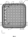
FIG. 2 is a front plan view of the storage organizing article ofFIG. 1 (with the center of the horizontal floor filled in with retention members 30); -
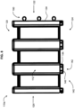
FIG. 3 is a side view of the storage organizing article ofFIG. 1 ; -
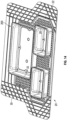
FIG. 4 is a cross-sectional view of the storage organizing article ofFIG. 1 taken along line 4-4 ofFIG. 3 ; -
FIG. 5 is an exploded isometric view of the vertical wall segments and the foundation of the storage organizing article ofFIG. 1 ; -
FIG. 6 is an enlarged view of a section of the foundation shown in the dashed line rectangular box RB1 ofFIG. 4 , before connection of the vertical wall segments to the foundation; -
FIG. 7 is an isometric view of the vertical wall segments fromFIG. 5 ; -
FIG. 8 is side view of a straight (linear) wall segment of the vertical wall segments ofFIG. 7 ; -
FIG. 9 is an isometric view of a corner (90 degree bend) wall segment of the vertical wall segment ofFIG. 7 ; -
FIG. 10 is an enlarged view of a section of the foundation shown in the dashed line rectangular box RB1 ofFIG. 4 , after connection of the vertical wall segments to the foundation; -
FIG. 11 is an enlarged view of a section of the foundation shown in the dashed line rectangular box RB2 ofFIG. 4 , after connection of the vertical wall segments to the foundation; and -
FIGS. 12A-12H are front plan views of the storage organizing article with various configurations of wall segments; -
FIG. 13 is an isometric bottom view of containers of the storage organizing article; and -
FIG. 14 is an isometric top view of the containers disposed on a floor mat. - It may be appreciated that the present disclosure is not limited in its application to the details of construction and the arrangement of components set forth in the following description or illustrated in the drawings. The invention(s) herein may be capable of other embodiments and of being practiced or being carried out in various ways. Also, it may be appreciated that the phraseology and terminology used herein is for the purpose of description and should not be regarded as limiting as such may be understood by one of skill in the art.
- Referring now to the figures, particularly
FIGS. 1-3 , there is shown a storage organizingarticle 10 according to the present disclosure. As shown, storage organizingarticle 10 comprises afoundation 20, which may be in a form of a tray or shallow container, particularly for a cargo region of the motor vehicle. For a front engine motor vehicle, the cargo region may be a trunk or other storage space typically rearward of a passenger seating region. For a rear engine motor vehicle, or an electric motor vehicle, the cargo region may be a trunk (which may be referred to as a frunk) or other storage space typically forward of a passenger seating region. In either instance, the cargo region may or may not be isolated from the passenger region) of a motor vehicle. - In certain embodiments, as shown by
FIGS. 1-3 , as well asFIGS. 4-5 ,foundation 20 comprises a polygonal (rectangular and more particularly square)horizontal floor 22. However, in other embodiments, thefoundation 20 may have a non-polygonal shape which follows, for example, the contours of a floor pan or vertical side walls defining a perimeter of the cargo area. For example, the one of more sides of thefoundation 20 may have one of more recesses and/or protrusions (e.g. seeFIG. 12H ) which correspond to protrusions and/or recesses in the cargo area, respectively. - As shown,
horizontal floor 22 is at least partially surrounded by a vertically raised perimeter rim 24 (which may be referred to a vertically raised containment wall). As shown, the,perimeter rim 24 extends continuously around thehorizontal floor 22. It should be understood that theperimeter rim 24 is preferably continuous/uninterrupted around thathorizontal floor 22 in that thehorizonal floor 22 is completely surrounded/enclosed by theperimeter rim 24 on all bordering sides (i.e. 360 degrees). In other embodiments, the vertically raisedperimeter rim 24 may be discontinuous/intermittent around thathorizontal floor 22. For example, the vertically raisedperimeter rim 24 may be discontinuous/intermittent around thathorizontal floor 22 at one or more sides of thefoundation 20/horizontal floor 22 or may be completely eliminated at one or more sides of thefoundation 20/horizontal floor 22. -
Foundation 20 may be particularly configured to contain items stored in a motor vehicle (e.g. groceries, sporting equipment, clothing). In certain embodiments,foundation 20 may be vehicle specific, i.e. dimensioned or otherwise configured to fit a predetermined motor vehicle. As shown,foundation 20 is formed as a single (monolithic) component, particularly by injection molding a thermoplastic composition comprising, essentially consisting of or consisting of a polyolefin (e.g. polypropylene (PP), acrylonitrile-butadiene-styrene (ABS), polyvinyl chloride (PVC)). - As shown by
FIGS. 1-5 ,horizontal floor 22 offoundation 20 preferably has a horizontal,planar base wall 28, with a plurality of repeatingretention members 30 to retainvertical wall 100 connectable thereto as explained in greater detail below. As shown, eachretention member 30 comprises a raised, spaced apart, vertically upward directedprojection 32. - As may be best shown by
FIG. 6 , eachprojection 32 is polygonal in cross-section, and more particularly a tetragonal (four sides) in cross-section. Even more particularly, eachprojection 32 is a square (four sides of equal length) in cross-section. As shown, eachprojection 32 is square with four, vertical,planar side walls 34 of equal length joined by rounded corners 36 (e.g. a fillet). An end of theprojection 32 has a horizontal, square,planar end wall 38, also with rounded corners. Eachprojection 32 has acenter 40, which, while not shown, is a center of a square as determined by the intersection of their respective diagonals. As shown, all theprojections 32 have a substantially identical geometry, i.e. having an identical geometry within manufacturing tolerances, andadjacent projections 32 are substantially equally spaced from one another, i.e. having an equal spacing within manufacturing tolerance. - Turning to
FIG. 2 , theprojections 32 may be arranged in a rectangular grid, which has theprojections 32 arranged in a first set of linear rows 1Rn (1R1, 1R2, etc.) and a second set of linear rows 2Rn (2R1, 2R2, etc.). As shown, with the first set of rows 1Rn, the rows 1Rn ofprojections 32 are arranged substantially parallel to one another, i.e. being parallel to each other within manufacturing tolerances. Similarly, with the second set of rows 2Rn, the rows 2Rn ofprojections 32 are also arranged substantially parallel to one another, i.e. being parallel to each other within manufacturing tolerances. Moreover, as shown, the first set of rows 1Rn ofprojections 32 and the second set of rows 2Rn ofprojections 32 are arranged in two directions/along two axes X and Y substantially perpendicular to one another, i.e. being preferably perpendicular to each other within manufacturing tolerances. - As perhaps shown best by
FIG. 2 , the first set of the plurality ofrows 1R comprises at least 2 rows, at least 3 rows, at least 4 rows, at least 5 rows, at least 6 rows, at least 7 rows, at least 8 rows, at least 9 rows, at least 10 rows, at least 11 rows, at least 12 rows or at least 13 rows. The second set of the plurality of rows 2R comprises at least 2 rows, at least 3 rows, at least 4 rows, at least 5 rows, at least 6 rows, at least 7 rows, at least 8 rows, at least 9 rows, at least 10 rows, at least 11 rows, at least 12 rows or at least 13 rows. - As also shown by
FIG. 2 , each row of the first set of the plurality ofrows 1R comprises at least 2retention members 30, at least 3retention members 30, at least 4retention members 30, at least 5retention members 30, at least 6retention members 30, at least 7retention members 30, at least 8retention members 30, at least 9retention members 30, at least 10retention members 30, at least 11retention members 30, at least 12retention members 30 or at least 13retention members 30. Each row of the second set of the plurality of rows 2R comprises at least 2retention members 30, at least 3retention members 30, at least 4retention members 30, at least 5retention members 30, at least 6retention members 30, at least 7retention members 30, at least 8retention members 30, at least 9retention members 30, at least 10retention members 30, at least 11retention members 30, at least 12retention members 30 or at least 13retention members 30. - It should be understood from the foregoing that a row of the first set of rows 1Rn comprises at least two
projections 32, and that similarly, a row of the second set of rows 2Rn comprises at least twoprojections 32. As such, the smallest grid according to the present disclosure is a two-by-two (i.e. 2x2) grid ofprojections 32, whereby the first set of rows 1Rn comprises two rows and the second set of rows 2Rn comprises two rows, each with twoprojections 32. It should also be understood that, given the first set of rows 1Rn and the second set of rows 2Rn are similarly composed ofprojections 32, the distinction between the first set of rows 2Rn and the second set of rows 2Rn delineates the directional arrangement of the sets of rows 1Rn and 2Rn with respect to one another, preferably shown being substantially perpendicular, i.e. being perpendicular to each other within manufacturing tolerances. It should also be understood that, to delineate the first set of rows 2Rn and the second set of rows 2Rn, the first set of rows 1Rn may also be referred to extending in an X-direction/axis of thefoundation 20/horizontal floor 22 and the second set of rows 2Rn may be referred to as extending in a Y-direction/axis of thefoundation 20/horizontal floor 22, which is substantially perpendicular to the first set of rows 1Rn, i.e. being perpendicular to each other within manufacturing tolerances. - Returning to
FIG. 6 , theengagement members 30/projections 32 may be arranged in asub-grouping 50 of fourengagement members 30/projections 32, which is used to engage/retain anengagement footing 140 of one or more vertical wall segments 110 as explained in greater detail below. As shown, asub-grouping 50 of fourprojections 32 are preferably arranged in a two-by-two (i.e. 2x2) sub-grouping, such that thecenter 40 of eachprojection 32 of thesub-grouping 50 of fourprojections 32 is substantially equal distance, i.e. being equal distance to one another within manufacturing tolerance, from acenter 40 of twoadjacent projections 32 of thesub-grouping 50 of fourprojections 32. Stated another way, thecenter 40 of eachprojection 32 of thesub-grouping 50 of fourprojections 32 provides a corner of animaginary square 52 linking thesub-grouping 50 of fourprojections 32. - As used herein, a sub-grouping may be understood as a plurality of
projections 32, such as at least two projections from the total number of available projections, that engage with theengagement footings 140. As may be appreciated, two opposing projections on opposite sides of thefooting 140 may sufficiently define an engagement receptacle for thefooting 140. Preferably, the sub-grouping 50 may therefore comprise two ormore projections 32 to define an engagement receptacle and therefore may also preferably comprise three or fourprojections 32. - From the figures, it should be understood that each
particular projection 32 is not limited to being a member of onesub-grouping 50, but that aparticular projection 32 may be a member of up to four sub-groupings 50. As such, it should be understood that afirst sub-grouping 50 and a second-sub-grouping 50 are to be considered twodifferent sub-groupings 50 if they do not share all thesame projections 32 in common. Stated another way, if twosub-groupings 50 have at least one uncommon (unshared)projection 32, then the two sub-groupings 50 are different sub-groupings 50. In a case where twosub-groupings 50 do not share anyprojections 32 in common, the sub-groupings 50 and theirrespective retention members 30 may be referred to as being exclusive to one another, in addition to being considereddifferent sub-groupings 50. - Also from the figures, it should be understood that a
sub-grouping 50 ofprojections 32 may form two sets of two rows ofprojections 32, with the rows of each set preferably extending substantially parallel to each other, i.e. being parallel within manufacturing tolerance, respectively, and the sets of rows extending substantially to one another, i.e. being perpendicular within manufacturing tolerance. - As further shown by
FIGS. 1-3 ,5 and7-9 ,storage organizing article 10 further comprises avertical wall 100 formed of separate and distinct components fromfoundation 20. Thevertical wall 100 includesvertical wall segments - As shown by
FIGS. 7-8 ,wall segment 110a has afront face 112, back face 116 (opposite front face 112),top face 120, bottom face 124 (opposite top face 120) and end faces 128, 132 (opposite one another).Bottom face 124 includes at least one engagement footing 140 (shown as a plurality) to engage withfoundation 20 andmount wall segment 110a tofoundation 20. - As may be best shown by
FIG. 8 , eachengagement footing 140 comprises a verticallydownward projection 142 located on thebottom face 124 of thewall segment 110a which, as explained in greater detail below, engages between and with the vertically upward directedprojections 32/retention members 30 offoundation 20. As shown byFIG. 10 , eachprojection 142 is preferably cylindrical in cross-section, with a vertical,cylindrical side wall 144. Referring back toFIG. 8 , the end of theprojection 142 has a horizontal, circular,planar end wall 146. Eachprojection 142 has a center 150 (seeFIG. 10 ), which is the center of a constant diameter of thecylindrical side wall 144 and thecircular end wall 146. As shown, all the engagement footings 1401projections 142 have a substantially identical geometry, i.e. having an identical geometry within manufacturing tolerances. - In order to assemble, and releasably mechanically connect,
vertical wall segment 110a, tofoundation 20 with a releasable mechanical connection, each verticallydownward projection 142 is directed (pushed) into an engagement receptacle 54 (seeFIG. 6 ) formed between a sub-grouping 50 of the verticallyupward projections 32 of thefoundation 20, and fits in theengagement receptacle 54 with a friction fit, which also may be known as an press (interference) fit or pressure grip fit connection. A friction fit connection may be understood herein as a connection formed between two components which solely relies upon friction to inhibit separation of the components, for example by one of the components being pressed into the other component such that at least one of the components is compressed (deformed) against one another. - As also shown in
FIG. 6 , preferably, theretention members 30/projections 32 are substantially equally spaced around acenter 56 of thereceptacle 54, i.e. equally spaced within manufacturing tolerance. More particularly, as shown inFIG. 5 , eachprojection 142 is pushed in anengagement receptacle 54 by moving the wall segments 110 along an assembly/disassembly (connection/disconnection) Z-direction/axis, which is transverse to thehorizontal floor 22 offoundation 20, which may be understood as being vertical to thehorizontal floor 22 offoundation 20, and more preferably perpendicular to thehorizontal floor 22 offoundation 20. - Now referring to
FIG. 10 , once in eachengagement receptacle 54, preferably, a portion of each of four 90 degree arcs, of the verticalcylindrical side wall 144 of theprojection 142 of the wall segment 110, contacts against one of theplanar side walls 34 of the adjacent surroundingprojections 32 of thefoundation 20 to form the releasable interference fit of theprojection 142 with theprojections 32 within theengagement receptacle 54. Conversely, theprojections 142/engagement footings 140 of wall segments 110 may be removed from theengagement receptacles 54, respectively, by being pulled out of theengagement receptacles 54 in a direction opposite to being inserted in theengagement receptacles 54 to release the connection. - In
FIG. 10 , the portion of each of the four 90 degree arcs of the verticalcylindrical side wall 144 of theprojection 142 of the wall segment 110, which contacts against one of theplanar side walls 34 of the adjacent surroundingprojections 32 of thefoundation 20 to form the releasable interference fit of theprojection 142 with theprojections 32 may deform in forming the interference fit. More particularly, as shown, the portion of each of the four 90 degree arcs of the verticalcylindrical side wall 144 of theprojection 142 of the wall segment 110, which contacts against one of theplanar side walls 34 of the adjacent surroundingprojections 32 may deform to form a planar surface portion which mates against the planar surface of the correspondingprojection 32. Alternatively, prior to assembly, each portion of thecylindrical side wall 144 of theprojection 142 of the wall segment 110, which contacts against one of theplanar side walls 34 of the adjacent surroundingprojections 32 may include a flat (i.e. a planar surface) to form the interference fit. - While not necessary, the vertical,
cylindrical side wall 144 of eachprojection 142 of the wall segment 110 may be equal in vertical length to the vertical,planar side walls 34 of theprojections 32 of thefoundation 20 such that theplanar end wall 146 of eachprojection 142 of the wall segment 110 may contact against thebase wall 28 of thefoundation 20 when fully inserted in theengagement receptacles 54. This may therefore provide additional vertical and horizontal stability of the wall segment 110 when affixed to thefoundation 20. - Referring again to
FIGS. 7 and8 , eachend face wall segment 110a preferably includes at least one (first) connector 158 to releasably mechanically connect with a (second) corresponding (mating) connector 158 of anadjacent wall segment end face wall segment 110a preferably includes a plurality of connectors 158 to connect with corresponding (mating) connectors 158 of anadjacent wall segment - More preferably, as shown,
end face 128 ofwall segment 110a includes a plurality of female connectors 160 to receive amale connector 180 disposed on anend face 132 ofwall segment 110b. Whilemale connector 180 ofwall segment 110b is not shown inFIG. 7 , it should be understood that themale connector 180 ofwall segment 110b is the same as themale connector 180 ofwall segment 110d as shown, as well as all the othermale connectors 180. The same may be said for female connectors 160. - As shown, female connector 160 comprises a
socket 162 to receive aprong 182 ofmale connector 180. More particularly, thesocket 162 comprises an elongated, tubular,wall 164 disposed on anend wall 130 of connectingend face 128 ofwall segment 110a.Socket 162 further comprises acylindrical cavity 166 withintubular wall 164, which an accessable via acircular opening 168 at one end of thetubular wall 164, as well as aslot 170 extending along a longitudinal length (X-direction/axis) of thetubular wall 164, resulting in thetubular wall 164 taking on a form of a C-shape. -
Prong 182 ofmale connector 180 further comprises an elongatedcylindrical post 184 disposed at a distal end of anelongated rib 186, which is disposed on theend wall 134 ofend face 132 ofwall segment 110b. - When assembled, post 184 of
male connector 180 resides incylindrical cavity 166 upon enteringcavity 166 viacircular opening 168, whilerib 186 occupiesslot 170. - As such, the
wall segments 110, 110c are releasably mechanically connected to one another via a positive mechanical engagement, as opposed to the interference (friction/press) fit to thefoundation 20. - More particularly,
socket 162 andprong 182 are assembled by moving one or both of thewall segment 110a and thewall segment 110b along the X-direction/axis.Wall segment - In contrast,
wall segments wall segments - After first being fully assembled,
wall segments 110a-e are attached tofoundation 20, with the Z-direction/axis traverse to the X-direction/axis and Y-direction/axis the one another, and more preferably perpendicular to one another. More particularly, the X-direction/axis and Y-direction/axis are horizontal, and thus parallel to thehorizontal floor 22 offoundation 20, while the Z-axis is vertical, and thus perpendicular to thehorizontal floor 22 offoundation 20. In such manner, the wall segments 110 are preferably inhibited from separating from one another as long as the wall segments 110 remain connected to thefoundation 20. By virtue of the orientation of the assembly/disassembly axes, thewall segments 110a-e are to be disassembled (separated) from foundation 110 before being disassembled (separated) from each other. Similarly, when assembled, thewall segments 110a-e are to be assembled (connected) to each other before being assembled (connected) to the foundation 110. - As shown in
FIG. 10 , theengagement footing 140, and more particularly thecylindrical projection 142, is formed solely by the straight (linear)wall segment 110a. However, as shown inFIG. 11 , theengagement footing 140, and more particularly thecylindrical projection 142, is formed by twoadjacent wall segments engagement footing 140, and more particularly thecylindrical projection 142, is formed of a first (half)projection portion 152 provided by thevertical wall segment 110a, and a second (half)projection portion 152 provided by thevertical wall segment 110b. - In light of the foregoing, and as shown by the figures, it should be understood that each
vertical wall segment 110a-110e of the plurality of vertical wall segments 110 comprises at least a portion of at least oneengagement footing 140 of the plurality ofengagement footings 140. As also shown by the figures, at least one vertical wall segment 110 of the plurality of vertical wall segments 110 comprises at least oneengagement footing 140 of the plurality of engagement footings 140 (e.g. 110a, 110b, 110c). As also shown by the figures, at least one vertical wall segment 110 of the plurality of vertical wall segments 110 comprises more than oneengagement footing 140 of the plurality of engagement footings 140 (e.g. 110a, 110b, 110c). As also shown by the figures, at least one vertical wall segment 110 of the plurality of vertical wall segments 110 comprises at least twoengagement footings 140 of the plurality of engagement footings 140 (e.g. 110a). - As shown by
FIGS. 1-3 ,5 and7 ,vertical wall 100 comprises a straight (linear)wall segment 110a (e.g. seeFIG. 8 individually), two corner (90 degree bend)wall segments FIG. 9 individually), and twoend caps linear wall segments 110a and/orcorner wall segments vertical wall 100. Whilevertical wall 100 is shown in a U-shaped configuration, it should be understood that numerous configurations are possible with thevarious wall segments 110a-110e, and that additional wall segments 100a-110e may be used in further repetition orwall segments 110a-110e may be eliminated. For example, a polygonal (tetragonal) shape (four sides)vertical wall 100 may be created by adding three additional straight (linear)wall segment 110a and twocorner wall segments 110e, 100d, whileend caps 110c, 1 10e may be eliminated. Such may be seen, for example inFIG. 12A. FIGS. 12A-12H show other exemplary configurations/layouts of thevertical wall 100 according to the present disclosure. It should be understood that the variousvertical walls 100 shown in each ofFIGS. 12A-12H are not exclusive to any particular configuration and can be changed or combined with any vertical wall(s) on any other illustrated configuration as feasible. - The
wall segments 110a-110e may be formed by injection molding a thermoplastic composition comprising, essentially consisting of or consisting of a polyolefin (e.g. polypropylene (PP), acrylonitrile-butadiene-styrene (ABS), polyvinyl chloride (PVC)). Wall segments 1 10-1 10e may also be formed using other molding techniques such as blow molding. Also, in order to consolidate pieces, straight (linear)wall segment 110a may incorporate a living hinge which allows the linear wall segment 100a to convert to a corner wall segment when bent about the hinge. As such, the linear wall segment and corner wall segment could be consolidated into a single molded part/component. - Referring now to
FIG. 13 ,engagement footings 140 may be disposed on a bottom of acontainer 200, such as a storage bin, which may be used to hold, for example, durable or consumable goods such as groceries, sporting equipment and clothing. As shown, theengagement footings 140 may be disposed about a periphery of the bottom of thecontainer 200. More particularly,engagement footings 140 may be disposed on ahorizontal bottom wall 202 of thecontainer 200, which is disposed adjacent a surroundingvertical side wall 204. -
Container 200 may have a storage volume of at least 1 liter, such as at least 2, 3, 4, 5, 6, 7, 8, 9, 10, 11, 12, 13, 14, 15, 16, 17, 18, 19, 20, 21, 22, 23, 24, 25, 26, 27, 28, 29, 30, 31, 32, 33, 34, 35, 36, 37, 38, 39, 40, 41, 42, 43, 44, 45, 46, 47, 48, 49, 50, 51, 52, 53, 54, 55, 56, 57, 58, 59, 60, 61, 62, 63, 64, 65, 66, 67, 68, 69, 70, 71, 72, 73, 74, 75, 76, 77, 78, 79, 80, 81, 82, 83, 84, 85, 86, 87, 88, 89, 90, 91, 92, 93, 94, 95, 96, 97, 98, 99 or 100 liters.Container 200 may have a volume range, for example, of 1-100 liters, 4-100 liters, 4-50 liters, 4-25 liters, 10-50 liters, 15-50 liters, 20-50 liters, 25-50 liters, 51-100 liters, 51-90 liters, 51-80 liters, 51-70 liters, 51-60 liters, 55-100 liters, 60-100 liters, 70-100 liters, 80-100 liters and 90-100 liters. As shown,container 200 is a one-piece, injection molded, polygonal, plastic container, which may be formed of a thermoplastic polyolefin, such as polypropylene or polyethylene.Container 200 may be capable of storing flowable or flowing compositions, including bulk material in solid form (e.g. soil, mulch, stone), and liquid form (e.g. water). - Referring now to
FIG. 14 , theengagement footings 140 of one or more same size ordifferent size containers 200 may be releasably connected withfoundation 20. As shown,foundation 20 may be in the form of a floor mat, particularly for a cargo region of the motor vehicle. As with previous figures,foundation 20 comprises ahorizontal floor 22 having aplanar base wall 28, as well as a plurality of repeatingretention members 30, which each comprise a raised, spaced apart, vertically upward directedprojection 32. - As shown, as with earlier description, the
projections 32 may be arranged in a rectangular grid, which has theprojections 32 arranged in a first set of linear rows 1Rn and a second set of linear rows 2Rn, particularly arranged in two directions/along two axes X and Y substantially perpendicular to one another, i.e. being preferably perpendicular to each other within manufacturing tolerances. - As shown, as with earlier description, the
engagement members 30/projections 32 may be arranged in asub-grouping 50 of fourengagement members 30/projections 32, which is used to releasably connect with anengagement footing 140 of thecontainer 200. As such, it should be understood that the description regarding such accompanying the earlier figures applies equally toFIGS. 13 and14 . - While a preferred embodiment of the present invention(s) has been described, it should be understood that various changes, adaptations and modifications can be made therein without departing from the spirit of the invention(s) and the scope of the appended claims. The scope of the invention(s) should, therefore, be determined not with reference to the above description, but instead should be determined with reference to the appended claims along with their full scope of equivalents. Furthermore, it should be understood that the appended claims do not necessarily comprise the broadest scope of the invention(s) which the applicant is entitled to claim, or the only manner(s) in which the invention(s) may be claimed, or that all recited features are necessary.
-
- 10
- storage organizing article
- 20
- foundation
- 22
- horizontal floor
- 24
- perimeter rim
- 28
- base wall
- 30
- retention member
- 32
- projection
- 34
- planar side wall
- 36
- rounded corner
- 38
- end wall
- 40
- center
- 50
- sub-grouping of retention members/projections
- 52
- imaginary square
- 54
- engagement receptacle
- 56
- center of engagement receptacle
- 100
- vertical wall
- 110
- vertical wall segments (110a-110e)
- 112
- front face
- 116
- back face
- 120
- top face
- 124
- base face
- 128
- connecting end face
- 130
- end wall
- 132
- connecting end face
- 134
- end wall
- 140
- engagement footing
- 142
- projection
- 144
- cylindrical side wall
- 146
- end wall
- 150
- center
- 152
- first portion of footing/projection
- 154
- second portion of footing/projection
- 158
- connector
- 160
- female connector
- 162
- socket
- 164
- tubular wall
- 166
- cylindrical cavity
- 168
- circular opening
- 170
- slot
- 180
- male connector
- 182
- prong
- 184
- cylindrical post
- 186
- rib
- 200
- container
- 202
- bottom wall
- 204
- side wall
- X
- direction/axis
- Y
- direction/axis
- Z
- direction/axis
- RB1
- rectangular box
- RB2
- rectangular box
Claims (15)
- A storage organizing article, comprising:a foundation comprising a horizontal floor;at least one container having a plurality of engagement footings;wherein the container is releasably connectable to the foundation via the plurality of engagement footings of the container;wherein the horizontal floor has a base wall, a plurality of retention members and a plurality of engagement receptacles;wherein each engagement receptacle of the plurality of engagement receptacles is formed by a sub-grouping of the plurality of retention members, respectively; andwherein, when the foundation and the container are connected, each of the engagement footings of the plurality of engagement footings is respectively disposed in one of the engagement receptacles of the plurality of engagement receptacles and forms a releasable interference fit with the sub-grouping of the plurality of retention members forming the engagement receptacle.
- The storage organizing article of claim 1, wherein each of the engagement footings of the plurality of engagement footings comprises a projection;wherein each retention member of each sub-grouping of the plurality of retention members comprises a projection which projects vertically upward relative to the base wall; andwherein, when the foundation and the container are connected, each projection of each of the engagement footings is disposed in one of the engagement receptacles and forms a releasable interference fit with each of the projections of each sub-grouping forming the engagement receptacle.
- The storage organizing article of claim 2, wherein the projection of each of the engagement footings is substantially identical.
and wherein preferably the projection of each of the engagement footings is cylindrical in cross-section. - The storage organizing article of claim 2, wherein the projection of each retention member of each sub-grouping is substantially identical and
wherein preferably the projection of each retention member of each sub-grouping is polygonal, most preferably square in cross-section. - The storage organizing article of claim 1, wherein each engagement receptacle of the plurality of engagement receptacles formed by a sub-grouping of the plurality of retention members is formed by at least two retention members.
- The storage organizing article of claim 1, wherein each sub-grouping of the plurality of retention members is formed by four retention members.
- The storage organizing article of claim 6, wherein the four retention members of each sub-grouping are substantially equally spaced around a center of each engagement receptacle of the plurality of engagement receptacles, respectively.
- The storage organizing article of claim 1, wherein the plurality of retention members are arranged in a plurality of rows;wherein a first set of the plurality of rows are substantially parallel to one another;wherein a second set of the plurality of rows are substantially parallel to one another; andwherein the first set of the plurality of rows and the second set of the plurality of rows are substantially perpendicular to one another.
- The storage organizing article of claim 8, wherein the first set of the plurality of rows comprises at least 2 rows, at least 3 rows, at least 4 rows, at least 5 rows, at least 6 rows, at least 7 rows, at least 8 rows, at least 9 rows, at least 10 rows, at least 11 rows, at least 12 rows or at least 13 rows; and
the second set of the plurality of rows comprises at least 2 rows, at least 3 rows, at least 4 rows, at least 5 rows, at least 6 rows, at least 7 rows, at least 8 rows, at least 9 rows, at least 10 rows, at least 11 rows, at least 12 rows or at least 13 rows. - The storage organizing article of claim 8, wherein each row of the first set of the plurality of rows comprises at least 2 retention members, at least 3 retention members, at least 4 retention members, at least 5 retention members, at least 6 retention members, at least 7 retention members, at least 8 retention members, at least 9 retention members, at least 10 retention members, at least 11 retention members, at least 12 retention members or at least 13 retention members; and
wherein each row of the second set of the plurality of rows comprises at least 2 retention members, at least 3 retention members, at least 4 retention members, at least 5 retention members, at least 6 retention members, at least 7 retention members, at least 8 retention members, at least 9 retention members, at least 10 retention members, at least 11 retention members, at least 12 retention members or at least 13 retention members. - The storage organizing article of claim 1, wherein the base wall is planar.
- The storage organizing article of claim 1, wherein the foundation further comprises a perimeter rim which at least partially, preferably completely surrounds the horizontal floor.
- The storage organizing article of claim 1, wherein the foundation is in a form of a floor mat.
- The storage organizing article of claim 1, wherein the foundation and/or the container is formed of an injection molded thermoplastic composition.
- The storage organizing article of claim 1, wherein the container has a storage volume in a range of 1liter to 100 liters.
Applications Claiming Priority (1)
| Application Number | Priority Date | Filing Date | Title |
|---|---|---|---|
| US17/643,217 US20220153201A1 (en) | 2020-10-26 | 2021-12-08 | Storage organizing article and system |
Publications (1)
| Publication Number | Publication Date |
|---|---|
| EP4194271A1 true EP4194271A1 (en) | 2023-06-14 |
Family
ID=84688358
Family Applications (1)
| Application Number | Title | Priority Date | Filing Date |
|---|---|---|---|
| EP22211384.7A Withdrawn EP4194271A1 (en) | 2021-12-08 | 2022-12-05 | Storage organizing article and system |
Country Status (2)
| Country | Link |
|---|---|
| US (1) | US20220153201A1 (en) |
| EP (1) | EP4194271A1 (en) |
Citations (2)
| Publication number | Priority date | Publication date | Assignee | Title |
|---|---|---|---|---|
| US5976672A (en) * | 1996-11-01 | 1999-11-02 | Loadhandler Industries, Inc. | Cargo liner and cargo holder system |
| US20170027411A1 (en) * | 2015-07-30 | 2017-02-02 | FRIES Planungs - und Marketinggesellschaft m.b.H. | Carrier arrangement for storing and/or transporting and/or cleaning dishware or other items |
Family Cites Families (1)
| Publication number | Priority date | Publication date | Assignee | Title |
|---|---|---|---|---|
| US11577661B2 (en) * | 2020-10-26 | 2023-02-14 | Thermoflex Corp. | Storage organizing article and system |
-
2021
- 2021-12-08 US US17/643,217 patent/US20220153201A1/en not_active Abandoned
-
2022
- 2022-12-05 EP EP22211384.7A patent/EP4194271A1/en not_active Withdrawn
Patent Citations (2)
| Publication number | Priority date | Publication date | Assignee | Title |
|---|---|---|---|---|
| US5976672A (en) * | 1996-11-01 | 1999-11-02 | Loadhandler Industries, Inc. | Cargo liner and cargo holder system |
| US20170027411A1 (en) * | 2015-07-30 | 2017-02-02 | FRIES Planungs - und Marketinggesellschaft m.b.H. | Carrier arrangement for storing and/or transporting and/or cleaning dishware or other items |
Also Published As
| Publication number | Publication date |
|---|---|
| US20220153201A1 (en) | 2022-05-19 |
Similar Documents
| Publication | Publication Date | Title |
|---|---|---|
| EP4232322B1 (en) | Storage organizing article and system | |
| US5810187A (en) | Drawer organizer | |
| US6966155B2 (en) | Mat perimeter system | |
| BE1020219A3 (en) | STORAGE VOLUME. | |
| US6886787B2 (en) | Dolly for supporting and transporting bakery trays | |
| US6209891B1 (en) | Workseat cart | |
| NL1010321C2 (en) | Wafer carrier. | |
| US6074234A (en) | Connector assembly with locking structures disposed in concave exterior corners | |
| US5454634A (en) | Unitary interlocking frame for storage containers | |
| US20110303808A1 (en) | Can holder | |
| EP4194271A1 (en) | Storage organizing article and system | |
| US20030141300A1 (en) | Crate locking device | |
| US20210130043A1 (en) | Container made of injection-molded plastic | |
| CN222137285U (en) | Material box, goods shelf and storage system | |
| KR101419177B1 (en) | Apparatus for combining prefabricated storage box | |
| CN212196512U (en) | Storage container | |
| US5989072A (en) | Connection system with terminal/cavity combination | |
| JP6242225B2 (en) | Storage case | |
| JPH0752019Y2 (en) | Synthetic resin pallet | |
| CN215795136U (en) | Sheet metal plastic sucking disc | |
| CN113734556A (en) | Diversified combination formula blister supporting plate | |
| JP2003300583A (en) | Plate-like transport box | |
| CN215157016U (en) | Packaging frame and robot assembly | |
| CA2185066A1 (en) | Interconnectible spacers for supporting an article from a base surface | |
| JP3023112U (en) | Partition board |
Legal Events
| Date | Code | Title | Description |
|---|---|---|---|
| STAA | Information on the status of an ep patent application or granted ep patent |
Free format text: STATUS: UNKNOWN |
|
| PUAI | Public reference made under article 153(3) epc to a published international application that has entered the european phase |
Free format text: ORIGINAL CODE: 0009012 |
|
| STAA | Information on the status of an ep patent application or granted ep patent |
Free format text: STATUS: THE APPLICATION HAS BEEN PUBLISHED |
|
| AK | Designated contracting states |
Kind code of ref document: A1 Designated state(s): AL AT BE BG CH CY CZ DE DK EE ES FI FR GB GR HR HU IE IS IT LI LT LU LV MC ME MK MT NL NO PL PT RO RS SE SI SK SM TR |
|
| STAA | Information on the status of an ep patent application or granted ep patent |
Free format text: STATUS: THE APPLICATION IS DEEMED TO BE WITHDRAWN |
|
| 18D | Application deemed to be withdrawn |
Effective date: 20231215 |