EP4194216B1 - Multiple size media holder assembly for a mobile printer - Google Patents
Multiple size media holder assembly for a mobile printer Download PDFInfo
- Publication number
- EP4194216B1 EP4194216B1 EP23150760.9A EP23150760A EP4194216B1 EP 4194216 B1 EP4194216 B1 EP 4194216B1 EP 23150760 A EP23150760 A EP 23150760A EP 4194216 B1 EP4194216 B1 EP 4194216B1
- Authority
- EP
- European Patent Office
- Prior art keywords
- hub
- height
- media
- spring
- triangular
- Prior art date
- Legal status (The legal status is an assumption and is not a legal conclusion. Google has not performed a legal analysis and makes no representation as to the accuracy of the status listed.)
- Active
Links
Images




Classifications
-
- B—PERFORMING OPERATIONS; TRANSPORTING
- B41—PRINTING; LINING MACHINES; TYPEWRITERS; STAMPS
- B41J—TYPEWRITERS; SELECTIVE PRINTING MECHANISMS, i.e. MECHANISMS PRINTING OTHERWISE THAN FROM A FORME; CORRECTION OF TYPOGRAPHICAL ERRORS
- B41J15/00—Devices or arrangements of selective printing mechanisms, e.g. ink-jet printers or thermal printers, specially adapted for supporting or handling copy material in continuous form, e.g. webs
- B41J15/04—Supporting, feeding, or guiding devices; Mountings for web rolls or spindles
- B41J15/042—Supporting, feeding, or guiding devices; Mountings for web rolls or spindles for loading rolled-up continuous copy material into printers, e.g. for replacing a used-up paper roll; Point-of-sale printers with openable casings allowing access to the rolled-up continuous copy material
-
- B—PERFORMING OPERATIONS; TRANSPORTING
- B65—CONVEYING; PACKING; STORING; HANDLING THIN OR FILAMENTARY MATERIAL
- B65H—HANDLING THIN OR FILAMENTARY MATERIAL, e.g. SHEETS, WEBS, CABLES
- B65H16/00—Unwinding, paying-out webs
- B65H16/02—Supporting web roll
- B65H16/06—Supporting web roll both-ends type
-
- B—PERFORMING OPERATIONS; TRANSPORTING
- B41—PRINTING; LINING MACHINES; TYPEWRITERS; STAMPS
- B41J—TYPEWRITERS; SELECTIVE PRINTING MECHANISMS, i.e. MECHANISMS PRINTING OTHERWISE THAN FROM A FORME; CORRECTION OF TYPOGRAPHICAL ERRORS
- B41J11/00—Devices or arrangements of selective printing mechanisms, e.g. ink-jet printers or thermal printers, for supporting or handling copy material in sheet or web form
- B41J11/0025—Handling copy materials differing in width
-
- B—PERFORMING OPERATIONS; TRANSPORTING
- B41—PRINTING; LINING MACHINES; TYPEWRITERS; STAMPS
- B41J—TYPEWRITERS; SELECTIVE PRINTING MECHANISMS, i.e. MECHANISMS PRINTING OTHERWISE THAN FROM A FORME; CORRECTION OF TYPOGRAPHICAL ERRORS
- B41J13/00—Devices or arrangements of selective printing mechanisms, e.g. ink-jet printers or thermal printers, specially adapted for supporting or handling copy material in short lengths, e.g. sheets
- B41J13/10—Sheet holders, retainers, movable guides, or stationary guides
-
- B—PERFORMING OPERATIONS; TRANSPORTING
- B65—CONVEYING; PACKING; STORING; HANDLING THIN OR FILAMENTARY MATERIAL
- B65H—HANDLING THIN OR FILAMENTARY MATERIAL, e.g. SHEETS, WEBS, CABLES
- B65H2301/00—Handling processes for sheets or webs
- B65H2301/40—Type of handling process
- B65H2301/41—Winding, unwinding
- B65H2301/413—Supporting web roll
- B65H2301/4134—Both ends type arrangement
- B65H2301/41346—Both ends type arrangement separate elements engaging each end of the roll (e.g. chuck)
-
- B—PERFORMING OPERATIONS; TRANSPORTING
- B65—CONVEYING; PACKING; STORING; HANDLING THIN OR FILAMENTARY MATERIAL
- B65H—HANDLING THIN OR FILAMENTARY MATERIAL, e.g. SHEETS, WEBS, CABLES
- B65H2402/00—Constructional details of the handling apparatus
- B65H2402/40—Details of frames, housings or mountings of the whole handling apparatus
- B65H2402/41—Portable or hand-held apparatus
-
- B—PERFORMING OPERATIONS; TRANSPORTING
- B65—CONVEYING; PACKING; STORING; HANDLING THIN OR FILAMENTARY MATERIAL
- B65H—HANDLING THIN OR FILAMENTARY MATERIAL, e.g. SHEETS, WEBS, CABLES
- B65H2402/00—Constructional details of the handling apparatus
- B65H2402/50—Machine elements
- B65H2402/54—Springs, e.g. helical or leaf springs
-
- B—PERFORMING OPERATIONS; TRANSPORTING
- B65—CONVEYING; PACKING; STORING; HANDLING THIN OR FILAMENTARY MATERIAL
- B65H—HANDLING THIN OR FILAMENTARY MATERIAL, e.g. SHEETS, WEBS, CABLES
- B65H2801/00—Application field
- B65H2801/03—Image reproduction devices
- B65H2801/12—Single-function printing machines, typically table-top machines
Definitions
- the present invention relates to a media holder and a printer including the media holder.
- Some mobile printers have designs to accommodate more than one media core size. Generally these designs require some disassembly or part replacement to adapt to each new core size. This exchange takes time and can delay printing.
- printers have switching mechanisms which alternate media core hubs to accommodate more than one media core size.
- these mechanisms may take up additional and valuable real estate in the printer. Additionally, the mechanisms do require operator to actively select the correct media hub as opposed to simply using another media core size without changes the printer.
- WO 2007/037173 A1 discloses a roll body holding device and recording device in which, to hold a roll body having a small inner diameter paper tube by a roll body holding device, a projection of a holding device body is inserted into the paper tube without installing an adapter and a first elastic section is made to be in pressure contact with the inner surface of the paper tube.
- the present invention embraces a multiple size media holder assembly for a printer and a printer employing such a media holder assembly.
- the present invention includes a printer (10), a media holder assembly (11), comprised of a pair of opposedly mounted media holder subassemblies (12a & 12b).
- the distance (28) between the media holder subassemblies (12a & 12b) is sized to accommodate a media roll (not shown).
- FIG. 1A shows a magnified view of media sub-assembly (12a).
- Basic components of the media sub-assembly (12a) include a base (13), a platform (15) secured to the base, and 3 hubs: first hub (20), second hub (30) and third hub (40), each sized to accommodate the inner diameters of three varying sized media rolls (not shown) and each having an exterior surface (not visible in this view) to support three media rolls of varying inner diameters.
- the base (13) and the platform (15) can be combined in a single part (not shown) or in the alternative, the base and the platform may be composed of multiple parts.
- FIG 2 shows an exploded view of the media sub-assembly (12a) of Figure 1 .
- the media sub-assembly (12a) includes a base (13) and platform (15).
- the platform (15) is secured to the (base).
- the platform (15) and base (13) are shown secured with a fastener (14) which can be a screw and washer as shown, or other fasteners known in the art.
- the platform (15) and the base (13) can be molded to form a single part.
- the platform (15) has a flange (50) and has a central cylindrical depression (16).
- the cylindrical depression (16) has an inner wall (17), a bottom (18), and at least one stop on the inner wall of the cylindrical depression (not visible in this view).
- the stop which will be discussed in more detail in conjunction with Figures 4 , 5 , 6 , 7 and 8 could be an annular groove, one or more protruding flanges, one or more of recesses, cutouts, or notches on or in the inner wall (17), or the like.
- Protruding from the center of the cylindrical depression (16) is the first hub (20).
- the first hub (20) is sized for a first media roll (not shown).
- the first hub has an exterior surface (23) to support the first media roll.
- the first hub is depicted as having a circular cross-section, but other cross-sectional shape are contemplated based upon the first hub's (20) exterior surface (23) supporting the first media roll.
- the cross-sectional shapes of the first hub is triangular.
- the first hub (20) may have any cross-sectional shape which can be encompassed by the inner diameter, usually circular, of the media roll and adequately supports it. It can be seen from the Figure that the height of the first hub (20) extends higher than the flange (50). Other features of the first hub (20) will be described in conjunction with subsequent Figures which show those features.
- a first spring (24) concentric to the first hub (20) is disposed in the cylindrical depression (16).
- the second hub (30) is sized for a second media roll (not shown) and has an exterior surface (32) for supporting the second media roll.
- the second hub (30) may be ring-shaped as shown in Figure 2 , or any shape which will support the second media roll.
- the second hub (30) may have any cross-sectional geometric shape which fits within the inner diameter, usually circular, of the media roll and around the first hub (20).
- the cross-sectional shapes of the second hub is triangular and has an exterior surface (32) which will support the second media roll.
- the second hub (30) is concentric to the first hub (20) and has a height less than the height of the first hub (20).
- the second hub (30) is supported by the first spring (24).
- the second hub (30) may be profiled to fit over the first spring (24) in the cylindrical depression (16).
- the second hub (30) may be supported by the first spring (24) by a number of other mechanisms or constructions.
- the second hub (30) may be notched to be supported by the first spring (24).
- the second hub (30) When the media sub-assembly (12a) is assembled, the second hub (30) is slidably engaged to the first hub (20).
- the second hub (30) With at least one retainer (33) which is pictured as a flange, tab, or protrusion on the inner diameter (31) of the second hub (30).
- the first hub (20) is correspondingly provided with a stop (not visible in this Figure 2 ) on the exterior surface (23) of the first hub (20) under or in which the retainer (33) on the second hub (30) is disposed.
- the stop on the exterior surface (23) of the first hub (20) may be a continuous annular groove for receiving the at least one retainer (33) of the second hub (30).
- the stop could be one or more flanges protruding from the exterior surface (21) of the first hub (20).
- the at least one stop on the exterior surface (23) of the first hub could be one or more recesses, cutouts, or notches in the exterior surface (23) of the first hub designed to receive the at least one retainer (33) of the second hub (30). The slidable engagement will be discussed in more detail hereinafter.
- the third hub (40) and the second hub (30) are in slidable engagement when the media sub-assembly (12a) is fully assembled.
- the slidable engagement will be discussed in more detail hereinafter in conjunction with Figures (4 , 5 , 6 , 7 , and 8 ).
- the outermost hub in Figure 2 this being the third hub (40), is slidably engaged to the inner wall (17) of the cylindrical depression (16).
- the third hub (40) may be provided with at least one retainer (46) which is pictured as a flange, tab, or protrusion on the exterior surface (42) of the third hub (40).
- the inner wall (17) of the cylindrical depression (16) is correspondingly provided with a stop (not visible in this Figure) under or in which the retainer (46) on the third hub (40) is disposed.
- the stop on the inner wall (17) of the cylindrical depression (16) may be a continuous annular groove for receiving the at least one retainer (46) of the third hub (40).
- the stop could be one or more flanges protruding from the inner wall (17).
- the at least one stop on the inner wall (17) could be one or more recesses, cutouts, or notches in the inner wall (17) designed to receive the at least one retainer (46) of the third hub (40). The slidable engagement will be discussed in more detail hereinafter.
- Figure 3 is a cross-sectional view of the media holder sub-assembly (12a) of Figure 2 , now fully assembled without a media roll in place.
- first spring (24) and the second spring (26) bias the second hub (30) and the third hub (40) respectively to a height level with the height of the first hub (20) and above that of the flange (50).
- the first hub (20) has a stop (22) on the exterior surface (23).
- the stop (22) is a recess or cutout disposed near the bottom (21) of the first hub (20).
- the stop (22) could be one or more tabs or flanges protruding from the exterior surface (23) or notches in the exterior surface (23).
- the stop (22) may be a continuous annular groove or a series of recesses, cutouts, or notches.
- the second hub (30) may be provided with at least on retainer (33) on the inner diameter (31).
- the at least one retainer (33) is illustrated as a tab or flange on the inner diameter (31) as discussed hereinbefore.
- the at least one retainer (33) is disposed in the stop (22) of the first hub (20).
- the stop (22) limits the biasing of the second hub (30) by the first spring (24).
- the cylindrical depression (16) is provided with at least one stop (19).
- the at least one stop (19) is a recess or cutout in the inner wall (17).
- the recess may be a continuous annular groove or may be a series of recesses, cutouts, or notches.
- the at least one stop may be one or more tabs protruding from the inner wall (17) of the cylindrical depression (16).
- the third hub (40) is provided with at least one retainer (46), depicted as a tab positioned at the bottom of the exterior surface (42) of the third hub (40) in the present Figure 3 .
- the at least one retainer (46) of the third hub (40) engages the stop (19), in this case a recess, on the inner wall (17) of the cylindrical depression (16).
- the stop (19) limits the biasing of the third hub (40) by the second spring (26).
- the second hub (30) and the third hub (40) are slidably engaged to each other.
- one way to accomplish this slidable engagement is to provide the exterior surface (32) of the second hub (30) with a stop (34) shown in the present Figure 3 as a step profile.
- the third hub (40) may be provided with a retainer (44) on the inner diameter, shown in the present Figure as a step profile.
- the step profiles, stop (34), and retainer (44) may be continuous or be one or more discrete tabs.
- step (34) on the second hub (30) limits, along with the slidable engagement of the third hub (40) with the stop (19) on the inner wall (17) of the cylindrical depression (16), the movement of the third hub (40) and the biasing of the third hub (40) by the second spring (26).
- Figures 4 , 5 , and 6 show cross-sectional views of the media sub-assembly (12a) when media rolls of various diameters are loaded onto the media assembly (11).
- the media assembly may be designed for media rolls of 2.54 cm (1 inch) inner diameter, 1.905 cm (0.75 inch) inner diameter, and 1.016 cm (0.4 inch) inner diameter, which are standard industry sizes for mobile barcode printers.
- the media sub-assembly (12a) is not limited to accommodating only 3 media rolls. It is readily apparent to those skilled in the art that by adjusting dimensions and adding hubs, more than 3 sizes of media rolls could be accommodated by the same mechanisms of the present invention.
- the exterior surface (42) of the third hub (40) supports the media roll (29a).
- the media roll (29b) length is equal to the distance (28) between the two platforms on the media assembly (11).
- the media roll (29b) is loaded on top of the third hub (40) and is supported around the second hub (30) by the exterior surface (32) of the second hub (30), compressing the second spring (26) such that the third hub (40) descends to substantially the same level as the flange (50).
- third hub (40) retainer (44) is now disengaged from second hub (30) stop (34).
- the media roll (29c) length is equal to the distance (28) between the two platforms on the media assembly (11).
- the media roll (29c) is mounted on top of the second hub (30) and is supported by the exterior surface (23) of the first hub (20), compressing the first spring (24) such that the second hub (30) descends to substantially the same level as the flange (50).
- second hub (30) stop (34) remains in engaged with third hub (40) retainer (44) so that both the second hub (30) and the third hub (40) descend together.
- second hub retainer (33) is disengaged from first hub (20) stop (22) as the media roll is inserted on top of the second hub (30).
- the stop (22) on the first hub (20) is not continuous around the exterior surface (23) of the first hub (20) as the stop (22) is only visible on one side of the cross-sectional view.
- the stop (22) was visible on both sides of the cutaway.
- the at least one stop (19) on the inner wall of the cylindrical depression (16) is discontinuous in the present Figure 6 and not visible on either side of the cutaway.
- the at least one stop (22) of the first hub (20) and the at least one stop (19) on the inner wall (17) of the cylindrical depression (16) may take one of several forms such as an annular groove, a series of recesses, protrusions, cutouts, or notches and the like.
- the slidable engagement between second hub (30) and the third hub (40) allows the third hub (40) enough movement for the second hub's (30) exterior surface (32) to support a media roll sized for the second hub (30) when such a media roll is loaded on the media sub-assemblies.
- the slidable engagement of the second hub (30) with the first hub (20) provides enough movement of the second hub (30) for the first hub's (20) exterior surface (23) to support a media roll sized for the first hub (20) when such a media roll is loaded on the media sub-assemblies.
- the first spring (24) and the second spring (26) in any of the foregoing figures have spring constants.
- the spring constants are different, and more preferably, the first spring constant is less than or equal to the second spring constant.
- the first spring (24) constant will be less than the second spring (26) constant so that it is not too difficult to load the media roll (29c) as spring constants are additive in this configuration.
- loading the media roll (29b) only requires pressure against the third hub (40), that is, working against the biasing spring force of the second spring (26).
- the platform (15) has a cylindrical depression (16) and a flange (50).
- the first hub (20) protrudes from the cylindrical depression (16) above the flange (50).
- the at least one stop (19a) discussed hereinbefore is shown as one or more recesses on the inner wall (17) of the cylindrical depression (16).
- the recess could be continuous as in an annular groove, or a series of recesses, cutouts, or notches.
- the at least one stop (22a) on the exterior surface (23) of the first hub (20) is shown as a cutout near the bottom of the first hub (20).
- the at least one stop (19b) on the inner wall (17) of the cylindrical depression (16) is a protruding tab.
- the protruding tab stop (19b) could be a continuous step, or a series of tabs on the inner wall (17).
- the first hub (20) has at least one stop (22b) on the exterior surface (23). In one embodiment, the at least one stop is a continuous tab or series of protruding tabs.
- a media holder (212) is comprised of a base (213) and a platform (215) secured to the base.
- the base and the platform may be a single component or separate components as shown.
- the platform (215) has a centrally located triangularly-shaped depression (216).
- the first hub (220), the second hub (230), and the third hub (240) have triangular cross-sectional shapes to fit in the shaped depression (216).
- the hubs (220, 230, and 240) may have sides which are perpendicular to the platform (215) or, in an alternative embodiment, have sides which taper.
- Hubs with tapered sides may accommodate media rolls with poor tolerances from the factory. Hubs with tapered sides also provide a convenience when mounting the media rolls on the hubs.
- the media holder (212) has components and functions as described in conjunction with the circular hubs.
- Figure 9 illustrates one option for non-circular hubs, but there are other options in accordance with the present invention, including exemplary embodiments wherein the hubs have different cross-sectional shapes. As long as the hubs are concentric and all the hubs are encompassed by the central depression in the platform, the media holder functions as described hereinbefore in conjunction with the circular hubs and the cylindrical depression.
Landscapes
- Unwinding Webs (AREA)
Description
- The present invention relates to a media holder and a printer including the media holder.
- Generally speaking mobile printers are designed for a specific media core size. This specific design restriction limits users' choices in exploring other media types.
- Some mobile printers have designs to accommodate more than one media core size. Generally these designs require some disassembly or part replacement to adapt to each new core size. This exchange takes time and can delay printing.
- In other instances, printers have switching mechanisms which alternate media core hubs to accommodate more than one media core size. However, these mechanisms may take up additional and valuable real estate in the printer. Additionally, the mechanisms do require operator to actively select the correct media hub as opposed to simply using another media core size without changes the printer.
- Therefore, a need exists for a printer and media ring assembly which can accommodate a variety of media core sizes without part changes and without active switching of hubs by the printer operator. The design should be simple and be adaptable for different printers and different media core sizes.
WO 2007/037173 A1 discloses a roll body holding device and recording device in which, to hold a roll body having a small inner diameter paper tube by a roll body holding device, a projection of a holding device body is inserted into the paper tube without installing an adapter and a first elastic section is made to be in pressure contact with the inner surface of the paper tube. To hold a roll body having a large diameter paper tube by the roll body holding device, after a sheath is put over the projection and a claw is inserted into a long groove, the adapter is rotated to engage the claw with the long groove, the first elastic section is engaged with an engagement recess, and then the adapter is non-removably and non-rotatably attached to the holding device body. After that, the sheath is inserted into the paper tube, and a second elastic member is made to be in pressure contact with the inner surface of the paper tube. To remove the adapter, a release member is first inserted into a gap between the projection and the sheath to release the engagement between the first elastic section and the engagement recess, and then the adapter is rotated to release the engagement between the claw and the long groove. - The present invention is defined by the appended claims.
- The present invention will be further explained within the following detailed description and its accompanying drawings.
-
-
Figure 1 schematically depicts a printer with a media assembly comprised of two opposedly mounted media sub-assemblies in accordance with the present invention. -
Figure 1A schematically depicts an enlarged view of one of the media sub-assemblies ofFigure 1 . -
Figure 2 schematically depicts an exploded view of the media sub-assembly ofFigure 1A . -
Figure 3 is a cross-sectional view of the media sub-assembly ofFigure 1A . -
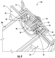
Figure 4 schematically depicts a cross-sectional view of the media sub-assembly ofFigure 1A when a large diameter media roll is being loaded onto the printer. -
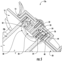
Figure 5 schematically depicts a cross-sectional view of the media sub-assembly ofFigure 1A when a medium diameter media roll is being loaded onto the printer. -
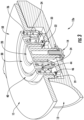
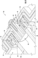
Figure 6 schematically depicts a cross-sectional view of the media sub-assembly ofFigure 1A when a small diameter media roll is being loaded onto the printer. -
Figure 7 schematically depicts a cross-sectional view of the platform and the first hub in accordance with an exemplary embodiment of the present invention. -
Figure 8 schematically depicts a cross-sectional view of the platform and the first hub in accordance with another exemplary embodiment of the present invention. -
Figure 9 schematically depicts a perspective view of another exemplary embodiment of the present invention where the hubs are noncircular in cross-section. - The present invention embraces a multiple size media holder assembly for a printer and a printer employing such a media holder assembly.
- In an exemplary embodiment, as seen in
Figure 1 , the present invention includes a printer (10), a media holder assembly (11), comprised of a pair of opposedly mounted media holder subassemblies (12a & 12b). The distance (28) between the media holder subassemblies (12a & 12b) is sized to accommodate a media roll (not shown). -
Figure 1A shows a magnified view of media sub-assembly (12a). Basic components of the media sub-assembly (12a) include a base (13), a platform (15) secured to the base, and 3 hubs: first hub (20), second hub (30) and third hub (40), each sized to accommodate the inner diameters of three varying sized media rolls (not shown) and each having an exterior surface (not visible in this view) to support three media rolls of varying inner diameters. The base (13) and the platform (15) can be combined in a single part (not shown) or in the alternative, the base and the platform may be composed of multiple parts. -
Figure 2 shows an exploded view of the media sub-assembly (12a) ofFigure 1 . The media sub-assembly (12a) includes a base (13) and platform (15). The platform (15) is secured to the (base). In the Figure the platform (15) and base (13) are shown secured with a fastener (14) which can be a screw and washer as shown, or other fasteners known in the art. In the alternative, the platform (15) and the base (13) can be molded to form a single part. The platform (15) has a flange (50) and has a central cylindrical depression (16). The cylindrical depression (16) has an inner wall (17), a bottom (18), and at least one stop on the inner wall of the cylindrical depression (not visible in this view). The stop, which will be discussed in more detail in conjunction withFigures 4 ,5 ,6 ,7 and8 could be an annular groove, one or more protruding flanges, one or more of recesses, cutouts, or notches on or in the inner wall (17), or the like. Protruding from the center of the cylindrical depression (16) is the first hub (20). The first hub (20) is sized for a first media roll (not shown). The first hub has an exterior surface (23) to support the first media roll. In the Figure, the first hub is depicted as having a circular cross-section, but other cross-sectional shape are contemplated based upon the first hub's (20) exterior surface (23) supporting the first media roll. In the present invention the cross-sectional shapes of the first hub is triangular. The first hub (20) may have any cross-sectional shape which can be encompassed by the inner diameter, usually circular, of the media roll and adequately supports it. It can be seen from the Figure that the height of the first hub (20) extends higher than the flange (50). Other features of the first hub (20) will be described in conjunction with subsequent Figures which show those features. A first spring (24) concentric to the first hub (20) is disposed in the cylindrical depression (16). The second hub (30) is sized for a second media roll (not shown) and has an exterior surface (32) for supporting the second media roll. The second hub (30) may be ring-shaped as shown inFigure 2 , or any shape which will support the second media roll. For example, the second hub (30) may have any cross-sectional geometric shape which fits within the inner diameter, usually circular, of the media roll and around the first hub (20). In the present invention the cross-sectional shapes of the second hub is triangular and has an exterior surface (32) which will support the second media roll. The second hub (30) is concentric to the first hub (20) and has a height less than the height of the first hub (20). The second hub (30) is supported by the first spring (24). For example, the second hub (30) may be profiled to fit over the first spring (24) in the cylindrical depression (16). However, the second hub (30) may be supported by the first spring (24) by a number of other mechanisms or constructions. For example, the second hub (30) may be notched to be supported by the first spring (24). As will be seen in Figures presented hereinafter, the first spring (24) biases the second hub (20) to a height substantially level with that of the first hub (20). A second spring (26) concentric to the first hub (20) and sized to fit around the second hub (30) is also provided. A third hub (40) is provided which is sized for a third media roll (not shown). The third hub (40) is sized to fit around the second hub (30). The third hub (40) has an exterior surface (42) for supporting the third media roll. The third hub (40) may be ring-shaped as shown in the Figure, or any shape which will support the third media roll. For example, the third hub (40) may have any cross-sectional geometric shape which fits within the inner diameter, usually circular, of the third media roll and around the second hub (30). For example the third hub may be triangular in cross-section, having an exterior surface (42) will support the third media roll. Further, the third hub (40) is supported by the second spring (26). For example, and as shown inFigure 2 , the third hub (40) is profiled to fit over the second spring (26). However, other constructions and mechanisms are possible for the third hub (40) to be supported by the second spring as discussed hereinbefore with respect to the second hub (20) and the first spring (24). The second spring (26) biases the third hub to a level substantially equal to that of the first hub (20). It can be seen from the presentFigure 2 that if a media assembly was desired to accommodate only two media rolls, then the third hub and second spring would be unnecessary. However, the present invention also contemplates that more than three media roll sizes could be accommodated by adjusting the sizes of components, including the platform (15), and adding springs and hubs. - When the media sub-assembly (12a) is assembled, the second hub (30) is slidably engaged to the first hub (20). To that purpose, one way to accomplish the slidable engagement, without wishing to be limited, is to provide the second hub (30) with at least one retainer (33) which is pictured as a flange, tab, or protrusion on the inner diameter (31) of the second hub (30). The first hub (20) is correspondingly provided with a stop (not visible in this
Figure 2 ) on the exterior surface (23) of the first hub (20) under or in which the retainer (33) on the second hub (30) is disposed. The stop on the exterior surface (23) of the first hub (20) may be a continuous annular groove for receiving the at least one retainer (33) of the second hub (30). In an alternate embodiment, the stop could be one or more flanges protruding from the exterior surface (21) of the first hub (20). In another embodiment, the at least one stop on the exterior surface (23) of the first hub could be one or more recesses, cutouts, or notches in the exterior surface (23) of the first hub designed to receive the at least one retainer (33) of the second hub (30). The slidable engagement will be discussed in more detail hereinafter. - The third hub (40) and the second hub (30) are in slidable engagement when the media sub-assembly (12a) is fully assembled. The slidable engagement will be discussed in more detail hereinafter in conjunction with
Figures (4 ,5 ,6 ,7 , and8 ). - The outermost hub, in
Figure 2 this being the third hub (40), is slidably engaged to the inner wall (17) of the cylindrical depression (16). One way to accomplish the slidable engagement is shown in the Figure. Without wishing to be limited, the third hub (40) may be provided with at least one retainer (46) which is pictured as a flange, tab, or protrusion on the exterior surface (42) of the third hub (40). The inner wall (17) of the cylindrical depression (16) is correspondingly provided with a stop (not visible in this Figure) under or in which the retainer (46) on the third hub (40) is disposed. The stop on the inner wall (17) of the cylindrical depression (16) may be a continuous annular groove for receiving the at least one retainer (46) of the third hub (40). In another embodiment, the stop could be one or more flanges protruding from the inner wall (17). In another embodiment, the at least one stop on the inner wall (17) could be one or more recesses, cutouts, or notches in the inner wall (17) designed to receive the at least one retainer (46) of the third hub (40). The slidable engagement will be discussed in more detail hereinafter. - Referring now to
Figure 3 , which is a cross-sectional view of the media holder sub-assembly (12a) ofFigure 2 , now fully assembled without a media roll in place. - From the present
Figure 3 , it can be seen as described hereinbefore, that the first spring (24) and the second spring (26) bias the second hub (30) and the third hub (40) respectively to a height level with the height of the first hub (20) and above that of the flange (50). - Exemplary embodiments of mechanisms to accomplish the slidable engagements between components are visible in the current view. In the
Figure 3 , the first hub (20) has a stop (22) on the exterior surface (23). InFigure 3 , the stop (22) is a recess or cutout disposed near the bottom (21) of the first hub (20). However, as discussed hereinbefore, the stop (22) could be one or more tabs or flanges protruding from the exterior surface (23) or notches in the exterior surface (23). The stop (22) may be a continuous annular groove or a series of recesses, cutouts, or notches. The second hub (30) may be provided with at least on retainer (33) on the inner diameter (31). In the presentFigure 3 , the at least one retainer (33) is illustrated as a tab or flange on the inner diameter (31) as discussed hereinbefore. The at least one retainer (33) is disposed in the stop (22) of the first hub (20). As can be seen, the stop (22) limits the biasing of the second hub (30) by the first spring (24). As discussed hereinbefore, but not visible in the previous Figures, the cylindrical depression (16) is provided with at least one stop (19). In the presentFigure 3 , the at least one stop (19) is a recess or cutout in the inner wall (17). The recess may be a continuous annular groove or may be a series of recesses, cutouts, or notches. In another embodiment, the at least one stop may be one or more tabs protruding from the inner wall (17) of the cylindrical depression (16). The third hub (40) is provided with at least one retainer (46), depicted as a tab positioned at the bottom of the exterior surface (42) of the third hub (40) in the presentFigure 3 . The at least one retainer (46) of the third hub (40) engages the stop (19), in this case a recess, on the inner wall (17) of the cylindrical depression (16). The stop (19) limits the biasing of the third hub (40) by the second spring (26). - The second hub (30) and the third hub (40) are slidably engaged to each other. Without wishing to be limited, one way to accomplish this slidable engagement is to provide the exterior surface (32) of the second hub (30) with a stop (34) shown in the present
Figure 3 as a step profile. The third hub (40) may be provided with a retainer (44) on the inner diameter, shown in the present Figure as a step profile. The step profiles, stop (34), and retainer (44), may be continuous or be one or more discrete tabs. When the media sub-assembly (12a) is assembled, the retainer (44) of the third hub (40) is aligned under the stop (34) of the second hub (30). Thus the step (34) on the second hub (30) limits, along with the slidable engagement of the third hub (40) with the stop (19) on the inner wall (17) of the cylindrical depression (16), the movement of the third hub (40) and the biasing of the third hub (40) by the second spring (26). -
Figures 4 ,5 , and6 show cross-sectional views of the media sub-assembly (12a) when media rolls of various diameters are loaded onto the media assembly (11). For example, the media assembly may be designed for media rolls of 2.54 cm (1 inch) inner diameter, 1.905 cm (0.75 inch) inner diameter, and 1.016 cm (0.4 inch) inner diameter, which are standard industry sizes for mobile barcode printers. However, it is to be understood that other media roll sizes can be accommodated. In fact, the media sub-assembly (12a) is not limited to accommodating only 3 media rolls. It is readily apparent to those skilled in the art that by adjusting dimensions and adding hubs, more than 3 sizes of media rolls could be accommodated by the same mechanisms of the present invention. - Referring now to
Figure 4 , a large diameter media roll (29a), for example a 2.54 cm (1 inch) inner diameter media roll, sits on the flange (50) and around the third hub (40). The exterior surface (42) of the third hub (40) supports the media roll (29a). - In
Figure 5 , a medium diameter media roll (29b), for example a 1.905 cm (0.75) inch inner diameter media roll, is shown loaded on the media sub-assembly (12a). As described hereinbefore, the media roll (29b) length is equal to the distance (28) between the two platforms on the media assembly (11). The media roll (29b) is loaded on top of the third hub (40) and is supported around the second hub (30) by the exterior surface (32) of the second hub (30), compressing the second spring (26) such that the third hub (40) descends to substantially the same level as the flange (50). Note also, that third hub (40) retainer (44) is now disengaged from second hub (30) stop (34). - In
Figure 6 , a small diameter media roll (29c), for example a 1.016 cm (0.4 inch) inner diameter media roll, is shown loaded on the media sub-assembly (12a). As described hereinbefore, the media roll (29c) length is equal to the distance (28) between the two platforms on the media assembly (11). The media roll (29c) is mounted on top of the second hub (30) and is supported by the exterior surface (23) of the first hub (20), compressing the first spring (24) such that the second hub (30) descends to substantially the same level as the flange (50). Note here that second hub (30) stop (34) remains in engaged with third hub (40) retainer (44) so that both the second hub (30) and the third hub (40) descend together. Additionally, second hub retainer (33) is disengaged from first hub (20) stop (22) as the media roll is inserted on top of the second hub (30). - As can be seen from
Figures 4 ,5 , and6 , in the present embodiment shown, the stop (22) on the first hub (20) is not continuous around the exterior surface (23) of the first hub (20) as the stop (22) is only visible on one side of the cross-sectional view. InFigure 3 , the stop (22) was visible on both sides of the cutaway. In a like manner, the at least one stop (19) on the inner wall of the cylindrical depression (16) is discontinuous in the presentFigure 6 and not visible on either side of the cutaway. As discussed hereinbefore, the at least one stop (22) of the first hub (20) and the at least one stop (19) on the inner wall (17) of the cylindrical depression (16) may take one of several forms such as an annular groove, a series of recesses, protrusions, cutouts, or notches and the like. - As can be seen from
Figures 4 ,5 , and6 , the slidable engagement between second hub (30) and the third hub (40) allows the third hub (40) enough movement for the second hub's (30) exterior surface (32) to support a media roll sized for the second hub (30) when such a media roll is loaded on the media sub-assemblies. In a like manner, the slidable engagement of the second hub (30) with the first hub (20) provides enough movement of the second hub (30) for the first hub's (20) exterior surface (23) to support a media roll sized for the first hub (20) when such a media roll is loaded on the media sub-assemblies. - The first spring (24) and the second spring (26) in any of the foregoing figures have spring constants. Preferably the spring constants are different, and more preferably, the first spring constant is less than or equal to the second spring constant. As can be seen in
Figure 6 , loading a media roll (29c) to be supported by the exterior surface (23) of the first hub (20), works against the biasing spring force of both the first spring (24) and second spring (26). Advantageously, the first spring (24) constant will be less than the second spring (26) constant so that it is not too difficult to load the media roll (29c) as spring constants are additive in this configuration. InFigure 5 , loading the media roll (29b) only requires pressure against the third hub (40), that is, working against the biasing spring force of the second spring (26). - Referring now to
Figure 7 , depicted is the platform (15) and first hub without the other hubs or springs assembled in order to see certain features. The platform (15) has a cylindrical depression (16) and a flange (50). The first hub (20) protrudes from the cylindrical depression (16) above the flange (50). In the presentFigure 7 , the at least one stop (19a) discussed hereinbefore is shown as one or more recesses on the inner wall (17) of the cylindrical depression (16). The recess could be continuous as in an annular groove, or a series of recesses, cutouts, or notches. Similarly, the at least one stop (22a) on the exterior surface (23) of the first hub (20) is shown as a cutout near the bottom of the first hub (20). - Referring now to
Figure 8 , an alternate stop (22b) pattern for the first hub (20) and the stop (19b) on the inner wall (17) is depicted. The at least one stop (19b) on the inner wall (17) of the cylindrical depression (16) is a protruding tab. The protruding tab stop (19b) could be a continuous step, or a series of tabs on the inner wall (17). The first hub (20) has at least one stop (22b) on the exterior surface (23). In one embodiment, the at least one stop is a continuous tab or series of protruding tabs. - Referring now to
Figure 9 , as discussed herein before, the hubs may be noncircular in cross-section.Figure 9 shows one example. A media holder (212) is comprised of a base (213) and a platform (215) secured to the base. The base and the platform may be a single component or separate components as shown. The platform (215) has a centrally located triangularly-shaped depression (216). The first hub (220), the second hub (230), and the third hub (240) have triangular cross-sectional shapes to fit in the shaped depression (216). The hubs (220, 230, and 240) may have sides which are perpendicular to the platform (215) or, in an alternative embodiment, have sides which taper. Hubs with tapered sides may accommodate media rolls with poor tolerances from the factory. Hubs with tapered sides also provide a convenience when mounting the media rolls on the hubs. As in the exemplary embodiments described hereinbefore, in all other aspects, the media holder (212) has components and functions as described in conjunction with the circular hubs. -
Figure 9 illustrates one option for non-circular hubs, but there are other options in accordance with the present invention, including exemplary embodiments wherein the hubs have different cross-sectional shapes. As long as the hubs are concentric and all the hubs are encompassed by the central depression in the platform, the media holder functions as described hereinbefore in conjunction with the circular hubs and the cylindrical depression.
Claims (13)
- A media holder (212) comprised of:a platform (215) having a flange;a first hub (220) having an exterior surface to support a first media roll; anda second hub (230) having an exterior surface to support a second media roll, the second hub (230) concentric to the first hub (220);characterized in thatthe platform (215) has a triangular shaped depression (216) central to the platform, the triangular shaped depression (216) having an inner wall;the first hub (220) protrudes from the center of the triangular shaped depression (216) and has a height greater than the depth of the triangular shaped depression (216), wherein the first hub (220) has triangular cross section;the media holder (212) further comprises a first spring concentric to the first hub (220) and disposed in the triangular shaped depression (216); andthe second hub (230) is supported by the first spring in the triangular shaped depression (216), the first spring biasing the second hub (230) to a height equal to the height of the first hub (220), the second hub (230) being slidably engaged to the first hub (220), wherein the second hub (230) has triangular cross section.
- The media holder (212) of claim 1, further comprising:a second spring, concentric to and sized to fit around the second hub (230); anda third hub (240) having an exterior surface to support a third media roll, the third hub (240) being concentric to the second hub (230), the third hub (240) being supported by the second spring, the second spring biasing the third hub (240) to a height equal to the height of the first hub (220), the third hub (240) being slidably engaged to the second hub (230).
- The media holder (212) of claim 2, wherein the slidable engagement of the third hub (240) to the second hub (230) allows movement of the third hub (240) from a position of equal height to the height of the first hub (220) to a position lower in height than the height of the first hub (220); and wherein the slidable engagement between the second hub (230) and the first hub (220) allows movement of the second hub (230) from a height equal to the height of the first hub (220) to a position lower in height than the height of the first hub (220).
- The media holder (212) of claim 3, wherein, when a media roll sized to be supported by the exterior surface of the second hub (230) is supported by the second hub (230), pressure is applied to the third hub (240) of the media holder, compressing the second spring and sliding the third hub (240) towards the bottom of the triangular shaped depression (216).
- The media holder (212) of claim 1, wherein, when a media roll sized to be supported by the exterior surface of the first hub (220) is supported by the first hub (220), pressure is applied to the second hub (230) of the media holder (212), compressing the first spring and sliding the second hub (230) towards the bottom of the triangular depression (216); and
wherein the second spring is compressed and the third hub (240) slides towards the bottom of the triangular shaped depression (216) when pressure is applied to the second hub (230), based upon the slidable engagement of the second hub (230) to the third hub (240). - A printer (10) having a pair of media holder sub-assemblies, each sub-assembly (12a, 12b) comprising:the media holder of claim 1;a second spring, concentric to the first hub (220) and sized to fit around the second hub (230); anda third hub (240) sized to support a third media roll, the third hub (240) sized to fit around the second hub (230) and within the inner wall of the triangular depression (216), the third hub (230) being supported by the second spring, the second spring biasing the third hub (240) to a height equal to the height of the first hub (220), the third hub (240) being slidably engaged to the second hub (230) and to the inner wall of the triangular depression (216), wherein the third hub (240) has a triangular cross-section.
- The printer (10) of claim 6, wherein the slidable engagement of the second hub (230) to the first hub (220) allows movement of the second hub (230) from a height equal to the height of the first hub (220) to a position lower in height than the height of the first hub (220); and wherein the slidable engagement between the third hub (240) and the second hub (230) and between the third hub (240) and the inner wall of the triangular depression (216) allows movement of the third hub (240) from a height equal to the height of the first hub (220) to a position lower in height than the height of the first hub (220).
- The printer (10) of claim 7, wherein the triangular depression (216) has a bottom, the triangular depression (216) having at least one stop on the inner wall, the stop being a first predetermined distance from the bottom of the inner wall; wherein the first hub (220) has an exterior surface and a bottom, the first hub (220) having at least one stop on the exterior surface of the first hub (220), the stop being a second predetermined distance from the bottom of the first hub (220); wherein the second hub (230) has a bottom, an inner surface, and an exterior surface, the second hub (230) having at least one retainer at the bottom of the inner surface and disposed in a position below the at least one stop on the first hub (220), the second hub (230) having at least one stop on the exterior surface; wherein the third hub (240) has an inner surface and an exterior surface, the third hub (240) having at least one retainer on the exterior surface of the third hub (240) disposed in a position below the at least one stop in on the inner wall of the triangular depression (216), the third hub (240) having at least one retainer on the inner surface of the third hub (240), the retainer being aligned below the at least one stop on the exterior surface of the second hub (230).
- The printer (10) of claim 8, wherein the first predetermined distance and/or the second predetermined distance is equal to the difference between the height of the first hub (220) and the depth of the triangular depression (216).
- The printer (10) of claim 6, wherein the media holder sub-assemblies (12a, 12b) are configured to slidably adjust based upon a media roll being loaded on the media holder (212); the distance between the platforms (215) on the opposedly mounted media holder sub-assemblies (12a, 12b) being equal to the length of the media roll.
- The printer (10) of claim 10, wherein when a media roll sized to be supported by the second hub (230) is mounted in the media holder, pressure is applied to the third hub (240) on each of the media holder sub-assemblies (12a, 12b), compressing the second spring and sliding the third hub (240) towards the bottom of the triangular depression (216).
- The printer (10) of claim 10, wherein when a media roll sized for the first hub (220) is being mounted in the media holder, pressure is applied to the second hub (230) on each of the media holder sub-assemblies (12a, 12b), compressing the first spring and sliding the second hub (230) towards the bottom of the triangular depression (216);
preferably wherein the second spring is compressed and the third hub (240) slides towards the bottom of the triangular depression (216) when pressure is applied to the second hub (230), based upon the slidable engagement of the second hub (230) to the third hub (240). - The printer (10) of claim 6, wherein the first spring has an uncompressed height greater than the height of the second hub (230); and the second spring has an uncompressed height greater than the height of the third hub (240).
Priority Applications (2)
| Application Number | Priority Date | Filing Date | Title |
|---|---|---|---|
| EP23150760.9A EP4194216B1 (en) | 2017-05-08 | 2017-05-08 | Multiple size media holder assembly for a mobile printer |
| EP25176212.6A EP4578807A3 (en) | 2017-05-08 | 2017-05-08 | Multiple size media holder assembly for a mobile printer |
Applications Claiming Priority (3)
| Application Number | Priority Date | Filing Date | Title |
|---|---|---|---|
| PCT/CN2017/083394 WO2018205074A1 (en) | 2017-05-08 | 2017-05-08 | Multiple size media holder assembly for a mobile printer |
| EP17908874.5A EP3621815B1 (en) | 2017-05-08 | 2017-05-08 | Multiple size media holder assembly for a mobile printer |
| EP23150760.9A EP4194216B1 (en) | 2017-05-08 | 2017-05-08 | Multiple size media holder assembly for a mobile printer |
Related Parent Applications (2)
| Application Number | Title | Priority Date | Filing Date |
|---|---|---|---|
| EP17908874.5A Division EP3621815B1 (en) | 2017-05-08 | 2017-05-08 | Multiple size media holder assembly for a mobile printer |
| EP17908874.5A Division-Into EP3621815B1 (en) | 2017-05-08 | 2017-05-08 | Multiple size media holder assembly for a mobile printer |
Related Child Applications (2)
| Application Number | Title | Priority Date | Filing Date |
|---|---|---|---|
| EP25176212.6A Division-Into EP4578807A3 (en) | 2017-05-08 | 2017-05-08 | Multiple size media holder assembly for a mobile printer |
| EP25176212.6A Division EP4578807A3 (en) | 2017-05-08 | 2017-05-08 | Multiple size media holder assembly for a mobile printer |
Publications (2)
| Publication Number | Publication Date |
|---|---|
| EP4194216A1 EP4194216A1 (en) | 2023-06-14 |
| EP4194216B1 true EP4194216B1 (en) | 2025-07-09 |
Family
ID=64104369
Family Applications (3)
| Application Number | Title | Priority Date | Filing Date |
|---|---|---|---|
| EP17908874.5A Active EP3621815B1 (en) | 2017-05-08 | 2017-05-08 | Multiple size media holder assembly for a mobile printer |
| EP25176212.6A Pending EP4578807A3 (en) | 2017-05-08 | 2017-05-08 | Multiple size media holder assembly for a mobile printer |
| EP23150760.9A Active EP4194216B1 (en) | 2017-05-08 | 2017-05-08 | Multiple size media holder assembly for a mobile printer |
Family Applications Before (2)
| Application Number | Title | Priority Date | Filing Date |
|---|---|---|---|
| EP17908874.5A Active EP3621815B1 (en) | 2017-05-08 | 2017-05-08 | Multiple size media holder assembly for a mobile printer |
| EP25176212.6A Pending EP4578807A3 (en) | 2017-05-08 | 2017-05-08 | Multiple size media holder assembly for a mobile printer |
Country Status (4)
| Country | Link |
|---|---|
| US (1) | US10913298B2 (en) |
| EP (3) | EP3621815B1 (en) |
| CN (1) | CN110869219B (en) |
| WO (1) | WO2018205074A1 (en) |
Families Citing this family (1)
| Publication number | Priority date | Publication date | Assignee | Title |
|---|---|---|---|---|
| JP2025059159A (en) * | 2023-09-29 | 2025-04-10 | ブラザー工業株式会社 | Printer |
Family Cites Families (17)
| Publication number | Priority date | Publication date | Assignee | Title |
|---|---|---|---|---|
| DE69705353T2 (en) | 1996-04-29 | 2002-04-25 | Hewlett-Packard Co.(A Delaware Corporation), Palo Alto | Adjustable spindle drive arrangement for media conveyance by means of rollers in an ink jet printer / plotter |
| US6130699A (en) * | 1997-07-03 | 2000-10-10 | Datamax Corporation | Thermal ink printer with media supply |
| JP3758118B2 (en) | 1998-09-01 | 2006-03-22 | 東芝テック株式会社 | Roll paper holding device |
| JP4401534B2 (en) | 1999-08-26 | 2010-01-20 | 東北リコー株式会社 | Master base paper roll and master base paper roll holding device |
| JP3928705B2 (en) | 2002-03-20 | 2007-06-13 | セイコーエプソン株式会社 | Roll recording medium holding means and recording apparatus |
| JP2007090707A (en) | 2005-09-29 | 2007-04-12 | Seiko I Infotech Inc | Roll body holding device, recording device, and roll body holding method |
| JP5158354B2 (en) | 2008-03-10 | 2013-03-06 | セイコーエプソン株式会社 | Rolled recording material conveying apparatus and recording apparatus |
| JP5665353B2 (en) | 2010-04-23 | 2015-02-04 | キヤノン株式会社 | SUPPORT DEVICE, PRINTING DEVICE, SUPPORT METHOD, AND LOADING METHOD |
| US9004390B2 (en) * | 2010-08-03 | 2015-04-14 | Ricoh Company, Ltd. | Roll medium holding unit, roll sheet feeder, and image forming apparatus |
| US8770508B2 (en) | 2010-10-15 | 2014-07-08 | Seiko Epson Corporation | Recording apparatus and roll paper lifting device |
| JP5846361B2 (en) | 2011-08-29 | 2016-01-20 | セイコーエプソン株式会社 | Roll medium feeding device and recording device |
| JP5114807B1 (en) | 2011-10-04 | 2013-01-09 | 株式会社新盛インダストリーズ | printer |
| JP2014114091A (en) | 2012-12-07 | 2014-06-26 | Seiko Epson Corp | Roll sheet support mechanism and printer |
| US9616516B2 (en) | 2013-07-11 | 2017-04-11 | Illinois Tool Works Inc. | Indexing drive roll carrier system and method |
| JP6299280B2 (en) | 2014-02-28 | 2018-03-28 | ブラザー工業株式会社 | Printing device |
| CN106414093B (en) | 2014-06-05 | 2019-07-23 | 惠普发展公司有限责任合伙企业 | Media Roll Holder |
| JP6357080B2 (en) | 2014-11-11 | 2018-07-11 | 株式会社沖データ | Rolled medium support mechanism, medium conveying apparatus, and image forming apparatus |
-
2017
- 2017-05-08 WO PCT/CN2017/083394 patent/WO2018205074A1/en not_active Ceased
- 2017-05-08 EP EP17908874.5A patent/EP3621815B1/en active Active
- 2017-05-08 EP EP25176212.6A patent/EP4578807A3/en active Pending
- 2017-05-08 CN CN201780090556.6A patent/CN110869219B/en active Active
- 2017-05-08 US US16/611,550 patent/US10913298B2/en active Active
- 2017-05-08 EP EP23150760.9A patent/EP4194216B1/en active Active
Also Published As
| Publication number | Publication date |
|---|---|
| WO2018205074A1 (en) | 2018-11-15 |
| EP4194216A1 (en) | 2023-06-14 |
| US10913298B2 (en) | 2021-02-09 |
| EP3621815A1 (en) | 2020-03-18 |
| EP3621815B1 (en) | 2023-02-22 |
| CN110869219A (en) | 2020-03-06 |
| EP4578807A3 (en) | 2025-09-10 |
| US20200223239A1 (en) | 2020-07-16 |
| CN110869219B (en) | 2021-07-09 |
| EP3621815A4 (en) | 2020-12-09 |
| EP4578807A2 (en) | 2025-07-02 |
Similar Documents
| Publication | Publication Date | Title |
|---|---|---|
| US8752248B2 (en) | Hinge device including pressure contact surfaces | |
| EP3366424B1 (en) | Quick detachable and adjustable magnetic seat for sleeve | |
| US20180001794A1 (en) | Pumping apparatus for vehicle seat | |
| US20060070221A1 (en) | Joint press set | |
| EP3621815B1 (en) | Multiple size media holder assembly for a mobile printer | |
| US20130292527A1 (en) | Vertically movable stand for display device | |
| GB2048423A (en) | Clutch release bearing assembly procided with a self-centring mechanism | |
| KR102364025B1 (en) | Chair-Integrated Ttable With Aautomatic Shock Absorber Attached | |
| US7070246B2 (en) | Wheel device with quick-releasing mechanism | |
| US20170138415A1 (en) | Rotation transmission device | |
| EP2671238B1 (en) | Control device | |
| US11371572B2 (en) | Disc brake for vehicles, in particular for commercial vehicles | |
| EP2672128A1 (en) | Locking device for pipe member | |
| CN112824689B (en) | Nut assembly and electronic expansion valve | |
| JP6682416B2 (en) | One way clutch | |
| US20020110398A1 (en) | Carriage assembly of printer employing movable print head | |
| EP1189227B1 (en) | Optical disk | |
| CN213054643U (en) | Mounting tool of valve seat | |
| JP6388565B2 (en) | Torque limiter device | |
| WO1992000470A1 (en) | Torsional vibration damper | |
| EP1703071B1 (en) | Winding mechanism for a roller screen and mounting means | |
| CN107673013B (en) | Goods shelf and unmanned carrying system with same | |
| EP4360719A1 (en) | Dumbbell with quick release structure | |
| CN218806507U (en) | Unmanned aerial vehicle and undercarriage subassembly thereof | |
| EP2495486B1 (en) | Rotatable coupling mechanism |
Legal Events
| Date | Code | Title | Description |
|---|---|---|---|
| PUAI | Public reference made under article 153(3) epc to a published international application that has entered the european phase |
Free format text: ORIGINAL CODE: 0009012 |
|
| STAA | Information on the status of an ep patent application or granted ep patent |
Free format text: STATUS: THE APPLICATION HAS BEEN PUBLISHED |
|
| AC | Divisional application: reference to earlier application |
Ref document number: 3621815 Country of ref document: EP Kind code of ref document: P |
|
| AK | Designated contracting states |
Kind code of ref document: A1 Designated state(s): AL AT BE BG CH CY CZ DE DK EE ES FI FR GB GR HR HU IE IS IT LI LT LU LV MC MK MT NL NO PL PT RO RS SE SI SK SM TR |
|
| STAA | Information on the status of an ep patent application or granted ep patent |
Free format text: STATUS: REQUEST FOR EXAMINATION WAS MADE |
|
| 17P | Request for examination filed |
Effective date: 20231207 |
|
| RBV | Designated contracting states (corrected) |
Designated state(s): AL AT BE BG CH CY CZ DE DK EE ES FI FR GB GR HR HU IE IS IT LI LT LU LV MC MK MT NL NO PL PT RO RS SE SI SK SM TR |
|
| GRAP | Despatch of communication of intention to grant a patent |
Free format text: ORIGINAL CODE: EPIDOSNIGR1 |
|
| STAA | Information on the status of an ep patent application or granted ep patent |
Free format text: STATUS: GRANT OF PATENT IS INTENDED |
|
| INTG | Intention to grant announced |
Effective date: 20250214 |
|
| GRAS | Grant fee paid |
Free format text: ORIGINAL CODE: EPIDOSNIGR3 |
|
| GRAA | (expected) grant |
Free format text: ORIGINAL CODE: 0009210 |
|
| STAA | Information on the status of an ep patent application or granted ep patent |
Free format text: STATUS: THE PATENT HAS BEEN GRANTED |
|
| AC | Divisional application: reference to earlier application |
Ref document number: 3621815 Country of ref document: EP Kind code of ref document: P |
|
| AK | Designated contracting states |
Kind code of ref document: B1 Designated state(s): AL AT BE BG CH CY CZ DE DK EE ES FI FR GB GR HR HU IE IS IT LI LT LU LV MC MK MT NL NO PL PT RO RS SE SI SK SM TR |
|
| REG | Reference to a national code |
Ref country code: GB Ref legal event code: FG4D |
|
| REG | Reference to a national code |
Ref country code: CH Ref legal event code: EP |
|
| REG | Reference to a national code |
Ref country code: IE Ref legal event code: FG4D |
|
| REG | Reference to a national code |
Ref country code: DE Ref legal event code: R096 Ref document number: 602017090554 Country of ref document: DE |
|
| REG | Reference to a national code |
Ref country code: NL Ref legal event code: MP Effective date: 20250709 |
|
| PG25 | Lapsed in a contracting state [announced via postgrant information from national office to epo] |
Ref country code: PT Free format text: LAPSE BECAUSE OF FAILURE TO SUBMIT A TRANSLATION OF THE DESCRIPTION OR TO PAY THE FEE WITHIN THE PRESCRIBED TIME-LIMIT Effective date: 20251110 |
|
| PG25 | Lapsed in a contracting state [announced via postgrant information from national office to epo] |
Ref country code: NL Free format text: LAPSE BECAUSE OF FAILURE TO SUBMIT A TRANSLATION OF THE DESCRIPTION OR TO PAY THE FEE WITHIN THE PRESCRIBED TIME-LIMIT Effective date: 20250709 |
|
| REG | Reference to a national code |
Ref country code: AT Ref legal event code: MK05 Ref document number: 1811526 Country of ref document: AT Kind code of ref document: T Effective date: 20250709 |
|
| PG25 | Lapsed in a contracting state [announced via postgrant information from national office to epo] |
Ref country code: IS Free format text: LAPSE BECAUSE OF FAILURE TO SUBMIT A TRANSLATION OF THE DESCRIPTION OR TO PAY THE FEE WITHIN THE PRESCRIBED TIME-LIMIT Effective date: 20251109 |
|
| PG25 | Lapsed in a contracting state [announced via postgrant information from national office to epo] |
Ref country code: NO Free format text: LAPSE BECAUSE OF FAILURE TO SUBMIT A TRANSLATION OF THE DESCRIPTION OR TO PAY THE FEE WITHIN THE PRESCRIBED TIME-LIMIT Effective date: 20251009 |
|
| REG | Reference to a national code |
Ref country code: LT Ref legal event code: MG9D |
|
| PG25 | Lapsed in a contracting state [announced via postgrant information from national office to epo] |
Ref country code: AT Free format text: LAPSE BECAUSE OF FAILURE TO SUBMIT A TRANSLATION OF THE DESCRIPTION OR TO PAY THE FEE WITHIN THE PRESCRIBED TIME-LIMIT Effective date: 20250709 |
|
| PG25 | Lapsed in a contracting state [announced via postgrant information from national office to epo] |
Ref country code: FI Free format text: LAPSE BECAUSE OF FAILURE TO SUBMIT A TRANSLATION OF THE DESCRIPTION OR TO PAY THE FEE WITHIN THE PRESCRIBED TIME-LIMIT Effective date: 20250709 |
|
| PG25 | Lapsed in a contracting state [announced via postgrant information from national office to epo] |
Ref country code: HR Free format text: LAPSE BECAUSE OF FAILURE TO SUBMIT A TRANSLATION OF THE DESCRIPTION OR TO PAY THE FEE WITHIN THE PRESCRIBED TIME-LIMIT Effective date: 20250709 |
|
| PG25 | Lapsed in a contracting state [announced via postgrant information from national office to epo] |
Ref country code: GR Free format text: LAPSE BECAUSE OF FAILURE TO SUBMIT A TRANSLATION OF THE DESCRIPTION OR TO PAY THE FEE WITHIN THE PRESCRIBED TIME-LIMIT Effective date: 20251010 |
|
| PG25 | Lapsed in a contracting state [announced via postgrant information from national office to epo] |
Ref country code: SE Free format text: LAPSE BECAUSE OF FAILURE TO SUBMIT A TRANSLATION OF THE DESCRIPTION OR TO PAY THE FEE WITHIN THE PRESCRIBED TIME-LIMIT Effective date: 20250709 |
|
| PG25 | Lapsed in a contracting state [announced via postgrant information from national office to epo] |
Ref country code: LV Free format text: LAPSE BECAUSE OF FAILURE TO SUBMIT A TRANSLATION OF THE DESCRIPTION OR TO PAY THE FEE WITHIN THE PRESCRIBED TIME-LIMIT Effective date: 20250709 |
|
| PG25 | Lapsed in a contracting state [announced via postgrant information from national office to epo] |
Ref country code: PL Free format text: LAPSE BECAUSE OF FAILURE TO SUBMIT A TRANSLATION OF THE DESCRIPTION OR TO PAY THE FEE WITHIN THE PRESCRIBED TIME-LIMIT Effective date: 20250709 Ref country code: BG Free format text: LAPSE BECAUSE OF FAILURE TO SUBMIT A TRANSLATION OF THE DESCRIPTION OR TO PAY THE FEE WITHIN THE PRESCRIBED TIME-LIMIT Effective date: 20250709 |
|
| PG25 | Lapsed in a contracting state [announced via postgrant information from national office to epo] |
Ref country code: RS Free format text: LAPSE BECAUSE OF FAILURE TO SUBMIT A TRANSLATION OF THE DESCRIPTION OR TO PAY THE FEE WITHIN THE PRESCRIBED TIME-LIMIT Effective date: 20251009 |
|
| PG25 | Lapsed in a contracting state [announced via postgrant information from national office to epo] |
Ref country code: ES Free format text: LAPSE BECAUSE OF FAILURE TO SUBMIT A TRANSLATION OF THE DESCRIPTION OR TO PAY THE FEE WITHIN THE PRESCRIBED TIME-LIMIT Effective date: 20250709 |
|
| PG25 | Lapsed in a contracting state [announced via postgrant information from national office to epo] |
Ref country code: SM Free format text: LAPSE BECAUSE OF FAILURE TO SUBMIT A TRANSLATION OF THE DESCRIPTION OR TO PAY THE FEE WITHIN THE PRESCRIBED TIME-LIMIT Effective date: 20250709 |
|
| PG25 | Lapsed in a contracting state [announced via postgrant information from national office to epo] |
Ref country code: DK Free format text: LAPSE BECAUSE OF FAILURE TO SUBMIT A TRANSLATION OF THE DESCRIPTION OR TO PAY THE FEE WITHIN THE PRESCRIBED TIME-LIMIT Effective date: 20250709 |
|
| PG25 | Lapsed in a contracting state [announced via postgrant information from national office to epo] |
Ref country code: IT Free format text: LAPSE BECAUSE OF FAILURE TO SUBMIT A TRANSLATION OF THE DESCRIPTION OR TO PAY THE FEE WITHIN THE PRESCRIBED TIME-LIMIT Effective date: 20250709 |
|
| PG25 | Lapsed in a contracting state [announced via postgrant information from national office to epo] |
Ref country code: CZ Free format text: LAPSE BECAUSE OF FAILURE TO SUBMIT A TRANSLATION OF THE DESCRIPTION OR TO PAY THE FEE WITHIN THE PRESCRIBED TIME-LIMIT Effective date: 20250709 |
|
| PG25 | Lapsed in a contracting state [announced via postgrant information from national office to epo] |
Ref country code: SK Free format text: LAPSE BECAUSE OF FAILURE TO SUBMIT A TRANSLATION OF THE DESCRIPTION OR TO PAY THE FEE WITHIN THE PRESCRIBED TIME-LIMIT Effective date: 20250709 Ref country code: EE Free format text: LAPSE BECAUSE OF FAILURE TO SUBMIT A TRANSLATION OF THE DESCRIPTION OR TO PAY THE FEE WITHIN THE PRESCRIBED TIME-LIMIT Effective date: 20250709 |
|
| PLBE | No opposition filed within time limit |
Free format text: ORIGINAL CODE: 0009261 |
|
| STAA | Information on the status of an ep patent application or granted ep patent |
Free format text: STATUS: NO OPPOSITION FILED WITHIN TIME LIMIT |