EP4194176A1 - Pouch curling prevention device - Google Patents
Pouch curling prevention device Download PDFInfo
- Publication number
- EP4194176A1 EP4194176A1 EP22838033.3A EP22838033A EP4194176A1 EP 4194176 A1 EP4194176 A1 EP 4194176A1 EP 22838033 A EP22838033 A EP 22838033A EP 4194176 A1 EP4194176 A1 EP 4194176A1
- Authority
- EP
- European Patent Office
- Prior art keywords
- pouch
- upper roller
- roller
- lower roller
- prevention apparatus
- Prior art date
- Legal status (The legal status is an assumption and is not a legal conclusion. Google has not performed a legal analysis and makes no representation as to the accuracy of the status listed.)
- Granted
Links
Images


Classifications
-
- B—PERFORMING OPERATIONS; TRANSPORTING
- B29—WORKING OF PLASTICS; WORKING OF SUBSTANCES IN A PLASTIC STATE IN GENERAL
- B29C—SHAPING OR JOINING OF PLASTICS; SHAPING OF MATERIAL IN A PLASTIC STATE, NOT OTHERWISE PROVIDED FOR; AFTER-TREATMENT OF THE SHAPED PRODUCTS, e.g. REPAIRING
- B29C51/00—Shaping by thermoforming, i.e. shaping sheets or sheet like preforms after heating, e.g. shaping sheets in matched moulds or by deep-drawing; Apparatus therefor
- B29C51/26—Component parts, details or accessories; Auxiliary operations
- B29C51/261—Handling means, e.g. transfer means, feeding means
-
- B—PERFORMING OPERATIONS; TRANSPORTING
- B29—WORKING OF PLASTICS; WORKING OF SUBSTANCES IN A PLASTIC STATE IN GENERAL
- B29C—SHAPING OR JOINING OF PLASTICS; SHAPING OF MATERIAL IN A PLASTIC STATE, NOT OTHERWISE PROVIDED FOR; AFTER-TREATMENT OF THE SHAPED PRODUCTS, e.g. REPAIRING
- B29C51/00—Shaping by thermoforming, i.e. shaping sheets or sheet like preforms after heating, e.g. shaping sheets in matched moulds or by deep-drawing; Apparatus therefor
- B29C51/26—Component parts, details or accessories; Auxiliary operations
-
- B—PERFORMING OPERATIONS; TRANSPORTING
- B29—WORKING OF PLASTICS; WORKING OF SUBSTANCES IN A PLASTIC STATE IN GENERAL
- B29C—SHAPING OR JOINING OF PLASTICS; SHAPING OF MATERIAL IN A PLASTIC STATE, NOT OTHERWISE PROVIDED FOR; AFTER-TREATMENT OF THE SHAPED PRODUCTS, e.g. REPAIRING
- B29C51/00—Shaping by thermoforming, i.e. shaping sheets or sheet like preforms after heating, e.g. shaping sheets in matched moulds or by deep-drawing; Apparatus therefor
- B29C51/08—Deep drawing or matched-mould forming, i.e. using mechanical means only
-
- B—PERFORMING OPERATIONS; TRANSPORTING
- B29—WORKING OF PLASTICS; WORKING OF SUBSTANCES IN A PLASTIC STATE IN GENERAL
- B29C—SHAPING OR JOINING OF PLASTICS; SHAPING OF MATERIAL IN A PLASTIC STATE, NOT OTHERWISE PROVIDED FOR; AFTER-TREATMENT OF THE SHAPED PRODUCTS, e.g. REPAIRING
- B29C51/00—Shaping by thermoforming, i.e. shaping sheets or sheet like preforms after heating, e.g. shaping sheets in matched moulds or by deep-drawing; Apparatus therefor
- B29C51/08—Deep drawing or matched-mould forming, i.e. using mechanical means only
- B29C51/082—Deep drawing or matched-mould forming, i.e. using mechanical means only by shaping between complementary mould parts
-
- B—PERFORMING OPERATIONS; TRANSPORTING
- B29—WORKING OF PLASTICS; WORKING OF SUBSTANCES IN A PLASTIC STATE IN GENERAL
- B29C—SHAPING OR JOINING OF PLASTICS; SHAPING OF MATERIAL IN A PLASTIC STATE, NOT OTHERWISE PROVIDED FOR; AFTER-TREATMENT OF THE SHAPED PRODUCTS, e.g. REPAIRING
- B29C51/00—Shaping by thermoforming, i.e. shaping sheets or sheet like preforms after heating, e.g. shaping sheets in matched moulds or by deep-drawing; Apparatus therefor
- B29C51/14—Shaping by thermoforming, i.e. shaping sheets or sheet like preforms after heating, e.g. shaping sheets in matched moulds or by deep-drawing; Apparatus therefor using multilayered preforms or sheets
-
- B—PERFORMING OPERATIONS; TRANSPORTING
- B29—WORKING OF PLASTICS; WORKING OF SUBSTANCES IN A PLASTIC STATE IN GENERAL
- B29C—SHAPING OR JOINING OF PLASTICS; SHAPING OF MATERIAL IN A PLASTIC STATE, NOT OTHERWISE PROVIDED FOR; AFTER-TREATMENT OF THE SHAPED PRODUCTS, e.g. REPAIRING
- B29C51/00—Shaping by thermoforming, i.e. shaping sheets or sheet like preforms after heating, e.g. shaping sheets in matched moulds or by deep-drawing; Apparatus therefor
- B29C51/26—Component parts, details or accessories; Auxiliary operations
- B29C51/261—Handling means, e.g. transfer means, feeding means
- B29C51/262—Clamping means for the sheets, e.g. clamping frames
-
- B—PERFORMING OPERATIONS; TRANSPORTING
- B29—WORKING OF PLASTICS; WORKING OF SUBSTANCES IN A PLASTIC STATE IN GENERAL
- B29C—SHAPING OR JOINING OF PLASTICS; SHAPING OF MATERIAL IN A PLASTIC STATE, NOT OTHERWISE PROVIDED FOR; AFTER-TREATMENT OF THE SHAPED PRODUCTS, e.g. REPAIRING
- B29C51/00—Shaping by thermoforming, i.e. shaping sheets or sheet like preforms after heating, e.g. shaping sheets in matched moulds or by deep-drawing; Apparatus therefor
- B29C51/26—Component parts, details or accessories; Auxiliary operations
- B29C51/265—Auxiliary operations during the thermoforming operation
-
- H—ELECTRICITY
- H01—ELECTRIC ELEMENTS
- H01M—PROCESSES OR MEANS, e.g. BATTERIES, FOR THE DIRECT CONVERSION OF CHEMICAL ENERGY INTO ELECTRICAL ENERGY
- H01M10/00—Secondary cells; Manufacture thereof
- H01M10/04—Construction or manufacture in general
- H01M10/0404—Machines for assembling batteries
-
- H—ELECTRICITY
- H01—ELECTRIC ELEMENTS
- H01M—PROCESSES OR MEANS, e.g. BATTERIES, FOR THE DIRECT CONVERSION OF CHEMICAL ENERGY INTO ELECTRICAL ENERGY
- H01M50/00—Constructional details or processes of manufacture of the non-active parts of electrochemical cells other than fuel cells, e.g. hybrid cells
- H01M50/10—Primary casings; Jackets or wrappings
- H01M50/102—Primary casings; Jackets or wrappings characterised by their shape or physical structure
- H01M50/105—Pouches or flexible bags
-
- B—PERFORMING OPERATIONS; TRANSPORTING
- B29—WORKING OF PLASTICS; WORKING OF SUBSTANCES IN A PLASTIC STATE IN GENERAL
- B29C—SHAPING OR JOINING OF PLASTICS; SHAPING OF MATERIAL IN A PLASTIC STATE, NOT OTHERWISE PROVIDED FOR; AFTER-TREATMENT OF THE SHAPED PRODUCTS, e.g. REPAIRING
- B29C51/00—Shaping by thermoforming, i.e. shaping sheets or sheet like preforms after heating, e.g. shaping sheets in matched moulds or by deep-drawing; Apparatus therefor
- B29C51/04—Combined thermoforming and prestretching, e.g. biaxial stretching
-
- B—PERFORMING OPERATIONS; TRANSPORTING
- B29—WORKING OF PLASTICS; WORKING OF SUBSTANCES IN A PLASTIC STATE IN GENERAL
- B29L—INDEXING SCHEME ASSOCIATED WITH SUBCLASS B29C, RELATING TO PARTICULAR ARTICLES
- B29L2031/00—Other particular articles
-
- B—PERFORMING OPERATIONS; TRANSPORTING
- B29—WORKING OF PLASTICS; WORKING OF SUBSTANCES IN A PLASTIC STATE IN GENERAL
- B29L—INDEXING SCHEME ASSOCIATED WITH SUBCLASS B29C, RELATING TO PARTICULAR ARTICLES
- B29L2031/00—Other particular articles
- B29L2031/34—Electrical apparatus, e.g. sparking plugs or parts thereof
- B29L2031/3468—Batteries, accumulators or fuel cells
-
- B—PERFORMING OPERATIONS; TRANSPORTING
- B29—WORKING OF PLASTICS; WORKING OF SUBSTANCES IN A PLASTIC STATE IN GENERAL
- B29L—INDEXING SCHEME ASSOCIATED WITH SUBCLASS B29C, RELATING TO PARTICULAR ARTICLES
- B29L2031/00—Other particular articles
- B29L2031/712—Containers; Packaging elements or accessories, Packages
- B29L2031/7146—Battery-cases
-
- Y—GENERAL TAGGING OF NEW TECHNOLOGICAL DEVELOPMENTS; GENERAL TAGGING OF CROSS-SECTIONAL TECHNOLOGIES SPANNING OVER SEVERAL SECTIONS OF THE IPC; TECHNICAL SUBJECTS COVERED BY FORMER USPC CROSS-REFERENCE ART COLLECTIONS [XRACs] AND DIGESTS
- Y02—TECHNOLOGIES OR APPLICATIONS FOR MITIGATION OR ADAPTATION AGAINST CLIMATE CHANGE
- Y02E—REDUCTION OF GREENHOUSE GAS [GHG] EMISSIONS, RELATED TO ENERGY GENERATION, TRANSMISSION OR DISTRIBUTION
- Y02E60/00—Enabling technologies; Technologies with a potential or indirect contribution to GHG emissions mitigation
- Y02E60/10—Energy storage using batteries
Definitions
- the present invention relates to a battery module assembly apparatus with improved productivity and an assembly method using the same. More particularly, the present invention relates to a battery module assembly apparatus including two or more bonding units and capable of individually supplying a battery module to each bonding unit to electrically connect a battery cell and a busbar to each other and an assembly method using the same.
- the lithium secondary battery includes an electrode assembly, configured such that a positive electrode sheet having a positive electrode active material applied thereto and a negative electrode sheet having a negative electrode active material applied thereto are disposed in the state in which a separator is interposed therebetween, and a battery case configured to receive the electrode assembly together with an electrolytic solution in a sealed state.
- the lithium secondary battery may generally be classified as a can-shaped secondary battery having an electrode assembly mounted in a metal can or a pouch-shaped secondary battery having an electrode assembly mounted in a pouch made of an aluminum laminate sheet.
- a process of manufacturing the pouch-shaped secondary battery in order to reduce a dead space in a battery cell while stably mounting and fixing the electrode assembly, which has a predetermined volume, in the battery case, a process of forming an electrode assembly receiving portion in the laminate sheet is generally performed using a deep drawing apparatus.
- FIG. 1 is an exploded perspective view schematically showing the construction of a general pouch-shaped secondary battery.
- the pouch-shaped secondary battery which is a single cup type pouch-shaped secondary battery, includes a pouch case 3 made of an aluminum laminate sheet and a cell assembly 1 received in the pouch case 3, the cell assembly being configured such that a plurality of electrochemical cells, each of which includes a positive electrode, a separator, and a negative electrode, is stacked.
- the pouch case 3 is a single cup type pouch case configured such that connection is achieved at one edge thereof.
- the pouch case 3 includes an upper pouch film 3 (a) and a lower pouch film 3 (b) .
- a cup portion 2 configured to allow the cell assembly 1 to be seated therein is formed in the lower pouch film 3(b).
- the cup portion 2, which has a shape corresponding to the shape of the cell assembly 1, is formed in the lower pouch film 3(b) through a forming process, wherein the depth h of the cup portion is set depending on the thickness of the cell assembly 1.
- FIG. 2 is a process view showing a forming process in which a pouch film forming apparatus 10 forms a receiving portion in a pouch film 30.
- (a) of FIG. 2 is a forming process plan view
- (b) of FIG. 2 is a forming process side view.
- the pouch film forming apparatus 10 includes a punch 11, a stripper 12, and a die 13.
- the die 13 is provided with a seating recess (not shown) having a shape corresponding to the shape of a desired pouch case when the pouch case is formed using the pouch film 30.
- the depth of the seating recess corresponds to the depth of a receiving portion to be formed in the desired pouch case.
- the punch 11 applies pressure to the pouch film 30 disposed on the die 13. That is, the punch presses the pouch film to form the pouch case.
- Patent Document 1 which relates to a process of forming an electrode assembly receiving portion using a deep drawing apparatus capable of adjusting the tensile force of a laminate sheet, discloses technology in which a roller unit is located at an upper surface adjacent to an edge of a cup portion of a pouch in a forming process, the roller unit moves the laminate sheet, a second gripper side is pressed, whereby tensile force applied to the laminate sheet is reduced, and therefore wrinkles are prevented when the laminate sheet is pressed by a punch.
- Patent Document 2 discloses technology in which, in order to prevent generation of curls through rolling of a plurality of rollers in a cutting process to cut a part of an edge of a pouch after forming, a plurality of upper roller and lower roller pairs capable of rolling in contact with upper and lower surfaces adjacent to opposite edges of a pouch-shaped secondary battery is provided, a support frame configured to support a roller assembly is provided, the upper and lower rollers are located so as to correspond to each other, and a rolling operation is performed with respect to the upper and lower surfaces adjacent to the opposite edges of the pouch-shaped secondary battery, whereby stress is removed, thus preventing generation of curls.
- a pouch curl prevention apparatus capable of applying stress to curls formed at an edge of a cup portion by pressing of a punch in a pouch forming process, which is recognized as an important problem in the present invention, in an opposite direction to alleviate the formed curls and being easily applicable to a conventional pouch forming process has not yet been proposed.
- the present invention has been made in view of the above problems, and it is an object of the present invention to provide a pouch curl prevention apparatus capable of applying stress to curls formed at an edge of a pouch in a pouch film forming process in an opposite direction to alleviate or remove the curls and being easily applicable to a conventional pouch film forming process.
- a pouch curl prevention apparatus located at the rear of a pouch film forming apparatus and includes an upper roller assembly (100) including an upper roller (131) and a lower roller assembly (200) including a lower roller (231), wherein the upper roller (131) and the lower roller (231) are located so as to face each other, at least one of the upper roller (131) and the lower roller (231) is rotatable, and an upper roller unit (130) and a lower roller unit (230) are configured to pass a pouch film supplied from the pouch film forming apparatus therebetween.
- the upper roller (131) and the lower roller (231) may be located so as to face each other in a state of being spaced apart from each other by a predetermined distance, and a pouch edge of the pouch film supplied from the pouch film forming apparatus may pass between the upper roller (131) and the lower roller (231).
- the upper roller assembly (100) may include a pair of upper rollers (131) located spaced apart from each other by a predetermined distance
- the lower roller assembly (200) may include a pair of lower rollers (231) located spaced apart from each other by a predetermined distance
- the pair of upper rollers (131) and the pair of lower rollers (231) may be located so as to face each other in a state of corresponding to each other.
- the upper roller assembly (100) may include a position change portion (300) of the upper roller.
- the position change portion (300) may include a plurality of recessed portions (310) configured to allow an upper roller shaft (132) of the upper roller unit (130) to be mounted therein.
- the position of the recessed portion (310) in which the upper roller shaft (132) is mounted may be changed to adjust the distance between the upper roller (131) and the lower roller (231).
- the distance between the pair of upper rollers (131) or the distance between the pair of lower rollers (231) may be adjustable.
- the upper roller assembly (100) may include a vertical support portion (110) configured to be movable upwards and downwards in order to adjust the height of the upper roller unit (130).
- the lower roller assembly (200) may include a lower roller fixing portion (233), and the lower roller fixing portion (233) may be provided with a position adjustment member configured to adjust the up and down position of the lower roller.
- At least one of the upper roller (131) and the lower roller (231) located so as to face each other may be made of an elastic material.
- the present invention may provide possible combinations of the above solving means.
- a pouch curl prevention apparatus is applied to produce pouch cases with improved quality, whereby it is possible to reduce a defect rate in a subsequent process and to manufacture a high-quality pouch-shaped secondary battery.
- the pouch curl prevention apparatus according to the present invention is easily applicable to a conventional pouch film forming process, whereby it is possible to improve economic efficiency in the pouch film forming process.
- FIG. 3 is a process view showing a pouch film forming process using a pouch curl prevention apparatus according to an embodiment of the present invention.
- (c) is a process plan view
- (d) is a process side view.
- the pouch curl prevention apparatus is located so as to be used after a step of forming a pouch film to form a cup portion in a pouch film forming process, and specifically is located at the rear of a pouch film forming apparatus 10 in a transfer direction of the pouch film 30.
- the pouch film 30 may be a laminate sheet having a structure in which insulative layers each made of a polymer material are joined to opposite surfaces of a metal layer.
- Each of the insulative layers may have a thickness of approximately 30 um to 40 um, and may be coated or laminated on the metal layer.
- An upper one of the insulative layers is a polymer film layer that is thermally fusible, and a lower one of the insulative layers is a polymer film layer that functions as an outer protective layer.
- the metal layer may be made of any one selected from among an alloy of iron, carbon, chromium, and manganese, an alloy of iron, chromium, and nickel, aluminum, or an equivalent thereto, and aluminum metal foil is widely used.
- the pouch film forming apparatus 10 may include a die 13 configured to allow the pouch film 30 to be disposed thereon, a stripper 12 configured to press the pouch film 30 disposed on the die 13 in order to fix the pouch film 30, and a punch 11 configured to press the pouch film 30 disposed on the die 13 in order to shape an electrode assembly receiving portion.
- the pouch film forming apparatus may include a working table (not shown) configured to support the above-described components and to transfer the pouch film 30 to a subsequent process.
- the die 13 is configured to allow the pouch film 30 to be disposed thereon, and a die holder (not shown) configured to fix the die 13, on which the pouch film 30 is disposed, may be included.
- the die 13 has a smaller area than the die holder (not shown), and is provided in an upper surface thereof with a shaping portion (not shown) configured to shape a cup portion that receives an electrode assembly in the pouch film 30.
- the stripper 12 which is configured to fix the pouch film disposed on the die 13, may be provided above the die 13 so as to be movable upwards and downwards, and may press the pouch film 30 disposed on the die 13 so as to be fixed when being moved downwards.
- the stripper 12 may have a size corresponding to the size of the upper surface of the die 13, and may be provided in an upper surface thereof with a through-hole (not shown) having the same size as the shaping portion (not shown) provided in the die 13.
- the punch 11 is provided above the die 13 so as to be movable upwards and downwards, and is inserted into the shaping portion to shape an electrode assembly receiving portion in the pouch film 30 when being moved downwards.
- a driving unit (not shown) configured to move the punch 11 in an upward-downward direction is included.
- the punch 11 is moved downwards by the driving unit, passes through the through-hole of the stripper 12, and is inserted into the shaping portion. At this time, the punch is inserted into the shaping portion in the state in which the pouch film 30 located in the shaping portion is pressed, whereby it is possible to shape an electrode assembly receiving portion having a shape corresponding to the shape of the shaping portion in the pouch film 30.
- the pouch film 30 having the cup portion configured to receive the electrode assembly formed therein is transferred rearwards by a pouch film transfer member (not shown), and curls formed at a pouch edge are alleviated or removed by the pouch curl prevention apparatus located at the rear.
- the pouch edge may be a part of the pouch film 30 in which the cup portion configured to receive the electrode assembly is not formed, specifically a non-forming part of the pouch film 30 from opposite peripheries of the pouch film to a periphery of the cup portion located parallel to the peripheries of the pouch film.
- the pouch curl prevention apparatus is located at the rear of the pouch film forming apparatus 10 in the transfer direction of the pouch film 30.
- the pouch curl prevention apparatus includes a pair of upper rollers 131 and a pair of lower rollers 231 located spaced apart from each other by a predetermined distance in a lateral direction (y-axis direction) of the pouch film 30.
- the punch 11 and the shaping portion (not shown) of the die 13 of the pouch film forming apparatus 10 are located between the two upper rollers 131 and between the two lower rollers 231 in the lateral direction (y-axis direction) of the pouch film 30.
- the pair of upper rollers 131 and the pair of lower rollers 231 are located at the edge of the cup portion configured to receive the electrode assembly formed by the pouch film forming apparatus 10 in the lateral direction (y-axis direction) of the pouch film 30.
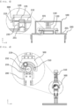
- FIG. 4 is a perspective view of the pouch curl prevention apparatus according to the embodiment of the present invention
- FIG. 5 is a front view and a partial enlarged view of the pouch curl prevention apparatus according to the embodiment of the present invention
- FIG. 6 is a side view and a partial enlarged view of the pouch curl prevention apparatus according to the embodiment of the present invention.
- the pouch curl prevention apparatus according to the present invention will be described with reference to FIGS. 4 to 6 .
- the pouch curl prevention apparatus receives the pouch film having the cup portion configured to receive the electrode assembly formed therein from the pouch film forming apparatus 10, rolls opposite surfaces of the pouch films at the edge of the cup portion using rollers to apply stress to curls formed at the pouch film in the pouch film forming process in an opposite direction, thereby alleviating or removing the curls.
- a driving unit configured to transfer the pouch film may be provided.
- a driving unit configured to individually drive each unit component of the pouch curl prevention apparatus may be separately provided.
- the pouch curl prevention apparatus may include an upper roller assembly 100 and a lower roller assembly 200.
- the lower roller assembly 200 includes a lower frame 201 coupled and fixed to the working table (not shown) of the pouch film forming apparatus 10.
- the lower frame 201 may include a vertical lower frame portion (not shown) coupled to the working table (not shown) of the pouch film forming apparatus 10 and a horizontal lower frame portion (not shown) located parallel to a wide surface of the pouch film 30 that passes through an upper end of the lower frame 201.
- the horizontal lower frame portion (not shown) may be disposed perpendicular to the transfer direction (x-axis direction) of the pouch film 30.
- a lower roller unit 230 may be located at the lower frame 201 in a state of being fixed thereto.
- a pair of lower roller fixing portions 233 may be located in a direction toward an upper part of the horizontal lower frame portion so as to be spaced apart from each other by a predetermined distance, and a lower roller shaft 232 may be located at the lower roller fixing portions 233 to fix a lower roller 231 to the lower roller fixing portions 233.
- the lower roller 231 may be formed in the shape of a cylinder and may have a through-hole formed in a direction toward a central axis of the cylinder such that the lower roller shaft 232 extends through the through-hole.
- the lower roller 231 is rotatable about the lower roller shaft 231.
- the rotational direction of the lower roller 231 may be identical to or opposite the transfer direction of the pouch film 30.
- a central axis of the lower roller 231 may be located parallel to the lateral direction (y-axis direction) of the pouch film 30.
- the pouch edge of the pouch film 30 supplied from the pouch film forming apparatus 10 is transferred rearwards in face-to-face contact with an outer circumferential surface of the pouch lower roller 231.
- the material for the lower roller 231 is not particularly restricted as long as the lower roller is capable of applying stress to the pouch film 30 that faces the lower roller.
- the lower roller may be made of an elastic material, more specifically a rigid elastic material.
- each of the lower roller fixing portions 233 is provided with an up and down position adjustment member configured to adjust the up and down position of the lower roller shaft 232 in a vertical direction (z-axis direction).
- the deformation angle of the pouch edge of the pouch film 30 that is horizontally transferred when passing through an upper end of an outer circumferential surface of the lower roller 231 may be changed. Consequently, reverse curls are differently formed depending on the extent of pouch curls formed during forming of the pouch film 30 at the front end, which is advantageous to alleviation or removal of the pouch curls.
- the upper roller assembly 100 may be located above the lower roller assembly 200.
- the upper roller assembly 100 may include an upper frame 101, wherein the upper frame 101 may include a horizontal upper frame portion (not shown) located parallel to the horizontal lower frame portion and a vertical upper frame portion (not shown).
- the vertical upper frame portion is coupled to an upper part of the horizontal lower frame portion.
- a vertical support portion 110 and a horizontal support portion 120 coupled and connected to the vertical support portion 110 may be located in a direction toward a lower end of the horizontal upper frame portion.
- the vertical support portion 110 may be formed in an upward and downward movable structure, and may adjust the up and down position of the horizontal support portion 120 connected thereto.
- the upper roller assembly 100 may include a position change portion 300.
- the position change portion 300 may be located at each of opposite ends of the horizontal support portion 120.
- the position change portion 300 may be formed in a plate shape.
- a through-hole (not shown) having a blocked arc shape may be formed in a central part of the position change portion such that an upper roller shaft 132, a description of which will follow, extends through the through-hole.
- a recessed portion 310 may be formed in a lower end of the through-hole, and the upper roller shaft 132 may be mounted in the recessed portion 310.
- a plurality of recessed portions 310 may be formed spaced apart from the center of the through-hole (not shown) having the blocked arc shape by a predetermined angle.
- the predetermined angle may be 30° or less, specifically 15° or less.
- the recessed portions 310 may be in symmetry with respect to a central axis of the arc-shaped through-hole in a vertical direction.
- An upper roller unit 130 may be mounted in the through-holes of the pair of position change portions 300.
- the upper roller unit 130 includes an upper roller shaft 132 mounted in the pair of position change portions 300 and a pair of upper rollers 131, through which the upper roller shaft 132 extends, the pair of upper rollers being located so as to correspond to the pair of lower rollers 231.
- a predetermined distance is defined between an outer circumferential surface of the lower roller 231 and an outer circumferential surface of the upper roller 131 that face each other, and the pouch edge of the pouch formed by the pouch film forming apparatus 10 may pass between the outer circumferential surfaces.
- the material for the upper roller 131 is not particularly restricted as long as the upper roller is capable of applying stress to the pouch film 30 that faces the upper roller.
- the upper roller may be made of an elastic material, more specifically a rigid elastic material.
- the upper roller 131 and the lower roller 231 may be rotated in the transfer direction of the pouch film 30 or a direction oppoiste thereto, and a separate driving portion and controller configured to rotate the upper roller 131 and the lower roller 231 at a predetermined speed may be provided.
- the horizontal position of the upper roller 131 or the lower roller 231 may be changed. This is advantageous to adjustment of the area of the pouch edge that passes between the upper roller 131 and the lower roller 231.
- Opposite ends of the upper roller shaft 132 may be mounted in the recessed portions 310 of the pair of position change portions 300.
- the upper roller shaft 132 may be selectively located at any one of the plurality of recessed portions 310. As described above, the position of the upper roller shaft 132 in the recessed portion 310 may be changed, whereby the distance between the upper roller 131 and the lower roller 231 that face each other may be changed, and therefore it is possible to change stress applied to the pouch edge that passes between the upper roller 131 and the lower roller 231.
- stress applied to the pouch edge may be changed depending on the extent of curls formed by the pouch film forming apparatus 10, whereby it is possible to effectively alleviate or remove curls and at the same time to reduce stress applied to the pouch edge, which is advantageous to prevention of damage to the pouch edge in a subsequent process.
- An upper roller shaft fixing portion 133 may be located at a side opposite the upper roller 131 in the state in which the position change portion 300 is disposed therebetween. After the position of the upper roller shaft 132 in the recessed portion 310 is changed, the fixing portion 133 fixes the upper roller shaft 132 to the position change portion 300. As a result, it is possible to prevent change in relative position of the upper roller 131 and the lower roller 231 and distance therebetween due to movement of the upper roller shaft 132 in an upward-downward direction (z-axis direction) and a leftward-rightward direction (y-axis direction). This is advantageous to prevention of damage to the pouch edge due to non-uniform stress applied to the pouch edge that passes between the upper roller 131 and the lower roller 231.
- the upper roller shaft fixing portion 133 may have a screw type shaft so as to be coupled to the upper roller shaft 132.
Landscapes
- Engineering & Computer Science (AREA)
- Mechanical Engineering (AREA)
- Chemical & Material Sciences (AREA)
- Chemical Kinetics & Catalysis (AREA)
- Electrochemistry (AREA)
- General Chemical & Material Sciences (AREA)
- Manufacturing & Machinery (AREA)
- Making Paper Articles (AREA)
- Blow-Moulding Or Thermoforming Of Plastics Or The Like (AREA)
- Packages (AREA)
Abstract
Description
- This application claims the benefit of priority to
Korean Patent Application No. 2021-0089816 filed on July 8, 2021 - The present invention relates to a battery module assembly apparatus with improved productivity and an assembly method using the same. More particularly, the present invention relates to a battery module assembly apparatus including two or more bonding units and capable of individually supplying a battery module to each bonding unit to electrically connect a battery cell and a busbar to each other and an assembly method using the same.
- With increasing demand for portable electronic devices, such as a smartphone, a tablet, and a laptop computer, demand for secondary batteries as energy sources thereof has also abruptly increased. Thereamong, a lithium secondary battery, which has high energy density and a long battery lifespan, has been most widely used.
- The lithium secondary battery includes an electrode assembly, configured such that a positive electrode sheet having a positive electrode active material applied thereto and a negative electrode sheet having a negative electrode active material applied thereto are disposed in the state in which a separator is interposed therebetween, and a battery case configured to receive the electrode assembly together with an electrolytic solution in a sealed state. Depending on the shape of a sheathing member, the lithium secondary battery may generally be classified as a can-shaped secondary battery having an electrode assembly mounted in a metal can or a pouch-shaped secondary battery having an electrode assembly mounted in a pouch made of an aluminum laminate sheet.
- In a process of manufacturing the pouch-shaped secondary battery, in order to reduce a dead space in a battery cell while stably mounting and fixing the electrode assembly, which has a predetermined volume, in the battery case, a process of forming an electrode assembly receiving portion in the laminate sheet is generally performed using a deep drawing apparatus.
-
FIG. 1 is an exploded perspective view schematically showing the construction of a general pouch-shaped secondary battery. - Referring to
FIG. 1 , the pouch-shaped secondary battery, which is a single cup type pouch-shaped secondary battery, includes apouch case 3 made of an aluminum laminate sheet and acell assembly 1 received in thepouch case 3, the cell assembly being configured such that a plurality of electrochemical cells, each of which includes a positive electrode, a separator, and a negative electrode, is stacked. As shown inFIG. 1 , thepouch case 3 is a single cup type pouch case configured such that connection is achieved at one edge thereof. Thepouch case 3 includes an upper pouch film 3 (a) and a lower pouch film 3 (b) . Acup portion 2 configured to allow thecell assembly 1 to be seated therein is formed in the lower pouch film 3(b). Thecup portion 2, which has a shape corresponding to the shape of thecell assembly 1, is formed in the lower pouch film 3(b) through a forming process, wherein the depth h of the cup portion is set depending on the thickness of thecell assembly 1. -
FIG. 2 is a process view showing a forming process in which a pouchfilm forming apparatus 10 forms a receiving portion in apouch film 30. (a) ofFIG. 2 is a forming process plan view, and (b) ofFIG. 2 is a forming process side view. - Referring to
FIG. 2 , the pouchfilm forming apparatus 10 includes apunch 11, astripper 12, and adie 13. Thedie 13 is provided with a seating recess (not shown) having a shape corresponding to the shape of a desired pouch case when the pouch case is formed using thepouch film 30. At this time, the depth of the seating recess corresponds to the depth of a receiving portion to be formed in the desired pouch case. In order to form a pouch case having a receiving portion of a desired depth using thepouch film 30, thepunch 11 applies pressure to thepouch film 30 disposed on thedie 13. That is, the punch presses the pouch film to form the pouch case. - During such a forming process, curls are generated at the pouch film, and defects occur due to curls in cutting and sealing processes after the pouch case forming process, whereby quality of a secondary battery is deteriorated.
-
Patent Document 1, which relates to a process of forming an electrode assembly receiving portion using a deep drawing apparatus capable of adjusting the tensile force of a laminate sheet, discloses technology in which a roller unit is located at an upper surface adjacent to an edge of a cup portion of a pouch in a forming process, the roller unit moves the laminate sheet, a second gripper side is pressed, whereby tensile force applied to the laminate sheet is reduced, and therefore wrinkles are prevented when the laminate sheet is pressed by a punch. -
Patent Document 2 discloses technology in which, in order to prevent generation of curls through rolling of a plurality of rollers in a cutting process to cut a part of an edge of a pouch after forming, a plurality of upper roller and lower roller pairs capable of rolling in contact with upper and lower surfaces adjacent to opposite edges of a pouch-shaped secondary battery is provided, a support frame configured to support a roller assembly is provided, the upper and lower rollers are located so as to correspond to each other, and a rolling operation is performed with respect to the upper and lower surfaces adjacent to the opposite edges of the pouch-shaped secondary battery, whereby stress is removed, thus preventing generation of curls. - However, a pouch curl prevention apparatus capable of applying stress to curls formed at an edge of a cup portion by pressing of a punch in a pouch forming process, which is recognized as an important problem in the present invention, in an opposite direction to alleviate the formed curls and being easily applicable to a conventional pouch forming process has not yet been proposed.
-
-
Korean Registered Patent Publication No. 10-2150010 Patent Document 1") -
Korean Registered Patent Publication No. 10-2224911 Patent Document 2") - The present invention has been made in view of the above problems, and it is an object of the present invention to provide a pouch curl prevention apparatus capable of applying stress to curls formed at an edge of a pouch in a pouch film forming process in an opposite direction to alleviate or remove the curls and being easily applicable to a conventional pouch film forming process.
- A pouch curl prevention apparatus according to the present invention to accomplish the above object is located at the rear of a pouch film forming apparatus and includes an upper roller assembly (100) including an upper roller (131) and a lower roller assembly (200) including a lower roller (231), wherein the upper roller (131) and the lower roller (231) are located so as to face each other, at least one of the upper roller (131) and the lower roller (231) is rotatable, and an upper roller unit (130) and a lower roller unit (230) are configured to pass a pouch film supplied from the pouch film forming apparatus therebetween.
- The upper roller (131) and the lower roller (231) may be located so as to face each other in a state of being spaced apart from each other by a predetermined distance, and a pouch edge of the pouch film supplied from the pouch film forming apparatus may pass between the upper roller (131) and the lower roller (231).
- The upper roller assembly (100) may include a pair of upper rollers (131) located spaced apart from each other by a predetermined distance, the lower roller assembly (200) may include a pair of lower rollers (231) located spaced apart from each other by a predetermined distance, and the pair of upper rollers (131) and the pair of lower rollers (231) may be located so as to face each other in a state of corresponding to each other.
- The upper roller assembly (100) may include a position change portion (300) of the upper roller.
- The position change portion (300) may include a plurality of recessed portions (310) configured to allow an upper roller shaft (132) of the upper roller unit (130) to be mounted therein.
- The position of the recessed portion (310) in which the upper roller shaft (132) is mounted may be changed to adjust the distance between the upper roller (131) and the lower roller (231).
- The distance between the pair of upper rollers (131) or the distance between the pair of lower rollers (231) may be adjustable.
- The upper roller assembly (100) may include a vertical support portion (110) configured to be movable upwards and downwards in order to adjust the height of the upper roller unit (130).
- The lower roller assembly (200) may include a lower roller fixing portion (233), and the lower roller fixing portion (233) may be provided with a position adjustment member configured to adjust the up and down position of the lower roller.
- At least one of the upper roller (131) and the lower roller (231) located so as to face each other may be made of an elastic material.
- In addition, the present invention may provide possible combinations of the above solving means.
- As is apparent from the above description, it is possible to apply stress curls generated at an edge of a pouch cup portion formed in a pouch film forming process according to the present invention in an opposite direction, whereby it is possible to alleviate or remove the generated curls.
- A pouch curl prevention apparatus according to the present invention is applied to produce pouch cases with improved quality, whereby it is possible to reduce a defect rate in a subsequent process and to manufacture a high-quality pouch-shaped secondary battery.
- The pouch curl prevention apparatus according to the present invention is easily applicable to a conventional pouch film forming process, whereby it is possible to improve economic efficiency in the pouch film forming process.
-
-
FIG. 1 is a schematic view showing the construction of a general pouch-shaped secondary battery. -
FIG. 2 is a process view showing a forming process in which a pouch film forming apparatus forms a cup portion in a pouch film. -
FIG. 3 is a process view showing a pouch film forming process using a pouch curl prevention apparatus according to an embodiment of the present invention. -
FIG. 4 is a perspective view of the pouch curl prevention apparatus according to the embodiment of the present invention. -
FIG. 5 is a front view and a partial enlarged view of the pouch curl prevention apparatus according to the embodiment of the present invention. -
FIG. 6 is a side view and a partial enlarged view of the pouch curl prevention apparatus according to the embodiment of the present invention. - Now, preferred embodiments of the present invention will be described in detail with reference to the accompanying drawings such that the preferred embodiments of the present invention can be easily implemented by a person having ordinary skill in the art to which the present invention pertains. In describing the principle of operation of the preferred embodiments of the present invention in detail, however, a detailed description of known functions and configurations incorporated herein will be omitted when the same may obscure the subject matter of the present invention.
- In addition, the same reference numbers will be used throughout the drawings to refer to parts that perform similar functions or operations. In the case in which one part is said to be connected to another part throughout the specification, not only may the one part be directly connected to the other part, but also, the one part may be indirectly connected to the other part via a further part. In addition, that a certain element is included does not mean that other elements are excluded, but means that such elements may be further included unless mentioned otherwise.
- In addition, a description to embody elements through limitation or addition may be applied to all inventions, unless particularly restricted, and does not limit a specific invention.
- Also, in the description of the invention and the claims of the present application, singular forms are intended to include plural forms unless mentioned otherwise.
- Also, in the description of the invention and the claims of the present application, "or" includes "and" unless mentioned otherwise. Therefore, "including A or B" means three cases, namely, the case including A, the case including B, and the case including A and B.
- In addition, all numeric ranges include the lowest value, the highest value, and all intermediate values therebetween unless the context clearly indicates otherwise.
- Hereinafter, a pouch curl prevention apparatus according to the present invention will be described in detail with reference to the accompanying drawings.
-
FIG. 3 is a process view showing a pouch film forming process using a pouch curl prevention apparatus according to an embodiment of the present invention. InFIG. 3, (c) is a process plan view, and (d) is a process side view. - Referring to
FIG. 3 , the pouch curl prevention apparatus according to the present invention is located so as to be used after a step of forming a pouch film to form a cup portion in a pouch film forming process, and specifically is located at the rear of a pouchfilm forming apparatus 10 in a transfer direction of thepouch film 30. - In the present invention, the
pouch film 30 may be a laminate sheet having a structure in which insulative layers each made of a polymer material are joined to opposite surfaces of a metal layer. Each of the insulative layers may have a thickness of approximately 30 um to 40 um, and may be coated or laminated on the metal layer. An upper one of the insulative layers is a polymer film layer that is thermally fusible, and a lower one of the insulative layers is a polymer film layer that functions as an outer protective layer. Meanwhile, the metal layer may be made of any one selected from among an alloy of iron, carbon, chromium, and manganese, an alloy of iron, chromium, and nickel, aluminum, or an equivalent thereto, and aluminum metal foil is widely used. - The pouch
film forming apparatus 10 may include a die 13 configured to allow thepouch film 30 to be disposed thereon, astripper 12 configured to press thepouch film 30 disposed on the die 13 in order to fix thepouch film 30, and apunch 11 configured to press thepouch film 30 disposed on the die 13 in order to shape an electrode assembly receiving portion. In addition, the pouch film forming apparatus may include a working table (not shown) configured to support the above-described components and to transfer thepouch film 30 to a subsequent process. - As shown in
FIG. 3 , thedie 13 is configured to allow thepouch film 30 to be disposed thereon, and a die holder (not shown) configured to fix thedie 13, on which thepouch film 30 is disposed, may be included. Here, thedie 13 has a smaller area than the die holder (not shown), and is provided in an upper surface thereof with a shaping portion (not shown) configured to shape a cup portion that receives an electrode assembly in thepouch film 30. - The
stripper 12, which is configured to fix the pouch film disposed on thedie 13, may be provided above the die 13 so as to be movable upwards and downwards, and may press thepouch film 30 disposed on the die 13 so as to be fixed when being moved downwards. Thestripper 12 may have a size corresponding to the size of the upper surface of the die 13, and may be provided in an upper surface thereof with a through-hole (not shown) having the same size as the shaping portion (not shown) provided in thedie 13. - The
punch 11 is provided above the die 13 so as to be movable upwards and downwards, and is inserted into the shaping portion to shape an electrode assembly receiving portion in thepouch film 30 when being moved downwards. A driving unit (not shown) configured to move thepunch 11 in an upward-downward direction is included. Thepunch 11 is moved downwards by the driving unit, passes through the through-hole of thestripper 12, and is inserted into the shaping portion. At this time, the punch is inserted into the shaping portion in the state in which thepouch film 30 located in the shaping portion is pressed, whereby it is possible to shape an electrode assembly receiving portion having a shape corresponding to the shape of the shaping portion in thepouch film 30. After shaping of the receiving portion, thedie 13 and thestripper 12 are moved upwards, thepouch film 30 having the cup portion configured to receive the electrode assembly formed therein is transferred rearwards by a pouch film transfer member (not shown), and curls formed at a pouch edge are alleviated or removed by the pouch curl prevention apparatus located at the rear. The pouch edge may be a part of thepouch film 30 in which the cup portion configured to receive the electrode assembly is not formed, specifically a non-forming part of thepouch film 30 from opposite peripheries of the pouch film to a periphery of the cup portion located parallel to the peripheries of the pouch film. - In the present invention, the pouch curl prevention apparatus is located at the rear of the pouch
film forming apparatus 10 in the transfer direction of thepouch film 30. - Referring to
FIG. 3 , the pouch curl prevention apparatus includes a pair ofupper rollers 131 and a pair oflower rollers 231 located spaced apart from each other by a predetermined distance in a lateral direction (y-axis direction) of thepouch film 30. - The
punch 11 and the shaping portion (not shown) of thedie 13 of the pouchfilm forming apparatus 10 are located between the twoupper rollers 131 and between the twolower rollers 231 in the lateral direction (y-axis direction) of thepouch film 30. In addition, the pair ofupper rollers 131 and the pair oflower rollers 231 are located at the edge of the cup portion configured to receive the electrode assembly formed by the pouchfilm forming apparatus 10 in the lateral direction (y-axis direction) of thepouch film 30. -
FIG. 4 is a perspective view of the pouch curl prevention apparatus according to the embodiment of the present invention,FIG. 5 is a front view and a partial enlarged view of the pouch curl prevention apparatus according to the embodiment of the present invention, andFIG. 6 is a side view and a partial enlarged view of the pouch curl prevention apparatus according to the embodiment of the present invention. - The pouch curl prevention apparatus according to the present invention will be described with reference to
FIGS. 4 to 6 . - The pouch curl prevention apparatus according to the present invention receives the pouch film having the cup portion configured to receive the electrode assembly formed therein from the pouch
film forming apparatus 10, rolls opposite surfaces of the pouch films at the edge of the cup portion using rollers to apply stress to curls formed at the pouch film in the pouch film forming process in an opposite direction, thereby alleviating or removing the curls. Here, a driving unit configured to transfer the pouch film may be provided. In addition, a driving unit configured to individually drive each unit component of the pouch curl prevention apparatus may be separately provided. - The pouch curl prevention apparatus may include an
upper roller assembly 100 and alower roller assembly 200. - First, the
lower roller assembly 200 will be described. - The
lower roller assembly 200 includes alower frame 201 coupled and fixed to the working table (not shown) of the pouchfilm forming apparatus 10. Thelower frame 201 may include a vertical lower frame portion (not shown) coupled to the working table (not shown) of the pouchfilm forming apparatus 10 and a horizontal lower frame portion (not shown) located parallel to a wide surface of thepouch film 30 that passes through an upper end of thelower frame 201. Specifically, the horizontal lower frame portion (not shown) may be disposed perpendicular to the transfer direction (x-axis direction) of thepouch film 30. Alower roller unit 230 may be located at thelower frame 201 in a state of being fixed thereto. Specifically, a pair of lowerroller fixing portions 233 may be located in a direction toward an upper part of the horizontal lower frame portion so as to be spaced apart from each other by a predetermined distance, and alower roller shaft 232 may be located at the lowerroller fixing portions 233 to fix alower roller 231 to the lowerroller fixing portions 233. - The
lower roller 231 may be formed in the shape of a cylinder and may have a through-hole formed in a direction toward a central axis of the cylinder such that thelower roller shaft 232 extends through the through-hole. Thelower roller 231 is rotatable about thelower roller shaft 231. The rotational direction of thelower roller 231 may be identical to or opposite the transfer direction of thepouch film 30. In addition, a central axis of thelower roller 231 may be located parallel to the lateral direction (y-axis direction) of thepouch film 30. - The pouch edge of the
pouch film 30 supplied from the pouchfilm forming apparatus 10 is transferred rearwards in face-to-face contact with an outer circumferential surface of the pouchlower roller 231. Here, the material for thelower roller 231 is not particularly restricted as long as the lower roller is capable of applying stress to thepouch film 30 that faces the lower roller. Specifically, the lower roller may be made of an elastic material, more specifically a rigid elastic material. - Here, each of the lower
roller fixing portions 233 is provided with an up and down position adjustment member configured to adjust the up and down position of thelower roller shaft 232 in a vertical direction (z-axis direction). As a result, the deformation angle of the pouch edge of thepouch film 30 that is horizontally transferred when passing through an upper end of an outer circumferential surface of thelower roller 231 may be changed. Consequently, reverse curls are differently formed depending on the extent of pouch curls formed during forming of thepouch film 30 at the front end, which is advantageous to alleviation or removal of the pouch curls. - Next, the
upper roller assembly 100 will be described. - The
upper roller assembly 100 may be located above thelower roller assembly 200. Theupper roller assembly 100 may include anupper frame 101, wherein theupper frame 101 may include a horizontal upper frame portion (not shown) located parallel to the horizontal lower frame portion and a vertical upper frame portion (not shown). The vertical upper frame portion is coupled to an upper part of the horizontal lower frame portion. - A
vertical support portion 110 and ahorizontal support portion 120 coupled and connected to thevertical support portion 110 may be located in a direction toward a lower end of the horizontal upper frame portion. Thevertical support portion 110 may be formed in an upward and downward movable structure, and may adjust the up and down position of thehorizontal support portion 120 connected thereto. - The
upper roller assembly 100 may include aposition change portion 300. Theposition change portion 300 may be located at each of opposite ends of thehorizontal support portion 120. Theposition change portion 300 may be formed in a plate shape. Specifically, a through-hole (not shown) having a blocked arc shape may be formed in a central part of the position change portion such that anupper roller shaft 132, a description of which will follow, extends through the through-hole. Here, a recessedportion 310 may be formed in a lower end of the through-hole, and theupper roller shaft 132 may be mounted in the recessedportion 310. A plurality of recessedportions 310 may be formed spaced apart from the center of the through-hole (not shown) having the blocked arc shape by a predetermined angle. The predetermined angle may be 30° or less, specifically 15° or less. In addition, the recessedportions 310 may be in symmetry with respect to a central axis of the arc-shaped through-hole in a vertical direction. - An
upper roller unit 130 may be mounted in the through-holes of the pair ofposition change portions 300. Theupper roller unit 130 includes anupper roller shaft 132 mounted in the pair ofposition change portions 300 and a pair ofupper rollers 131, through which theupper roller shaft 132 extends, the pair of upper rollers being located so as to correspond to the pair oflower rollers 231. A predetermined distance is defined between an outer circumferential surface of thelower roller 231 and an outer circumferential surface of theupper roller 131 that face each other, and the pouch edge of the pouch formed by the pouchfilm forming apparatus 10 may pass between the outer circumferential surfaces. In the same manner, the material for theupper roller 131 is not particularly restricted as long as the upper roller is capable of applying stress to thepouch film 30 that faces the upper roller. Specifically, the upper roller may be made of an elastic material, more specifically a rigid elastic material. - Here, the
upper roller 131 and thelower roller 231 may be rotated in the transfer direction of thepouch film 30 or a direction oppoiste thereto, and a separate driving portion and controller configured to rotate theupper roller 131 and thelower roller 231 at a predetermined speed may be provided. - The horizontal position of the
upper roller 131 or thelower roller 231 may be changed. This is advantageous to adjustment of the area of the pouch edge that passes between theupper roller 131 and thelower roller 231. - Opposite ends of the
upper roller shaft 132 may be mounted in the recessedportions 310 of the pair ofposition change portions 300. In addition, theupper roller shaft 132 may be selectively located at any one of the plurality of recessedportions 310. As described above, the position of theupper roller shaft 132 in the recessedportion 310 may be changed, whereby the distance between theupper roller 131 and thelower roller 231 that face each other may be changed, and therefore it is possible to change stress applied to the pouch edge that passes between theupper roller 131 and thelower roller 231. Consequently, stress applied to the pouch edge may be changed depending on the extent of curls formed by the pouchfilm forming apparatus 10, whereby it is possible to effectively alleviate or remove curls and at the same time to reduce stress applied to the pouch edge, which is advantageous to prevention of damage to the pouch edge in a subsequent process. - An upper roller
shaft fixing portion 133 may be located at a side opposite theupper roller 131 in the state in which theposition change portion 300 is disposed therebetween. After the position of theupper roller shaft 132 in the recessedportion 310 is changed, the fixingportion 133 fixes theupper roller shaft 132 to theposition change portion 300. As a result, it is possible to prevent change in relative position of theupper roller 131 and thelower roller 231 and distance therebetween due to movement of theupper roller shaft 132 in an upward-downward direction (z-axis direction) and a leftward-rightward direction (y-axis direction). This is advantageous to prevention of damage to the pouch edge due to non-uniform stress applied to the pouch edge that passes between theupper roller 131 and thelower roller 231. The upper rollershaft fixing portion 133 may have a screw type shaft so as to be coupled to theupper roller shaft 132. - Although the specific details of the present invention have been described in detail, those skilled in the art will appreciate that the detailed description thereof discloses only preferred embodiments of the present invention and thus does not limit the scope of the present invention. Accordingly, those skilled in the art will appreciate that various changes and modifications are possible, without departing from the category and technical idea of the present invention, and it will be obvious that such changes and modifications fall within the scope of the appended claims.
-
- 1:
- Cell assembly
- 2:
- Cup portion
- 3:
- Pouch case
- 3(a):
- Upper pouch film
- 3(b):
- Lower pouch film
- 10:
- Pouch film forming apparatus
- 11:
- Punch
- 12:
- Stripper
- 13:
- Die
- 30:
- Pouch film
- 100:
- Upper roller assembly
- 101:
- Upper frame
- 110:
- Vertical support portion
- 120:
- Horizontal support portion
- 130:
- Upper roller unit
- 131:
- Upper roller
- 132:
- Upper roller shaft
- 133:
- Upper roller shaft fixing portion
- 200:
- Lower roller assembly
- 201:
- Lower frame
- 230:
- Lower roller unit
- 231:
- Lower roller
- 232:
- Lower roller shaft
- 233:
- Lower roller fixing portion
- 300:
- Position change portion
- 310:
- Recessed portion
Claims (10)
- A pouch curl prevention apparatus located at a rear of a pouch film forming apparatus, the pouch curl prevention apparatus comprising:an upper roller assembly comprising an upper roller; anda lower roller assembly comprising a lower roller, whereinthe upper roller and the lower roller are located so as to face each other,at least one of the upper roller and the lower roller is rotatable, andwherein an upper roller unit and a lower roller unit are configured to pass a pouch film supplied from the pouch film forming apparatus therebetween.
- The pouch curl prevention apparatus according to claim 1, whereinthe upper roller and the lower roller are located so as to face each other in a state of being spaced apart from each other by a predetermined distance, anda pouch edge of the pouch film supplied from the pouch film forming apparatus passes between the upper roller and the lower roller.
- The pouch curl prevention apparatus according to claim 1, whereinthe upper roller assembly comprises a pair of upper rollers located spaced apart from each other by a predetermined distance,the lower roller assembly comprises a pair of lower rollers located spaced apart from each other by a predetermined distance, andthe pair of upper rollers and the pair of lower rollers are located so as to face each other in a state of corresponding to each other.
- The pouch curl prevention apparatus according to claim 1, wherein the upper roller assembly comprises a position change portion of the upper roller.
- The pouch curl prevention apparatus according to claim 4, wherein the position change portion comprises a plurality of recessed portions configured to allow an upper roller shaft of the upper roller unit to be mounted therein.
- The pouch curl prevention apparatus according to claim 5, wherein a position of the recessed portion in which the upper roller shaft is mounted is changable to adjust a distance between the upper roller and the lower roller.
- The pouch curl prevention apparatus according to claim 3, wherein a distance between the pair of upper rollers or a distance between the pair of lower rollers is adjustable.
- The pouch curl prevention apparatus according to claim 1, wherein the upper roller assembly comprises a vertical support portion configured to be movable upwards and downwards in order to adjust a height of the upper roller unit.
- The pouch curl prevention apparatus according to claim 1, whereinthe lower roller assembly comprises a lower roller fixing portion, andthe lower roller fixing portion is provided with a position adjustment member configured to adjust an up and down position of the lower roller.
- The pouch curl prevention apparatus according to claim 2, wherein at least one of the upper roller and the lower roller located so as to face each other is made of an elastic material.
Applications Claiming Priority (2)
| Application Number | Priority Date | Filing Date | Title |
|---|---|---|---|
| KR1020210089816A KR20230009141A (en) | 2021-07-08 | 2021-07-08 | Pouch Curling Prevention Device |
| PCT/KR2022/009902 WO2023282681A1 (en) | 2021-07-08 | 2022-07-08 | Pouch curling prevention device |
Publications (3)
| Publication Number | Publication Date |
|---|---|
| EP4194176A1 true EP4194176A1 (en) | 2023-06-14 |
| EP4194176A4 EP4194176A4 (en) | 2024-03-27 |
| EP4194176B1 EP4194176B1 (en) | 2024-10-23 |
Family
ID=84801761
Family Applications (1)
| Application Number | Title | Priority Date | Filing Date |
|---|---|---|---|
| EP22838033.3A Active EP4194176B1 (en) | 2021-07-08 | 2022-07-08 | Pouch curl prevention apparatus |
Country Status (8)
| Country | Link |
|---|---|
| US (1) | US20230286205A1 (en) |
| EP (1) | EP4194176B1 (en) |
| JP (1) | JP7520447B2 (en) |
| KR (1) | KR20230009141A (en) |
| CN (1) | CN115868072A (en) |
| ES (1) | ES2996583T3 (en) |
| HU (1) | HUE069055T2 (en) |
| WO (1) | WO2023282681A1 (en) |
Families Citing this family (2)
| Publication number | Priority date | Publication date | Assignee | Title |
|---|---|---|---|---|
| KR20240136656A (en) | 2023-03-07 | 2024-09-19 | 주식회사 엘지에너지솔루션 | Apparatus for supplying a pouch film and method for supplying a pouch film using the same |
| KR20250058611A (en) * | 2023-10-23 | 2025-04-30 | 주식회사 엘지에너지솔루션 | Pouch cutting appartus |
Family Cites Families (18)
| Publication number | Priority date | Publication date | Assignee | Title |
|---|---|---|---|---|
| US5632133A (en) * | 1994-02-22 | 1997-05-27 | Wyslotsky; Ihor | Method of pre-formed in-line thermofusing of multilayer polymeric films to form packaging components |
| JP2000288664A (en) | 1999-04-12 | 2000-10-17 | Kyodo Printing Co Ltd | Sheet conveying device of press forming machine |
| AU2003300889A1 (en) * | 2002-12-13 | 2004-07-09 | Sanford Redmond, Inc. | Machine to make e-z open pouch with flap and bulge |
| JP5176347B2 (en) * | 2007-03-08 | 2013-04-03 | トヨタ自動車株式会社 | Electrode plate pressing method and electrode plate pressing apparatus |
| US8459081B2 (en) * | 2009-06-29 | 2013-06-11 | Mestek Machinery, Inc. | Continuously smoothly adjustable and self-aligning variable width roll forming apparatus |
| CN203331107U (en) * | 2013-07-01 | 2013-12-11 | 浙江万向亿能动力电池有限公司 | Air cooling device for flexible package lithium ion battery slitting |
| JP6178152B2 (en) | 2013-08-01 | 2017-08-09 | 株式会社脇坂エンジニアリング | Thermoforming equipment |
| KR102065127B1 (en) * | 2016-04-04 | 2020-01-10 | 주식회사 엘지화학 | Electrode winding device |
| JP6704313B2 (en) | 2016-08-10 | 2020-06-03 | 株式会社脇坂エンジニアリング | Trimming device |
| KR102150010B1 (en) | 2016-09-21 | 2020-08-31 | 주식회사 엘지화학 | Deep Drawing Apparatus for Laminated Sheet Capable of Adjusting Tension and Method for Deep Drawing Using the Same |
| KR20180092174A (en) * | 2017-02-08 | 2018-08-17 | 주식회사 엘지화학 | Apparatus and method for forming pouch of secondary battery secured residual thickness |
| KR102224911B1 (en) * | 2017-03-20 | 2021-03-05 | 주식회사 엘지화학 | Leveling apparatus for preventing curling of pouch type secondary battery |
| CN208944968U (en) * | 2018-10-15 | 2019-06-07 | 东莞市金耐尔能源科技有限公司 | A kind of soft package lithium battery rushes shell machine automatically |
| KR101958882B1 (en) * | 2018-12-06 | 2019-03-15 | (주)하나기술 | Folding roller for periphery of prismatic battery |
| KR102403858B1 (en) * | 2019-09-30 | 2022-06-02 | 에스케이온 주식회사 | Folding apparatus and method for pouch case of battery cell |
| KR102591518B1 (en) * | 2019-12-11 | 2023-10-19 | 삼성에스디아이 주식회사 | Battery pack and label sheet for the same |
| KR20210089816A (en) | 2020-01-08 | 2021-07-19 | 현대자동차주식회사 | Device for torque vectoring |
| KR102230937B1 (en) * | 2020-08-07 | 2021-03-23 | 주식회사 와이에이치티 | Folding system for folding terrace of secondary battery cell |
-
2021
- 2021-07-08 KR KR1020210089816A patent/KR20230009141A/en active Pending
-
2022
- 2022-07-08 US US18/017,783 patent/US20230286205A1/en active Pending
- 2022-07-08 JP JP2022580995A patent/JP7520447B2/en active Active
- 2022-07-08 EP EP22838033.3A patent/EP4194176B1/en active Active
- 2022-07-08 ES ES22838033T patent/ES2996583T3/en active Active
- 2022-07-08 WO PCT/KR2022/009902 patent/WO2023282681A1/en not_active Ceased
- 2022-07-08 CN CN202280005516.8A patent/CN115868072A/en active Pending
- 2022-07-08 HU HUE22838033A patent/HUE069055T2/en unknown
Also Published As
| Publication number | Publication date |
|---|---|
| EP4194176A4 (en) | 2024-03-27 |
| JP2023536566A (en) | 2023-08-28 |
| JP7520447B2 (en) | 2024-07-23 |
| HUE069055T2 (en) | 2025-02-28 |
| CN115868072A (en) | 2023-03-28 |
| KR20230009141A (en) | 2023-01-17 |
| EP4194176B1 (en) | 2024-10-23 |
| US20230286205A1 (en) | 2023-09-14 |
| ES2996583T3 (en) | 2025-02-12 |
| WO2023282681A1 (en) | 2023-01-12 |
Similar Documents
| Publication | Publication Date | Title |
|---|---|---|
| EP4194176B1 (en) | Pouch curl prevention apparatus | |
| JP5908128B2 (en) | Battery case for secondary battery | |
| JP6115683B2 (en) | Battery cell pressurizer | |
| US20010008719A1 (en) | Plate with regular projections, and device and method for forming the plate | |
| KR101443832B1 (en) | A manufacturing Apparatus for Secondary Battery Case and Method for preparation of the same | |
| KR102065363B1 (en) | Electrode and manufacturing method for the electrode and roller for the electrode manufacturing | |
| JP6551220B2 (en) | Manufacturing method of all solid state battery | |
| CN109689365B (en) | Leveling apparatus for preventing pouch type secondary battery from curling | |
| JP6996408B2 (en) | How to transport separator material for fuel cells | |
| JP2023541460A (en) | Pouch case manufacturing equipment and pouch case manufacturing method | |
| KR20200131614A (en) | Electrode assembly manufacturing device, electrode assembly manufactured from thereof and rechargeable battery | |
| JP2009193868A (en) | Separator welding method, separator welding apparatus and separator | |
| JP2006228533A (en) | Method of forming separator for fuel cell and separator shape correcting device | |
| HK1041110B (en) | Electrode for battery, manufacturing method thereof, and apparatus for it | |
| KR20180123331A (en) | Secondary battery, apparatus and method for manufacturing the same | |
| US20220131206A1 (en) | Cooling device for cooling an energy accumulator and/or electronic assembly and method of manufacturing the same | |
| CN218424963U (en) | Utmost point ear equipment of buckling | |
| CN114243121B (en) | Lithium battery and manufacturing method thereof | |
| EP4184634B1 (en) | Cutting device and lamination equipment and method for secondary battery comprising same | |
| JP2024072135A (en) | LAMINATE MANUFACTURING APPARATUS AND METHOD FOR MANUFACTURING LAMINATE | |
| US20250229518A1 (en) | Press bonding apparatus for electrode foil of a lithium metal secondary battery | |
| EP4212311B1 (en) | Pouch sealing apparatus | |
| KR102790764B1 (en) | Rotating notching device for film cutting | |
| JP2013020859A (en) | Laminate structure generator, and stacking method and apparatus for secondary cell including the same | |
| JP2012182140A (en) | Separator |
Legal Events
| Date | Code | Title | Description |
|---|---|---|---|
| STAA | Information on the status of an ep patent application or granted ep patent |
Free format text: STATUS: THE INTERNATIONAL PUBLICATION HAS BEEN MADE |
|
| PUAI | Public reference made under article 153(3) epc to a published international application that has entered the european phase |
Free format text: ORIGINAL CODE: 0009012 |
|
| STAA | Information on the status of an ep patent application or granted ep patent |
Free format text: STATUS: REQUEST FOR EXAMINATION WAS MADE |
|
| 17P | Request for examination filed |
Effective date: 20230309 |
|
| AK | Designated contracting states |
Kind code of ref document: A1 Designated state(s): AL AT BE BG CH CY CZ DE DK EE ES FI FR GB GR HR HU IE IS IT LI LT LU LV MC MK MT NL NO PL PT RO RS SE SI SK SM TR |
|
| A4 | Supplementary search report drawn up and despatched |
Effective date: 20240227 |
|
| RIC1 | Information provided on ipc code assigned before grant |
Ipc: B29L 31/34 20060101ALN20240221BHEP Ipc: B29L 31/00 20060101ALN20240221BHEP Ipc: B29C 51/04 20060101ALI20240221BHEP Ipc: B29C 51/08 20060101ALI20240221BHEP Ipc: H01M 10/04 20060101ALI20240221BHEP Ipc: H01M 50/105 20210101ALI20240221BHEP Ipc: B29C 51/26 20060101AFI20240221BHEP |
|
| GRAP | Despatch of communication of intention to grant a patent |
Free format text: ORIGINAL CODE: EPIDOSNIGR1 |
|
| STAA | Information on the status of an ep patent application or granted ep patent |
Free format text: STATUS: GRANT OF PATENT IS INTENDED |
|
| GRAS | Grant fee paid |
Free format text: ORIGINAL CODE: EPIDOSNIGR3 |
|
| RIC1 | Information provided on ipc code assigned before grant |
Ipc: B29L 31/34 20060101ALN20240809BHEP Ipc: B29L 31/00 20060101ALN20240809BHEP Ipc: B29C 51/04 20060101ALI20240809BHEP Ipc: B29C 51/08 20060101ALI20240809BHEP Ipc: H01M 10/04 20060101ALI20240809BHEP Ipc: H01M 50/105 20210101ALI20240809BHEP Ipc: B29C 51/26 20060101AFI20240809BHEP |
|
| GRAA | (expected) grant |
Free format text: ORIGINAL CODE: 0009210 |
|
| STAA | Information on the status of an ep patent application or granted ep patent |
Free format text: STATUS: THE PATENT HAS BEEN GRANTED |
|
| DAV | Request for validation of the european patent (deleted) | ||
| DAX | Request for extension of the european patent (deleted) | ||
| INTG | Intention to grant announced |
Effective date: 20240823 |
|
| P01 | Opt-out of the competence of the unified patent court (upc) registered |
Free format text: CASE NUMBER: APP_49821/2024 Effective date: 20240903 |
|
| AK | Designated contracting states |
Kind code of ref document: B1 Designated state(s): AL AT BE BG CH CY CZ DE DK EE ES FI FR GB GR HR HU IE IS IT LI LT LU LV MC MK MT NL NO PL PT RO RS SE SI SK SM TR |
|
| REG | Reference to a national code |
Ref country code: GB Ref legal event code: FG4D |
|
| REG | Reference to a national code |
Ref country code: CH Ref legal event code: EP |
|
| REG | Reference to a national code |
Ref country code: DE Ref legal event code: R096 Ref document number: 602022007111 Country of ref document: DE |
|
| REG | Reference to a national code |
Ref country code: IE Ref legal event code: FG4D |
|
| REG | Reference to a national code |
Ref country code: ES Ref legal event code: FG2A Ref document number: 2996583 Country of ref document: ES Kind code of ref document: T3 Effective date: 20250212 |
|
| REG | Reference to a national code |
Ref country code: LT Ref legal event code: MG9D |
|
| REG | Reference to a national code |
Ref country code: NL Ref legal event code: MP Effective date: 20241023 |
|
| REG | Reference to a national code |
Ref country code: HU Ref legal event code: AG4A Ref document number: E069055 Country of ref document: HU |
|
| REG | Reference to a national code |
Ref country code: AT Ref legal event code: MK05 Ref document number: 1734500 Country of ref document: AT Kind code of ref document: T Effective date: 20241023 |
|
| PG25 | Lapsed in a contracting state [announced via postgrant information from national office to epo] |
Ref country code: NL Free format text: LAPSE BECAUSE OF FAILURE TO SUBMIT A TRANSLATION OF THE DESCRIPTION OR TO PAY THE FEE WITHIN THE PRESCRIBED TIME-LIMIT Effective date: 20241023 |
|
| PG25 | Lapsed in a contracting state [announced via postgrant information from national office to epo] |
Ref country code: NL Free format text: LAPSE BECAUSE OF FAILURE TO SUBMIT A TRANSLATION OF THE DESCRIPTION OR TO PAY THE FEE WITHIN THE PRESCRIBED TIME-LIMIT Effective date: 20241023 |
|
| PG25 | Lapsed in a contracting state [announced via postgrant information from national office to epo] |
Ref country code: IS Free format text: LAPSE BECAUSE OF FAILURE TO SUBMIT A TRANSLATION OF THE DESCRIPTION OR TO PAY THE FEE WITHIN THE PRESCRIBED TIME-LIMIT Effective date: 20250223 Ref country code: PT Free format text: LAPSE BECAUSE OF FAILURE TO SUBMIT A TRANSLATION OF THE DESCRIPTION OR TO PAY THE FEE WITHIN THE PRESCRIBED TIME-LIMIT Effective date: 20250224 Ref country code: HR Free format text: LAPSE BECAUSE OF FAILURE TO SUBMIT A TRANSLATION OF THE DESCRIPTION OR TO PAY THE FEE WITHIN THE PRESCRIBED TIME-LIMIT Effective date: 20241023 |
|
| PG25 | Lapsed in a contracting state [announced via postgrant information from national office to epo] |
Ref country code: FI Free format text: LAPSE BECAUSE OF FAILURE TO SUBMIT A TRANSLATION OF THE DESCRIPTION OR TO PAY THE FEE WITHIN THE PRESCRIBED TIME-LIMIT Effective date: 20241023 |
|
| PG25 | Lapsed in a contracting state [announced via postgrant information from national office to epo] |
Ref country code: BG Free format text: LAPSE BECAUSE OF FAILURE TO SUBMIT A TRANSLATION OF THE DESCRIPTION OR TO PAY THE FEE WITHIN THE PRESCRIBED TIME-LIMIT Effective date: 20241023 |
|
| PG25 | Lapsed in a contracting state [announced via postgrant information from national office to epo] |
Ref country code: NO Free format text: LAPSE BECAUSE OF FAILURE TO SUBMIT A TRANSLATION OF THE DESCRIPTION OR TO PAY THE FEE WITHIN THE PRESCRIBED TIME-LIMIT Effective date: 20250123 |
|
| PG25 | Lapsed in a contracting state [announced via postgrant information from national office to epo] |
Ref country code: LV Free format text: LAPSE BECAUSE OF FAILURE TO SUBMIT A TRANSLATION OF THE DESCRIPTION OR TO PAY THE FEE WITHIN THE PRESCRIBED TIME-LIMIT Effective date: 20241023 Ref country code: GR Free format text: LAPSE BECAUSE OF FAILURE TO SUBMIT A TRANSLATION OF THE DESCRIPTION OR TO PAY THE FEE WITHIN THE PRESCRIBED TIME-LIMIT Effective date: 20250124 Ref country code: AT Free format text: LAPSE BECAUSE OF FAILURE TO SUBMIT A TRANSLATION OF THE DESCRIPTION OR TO PAY THE FEE WITHIN THE PRESCRIBED TIME-LIMIT Effective date: 20241023 |
|
| PG25 | Lapsed in a contracting state [announced via postgrant information from national office to epo] |
Ref country code: PL Free format text: LAPSE BECAUSE OF FAILURE TO SUBMIT A TRANSLATION OF THE DESCRIPTION OR TO PAY THE FEE WITHIN THE PRESCRIBED TIME-LIMIT Effective date: 20241023 |
|
| PG25 | Lapsed in a contracting state [announced via postgrant information from national office to epo] |
Ref country code: RS Free format text: LAPSE BECAUSE OF FAILURE TO SUBMIT A TRANSLATION OF THE DESCRIPTION OR TO PAY THE FEE WITHIN THE PRESCRIBED TIME-LIMIT Effective date: 20250123 |
|
| PG25 | Lapsed in a contracting state [announced via postgrant information from national office to epo] |
Ref country code: SM Free format text: LAPSE BECAUSE OF FAILURE TO SUBMIT A TRANSLATION OF THE DESCRIPTION OR TO PAY THE FEE WITHIN THE PRESCRIBED TIME-LIMIT Effective date: 20241023 |
|
| PG25 | Lapsed in a contracting state [announced via postgrant information from national office to epo] |
Ref country code: DK Free format text: LAPSE BECAUSE OF FAILURE TO SUBMIT A TRANSLATION OF THE DESCRIPTION OR TO PAY THE FEE WITHIN THE PRESCRIBED TIME-LIMIT Effective date: 20241023 |
|
| PGFP | Annual fee paid to national office [announced via postgrant information from national office to epo] |
Ref country code: BE Payment date: 20250407 Year of fee payment: 4 |
|
| PG25 | Lapsed in a contracting state [announced via postgrant information from national office to epo] |
Ref country code: EE Free format text: LAPSE BECAUSE OF FAILURE TO SUBMIT A TRANSLATION OF THE DESCRIPTION OR TO PAY THE FEE WITHIN THE PRESCRIBED TIME-LIMIT Effective date: 20241023 |
|
| PGFP | Annual fee paid to national office [announced via postgrant information from national office to epo] |
Ref country code: FR Payment date: 20250624 Year of fee payment: 4 |
|
| PG25 | Lapsed in a contracting state [announced via postgrant information from national office to epo] |
Ref country code: RO Free format text: LAPSE BECAUSE OF FAILURE TO SUBMIT A TRANSLATION OF THE DESCRIPTION OR TO PAY THE FEE WITHIN THE PRESCRIBED TIME-LIMIT Effective date: 20241023 |
|
| REG | Reference to a national code |
Ref country code: DE Ref legal event code: R097 Ref document number: 602022007111 Country of ref document: DE |
|
| PG25 | Lapsed in a contracting state [announced via postgrant information from national office to epo] |
Ref country code: SK Free format text: LAPSE BECAUSE OF FAILURE TO SUBMIT A TRANSLATION OF THE DESCRIPTION OR TO PAY THE FEE WITHIN THE PRESCRIBED TIME-LIMIT Effective date: 20241023 |
|
| PG25 | Lapsed in a contracting state [announced via postgrant information from national office to epo] |
Ref country code: CZ Free format text: LAPSE BECAUSE OF FAILURE TO SUBMIT A TRANSLATION OF THE DESCRIPTION OR TO PAY THE FEE WITHIN THE PRESCRIBED TIME-LIMIT Effective date: 20241023 |
|
| PG25 | Lapsed in a contracting state [announced via postgrant information from national office to epo] |
Ref country code: IT Free format text: LAPSE BECAUSE OF FAILURE TO SUBMIT A TRANSLATION OF THE DESCRIPTION OR TO PAY THE FEE WITHIN THE PRESCRIBED TIME-LIMIT Effective date: 20241023 |
|
| PGFP | Annual fee paid to national office [announced via postgrant information from national office to epo] |
Ref country code: HU Payment date: 20250721 Year of fee payment: 4 |
|
| PLBE | No opposition filed within time limit |
Free format text: ORIGINAL CODE: 0009261 |
|
| STAA | Information on the status of an ep patent application or granted ep patent |
Free format text: STATUS: NO OPPOSITION FILED WITHIN TIME LIMIT |
|
| PG25 | Lapsed in a contracting state [announced via postgrant information from national office to epo] |
Ref country code: SE Free format text: LAPSE BECAUSE OF FAILURE TO SUBMIT A TRANSLATION OF THE DESCRIPTION OR TO PAY THE FEE WITHIN THE PRESCRIBED TIME-LIMIT Effective date: 20241023 |
|
| 26N | No opposition filed |
Effective date: 20250724 |
|
| PGFP | Annual fee paid to national office [announced via postgrant information from national office to epo] |
Ref country code: ES Payment date: 20250822 Year of fee payment: 4 |
|
| PGFP | Annual fee paid to national office [announced via postgrant information from national office to epo] |
Ref country code: DE Payment date: 20250624 Year of fee payment: 4 |
|
| REG | Reference to a national code |
Ref country code: CH Ref legal event code: H13 Free format text: ST27 STATUS EVENT CODE: U-0-0-H10-H13 (AS PROVIDED BY THE NATIONAL OFFICE) Effective date: 20260224 |
|
| PG25 | Lapsed in a contracting state [announced via postgrant information from national office to epo] |
Ref country code: LU Free format text: LAPSE BECAUSE OF NON-PAYMENT OF DUE FEES Effective date: 20250708 |
|
| PG25 | Lapsed in a contracting state [announced via postgrant information from national office to epo] |
Ref country code: CH Free format text: LAPSE BECAUSE OF NON-PAYMENT OF DUE FEES Effective date: 20250731 |