EP4194175A1 - Apparatus for press forming - Google Patents
Apparatus for press forming Download PDFInfo
- Publication number
- EP4194175A1 EP4194175A1 EP22205177.3A EP22205177A EP4194175A1 EP 4194175 A1 EP4194175 A1 EP 4194175A1 EP 22205177 A EP22205177 A EP 22205177A EP 4194175 A1 EP4194175 A1 EP 4194175A1
- Authority
- EP
- European Patent Office
- Prior art keywords
- die
- molded portion
- forming apparatus
- press forming
- punch
- Prior art date
- Legal status (The legal status is an assumption and is not a legal conclusion. Google has not performed a legal analysis and makes no representation as to the accuracy of the status listed.)
- Pending
Links
Images

Classifications
-
- B—PERFORMING OPERATIONS; TRANSPORTING
- B21—MECHANICAL METAL-WORKING WITHOUT ESSENTIALLY REMOVING MATERIAL; PUNCHING METAL
- B21D—WORKING OR PROCESSING OF SHEET METAL OR METAL TUBES, RODS OR PROFILES WITHOUT ESSENTIALLY REMOVING MATERIAL; PUNCHING METAL
- B21D35/00—Combined processes according to or processes combined with methods covered by groups B21D1/00 - B21D31/00
- B21D35/001—Shaping combined with punching, e.g. stamping and perforating
-
- B—PERFORMING OPERATIONS; TRANSPORTING
- B29—WORKING OF PLASTICS; WORKING OF SUBSTANCES IN A PLASTIC STATE IN GENERAL
- B29C—SHAPING OR JOINING OF PLASTICS; SHAPING OF MATERIAL IN A PLASTIC STATE, NOT OTHERWISE PROVIDED FOR; AFTER-TREATMENT OF THE SHAPED PRODUCTS, e.g. REPAIRING
- B29C43/00—Compression moulding, i.e. applying external pressure to flow the moulding material; Apparatus therefor
- B29C43/02—Compression moulding, i.e. applying external pressure to flow the moulding material; Apparatus therefor of articles of definite length, i.e. discrete articles
- B29C43/04—Compression moulding, i.e. applying external pressure to flow the moulding material; Apparatus therefor of articles of definite length, i.e. discrete articles using movable moulds
-
- B—PERFORMING OPERATIONS; TRANSPORTING
- B29—WORKING OF PLASTICS; WORKING OF SUBSTANCES IN A PLASTIC STATE IN GENERAL
- B29C—SHAPING OR JOINING OF PLASTICS; SHAPING OF MATERIAL IN A PLASTIC STATE, NOT OTHERWISE PROVIDED FOR; AFTER-TREATMENT OF THE SHAPED PRODUCTS, e.g. REPAIRING
- B29C43/00—Compression moulding, i.e. applying external pressure to flow the moulding material; Apparatus therefor
- B29C43/32—Component parts, details or accessories; Auxiliary operations
- B29C43/36—Moulds for making articles of definite length, i.e. discrete articles
- B29C43/361—Moulds for making articles of definite length, i.e. discrete articles with pressing members independently movable of the parts for opening or closing the mould, e.g. movable pistons
-
- B—PERFORMING OPERATIONS; TRANSPORTING
- B29—WORKING OF PLASTICS; WORKING OF SUBSTANCES IN A PLASTIC STATE IN GENERAL
- B29C—SHAPING OR JOINING OF PLASTICS; SHAPING OF MATERIAL IN A PLASTIC STATE, NOT OTHERWISE PROVIDED FOR; AFTER-TREATMENT OF THE SHAPED PRODUCTS, e.g. REPAIRING
- B29C33/00—Moulds or cores; Details thereof or accessories therefor
- B29C33/38—Moulds or cores; Details thereof or accessories therefor characterised by the material or the manufacturing process
- B29C33/40—Plastics, e.g. foam or rubber
-
- B—PERFORMING OPERATIONS; TRANSPORTING
- B21—MECHANICAL METAL-WORKING WITHOUT ESSENTIALLY REMOVING MATERIAL; PUNCHING METAL
- B21D—WORKING OR PROCESSING OF SHEET METAL OR METAL TUBES, RODS OR PROFILES WITHOUT ESSENTIALLY REMOVING MATERIAL; PUNCHING METAL
- B21D28/00—Shaping by press-cutting; Perforating
- B21D28/24—Perforating, i.e. punching holes
- B21D28/34—Perforating tools; Die holders
-
- B—PERFORMING OPERATIONS; TRANSPORTING
- B21—MECHANICAL METAL-WORKING WITHOUT ESSENTIALLY REMOVING MATERIAL; PUNCHING METAL
- B21D—WORKING OR PROCESSING OF SHEET METAL OR METAL TUBES, RODS OR PROFILES WITHOUT ESSENTIALLY REMOVING MATERIAL; PUNCHING METAL
- B21D37/00—Tools as parts of machines covered by this subclass
- B21D37/10—Die sets; Pillar guides
-
- B—PERFORMING OPERATIONS; TRANSPORTING
- B29—WORKING OF PLASTICS; WORKING OF SUBSTANCES IN A PLASTIC STATE IN GENERAL
- B29C—SHAPING OR JOINING OF PLASTICS; SHAPING OF MATERIAL IN A PLASTIC STATE, NOT OTHERWISE PROVIDED FOR; AFTER-TREATMENT OF THE SHAPED PRODUCTS, e.g. REPAIRING
- B29C43/00—Compression moulding, i.e. applying external pressure to flow the moulding material; Apparatus therefor
- B29C43/32—Component parts, details or accessories; Auxiliary operations
-
- B—PERFORMING OPERATIONS; TRANSPORTING
- B29—WORKING OF PLASTICS; WORKING OF SUBSTANCES IN A PLASTIC STATE IN GENERAL
- B29C—SHAPING OR JOINING OF PLASTICS; SHAPING OF MATERIAL IN A PLASTIC STATE, NOT OTHERWISE PROVIDED FOR; AFTER-TREATMENT OF THE SHAPED PRODUCTS, e.g. REPAIRING
- B29C43/00—Compression moulding, i.e. applying external pressure to flow the moulding material; Apparatus therefor
- B29C43/32—Component parts, details or accessories; Auxiliary operations
- B29C43/36—Moulds for making articles of definite length, i.e. discrete articles
-
- B—PERFORMING OPERATIONS; TRANSPORTING
- B29—WORKING OF PLASTICS; WORKING OF SUBSTANCES IN A PLASTIC STATE IN GENERAL
- B29C—SHAPING OR JOINING OF PLASTICS; SHAPING OF MATERIAL IN A PLASTIC STATE, NOT OTHERWISE PROVIDED FOR; AFTER-TREATMENT OF THE SHAPED PRODUCTS, e.g. REPAIRING
- B29C51/00—Shaping by thermoforming, i.e. shaping sheets or sheet like preforms after heating, e.g. shaping sheets in matched moulds or by deep-drawing; Apparatus therefor
- B29C51/10—Forming by pressure difference, e.g. vacuum
-
- B—PERFORMING OPERATIONS; TRANSPORTING
- B29—WORKING OF PLASTICS; WORKING OF SUBSTANCES IN A PLASTIC STATE IN GENERAL
- B29C—SHAPING OR JOINING OF PLASTICS; SHAPING OF MATERIAL IN A PLASTIC STATE, NOT OTHERWISE PROVIDED FOR; AFTER-TREATMENT OF THE SHAPED PRODUCTS, e.g. REPAIRING
- B29C51/00—Shaping by thermoforming, i.e. shaping sheets or sheet like preforms after heating, e.g. shaping sheets in matched moulds or by deep-drawing; Apparatus therefor
- B29C51/26—Component parts, details or accessories; Auxiliary operations
- B29C51/261—Handling means, e.g. transfer means, feeding means
- B29C51/262—Clamping means for the sheets, e.g. clamping frames
-
- H—ELECTRICITY
- H01—ELECTRIC ELEMENTS
- H01M—PROCESSES OR MEANS, e.g. BATTERIES, FOR THE DIRECT CONVERSION OF CHEMICAL ENERGY INTO ELECTRICAL ENERGY
- H01M50/00—Constructional details or processes of manufacture of the non-active parts of electrochemical cells other than fuel cells, e.g. hybrid cells
- H01M50/10—Primary casings; Jackets or wrappings
- H01M50/102—Primary casings; Jackets or wrappings characterised by their shape or physical structure
- H01M50/105—Pouches or flexible bags
-
- B—PERFORMING OPERATIONS; TRANSPORTING
- B29—WORKING OF PLASTICS; WORKING OF SUBSTANCES IN A PLASTIC STATE IN GENERAL
- B29C—SHAPING OR JOINING OF PLASTICS; SHAPING OF MATERIAL IN A PLASTIC STATE, NOT OTHERWISE PROVIDED FOR; AFTER-TREATMENT OF THE SHAPED PRODUCTS, e.g. REPAIRING
- B29C43/00—Compression moulding, i.e. applying external pressure to flow the moulding material; Apparatus therefor
- B29C43/32—Component parts, details or accessories; Auxiliary operations
- B29C2043/3205—Particular pressure exerting means for making definite articles
- B29C2043/3222—Particular pressure exerting means for making definite articles pressurized gas, e.g. air
-
- B—PERFORMING OPERATIONS; TRANSPORTING
- B29—WORKING OF PLASTICS; WORKING OF SUBSTANCES IN A PLASTIC STATE IN GENERAL
- B29C—SHAPING OR JOINING OF PLASTICS; SHAPING OF MATERIAL IN A PLASTIC STATE, NOT OTHERWISE PROVIDED FOR; AFTER-TREATMENT OF THE SHAPED PRODUCTS, e.g. REPAIRING
- B29C43/00—Compression moulding, i.e. applying external pressure to flow the moulding material; Apparatus therefor
- B29C43/32—Component parts, details or accessories; Auxiliary operations
- B29C43/36—Moulds for making articles of definite length, i.e. discrete articles
- B29C2043/3602—Moulds for making articles of definite length, i.e. discrete articles with means for positioning, fastening or clamping the material to be formed or preforms inside the mould
-
- B—PERFORMING OPERATIONS; TRANSPORTING
- B29—WORKING OF PLASTICS; WORKING OF SUBSTANCES IN A PLASTIC STATE IN GENERAL
- B29C—SHAPING OR JOINING OF PLASTICS; SHAPING OF MATERIAL IN A PLASTIC STATE, NOT OTHERWISE PROVIDED FOR; AFTER-TREATMENT OF THE SHAPED PRODUCTS, e.g. REPAIRING
- B29C43/00—Compression moulding, i.e. applying external pressure to flow the moulding material; Apparatus therefor
- B29C43/32—Component parts, details or accessories; Auxiliary operations
- B29C43/36—Moulds for making articles of definite length, i.e. discrete articles
- B29C43/361—Moulds for making articles of definite length, i.e. discrete articles with pressing members independently movable of the parts for opening or closing the mould, e.g. movable pistons
- B29C2043/3615—Forming elements, e.g. mandrels or rams or stampers or pistons or plungers or punching devices
-
- B—PERFORMING OPERATIONS; TRANSPORTING
- B29—WORKING OF PLASTICS; WORKING OF SUBSTANCES IN A PLASTIC STATE IN GENERAL
- B29C—SHAPING OR JOINING OF PLASTICS; SHAPING OF MATERIAL IN A PLASTIC STATE, NOT OTHERWISE PROVIDED FOR; AFTER-TREATMENT OF THE SHAPED PRODUCTS, e.g. REPAIRING
- B29C51/00—Shaping by thermoforming, i.e. shaping sheets or sheet like preforms after heating, e.g. shaping sheets in matched moulds or by deep-drawing; Apparatus therefor
- B29C51/04—Combined thermoforming and prestretching, e.g. biaxial stretching
-
- B—PERFORMING OPERATIONS; TRANSPORTING
- B29—WORKING OF PLASTICS; WORKING OF SUBSTANCES IN A PLASTIC STATE IN GENERAL
- B29C—SHAPING OR JOINING OF PLASTICS; SHAPING OF MATERIAL IN A PLASTIC STATE, NOT OTHERWISE PROVIDED FOR; AFTER-TREATMENT OF THE SHAPED PRODUCTS, e.g. REPAIRING
- B29C51/00—Shaping by thermoforming, i.e. shaping sheets or sheet like preforms after heating, e.g. shaping sheets in matched moulds or by deep-drawing; Apparatus therefor
- B29C51/14—Shaping by thermoforming, i.e. shaping sheets or sheet like preforms after heating, e.g. shaping sheets in matched moulds or by deep-drawing; Apparatus therefor using multilayered preforms or sheets
-
- B—PERFORMING OPERATIONS; TRANSPORTING
- B29—WORKING OF PLASTICS; WORKING OF SUBSTANCES IN A PLASTIC STATE IN GENERAL
- B29L—INDEXING SCHEME ASSOCIATED WITH SUBCLASS B29C, RELATING TO PARTICULAR ARTICLES
- B29L2031/00—Other particular articles
- B29L2031/712—Containers; Packaging elements or accessories, Packages
- B29L2031/7146—Battery-cases
-
- Y—GENERAL TAGGING OF NEW TECHNOLOGICAL DEVELOPMENTS; GENERAL TAGGING OF CROSS-SECTIONAL TECHNOLOGIES SPANNING OVER SEVERAL SECTIONS OF THE IPC; TECHNICAL SUBJECTS COVERED BY FORMER USPC CROSS-REFERENCE ART COLLECTIONS [XRACs] AND DIGESTS
- Y02—TECHNOLOGIES OR APPLICATIONS FOR MITIGATION OR ADAPTATION AGAINST CLIMATE CHANGE
- Y02E—REDUCTION OF GREENHOUSE GAS [GHG] EMISSIONS, RELATED TO ENERGY GENERATION, TRANSMISSION OR DISTRIBUTION
- Y02E60/00—Enabling technologies; Technologies with a potential or indirect contribution to GHG emissions mitigation
- Y02E60/10—Energy storage using batteries
Definitions
- the present disclosure relates to a press forming apparatus, and preferably to a press forming apparatus used for forming a pouch film for a secondary battery.
- a secondary battery that can be charged and discharged is widely used in small, high tech electronic devices such as mobile phones, PDAs, notebook computers, and the like, as well as mid-to-large devices such as electric vehicles, in recent years.
- Such a secondary battery may be classified as a cylindrical secondary battery, a prismatic secondary battery, a pouch-type secondary battery, or the like, depending on the structure and manufacturing method thereof.
- the pouch-type secondary battery is manufactured by accommodating an electrode assembly in a pouch-type sheet and then sealing the sheet, and the pouch-type secondary battery has a simple structure and high capacitance per unit volume, compared to other types of secondary batteries, so it is widely used in automobile batteries, energy storage devices, or the like.
- the pouch-type secondary battery includes an electrode assembly, an electrode lead coupled to the electrode assembly, and a pouch accommodating the electrode assembly with a tip of the electrode lead led out therefrom. More specifically, in the pouch-type secondary battery, an accommodating portion having a recessed shape is formed in a pouch-type sheet, and then an electrode assembly is accommodated in the accommodating portion, and the pouch-type sheet is folded so that one region of the pouch-type sheet covers the electrode assembly, and then a sealing portion sealing a periphery of the electrode assembly is formed, to manufacture the pouch-type secondary battery.
- the sealing portion generally has a shape protruding outwardly.
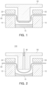
- FIG. 1 schematically illustrates a pouch film forming apparatus generally used to form an accommodating portion in which an electrode assembly is accommodated.
- a pouch film is disposed between a stripper and a die, fixed at a constant pressure, and an upper punch is lowered to form a pouch of a desired size.
- the pouch film may not be able to withstand the stress caused by molding and may be torn. In particular, pinholes or cracks tend to commonly occur in a corner portion of the pouch film.
- the present disclosure has been devised in view of the above circumstances, and an aspect of the present disclosure is to provide a press forming apparatus capable of manufacturing pouches for secondary batteries having various shapes, as well as preventing a bent portion of the pouch film from being intensively stretched when forming a pouch film.
- a press forming apparatus includes: a die in which a molded portion is formed by being recessed inwardly from an upper surface thereof; a stripper for fixing an object to be formed disposed on the die; a punch provided above the die to be movable upwardly and downwardly, and inserted into the molded portion when descending, to form an accommodating portion in the object to be formed, wherein a surface of the molded portion, in contact with the object to be formed, is curved, and the punch includes a vent for blowing air onto an upper surface of the object to be formed.
- a press forming apparatus includes: a die in which a molded portion is formed by being recessed inwardly from an upper surface thereof; a stripper for fixing the object to be formed disposed on the die; and a punch provided above the die to be movable upwardly and downwardly, and inserted into the molded portion when descending, to form an electrode assembly accommodating portion in the object to be formed, wherein a surface of the molded portion, in contact with the object to be formed, has a polygonal shape, and the punch includes a vent for blowing air onto an upper surface of the object to be formed.
- the air may be blown at a pressure of 0.1 to 10MPa.
- the vent may have a diameter of 1 to 100 mm.
- the vent may be formed by penetrating through a central portion of a punch inserted into the molded portion.
- the press forming apparatus may include a plurality of vents.
- the molded portion of the die may further include an inlet for intaking air.
- the molded portion of the die may include at least one selected from a group consisting of a silicone-based resin and a urethane-based resin.
- the object to be formed may be a pouch film for a secondary battery exterior material.
- FIG. 2 schematically illustrates a press forming apparatus according to an embodiment of the present disclosure
- FIG. 3 schematically illustrates a press forming apparatus according to another embodiment of the present disclosure.
- the present disclosure will be described in more detail with reference to FIGS. 2 and 3 .
- a press forming apparatus 100 comprising a die 10 in which a molded portion 15 is formed by being recessed inwardly from an upper surface thereof; a stripper 20 for fixing an object to be formed 50 disposed on the die 10; and a punch 30 provided above the die 10 to be movable upwardly and downwardly and inserted into the molded portion 15 when descending, to form an accommodating portion in the object to be formed 50, wherein a surface of the molded portion 15, in contact with the object to be formed 50, has a curved shape, and the punch 30 comprises a vent 40 for blowing air onto an upper surface of the object to be formed 50, is provided.
- a press forming apparatus 200 comprising a die 10 in which a molded portion 15 is recessed inwardly from an upper surface thereof; a stripper 20 for fixing an object to be formed 50 disposed on the die 10; and a punch 30 provided above the die 10 to be movable upwardly and downwardly and inserted into the molded portion 15 when descending, to form an electrode assembly accommodating portion in the object to be formed 50, wherein a surface of the molded portion 15, in contact with the object to be formed 50, has a polygonal shape, and the punch 30 comprises a vent 40 for blowing air onto an upper surface of the object to be formed 50, is provided.
- the press forming apparatus of the present disclosure may be used to form the object to be formed 50 of various materials in various shapes depending on the use, and the type of the object to be formed 50 is not particularly limited.
- the object to be formed 50 may be a pouch film used as an exterior material for secondary batteries.
- the pouch film includes a gas barrier layer, a surface protection layer, and a sealant layer.
- the gas barrier layer is intended to block gas ingress, and may include metal and an aluminum thin film (Al Foil) may be mainly used.
- the surface protection layer is positioned as an outermost layer to protect the electrode assembly from friction and collision with the outside, and a polymer such as a nylon resin or PET having mainly abrasion resistance and heat resistance may be used.
- the sealant layer is positioned in an innermost layer to directly be in contact with the electrode assembly, and a polymer such as polypropylene (PP) may be mainly used.
- PP polypropylene
- the die 10 is disposed below the object to be formed 50, and the die 10 may have a recessed molded portion 15 formed in a shape of a groove.
- the stripper 20 may serve to fix the object to be formed 50 by applying a predetermined pressure to the object to be formed 50 disposed on the die 10.
- a predetermined pressure to the object to be formed 50 disposed on the die 10.
- a punch 30 may be provided above the die 10 to be movable upwardly and downwardly, descend and be inserted into the molded portion 15 to form an accommodating portion in the object to be formed 50, and the punch 30 may include a vent 40 for blowing air onto an upper surface of the object to be formed 50.
- the pouch film may be uniformly stretched to a corner and a vertex portion connecting a bottom surface and an inner wall surface of the forming 15 or a corner portion in which an inner wall surface and an outer side surface thereof are connected, to mold an accommodating portion, and accordingly, the object to be formed 50 may be stably stretched, so that occurrence of cracks may be prevented when the punch 30 forms the object to be formed 50.
- the vent 40 may be formed by penetrating from an upper surface to a lower surface of the punch 30 inserted into the molded portion 15. Meanwhile, the position in which the vent 40 is formed is not particularly limited, but in order to apply a uniform pressure to the object to be formed 50 as a whole, the vent 40 is preferably formed by penetrating through a central portion of the punch 30 inserted into the molded portion 15.
- the press forming apparatus of the present disclosure may include a plurality of vents 40.
- the vent 40 may be formed in plural by penetrating the lower surface from the upper surface of the punch 30 so as to spray air toward a central portion and both end portions of the upper surface of the pouch film.
- the object to be formed 50 may be stretched more quickly and uniformly
- the air from the vent 40 is preferably blown at a pressure of 0.1 to 10 Mpa.
- a pressure of 0.1 to 10 Mpa When the pressure thereof is less than 0.1 Mpa, an effect of blowing may be reduced and there may be no stretching effect of the pouch, and when the pressure thereof exceeds 10Mpa, depending on excessive blowing, the pouch may be excessively stretched, there is a concern that the pouch may be torn or the quality thereof deteriorated, due to microcracks.
- a diameter of the vent 40 is preferably 1 to 100 mm.
- the diameter thereof is less than 1 mm, there is a problem in that a stretching effect of the pouch is insignificant due to insufficient air inflow into the punch.
- the diameter thereof exceeds 100 mm, an inflow of air into the punch is excessively increased, so that there may be a problem in that the pouch may be torn due to excessive stretching of the pouch, or the quality of the pouch may be deteriorated due to microcracks.
- a surface of the molded portion 15 of the die 10, in contact with the object to be formed 50 may have a curved shape or polygonal shape. Accordingly, an elongation of a corner portion of a pouch in which a secondary battery is accommodated, so that a thicker cell can be manufactured.
- the punch due to the punch, it is possible to prevent the deterioration of the quality due to an appearance defect occurring in the pouch such as scratches, wrinkles, scratches and cracks, there is an advantage in that the punch design is easy to improve the defect.
- pouches having various appearances may be manufactured according to the shape of the surface of the molded portion 15 of the die 10, in contact with the object to be formed 50.
- the press forming apparatus of the present disclosure may be made of a metal material such as stainless steel, and according to an embodiment of the present disclosure, the molded portion 15 of the die 10 may include a silicone-based or urethane-based resin.
- a silicone-based or urethane-based resin By forming the molded portion 15 of the die 10 with a soft silicone-based or urethane-based resin, it is possible to more significantly reduce appearance defects such as scratches, wrinkles, scratches and cracks occurring in the pouch.
- An inlet for intaking air may be additionally formed in the molded portion 15 of the die 10. As described above, when the object to be formed 50 is formed with the punch 30, after stretching the object to be formed 50 by air from the vent 40, the inlet may quickly intake and remove air between the punch 30 and the molded portion 15, and accordingly, the punch 30 may be in close contact with the molded portion 15, so that the pouch film may be formed more precisely.
- a secondary battery including a pouch film formed by the above-described press forming apparatus and an electrode assembly accommodated in the pouch film.
- the electrode assembly includes a positive electrode, a negative electrode, and a separator included between the positive electrode and the negative electrode, and any positive electrode, negative electrode, and separator known in the art may be used as the positive electrode, negative electrode, and separator.
- the positive electrode may include a positive electrode mixture layer formed on a positive electrode current collector.
- the positive electrode current collector is not particularly limited, but a thin plate made of aluminum, stainless steel, or nickel may be used, and it is preferable to use a thin plate made of aluminum.
- a porous body such as a net-shaped type or mesh-shaped type may be used, and may be coated with an oxidation-resistant metal or alloy film to prevent oxidation.
- the positive electrode mixture layer may include a positive electrode active material, a binder, and a conductive material, and the positive electrode active material is a compound capable of reversible intercalation and deintercalation of lithium, and may include a lithium transition metal composite oxide containing at least one transition metal consisting of nickel, cobalt, manganese and aluminum, and lithium, and preferably, a lithium transition metal composite oxide containing transition metal containing nickel, cobalt, and manganese, and lithium.
- a binder may be additionally included in order to improve binding of an active material, a conductive material, and the like, and adhesion to a current collector, it may include for example, at least one of polyvinylidene fluoride, polyvinyl alcohol, carboxymethyl cellulose (CMC), starch, hydroxypropylcellulose, regenerated cellulose, polyvinylpyrrolidone, tetrafluoroethylene, polyethylene, polypropylene, ethylene-propylene-diene terpolymer (EPDM), sulfonated EPDM, styrene-butadiene rubber and fluororubber, and preferably, polyvinylidene fluoride.
- CMC carboxymethyl cellulose
- EPDM ethylene-propylene-diene terpolymer
- EPDM ethylene-propylene-diene terpolymer
- EPDM ethylene-propylene-diene terpolymer
- EPDM ethylene-propylene-diene terpol
- the conductive material for improving conductivity may be at least one selected from a group consisting of graphite, carbon black, carbon nanotubes, metal powder, and conductive oxides.
- the negative electrode may include a negative electrode mixture layer formed on a negative electrode current collector.
- a negative electrode current collector copper, stainless steel, aluminum, nickel, titanium, calcined carbon, one in which a surface of copper or stainless steel is surface-treated with carbon, nickel, titanium, silver (but is not limited thereto), an aluminum-cadmium alloy, may be used, but is not limited thereto.
- bonding strength of the negative electrode active material may be strengthened by forming fine irregularities on a surface thereof, and may be used in various forms such as a film, sheet, foil, net, porous body, foam, non-woven body.
- the negative active material may be a silicon-based negative active material and/or a carbon-based negative active material.
- the silicon-based negative active material may be at least any one selected from a group consisting of SiOx (0 ⁇ x ⁇ 2) particles, a Si-C composite, and a Si-Y alloy (where Y is an alkali metal, alkaline earth metal, transition metal, group 13 element, group 14 elements, rare earth elements, and combinations thereof), and for example, SiO.
- the carbon-based negative active material may be, for example, at least one selected from a group consisting of artificial graphite, natural graphite, and graphitized mesocarbon microbeads, and is preferably artificial graphite.
- the negative electrode mixture layer may also include a binder and a conductive material.
- the binder may include an aqueous binder and a rubber-based binder, and the aqueous binder may be dissolved in an aqueous solvent such as water, and may include at least one selected from a group consisting of polyvinyl alcohol (PVA), polyacrylic acid (PAA), polyethylene glycol (PEG), polyacrylonitrile (PAN) and polyacryl amide (PAM), and carboxylmethyl cellulose (CMC).
- PVA polyvinyl alcohol
- PAA polyacrylic acid
- PEG polyethylene glycol
- PAN polyacrylonitrile
- PAM polyacryl amide
- CMC carboxylmethyl cellulose
- the rubber-based binder does not dissolve well in aqueous solvents such as water, but may be defined as being able to be smoothly dispersed in an aqueous solvent.
- the rubber-based binder may include at least one selected from styrene butadiene rubber (SBR), hydrogenated nitrile butadiene rubber (HNBR), acrylonitrile butadiene rubber, acrylic rubber, butyl rubber, and fluoro rubber, and preferably, include at least one selected from a group consisting of styrene-butadiene rubber and hydrogenated nitrile-butadiene rubber, more preferably styrene-butadiene rubber, in terms of easy dispersion and excellent phase stability.
- SBR styrene butadiene rubber
- HNBR hydrogenated nitrile butadiene rubber
- acrylonitrile butadiene rubber acrylic rubber
- butyl rubber butyl rubber
- fluoro rubber preferably, include at least one selected from a group consisting of styrene-butadiene rubber and hydrogenated nitrile-butadiene rubber, more preferably styrene-butad
- the conductive material may be at least one selected from a group consisting of graphite, carbon black, carbon nanotubes, metal powder, and conductive oxides.
- a porous polymer film for example, a porous polymer film made of a polyolefin-based polymer such as an ethylene homopolymer, a propylene homopolymer, an ethylene/butene copolymer, an ethylene/hexene copolymer, an ethylene/methacrylate copolymer, may be used alone or by laminating thereof, or a nonwoven fabric, for example, a high melting point glass fiber, a nonwoven fabric made of polyethylene terephthalate fiber, may be used, but is not limited thereto.
- a nonwoven fabric for example, a high melting point glass fiber, a nonwoven fabric made of polyethylene terephthalate fiber, may be used, but is not limited thereto.
- the present disclosure relates also to the following numbered aspects:
- a molded portion of a pouch film may be uniformly elongated, thereby preventing cracks, or the like from occurring, and furthermore, long-term reliability of the secondary battery, thereby improving workability and productivity, and furthermore, long-term reliability of the secondary battery may be secured.
Landscapes
- Engineering & Computer Science (AREA)
- Mechanical Engineering (AREA)
- Chemical & Material Sciences (AREA)
- Chemical Kinetics & Catalysis (AREA)
- Electrochemistry (AREA)
- General Chemical & Material Sciences (AREA)
- Manufacturing & Machinery (AREA)
- Sealing Battery Cases Or Jackets (AREA)
Abstract
Description
- The present disclosure relates to a press forming apparatus, and preferably to a press forming apparatus used for forming a pouch film for a secondary battery.
- Unlike a primary battery that cannot be charged, a secondary battery that can be charged and discharged is widely used in small, high tech electronic devices such as mobile phones, PDAs, notebook computers, and the like, as well as mid-to-large devices such as electric vehicles, in recent years.
- Such a secondary battery may be classified as a cylindrical secondary battery, a prismatic secondary battery, a pouch-type secondary battery, or the like, depending on the structure and manufacturing method thereof. Thereamong, the pouch-type secondary battery is manufactured by accommodating an electrode assembly in a pouch-type sheet and then sealing the sheet, and the pouch-type secondary battery has a simple structure and high capacitance per unit volume, compared to other types of secondary batteries, so it is widely used in automobile batteries, energy storage devices, or the like.
- The pouch-type secondary battery includes an electrode assembly, an electrode lead coupled to the electrode assembly, and a pouch accommodating the electrode assembly with a tip of the electrode lead led out therefrom. More specifically, in the pouch-type secondary battery, an accommodating portion having a recessed shape is formed in a pouch-type sheet, and then an electrode assembly is accommodated in the accommodating portion, and the pouch-type sheet is folded so that one region of the pouch-type sheet covers the electrode assembly, and then a sealing portion sealing a periphery of the electrode assembly is formed, to manufacture the pouch-type secondary battery. The sealing portion generally has a shape protruding outwardly.
-
FIG. 1 schematically illustrates a pouch film forming apparatus generally used to form an accommodating portion in which an electrode assembly is accommodated. Referring toFIG. 1 , a pouch film is disposed between a stripper and a die, fixed at a constant pressure, and an upper punch is lowered to form a pouch of a desired size. As described above, in the case of reaching a limit of ductility of a material of the pouch film in a process of forming by applying force to the pouch film, the pouch film may not be able to withstand the stress caused by molding and may be torn. In particular, pinholes or cracks tend to commonly occur in a corner portion of the pouch film. - Accordingly, there may be a problem in workability and productivity when forming the pouch film, and also, as elongation is decreased, there may be a problem in the long-term reliability of the pouch-type battery.
- The present disclosure has been devised in view of the above circumstances, and an aspect of the present disclosure is to provide a press forming apparatus capable of manufacturing pouches for secondary batteries having various shapes, as well as preventing a bent portion of the pouch film from being intensively stretched when forming a pouch film.
- According to an aspect of the present disclosure, a press forming apparatus, includes: a die in which a molded portion is formed by being recessed inwardly from an upper surface thereof; a stripper for fixing an object to be formed disposed on the die; a punch provided above the die to be movable upwardly and downwardly, and inserted into the molded portion when descending, to form an accommodating portion in the object to be formed, wherein a surface of the molded portion, in contact with the object to be formed, is curved, and the punch includes a vent for blowing air onto an upper surface of the object to be formed.
- According to an aspect of the present disclosure, a press forming apparatus, includes: a die in which a molded portion is formed by being recessed inwardly from an upper surface thereof; a stripper for fixing the object to be formed disposed on the die; and a punch provided above the die to be movable upwardly and downwardly, and inserted into the molded portion when descending, to form an electrode assembly accommodating portion in the object to be formed, wherein a surface of the molded portion, in contact with the object to be formed, has a polygonal shape, and the punch includes a vent for blowing air onto an upper surface of the object to be formed.
- The air may be blown at a pressure of 0.1 to 10MPa.
- The vent may have a diameter of 1 to 100 mm.
- The vent may be formed by penetrating through a central portion of a punch inserted into the molded portion.
- The press forming apparatus may include a plurality of vents.
- The molded portion of the die may further include an inlet for intaking air.
- The molded portion of the die may include at least one selected from a group consisting of a silicone-based resin and a urethane-based resin.
- The object to be formed may be a pouch film for a secondary battery exterior material.
- The above and other aspects, features, and advantages of the present disclosure will be more clearly understood from the following detailed description, taken in conjunction with the accompanying drawings, in which:
-
FIG. 1 schematically illustrates a pouch film forming apparatus generally used to form an accommodating portion in which an electrode assembly is accommodated. -
FIG. 2 schematically illustrates a press forming apparatus according to an embodiment of the present disclosure. -
FIG. 3 schematically illustrates a press forming apparatus according to another embodiment of the present disclosure. - The present disclosure relates to a press forming apparatus, and
FIG. 2 schematically illustrates a press forming apparatus according to an embodiment of the present disclosure, andFIG. 3 schematically illustrates a press forming apparatus according to another embodiment of the present disclosure. Hereinafter, the present disclosure will be described in more detail with reference toFIGS. 2 and3 . - According to an aspect of the present disclosure, a
press forming apparatus 100 comprising adie 10 in which a moldedportion 15 is formed by being recessed inwardly from an upper surface thereof; astripper 20 for fixing an object to be formed 50 disposed on thedie 10; and apunch 30 provided above thedie 10 to be movable upwardly and downwardly and inserted into the moldedportion 15 when descending, to form an accommodating portion in the object to be formed 50, wherein a surface of the moldedportion 15, in contact with the object to be formed 50, has a curved shape, and thepunch 30 comprises avent 40 for blowing air onto an upper surface of the object to be formed 50, is provided. - According to another aspect of the present disclosure, a
press forming apparatus 200 comprising adie 10 in which a moldedportion 15 is recessed inwardly from an upper surface thereof; astripper 20 for fixing an object to be formed 50 disposed on thedie 10; and apunch 30 provided above thedie 10 to be movable upwardly and downwardly and inserted into the moldedportion 15 when descending, to form an electrode assembly accommodating portion in the object to be formed 50, wherein a surface of themolded portion 15, in contact with the object to be formed 50, has a polygonal shape, and thepunch 30 comprises avent 40 for blowing air onto an upper surface of the object to be formed 50, is provided. - The press forming apparatus of the present disclosure may be used to form the object to be formed 50 of various materials in various shapes depending on the use, and the type of the object to be formed 50 is not particularly limited. As an example, the object to be formed 50 may be a pouch film used as an exterior material for secondary batteries. Although not particularly limited, the pouch film includes a gas barrier layer, a surface protection layer, and a sealant layer. The gas barrier layer is intended to block gas ingress, and may include metal and an aluminum thin film (Al Foil) may be mainly used. The surface protection layer is positioned as an outermost layer to protect the electrode assembly from friction and collision with the outside, and a polymer such as a nylon resin or PET having mainly abrasion resistance and heat resistance may be used. The sealant layer is positioned in an innermost layer to directly be in contact with the electrode assembly, and a polymer such as polypropylene (PP) may be mainly used.
- In the press forming apparatus of the present disclosure, the die 10 is disposed below the object to be formed 50, and the die 10 may have a recessed molded
portion 15 formed in a shape of a groove. - The
stripper 20 may serve to fix the object to be formed 50 by applying a predetermined pressure to the object to be formed 50 disposed on the die 10. When thepunch 30 is applied to the object to be formed 50, if the pressure applied to thestripper 20 is excessive, damage such as the object to be formed 50 being torn may occur, in consideration thereof, the pressure applied to thestripper 20 is preferably controlled appropriately. - A
punch 30 may be provided above thedie 10 to be movable upwardly and downwardly, descend and be inserted into the moldedportion 15 to form an accommodating portion in the object to be formed 50, and thepunch 30 may include avent 40 for blowing air onto an upper surface of the object to be formed 50. - As the
vent 40 descends, air is blown onto an upper surface of the object to be formed 50 to form a predetermined air pocket at an interface of the object to be formed 50, and by pressure of the air, an entirety of the object to be formed 50 positioned on the moldedportion 15 is uniformly stretched in a downward direction and is in close contact with an inner surface of the moldedportion 15, and in particular, as illustrated by a hatched portion of the object to be formed 50 ofFIG. 2 , the pouch film may be uniformly stretched to a corner and a vertex portion connecting a bottom surface and an inner wall surface of the forming 15 or a corner portion in which an inner wall surface and an outer side surface thereof are connected, to mold an accommodating portion, and accordingly, the object to be formed 50 may be stably stretched, so that occurrence of cracks may be prevented when thepunch 30 forms the object to be formed 50. - The
vent 40 may be formed by penetrating from an upper surface to a lower surface of thepunch 30 inserted into the moldedportion 15. Meanwhile, the position in which thevent 40 is formed is not particularly limited, but in order to apply a uniform pressure to the object to be formed 50 as a whole, thevent 40 is preferably formed by penetrating through a central portion of thepunch 30 inserted into the moldedportion 15. - According to another embodiment of the present disclosure, the press forming apparatus of the present disclosure may include a plurality of
vents 40. For example, thevent 40 may be formed in plural by penetrating the lower surface from the upper surface of thepunch 30 so as to spray air toward a central portion and both end portions of the upper surface of the pouch film. By including the plurality ofvents 40, the object to be formed 50 may be stretched more quickly and uniformly - Meanwhile, the air from the
vent 40 is preferably blown at a pressure of 0.1 to 10 Mpa. When the pressure thereof is less than 0.1 Mpa, an effect of blowing may be reduced and there may be no stretching effect of the pouch, and when the pressure thereof exceeds 10Mpa, depending on excessive blowing, the pouch may be excessively stretched, there is a concern that the pouch may be torn or the quality thereof deteriorated, due to microcracks. - Although not particularly limited, a diameter of the
vent 40 is preferably 1 to 100 mm. When the diameter thereof is less than 1 mm, there is a problem in that a stretching effect of the pouch is insignificant due to insufficient air inflow into the punch. On the other hand, when the diameter thereof exceeds 100 mm, an inflow of air into the punch is excessively increased, so that there may be a problem in that the pouch may be torn due to excessive stretching of the pouch, or the quality of the pouch may be deteriorated due to microcracks. - Meanwhile, a surface of the molded
portion 15 of thedie 10, in contact with the object to be formed 50, may have a curved shape or polygonal shape. Accordingly, an elongation of a corner portion of a pouch in which a secondary battery is accommodated, so that a thicker cell can be manufactured. In addition, due to the punch, it is possible to prevent the deterioration of the quality due to an appearance defect occurring in the pouch such as scratches, wrinkles, scratches and cracks, there is an advantage in that the punch design is easy to improve the defect. Furthermore, according to the shape of the surface of the moldedportion 15 of thedie 10, in contact with the object to be formed 50, pouches having various appearances may be manufactured. - Meanwhile, the press forming apparatus of the present disclosure may be made of a metal material such as stainless steel, and according to an embodiment of the present disclosure, the
molded portion 15 of the die 10 may include a silicone-based or urethane-based resin. By forming themolded portion 15 of thedie 10 with a soft silicone-based or urethane-based resin, it is possible to more significantly reduce appearance defects such as scratches, wrinkles, scratches and cracks occurring in the pouch. - An inlet for intaking air may be additionally formed in the molded
portion 15 of the die 10. As described above, when the object to be formed 50 is formed with thepunch 30, after stretching the object to be formed 50 by air from thevent 40, the inlet may quickly intake and remove air between thepunch 30 and themolded portion 15, and accordingly, thepunch 30 may be in close contact with the moldedportion 15, so that the pouch film may be formed more precisely. - According to another aspect of the present disclosure, a secondary battery including a pouch film formed by the above-described press forming apparatus and an electrode assembly accommodated in the pouch film.
- The electrode assembly includes a positive electrode, a negative electrode, and a separator included between the positive electrode and the negative electrode, and any positive electrode, negative electrode, and separator known in the art may be used as the positive electrode, negative electrode, and separator.
- For example, the positive electrode may include a positive electrode mixture layer formed on a positive electrode current collector. The positive electrode current collector is not particularly limited, but a thin plate made of aluminum, stainless steel, or nickel may be used, and it is preferable to use a thin plate made of aluminum. In addition, a porous body such as a net-shaped type or mesh-shaped type may be used, and may be coated with an oxidation-resistant metal or alloy film to prevent oxidation.
- The positive electrode mixture layer may include a positive electrode active material, a binder, and a conductive material, and the positive electrode active material is a compound capable of reversible intercalation and deintercalation of lithium, and may include a lithium transition metal composite oxide containing at least one transition metal consisting of nickel, cobalt, manganese and aluminum, and lithium, and preferably, a lithium transition metal composite oxide containing transition metal containing nickel, cobalt, and manganese, and lithium.
- A binder may be additionally included in order to improve binding of an active material, a conductive material, and the like, and adhesion to a current collector, it may include for example, at least one of polyvinylidene fluoride, polyvinyl alcohol, carboxymethyl cellulose (CMC), starch, hydroxypropylcellulose, regenerated cellulose, polyvinylpyrrolidone, tetrafluoroethylene, polyethylene, polypropylene, ethylene-propylene-diene terpolymer (EPDM), sulfonated EPDM, styrene-butadiene rubber and fluororubber, and preferably, polyvinylidene fluoride.
- The conductive material for improving conductivity may be at least one selected from a group consisting of graphite, carbon black, carbon nanotubes, metal powder, and conductive oxides.
- The negative electrode may include a negative electrode mixture layer formed on a negative electrode current collector. As the negative electrode current collector, copper, stainless steel, aluminum, nickel, titanium, calcined carbon, one in which a surface of copper or stainless steel is surface-treated with carbon, nickel, titanium, silver (but is not limited thereto), an aluminum-cadmium alloy, may be used, but is not limited thereto. In addition, like the positive electrode current collector, bonding strength of the negative electrode active material may be strengthened by forming fine irregularities on a surface thereof, and may be used in various forms such as a film, sheet, foil, net, porous body, foam, non-woven body.
- The negative active material may be a silicon-based negative active material and/or a carbon-based negative active material. Although not particularly limited, the silicon-based negative active material may be at least any one selected from a group consisting of SiOx (0≤x<2) particles, a Si-C composite, and a Si-Y alloy (where Y is an alkali metal, alkaline earth metal, transition metal, group 13 element, group 14 elements, rare earth elements, and combinations thereof), and for example, SiO. The carbon-based negative active material may be, for example, at least one selected from a group consisting of artificial graphite, natural graphite, and graphitized mesocarbon microbeads, and is preferably artificial graphite.
- The negative electrode mixture layer may also include a binder and a conductive material. The binder may include an aqueous binder and a rubber-based binder, and the aqueous binder may be dissolved in an aqueous solvent such as water, and may include at least one selected from a group consisting of polyvinyl alcohol (PVA), polyacrylic acid (PAA), polyethylene glycol (PEG), polyacrylonitrile (PAN) and polyacryl amide (PAM), and carboxylmethyl cellulose (CMC). The rubber-based binder does not dissolve well in aqueous solvents such as water, but may be defined as being able to be smoothly dispersed in an aqueous solvent. Specifically, the rubber-based binder may include at least one selected from styrene butadiene rubber (SBR), hydrogenated nitrile butadiene rubber (HNBR), acrylonitrile butadiene rubber, acrylic rubber, butyl rubber, and fluoro rubber, and preferably, include at least one selected from a group consisting of styrene-butadiene rubber and hydrogenated nitrile-butadiene rubber, more preferably styrene-butadiene rubber, in terms of easy dispersion and excellent phase stability.
- In addition, the conductive material may be at least one selected from a group consisting of graphite, carbon black, carbon nanotubes, metal powder, and conductive oxides.
- In addition, as a separator, a porous polymer film, for example, a porous polymer film made of a polyolefin-based polymer such as an ethylene homopolymer, a propylene homopolymer, an ethylene/butene copolymer, an ethylene/hexene copolymer, an ethylene/methacrylate copolymer, may be used alone or by laminating thereof, or a nonwoven fabric, for example, a high melting point glass fiber, a nonwoven fabric made of polyethylene terephthalate fiber, may be used, but is not limited thereto.
- The present disclosure relates also to the following numbered aspects:
- Aspect 1: A press forming apparatus, comprising: a die in which a molded portion is formed by being recessed inwardly from an upper surface thereof; a stripper for fixing an object to be formed disposed on the die; a punch provided above the die to be movable upwardly and downwardly, and inserted into the molded portion when descending, to form an accommodating portion in the object to be formed, wherein a surface of the molded portion, in contact with the object to be formed, is curved, and the punch includes a vent for blowing air onto an upper surface of the object to be formed.
- Aspect 2: A press forming apparatus, comprising: a die in which a molded portion is formed by being recessed inwardly from an upper surface thereof; a stripper for fixing the object to be formed disposed on the die; and a punch provided above the die to be movable upwardly and downwardly, and inserted into the molded portion when descending, to form an electrode assembly accommodating portion in the object to be formed, wherein a surface of the molded portion, in contact with the object to be formed, has a polygonal shape, and the punch includes a vent for blowing air onto an upper surface of the object to be formed.
- Aspect 3: The press forming apparatus of any of the preceding aspects, whrerein the air is blown at a pressure of 0.1 to 10Mpa.
- Aspect 4: The press forming apparatus of any of the preceding aspects, whrerein the vent has a diameter of 1 to 100mm.
- Aspect 5: The press forming apparatus of any of the preceding aspects, whrerein the vent is formed by penetrating through a central portion of the punch inserted into the molded portion.
- Aspect 6: The press forming apparatus of any of the preceding aspects, whrerein the vent is comprised in a plurality.
- Aspect 7: The press forming apparatus of any of the preceding aspects, whrerein the molded portion of the die further comprises an inlet for intaking air.
- Aspect 8: The press forming apparatus of any of the preceding aspects, whrerein the molded portion of the die comprises at least one selected from a group consisting of a silicone-based resin and a urethane-based resin.
- Aspect 9: The press forming apparatus of any of the preceding aspects, whrerein the object to be formed is a pouch film for a secondary battery exterior material.
- As set forth above, according to the present disclosure, a molded portion of a pouch film may be uniformly elongated, thereby preventing cracks, or the like from occurring, and furthermore, long-term reliability of the secondary battery, thereby improving workability and productivity, and furthermore, long-term reliability of the secondary battery may be secured.
- The examples described herein are to be considered in a descriptive sense only, and not for purposes of limitation. Descriptions of features or aspects in each example are to be considered as being applicable to similar features or aspects in other examples.
Claims (9)
- A press forming apparatus, comprising:a die in which a molded portion is formed by being recessed inwardly from an upper surface thereof;a stripper for fixing an object to be formed disposed on the die;a punch provided above the die to be movable upwardly and downwardly, and inserted into the molded portion when descending, to form an accommodating portion in the object to be formed,wherein a surface of the molded portion, in contact with the object to be formed, is curved, andthe punch comprises a vent for blowing air onto an upper surface of the object to be formed.
- A press forming apparatus, comprising:a die in which a molded portion is formed by being recessed inwardly from an upper surface thereof;a stripper for fixing the object to be formed disposed on the die; anda punch provided above the die to be movable upwardly and downwardly, and inserted into the molded portion when descending, to form an electrode assembly accommodating portion in the object to be formed,wherein a surface of the molded portion, in contact with the object to be formed, has a polygonal shape, andthe punch comprises a vent for blowing air onto an upper surface of the object to be formed.
- The press forming apparatus of any of claims 1 or 2, wherein the air is blown at a pressure of 0.1 to 10Mpa.
- The press forming apparatus of any of claims 1 to 3, wherein the vent has a diameter of 1 to 100mm.
- The press forming apparatus of any of claims 1 to 4, wherein the vent is formed by penetrating through a central portion of the punch inserted into the molded portion.
- The press forming apparatus of any of claims 1 to 5, wherein the vent is comprised in a plurality.
- The press forming apparatus of any of claims 1 to 6, wherein the molded portion of the die further comprises an inlet for intaking air.
- The press forming apparatus of any of claims 1 to 7, wherein the molded portion of the die comprises at least one selected from a group consisting of a silicone-based resin and a urethane-based resin.
- The press forming apparatus of any of claims 1 to 8, wherein the object to be formed is a pouch film for a secondary battery exterior material.
Applications Claiming Priority (1)
| Application Number | Priority Date | Filing Date | Title |
|---|---|---|---|
| KR1020210176475A KR20230087864A (en) | 2021-12-10 | 2021-12-10 | Apparatus for press forming |
Publications (1)
| Publication Number | Publication Date |
|---|---|
| EP4194175A1 true EP4194175A1 (en) | 2023-06-14 |
Family
ID=84361370
Family Applications (1)
| Application Number | Title | Priority Date | Filing Date |
|---|---|---|---|
| EP22205177.3A Pending EP4194175A1 (en) | 2021-12-10 | 2022-11-02 | Apparatus for press forming |
Country Status (4)
| Country | Link |
|---|---|
| US (1) | US20230182354A1 (en) |
| EP (1) | EP4194175A1 (en) |
| KR (1) | KR20230087864A (en) |
| CN (1) | CN116251889A (en) |
Families Citing this family (2)
| Publication number | Priority date | Publication date | Assignee | Title |
|---|---|---|---|---|
| US20240051195A1 (en) * | 2021-12-23 | 2024-02-15 | Arris Composites Inc. | Apparatus and Method for Controlling the Alignment of Fiber Loops in Compression Molded Articles |
| WO2025084752A1 (en) * | 2023-10-17 | 2025-04-24 | 주식회사 엘지에너지솔루션 | Molding apparatus and molding method, and pouch-type battery case manufactured thereby |
Citations (5)
| Publication number | Priority date | Publication date | Assignee | Title |
|---|---|---|---|---|
| KR101073870B1 (en) * | 2010-07-13 | 2011-10-14 | (주)열린기술 | Secondary battery case manufacturing method |
| US20180243966A1 (en) * | 2016-04-15 | 2018-08-30 | Lg Chem, Ltd. | Apparatus and method for forming pouch case for secondary battery |
| KR20180134133A (en) * | 2017-06-08 | 2018-12-18 | 주식회사 엘지화학 | Forming apparatus and method for secondary battery |
| US20200168853A1 (en) * | 2018-11-23 | 2020-05-28 | Lg Chem, Ltd. | Pouch forming device and method and facility for producing secondary battery comprising the pouch forming device |
| KR20200075989A (en) * | 2018-12-18 | 2020-06-29 | 주식회사 엘지화학 | The Battery Case, The Secondary Battery And The Method For Manufacturing Thereof |
-
2021
- 2021-12-10 KR KR1020210176475A patent/KR20230087864A/en active Pending
-
2022
- 2022-10-31 CN CN202211365646.0A patent/CN116251889A/en active Pending
- 2022-11-02 US US17/979,093 patent/US20230182354A1/en active Pending
- 2022-11-02 EP EP22205177.3A patent/EP4194175A1/en active Pending
Patent Citations (5)
| Publication number | Priority date | Publication date | Assignee | Title |
|---|---|---|---|---|
| KR101073870B1 (en) * | 2010-07-13 | 2011-10-14 | (주)열린기술 | Secondary battery case manufacturing method |
| US20180243966A1 (en) * | 2016-04-15 | 2018-08-30 | Lg Chem, Ltd. | Apparatus and method for forming pouch case for secondary battery |
| KR20180134133A (en) * | 2017-06-08 | 2018-12-18 | 주식회사 엘지화학 | Forming apparatus and method for secondary battery |
| US20200168853A1 (en) * | 2018-11-23 | 2020-05-28 | Lg Chem, Ltd. | Pouch forming device and method and facility for producing secondary battery comprising the pouch forming device |
| KR20200075989A (en) * | 2018-12-18 | 2020-06-29 | 주식회사 엘지화학 | The Battery Case, The Secondary Battery And The Method For Manufacturing Thereof |
Also Published As
| Publication number | Publication date |
|---|---|
| KR20230087864A (en) | 2023-06-19 |
| US20230182354A1 (en) | 2023-06-15 |
| CN116251889A (en) | 2023-06-13 |
Similar Documents
| Publication | Publication Date | Title |
|---|---|---|
| US9755213B2 (en) | Cathode including insulation layer on cathode tab and secondary battery including the cathode | |
| US11502382B2 (en) | Nonaqueous electrolyte secondary battery | |
| US20230182354A1 (en) | Apparatus for press forming | |
| CN117638254B (en) | Electrode assembly and battery | |
| US20190097228A1 (en) | Nonaqueous electrolyte secondary battery | |
| CN105340118B (en) | Roll-type electrode assembly and secondary battery comprising same | |
| US10673059B2 (en) | Method for manufacturing electrode and method for manufacturing secondary battery | |
| US20230080725A1 (en) | Secondary Battery and Method of Manufacturing the Same | |
| US12308471B2 (en) | Separator having no separator substrate and electrochemical device including the same | |
| KR102158089B1 (en) | Cylindrical battery can, secondary battery comprising the same and fabricating methods thereof | |
| CN117730454A (en) | Separator for electrochemical device and electrochemical device containing same | |
| WO2025102387A1 (en) | Battery cell, battery and electric device | |
| CN221632702U (en) | Housing, battery cells, batteries and electrical equipment | |
| US20230291078A1 (en) | Battery | |
| US10468667B2 (en) | Electrode sheet for use in power storage device and power storage device including electrode sheet | |
| CN221632713U (en) | Battery cells, batteries and electrical equipment | |
| CN221668940U (en) | Battery monomer, battery and electric equipment | |
| CN221668941U (en) | Battery monomer, battery and electric equipment | |
| CN221885216U (en) | Casing, battery cell, battery and electrical device | |
| KR20160024685A (en) | Lithium secondary battery having side bead | |
| WO2025102389A1 (en) | Battery cell, battery, and electrical device | |
| WO2025102388A1 (en) | Battery cell, battery and electric device | |
| CN118281151A (en) | Battery positive pole piece and battery thereof | |
| CN208028134U (en) | a membrane structure | |
| CN221632703U (en) | Battery cells, batteries and electrical equipment |
Legal Events
| Date | Code | Title | Description |
|---|---|---|---|
| PUAI | Public reference made under article 153(3) epc to a published international application that has entered the european phase |
Free format text: ORIGINAL CODE: 0009012 |
|
| STAA | Information on the status of an ep patent application or granted ep patent |
Free format text: STATUS: THE APPLICATION HAS BEEN PUBLISHED |
|
| AK | Designated contracting states |
Kind code of ref document: A1 Designated state(s): AL AT BE BG CH CY CZ DE DK EE ES FI FR GB GR HR HU IE IS IT LI LT LU LV MC ME MK MT NL NO PL PT RO RS SE SI SK SM TR |
|
| STAA | Information on the status of an ep patent application or granted ep patent |
Free format text: STATUS: REQUEST FOR EXAMINATION WAS MADE |
|
| 17P | Request for examination filed |
Effective date: 20231213 |
|
| RBV | Designated contracting states (corrected) |
Designated state(s): AL AT BE BG CH CY CZ DE DK EE ES FI FR GB GR HR HU IE IS IT LI LT LU LV MC ME MK MT NL NO PL PT RO RS SE SI SK SM TR |