EP4194158A1 - Scalable area gripper, system, and method for a material handling process for composite manufacturing - Google Patents
Scalable area gripper, system, and method for a material handling process for composite manufacturing Download PDFInfo
- Publication number
- EP4194158A1 EP4194158A1 EP22203752.5A EP22203752A EP4194158A1 EP 4194158 A1 EP4194158 A1 EP 4194158A1 EP 22203752 A EP22203752 A EP 22203752A EP 4194158 A1 EP4194158 A1 EP 4194158A1
- Authority
- EP
- European Patent Office
- Prior art keywords
- vacuum
- see
- area gripper
- scalable area
- scalable
- Prior art date
- Legal status (The legal status is an assumption and is not a legal conclusion. Google has not performed a legal analysis and makes no representation as to the accuracy of the status listed.)
- Granted
Links
Images









Classifications
-
- B—PERFORMING OPERATIONS; TRANSPORTING
- B25—HAND TOOLS; PORTABLE POWER-DRIVEN TOOLS; MANIPULATORS
- B25J—MANIPULATORS; CHAMBERS PROVIDED WITH MANIPULATION DEVICES
- B25J15/00—Gripping heads and other end effectors
- B25J15/0052—Gripping heads and other end effectors multiple gripper units or multiple end effectors
- B25J15/0061—Gripping heads and other end effectors multiple gripper units or multiple end effectors mounted on a modular gripping structure
-
- B—PERFORMING OPERATIONS; TRANSPORTING
- B29—WORKING OF PLASTICS; WORKING OF SUBSTANCES IN A PLASTIC STATE IN GENERAL
- B29C—SHAPING OR JOINING OF PLASTICS; SHAPING OF MATERIAL IN A PLASTIC STATE, NOT OTHERWISE PROVIDED FOR; AFTER-TREATMENT OF THE SHAPED PRODUCTS, e.g. REPAIRING
- B29C70/00—Shaping composites, i.e. plastics material comprising reinforcements, fillers or preformed parts, e.g. inserts
- B29C70/04—Shaping composites, i.e. plastics material comprising reinforcements, fillers or preformed parts, e.g. inserts comprising reinforcements only, e.g. self-reinforcing plastics
- B29C70/28—Shaping operations therefor
- B29C70/30—Shaping by lay-up, i.e. applying fibres, tape or broadsheet on a mould, former or core; Shaping by spray-up, i.e. spraying of fibres on a mould, former or core
- B29C70/38—Automated lay-up, e.g. using robots, laying filaments according to predetermined patterns
-
- B—PERFORMING OPERATIONS; TRANSPORTING
- B25—HAND TOOLS; PORTABLE POWER-DRIVEN TOOLS; MANIPULATORS
- B25J—MANIPULATORS; CHAMBERS PROVIDED WITH MANIPULATION DEVICES
- B25J15/00—Gripping heads and other end effectors
- B25J15/06—Gripping heads and other end effectors with vacuum or magnetic holding means
- B25J15/0616—Gripping heads and other end effectors with vacuum or magnetic holding means with vacuum
- B25J15/0625—Gripping heads and other end effectors with vacuum or magnetic holding means with vacuum provided with a valve
-
- B—PERFORMING OPERATIONS; TRANSPORTING
- B29—WORKING OF PLASTICS; WORKING OF SUBSTANCES IN A PLASTIC STATE IN GENERAL
- B29C—SHAPING OR JOINING OF PLASTICS; SHAPING OF MATERIAL IN A PLASTIC STATE, NOT OTHERWISE PROVIDED FOR; AFTER-TREATMENT OF THE SHAPED PRODUCTS, e.g. REPAIRING
- B29C70/00—Shaping composites, i.e. plastics material comprising reinforcements, fillers or preformed parts, e.g. inserts
- B29C70/04—Shaping composites, i.e. plastics material comprising reinforcements, fillers or preformed parts, e.g. inserts comprising reinforcements only, e.g. self-reinforcing plastics
- B29C70/28—Shaping operations therefor
- B29C70/30—Shaping by lay-up, i.e. applying fibres, tape or broadsheet on a mould, former or core; Shaping by spray-up, i.e. spraying of fibres on a mould, former or core
- B29C70/34—Shaping by lay-up, i.e. applying fibres, tape or broadsheet on a mould, former or core; Shaping by spray-up, i.e. spraying of fibres on a mould, former or core and shaping or impregnating by compression, i.e. combined with compressing after the lay-up operation
- B29C70/342—Shaping by lay-up, i.e. applying fibres, tape or broadsheet on a mould, former or core; Shaping by spray-up, i.e. spraying of fibres on a mould, former or core and shaping or impregnating by compression, i.e. combined with compressing after the lay-up operation using isostatic pressure
-
- B—PERFORMING OPERATIONS; TRANSPORTING
- B29—WORKING OF PLASTICS; WORKING OF SUBSTANCES IN A PLASTIC STATE IN GENERAL
- B29C—SHAPING OR JOINING OF PLASTICS; SHAPING OF MATERIAL IN A PLASTIC STATE, NOT OTHERWISE PROVIDED FOR; AFTER-TREATMENT OF THE SHAPED PRODUCTS, e.g. REPAIRING
- B29C70/00—Shaping composites, i.e. plastics material comprising reinforcements, fillers or preformed parts, e.g. inserts
- B29C70/04—Shaping composites, i.e. plastics material comprising reinforcements, fillers or preformed parts, e.g. inserts comprising reinforcements only, e.g. self-reinforcing plastics
- B29C70/28—Shaping operations therefor
- B29C70/54—Component parts, details or accessories; Auxiliary operations, e.g. feeding or storage of prepregs or SMC after impregnation or during ageing
-
- G—PHYSICS
- G05—CONTROLLING; REGULATING
- G05B—CONTROL OR REGULATING SYSTEMS IN GENERAL; FUNCTIONAL ELEMENTS OF SUCH SYSTEMS; MONITORING OR TESTING ARRANGEMENTS FOR SUCH SYSTEMS OR ELEMENTS
- G05B19/00—Program-control systems
- G05B19/02—Program-control systems electric
- G05B19/18—Numerical control [NC], i.e. automatically operating machines, in particular machine tools, e.g. in a manufacturing environment, so as to execute positioning, movement or co-ordinated operations by means of program data in numerical form
- G05B19/4155—Numerical control [NC], i.e. automatically operating machines, in particular machine tools, e.g. in a manufacturing environment, so as to execute positioning, movement or co-ordinated operations by means of program data in numerical form characterised by program execution, i.e. part program or machine function execution, e.g. selection of a program
-
- B—PERFORMING OPERATIONS; TRANSPORTING
- B25—HAND TOOLS; PORTABLE POWER-DRIVEN TOOLS; MANIPULATORS
- B25J—MANIPULATORS; CHAMBERS PROVIDED WITH MANIPULATION DEVICES
- B25J9/00—Program-controlled manipulators
- B25J9/10—Program-controlled manipulators characterised by positioning means for manipulator elements
-
- G—PHYSICS
- G05—CONTROLLING; REGULATING
- G05B—CONTROL OR REGULATING SYSTEMS IN GENERAL; FUNCTIONAL ELEMENTS OF SUCH SYSTEMS; MONITORING OR TESTING ARRANGEMENTS FOR SUCH SYSTEMS OR ELEMENTS
- G05B2219/00—Program-control systems
- G05B2219/30—Nc systems
- G05B2219/39—Robotics, robotics to robotics hand
- G05B2219/39561—Gripper with build in positioning device to align handled object
Definitions
- the disclosure relates generally to the manufacture of composite structures, such as those used in the aircraft industry, and relates more particularly, to an apparatus, system, and method for handling material, such as plies, during a material handling process for composite manufacturing.
- a composite structure is a structure that is formed from two or more constituent component materials with different physical and/or chemical properties that, when combined, produce a composite material having characteristics that are different than the characteristics of the individual components materials.
- CFRP carbon fiber reinforced plastic
- CFRP generally includes one or more composite layers or plies laminated together to form a sheet, laminate or layup.
- Each of the composite layers or plies can include a reinforcement material and a matrix material.
- the matrix material surrounds, binds and supports the reinforcement material.
- the reinforcement material provides structural strength to the matrix material and the CFRP.
- the matrix material is generally a non-conductive polymer such as an epoxy resin.
- the reinforcement material generally consists of strands of carbon fiber, which are electrically conductive.
- Composite structures may be used in a wide variety of applications, including in the manufacture of aircraft, due to their high strength-to-weight ratios, corrosion resistance and other favorable properties.
- composite structures may be used to form the fuselage, wings, tail sections, and other parts of the aircraft.
- Such composite structures may be formed from composite laminates comprising multiple stacked composite plies, or layers, laminated together.
- the composite plies Prior to forming the composite laminates, the composite plies may be cut from rolls or sheets of dry, raw fiber material, for example, unidirectional fiber material, creating a ply nest, and then picked up and typically separated from adjacent waste material. Handling of cut composite plies made of unidirectional fiber material may be difficult due to lack of stiffness in a non-fiber direction. Further, when picking up such cut composite plies from within the ply nest, for example, with a robot, it is desirable for ply adhesion not to extend past the ply edges, so as to leave waste material behind and to prevent disturbance of other cut composite plies in the ply nest. Additionally, such cut composite plies may present in any rotation or geometry. Thus, control of ply adhesion, including a very fine control over where adhesion is applied to a surface of a cut composite ply is desirable.
- Pneumatic valves are typically used in industrial applications where the on/off flow of air, such as compressed air, is controlled. However, because such pneumatic valves are optimized for compressed air, they may not be suitable for pulling vacuum. Moreover, such pneumatic valves are typically individually controlled. Where multiple valves, such as multiple pneumatic valves, are used, valve blocks may be needed to consolidate electronic controls and the plumbing of the air supply. However, such valve blocks, as well as such pneumatic valves, may be bulky in size and heavy in weight, and it may be difficult to arrange them sufficiently close together to achieve a high density of adhesion zones to pick up less stiff materials.
- the textile industry has a known method for automated material handling of flexible materials that includes adding temporary stiffening agents into the material during the manufacturing process.
- such known method is undesirable for aerospace applications, and in particular, it is undesirable to add temporary stiffening agents to primary aircraft structures, such as fuselage, wings, and tail sections.
- passive check valves are used in some area vacuum grippers that rely on air flow, where the object is not to restrict the air flow, to close the valve.
- area vacuum grippers with passive check valves do not have discrete control of adhesion zones to pick up less stiff materials, and the entire pick surface of such area vacuum grippers is either active or inactive.
- area vacuum grippers may not be suitable to selectively pick up multiple cut composite plies from across a ply nest.
- a scalable area gripper, system, and method for handling and selectively removing material, such as cut composite plies, in composite manufacturing that provide simplified adhesion area control based on ply boundaries and a determination of a start portion and an end portion of an identified section of a ply, that avoid a need for discrete control along a length of the identified section, and that provide additional advantages over known apparatuses, systems, and methods.
- Examples of the present disclosure provide a scalable area gripper, system, and method for a material handling process in composite manufacturing. As discussed in the below detailed description, versions of the scalable area gripper, system, and method may provide significant advantages over known apparatuses, methods, and systems.
- a scalable area gripper comprises a structural frame and a plurality of variable vacuum zones coupled to the structural frame.
- Each variable vacuum zone comprises, (i) a plurality of vacuum ports, (ii) one or more movable barrier elements, and (iii) an actuator assembly configured to move each of the one or more movable barrier elements across one or more of the plurality of vacuum ports, to cause the one or more plurality of vacuum ports to go between a closed state and an open state.
- One or more of the plurality of variable vacuum zones is configured to be adjusted to each provide an adjusted vacuum zone that corresponds to a corresponding identified section of a material having a start portion and an end portion.
- Each adjusted vacuum zone is configured to be positioned adjacent to its corresponding identified section of the material, and is configured to be activated to pick up the material during a material handling process.
- an automated material handling system for a material handling process in composite manufacturing.
- the automated material handling system comprises a material to be picked up and removed from a work surface.
- the automated material handling system further comprises a robot with an end effector.
- the automated material handling system further comprises a scalable area gripper system.
- the scalable area gripper system comprises a scalable area gripper having a structural frame and a plurality of variable vacuum zones coupled to the structural frame.
- Each variable vacuum zone comprises, (i) a plurality of vacuum ports, (ii) one or more movable barrier elements, and (iii) an actuator assembly configured to move each of the one or more movable barrier elements across one or more of the plurality of vacuum ports, to cause the one or more plurality of vacuum ports to go between a closed state and an open state.
- the scalable area gripper system further comprises a control system a control system coupled to the scalable area gripper.
- the automated material handling system further comprises a vacuum system coupled to the scalable area gripper.
- the vacuum system has a vacuum supply to provide air flow through the one or more plurality of vacuum ports in the open state.
- the scalable area gripper system is configured to adjust one or more of the plurality of variable vacuum zones, to each provide an adjusted vacuum zone that corresponds to a corresponding identified section of the material having a start portion and an end portion.
- the scalable area gripper system is configured to position each adjusted vacuum zone adjacent to its corresponding identified section of the material, and is configured to activate the adjusted vacuum zone, to pick up and remove the material from the work surface during the material handling process in the composite manufacturing.
- a method of picking up a ply in a material handling process for composite manufacturing comprises the step of providing a scalable area gripper system.
- the scalable area gripper system comprises a scalable area gripper having a structural frame and a plurality of variable vacuum zones coupled to the structural frame.
- Each variable vacuum zone comprises, (i) a plurality of vacuum ports, (ii) one or more movable barrier elements, and (iii) an actuator assembly configured to move each of the one or more movable barrier elements across one or more of the plurality of vacuum ports, to cause the one or more plurality of vacuum ports to go between a closed state and an open state.
- the scalable area gripper system further comprises a control system coupled to the scalable area gripper.
- the method further comprises the step of coupling the scalable area gripper to a vacuum system and to an end effector attached to a robot.
- the method further comprises the step of identifying, with the control system, a plurality of sections of the ply.
- the method further comprises the step of identifying, with the control system, a start portion and an end portion of each identified section of the ply, based on boundaries of the ply.
- the method further comprises the step of adjusting one or more of the plurality of variable vacuum zones, to each provide an adjusted vacuum zone that corresponds to its corresponding identified section of the ply.
- the method further comprises the step of positioning the adjusted vacuum zone adjacent to its corresponding identified section of the ply.
- the method further comprises the step of activating the adjusted vacuum zone to provide air flow, with the vacuum system, through the plurality of vacuum ports along the adjusted vacuum zone.
- the method further comprises the step of picking up the ply, with the scalable area gripper, from a work surface, during the material handling process for the composite manufacturing.
- “configured to” means various parts or components may be described or claimed as “configured to” perform a task or tasks.
- “configured to” is used to connote structure by indicating that the parts or components include structure that performs those task or tasks during operation. As such, the parts or components can be said to be configured to perform the task even when the specified part or component is not currently operational (e.g., is not on).
- first As used herein, the terms “first”, “second”, etc., are used as labels for nouns that they precede, and do not imply any type of ordering (e.g., spatial, temporal, logical, etc.).
- the phrase "at least one of,” when used with a list of items, means different combinations of one or more of the listed items may be used, and only one of each item in the list may be needed. In other words, "at least one of' means any combination of items and number of items may be used from the list, but not all of the items in the list are required.
- the item may be a particular object, a thing, or a category.
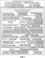
- FIG. 1 is an illustration of a functional block diagram showing exemplary versions of a scalable area gripper 10 that is part of a scalable area gripper system 12 of the disclosure, used in an exemplary version of an automated material handling system 14 of the disclosure.
- the blocks in FIG. 1 represent elements, and lines connecting the various blocks do not imply any particular dependency of the elements.
- the connecting lines shown in the various Figures contained herein are intended to represent example functional relationships and/or physical couplings between the various elements, but it is noted that other alternative or additional functional relationships or physical connections may be present in versions disclosed herein.
- One or more of these blocks may be combined, divided, or combined and divided into different blocks when implemented in an illustrative example.
- the illustrations of the scalable area gripper 10, the scalable area gripper system 12, and the automated material handling system 14 in FIG. 1 are not meant to imply physical or architectural limitations to the manner in which illustrative examples may be implemented.
- Other components in addition to, or in place of, the ones illustrated may be used. Some components may be unnecessary.
- the scalable area gripper 10 that is part of the scalable area gripper system 12.
- the automated material handling system 14 for a material handling process 16 in composite manufacturing 18 of composite structures 20, where the automated material handling system 14 includes the scalable area gripper system 12 with the scalable area gripper 10.
- the automated material handling system 14 comprises a robot 22 (see also FIG. 4 ), such as a pick-and-place (PNP) operations robot 22a.
- the robot 22 has an arm 24 (see FIG. 4 ) with an end effector 26 (see FIG. 4 ).
- the end effector 26 has a first end 28a (see FIG. 4 ) and a second end 28b (see FIG. 4 ).
- the scalable area gripper 10 is coupled to the first end 28a of the end effector 26, and the second end 28b of the end effector 26 is coupled to the arm 24 of the robot 22.
- the scalable area gripper 10 is held by the robot 22, via the end effector 26.
- the automated material handling system 14 further comprises a vacuum (VAC) system 30 having a portion coupled to the end effector 26 or another suitable part of the robot 22, and having a portion coupled to the scalable area gripper 10.
- the vacuum system (VAC. SYS.) 30 comprises a vacuum (VAC.) manifold 32, one or more vacuum (VAC.) lines 34, a vacuum (VAC.) source 35, and a vacuum (VAC.) power supply (SUPP.) 36.
- the vacuum source 35 may comprise a vacuum generator 35a (see FIG. 4 ), a blower, or another suitable vacuum source, configured to pull air 38 (see FIG. 1 ) in an air flow 38a (see FIG.
- the vacuum system 30 may further comprise one or more control valves, shutoff valves, and/or other suitable vacuum system components.
- the vacuum manifold 32 is coupled to the scalable area gripper 10, via one or more vacuum lines 34, and the vacuum manifold 32 is coupled to the vacuum source 35, via one or more vacuum lines 34.
- the automated material handling system 14 further comprises a material 40, such as a composite material (COMP. MAT.) 40a, for example, raw composite material (COMP. MAT.) 40b, in the form of one or more plies 42, or layers, such as one or more cut plies 42a, to be picked up by the robot 22 using the scalable area gripper 10 during the material handling process 16 in the composite manufacturing 18.
- the robot 22 positions the scalable area gripper 10 over the top of the material 40, such as the composite material 40a, for example, the raw composite material 40b, in the form of one or more plies 42, such as one or more cut plies 42a, prior to pick up and removal.
- the material 40 such as the composite material 40a, for example, raw composite material 40b, is supplied in the form of carbon or non-carbon dry fabric (FAB.) rolls 44 (see FIGS. 1 , 3 ), dry fabric (FAB.) sheets 46 (see FIGS. 1 , 2 ), or another suitable form, comprised of fiber material (FM) 48, such as unidirectional (UD) fiber material (FM) 48a, for example, unidirectional (UD) carbon (CARB.) fiber material (FM) 48b.
- the fiber material 48 comprises fibers 50, such as unidirectional (UD) fibers 50a, for example, unidirectional (UD) carbon fibers 50b.
- the fibers 50 may be stitched together with threads 52 (see FIG.
- the fibers 50 may be made from natural and/or man-made materials such as carbon, fiberglass, graphite, and the like.
- the material 40 such as the composite material 40a, for example, the raw composite material 40b, has stiffness in a fiber direction 55 (see FIG. 2 ) but has a low bending stiffness, or no stiffness, in a non-fiber direction 56 (see FIG. 2 ), or in any direction relative to the fibers 50.
- the composite material 40a may further comprise carbon fiber reinforced polymer (CFRP) materials, including plastic or thermoplastic materials.
- CFRP carbon fiber reinforced polymer
- the plies 42 Prior to the plies 42, or layers, of the material 40, such as the composite material 40a, being picked up by the robot 22 using the scalable area gripper 10, the plies 42 are cut from the dry fabric rolls 44 (see FIG. 3 ), dry fabric sheets 46 (see FIG. 2 ), or other suitable form, into net shapes 58 (see FIGS. 1 , 3 ) with a cutter apparatus 60 (see FIG. 4 ), such as an automated cross-cutter apparatus 60a (see FIG. 4 ), to form cut plies 42a (see FIGS. 1 , 3 ) arranged in a ply nest 62 (see FIGS. 1 , 3 ).
- a cutter apparatus 60 see FIG. 4
- an automated cross-cutter apparatus 60a see FIG. 4
- the plies 42 such as the cut plies 42a, in the ply nest 62 are adjacent to non-cut material or non-cut composite material, comprising waste material 64 (see FIGS. 1 , 3 ), also referred to as skeleton material, or scrap material.
- the plies 42, such as the cut plies 42a, in the ply nest 62 are configured to be picked up and placed by the robot 22 using the scalable area gripper 10, and separated from the remaining material, such as the remaining composite material, comprising the waste material 64 (see FIGS. 1 , 3 ) that is not picked up.
- One or more portions 64a (see FIGS. 1 , 3 ) of the waste material 64 may be discarded or recycled for re-use.
- One or more plies 42, such as one or more cut plies 42a, in the ply nest 62 can be selectively picked up from a work surface 65 (see FIG. 4 ) by the robot 22, using the scalable area gripper 10, and removed or moved from the work surface 65, to a tool or mold for laying up, or to a carrier apparatus, a kitting tray, a mobile apparatus, or another suitable apparatus for transport.
- the work surface 65 may comprise a conveyor belt 65a (see FIG. 4 ), a cutting table 65b (see FIG. 5D ), a mobile table, a carrier apparatus, a tool, or another suitably flat surface.
- the material 40 such as the composite material 40a, in the form of one or more plies 42, such as one or more cut plies 42a, is selectively picked up from the work surface 65 by the robot 22, using the scalable area gripper 10, and the waste material 64, or skeleton material or scrap material, is not picked up and is left on the work surface 65 for removal and discarding or reuse.
- the scalable area gripper 10 picks up and holds each ply 42, such as each cut ply 42a, to edges 66 (see FIGS. 1 , 3 ) of the ply 42, such as the cut ply 42a, and does not go past the edges 66, thus avoiding picking up the waste material 64, or skeleton material or scrap material.
- the material 40 has one or more boundaries 68 (see FIGS. 1 , 5A ), and the material 40, such as the ply 42, has one or more ply boundaries 70 (see FIGS. 1 , 5A ).
- the material 40, such as the ply 42 further has a plurality of sections 72 (see FIGS. 1 , 5A ), where each section 72 has control points 74 (see FIGS. 1 , 5A ), such as two control points 74, including a start portion 76 (see FIGS. 1 , 5A ), such as a start point 77 (see FIGS. 1 , 5A ), and an end portion (POR.) 78 (see FIGS. 1 , 5A ), such as an end point 79 (see FIGS.
- each section 72 there is a single start portion 76, or start point 77, and a single end portion 78, or end point 79. Further, each section 72 is identified to obtain an identified section (SECT.) 72a (see FIG. 1 ), has a span 82 (see FIG. 1 ) between the start portion 76, such as the start point 77, and the end portion 78, such as the end point 79.
- the one or more boundaries 68, such as the one or more ply boundaries 70, are determined, and adhesion area control 80 (see FIG.
- Adhesion area control 80 based on boundaries 68, such as ply boundaries 70, simplifies control.
- the plurality of sections 72 of the material 40, such as the ply 42 are identified to obtain one or more identified sections 72a (see FIGS. 1 , 5A ), and for each identified section 72a, the start portion 76, such as the start point 77, and the end portion 78, such as the end point 79, are calculated and identified. Further, each section 72, such as each identified section 72a, of the material 40, such as the ply 42, has a span 82 (see FIGS. 1 , 5A ) between the start portion 76, such as the start point 77, and the end portion 78, such as the end point 79. Adhesion area control 80 based on boundaries 68, such as ply boundaries 70, simplifies control and avoids having to use discrete control along the length of each section 72.
- the one or more plies 42 may be placed on a tool or mold for layup and forming, to form a composite layup.
- the one or more plies 42, such as the one or more cut plies 42a may get vacuum bagged, infused with resin, and placed into an autoclave or oven to undergo a curing process, to form a composite laminate.
- the dry fabric rolls 44 or dry fabric sheets 46 may be preimpregnated or infused with a resin material, such as a resin binder, for example, a thermoset material or a thermoplastic material, prior to, or during, the curing process.
- the composite laminate is used to form a composite part 294 (see FIG. 10 ), such as an aircraft composite part 296 (see FIG. 10 ), for example, a spar, such as a wing spar or another type of spar, a rib, a stiffening member, a stringer, a beam, or another suitable composite part.
- the composite part 294, such as the aircraft composite part 296, is used in the manufacture of a vehicle 280 (see FIG. 10 ), such as an aircraft 280a (see FIG. 10 ).
- the composite part 294 may also be made in the manufacture of vehicles 280, including rotorcraft, spacecraft, watercraft, automobiles, trucks, and other suitable vehicles, or in the manufacture of suitable structures.
- the automated material handling system 14 comprises the scalable area gripper system 12 having the scalable area gripper 10.
- the scalable area gripper 10 comprises a structural frame 84.
- the structural frame 84 (see FIGS. 1 , 4 , 5A ) of the scalable area gripper 10 is configured for attachment to, and attaches to, for example, the end effector 26 (see FIG. 4 ) attached to the robot 22 (see FIGS. 1 , 4 ).
- the structural frame 84 comprises a flat apparatus 86 (see FIGS. 1 , 5A ), such as a two-dimensional, generally flat or planar apparatus, having at least two sides 88 (see FIG. 5A ).
- the structural frame 84 comprises four sides 88 that are coupled together to form a rectangular shape 90 or configuration.
- the structural frame 84 comprises a roller apparatus 92 (see FIGS. 1 , 4 , 6A ). As shown in FIG. 6A , the roller apparatus 92 has a body 94 with a cylindrical shape 96 or configuration, and with a circumference 98. In yet other versions, the structural frame 84 comprises a curved apparatus 100 (see FIG. 1 ), other than the roller apparatus 92, and comprises a three-dimensional apparatus with two or more curved sides 101 (see FIG. 1 ), where each curved side 101 has one or more curves 102 (see FIG. 1 ). The structural frame 84 may also comprise another suitably shaped apparatus.
- the scalable area gripper 10 further comprises a plurality of variable vacuum zones 104 (see also FIG. 5A ).
- Each variable vacuum zone 104 has a length 106 (see FIGS. 1 , 5A , 6B ).
- the plurality of variable vacuum zones 104 are coupled to the structural frame 84.
- the plurality of variable vacuum zones 104 are disposed across the flat apparatus 86.
- the plurality of variable vacuum zones 104 are disposed circumferentially along the roller apparatus 92.
- the plurality of variable vacuum zones 104 are disposed across the curved apparatus 100.
- each variable vacuum zone 104 comprises a plurality of vacuum ports 108 (see also FIGS. 5A , 6A ) or openings or orifices.
- Each vacuum port 108 is configured to go, or configured to be moved, between a closed state 110 (see FIGS. 1 , 5A ) and an open state 112 (see FIGS. 1 , 5A ).
- each variable vacuum zone 104 further comprises one or more movable barrier elements 114 (see also FIGS. 5B , 6B ).
- each of the one or more movable barrier elements 114 comprises a movable seal 116 (see FIGS. 1 , 5B ).
- the movable seal 116 may comprise a mechanical (MECH.) seal 116a (see FIGS. 1 , 5B ) comprising a flat elastomeric seal, a flat gasket seal, or another suitable flat seal element.
- the movable seal 116 is made of a flexible, durable, and resilient material, such as elastomer or rubber, a polymer material, synthetic rubber copolymer of acrylonitrile (ACN) and butadiene, nitrile butadiene rubber (NBR), silicone, silicone rubbers, neoprene, fluoroelastomers, or another suitable material.
- the movable seal 116 is designed to block off one or more vacuum ports 108 on each variable vacuum zone 104.
- each of the one or more movable barrier elements 114 comprises a mechanical (MECH.) shield 118 (see FIGS. 1 , 7A-7B ) or shielding, to block air flow 38a through one or more of the plurality of vacuum ports 108 (see FIGS. 7A-7B ) of a selected variable vacuum zone 104 (see FIGS. 7A-7B ).
- the mechanical shield 118 comprises a belt shield assembly (ASSY.) 120 (see also FIG. 1 ).
- each of the one or more movable barrier elements 114 comprises a magnetic zipper seal assembly (ASSY.) 122 (see also FIG. 1 ).
- each variable vacuum zone 104 further comprises an actuator assembly 124 configured to move each of the one or more movable barrier elements 114 across one or more of the plurality of vacuum ports 108, to cause the one or more plurality of vacuum ports 108 to go between the closed state 110 and the open state 112.
- the actuator assembly (ASSY.) 124 may comprise a rotary actuator assembly (ASSY.) 125, a linear actuator assembly (ASSY.) 126, or another suitable actuator assembly. As shown in FIG.
- the linear actuator assembly 126 may comprise a motor driven pulley and cable actuator assembly (ASSY.) 128, a magnet drive assembly (ASSY.) 129, a rack and pinion actuator assembly (ASSY.) 130, a belt drive assembly (ASSY.) 132, a screw drive assembly (ASSY.) 134, or another suitable linear actuator assembly.
- ASSY. motor driven pulley and cable actuator assembly
- ASSY. magnet drive assembly
- ASSY. rack and pinion actuator assembly
- ASSY. belt drive assembly
- ASSY. screw drive assembly
- One or more of the plurality of variable vacuum zones 104 is configured to be adjusted, and is adjusted, to each provide an adjusted vacuum zone 105 (see FIGS. 1 , 5A ) that is aligned above and with, and corresponds to, the identified section 72a of the material 40, such as the ply 42, having the start portion 76, or start point 77, and the end portion 78, or end point 79. As shown in FIGS. 1 , 5A ) that is aligned above and with, and corresponds to, the identified section 72a of the material 40, such as the ply 42, having the start portion 76, or start point 77, and the end portion 78, or end point 79. As shown in FIGS.
- each adjusted vacuum zone 105 has control points 74a, including a start portion 76a, or start point 77a, and an end portion 78a, or end point 79a, and each adjusted vacuum zone 105 is configured to be positioned, and is positioned, adjacent to its corresponding identified section 72a of the material 40, such as the ply 42.
- Each adjusted vacuum zone 105 is configured to be activated, and is activated, to pick up the material 40, such as the ply 42, during the material handling process 16 (see FIG. 1 ) for composite manufacturing 18 (see FIG. 1 ).
- Each adjusted vacuum zone 105 has a span 107 (see FIGS. 1 , 5C ) between the start portion 76a and the end portion 78a.
- the start portion 76 and the end portion 78 of the material 40 are calculated, and the one or more movable barrier elements 114 are moved or driven, via the actuator assembly 124, to the respective start portion 76a and end portion 78a of the adjusted vacuum zone 105 adjacent the corresponding identified section 72a between the start portion 76 and the end portion 78 of the material 40, such as the ply 42.
- the scalable area gripper system 12 further comprises a control system 136 coupled to the scalable area gripper 10.
- the control system 136 may comprise a position controller 138 configured to operably control positioning, and operably controls positioning, of the scalable area gripper 10 with respect to the material 40, such as the ply 42.
- the control system 136 may further comprise an actuator assembly (ASSY.) controller 140 configured to operably control, and operably controls, the actuator assembly 124, to move each of the one or more movable barrier elements 114 across one or more of the plurality of vacuum ports 108 to go between the closed state 110 and the open state 112 of the vacuum ports 108.
- ASSY. actuator assembly
- control system 136 may further comprise a computer 142 configured to process, and processes, a software program 144.
- the software program 144 is configured to determine, and determines, the boundaries 68 of the material 40, such as the ply boundaries 70 of the ply 42, and to calculate the start portion 76 and the end portion 78, based on the boundaries 68 of the material 40, such as the ply boundaries 70 of the ply 42.
- the scalable area gripper system 12 controls material adhesion 146 (see FIG. 1 ), such as ply adhesion 148 (see FIG. 1 ), based on the boundaries 68, such as the ply boundaries 70.
- the control points 74 are set at the start portion 76 and the end portion 78 of the material 40, such as the ply 42, in one dimension, instead of using many individually controlled valves to switch a vacuum along the full length of a vacuum zone or area.
- the plurality of sections 72 of the material 40, such as the ply 42 are identified to obtain one or more identified sections 72a (see FIG. 1 ), and for each identified section 72a, the start portion 76, such as the start point 77, and the end portion 78, such as the end point 79, are calculated and identified. Further, each section 72, such as each identified section 72a, has a span 82 (see FIG. 1 ) between the start portion 76, such as the start point 77, and the end portion 78, such as the end point 79.
- Adhesion area control 80 based on boundaries 68, such as ply boundaries 70, simplifies control.
- an automated material handling system 14 for a material handling process 16 in composite manufacturing 18 comprises the material 40 (see FIG. 1 ), such as the ply 42 (see FIG. 1 ), to be picked up and removed from a work surface 65 (see FIG. 4 ).
- the automated material handling system 14 further comprises the robot 22 (see FIG. 1 ) with the end effector 26 (see FIG. 4 ).
- automated material handling system 14 further comprises the scalable area gripper system 12 (see FIG. 1 ), comprising the scalable area gripper 10 (see FIG. 1 ), discussed in detail above.
- the scalable area gripper 10 has the structural frame 84 and the plurality of variable vacuum zones 104 coupled to the structural frame 84.
- the structural frame 84 comprises a flat apparatus 86, and the plurality of variable vacuum zones 104 are disposed across the flat apparatus 86.
- the structural frame 84 comprises the roller apparatus 92, and the plurality of variable vacuum zones 104 are disposed circumferentially along the roller apparatus 92.
- the structural frame 84 comprises the curved apparatus 100 (see FIG. 1 ), other than the roller apparatus 92, and comprises a three-dimensional apparatus with two or more curved sides 101 (see FIG. 1 ), where each curved side 101 has one or more curves 102 (see FIG. 1 ).
- the structural frame 84 may also comprise another suitably shaped apparatus.
- Each variable vacuum zone 104 comprises a plurality of vacuum ports 108 (see FIG. 1 ).
- Each variable vacuum zone 104 further comprises one or more movable barrier elements 114 (see FIG. 1 ).
- Each of the one or more movable barrier elements 114 comprises one of, a movable seal 116 (see FIGS. 1 , 5B ), such as a mechanical seal 116a (see FIGS. 1 , 5B ), a magnetic zipper seal assembly 122 (see FIG. 8A ), a mechanical shield 118 (see FIG. 7A ), including a belt shield assembly 120 (see FIG. 7A ), or another suitable movable barrier element.
- Each variable vacuum zone 104 further comprises the actuator assembly 124 (see FIG. 1 ) configured to move each of the one or more movable barrier elements 114 across one or more of the plurality of vacuum ports 108, to cause the one or more plurality of vacuum ports 108 to go between the closed state 110 (see FIG. 1 ) and the open state 112 (see FIG. 1 ).
- the actuator assembly 124 may comprise the rotary actuator assembly 125, the linear actuator assembly 126, or another suitable actuator assembly.
- the linear actuator assembly 126 may comprise the motor driven pulley and cable actuator assembly 128, the magnet drive assembly 129, the rack and pinion actuator assembly 130, the belt drive assembly 132, the screw drive assembly 134, or another suitable linear actuator assembly.
- the scalable area gripper system 12 of the automated material handling system 14 further comprises the control system 136 (see FIG. 1 ) coupled to the scalable area gripper 10.
- the control system 136 comprises the position controller 138 (see FIG. 1 ) configured to operably control positioning, and operably controls positioning, of the scalable area gripper 10 with respect to the material 40, such as the ply 42.
- the control system 136 further comprises the actuator assembly controller 140 (see FIG. 1 ) configured to operably control, and operably controls, the actuator assembly 124, to move each of the one or more movable barrier elements 114 across one or more of the plurality of vacuum ports 108.
- the control system 136 further comprises a computer 142 (see FIG.
- the software program 144 is configured to determine, and determines, boundaries 68 of the material 40, such as ply boundaries 70 of the ply 42, and to calculate the start portion 76 and the end portion 78, based on the boundaries 68 of the material 40, such as the ply boundaries 70 of the ply 42.
- the automated material handling system 14 further comprises the vacuum system 30 (see FIG. 1 ) coupled to the scalable area gripper 10.
- the vacuum system 30 has the vacuum source 35 to provide air 38 (see FIG. 1 ), such as air flow 38a (see FIG. 1 ), through the one or more plurality of vacuum ports 108 in the open state 112.
- the scalable area gripper system 12 is configured to adjust, and adjusts, one or more of the plurality of variable vacuum zones 104, to each provide an adjusted vacuum zone 105 (see FIG. 1 ) that corresponds to a corresponding identified section 72a (see FIG. 1 ) of the material 40, such as the ply 42, having the start portion 76 (see FIG. 1 ), such as the start point 77 (see FIG. 1 ), and the end portion 78 (see FIG. 1 ), such as the end point 79 (see FIG.
- the scalable area gripper system 12 is configured to position, and positions, each adjusted vacuum zone 105 adjacent to its corresponding identified section 72a of the material 40, such as the ply 42, and is configured to activate, and activates, the adjusted vacuum zone 105, to pick up and remove the material 40, such as the ply, from the work surface 65 during the material handling process 16 in the composite manufacturing 18.
- FIG. 2 is an illustration of a front perspective view of an exemplary version of material 40, such as fiber material 48, having fibers 50, such as unidirectional fibers 50a, stitched together with threads 52, to form a stitched unidirectional fabric 54, that may be used with some versions of the scalable area gripper system 12 (see FIG. 1 ) discussed above, and picked up with a version of the scalable area gripper 10 (see FIG. 1 ) discussed above.
- the material 40, such as the fiber material 48 comprises dry fabric sheets 46 to form plies 42 (see FIG. 1 ).
- the fibers 50 may be made from natural and/or man-made materials such as carbon, fiberglass, graphite, and the like.
- the material 40, such as the fiber material 48 has stiffness in a fiber direction 55 (see FIG. 2 ) but has a low bending stiffness, or no stiffness, in a non-fiber direction 56 (see FIG. 2 ).
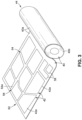
- FIG. 3 is an illustration of a side perspective view of an exemplary version of a dry fabric roll 44 of material 40, such as composite material 40a, for example, raw composite material 40b, showing plies 42, such as cut plies 42a, cut into net shapes 58 of various geometric configurations with edges 66, and arranged in a ply nest 62.
- FIG. 3 further shows waste material 64, such as portions 64a of waste material 64, also referred to as skeleton material or scrap material, adjacent the plies 42, such as the cut plies 42a.
- the plies 42, such as the cut plies 42a are cut and nested from the dry fabric roll 44 and are cut with a cutter apparatus 60 (see FIG.
- the plies 42 such as the cut plies 42a, are configured to be picked up and placed by the robot 22 (see FIG. 4 ) using the scalable area gripper 10, and are configured to be separated from the remaining material, such as the remaining composite material, comprising the waste material 64, or skeleton material, that is not picked up.
- the plies 42, such as the cut plies 42a, that are selectively picked up from, for example, the work surface 65 (see FIG. 4 ) by the robot 22 using the scalable area gripper 10, may be laid directly on a tool or mold for laying up, or on a carrier apparatus, a mobile apparatus, or another suitable apparatus for forming or transport.
- FIG. 4 is an illustration of a front perspective view of a production cell 150 for performing the material handling process 16 (see FIG. 1 ) for composite manufacturing 18 (see FIG. 1 ), where the production cell 150 incorporates exemplary versions of the automated material handling system 14 and the scalable area gripper system 12 of the disclosure, as discussed above.
- the production cell 150 includes a dry fabric roll 44 of material 40, such as composite material 40a, for example, carbon fabric, from which plies 42, such as cut plies 42a, are cut.
- the production cell 150 further includes the cutter apparatus 60, such as the automated cross-cutter apparatus 60a, for cutting plies 42, such as the cut plies 42a, from the dry fabric roll 44, into net shapes 58 of various geometric configurations and arranged in the ply nest 62.
- the production cell 150 further includes the work surface 65 (see FIG. 4 ), such as the conveyor belt 65a, from which the plies 42, such as the cut plies 42a, in the ply nest 62 are moved after being cut with the cutter apparatus 60, such as the automated cross-cutter apparatus 60a.
- the production cell 150 further includes the automated material handling system 14 comprising the robot 22, such as the pick-and-place operations robot 22a, and the vacuum system 30.
- the robot 22, such as the pick-and-place operations robot 22a includes the arm 24 with the end effector 26.
- the scalable area gripper 10 (see FIG. 4 ) of the scalable area gripper system 12 (see FIG. 4 ), is coupled to the first end 28a (see FIG. 4 ) of the end effector 26, and the second end 28b (see FIG. 4 ) of the end effector 26 is coupled to the arm 24 of the robot 22.
- the scalable area gripper 10 is held by the robot 22, via the end effector 26. As shown in FIG.
- the end effector 26 is mounted to a gantry 152.
- the gantry 152 is configured to move, and moves, the end effector 26 of the robot 22 over the one or more plies 42, such as one or more cut plies 42a, to be picked up, and lowers the end effector 26 with the attached scalable area gripper 10, so that one or more surfaces 154 (see FIG. 4 ) of the scalable area gripper 10 are in contact with a surface 43 (see FIG. 4 ) of each of the one or more plies 42, such as the one or more cut plies 42a, to be picked up from the work surface 65, and removed from the waste material 64 (see FIG. 4 ), or skeleton material.
- the vacuum system 30 has the vacuum manifold 32 coupled to the scalable area gripper 10, and the vacuum manifold 32 is coupled to the vacuum source 35, via a vacuum line 34.
- the vacuum manifold 32 distributes air 38 (see FIG. 1 ) from the vacuum line 34 to the entire end effector 26.
- the vacuum manifold 32 is part of the end effector 26.
- the vacuum manifold 32 is coupled to the arm 24, prior to the end effector 26.
- the vacuum power supply 36 (see FIG. 4 ) is coupled to the vacuum source 35.
- the vacuum source 35 comprises a vacuum generator 35a (see FIG. 4 ). However, the vacuum source 35 may comprise a blower or another suitable vacuum source.
- the vacuum system 30 is configured to pull air 38 (see FIG. 1 ) in an air flow 38a (see FIG. 1 ), or vacuum flow, through the scalable area gripper 10 to pick up, and adhere or secure, the desired plies 42, such as cut plies 42a, to one or more surfaces 154 (see FIG. 4 ) of the scalable area gripper 10.
- the automated material handling system 14 and the scalable area gripper system 12 of the production cell 150 may be operated by an operator using the control system 136 (see FIG. 4 ) for operatively controlling operations of the automated material handling system 14 and the scalable area gripper system 12, and other components of the production cell 150, including coordinating and controlling movements of the dry fabric roll 44, the cutter apparatus 60, such as the automated cross-cutter apparatus 60a, the work surface 65, such as the conveyor belt 65a, the vacuum system 30, the gantry 152, and the end effector 26 with the attached scalable area gripper 10.
- the control system 136 comprises a computer 142.
- the computer 142 may comprise a portable computer (PC), a programmable logic controller (PLC), or another suitable computer.
- the computer 142 uses a software program 144 (see FIG. 1 ), which may include an algorithm or logic, that determines how the material handling process 16 should progress and the sequential operation of the components of the production cell 150.
- FIGS. 5A-5E show exemplary versions of a scalable area gripper 10, such as in the form of a scalable area gripper 10a, having a structural frame 84 in the form of a flat apparatus 86 with a rectangular shape 90 and with sides 88, such as sides 88a, 88b, 88c, and 88d.
- FIG. 5A is an illustration of a bottom view of an exemplary version of the scalable area gripper 10, such as in the form of scalable area gripper 10a, having the structural frame 84 in the form of the flat apparatus 86, and gripping a material 40, such as a ply 42, for example, a cut ply 42a.
- the scalable area gripper 10 is part of the scalable area gripper system 12 (see FIG. 5A ), which also includes the control system 136 (see FIG. 5A ).
- a ply 42 such as a cut ply 42a, for example, a first ply 42b
- the scalable area gripper 10a is gripped and picked up with the scalable area gripper 10, such as the scalable area gripper 10a.
- other plies 42 such as cut plies 42a
- FIG. 5A further shows portions 64a of waste material 64 adjacent the plies 42, such as the cut plies 42a.
- FIG. 5A further shows portions 64a of waste material 64 adjacent the plies 42, such as the cut plies 42a.
- the first ply 42b has a plurality of sections 72.
- One or more of the plurality of sections 72 are identified to obtain one or more identified sections 72a (see FIG. 5A ), each having a span 82 (see FIG. 5A ) between the start portion 76, such as the start point 77, and the end portion 78, such as the end point 79.
- the scalable area gripper 10 comprises a plurality of variable vacuum zones 104 coupled to sides 88, such as sides 88a, 88b, across the structural frame 84.
- Each variable vacuum zone 104 has a length 106 (see FIG. 5A ).
- Each variable vacuum zone 104 comprises a plurality of vacuum ports 108 (see FIG. 5A ), such as circular vacuum ports 108a.
- the vacuum ports 108 may also be another suitable shape.
- Each variable vacuum zone 104 is coupled to movable barrier elements 114 (see FIG. 5A ), such as a movable seals 116 (see FIG. 5A ), for example, two (2) movable seals 116.
- Each variable vacuum zone further comprises an actuator assembly 124 (see FIG. 5A ), such as a linear actuator assembly 126 (see FIG. 5A ), coupled to the movable barrier elements 114, such as the movable seals 116.
- the actuator assembly 124 such as the linear actuator assembly 126, is configured to move each movable barrier element 114 across one or more of the plurality of vacuum ports 108, to cause the one or more plurality of vacuum ports 108 to go between the closed state 110 (see FIG. 5A ) and the open state 112 (see FIG. 5A ). As shown in FIG. 5A ), such as a linear actuator assembly 126 (see FIG. 5A ), coupled to the movable barrier elements 114, such as the movable seals 116.
- the actuator assembly 124 such as the linear actuator assembly 126, is configured to move each movable barrier element 114 across one or more of the plurality of vacuum ports 108, to cause the one or more plurality of vacuum ports 108 to go between the closed state 110 (see
- each actuator assembly 124 such as the linear actuator assembly 126
- connection elements 156 such as wired connection elements or wireless connection elements
- the actuator assembly controller 140 is configured to operably control, and operably controls, the actuator assembly 124, such as the linear actuator assembly 126, to move the movable barrier elements 114, such as the movable seals 116, across one or more of the plurality of vacuum ports 108.
- variable vacuum zones 104 each have an adjusted vacuum zone 105 having a start portion 76a, such as a start point 77a, and having an end portion 78a, such as an end point 79a.
- Each adjusted vacuum zone 105 has vacuum ports 108 in the open state 112 (see FIG. 5A ).
- each variable vacuum zone 104 is adjusted to have an adjusted vacuum zone 105 that corresponds to a corresponding identified section 72a of the first ply 42b having the start portion 76 and the end portion 78.
- Each adjusted vacuum zone 105 is configured to be positioned adjacent to its corresponding identified section 72a of the first ply 42b, and is configured to be activated to pick up the first ply 42b.
- variable vacuum zones 104 each have one or more inactive vacuum zones 158, including a first inactive vacuum zone 158a and a second inactive vacuum zone 158b, both blocked by the movable barrier elements 114, such as the movable seals 116, which block the vacuum ports 108 of the inactive vacuum zones 158.
- the vacuum ports 108 of the inactive vacuum zones 158, including the first inactive vacuum zone 158a and the second inactive vacuum zone 158b, of each variable vacuum zone 104, are in the closed state 110 (see FIG. 5A ).
- the scalable area gripper 10 such as in the form of scalable area gripper 10a, is coupled to a vacuum system 30 (see FIGS. 1 , 4 , 5B ), and in particular, the variable vacuum zones 104 are coupled to a vacuum chamber 37 (see FIG. 5B ), which is coupled to a vacuum source 35 (see FIG. 5B ), via vacuum lines 34 (see FIG. 5B ).
- FIG. 5B is an illustration of an enlarged cross-section view of a portion of the scalable area gripper 10, such as in the form of scalable area gripper 10a, taken along lines 5B-5B, of FIG. 5A .
- FIG. 5B shows material 40, such as a ply 42, for example, a cut ply 42a, in the form of first ply 42b, gripped by the scalable area gripper 10, such as in the form of scalable area gripper 10a.
- material 40 such as a ply 42, for example, a cut ply 42a, in the form of first ply 42b, gripped by the scalable area gripper 10, such as in the form of scalable area gripper 10a.
- 5B shows the structural frame 84, such as the flat apparatus 86, the variable vacuum zone 104 with the plurality of vacuum ports 108, such as circular vacuum ports 108a, the movable barrier elements 114, such as the movable seals 116, the actuator assembly 124, such as the linear actuator assembly 126, coupled to the movable barrier elements 114, such as the movable seals 116, and the vacuum system 30 coupled to the scalable area gripper 10, such as in the form of scalable area gripper 10a.
- the structural frame 84 such as the flat apparatus 86
- the variable vacuum zone 104 with the plurality of vacuum ports 108 such as circular vacuum ports 108a
- the movable barrier elements 114 such as the movable seals 116
- the actuator assembly 124 such as the linear actuator assembly 126
- the scalable area gripper 10 such as in the form of scalable area gripper 10a, is coupled to a vacuum system 30, and in particular, the variable vacuum zone 104 is coupled to a vacuum chamber 37, which is coupled to a vacuum source 35, via vacuum lines 34.
- FIG. 5B shows the variable vacuum zone 104 adjusted to have the adjusted vacuum zone 105 that corresponds to a corresponding identified section 72a of the ply 42 having the start portion 76 and the end portion 78.
- the adjusted vacuum zone 105 is positioned adjacent to its corresponding identified section 72a of the first ply 42b, and is configured to be activated to pick up the first ply 42b.
- the adjusted vacuum zone 105 has the start portion 76a and the end portion 78a.
- the adjusted vacuum zone 105 has vacuum ports 108 in the open state 112 (see FIG. 5B ).
- air 38 such as air flow 38a, flows through the vacuum ports 108, in the open state 112, and into the vacuum chamber 37.
- variable vacuum zone 104 has inactive vacuum zones 158, including the first inactive vacuum zone 158a and the second inactive vacuum zone 158b, blocked by the movable barrier elements 114, such as the movable seals 116, which block the vacuum ports 108 of the inactive vacuum zones 158.
- the vacuum ports 108 of the inactive vacuum zones 158, including the first inactive vacuum zone 158a and the second inactive vacuum zone 158b, of the variable vacuum zone 104, are in the closed state 110 (see FIG. 5B ).
- FIG. 5C is an illustration of a top view of an exemplary version of a scalable area gripper system 12 having a scalable area gripper 10, such as in the form of scalable area gripper 10a, of the disclosure, coupled to a control system 136.
- the scalable area gripper 10 such as in the form of scalable area gripper 10a, has a structural frame 84 in the form of a flat apparatus 86 with sides 88 and having a rectangular shape 90.
- FIG. 5C shows plies 42, such as cut plies 42a, and portions 64a of waste material 64, between the plies 42, such as the cut plies 42a, on a work surface 65, such as a cutting table 65b.
- FIG. 5C shows a ply 42, such as a cut ply 42a, comprising a first ply 42b, to be picked up with the scalable area gripper 10, such as the scalable area gripper 10a.
- the first ply 42b has a plurality of sections 72. Each section 72 has a start portion 76, such as a start point 77, and an end portion 78, such as an end point 79.
- FIG. 5C further shows a ply 42, such as a cut ply 42a, comprising a second ply 42c, to be left on the work surface 65, such as the cutting table 65b.
- FIG. 5C further shows a ply 42, such as a cut ply 42a, comprising a third ply 42d, to be left on the work surface 65, such as the cutting table 65b.
- the scalable area gripper 10 comprises the plurality of variable vacuum zones 104 coupled to sides 88, such as sides 88a, 88b, across the structural frame 84.
- Each variable vacuum zone 104 comprises the plurality of vacuum ports 108 and is coupled to movable barrier elements 114, such as movable seals 116, which are actuated, or moved, by an actuator assembly 124, such as a linear actuator assembly 126, configured to move the movable barrier elements 114 across one or more of the plurality of vacuum ports 108, to cause the one or more plurality of vacuum ports 108 to go between the closed state 110 and the open state 112.
- an actuator assembly 124 such as a linear actuator assembly 126
- each variable vacuum zone 104 is adjusted to have an adjusted vacuum zone 105 that corresponds to a corresponding identified section 72a of the first ply 42b having the start portion 76 and the end portion 78.
- Each adjusted vacuum zone 105 is configured to be positioned adjacent to its corresponding identified section 72a of the first ply 42b, and is configured to be activated to pick up the first ply 42b.
- variable vacuum zones 104 each have an adjusted vacuum zone 105 having a start portion 76a, such as a start point 77a, and having an end portion 78a, such as an end point 79a.
- Each adjusted vacuum zone 105 has a span 107 between the start portion 76a and the end portion 78a.
- Each adjusted vacuum zone 105 has vacuum ports 108 in the open state 112 (see FIG. 5C ). As further shown in FIG.
- variable vacuum zones 104 each have inactive vacuum zones 158, including the first inactive vacuum zone 158a and the second inactive vacuum zone 158b, both blocked or covered by the movable barrier elements 114, such as the movable seals 116, which block or cover the vacuum ports 108 of the inactive vacuum zones 158.
- the vacuum ports 108 of the inactive vacuum zones 158, including the first inactive vacuum zone 158a and the second inactive vacuum zone 158b, of each variable vacuum zone 104, are in the closed state 110 (see FIG. 5C ).
- the scalable area gripper 10 such as in the form of scalable area gripper 10a, is coupled to a vacuum system 30 (see FIGS. 1 , 4 , 5E ).
- the variable vacuum zones 104 are coupled to one or more vacuum chambers 37 (see FIG. 5E ), which are coupled to a vacuum manifold 32 (see FIG. 5E ), and the vacuum manifold 32 is coupled to vacuum lines 34 (see FIG. 5E ) connected to a vacuum source 35 (see FIG. 5E ).
- FIG. 5D is an illustration of a cross-section view of plies 42, such as cut plies 42a, and waste material 64, taken along lines 5D-5D of FIG. 5C .
- FIG. 5D shows portions 64a of waste material 64 adjacent a ply 42, such as a cut ply 42a, comprising the first ply 42b, and adjacent a ply 42, such as a cut ply 42a, comprising the third ply 42d.
- the first ply 42b is to be picked up with the scalable area gripper 10 (see FIG. 5C ), such as the scalable area gripper 10a (see FIG. 5C ).
- the third ply 42d is to be left on the work surface 65 (see FIG. 5D ), such as the cutting table 65b (see FIG. 5D ).
- FIG. 5E is an illustration of a top view of an exemplary version of a scalable area gripper 10, such as in the form of scalable area gripper 10a, having the structural frame 84 in the form of the flat apparatus 86 and attached to the vacuum system 30.
- FIG. 5E shows the structural frame 84, such as the flat apparatus 86, having two (2) sides 88a, 88b.
- Vacuum chambers 37 (see FIG. 5E ) and variable vacuum zones 104 (see FIG. 5E ) are coupled between the sides 88a, 88b, of the structural frame 84.
- the vacuum system 30 comprises the vacuum chambers 37 coupled to the vacuum manifold 32, and the vacuum manifold 32 is coupled to vacuum lines 34 connected to the vacuum source 35.
- Each variable vacuum zone 104 has the plurality of vacuum ports 108 (see FIG. 5E ), such as in the form of circular vacuum ports 108a, that are configured to be moved between the closed state 110 and the open state 112.
- the vacuum ports 108 may also be another suitable shape.
- variable vacuum zones 104 each have an adjusted vacuum zone 105 having the start portion 76a, such as the start point 77a, and having the end portion 78a, such as the end point 79a.
- the adjusted vacuum zone 105 has vacuum ports 108 in the open state 112.
- the variable vacuum zones 104 each have inactive vacuum zones 158, including the first inactive vacuum zone 158a and the second inactive vacuum zone 158b, both blocked or covered by movable barrier elements 114, such as mechanical seals 116a, which block or cover the vacuum ports 108 of the inactive vacuum zones 158.
- the vacuum ports 108 of the inactive vacuum zones 158, including the first inactive vacuum zone 158a and the second inactive vacuum zone 158b, are in the closed state 110.
- FIG. 5E further shows the scalable area gripper 10, such as in the form of scalable area gripper 10a, gripping a first ply 42b and a second ply 42c.
- FIG. 5E further comprises the actuator assembly 124, such as a linear actuator assembly 126, coupled to the movable barrier elements 114, such as the mechanical seals 116a.
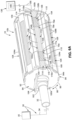
- FIG. 6A is an illustration of a front perspective view of other exemplary versions of a scalable area gripper 10, such as in the form of a scalable area gripper 10b, of the disclosure, having a structural frame 84 in the form of a roller apparatus 92, attached to a vacuum system 30, via a vacuum line 34.
- the roller apparatus 92 has a body 94, such as a cylinder body 94a, having a circumference 98 and a cylindrical shape 96.
- the roller apparatus 92 has a first end 160a (see FIG. 6A ) and a second end 160b (see FIG. 6A ).
- FIG. 6A is an illustration of a front perspective view of other exemplary versions of a scalable area gripper 10, such as in the form of a scalable area gripper 10b, of the disclosure, having a structural frame 84 in the form of a roller apparatus 92, attached to a vacuum system 30, via a vacuum line 34.
- the roller apparatus 92 has a body 94, such as
- the first end 160a has an opening 162 attached to a vacuum manifold 32, and the vacuum manifold 32 is attached to the vacuum line 34 connected to the vacuum system 30 having a vacuum source 35.
- the first end 160a further has an attachment member 164 for attachment to an end effector 26 (see FIG. 4 ) of a robot 22 (see FIG. 4 ).
- the scalable area gripper 10 such as in the form of the scalable area gripper 10b, comprises a portion 104a of the plurality of variable vacuum zones 104 disposed circumferentially along the surface 154 of the roller apparatus 92.
- Each variable vacuum zone 104 has the plurality of vacuum ports 108 (see FIG. 6A ).
- the plurality of vacuum ports 108 comprise slot vacuum ports 108b that are configured to be moved between the closed state 110 and the open state 112.
- FIG. 6A the plurality of vacuum ports 108 comprise slot vacuum ports 108b that are configured to be moved between the closed state 110 and the open state 112.
- one of the variable vacuum zones 104 such as a select variable vacuum zone 104b, has an adjusted vacuum zone 105 having a start portion 76a, such as a start point 77a, and having an end portion 78a, such as an end point 79a.
- the adjusted vacuum zone 105 has vacuum ports 108 in the open state 112. As further shown in FIG.
- the select variable vacuum zone 104a has inactive vacuum zones 158, including the first inactive vacuum zone 158a and the second inactive vacuum zone 158b, both blocked or covered by movable barrier elements 114, such as mechanical shields 118, for example, mechanical shield seals 118a, which block or cover the vacuum ports 108 of the inactive vacuum zones 158 from an interior 166 of the roller apparatus 92.
- the vacuum ports 108 of the inactive vacuum zones 158, including the first inactive vacuum zone 158a and the second inactive vacuum zone 158b, are in the closed state 110.
- the roller apparatus 92 is coupled, via a connection element 156, such as a wired connection element or a wireless connection element, to the actuator assembly controller 140 of the control system 136.
- the actuator assembly controller 140 is configured to operably control the actuator assembly 124 (see FIG. 6B ), such as a motor driven pulley and cable actuator assembly 128 (see FIG. 6B ), to move the movable barrier elements 114, such as the mechanical shields 118, for example, the mechanical shield seals 118a, across one or more of the plurality of vacuum ports 108.
- FIG. 6B is an illustration of a front perspective of an exemplary version of an interior roller apparatus portion 92a of the scalable area gripper 10, such as the scalable area gripper 10b, of FIG. 6A .
- the interior roller apparatus portion 92a has a body 168, such as a cylinder body 168a.
- the interior roller apparatus portion 92a has a first end 170a (see FIG. 6B ) that corresponds to the first end 160a (see FIG. 6A ) of the roller apparatus 92, and the interior roller apparatus portion 92a has a second end 170b (see FIG. 6B ) that corresponds to the second end 160b (see FIG.
- each variable vacuum zone 104 has a length 106 (see FIG. 6B ) and a width 172 (see FIG. 6B ), and a plurality of vacuum ports 108 (see FIG. 6A ) comprising slot vacuum ports 108b configured to be moved between the closed state 110 (see FIG. 6B ) and the open state 112 (see FIG. 6B ).
- one of the variable vacuum zones 104 has an adjusted vacuum zone 105 having a start portion 76a, such as a start point 77a, and having an end portion 78a, such as an end point 79a.
- the adjusted vacuum zone 105 has vacuum ports 108 in the open state 112.
- the variable vacuum zone 104a has inactive vacuum zones 158, including the first inactive vacuum zone 158a and the second inactive vacuum zone 158b, both blocked or covered by the movable barrier elements 114, such as the mechanical shields 118, for example, the mechanical shield seals 118a, which block or cover the vacuum ports 108 of the inactive vacuum zones 158.
- the vacuum ports 108 of the inactive vacuum zones 158 including the first inactive vacuum zone 158a and the second inactive vacuum zone 158b, are in the closed state 110.
- the actuator assembly 124 in the form of the motor driven pulley and cable actuator assembly 128, is coupled to the second end 170b of the interior roller apparatus portion 92a of the roller apparatus 92 (see FIG. 6A ).
- the actuator assembly 124 in the form of the motor driven pulley and cable actuator assembly 128, is configured to drive, or move, the movable barrier elements 114, such as the mechanical shields 118, for example, the mechanical shield seals 118a, across one or more of the plurality of vacuum ports 108, of the variable vacuum zone 104.
- the movable barrier elements 114 such as the mechanical shields 118, for example, the mechanical shield seals 118a
- the motor driven pulley and cable actuator assembly 128 comprises a plurality of cables 174 coupled to a plurality of pulleys 175, and a motor 176 configured to drive, or move, the plurality of cables 174 and the plurality of pulleys 175, which, in turn, drive, or move, the movable barrier elements 114, such as the mechanical shields 118, for example, the mechanical shield seals 118a, across one or more of the plurality of vacuum ports 108, of the variable vacuum zone 104.
- the movable barrier elements 114 such as the mechanical shields 118, for example, the mechanical shield seals 118a
- 6B further shows the movable barrier element 114, such as the mechanical shield 118, for example, the mechanical shield seal 118a, in the form of a roll dispenser 178, for dispensing the movable barrier element 114, such as the mechanical shield 118, for example, the mechanical shield seal 118a, when actuated by the actuator assembly 124, in the form of the motor driven pulley and cable actuator assembly 128.
- the movable barrier element 114 such as the mechanical shield 118, for example, the mechanical shield seal 118a
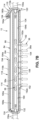
- FIG. 7A is an illustration of a sectional side view of an exemplary version of a scalable area gripper 10 of the disclosure, having a belt shield assembly 120.
- FIG. 7A shows, in some versions, the scalable area gripper 10 having the structural frame 84, such as in the form of the flat apparatus 86, and having the variable vacuum zone 104 with the plurality of vacuum ports 108.
- the scalable area gripper 10 has the structural frame 84, such as in the form of the roller apparatus 92.
- the belt shield assembly 120 comprises a movable barrier element 114, such as in the form of a mechanical shield 118, for example, a mechanical shield seal 118a.
- the belt shield assembly 120 comprise an actuator assembly 124, such as a belt drive assembly 132.
- the belt drive assembly 132 comprises a belt 180 (see FIG. 7A ) that is moved, or driven, with a plurality of belt rollers 182 (see FIG. 7A ) that guide the movable barrier element 114, such as in the form of the mechanical shield 118, for example, a mechanical shield seal 118a, around a portion 184a of a perimeter 184 of the belt 180.
- FIG. 7A the belt shield assembly 120 comprises a movable barrier element 114, such as in the form of a mechanical shield 118, for example, a mechanical shield seal 118a.
- the plurality of belt rollers 182 comprise four (4) belt rollers 182.
- the number of belt rollers 182 may comprise one (1), two (2), three (3), or more than four (4) belt rollers 182.
- the belt rollers 182 are configured to move the belt 180 and guide the movable barrier element 114, such as in the form of a mechanical shield 118, for example, the mechanical shield seal 118a, around the portion 184a of the perimeter 184 of the belt 180.
- the mechanical shield 118 such as the mechanical shield seal 118a, is coupled to the belt 180.
- the belt drive assembly 132 with the belt rollers 182 and the belt 180 is configured to move, and moves, the mechanical shield 118, such as the mechanical shield seal 118a, to block or cover, or unblock and uncover, one or more vacuum ports 108, to cause the vacuum ports 108 to go between the open state 112 and the closed state 110.
- the plurality of belt rollers 182 are coupled, via connection elements 156a, such as wired connection elements or wireless connection elements, to the actuator assembly controller 140 of the control system 136.
- the actuator assembly controller 140 is configured to operably control the actuator assembly 124, such as the belt drive assembly 132, to move the movable barrier elements 114, such as the mechanical shield 118, for example, the mechanical shield seal 118a across one or more of the plurality of vacuum ports 108.
- the scalable area gripper 10 has a vacuum chamber 37 coupled to a vacuum source 35 that supplies air 38, such as air flow 38a, through vacuum ports 108 in the open state 112.
- FIG. 7A shows the adjusted vacuum zone 105, such as an adjusted active vacuum zone 105a, of the variable vacuum zone 104, with the vacuum ports 108 in the open state 112 to allow the air 38, such as the air flow 38a, to flow through the vacuum ports 108 in the adjusted active vacuum zone 105a and into the vacuum chamber 37.
- FIG. 7A shows the adjusted vacuum zone 105, such as an adjusted active vacuum zone 105a, of the variable vacuum zone 104, with the vacuum ports 108 in the open state 112 to allow the air 38, such as the air flow 38a, to flow through the vacuum ports 108 in the adjusted active vacuum zone 105a and into the vacuum chamber 37.
- the mechanical shield 118 such as the mechanical shield seal 118a
- the mechanical shield 118 has a first end 186, such as a starting point 186a, and a second end 188, such as an ending point 188a.
- the first end 186 such as the starting point 186a, starts the inactive vacuum zone 158, and the mechanical shield 118, such as the mechanical shield seal 118a, blocks or covers the vacuum ports 108 in the inactive vacuum zone 158.
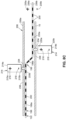
- FIG. 7B is an illustration of a sectional side view of an exemplary version of a scalable area gripper 10 of the disclosure, having a belt shield assembly 120 with movable barrier elements 114 in the form of mechanical shields 118, such as retractable mechanical shield seals 118b.
- the mechanical shields 118 such as the retractable mechanical shield seals 118b, are driven or moved with the actuator assembly 124, such as the belt drive assembly 132.
- FIG. 7B shows, in some versions, the scalable area gripper 10 having the structural frame 84, such as in the form of the flat apparatus 86, and having the variable vacuum zone 104 with the plurality of vacuum ports 108.
- the scalable area gripper 10 has the structural frame 84, such as in the form of the roller apparatus 92.
- the belt shield assembly 120 comprises the movable barrier elements 114, such as in the form of the mechanical shields 118, for example, the retractable mechanical shield seals 118b.
- the belt shield assembly 120 comprise the actuator assembly 124, such as the belt drive assembly 132.
- the belt drive assembly 132 comprises the belt 180 (see FIG. 7B ) that is moved, or driven, with the plurality of belt rollers 182 (see FIG. 7B ) to guide the movable barrier elements 114, such as in the form of the mechanical shields 118, for example, the retractable mechanical shield seals 118b, around portions 184a, 184b, of the perimeter 184 of the belt 180.
- the plurality of belt rollers 182 comprise four (4) belt rollers 182.
- the number of belt rollers 182 may comprise one (1), two (2), three (3), or more than four (4) belt rollers 182.
- a first portion 190a of the mechanical shields 118 is coupled to the belt 180
- a second portion 190b of the mechanical shields 118 is coupled to the belt 180.
- the belt drive assembly 132 with the belt rollers 182 and the belt 180 is configured to move, and moves, the first portion 190a and the second portion 190b of the mechanical shields 118, such as the retractable mechanical shield seals 118b, across, and away from or over, one or more vacuum ports 108, to cause the vacuum ports 108 to go between the open state 112 and the closed state 110.
- the plurality of belt rollers 182 are coupled, via connection elements 156a, such as wired connection elements or wireless connection elements, to the actuator assembly controller 140 (see FIG. 7A ) of the control system 136 (see FIG. 7A ).
- the actuator assembly controller 140 is configured to operably control the actuator assembly 124, such as the belt drive assembly 132, to move the movable barrier elements 114, such as the mechanical shield 118, for example, the retractable mechanical shield seal 118b across one or more of the plurality of vacuum ports 108.
- the scalable area gripper 10 has a vacuum chamber 37 coupled to a vacuum source 35 (see FIG. 7A ) that supplies air 38, such as air flow 38a, through vacuum ports 108 in the open state 112.
- FIG. 7B shows the adjusted vacuum zone 105, such as the adjusted active vacuum zone 105a, of the variable vacuum zone 104, with the vacuum ports 108 in the open state 112 to allow the air 38, such as the air flow 38a, to flow through the vacuum ports 108 in the adjusted active vacuum zone 105a, and into the vacuum chamber 37.
- FIG. 7B shows the adjusted vacuum zone 105, such as the adjusted active vacuum zone 105a, of the variable vacuum zone 104, with the vacuum ports 108 in the open state 112 to allow the air 38, such as the air flow 38a, to flow through the vacuum ports 108 in the adjusted active vacuum zone 105a, and into the vacuum chamber 37.
- FIG. 7B further shows the inactive vacuum zones 158, including the first inactive vacuum zone 158a and the second inactive vacuum zone 158b, of the variable vacuum zone 104, with the vacuum ports 108 in the closed state 110 and blocked or covered, respectively, by the first portion 190a and the second portion 190b of the mechanical shields 118, such as the retractable mechanical shield seals 118b, to block the air 38, such as the air flow 38a, from flowing through the vacuum ports 108 in the inactive vacuum zones 158.
- the mechanical shields 118 such as the retractable mechanical shield seals 118b
- both the first portion 190a and the second portion 190b of the mechanical shields 118 have a first end 192, such as a starting point 192a, and a second end 194, such as an ending point 194a.
- the first end 192 such as the starting point 192a
- the first portion 190a of the mechanical shield 118 such as the retractable mechanical shield seal 118b
- the first end 192 such as the starting point 192a, starts the second inactive vacuum zone 158b
- the second portion 190b of the mechanical shield 118 such as the retractable mechanical shield seal 118b, blocks or covers the vacuum ports 108 in the second inactive vacuum zone 158b.
- the second portion 190b is retracted, or wound up, at the second end 194.
- FIG. 8A is an illustration of a perspective side view of a movable barrier element 114 in the form of a magnetic zipper seal assembly 122 used with some exemplary versions of a scalable area gripper 10.
- the magnetic zipper seal assembly 122 has an open/close mechanism 196 in the form of a single-sided external magnet open/close mechanism 196a.
- the magnetic zipper seal assembly 122 comprises a magnetic seal 198, such as in the form of a magnetic zipper seal 198a, having a plurality of seal magnets 200, incorporated into the magnetic seal 198, such as the magnetic zipper seal 198a.
- the magnetic seal 198 is in the form of a flexible strip 202 with the seal magnets 200 embedded in the flexible strip 202.
- the magnetic seal 198 may be in another suitable form or structure.
- the magnetic zipper seal assembly 122 further comprises a flexible film portion 204 coupled to the magnetic seal 198, such as in the form of the flexible strip 202.
- the flexible strip 202 and the flexible film portion 204 are each comprised of one or more polymer materials, such as thermoplastic, thermoplastic polyurethane, thermoplastic rubber, thermoplastic elastomer, polycarbonate, polyvinylchloride, polyethylene, polyamide, elastomer, rubber, or another suitable polymer material.
- Each seal magnet 200 comprises a magnetic material, such as neodymium (Nd), neodymium iron boron (NdFeB), samarium cobalt (SmCo), alnico, ferrite, or another suitable magnetic material.
- the movable barrier element 114 in the form of the magnetic zipper seal assembly 122 is actuated with an actuator assembly 124 comprising a magnetic drive assembly 129.
- the magnetic drive assembly 129 comprises a movable carriage device 206 configured to travel along, and travels along, one or more elongated members 208, such as one or more rails 208a, in a first direction 210, or forward direction 210a, and configured to travel along the one or more elongated members 208, such as the one or more rails 208a, in a second direction 212, or a back direction 212a.
- Each elongated member 208, such as the rail 208a is made of a ferrous material, such as iron, steel, an alloy of iron or steel, or another suitable ferrous material.
- the magnetic drive assembly 129 further comprises one or more control magnets 214 coupled to the movable carriage device 206.
- the movable carriage device 206 is configured to carry and move, and carries and moves, the control magnets 214 along the one or elongated members 208, such as the one or more rails 208a.
- FIG. 8A shows two control magnets 214.
- the two control magnets 214 comprise a first control magnet 214a (see FIG. 8A ) and a second control magnet 214b (see FIG. 8A ).
- the first control magnet 214a has a first end 215a with a positive pole 216 and a second end 215b with a negative pole 218.
- the second control magnet 214b has a first end 220a with a negative pole 218 and a second end 220b with a positive pole 216.
- the control magnets 214 are positioned on a same side 222 and in sequence, and are positioned external to the magnetic zipper seal assembly 122.
- Each control magnet 214 is secured, or held, in position with a holding magnet 224 (see FIG. 8A ).
- a first holding magnet 224a is positioned on top of the first control magnet 214a, and holds the first control magnet 214a in position or place in the movable carriage device 206.
- a second holding magnet 224b is positioned on top of the second control magnet 214b, and holds the second control magnet 214b in position or place in the movable carriage device 206.
- the control magnets 214 such as the first control magnet 214a and the second control magnet 214b, can be held with another suitable holding apparatus or holding mechanism.
- Each control magnet 214 and each holding magnet 224 comprises a magnetic material, such as neodymium (Nd), neodymium iron boron (NdFeB), samarium cobalt (SmCo), alnico, ferrite, or another suitable magnetic material.
- a magnetic material such as neodymium (Nd), neodymium iron boron (NdFeB), samarium cobalt (SmCo), alnico, ferrite, or another suitable magnetic material.
- FIG. 8A further shows the scalable area gripper 10 with the structural frame 84, such as in the form of the flat apparatus 86, and with the variable vacuum zone 104 having the plurality of vacuum ports 108.
- the scalable area gripper 10 is coupled to the one or more elongated members 208, such as the one or more rails 208a, with one or more attachment elements 225, such as in the form of a threaded bolt screw 225a and nuts 225b.
- the one or more attachment elements 225 may also comprise bolts, rivets, screws, or other suitable attachment elements.
- FIG. 8A further shows the scalable area gripper 10 with the structural frame 84, such as in the form of the flat apparatus 86, and with the variable vacuum zone 104 having the plurality of vacuum ports 108.
- the scalable area gripper 10 is coupled to the one or more elongated members 208, such as the one or more rails 208a, with one or more attachment elements 225, such as in the form of a threaded bolt screw
- FIG. 8A shows a distance 226 between a top surface 228 of the scalable area gripper 10 and a bottom surface 230 of the elongated member 208, such as the rail 208a.
- An opening distance of the magnetic zipper seal assembly 122 is the distance 226 minus a thickness of the magnetic zipper seal assembly 122 (the flexible film portion 204 coupled to the magnetic seal 198).
- the opening distance is preferably in a range of 2 mm (two millimeters) to 8 mm (eight millimeters).
- the switching mechanism internal to the rails 208a where, as shown in FIG.
- control magnets 214 are positioned internal to the magnetic zipper seal assembly 122, or where, as shown in FIG. 8F , non-ferrous elements 242 are positioned internal to the magnetic zipper seal assembly 122, the opening distance is preferably in a range of 4 mm (four millimeters) to 15 mm (fifteen millimeters).
- the control magnets 214 are both positioned on the same side 222 and along an upper side 236a of the magnetic zipper seal assembly 122, and the scalable area gripper is positioned along a lower side 236b of the magnetic zipper seal assembly 122.
- the magnetic zipper seal assembly 122 is positioned under, or below, the one or more elongated members 208, such as the one or more rails 208a, supporting the magnetic drive assembly 129, and is positioned on top of, or above, the vacuum ports 108 of the variable vacuum zone 104 of the scalable area gripper 10.
- magnetic repulsion forces 232 (see FIGS. 8A-8B ) from the second control magnet 214b to the seal magnets 200 in the magnetic seal 198 cause the magnetic seal 198 and the flexible film portion 204 to move downwardly over one or more vacuum ports 108, to cause the one or more vacuum ports 108 to be in the closed state 110 (see FIG. 1 ) and to cause the magnetic zipper seal assembly 122 to be in a sealed state 233a (see FIGS. 8A-8B ).
- magnetic attraction forces 234 from the first control magnet 214a to the seal magnets 200 in the magnetic seal 198 cause the magnetic seal 198 and the flexible film portion 204 to move upwardly over one or more vacuum ports 108, to cause the one or more vacuum ports 108 to be in the open state 112 (see FIG. 8A ) and to cause the magnetic zipper seal assembly 122 to be in an unsealed state 233b (see FIGS. 8A-8B ).
- the opening and closing of the magnetic zipper seal assembly 122 uses the magnetic attraction forces 234 and the magnetic repulsion forces 232 from the separate control magnets 214 located on the same side 222 (see FIGS. 8A-8B ) and located external to the magnetic zipper seal assembly 122.
- the magnetic zipper seal assembly 122 has a positive polarity 235a on the upper side 236a of the magnetic zipper seal assembly 122 and a negative polarity 235b on the lower side 236b of the magnetic zipper seal assembly 122.
- FIG. 8B is a schematic illustration of a side view of the magnetic zipper seal assembly 122 of FIG. 8A , having the open/close mechanism 196 in the form of the single-sided external magnet open/close mechanism 196a.
- FIG. 8B shows the magnetic zipper seal assembly 122 comprising the magnetic seal 198, such as in the form of the magnetic zipper seal 198a, with the seal magnets 200.
- the magnetic zipper seal assembly 122 has the positive polarity 235a on the upper side 236a and the negative polarity 235b on the lower side 236b.
- the 8B further shows the control magnets 214, such as the first control magnet 214a and the second control magnet 214b, and the elongated member 208, such as the rail 208a, made of the ferrous material, such as iron, steel, an alloy of iron or steel, or another suitable ferrous material.
- the first control magnet 214a has the first end 215a with the positive pole 216 and the second end 215b with the negative pole 218.
- the second control magnet 214b has the first end 220a with the negative pole 218 and the second end 220b with the positive pole 216.
- the first control magnet 214a has magnetic attraction forces 234 to the seal magnets 200 in the magnetic zipper seal assembly 122, and causes the magnetic zipper seal assembly 122 to be in the unsealed state 233b.
- the second control magnet 214b has magnetic repulsion forces 232 to the seal magnets 200 in the magnetic zipper seal assembly 122, and causes the magnetic zipper seal assembly 122 to be in the sealed state 233a.
- the magnetic zipper seal assembly 122 is positioned between the control magnets 214, which are both positioned on the same side 222, and the scalable area gripper 10.
- the opening and closing of the magnetic zipper seal assembly 122 uses the magnetic attraction forces 234 (see FIG. 8B ) and the magnetic repulsion forces 232 (see FIG. 8B ) from the separate control magnets 214 located on the same side 222 (see FIG. 8B ) and located external to the magnetic zipper seal assembly 122.
- FIG. 8C is a schematic illustration of a side view of a magnetic zipper seal assembly 122 having the open/close mechanism 196 in the form of a two-sided external magnet attraction open/close mechanism 196b for opening and closing the magnetic zipper seal assembly 122.
- FIG. 8C shows the magnetic zipper seal assembly 122 comprising the magnetic seal 198, such as in the form of the magnetic zipper seal 198a, with the seal magnets 200.
- the magnetic zipper seal assembly 122 has the positive polarity 235a on the upper side 236a and the negative polarity 235b on the lower side 236b.
- FIG. 8C further shows the control magnets 214, such as the first control magnet 214a and the second control magnet 214b on opposite sides 238 of the magnetic zipper seal assembly 122.
- the first control magnet 214a is positioned on the elongated member 208, such as the rail 208a, made of the ferrous material, and is positioned above, and external to, the magnetic zipper seal assembly 122.
- the second control magnet 214b is positioned below the scalable area gripper 10, and is positioned below, and external to, the magnetic zipper seal assembly 122. As shown in FIG.
- the first control magnet 214a has the first end 215a with the positive pole 216 and the second end 215b with the negative pole 218, and the first control magnet 214a has magnetic attraction forces 234 to the seal magnets 200 in the magnetic zipper seal assembly 122, and causes the magnetic zipper seal assembly 122 to be in the unsealed state 233b.
- the second control magnet 214b has the first end 220a with the positive pole 216 and the second end 220b with the negative pole 218, and the second control magnet 214b has magnetic attraction forces 234 to the seal magnets 200 in the magnetic zipper seal assembly 122, and causes the magnetic zipper seal assembly 122 to be in the sealed state 233a.
- the magnetic zipper seal assembly 122 is positioned between the control magnets 214.
- the open/close mechanism 196 in the form of the two-sided external magnet attraction open/close mechanism 196b
- the opening and closing of the magnetic zipper seal assembly 122 uses the magnetic attraction forces 234 (see FIG. 8C ) from the separate control magnets 214 located on opposite sides 238 (see FIG. 8C ) and located external to the magnetic zipper seal assembly 122.
- FIG. 8D is a schematic illustration of a side view of a magnetic zipper seal assembly 122 having the open/close mechanism 196 in the form of a two-sided external magnet repulsion open/close mechanism 196c for opening and closing the magnetic zipper seal assembly 122.
- FIG. 8D shows the magnetic zipper seal assembly 122 comprising the magnetic seal 198, such as in the form of the magnetic zipper seal 198a, with the seal magnets 200.
- the magnetic zipper seal assembly 122 has the positive polarity 235a on the upper side 236a and the negative polarity 235b on the lower side 236b.
- FIG. 8D further shows the control magnets 214, such as the first control magnet 214a and the second control magnet 214b on opposite sides 238 of the magnetic zipper seal assembly 122.
- the first control magnet 214a is positioned below the scalable area gripper 10, and is positioned below, and external to, the magnetic zipper seal assembly 122.
- the second control magnet 214b is positioned on the elongated member 208, such as the rail 208a, made of the ferrous material, and is positioned above, and external to, the magnetic zipper seal assembly 122. As shown in FIG.
- the first control magnet 214a has the first end 215a with the negative pole 218 and the second end 215b with the positive pole 216, and the first control magnet 214a has magnetic repulsion forces 232 to the seal magnets 200 in the magnetic zipper seal assembly 122, and causes the magnetic zipper seal assembly 122 to be in the unsealed state 233b.
- the second control magnet 214b has the first end 220a with the negative pole 218 and the second end 220b with the positive pole 216, and the second control magnet 214b has magnetic repulsion forces 232 to the seal magnets 200 in the magnetic zipper seal assembly 122, and causes the magnetic zipper seal assembly 122 to be in the sealed state 233a.
- the magnetic zipper seal assembly 122 is positioned between the control magnets 214.
- the open/close mechanism 196 in the form of the two-sided external magnet repulsion open/close mechanism 196c, the opening and closing of the magnetic zipper seal assembly 122 uses the magnetic repulsion forces 232 (see FIG. 8D ) from the separate control magnets 214 located on opposite sides 238 (see FIG. 8D ) and located external to the magnetic zipper seal assembly 122.
- FIG. 8E is a schematic illustration of a side view of a magnetic zipper seal assembly 122 having the open/close mechanism 196 in the form of a two-sided internal magnet repulsion open/close mechanism 196d for opening and closing the magnetic zipper seal assembly 122.
- FIG. 8E shows the magnetic zipper seal assembly 122 comprising the magnetic seal 198, such as in the form of the magnetic zipper seal 198a, with the seal magnets 200.
- the magnetic zipper seal assembly 122 has the positive polarity 235a on the upper side 236a and the negative polarity 235b on the lower side 236b.
- FIG. 8E further shows the control magnets 214, such as the first control magnet 214a and the second control magnet 214b on opposite sides 238 of the magnetic zipper seal assembly 122, and positioned internal to the magnetic zipper seal assembly 122.
- the first control magnet 214a is positioned above the scalable area gripper 10, and is positioned below, and internal to, the magnetic zipper seal assembly 122.
- the second control magnet 214b is positioned below the elongated member 208, such as the rail 208a, made of the ferrous material, and is positioned above, and internal to, the magnetic zipper seal assembly 122. As shown in FIG.
- the first control magnet 214a has the first end 215a with the negative pole 218 and the second end 215b with the positive pole 216, and the first control magnet 214a has magnetic repulsion forces 232 to the seal magnets 200 in the magnetic zipper seal assembly 122, and causes the magnetic zipper seal assembly 122 to be in the unsealed state 233b.
- the second control magnet 214b has the first end 220a with the negative pole 218 and the second end 220b with the positive pole 216, and the second control magnet 214b has magnetic repulsion forces 232 to the seal magnets 200 in the magnetic zipper seal assembly 122, and causes the magnetic zipper seal assembly 122 to be in the sealed state 233a.
- the magnetic zipper seal assembly 122 is positioned between the control magnets 214.
- the open/close mechanism 196 in the form of the two-sided internal magnet repulsion open/close mechanism 196d, the opening and closing of the magnetic zipper seal assembly 122 uses the magnetic repulsion forces 232 (see FIG. 8E ) from the separate control magnets 214 located on opposite sides 238 (see FIG. 8E ) and located internal to the magnetic zipper seal assembly 122.
- FIG. 8F is a schematic illustration of a side view of a physical mechanism 240, such as a physical switch seal 240a, to open and close the movable barrier element 114, such as the magnetic zipper seal assembly 122.
- FIG. 8F shows the magnetic zipper seal assembly 122 comprising the magnetic seal 198, such as in the form of the magnetic zipper seal 198a, with the seal magnets 200.
- FIG. 8F further shows non-ferrous elements 242, including a first non-ferrous element 242a and a second non-ferrous element 242b, positioned on opposite sides 238 of the magnetic zipper seal assembly 122, and positioned internal to the magnetic zipper seal assembly 122.
- the non-ferrous elements 242 are each made of a non-ferrous material that is not magnetic.
- the non-ferrous material may comprise a metal or alloy that does not have iron (non-iron metal or non-iron alloy), does not have steel (non-steel metal or non-steel alloy), or does not have iron or steel components.
- the non-ferrous material may comprise a metal such as copper, aluminum, nickel, zinc, lead, tin, manganese, brass, bronze, or another suitable non-ferrous metal material.
- the non-ferrous material may also comprise plastics, composites, or other suitable non-ferrous materials.
- the first non-ferrous element 242a is positioned above the scalable area gripper 10, and is positioned below, and internal to, the magnetic zipper seal assembly 122.
- the second non-ferrous element 242b is positioned below the elongated member 208, such as the rail 208a, made of the ferrous material, and is positioned above, and internal to, the magnetic zipper seal assembly 122.
- the first non-ferrous element 242a and the second non-ferrous element 242b physically interact with the magnetic zipper seal assembly 122, such as pushing and moving the magnetic zipper seal assembly 122 from one side to the next side.
- Magnetic forces for example, magnetic attraction forces 234 (see FIG.
- the magnetic zipper seal assembly 122 is positioned between the non-ferrous elements 242.
- the open/close mechanism 196 in the form of the physical mechanism 240, such as a physical switch seal 240a
- the opening and closing of the magnetic zipper seal assembly 122 uses the non-ferrous elements 242 located on opposite sides 238 (see FIG. 8F ) and located internal to the magnetic zipper seal assembly 122, and adjacent, or near, the ferrous material of the elongated member 208, such as the rail 208a.
- FIG. 9 is an illustration of a flow diagram of an exemplary version of a method 250 of the disclosure.
- the method 250 for picking up a material 40 such as a ply 42 (see FIGS. 1 , 5A ), in a material handling process 16 (see FIG. 1 ) for composite manufacturing 18 (see FIG. 1 ).
- FIG. 9 represent operations and/or portions thereof, or elements, and lines connecting the various blocks do not imply any particular order or dependency of the operations or portions thereof, or elements.
- FIG. 9 and the disclosure of the steps of the method 250 set forth herein should not be interpreted as necessarily determining a sequence in which the steps are to be performed. Rather, although one illustrative order is indicated, it is to be understood that the sequence of the steps may be modified when appropriate. Accordingly, certain operations may be performed in a different order or simultaneously.
- the method 250 comprises step 252 of providing a scalable area gripper system 12 (see FIG. 1 ).
- the scalable area gripper system 12 comprises a scalable area gripper 10 (see FIGS. 1 , 5A , 6A ) having a structural frame 84 (see FIGS. 1 , 5A , 6A ) and a plurality of variable vacuum zones 104 (see FIGS. 1 , 5A , 6A ) coupled to the structural frame 84.
- Each variable vacuum zone 104 comprises, (i) a plurality of vacuum ports 108 (see FIGS. 1 , 5A , 6A ), (ii) one or more movable barrier elements 114 (see FIGS.
- the scalable area gripper system 12 further comprises a control system 136 ( FIGS. 1 , 4 ) coupled to the scalable area gripper 10.
- the step 252 of providing the scalable area gripper system 12 may further comprise, in some versions, providing the scalable area gripper system 12 comprising the scalable area gripper 10 having the structural frame 84 comprising a flat apparatus 86 (see FIGS. 1 , 5A ), where the plurality of variable vacuum zones 104 are disposed across the flat apparatus 86.
- the flat apparatus 86 comprises a two-dimensional, generally flat or planar apparatus, having four sides 88, such as sides 88a, 88b, 88c, 88d, that are coupled together to form a rectangular shape 90 or configuration.
- the step 252 of providing the scalable area gripper system 12 may further comprise, in other versions, providing the scalable area gripper system 12 comprising the scalable area gripper 10 having the structural frame 84 comprising a roller apparatus 92 (see FIGS. 1 , 6A ), where the plurality of variable vacuum zones 104 are disposed circumferentially along the roller apparatus 92.
- the roller apparatus 92 has a body 94 with a cylindrical shape 96 or configuration, and with a circumference 98.
- the structural frame 84 comprises a curved apparatus 100 (see FIG. 1 ), other than the roller apparatus 92, and comprises a three-dimensional apparatus with two or more curved sides 101 (see FIG. 1 ) having one or more curves 102 (see FIG. 1 ), and with the plurality of variable vacuum zones 104 disposed across the curved apparatus 100.
- the structural frame 84 may also comprise another suitably shaped apparatus.
- the step 252 of providing the scalable area gripper system 12 may further comprise, providing the scalable area gripper system 12 comprising the scalable area gripper 10 having the one or more movable barrier elements 114 each comprising one of, a movable seal 116 (see FIGS. 1 , 5A ), a magnetic zipper seal assembly 122 (see FIGS. 1 , 8A ), and a mechanical shield 118 (see FIGS. 1 , 7A ), including a belt shield assembly 120 (see FIGS. 1 , 7A ).
- the method 250 may further comprise opening and closing the magnetic zipper seal assembly 122 using one of, magnetic attraction forces 234 (see FIG. 8A ) and magnetic repulsion forces 232 (see FIG. 8A ) from separate control magnets 214 (see FIG.
- FIG. 8A located between each side of a magnetic seal 198 (see FIG. 8A ) of the magnetic zipper seal assembly 122, or located external to the magnetic seal 198 of the magnetic zipper seal assembly 122, or a physical mechanism 240 (see FIG. 8F ), such as a physical switch seal 240a (see FIG. 8F ), to open and close the magnetic zipper seal assembly 122.
- the movable barrier element 114 comprising the magnetic zipper seal assembly 122, may have an open/close mechanism 196 comprising one of, a single-sided external magnet open/close mechanism 196a (see FIGS. 8A , 8B ), a two-sided external magnet attraction open/close mechanism 196b (see FIG. 8C ), a two-sided external magnet repulsion open/close mechanism 196c (see FIG. 8D ), a two-sided internal magnet repulsion open/close mechanism 196d (see FIG. 8E ), a physical mechanism 240 (see FIG. 8F ), such as a physical switch seal 240a (see FIG. 8F ), or another suitable open/close mechanism.
- an open/close mechanism 196 comprising one of, a single-sided external magnet open/close mechanism 196a (see FIGS. 8A , 8B ), a two-sided external magnet attraction open/close mechanism 196b (see FIG. 8C ), a two-sided external magnet repulsion open/close mechanism 196c (
- the method 250 further comprises step 254 of coupling the scalable area gripper 10 to a vacuum system 30 (see FIGS. 1 , 4 , 5B , 5E , 6A ) and to an end effector 26 (see FIG. 4 ) attached to a robot 22 (see FIGS. 1 , 4 ).
- the method 250 further comprises step 256 of identifying, with the control system 136, a plurality of sections 72 (see FIGS. 1 , 5A ) of the material 40 (see FIGS. 1 , 5A ), such as the ply 42 (see FIGS. 1 , 5A ).
- the method 250 further comprises step 258 of identifying, with the control system 136, a start portion 76 (see FIGS. 1 , 5A ), such as a start point 77 (see FIGS. 1 , 5A ), and an end portion 78 (see FIGS. 1 , 5A ), such as an end point 79 (see FIGS. 1 , 5A ), of each identified section 72a of the material 40, such as the ply 42, based on boundaries 68, such as ply boundaries 70, of the material 40, such as the ply 42.
- the method 250 further comprises step 260 of adjusting one or more of the plurality of variable vacuum zones 104, to each provide an adjusted vacuum zone 105 (see FIGS. 1 , 5A , 6A ) that corresponds to its corresponding identified section 72a of the material 40, such as the ply 42.
- the adjusted vacuum zone 105 may be determined by determining the boundaries 68 of the material 40, such as the ply boundaries 70 of the ply 42, and calculating the start portion 76 and the end portion 78 of each identified section 72a of the material 40, such as the ply 42, and driving or moving the one or more movable barrier elements 114 to a respective start portion 76a (see FIGS. 1 , 5A ) of the adjusted vacuum zone 105, corresponding to the start portion 76, and to a respective end portion 78a (see FIGS. 1 , 5A ) of the adjusted vacuum zone 105, corresponding to the end portion 78.
- the method 250 further comprises step 262 of positioning the adjusted vacuum zone 105 adjacent to its corresponding identified section 72a of the material 40, such as the ply 42. As shown in FIG. 9 , the method 250 further comprises step 264 of activating the adjusted vacuum zone 105 to provide air flow 38a with the vacuum system 30, through the plurality of vacuum ports 108 along the adjusted vacuum zone 105.
- the method 250 further comprises step 266 of picking up the material 40, such as the ply 42, with the scalable area gripper 10, from a work surface 65 (see FIG. 4 ), during the material handling process 16 for the composite manufacturing 18.
- the step 266 of picking up the material 40, such as the ply 42 further comprises, removing and separating the material 40, such as the ply 42, from a waste material 64 (see FIGS. 1 , 4 ), adjacent the material 40, such as the ply 42, on the work surface 65.
- FIG. 10 is an illustration of a perspective view of a vehicle 280, such as an aircraft 280a, incorporating a composite part 294, such as in the form of an aircraft composite part 296, for example, a wing spar, made with an exemplary version of the automated material handling system 14 (see FIG. 1 ) using an exemplary version of the scalable area gripper system 12 having the scalable area gripper 10 disclosed herein.
- the vehicle 280 such as the aircraft 280a, includes a fuselage 282, wings 284, engines 286, and an empennage 288.
- the empennage 288 comprises a vertical stabilizer 290 and horizontal stabilizers 292.
- the composite parts 294 made with the automated material handling system 14 using the scalable area gripper system 12 having the scalable area gripper 10 may be used in a variety of industries and applications including, but not limited to, in connection with the manufacture of aircraft 280a and other aerospace structures and vehicles, including spacecraft, and rotorcraft, as well as vehicles such as watercraft, trains, or other suitable vehicles or structures.
- FIG. 11 is an illustration of a flow diagram of an exemplary aircraft manufacturing and service method 300
- FIG. 12 is an illustration of an exemplary block diagram of an aircraft 316.
- versions of the disclosure may be described in the context of the aircraft manufacturing and service method 300 as shown in FIG. 11
- the aircraft 316 as shown in FIG. 12 .
- exemplary aircraft manufacturing and service method 300 may include specification and design 302 of the aircraft 316 and material procurement 304. During manufacturing, component and subassembly manufacturing 306 and system integration 308 of the aircraft 316 takes place. Thereafter, the aircraft 316 may go through certification and delivery 310 in order to be placed in service 312. While in service 312 by a customer, the aircraft 316 may be scheduled for routine maintenance and service 314 (which may also include modification, reconfiguration, refurbishment, and other suitable services).
- Each of the processes of the aircraft manufacturing and service method 300 may be performed or carried out by a system integrator, a third party, and/or an operator (e.g., a customer).
- a system integrator may include, without limitation, any number of aircraft manufacturers and major-system subcontractors.
- a third party may include, without limitation, any number of vendors, subcontractors, and suppliers.
- An operator may include an airline, leasing company, military entity, service organization, and other suitable operators.
- the aircraft 316 produced by the exemplary aircraft manufacturing and service method 300 may include an airframe 318 with a plurality of systems 320 and an interior 322.
- the plurality of systems 320 may include one or more of a propulsion system 324, an electrical system 326, a hydraulic system 328, and an environmental system 330. Any number of other systems may be included.
- an aerospace example is shown, the principles of the disclosure may be applied to other industries, such as the automotive industry.
- components or subassemblies corresponding to component and subassembly manufacturing 306 may be fabricated or manufactured in a manner similar to components or subassemblies produced while the aircraft 316 is in service 312.
- one or more apparatus examples, method examples, or a combination thereof may be utilized during component and subassembly manufacturing 306 and system integration 308, for example, by substantially expediting assembly of or reducing the cost of the aircraft 316.
- one or more of apparatus examples, method examples, or a combination thereof may be utilized while the aircraft 316 is in service 312, for example and without limitation, to maintenance and service 314.
- Disclosed versions of the scalable area gripper 10 (see FIGS. 1 , 5A , 6A ), the scalable area gripper system 12 (see FIGS. 1 , 4 , 5A ), the automated material handling system 14 (see FIGS. 1 , 4 ), and the method 250 (see FIG. 9 ) provide for a variable zoned gripper and method of gripping a material 40, such as a ply 42, for example, a ply 42 having unidirectional fibers 50a (see FIG. 1 ).
- Adhesion area control 80 (see FIG.
- control points 74 are at a start portion 76 (see FIG. 1 ) and an end portion 78 (see FIG. 1 ) of each ply 42. Setting two control points 74 at the start portion 76 and the end portion 78 of each ply 42 in one dimension, avoids having many individually controlled valves to switch a vacuum along an entire length of the ply 42 or fabric. Further, controlling the ply adhesion 148 (see FIG. 1 ) and the air flow 38a (see FIG. 1 ) at these control points 74, based on the boundaries 68, such as the ply boundaries 70, avoids using discrete control along the length of a section 72 of the ply 42.
- scalable area gripper 10 (see FIGS. 1 , 5A , 6A ), the scalable area gripper system 12 (see FIGS. 1 , 4 , 5A ), the automated material handling system 14 (see FIGS. 1 , 4 ), and the method 250 (see FIG. 9 ) provide for a plurality of variable vacuum zones 104 that enable a scalable area gripper 10 having a structural frame 84 (see FIG. 1 ) in a flat apparatus 86 (see FIGS. 1 , 5A ) form, in a roller apparatus 92 form (see FIGS. 1 , 6A ), or in a curved apparatus 100 (see FIG. 1 ) form.
- variable ply adhesion zone can be implemented with several versions, such as movable barrier elements 114 (see FIG. 1 ), including movable seals 116 (see FIG. 1 ), mechanical shields 118 (see FIG. 1 ), including a belt shield assembly 120 (see FIGS. 1 , 7A ), a magnetic zipper seal assembly 122 (see FIGS. 1 , 8A ), or other suitable movable barrier elements.
- the movable barrier elements 114 are actuated or moved with an actuator assembly 124 (see FIGS. 1 , 5A , 6A ) coupled to the movable barrier elements 114.
- the actuator assembly 124 is configured to move each of the one or more movable barrier elements 114 across one or more vacuum ports 108 of each variable vacuum zone 104, to cause the vacuum ports 108 to go between the closed state 110 (see FIG. 1 ) and the open state 112 (see FIG. 1 ).
- One or more of the plurality of variable vacuum zones 104 is/are configured to be adjusted, to each provide an adjusted vacuum zone 105 (see FIGS. 1 , 5A , 6A ) that corresponds to a corresponding identified section 72a (see FIG. 1 ) of a material 40, such as a ply 42, having the start portion 76 (see FIG. 1 ) and the end portion 78 (see FIG. 1 ).
- each adjusted vacuum zone 105 is configured to be positioned adjacent to its corresponding identified section 72a of the material 40, such as the ply 42, and is configured to be activated to selectively pick up the material 40, such as the ply 42, during a material handling process 16 (see FIG. 1 ) for composite manufacturing 18 (see FIG. 1 ).
- disclosed versions of the scalable area gripper 10 provide a lightweight and rapid solution for actively controlled area grippers for a material handling process 16 for composite manufacturing 18.
- disclosed versions of the scalable area gripper 10 see FIGS. 1 , 5A , 6A ), the scalable area gripper system 12 (see FIGS. 1 , 4 , 5A ), the automated material handling system 14 (see FIGS. 1 , 4 ), and the method 250 (see FIG. 9 ) provide a lightweight and rapid solution for actively controlled area grippers for a material handling process 16 for composite manufacturing 18.
- disclosed versions of the scalable area gripper 10 see FIGS. 1 , 5A , 6A
- the scalable area gripper system 12 see FIGS. 1 , 4 , 5A
- the automated material handling system 14 see FIGS. 1 , 4
- the method 250 see FIG.
- a software program 144 such as a custom software program, may be used to determine the boundaries 68 of the material 40, such as the ply boundaries 70 of the ply 42, to be picked up by the scalable area gripper 10, and may be used to calculate the start portion 76 and the end portion 78 of the ply 42 and the start portion 76a (see FIG. 1 ) and the end portion 78a (see FIG. 1 ) of the adjusted vacuum zone 105 (see FIG. 1 ).
- the actuator assembly 124 is used to drive the one or more movable barrier elements 114 to the start portion 76 and the end portion 78 of the ply 42 and the start portion 76a and the end portion 78a of the adjusted vacuum zone 105.
- scalable area gripper 10 see FIGS. 1 , 5A , 6A
- the scalable area gripper system 12 see FIGS. 1 , 4 , 5A
- the automated material handling system 14 see FIGS. 1 , 4
- the method 250 see FIG.
- a scalable area gripper (10) comprises: a structural frame (84); and a plurality of variable vacuum zones (104) coupled to the structural frame (84), each variable vacuum zone (104) comprises: (i) a plurality of vacuum ports (108); (ii) one or more movable barrier elements (114); and (iii) an actuator assembly (124) configured to move each of the one or more movable barrier elements (114) across one or more of the plurality of vacuum ports (108), to cause the one or more plurality of vacuum ports (108) to go between a closed state (110) and an open state (112), wherein one or more of the plurality of variable vacuum zones (104) is configured to be adjusted, to each provide an adjusted vacuum zone (105) that corresponds to a corresponding identified section (72a) of a material (40) having a start portion (76) and an end portion (78), and further wherein each adjusted vacuum zone (105) is configured to be
- the scalable area gripper (10) is coupled to a control system (136) comprising: a position controller (138) configured to operably control positioning of the scalable area gripper (10) with respect to the material (40); an actuator assembly controller (140) configured to operably control the actuator assembly (124), to move each of the one or more movable barrier elements (114) across one or more of the plurality of vacuum ports (108); and a computer (142) configured to process a software program (144), the software program (144) configured to determine boundaries (68) of the material (40), and to calculate the start portion (76) and the end portion (78), based on the boundaries (68) of the material (40).
- a control system comprising: a position controller (138) configured to operably control positioning of the scalable area gripper (10) with respect to the material (40); an actuator assembly controller (140) configured to operably control the actuator assembly (124), to move each of the one or more movable barrier elements (114) across one or more of the plurality of vacuum ports (108); and
- the structural frame (84) of the scalable area gripper (10) is configured for attachment to an end effector (26) attached to a robot (22).
- the structural frame (84) comprises a flat apparatus (86), and the plurality of variable vacuum zones (104) are disposed across the flat apparatus (86).
- the structural frame (84) comprises a roller apparatus (92), and the plurality of variable vacuum zones (104) are disposed circumferentially along the roller apparatus (92).
- each of the one or more movable barrier elements (114) comprises a movable seal (116).
- each of the one or more movable barrier elements (114) comprises a mechanical shield (118), including a belt shield assembly (120).
- each of the one or more movable barrier elements (114) comprises a magnetic zipper seal assembly (122).
- the actuator assembly (124) comprises one of a rotary actuator assembly (125), and a linear actuator assembly (126), the linear actuator assembly (126) including a motor driven pulley and cable actuator assembly (128), a magnet drive assembly (129), a rack and pinion actuator assembly (130), a belt drive assembly (132), and a screw drive assembly (134).
- an automated material handling system (14) for a material handling process (16) in composite manufacturing (18) comprises: a material (40) to be picked up and removed from a work surface (65); a robot (22) with an end effector (26); a scalable area gripper system (12) comprises: a scalable area gripper (10) having a structural frame (84) and a plurality of variable vacuum zones (104) coupled to the structural frame (84), each variable vacuum zone (104) comprises: (i) a plurality of vacuum ports (108); (ii) one or more movable barrier elements (114); and (iii) an actuator assembly (124) configured to move each of the one or more movable barrier elements (114) across one or more of the plurality of vacuum ports (108), to cause the one or more plurality of vacuum ports (108) to go between a closed state (110) and an open state (112); and a control system (136) coupled to the scalable area gripper (10); and a vacuum system (30) coupled to the scalable
- control system (136) comprises: a position controller (138) configured to operably control positioning of the scalable area gripper (10) with respect to the material (40); an actuator assembly controller (140) configured to operably control the actuator assembly (124), to move each of the one or more movable barrier elements (114) across one or more of the plurality of vacuum ports (108); and a computer (142) configured to process a software program (144), the software program (144) configured to determine boundaries (68) of the material (40), and to calculate the start portion (76) and the end portion (78), based on the boundaries (68) of the material (40).
- the structural frame (84) comprises a flat apparatus (86), and the plurality of variable vacuum zones (104) are disposed across the flat apparatus (86).
- the structural frame (84) comprises a roller apparatus (92), and the plurality of variable vacuum zones (104) are disposed circumferentially along the roller apparatus (92).
- each of the one or more movable barrier elements (114) comprises one of, a movable seal (116), a magnetic zipper seal assembly (122), and a mechanical shield (118), including a belt shield assembly (120).
- providing (252) the scalable area gripper system (12) further comprises, providing the scalable area gripper system (12) comprising the scalable area gripper (10) having the structural frame (84) comprising a flat apparatus (86), where the plurality of variable vacuum zones (104) are disposed across the flat apparatus (86).
- providing (252) the scalable area gripper system (12) further comprises, providing the scalable area gripper system (12) comprising the scalable area gripper (10) having the structural frame (84) comprising a roller apparatus (92), where the plurality of variable vacuum zones (104) are disposed circumferentially along the roller apparatus (92).
- providing (252) the scalable area gripper system (12) further comprises, providing the scalable area gripper system (12) comprising the scalable area gripper (10) having the one or more movable barrier elements (114) each comprising one of, a movable seal (116), a magnetic zipper seal assembly (122), and a mechanical shield (118), including a belt shield assembly (120).
- the method (250) of any of the preceding four paragraphs further comprises opening and closing the magnetic zipper seal assembly (122) using one of, magnetic attraction forces (234) and magnetic repulsion forces (232) from separate control magnets (214) located between each side of a magnetic seal (198) of the magnetic zipper seal assembly (122), or located external to the magnetic seal (198) of the magnetic zipper seal assembly (122), or a physical mechanism (240) to open and close the magnetic zipper seal assembly (122).
- picking up (266) the ply (42) further comprises, removing and separating the ply (42) from a waste material (64) adjacent the ply (42) on the work surface (65).
Landscapes
- Engineering & Computer Science (AREA)
- Mechanical Engineering (AREA)
- Robotics (AREA)
- Chemical & Material Sciences (AREA)
- Composite Materials (AREA)
- Human Computer Interaction (AREA)
- Manufacturing & Machinery (AREA)
- Physics & Mathematics (AREA)
- General Physics & Mathematics (AREA)
- Automation & Control Theory (AREA)
- Moulding By Coating Moulds (AREA)
Abstract
Description
- The disclosure relates generally to the manufacture of composite structures, such as those used in the aircraft industry, and relates more particularly, to an apparatus, system, and method for handling material, such as plies, during a material handling process for composite manufacturing.
- In general, a composite structure is a structure that is formed from two or more constituent component materials with different physical and/or chemical properties that, when combined, produce a composite material having characteristics that are different than the characteristics of the individual components materials.
- As an example, one type of composite material is carbon fiber reinforced plastic ("CFRP"). CFRP generally includes one or more composite layers or plies laminated together to form a sheet, laminate or layup. Each of the composite layers or plies can include a reinforcement material and a matrix material. The matrix material surrounds, binds and supports the reinforcement material. The reinforcement material provides structural strength to the matrix material and the CFRP. The matrix material is generally a non-conductive polymer such as an epoxy resin. The reinforcement material generally consists of strands of carbon fiber, which are electrically conductive.
- Composite structures may be used in a wide variety of applications, including in the manufacture of aircraft, due to their high strength-to-weight ratios, corrosion resistance and other favorable properties. In particular, in aircraft manufacturing, composite structures may be used to form the fuselage, wings, tail sections, and other parts of the aircraft.
- Such composite structures may be formed from composite laminates comprising multiple stacked composite plies, or layers, laminated together. Prior to forming the composite laminates, the composite plies may be cut from rolls or sheets of dry, raw fiber material, for example, unidirectional fiber material, creating a ply nest, and then picked up and typically separated from adjacent waste material. Handling of cut composite plies made of unidirectional fiber material may be difficult due to lack of stiffness in a non-fiber direction. Further, when picking up such cut composite plies from within the ply nest, for example, with a robot, it is desirable for ply adhesion not to extend past the ply edges, so as to leave waste material behind and to prevent disturbance of other cut composite plies in the ply nest. Additionally, such cut composite plies may present in any rotation or geometry. Thus, control of ply adhesion, including a very fine control over where adhesion is applied to a surface of a cut composite ply is desirable.
- Pneumatic valves are typically used in industrial applications where the on/off flow of air, such as compressed air, is controlled. However, because such pneumatic valves are optimized for compressed air, they may not be suitable for pulling vacuum. Moreover, such pneumatic valves are typically individually controlled. Where multiple valves, such as multiple pneumatic valves, are used, valve blocks may be needed to consolidate electronic controls and the plumbing of the air supply. However, such valve blocks, as well as such pneumatic valves, may be bulky in size and heavy in weight, and it may be difficult to arrange them sufficiently close together to achieve a high density of adhesion zones to pick up less stiff materials.
- In addition, the textile industry has a known method for automated material handling of flexible materials that includes adding temporary stiffening agents into the material during the manufacturing process. However, such known method is undesirable for aerospace applications, and in particular, it is undesirable to add temporary stiffening agents to primary aircraft structures, such as fuselage, wings, and tail sections.
- Further, passive check valves are used in some area vacuum grippers that rely on air flow, where the object is not to restrict the air flow, to close the valve. However, such area vacuum grippers with passive check valves do not have discrete control of adhesion zones to pick up less stiff materials, and the entire pick surface of such area vacuum grippers is either active or inactive. Thus, such area vacuum grippers may not be suitable to selectively pick up multiple cut composite plies from across a ply nest.
- Accordingly, there is a need for a scalable area gripper, system, and method for handling and selectively removing material, such as cut composite plies, in composite manufacturing, that provide simplified adhesion area control based on ply boundaries and a determination of a start portion and an end portion of an identified section of a ply, that avoid a need for discrete control along a length of the identified section, and that provide additional advantages over known apparatuses, systems, and methods.
- Examples of the present disclosure provide a scalable area gripper, system, and method for a material handling process in composite manufacturing. As discussed in the below detailed description, versions of the scalable area gripper, system, and method may provide significant advantages over known apparatuses, methods, and systems.
- In a version of the disclosure, there is provided a scalable area gripper. The scalable area gripper comprises a structural frame and a plurality of variable vacuum zones coupled to the structural frame.
- Each variable vacuum zone comprises, (i) a plurality of vacuum ports, (ii) one or more movable barrier elements, and (iii) an actuator assembly configured to move each of the one or more movable barrier elements across one or more of the plurality of vacuum ports, to cause the one or more plurality of vacuum ports to go between a closed state and an open state.
- One or more of the plurality of variable vacuum zones is configured to be adjusted to each provide an adjusted vacuum zone that corresponds to a corresponding identified section of a material having a start portion and an end portion. Each adjusted vacuum zone is configured to be positioned adjacent to its corresponding identified section of the material, and is configured to be activated to pick up the material during a material handling process.
- In another version of the disclosure, there is provided an automated material handling system for a material handling process in composite manufacturing. The automated material handling system comprises a material to be picked up and removed from a work surface. The automated material handling system further comprises a robot with an end effector.
- The automated material handling system further comprises a scalable area gripper system. The scalable area gripper system comprises a scalable area gripper having a structural frame and a plurality of variable vacuum zones coupled to the structural frame. Each variable vacuum zone comprises, (i) a plurality of vacuum ports, (ii) one or more movable barrier elements, and (iii) an actuator assembly configured to move each of the one or more movable barrier elements across one or more of the plurality of vacuum ports, to cause the one or more plurality of vacuum ports to go between a closed state and an open state.
- The scalable area gripper system further comprises a control system a control system coupled to the scalable area gripper. The automated material handling system further comprises a vacuum system coupled to the scalable area gripper. The vacuum system has a vacuum supply to provide air flow through the one or more plurality of vacuum ports in the open state.
- The scalable area gripper system is configured to adjust one or more of the plurality of variable vacuum zones, to each provide an adjusted vacuum zone that corresponds to a corresponding identified section of the material having a start portion and an end portion. The scalable area gripper system is configured to position each adjusted vacuum zone adjacent to its corresponding identified section of the material, and is configured to activate the adjusted vacuum zone, to pick up and remove the material from the work surface during the material handling process in the composite manufacturing.
- In another version of the disclosure, there is provided a method of picking up a ply in a material handling process for composite manufacturing. The method comprises the step of providing a scalable area gripper system. The scalable area gripper system comprises a scalable area gripper having a structural frame and a plurality of variable vacuum zones coupled to the structural frame. Each variable vacuum zone comprises, (i) a plurality of vacuum ports, (ii) one or more movable barrier elements, and (iii) an actuator assembly configured to move each of the one or more movable barrier elements across one or more of the plurality of vacuum ports, to cause the one or more plurality of vacuum ports to go between a closed state and an open state. The scalable area gripper system further comprises a control system coupled to the scalable area gripper.
- The method further comprises the step of coupling the scalable area gripper to a vacuum system and to an end effector attached to a robot. The method further comprises the step of identifying, with the control system, a plurality of sections of the ply. The method further comprises the step of identifying, with the control system, a start portion and an end portion of each identified section of the ply, based on boundaries of the ply.
- The method further comprises the step of adjusting one or more of the plurality of variable vacuum zones, to each provide an adjusted vacuum zone that corresponds to its corresponding identified section of the ply. The method further comprises the step of positioning the adjusted vacuum zone adjacent to its corresponding identified section of the ply.
- The method further comprises the step of activating the adjusted vacuum zone to provide air flow, with the vacuum system, through the plurality of vacuum ports along the adjusted vacuum zone. The method further comprises the step of picking up the ply, with the scalable area gripper, from a work surface, during the material handling process for the composite manufacturing.
- The features, functions, and advantages that have been discussed can be achieved independently in various versions of the disclosure or may be combined in yet other versions, further details of which can be seen with reference to the following description and drawings.
- The disclosure can be better understood with reference to the following detailed description taken in conjunction with the accompanying drawings, which illustrate preferred and exemplary versions, but which are not necessarily drawn to scale. The drawings are examples and not meant as limitations on the description or claims.
-
FIG. 1 is an illustration of a functional block diagram showing exemplary versions of a scalable area gripper and a scalable area gripper system of the disclosure, used in an exemplary version of an automated material handling system of the disclosure; -
FIG. 2 is an illustration of a front perspective view of an exemplary version of fiber material having unidirectional fibers that may be used with versions of the automated material handling system and the scalable area gripper system of the disclosure; -
FIG. 3 is an illustration of a side perspective view of an exemplary version of a dry fabric roll of material showing cut plies arranged in a ply nest; -
FIG. 4 is an illustration of a front perspective view of a production cell incorporating exemplary versions of an automated material handling system and a scalable area gripper system of the disclosure; -
FIG. 5A is an illustration of a bottom view of an exemplary version of a scalable area gripper of the disclosure, having a structural frame in the form of a flat apparatus; -
FIG. 5B is an illustration of an enlarged cross-section view of a portion of the scalable area gripper, taken alonglines 5B-5B, ofFIG. 5A ; -
FIG. 5C is an illustration of a top view of an exemplary version of a scalable area gripper of the disclosure, having a structural frame in the form of a flat apparatus; -
FIG. 5D is an illustration of a cross-section view of cut plies and waste material, taken alonglines 5D-5D ofFIG. 5C ; -
FIG. 5E is an illustration of a top view of an exemplary version of a scalable area gripper having a structural frame in the form of a flat apparatus attached to a vacuum system; -
FIG. 6A is an illustration of a front perspective view of another exemplary version of a scalable area gripper of the disclosure, having a structural frame in the form of a roller apparatus attached to a vacuum system; -
FIG. 6B is an illustration of a front perspective of an exemplary version of an interior portion of the scalable area gripper ofFIG. 6A ; -
FIG. 7A is an illustration of a sectional side view of an exemplary version of a scalable area gripper of the disclosure, having a belt shield assembly; -
FIG. 7B is an illustration of a sectional side view of an exemplary version of a scalable area gripper of the disclosure, having a belt shield assembly with a retractable mechanical shield seal; -
FIG. 8A is an illustration of a perspective side view of a movable barrier element in the form of a magnetic zipper seal assembly used with an exemplary version of a scalable area gripper; -
FIG. 8B is a schematic illustration of a side view of the magnetic zipper seal assembly ofFIG. 8A , having a single-sided external magnet open/close mechanism; -
FIG. 8C is a schematic illustration of a side view of a magnetic zipper seal assembly having a two-sided external magnet attraction open/close mechanism; -
FIG. 8D is a schematic illustration of a side view of a magnetic zipper seal assembly having a two-sided external magnet repulsion open/close mechanism; -
FIG. 8E is a schematic illustration of a side view of a magnetic zipper seal assembly having a two-sided internal magnet repulsion open/close mechanism; -
FIG. 8F is a schematic illustration of a side view of a physical mechanism to open and close a movable barrier element; -
FIG. 9 is an illustration of a flow diagram of an exemplary version of a method of the disclosure; -
FIG. 10 is an illustration of a perspective view of an aircraft incorporating an aircraft part made with an exemplary version of an automated material handling system using an exemplary version of a scalable area gripper system having a scalable area gripper of the disclosure; -
FIG. 11 is an illustration of a flow diagram of an exemplary aircraft manufacturing and service method; and -
FIG. 12 is an illustration of an exemplary block diagram of an aircraft. - The figures shown in this disclosure represent various examples of the versions presented, and only differences will be discussed in detail.
- Disclosed versions will now be described more fully hereinafter with reference to the accompanying drawings, in which some, but not all of the disclosed versions are shown. Indeed, several different versions may be provided and should not be construed as limited to the versions set forth herein. Rather, these versions are provided so that this disclosure will be thorough and fully convey the scope of the disclosure to those skilled in the art.
- This specification includes references to "one version" or "a version". The instances of the phrases "one version" or "a version" do not necessarily refer to the same version. Particular features, structures, or characteristics may be combined in any suitable manner consistent with this disclosure.
- As used herein, "comprising" is an open-ended term, and as used in the claims, this term does not foreclose additional structures or steps.
- As used herein, "configured to" means various parts or components may be described or claimed as "configured to" perform a task or tasks. In such contexts, "configured to" is used to connote structure by indicating that the parts or components include structure that performs those task or tasks during operation. As such, the parts or components can be said to be configured to perform the task even when the specified part or component is not currently operational (e.g., is not on).
- As used herein, the terms "first", "second", etc., are used as labels for nouns that they precede, and do not imply any type of ordering (e.g., spatial, temporal, logical, etc.).
- As used herein, an element or step recited in the singular and preceded by the word "a" or "an" should be understood as not necessarily excluding the plural of the elements or steps.
- As used herein, the phrase "at least one of," when used with a list of items, means different combinations of one or more of the listed items may be used, and only one of each item in the list may be needed. In other words, "at least one of' means any combination of items and number of items may be used from the list, but not all of the items in the list are required. The item may be a particular object, a thing, or a category.
- Now referring to the Figures,
FIG. 1 is an illustration of a functional block diagram showing exemplary versions of ascalable area gripper 10 that is part of a scalablearea gripper system 12 of the disclosure, used in an exemplary version of an automatedmaterial handling system 14 of the disclosure. The blocks inFIG. 1 represent elements, and lines connecting the various blocks do not imply any particular dependency of the elements. Furthermore, the connecting lines shown in the various Figures contained herein are intended to represent example functional relationships and/or physical couplings between the various elements, but it is noted that other alternative or additional functional relationships or physical connections may be present in versions disclosed herein. One or more of these blocks may be combined, divided, or combined and divided into different blocks when implemented in an illustrative example. Further, the illustrations of thescalable area gripper 10, the scalablearea gripper system 12, and the automatedmaterial handling system 14 inFIG. 1 are not meant to imply physical or architectural limitations to the manner in which illustrative examples may be implemented. Other components in addition to, or in place of, the ones illustrated may be used. Some components may be unnecessary. - In some versions of the disclosure, as shown in
FIG. 1 , there is provided thescalable area gripper 10 that is part of the scalablearea gripper system 12. In other versions of the disclosure, as shown inFIG. 1 , there is provided the automatedmaterial handling system 14 for amaterial handling process 16 incomposite manufacturing 18 of composite structures 20, where the automatedmaterial handling system 14 includes the scalablearea gripper system 12 with thescalable area gripper 10. - As shown in
FIG. 1 , in some versions, the automatedmaterial handling system 14 comprises a robot 22 (see alsoFIG. 4 ), such as a pick-and-place (PNP)operations robot 22a. Therobot 22 has an arm 24 (seeFIG. 4 ) with an end effector 26 (seeFIG. 4 ). Theend effector 26 has afirst end 28a (seeFIG. 4 ) and asecond end 28b (seeFIG. 4 ). Thescalable area gripper 10 is coupled to thefirst end 28a of theend effector 26, and thesecond end 28b of theend effector 26 is coupled to thearm 24 of therobot 22. Thescalable area gripper 10 is held by therobot 22, via theend effector 26. - As shown in
FIG. 1 , the automatedmaterial handling system 14 further comprises a vacuum (VAC)system 30 having a portion coupled to theend effector 26 or another suitable part of therobot 22, and having a portion coupled to thescalable area gripper 10. As shown inFIG. 1 , the vacuum system (VAC. SYS.) 30 comprises a vacuum (VAC.)manifold 32, one or more vacuum (VAC.) lines 34, a vacuum (VAC.)source 35, and a vacuum (VAC.) power supply (SUPP.) 36. Thevacuum source 35 may comprise avacuum generator 35a (seeFIG. 4 ), a blower, or another suitable vacuum source, configured to pull air 38 (seeFIG. 1 ) in anair flow 38a (seeFIG. 1 ), or vacuum flow, through the one ormore vacuum lines 34, thevacuum manifold 32, and thescalable area gripper 10. Thevacuum system 30 may further comprise one or more control valves, shutoff valves, and/or other suitable vacuum system components. Thevacuum manifold 32 is coupled to thescalable area gripper 10, via one ormore vacuum lines 34, and thevacuum manifold 32 is coupled to thevacuum source 35, via one or more vacuum lines 34. - As shown in
FIG. 1 , the automatedmaterial handling system 14 further comprises amaterial 40, such as a composite material (COMP. MAT.) 40a, for example, raw composite material (COMP. MAT.) 40b, in the form of one ormore plies 42, or layers, such as one or more cut plies 42a, to be picked up by therobot 22 using thescalable area gripper 10 during thematerial handling process 16 in thecomposite manufacturing 18. Therobot 22 positions thescalable area gripper 10 over the top of thematerial 40, such as thecomposite material 40a, for example, the rawcomposite material 40b, in the form of one ormore plies 42, such as one or more cut plies 42a, prior to pick up and removal. - The
material 40, such as thecomposite material 40a, for example, rawcomposite material 40b, is supplied in the form of carbon or non-carbon dry fabric (FAB.) rolls 44 (seeFIGS. 1 ,3 ), dry fabric (FAB.) sheets 46 (seeFIGS. 1 ,2 ), or another suitable form, comprised of fiber material (FM) 48, such as unidirectional (UD) fiber material (FM) 48a, for example, unidirectional (UD) carbon (CARB.) fiber material (FM) 48b. As shown inFIG. 1 , thefiber material 48 comprisesfibers 50, such as unidirectional (UD)fibers 50a, for example, unidirectional (UD)carbon fibers 50b. Thefibers 50 may be stitched together with threads 52 (seeFIG. 2 ) to form a stitched unidirectional fabric 54 (seeFIG. 2 ), may have tackifiers to hold thefibers 50 together, or may be held together in another suitable manner. Thefibers 50 may be made from natural and/or man-made materials such as carbon, fiberglass, graphite, and the like. Thematerial 40, such as thecomposite material 40a, for example, the rawcomposite material 40b, has stiffness in a fiber direction 55 (seeFIG. 2 ) but has a low bending stiffness, or no stiffness, in a non-fiber direction 56 (seeFIG. 2 ), or in any direction relative to thefibers 50. Thecomposite material 40a may further comprise carbon fiber reinforced polymer (CFRP) materials, including plastic or thermoplastic materials. - Prior to the
plies 42, or layers, of thematerial 40, such as thecomposite material 40a, being picked up by therobot 22 using thescalable area gripper 10, theplies 42 are cut from the dry fabric rolls 44 (seeFIG. 3 ), dry fabric sheets 46 (seeFIG. 2 ), or other suitable form, into net shapes 58 (seeFIGS. 1 ,3 ) with a cutter apparatus 60 (seeFIG. 4 ), such as an automatedcross-cutter apparatus 60a (seeFIG. 4 ), to form cut plies 42a (seeFIGS. 1 ,3 ) arranged in a ply nest 62 (seeFIGS. 1 ,3 ). Theplies 42, such as the cut plies 42a, in theply nest 62 are adjacent to non-cut material or non-cut composite material, comprising waste material 64 (seeFIGS. 1 ,3 ), also referred to as skeleton material, or scrap material. Theplies 42, such as the cut plies 42a, in theply nest 62 are configured to be picked up and placed by therobot 22 using thescalable area gripper 10, and separated from the remaining material, such as the remaining composite material, comprising the waste material 64 (seeFIGS. 1 ,3 ) that is not picked up. One ormore portions 64a (seeFIGS. 1 ,3 ) of thewaste material 64 may be discarded or recycled for re-use. - One or
more plies 42, such as one or more cut plies 42a, in theply nest 62 can be selectively picked up from a work surface 65 (seeFIG. 4 ) by therobot 22, using thescalable area gripper 10, and removed or moved from thework surface 65, to a tool or mold for laying up, or to a carrier apparatus, a kitting tray, a mobile apparatus, or another suitable apparatus for transport. The work surface 65 (seeFIG. 4 ) may comprise aconveyor belt 65a (seeFIG. 4 ), a cutting table 65b (seeFIG. 5D ), a mobile table, a carrier apparatus, a tool, or another suitably flat surface. Thematerial 40, such as thecomposite material 40a, in the form of one ormore plies 42, such as one or more cut plies 42a, is selectively picked up from thework surface 65 by therobot 22, using thescalable area gripper 10, and thewaste material 64, or skeleton material or scrap material, is not picked up and is left on thework surface 65 for removal and discarding or reuse. Thescalable area gripper 10 picks up and holds eachply 42, such as each cut ply 42a, to edges 66 (seeFIGS. 1 ,3 ) of theply 42, such as thecut ply 42a, and does not go past theedges 66, thus avoiding picking up thewaste material 64, or skeleton material or scrap material. - The
material 40 has one or more boundaries 68 (seeFIGS. 1 ,5A ), and thematerial 40, such as theply 42, has one or more ply boundaries 70 (seeFIGS. 1 ,5A ). Thematerial 40, such as theply 42, further has a plurality of sections 72 (seeFIGS. 1 ,5A ), where eachsection 72 has control points 74 (seeFIGS. 1 ,5A ), such as twocontrol points 74, including a start portion 76 (seeFIGS. 1 ,5A ), such as a start point 77 (seeFIGS. 1 ,5A ), and an end portion (POR.) 78 (seeFIGS. 1 ,5A ), such as an end point 79 (seeFIGS. 1 ,5A ). For eachsection 72 there is asingle start portion 76, or startpoint 77, and asingle end portion 78, orend point 79. Further, eachsection 72 is identified to obtain an identified section (SECT.) 72a (seeFIG. 1 ), has a span 82 (seeFIG. 1 ) between thestart portion 76, such as thestart point 77, and theend portion 78, such as theend point 79. The one ormore boundaries 68, such as the one ormore ply boundaries 70, are determined, and adhesion area control 80 (seeFIG. 1 ) of thematerial 40, such as theply 42, to thescalable area gripper 10, is based on the one ormore boundaries 68, such as the one ormore ply boundaries 70.Adhesion area control 80 based onboundaries 68, such asply boundaries 70, simplifies control. - The plurality of
sections 72 of thematerial 40, such as theply 42, are identified to obtain one or moreidentified sections 72a (seeFIGS. 1 ,5A ), and for each identifiedsection 72a, thestart portion 76, such as thestart point 77, and theend portion 78, such as theend point 79, are calculated and identified. Further, eachsection 72, such as each identifiedsection 72a, of thematerial 40, such as theply 42, has a span 82 (seeFIGS. 1 ,5A ) between thestart portion 76, such as thestart point 77, and theend portion 78, such as theend point 79.Adhesion area control 80 based onboundaries 68, such asply boundaries 70, simplifies control and avoids having to use discrete control along the length of eachsection 72. - After the one or
more plies 42, such as the one or more cut plies 42a, are picked up by therobot 22 using thescalable area gripper 10, the one ormore plies 42, such as the one or more cut plies 42a, may be placed on a tool or mold for layup and forming, to form a composite layup. The one ormore plies 42, such as the one or more cut plies 42a may get vacuum bagged, infused with resin, and placed into an autoclave or oven to undergo a curing process, to form a composite laminate. The dry fabric rolls 44 ordry fabric sheets 46 may be preimpregnated or infused with a resin material, such as a resin binder, for example, a thermoset material or a thermoplastic material, prior to, or during, the curing process. - The composite laminate is used to form a composite part 294 (see
FIG. 10 ), such as an aircraft composite part 296 (seeFIG. 10 ), for example, a spar, such as a wing spar or another type of spar, a rib, a stiffening member, a stringer, a beam, or another suitable composite part. In one illustrative version, thecomposite part 294, such as the aircraftcomposite part 296, is used in the manufacture of a vehicle 280 (seeFIG. 10 ), such as anaircraft 280a (seeFIG. 10 ). Thecomposite part 294 may also be made in the manufacture ofvehicles 280, including rotorcraft, spacecraft, watercraft, automobiles, trucks, and other suitable vehicles, or in the manufacture of suitable structures. - As shown in
FIG. 1 , the automatedmaterial handling system 14 comprises the scalablearea gripper system 12 having thescalable area gripper 10. Thescalable area gripper 10 comprises astructural frame 84. The structural frame 84 (seeFIGS. 1 ,4 ,5A ) of thescalable area gripper 10 is configured for attachment to, and attaches to, for example, the end effector 26 (seeFIG. 4 ) attached to the robot 22 (seeFIGS. 1 ,4 ). In some versions, thestructural frame 84 comprises a flat apparatus 86 (seeFIGS. 1 ,5A ), such as a two-dimensional, generally flat or planar apparatus, having at least two sides 88 (seeFIG. 5A ). As shown inFIG. 5A , thestructural frame 84 comprises foursides 88 that are coupled together to form arectangular shape 90 or configuration. - In other versions, the
structural frame 84 comprises a roller apparatus 92 (seeFIGS. 1 ,4 ,6A ). As shown inFIG. 6A , theroller apparatus 92 has abody 94 with acylindrical shape 96 or configuration, and with acircumference 98. In yet other versions, thestructural frame 84 comprises a curved apparatus 100 (seeFIG. 1 ), other than theroller apparatus 92, and comprises a three-dimensional apparatus with two or more curved sides 101 (seeFIG. 1 ), where each curved side 101 has one or more curves 102 (seeFIG. 1 ). Thestructural frame 84 may also comprise another suitably shaped apparatus. - As shown in
FIG. 1 , thescalable area gripper 10 further comprises a plurality of variable vacuum zones 104 (see alsoFIG. 5A ). Eachvariable vacuum zone 104 has a length 106 (seeFIGS. 1 ,5A ,6B ). The plurality ofvariable vacuum zones 104 are coupled to thestructural frame 84. For thestructural frame 84 in the form of theflat apparatus 86, as shown inFIG. 5A , the plurality ofvariable vacuum zones 104 are disposed across theflat apparatus 86. For thestructural frame 84 in the form of theroller apparatus 92, as shown inFIG. 6A , the plurality ofvariable vacuum zones 104 are disposed circumferentially along theroller apparatus 92. For thestructural frame 84 in the form of the curved apparatus 100, the plurality ofvariable vacuum zones 104 are disposed across the curved apparatus 100. - As further shown in
FIG. 1 , eachvariable vacuum zone 104 comprises a plurality of vacuum ports 108 (see alsoFIGS. 5A ,6A ) or openings or orifices. Eachvacuum port 108 is configured to go, or configured to be moved, between a closed state 110 (seeFIGS. 1 ,5A ) and an open state 112 (seeFIGS. 1 ,5A ). - As shown in
FIG. 1 , eachvariable vacuum zone 104 further comprises one or more movable barrier elements 114 (see alsoFIGS. 5B ,6B ). In some versions, each of the one or moremovable barrier elements 114 comprises a movable seal 116 (seeFIGS. 1 ,5B ). The movable seal 116 (seeFIG. 5B ) may comprise a mechanical (MECH.)seal 116a (seeFIGS. 1 ,5B ) comprising a flat elastomeric seal, a flat gasket seal, or another suitable flat seal element. Themovable seal 116 is made of a flexible, durable, and resilient material, such as elastomer or rubber, a polymer material, synthetic rubber copolymer of acrylonitrile (ACN) and butadiene, nitrile butadiene rubber (NBR), silicone, silicone rubbers, neoprene, fluoroelastomers, or another suitable material. Themovable seal 116 is designed to block off one ormore vacuum ports 108 on eachvariable vacuum zone 104. - In other versions, discussed in further detail below with respect to
FIGS. 7A-7B , each of the one or moremovable barrier elements 114 comprises a mechanical (MECH.) shield 118 (seeFIGS. 1 ,7A-7B ) or shielding, to blockair flow 38a through one or more of the plurality of vacuum ports 108 (seeFIGS. 7A-7B ) of a selected variable vacuum zone 104 (seeFIGS. 7A-7B ). In some exemplary versions, as shown inFIG. 7A , themechanical shield 118 comprises a belt shield assembly (ASSY.) 120 (see alsoFIG. 1 ). In other versions, discussed in further detail below, with respect toFIGS. 8A-8E , each of the one or moremovable barrier elements 114 comprises a magnetic zipper seal assembly (ASSY.) 122 (see alsoFIG. 1 ). - As shown in
FIG. 1 , eachvariable vacuum zone 104 further comprises anactuator assembly 124 configured to move each of the one or moremovable barrier elements 114 across one or more of the plurality ofvacuum ports 108, to cause the one or more plurality ofvacuum ports 108 to go between theclosed state 110 and theopen state 112. As shown inFIG. 1 , the actuator assembly (ASSY.) 124 may comprise a rotary actuator assembly (ASSY.) 125, a linear actuator assembly (ASSY.) 126, or another suitable actuator assembly. As shown inFIG. 1 , thelinear actuator assembly 126 may comprise a motor driven pulley and cable actuator assembly (ASSY.) 128, a magnet drive assembly (ASSY.) 129, a rack and pinion actuator assembly (ASSY.) 130, a belt drive assembly (ASSY.) 132, a screw drive assembly (ASSY.) 134, or another suitable linear actuator assembly. - One or more of the plurality of
variable vacuum zones 104 is configured to be adjusted, and is adjusted, to each provide an adjusted vacuum zone 105 (seeFIGS. 1 ,5A ) that is aligned above and with, and corresponds to, the identifiedsection 72a of thematerial 40, such as theply 42, having thestart portion 76, or startpoint 77, and theend portion 78, orend point 79. As shown inFIGS. 1 ,5A , each adjustedvacuum zone 105 hascontrol points 74a, including astart portion 76a, or startpoint 77a, and anend portion 78a, orend point 79a, and each adjustedvacuum zone 105 is configured to be positioned, and is positioned, adjacent to its corresponding identifiedsection 72a of thematerial 40, such as theply 42. Each adjustedvacuum zone 105 is configured to be activated, and is activated, to pick up thematerial 40, such as theply 42, during the material handling process 16 (seeFIG. 1 ) for composite manufacturing 18 (seeFIG. 1 ). Each adjustedvacuum zone 105 has a span 107 (seeFIGS. 1 ,5C ) between thestart portion 76a and theend portion 78a. - Once the
boundaries 68 of thematerial 40, such as theply boundaries 70 of theply 42, are determined, thestart portion 76 and theend portion 78 of thematerial 40, such as theply 42, are calculated, and the one or moremovable barrier elements 114 are moved or driven, via theactuator assembly 124, to therespective start portion 76a andend portion 78a of the adjustedvacuum zone 105 adjacent the corresponding identifiedsection 72a between thestart portion 76 and theend portion 78 of thematerial 40, such as theply 42. - As shown in
FIG. 1 , the scalablearea gripper system 12 further comprises acontrol system 136 coupled to thescalable area gripper 10. As shown inFIG. 1 , in some exemplary versions, thecontrol system 136 may comprise aposition controller 138 configured to operably control positioning, and operably controls positioning, of thescalable area gripper 10 with respect to thematerial 40, such as theply 42. As shown inFIG. 1 , thecontrol system 136 may further comprise an actuator assembly (ASSY.)controller 140 configured to operably control, and operably controls, theactuator assembly 124, to move each of the one or moremovable barrier elements 114 across one or more of the plurality ofvacuum ports 108 to go between theclosed state 110 and theopen state 112 of thevacuum ports 108. - As shown in
FIG. 1 , thecontrol system 136 may further comprise acomputer 142 configured to process, and processes, asoftware program 144. Thesoftware program 144 is configured to determine, and determines, theboundaries 68 of thematerial 40, such as theply boundaries 70 of theply 42, and to calculate thestart portion 76 and theend portion 78, based on theboundaries 68 of thematerial 40, such as theply boundaries 70 of theply 42. The scalablearea gripper system 12 controls material adhesion 146 (seeFIG. 1 ), such as ply adhesion 148 (seeFIG. 1 ), based on theboundaries 68, such as theply boundaries 70. The control points 74 are set at thestart portion 76 and theend portion 78 of thematerial 40, such as theply 42, in one dimension, instead of using many individually controlled valves to switch a vacuum along the full length of a vacuum zone or area. The plurality ofsections 72 of thematerial 40, such as theply 42, are identified to obtain one or moreidentified sections 72a (seeFIG. 1 ), and for each identifiedsection 72a, thestart portion 76, such as thestart point 77, and theend portion 78, such as theend point 79, are calculated and identified. Further, eachsection 72, such as each identifiedsection 72a, has a span 82 (seeFIG. 1 ) between thestart portion 76, such as thestart point 77, and theend portion 78, such as theend point 79.Adhesion area control 80 based onboundaries 68, such asply boundaries 70, simplifies control. - In other versions, as shown in
FIG. 1 , an automatedmaterial handling system 14 for amaterial handling process 16 incomposite manufacturing 18 is provided. The automatedmaterial handling system 14 comprises the material 40 (seeFIG. 1 ), such as the ply 42 (seeFIG. 1 ), to be picked up and removed from a work surface 65 (seeFIG. 4 ). The automatedmaterial handling system 14 further comprises the robot 22 (seeFIG. 1 ) with the end effector 26 (seeFIG. 4 ). automatedmaterial handling system 14 further comprises the scalable area gripper system 12 (seeFIG. 1 ), comprising the scalable area gripper 10 (seeFIG. 1 ), discussed in detail above. - As discussed above, and shown in
FIG. 1 , thescalable area gripper 10 has thestructural frame 84 and the plurality ofvariable vacuum zones 104 coupled to thestructural frame 84. In some versions, as shown inFIG. 5A , thestructural frame 84 comprises aflat apparatus 86, and the plurality ofvariable vacuum zones 104 are disposed across theflat apparatus 86. In other versions, as shown inFIG. 6A , thestructural frame 84 comprises theroller apparatus 92, and the plurality ofvariable vacuum zones 104 are disposed circumferentially along theroller apparatus 92. In yet other versions, thestructural frame 84 comprises the curved apparatus 100 (seeFIG. 1 ), other than theroller apparatus 92, and comprises a three-dimensional apparatus with two or more curved sides 101 (seeFIG. 1 ), where each curved side 101 has one or more curves 102 (seeFIG. 1 ). Thestructural frame 84 may also comprise another suitably shaped apparatus. - Each
variable vacuum zone 104 comprises a plurality of vacuum ports 108 (seeFIG. 1 ). Eachvariable vacuum zone 104 further comprises one or more movable barrier elements 114 (seeFIG. 1 ). Each of the one or moremovable barrier elements 114 comprises one of, a movable seal 116 (seeFIGS. 1 ,5B ), such as amechanical seal 116a (seeFIGS. 1 ,5B ), a magnetic zipper seal assembly 122 (seeFIG. 8A ), a mechanical shield 118 (seeFIG. 7A ), including a belt shield assembly 120 (seeFIG. 7A ), or another suitable movable barrier element. - Each
variable vacuum zone 104 further comprises the actuator assembly 124 (seeFIG. 1 ) configured to move each of the one or moremovable barrier elements 114 across one or more of the plurality ofvacuum ports 108, to cause the one or more plurality ofvacuum ports 108 to go between the closed state 110 (seeFIG. 1 ) and the open state 112 (seeFIG. 1 ). As shown inFIG. 1 , theactuator assembly 124 may comprise therotary actuator assembly 125, thelinear actuator assembly 126, or another suitable actuator assembly. As shown inFIG. 1 , thelinear actuator assembly 126 may comprise the motor driven pulley andcable actuator assembly 128, themagnet drive assembly 129, the rack andpinion actuator assembly 130, thebelt drive assembly 132, thescrew drive assembly 134, or another suitable linear actuator assembly. - The scalable
area gripper system 12 of the automatedmaterial handling system 14 further comprises the control system 136 (seeFIG. 1 ) coupled to thescalable area gripper 10. As discussed above, in some versions, thecontrol system 136 comprises the position controller 138 (seeFIG. 1 ) configured to operably control positioning, and operably controls positioning, of thescalable area gripper 10 with respect to thematerial 40, such as theply 42. Thecontrol system 136 further comprises the actuator assembly controller 140 (seeFIG. 1 ) configured to operably control, and operably controls, theactuator assembly 124, to move each of the one or moremovable barrier elements 114 across one or more of the plurality ofvacuum ports 108. Thecontrol system 136 further comprises a computer 142 (seeFIG. 1 ) configured to process, and processes, a software program 144 (seeFIG. 1 ). Thesoftware program 144 is configured to determine, and determines,boundaries 68 of thematerial 40, such asply boundaries 70 of theply 42, and to calculate thestart portion 76 and theend portion 78, based on theboundaries 68 of thematerial 40, such as theply boundaries 70 of theply 42. - The automated
material handling system 14 further comprises the vacuum system 30 (seeFIG. 1 ) coupled to thescalable area gripper 10. Thevacuum system 30 has thevacuum source 35 to provide air 38 (seeFIG. 1 ), such asair flow 38a (seeFIG. 1 ), through the one or more plurality ofvacuum ports 108 in theopen state 112. - The scalable
area gripper system 12 is configured to adjust, and adjusts, one or more of the plurality ofvariable vacuum zones 104, to each provide an adjusted vacuum zone 105 (seeFIG. 1 ) that corresponds to a corresponding identifiedsection 72a (seeFIG. 1 ) of thematerial 40, such as theply 42, having the start portion 76 (seeFIG. 1 ), such as the start point 77 (seeFIG. 1 ), and the end portion 78 (seeFIG. 1 ), such as the end point 79 (seeFIG. 1 ).The scalablearea gripper system 12 is configured to position, and positions, each adjustedvacuum zone 105 adjacent to its corresponding identifiedsection 72a of thematerial 40, such as theply 42, and is configured to activate, and activates, the adjustedvacuum zone 105, to pick up and remove thematerial 40, such as the ply, from thework surface 65 during thematerial handling process 16 in thecomposite manufacturing 18. - Now referring to
FIG. 2, FIG. 2 is an illustration of a front perspective view of an exemplary version ofmaterial 40, such asfiber material 48, havingfibers 50, such asunidirectional fibers 50a, stitched together withthreads 52, to form a stitchedunidirectional fabric 54, that may be used with some versions of the scalable area gripper system 12 (seeFIG. 1 ) discussed above, and picked up with a version of the scalable area gripper 10 (seeFIG. 1 ) discussed above. Thematerial 40, such as thefiber material 48 comprisesdry fabric sheets 46 to form plies 42 (seeFIG. 1 ). Thefibers 50 may be made from natural and/or man-made materials such as carbon, fiberglass, graphite, and the like. Thematerial 40, such as thefiber material 48 has stiffness in a fiber direction 55 (seeFIG. 2 ) but has a low bending stiffness, or no stiffness, in a non-fiber direction 56 (seeFIG. 2 ). - Now referring to
FIG. 3, FIG. 3 is an illustration of a side perspective view of an exemplary version of adry fabric roll 44 ofmaterial 40, such ascomposite material 40a, for example, rawcomposite material 40b, showing plies 42, such as cut plies 42a, cut intonet shapes 58 of various geometric configurations withedges 66, and arranged in aply nest 62.FIG. 3 further showswaste material 64, such asportions 64a ofwaste material 64, also referred to as skeleton material or scrap material, adjacent theplies 42, such as the cut plies 42a. Theplies 42, such as the cut plies 42a, are cut and nested from thedry fabric roll 44 and are cut with a cutter apparatus 60 (seeFIG. 4 ), such as an automatedcross-cutter apparatus 60a (seeFIG. 4 ), or another suitable cutter apparatus. Theplies 42, such as the cut plies 42a, are configured to be picked up and placed by the robot 22 (seeFIG. 4 ) using thescalable area gripper 10, and are configured to be separated from the remaining material, such as the remaining composite material, comprising thewaste material 64, or skeleton material, that is not picked up. Theplies 42, such as the cut plies 42a, that are selectively picked up from, for example, the work surface 65 (seeFIG. 4 ) by therobot 22 using thescalable area gripper 10, may be laid directly on a tool or mold for laying up, or on a carrier apparatus, a mobile apparatus, or another suitable apparatus for forming or transport. - Now referring to
FIG. 4, FIG. 4 is an illustration of a front perspective view of aproduction cell 150 for performing the material handling process 16 (seeFIG. 1 ) for composite manufacturing 18 (seeFIG. 1 ), where theproduction cell 150 incorporates exemplary versions of the automatedmaterial handling system 14 and the scalablearea gripper system 12 of the disclosure, as discussed above. - As shown in
FIG. 4 , theproduction cell 150 includes adry fabric roll 44 ofmaterial 40, such ascomposite material 40a, for example, carbon fabric, from which plies 42, such as cut plies 42a, are cut. As shown inFIG. 4 , theproduction cell 150 further includes thecutter apparatus 60, such as the automatedcross-cutter apparatus 60a, for cuttingplies 42, such as the cut plies 42a, from thedry fabric roll 44, intonet shapes 58 of various geometric configurations and arranged in theply nest 62. Theproduction cell 150 further includes the work surface 65 (seeFIG. 4 ), such as theconveyor belt 65a, from which theplies 42, such as the cut plies 42a, in theply nest 62 are moved after being cut with thecutter apparatus 60, such as the automatedcross-cutter apparatus 60a. - As shown in
FIG. 4 , theproduction cell 150 further includes the automatedmaterial handling system 14 comprising therobot 22, such as the pick-and-place operations robot 22a, and thevacuum system 30. As shown inFIG. 4 , therobot 22, such as the pick-and-place operations robot 22a, includes thearm 24 with theend effector 26. The scalable area gripper 10 (seeFIG. 4 ) of the scalable area gripper system 12 (seeFIG. 4 ), is coupled to thefirst end 28a (seeFIG. 4 ) of theend effector 26, and thesecond end 28b (seeFIG. 4 ) of theend effector 26 is coupled to thearm 24 of therobot 22. Thescalable area gripper 10 is held by therobot 22, via theend effector 26. As shown inFIG. 4 , theend effector 26 is mounted to agantry 152. Thegantry 152 is configured to move, and moves, theend effector 26 of therobot 22 over the one ormore plies 42, such as one or more cut plies 42a, to be picked up, and lowers theend effector 26 with the attachedscalable area gripper 10, so that one or more surfaces 154 (seeFIG. 4 ) of thescalable area gripper 10 are in contact with a surface 43 (seeFIG. 4 ) of each of the one ormore plies 42, such as the one or more cut plies 42a, to be picked up from thework surface 65, and removed from the waste material 64 (seeFIG. 4 ), or skeleton material. - As shown in
FIG. 4 , thevacuum system 30 has thevacuum manifold 32 coupled to thescalable area gripper 10, and thevacuum manifold 32 is coupled to thevacuum source 35, via avacuum line 34. Thevacuum manifold 32 distributes air 38 (seeFIG. 1 ) from thevacuum line 34 to theentire end effector 26. In some versions, thevacuum manifold 32 is part of theend effector 26. In other versions, thevacuum manifold 32 is coupled to thearm 24, prior to theend effector 26. The vacuum power supply 36 (seeFIG. 4 ) is coupled to thevacuum source 35. Thevacuum source 35 comprises avacuum generator 35a (seeFIG. 4 ). However, thevacuum source 35 may comprise a blower or another suitable vacuum source. Thevacuum system 30 is configured to pull air 38 (seeFIG. 1 ) in anair flow 38a (seeFIG. 1 ), or vacuum flow, through thescalable area gripper 10 to pick up, and adhere or secure, the desired plies 42, such as cut plies 42a, to one or more surfaces 154 (seeFIG. 4 ) of thescalable area gripper 10. - The automated
material handling system 14 and the scalablearea gripper system 12 of theproduction cell 150 may be operated by an operator using the control system 136 (seeFIG. 4 ) for operatively controlling operations of the automatedmaterial handling system 14 and the scalablearea gripper system 12, and other components of theproduction cell 150, including coordinating and controlling movements of thedry fabric roll 44, thecutter apparatus 60, such as the automatedcross-cutter apparatus 60a, thework surface 65, such as theconveyor belt 65a, thevacuum system 30, thegantry 152, and theend effector 26 with the attachedscalable area gripper 10. As shown inFIG. 4 , thecontrol system 136 comprises acomputer 142. Thecomputer 142 may comprise a portable computer (PC), a programmable logic controller (PLC), or another suitable computer. In some versions, thecomputer 142 uses a software program 144 (seeFIG. 1 ), which may include an algorithm or logic, that determines how thematerial handling process 16 should progress and the sequential operation of the components of theproduction cell 150. - Now referring to
FIGS. 5A-5E, FIGS. 5A-5E show exemplary versions of ascalable area gripper 10, such as in the form of ascalable area gripper 10a, having astructural frame 84 in the form of aflat apparatus 86 with arectangular shape 90 and withsides 88, such assides FIG. 5A is an illustration of a bottom view of an exemplary version of thescalable area gripper 10, such as in the form ofscalable area gripper 10a, having thestructural frame 84 in the form of theflat apparatus 86, and gripping amaterial 40, such as aply 42, for example, acut ply 42a. Thescalable area gripper 10 is part of the scalable area gripper system 12 (seeFIG. 5A ), which also includes the control system 136 (seeFIG. 5A ). As shown inFIG. 5A , aply 42, such as acut ply 42a, for example, afirst ply 42b, is gripped and picked up with thescalable area gripper 10, such as thescalable area gripper 10a. As shown inFIG. 5A ,other plies 42, such as cut plies 42a, are left on awork surface 65, such as a cutting table 65b.FIG. 5A further showsportions 64a ofwaste material 64 adjacent theplies 42, such as the cut plies 42a. As shown inFIG. 5A , thefirst ply 42b has a plurality ofsections 72. One or more of the plurality ofsections 72 are identified to obtain one or moreidentified sections 72a (seeFIG. 5A ), each having a span 82 (seeFIG. 5A ) between thestart portion 76, such as thestart point 77, and theend portion 78, such as theend point 79. - As shown in
FIG. 5A , thescalable area gripper 10, such as in the form ofscalable area gripper 10a, comprises a plurality ofvariable vacuum zones 104 coupled tosides 88, such assides structural frame 84. Eachvariable vacuum zone 104 has a length 106 (seeFIG. 5A ). Eachvariable vacuum zone 104 comprises a plurality of vacuum ports 108 (seeFIG. 5A ), such ascircular vacuum ports 108a. Thevacuum ports 108 may also be another suitable shape. Eachvariable vacuum zone 104 is coupled to movable barrier elements 114 (seeFIG. 5A ), such as a movable seals 116 (seeFIG. 5A ), for example, two (2)movable seals 116. - Each variable vacuum zone further comprises an actuator assembly 124 (see
FIG. 5A ), such as a linear actuator assembly 126 (seeFIG. 5A ), coupled to themovable barrier elements 114, such as the movable seals 116. Theactuator assembly 124, such as thelinear actuator assembly 126, is configured to move eachmovable barrier element 114 across one or more of the plurality ofvacuum ports 108, to cause the one or more plurality ofvacuum ports 108 to go between the closed state 110 (seeFIG. 5A ) and the open state 112 (seeFIG. 5A ). As shown inFIG. 5A , eachactuator assembly 124, such as thelinear actuator assembly 126, is coupled, viaconnection elements 156, such as wired connection elements or wireless connection elements, to theactuator assembly controller 140 of thecontrol system 136. Theactuator assembly controller 140 is configured to operably control, and operably controls, theactuator assembly 124, such as thelinear actuator assembly 126, to move themovable barrier elements 114, such as themovable seals 116, across one or more of the plurality ofvacuum ports 108. - As shown in
FIG. 5A , thevariable vacuum zones 104 each have an adjustedvacuum zone 105 having astart portion 76a, such as astart point 77a, and having anend portion 78a, such as anend point 79a. Each adjustedvacuum zone 105 hasvacuum ports 108 in the open state 112 (seeFIG. 5A ). As shown inFIG. 5A , eachvariable vacuum zone 104 is adjusted to have an adjustedvacuum zone 105 that corresponds to a corresponding identifiedsection 72a of thefirst ply 42b having thestart portion 76 and theend portion 78. Each adjustedvacuum zone 105 is configured to be positioned adjacent to its corresponding identifiedsection 72a of thefirst ply 42b, and is configured to be activated to pick up thefirst ply 42b. - As further shown in
FIG. 5A , thevariable vacuum zones 104 each have one or moreinactive vacuum zones 158, including a firstinactive vacuum zone 158a and a secondinactive vacuum zone 158b, both blocked by themovable barrier elements 114, such as themovable seals 116, which block thevacuum ports 108 of theinactive vacuum zones 158. Thevacuum ports 108 of theinactive vacuum zones 158, including the firstinactive vacuum zone 158a and the secondinactive vacuum zone 158b, of eachvariable vacuum zone 104, are in the closed state 110 (seeFIG. 5A ). - The
scalable area gripper 10, such as in the form ofscalable area gripper 10a, is coupled to a vacuum system 30 (seeFIGS. 1 ,4 ,5B ), and in particular, thevariable vacuum zones 104 are coupled to a vacuum chamber 37 (seeFIG. 5B ), which is coupled to a vacuum source 35 (seeFIG. 5B ), via vacuum lines 34 (seeFIG. 5B ). -
FIG. 5B is an illustration of an enlarged cross-section view of a portion of thescalable area gripper 10, such as in the form ofscalable area gripper 10a, taken alonglines 5B-5B, ofFIG. 5A .FIG. 5B showsmaterial 40, such as aply 42, for example, acut ply 42a, in the form offirst ply 42b, gripped by thescalable area gripper 10, such as in the form ofscalable area gripper 10a.FIG. 5B shows thestructural frame 84, such as theflat apparatus 86, thevariable vacuum zone 104 with the plurality ofvacuum ports 108, such ascircular vacuum ports 108a, themovable barrier elements 114, such as themovable seals 116, theactuator assembly 124, such as thelinear actuator assembly 126, coupled to themovable barrier elements 114, such as themovable seals 116, and thevacuum system 30 coupled to thescalable area gripper 10, such as in the form ofscalable area gripper 10a. As shown inFIG. 5B , thescalable area gripper 10, such as in the form ofscalable area gripper 10a, is coupled to avacuum system 30, and in particular, thevariable vacuum zone 104 is coupled to avacuum chamber 37, which is coupled to avacuum source 35, via vacuum lines 34. -
FIG. 5B shows thevariable vacuum zone 104 adjusted to have the adjustedvacuum zone 105 that corresponds to a corresponding identifiedsection 72a of theply 42 having thestart portion 76 and theend portion 78. The adjustedvacuum zone 105 is positioned adjacent to its corresponding identifiedsection 72a of thefirst ply 42b, and is configured to be activated to pick up thefirst ply 42b. As shown inFIG. 5B , the adjustedvacuum zone 105 has thestart portion 76a and theend portion 78a. The adjustedvacuum zone 105 hasvacuum ports 108 in the open state 112 (seeFIG. 5B ). As shown inFIG. 5B ,air 38, such asair flow 38a, flows through thevacuum ports 108, in theopen state 112, and into thevacuum chamber 37. - As further shown in
FIG. 5B , thevariable vacuum zone 104 hasinactive vacuum zones 158, including the firstinactive vacuum zone 158a and the secondinactive vacuum zone 158b, blocked by themovable barrier elements 114, such as themovable seals 116, which block thevacuum ports 108 of theinactive vacuum zones 158. Thevacuum ports 108 of theinactive vacuum zones 158, including the firstinactive vacuum zone 158a and the secondinactive vacuum zone 158b, of thevariable vacuum zone 104, are in the closed state 110 (seeFIG. 5B ). -
FIG. 5C is an illustration of a top view of an exemplary version of a scalablearea gripper system 12 having ascalable area gripper 10, such as in the form ofscalable area gripper 10a, of the disclosure, coupled to acontrol system 136. As shown inFIG. 5C , thescalable area gripper 10, such as in the form ofscalable area gripper 10a, has astructural frame 84 in the form of aflat apparatus 86 withsides 88 and having arectangular shape 90.FIG. 5C shows plies 42, such as cut plies 42a, andportions 64a ofwaste material 64, between theplies 42, such as the cut plies 42a, on awork surface 65, such as a cutting table 65b.FIG. 5C shows aply 42, such as acut ply 42a, comprising afirst ply 42b, to be picked up with thescalable area gripper 10, such as thescalable area gripper 10a. As shown inFIG. 5C , thefirst ply 42b has a plurality ofsections 72. Eachsection 72 has astart portion 76, such as astart point 77, and anend portion 78, such as anend point 79.FIG. 5C further shows aply 42, such as acut ply 42a, comprising asecond ply 42c, to be left on thework surface 65, such as the cutting table 65b.FIG. 5C further shows aply 42, such as acut ply 42a, comprising athird ply 42d, to be left on thework surface 65, such as the cutting table 65b. - As shown in
FIG. 5C , thescalable area gripper 10, such as in the form ofscalable area gripper 10a, comprises the plurality ofvariable vacuum zones 104 coupled tosides 88, such assides structural frame 84. Eachvariable vacuum zone 104 comprises the plurality ofvacuum ports 108 and is coupled tomovable barrier elements 114, such asmovable seals 116, which are actuated, or moved, by anactuator assembly 124, such as alinear actuator assembly 126, configured to move themovable barrier elements 114 across one or more of the plurality ofvacuum ports 108, to cause the one or more plurality ofvacuum ports 108 to go between theclosed state 110 and theopen state 112. As shown inFIG. 5C , eachvariable vacuum zone 104 is adjusted to have an adjustedvacuum zone 105 that corresponds to a corresponding identifiedsection 72a of thefirst ply 42b having thestart portion 76 and theend portion 78. Each adjustedvacuum zone 105 is configured to be positioned adjacent to its corresponding identifiedsection 72a of thefirst ply 42b, and is configured to be activated to pick up thefirst ply 42b. - As shown in
FIG. 5C , thevariable vacuum zones 104 each have an adjustedvacuum zone 105 having astart portion 76a, such as astart point 77a, and having anend portion 78a, such as anend point 79a. Each adjustedvacuum zone 105 has aspan 107 between thestart portion 76a and theend portion 78a. Each adjustedvacuum zone 105 hasvacuum ports 108 in the open state 112 (seeFIG. 5C ). As further shown inFIG. 5C , thevariable vacuum zones 104 each haveinactive vacuum zones 158, including the firstinactive vacuum zone 158a and the secondinactive vacuum zone 158b, both blocked or covered by themovable barrier elements 114, such as themovable seals 116, which block or cover thevacuum ports 108 of theinactive vacuum zones 158. Thevacuum ports 108 of theinactive vacuum zones 158, including the firstinactive vacuum zone 158a and the secondinactive vacuum zone 158b, of eachvariable vacuum zone 104, are in the closed state 110 (seeFIG. 5C ). - The
scalable area gripper 10, such as in the form ofscalable area gripper 10a, is coupled to a vacuum system 30 (seeFIGS. 1 ,4 ,5E ). In particular, thevariable vacuum zones 104 are coupled to one or more vacuum chambers 37 (seeFIG. 5E ), which are coupled to a vacuum manifold 32 (seeFIG. 5E ), and thevacuum manifold 32 is coupled to vacuum lines 34 (seeFIG. 5E ) connected to a vacuum source 35 (seeFIG. 5E ). -
FIG. 5D is an illustration of a cross-section view ofplies 42, such as cut plies 42a, andwaste material 64, taken alonglines 5D-5D ofFIG. 5C .FIG. 5D showsportions 64a ofwaste material 64 adjacent aply 42, such as acut ply 42a, comprising thefirst ply 42b, and adjacent aply 42, such as acut ply 42a, comprising thethird ply 42d. Thefirst ply 42b is to be picked up with the scalable area gripper 10 (seeFIG. 5C ), such as thescalable area gripper 10a (seeFIG. 5C ).Thethird ply 42d is to be left on the work surface 65 (seeFIG. 5D ), such as the cutting table 65b (seeFIG. 5D ). -
FIG. 5E is an illustration of a top view of an exemplary version of ascalable area gripper 10, such as in the form ofscalable area gripper 10a, having thestructural frame 84 in the form of theflat apparatus 86 and attached to thevacuum system 30.FIG. 5E shows thestructural frame 84, such as theflat apparatus 86, having two (2)sides FIG. 5E ) and variable vacuum zones 104 (seeFIG. 5E ) are coupled between thesides structural frame 84. Thevacuum system 30 comprises thevacuum chambers 37 coupled to thevacuum manifold 32, and thevacuum manifold 32 is coupled tovacuum lines 34 connected to thevacuum source 35. Eachvariable vacuum zone 104 has the plurality of vacuum ports 108 (seeFIG. 5E ), such as in the form ofcircular vacuum ports 108a, that are configured to be moved between theclosed state 110 and theopen state 112. Thevacuum ports 108 may also be another suitable shape. - As shown in
FIG. 5E , thevariable vacuum zones 104 each have an adjustedvacuum zone 105 having thestart portion 76a, such as thestart point 77a, and having theend portion 78a, such as theend point 79a. The adjustedvacuum zone 105 hasvacuum ports 108 in theopen state 112. As further shown inFIG. 5E , thevariable vacuum zones 104 each haveinactive vacuum zones 158, including the firstinactive vacuum zone 158a and the secondinactive vacuum zone 158b, both blocked or covered bymovable barrier elements 114, such asmechanical seals 116a, which block or cover thevacuum ports 108 of theinactive vacuum zones 158. Thevacuum ports 108 of theinactive vacuum zones 158, including the firstinactive vacuum zone 158a and the secondinactive vacuum zone 158b, are in theclosed state 110. -
FIG. 5E further shows thescalable area gripper 10, such as in the form ofscalable area gripper 10a, gripping afirst ply 42b and asecond ply 42c.FIG. 5E further comprises theactuator assembly 124, such as alinear actuator assembly 126, coupled to themovable barrier elements 114, such as themechanical seals 116a. - Now referring to
FIG. 6A, FIG. 6A is an illustration of a front perspective view of other exemplary versions of ascalable area gripper 10, such as in the form of ascalable area gripper 10b, of the disclosure, having astructural frame 84 in the form of aroller apparatus 92, attached to avacuum system 30, via avacuum line 34. As shown inFIG. 6A , theroller apparatus 92 has abody 94, such as acylinder body 94a, having acircumference 98 and acylindrical shape 96. Theroller apparatus 92 has afirst end 160a (seeFIG. 6A ) and asecond end 160b (seeFIG. 6A ). As shown inFIG. 6A , thefirst end 160a has anopening 162 attached to avacuum manifold 32, and thevacuum manifold 32 is attached to thevacuum line 34 connected to thevacuum system 30 having avacuum source 35. Thefirst end 160a further has anattachment member 164 for attachment to an end effector 26 (seeFIG. 4 ) of a robot 22 (seeFIG. 4 ). - As shown in
FIG. 6A , thescalable area gripper 10, such as in the form of thescalable area gripper 10b, comprises aportion 104a of the plurality ofvariable vacuum zones 104 disposed circumferentially along thesurface 154 of theroller apparatus 92. Eachvariable vacuum zone 104 has the plurality of vacuum ports 108 (seeFIG. 6A ). As shown inFIG. 6A , the plurality ofvacuum ports 108 compriseslot vacuum ports 108b that are configured to be moved between theclosed state 110 and theopen state 112. As further shown inFIG. 6A , one of thevariable vacuum zones 104, such as a selectvariable vacuum zone 104b, has an adjustedvacuum zone 105 having astart portion 76a, such as astart point 77a, and having anend portion 78a, such as anend point 79a. The adjustedvacuum zone 105 hasvacuum ports 108 in theopen state 112. As further shown inFIG. 6A , the selectvariable vacuum zone 104a hasinactive vacuum zones 158, including the firstinactive vacuum zone 158a and the secondinactive vacuum zone 158b, both blocked or covered bymovable barrier elements 114, such asmechanical shields 118, for example,mechanical shield seals 118a, which block or cover thevacuum ports 108 of theinactive vacuum zones 158 from an interior 166 of theroller apparatus 92. Thevacuum ports 108 of theinactive vacuum zones 158, including the firstinactive vacuum zone 158a and the secondinactive vacuum zone 158b, are in theclosed state 110. - As shown in
FIG. 6A , theroller apparatus 92 is coupled, via aconnection element 156, such as a wired connection element or a wireless connection element, to theactuator assembly controller 140 of thecontrol system 136. Theactuator assembly controller 140 is configured to operably control the actuator assembly 124 (seeFIG. 6B ), such as a motor driven pulley and cable actuator assembly 128 (seeFIG. 6B ), to move themovable barrier elements 114, such as themechanical shields 118, for example, themechanical shield seals 118a, across one or more of the plurality ofvacuum ports 108. - Now referring to
FIG. 6B, FIG. 6B is an illustration of a front perspective of an exemplary version of an interiorroller apparatus portion 92a of thescalable area gripper 10, such as thescalable area gripper 10b, ofFIG. 6A . As shown inFIG. 6B , the interiorroller apparatus portion 92a has abody 168, such as acylinder body 168a. The interiorroller apparatus portion 92a has afirst end 170a (seeFIG. 6B ) that corresponds to thefirst end 160a (seeFIG. 6A ) of theroller apparatus 92, and the interiorroller apparatus portion 92a has asecond end 170b (seeFIG. 6B ) that corresponds to thesecond end 160b (seeFIG. 6A ) of the roller apparatus 92 (seeFIG. 6A ). As shown inFIG. 6B , the a plurality ofvariable vacuum zones 104 are disposed circumferentially along asurface 154a of the interiorroller apparatus portion 92a of the roller apparatus 92 (seeFIG. 6A ). Eachvariable vacuum zone 104 has a length 106 (seeFIG. 6B ) and a width 172 (seeFIG. 6B ), and a plurality of vacuum ports 108 (seeFIG. 6A ) comprisingslot vacuum ports 108b configured to be moved between the closed state 110 (seeFIG. 6B ) and the open state 112 (seeFIG. 6B ). - As further shown in
FIG. 6B , one of thevariable vacuum zones 104, such as a selectvariable vacuum zone 104c, has an adjustedvacuum zone 105 having astart portion 76a, such as astart point 77a, and having anend portion 78a, such as anend point 79a. The adjustedvacuum zone 105 hasvacuum ports 108 in theopen state 112. As further shown inFIG. 6B , thevariable vacuum zone 104a hasinactive vacuum zones 158, including the firstinactive vacuum zone 158a and the secondinactive vacuum zone 158b, both blocked or covered by themovable barrier elements 114, such as themechanical shields 118, for example, themechanical shield seals 118a, which block or cover thevacuum ports 108 of theinactive vacuum zones 158. Thevacuum ports 108 of theinactive vacuum zones 158, including the firstinactive vacuum zone 158a and the secondinactive vacuum zone 158b, are in theclosed state 110. - As shown in
FIG. 6B , theactuator assembly 124, in the form of the motor driven pulley andcable actuator assembly 128, is coupled to thesecond end 170b of the interiorroller apparatus portion 92a of the roller apparatus 92 (seeFIG. 6A ). Theactuator assembly 124, in the form of the motor driven pulley andcable actuator assembly 128, is configured to drive, or move, themovable barrier elements 114, such as themechanical shields 118, for example, themechanical shield seals 118a, across one or more of the plurality ofvacuum ports 108, of thevariable vacuum zone 104. As shown inFIG. 6B , the motor driven pulley andcable actuator assembly 128 comprises a plurality ofcables 174 coupled to a plurality ofpulleys 175, and amotor 176 configured to drive, or move, the plurality ofcables 174 and the plurality ofpulleys 175, which, in turn, drive, or move, themovable barrier elements 114, such as themechanical shields 118, for example, themechanical shield seals 118a, across one or more of the plurality ofvacuum ports 108, of thevariable vacuum zone 104.FIG. 6B further shows themovable barrier element 114, such as themechanical shield 118, for example, themechanical shield seal 118a, in the form of aroll dispenser 178, for dispensing themovable barrier element 114, such as themechanical shield 118, for example, themechanical shield seal 118a, when actuated by theactuator assembly 124, in the form of the motor driven pulley andcable actuator assembly 128. - Now referring to
FIG. 7A, FIG. 7A is an illustration of a sectional side view of an exemplary version of ascalable area gripper 10 of the disclosure, having abelt shield assembly 120.FIG. 7A shows, in some versions, thescalable area gripper 10 having thestructural frame 84, such as in the form of theflat apparatus 86, and having thevariable vacuum zone 104 with the plurality ofvacuum ports 108. In other versions, thescalable area gripper 10 has thestructural frame 84, such as in the form of theroller apparatus 92. - As shown in
FIG. 7A , thebelt shield assembly 120 comprises amovable barrier element 114, such as in the form of amechanical shield 118, for example, amechanical shield seal 118a. As further shown inFIG. 7A , thebelt shield assembly 120 comprise anactuator assembly 124, such as abelt drive assembly 132. Thebelt drive assembly 132 comprises a belt 180 (seeFIG. 7A ) that is moved, or driven, with a plurality of belt rollers 182 (seeFIG. 7A ) that guide themovable barrier element 114, such as in the form of themechanical shield 118, for example, amechanical shield seal 118a, around aportion 184a of aperimeter 184 of thebelt 180. As shown inFIG. 7A , the plurality ofbelt rollers 182 comprise four (4)belt rollers 182. However, the number ofbelt rollers 182 may comprise one (1), two (2), three (3), or more than four (4)belt rollers 182. Thebelt rollers 182 are configured to move thebelt 180 and guide themovable barrier element 114, such as in the form of amechanical shield 118, for example, themechanical shield seal 118a, around theportion 184a of theperimeter 184 of thebelt 180. Themechanical shield 118, such as themechanical shield seal 118a, is coupled to thebelt 180. Thebelt drive assembly 132 with thebelt rollers 182 and thebelt 180 is configured to move, and moves, themechanical shield 118, such as themechanical shield seal 118a, to block or cover, or unblock and uncover, one ormore vacuum ports 108, to cause thevacuum ports 108 to go between theopen state 112 and theclosed state 110. As shown inFIG. 7A , the plurality ofbelt rollers 182 are coupled, viaconnection elements 156a, such as wired connection elements or wireless connection elements, to theactuator assembly controller 140 of thecontrol system 136. Theactuator assembly controller 140 is configured to operably control theactuator assembly 124, such as thebelt drive assembly 132, to move themovable barrier elements 114, such as themechanical shield 118, for example, themechanical shield seal 118a across one or more of the plurality ofvacuum ports 108. - As shown in
FIG. 7A , thescalable area gripper 10 has avacuum chamber 37 coupled to avacuum source 35 that suppliesair 38, such asair flow 38a, throughvacuum ports 108 in theopen state 112.FIG. 7A shows the adjustedvacuum zone 105, such as an adjustedactive vacuum zone 105a, of thevariable vacuum zone 104, with thevacuum ports 108 in theopen state 112 to allow theair 38, such as theair flow 38a, to flow through thevacuum ports 108 in the adjustedactive vacuum zone 105a and into thevacuum chamber 37.FIG. 7A further shows theinactive vacuum zone 158, of thevariable vacuum zone 104, with thevacuum ports 108 in theclosed state 110 and blocked or covered by themechanical shield 118, such as themechanical shield seal 118a, to block theair 38, such as theair flow 38a, from flowing through thevacuum ports 108 in theinactive vacuum zone 158. As shown inFIG. 7A , themechanical shield 118, such as themechanical shield seal 118a, has afirst end 186, such as astarting point 186a, and asecond end 188, such as anending point 188a. Thefirst end 186, such as thestarting point 186a, starts theinactive vacuum zone 158, and themechanical shield 118, such as themechanical shield seal 118a, blocks or covers thevacuum ports 108 in theinactive vacuum zone 158. - Now referring to
FIG. 7B, FIG. 7B is an illustration of a sectional side view of an exemplary version of ascalable area gripper 10 of the disclosure, having abelt shield assembly 120 withmovable barrier elements 114 in the form ofmechanical shields 118, such as retractable mechanical shield seals 118b. Themechanical shields 118, such as the retractable mechanical shield seals 118b, are driven or moved with theactuator assembly 124, such as thebelt drive assembly 132.FIG. 7B shows, in some versions, thescalable area gripper 10 having thestructural frame 84, such as in the form of theflat apparatus 86, and having thevariable vacuum zone 104 with the plurality ofvacuum ports 108. In other versions, thescalable area gripper 10 has thestructural frame 84, such as in the form of theroller apparatus 92. - As shown in
FIG. 7B , thebelt shield assembly 120 comprises themovable barrier elements 114, such as in the form of themechanical shields 118, for example, the retractable mechanical shield seals 118b. As further shown inFIG. 7B , thebelt shield assembly 120 comprise theactuator assembly 124, such as thebelt drive assembly 132. Thebelt drive assembly 132 comprises the belt 180 (seeFIG. 7B ) that is moved, or driven, with the plurality of belt rollers 182 (seeFIG. 7B ) to guide themovable barrier elements 114, such as in the form of themechanical shields 118, for example, the retractable mechanical shield seals 118b, aroundportions perimeter 184 of thebelt 180. As shown inFIG. 7B , the plurality ofbelt rollers 182 comprise four (4)belt rollers 182. However, the number ofbelt rollers 182 may comprise one (1), two (2), three (3), or more than four (4)belt rollers 182. - As shown in
FIG. 7B , afirst portion 190a of themechanical shields 118, such as the retractable mechanical shield seals 118b, is coupled to thebelt 180, and asecond portion 190b of themechanical shields 118, such as the retractable mechanical shield seals 118b, is coupled to thebelt 180. Thebelt drive assembly 132 with thebelt rollers 182 and thebelt 180 is configured to move, and moves, thefirst portion 190a and thesecond portion 190b of themechanical shields 118, such as the retractable mechanical shield seals 118b, across, and away from or over, one ormore vacuum ports 108, to cause thevacuum ports 108 to go between theopen state 112 and theclosed state 110. The plurality ofbelt rollers 182 are coupled, viaconnection elements 156a, such as wired connection elements or wireless connection elements, to the actuator assembly controller 140 (seeFIG. 7A ) of the control system 136 (seeFIG. 7A ). Theactuator assembly controller 140 is configured to operably control theactuator assembly 124, such as thebelt drive assembly 132, to move themovable barrier elements 114, such as themechanical shield 118, for example, the retractablemechanical shield seal 118b across one or more of the plurality ofvacuum ports 108. - As shown in
FIG. 7B , thescalable area gripper 10 has avacuum chamber 37 coupled to a vacuum source 35 (seeFIG. 7A ) that suppliesair 38, such asair flow 38a, throughvacuum ports 108 in theopen state 112.FIG. 7B shows the adjustedvacuum zone 105, such as the adjustedactive vacuum zone 105a, of thevariable vacuum zone 104, with thevacuum ports 108 in theopen state 112 to allow theair 38, such as theair flow 38a, to flow through thevacuum ports 108 in the adjustedactive vacuum zone 105a, and into thevacuum chamber 37.FIG. 7B further shows theinactive vacuum zones 158, including the firstinactive vacuum zone 158a and the secondinactive vacuum zone 158b, of thevariable vacuum zone 104, with thevacuum ports 108 in theclosed state 110 and blocked or covered, respectively, by thefirst portion 190a and thesecond portion 190b of themechanical shields 118, such as the retractable mechanical shield seals 118b, to block theair 38, such as theair flow 38a, from flowing through thevacuum ports 108 in theinactive vacuum zones 158. - As shown in
FIG. 7B , both thefirst portion 190a and thesecond portion 190b of themechanical shields 118, such as the retractable mechanical shield seals 118b, have afirst end 192, such as astarting point 192a, and asecond end 194, such as anending point 194a. With thefirst portion 190a, thefirst end 192, such as thestarting point 192a, starts the firstinactive vacuum zone 158a, and thefirst portion 190a of themechanical shield 118, such as the retractablemechanical shield seal 118b, blocks or covers thevacuum ports 108 in the firstinactive vacuum zone 158a. With thesecond portion 190b, thefirst end 192, such as thestarting point 192a, starts the secondinactive vacuum zone 158b, and thesecond portion 190b of themechanical shield 118, such as the retractablemechanical shield seal 118b, blocks or covers thevacuum ports 108 in the secondinactive vacuum zone 158b. As shown inFIG. 7B , thesecond portion 190b is retracted, or wound up, at thesecond end 194. - Now referring to
FIG. 8A, FIG. 8A is an illustration of a perspective side view of amovable barrier element 114 in the form of a magneticzipper seal assembly 122 used with some exemplary versions of ascalable area gripper 10. As shown inFIG. 8A , in some versions, the magneticzipper seal assembly 122 has an open/close mechanism 196 in the form of a single-sided external magnet open/close mechanism 196a. As shown inFIG. 8A , in some versions, the magneticzipper seal assembly 122 comprises amagnetic seal 198, such as in the form of amagnetic zipper seal 198a, having a plurality ofseal magnets 200, incorporated into themagnetic seal 198, such as themagnetic zipper seal 198a. As shown inFIG. 8A , themagnetic seal 198 is in the form of aflexible strip 202 with theseal magnets 200 embedded in theflexible strip 202. However, themagnetic seal 198 may be in another suitable form or structure. - As shown in
FIG. 8A , the magneticzipper seal assembly 122 further comprises aflexible film portion 204 coupled to themagnetic seal 198, such as in the form of theflexible strip 202. Theflexible strip 202 and theflexible film portion 204 are each comprised of one or more polymer materials, such as thermoplastic, thermoplastic polyurethane, thermoplastic rubber, thermoplastic elastomer, polycarbonate, polyvinylchloride, polyethylene, polyamide, elastomer, rubber, or another suitable polymer material. Eachseal magnet 200 comprises a magnetic material, such as neodymium (Nd), neodymium iron boron (NdFeB), samarium cobalt (SmCo), alnico, ferrite, or another suitable magnetic material. - As shown in
FIG. 8A , themovable barrier element 114 in the form of the magneticzipper seal assembly 122 is actuated with anactuator assembly 124 comprising amagnetic drive assembly 129. As shown inFIG. 8A , themagnetic drive assembly 129 comprises amovable carriage device 206 configured to travel along, and travels along, one or moreelongated members 208, such as one ormore rails 208a, in afirst direction 210, orforward direction 210a, and configured to travel along the one or moreelongated members 208, such as the one ormore rails 208a, in asecond direction 212, or aback direction 212a. Eachelongated member 208, such as therail 208a, is made of a ferrous material, such as iron, steel, an alloy of iron or steel, or another suitable ferrous material. - As shown in
FIG. 8A , themagnetic drive assembly 129 further comprises one ormore control magnets 214 coupled to themovable carriage device 206. Themovable carriage device 206 is configured to carry and move, and carries and moves, thecontrol magnets 214 along the one orelongated members 208, such as the one ormore rails 208a.FIG. 8A shows twocontrol magnets 214. The twocontrol magnets 214, comprise afirst control magnet 214a (seeFIG. 8A ) and asecond control magnet 214b (seeFIG. 8A ). As shown inFIG. 8A , thefirst control magnet 214a has afirst end 215a with apositive pole 216 and asecond end 215b with anegative pole 218. As further shown inFIG. 8A , thesecond control magnet 214b has afirst end 220a with anegative pole 218 and asecond end 220b with apositive pole 216. As shown inFIG. 8A , thecontrol magnets 214 are positioned on asame side 222 and in sequence, and are positioned external to the magneticzipper seal assembly 122. - Each
control magnet 214 is secured, or held, in position with a holding magnet 224 (seeFIG. 8A ). As shown inFIG. 8A , afirst holding magnet 224a is positioned on top of thefirst control magnet 214a, and holds thefirst control magnet 214a in position or place in themovable carriage device 206. As further shown inFIG. 8A , asecond holding magnet 224b is positioned on top of thesecond control magnet 214b, and holds thesecond control magnet 214b in position or place in themovable carriage device 206. In other versions, thecontrol magnets 214, such as thefirst control magnet 214a and thesecond control magnet 214b, can be held with another suitable holding apparatus or holding mechanism. Eachcontrol magnet 214 and each holdingmagnet 224 comprises a magnetic material, such as neodymium (Nd), neodymium iron boron (NdFeB), samarium cobalt (SmCo), alnico, ferrite, or another suitable magnetic material. -
FIG. 8A further shows thescalable area gripper 10 with thestructural frame 84, such as in the form of theflat apparatus 86, and with thevariable vacuum zone 104 having the plurality ofvacuum ports 108. As further shown inFIG. 8A , thescalable area gripper 10 is coupled to the one or moreelongated members 208, such as the one ormore rails 208a, with one ormore attachment elements 225, such as in the form of a threadedbolt screw 225a and nuts 225b. The one ormore attachment elements 225 may also comprise bolts, rivets, screws, or other suitable attachment elements.FIG. 8A shows adistance 226 between atop surface 228 of thescalable area gripper 10 and abottom surface 230 of theelongated member 208, such as therail 208a. An opening distance of the magneticzipper seal assembly 122 is thedistance 226 minus a thickness of the magnetic zipper seal assembly 122 (theflexible film portion 204 coupled to the magnetic seal 198). For the external magnet switching method, where thecontrol magnets 214 are positioned external to the magneticzipper seal assembly 122, as shown inFIGS. 8A-8D , the opening distance is preferably in a range of 2 mm (two millimeters) to 8 mm (eight millimeters). For the switching mechanism internal to therails 208a, where, as shown inFIG. 8E , thecontrol magnets 214 are positioned internal to the magneticzipper seal assembly 122, or where, as shown inFIG. 8F ,non-ferrous elements 242 are positioned internal to the magneticzipper seal assembly 122, the opening distance is preferably in a range of 4 mm (four millimeters) to 15 mm (fifteen millimeters). - As shown in
FIG. 8A , thecontrol magnets 214 are both positioned on thesame side 222 and along anupper side 236a of the magneticzipper seal assembly 122, and the scalable area gripper is positioned along alower side 236b of the magneticzipper seal assembly 122. In particular, the magneticzipper seal assembly 122 is positioned under, or below, the one or moreelongated members 208, such as the one ormore rails 208a, supporting themagnetic drive assembly 129, and is positioned on top of, or above, thevacuum ports 108 of thevariable vacuum zone 104 of thescalable area gripper 10. - As the
movable carriage device 206 travels along the one or moreelongated members 208, such as the one ormore rails 208a, in thefirst direction 210, orforward direction 210a, magnetic repulsion forces 232 (seeFIGS. 8A-8B ) from thesecond control magnet 214b to theseal magnets 200 in themagnetic seal 198 cause themagnetic seal 198 and theflexible film portion 204 to move downwardly over one ormore vacuum ports 108, to cause the one ormore vacuum ports 108 to be in the closed state 110 (seeFIG. 1 ) and to cause the magneticzipper seal assembly 122 to be in a sealedstate 233a (seeFIGS. 8A-8B ). As the movable carriage device travels along the one or moreelongated members 208, such as the one or more rails 208b, in thesecond direction 212, orback direction 212a, magnetic attraction forces 234 (seeFIGS. 8A-8B ) from thefirst control magnet 214a to theseal magnets 200 in themagnetic seal 198 cause themagnetic seal 198 and theflexible film portion 204 to move upwardly over one ormore vacuum ports 108, to cause the one ormore vacuum ports 108 to be in the open state 112 (seeFIG. 8A ) and to cause the magneticzipper seal assembly 122 to be in an unsealedstate 233b (seeFIGS. 8A-8B ). With the open/close mechanism 196 in the form of the single-sided external magnet open/close mechanism 196a, the opening and closing of the magneticzipper seal assembly 122 uses themagnetic attraction forces 234 and themagnetic repulsion forces 232 from theseparate control magnets 214 located on the same side 222 (seeFIGS. 8A-8B ) and located external to the magneticzipper seal assembly 122. As further shown inFIGS. 8A-8B , with the open/close mechanism 196 in the form of the single-sided external magnet open/close mechanism 196a, the magneticzipper seal assembly 122 has apositive polarity 235a on theupper side 236a of the magneticzipper seal assembly 122 and anegative polarity 235b on thelower side 236b of the magneticzipper seal assembly 122. - Now referring to
FIG. 8B, FIG. 8B is a schematic illustration of a side view of the magneticzipper seal assembly 122 ofFIG. 8A , having the open/close mechanism 196 in the form of the single-sided external magnet open/close mechanism 196a.FIG. 8B shows the magneticzipper seal assembly 122 comprising themagnetic seal 198, such as in the form of themagnetic zipper seal 198a, with theseal magnets 200. The magneticzipper seal assembly 122 has thepositive polarity 235a on theupper side 236a and thenegative polarity 235b on thelower side 236b.FIG. 8B further shows thecontrol magnets 214, such as thefirst control magnet 214a and thesecond control magnet 214b, and theelongated member 208, such as therail 208a, made of the ferrous material, such as iron, steel, an alloy of iron or steel, or another suitable ferrous material. As shown inFIG. 8B , thefirst control magnet 214a has thefirst end 215a with thepositive pole 216 and thesecond end 215b with thenegative pole 218. As further shown inFIG. 8B , thesecond control magnet 214b has thefirst end 220a with thenegative pole 218 and thesecond end 220b with thepositive pole 216. - As shown in
FIG. 8B , thefirst control magnet 214a hasmagnetic attraction forces 234 to theseal magnets 200 in the magneticzipper seal assembly 122, and causes the magneticzipper seal assembly 122 to be in the unsealedstate 233b. As further shown inFIG. 8B , thesecond control magnet 214b hasmagnetic repulsion forces 232 to theseal magnets 200 in the magneticzipper seal assembly 122, and causes the magneticzipper seal assembly 122 to be in the sealedstate 233a. As shown inFIG. 8B , the magneticzipper seal assembly 122 is positioned between thecontrol magnets 214, which are both positioned on thesame side 222, and thescalable area gripper 10. With the open/close mechanism 196 in the form of the single-sided external magnet open/close mechanism 196a, the opening and closing of the magneticzipper seal assembly 122 uses the magnetic attraction forces 234 (seeFIG. 8B ) and the magnetic repulsion forces 232 (seeFIG. 8B ) from theseparate control magnets 214 located on the same side 222 (seeFIG. 8B ) and located external to the magneticzipper seal assembly 122. - Now referring to
FIG. 8C, FIG. 8C is a schematic illustration of a side view of a magneticzipper seal assembly 122 having the open/close mechanism 196 in the form of a two-sided external magnet attraction open/close mechanism 196b for opening and closing the magneticzipper seal assembly 122.FIG. 8C shows the magneticzipper seal assembly 122 comprising themagnetic seal 198, such as in the form of themagnetic zipper seal 198a, with theseal magnets 200. The magneticzipper seal assembly 122 has thepositive polarity 235a on theupper side 236a and thenegative polarity 235b on thelower side 236b. -
FIG. 8C further shows thecontrol magnets 214, such as thefirst control magnet 214a and thesecond control magnet 214b onopposite sides 238 of the magneticzipper seal assembly 122. Thefirst control magnet 214a is positioned on theelongated member 208, such as therail 208a, made of the ferrous material, and is positioned above, and external to, the magneticzipper seal assembly 122. Thesecond control magnet 214b is positioned below thescalable area gripper 10, and is positioned below, and external to, the magneticzipper seal assembly 122. As shown inFIG. 8C , thefirst control magnet 214a has thefirst end 215a with thepositive pole 216 and thesecond end 215b with thenegative pole 218, and thefirst control magnet 214a hasmagnetic attraction forces 234 to theseal magnets 200 in the magneticzipper seal assembly 122, and causes the magneticzipper seal assembly 122 to be in the unsealedstate 233b. As further shown inFIG. 8C , thesecond control magnet 214b has thefirst end 220a with thepositive pole 216 and thesecond end 220b with thenegative pole 218, and thesecond control magnet 214b hasmagnetic attraction forces 234 to theseal magnets 200 in the magneticzipper seal assembly 122, and causes the magneticzipper seal assembly 122 to be in the sealedstate 233a. - As shown in
FIG. 8C , the magneticzipper seal assembly 122 is positioned between thecontrol magnets 214. With the open/close mechanism 196 in the form of the two-sided external magnet attraction open/close mechanism 196b, the opening and closing of the magneticzipper seal assembly 122 uses the magnetic attraction forces 234 (seeFIG. 8C ) from theseparate control magnets 214 located on opposite sides 238 (seeFIG. 8C ) and located external to the magneticzipper seal assembly 122. - Now referring to
FIG. 8D, FIG. 8D is a schematic illustration of a side view of a magneticzipper seal assembly 122 having the open/close mechanism 196 in the form of a two-sided external magnet repulsion open/close mechanism 196c for opening and closing the magneticzipper seal assembly 122.FIG. 8D shows the magneticzipper seal assembly 122 comprising themagnetic seal 198, such as in the form of themagnetic zipper seal 198a, with theseal magnets 200. The magneticzipper seal assembly 122 has thepositive polarity 235a on theupper side 236a and thenegative polarity 235b on thelower side 236b. -
FIG. 8D further shows thecontrol magnets 214, such as thefirst control magnet 214a and thesecond control magnet 214b onopposite sides 238 of the magneticzipper seal assembly 122. Thefirst control magnet 214a is positioned below thescalable area gripper 10, and is positioned below, and external to, the magneticzipper seal assembly 122. Thesecond control magnet 214b is positioned on theelongated member 208, such as therail 208a, made of the ferrous material, and is positioned above, and external to, the magneticzipper seal assembly 122. As shown inFIG. 8D , thefirst control magnet 214a has thefirst end 215a with thenegative pole 218 and thesecond end 215b with thepositive pole 216, and thefirst control magnet 214a hasmagnetic repulsion forces 232 to theseal magnets 200 in the magneticzipper seal assembly 122, and causes the magneticzipper seal assembly 122 to be in the unsealedstate 233b. As further shown inFIG. 8D , thesecond control magnet 214b has thefirst end 220a with thenegative pole 218 and thesecond end 220b with thepositive pole 216, and thesecond control magnet 214b hasmagnetic repulsion forces 232 to theseal magnets 200 in the magneticzipper seal assembly 122, and causes the magneticzipper seal assembly 122 to be in the sealedstate 233a. - As shown in
FIG. 8D , the magneticzipper seal assembly 122 is positioned between thecontrol magnets 214. With the open/close mechanism 196 in the form of the two-sided external magnet repulsion open/close mechanism 196c, the opening and closing of the magneticzipper seal assembly 122 uses the magnetic repulsion forces 232 (seeFIG. 8D ) from theseparate control magnets 214 located on opposite sides 238 (seeFIG. 8D ) and located external to the magneticzipper seal assembly 122. - Now referring to
FIG. 8E, FIG. 8E is a schematic illustration of a side view of a magneticzipper seal assembly 122 having the open/close mechanism 196 in the form of a two-sided internal magnet repulsion open/close mechanism 196d for opening and closing the magneticzipper seal assembly 122.FIG. 8E shows the magneticzipper seal assembly 122 comprising themagnetic seal 198, such as in the form of themagnetic zipper seal 198a, with theseal magnets 200. The magneticzipper seal assembly 122 has thepositive polarity 235a on theupper side 236a and thenegative polarity 235b on thelower side 236b. -
FIG. 8E further shows thecontrol magnets 214, such as thefirst control magnet 214a and thesecond control magnet 214b onopposite sides 238 of the magneticzipper seal assembly 122, and positioned internal to the magneticzipper seal assembly 122. Thefirst control magnet 214a is positioned above thescalable area gripper 10, and is positioned below, and internal to, the magneticzipper seal assembly 122. Thesecond control magnet 214b is positioned below theelongated member 208, such as therail 208a, made of the ferrous material, and is positioned above, and internal to, the magneticzipper seal assembly 122. As shown inFIG. 8E , thefirst control magnet 214a has thefirst end 215a with thenegative pole 218 and thesecond end 215b with thepositive pole 216, and thefirst control magnet 214a hasmagnetic repulsion forces 232 to theseal magnets 200 in the magneticzipper seal assembly 122, and causes the magneticzipper seal assembly 122 to be in the unsealedstate 233b. As further shown inFIG. 8E , thesecond control magnet 214b has thefirst end 220a with thenegative pole 218 and thesecond end 220b with thepositive pole 216, and thesecond control magnet 214b hasmagnetic repulsion forces 232 to theseal magnets 200 in the magneticzipper seal assembly 122, and causes the magneticzipper seal assembly 122 to be in the sealedstate 233a. - As shown in
FIG. 8E , the magneticzipper seal assembly 122 is positioned between thecontrol magnets 214. With the open/close mechanism 196 in the form of the two-sided internal magnet repulsion open/close mechanism 196d, the opening and closing of the magneticzipper seal assembly 122 uses the magnetic repulsion forces 232 (seeFIG. 8E ) from theseparate control magnets 214 located on opposite sides 238 (seeFIG. 8E ) and located internal to the magneticzipper seal assembly 122. - Now referring to
FIG. 8F, FIG. 8F is a schematic illustration of a side view of aphysical mechanism 240, such as aphysical switch seal 240a, to open and close themovable barrier element 114, such as the magneticzipper seal assembly 122.FIG. 8F shows the magneticzipper seal assembly 122 comprising themagnetic seal 198, such as in the form of themagnetic zipper seal 198a, with theseal magnets 200. -
FIG. 8F further showsnon-ferrous elements 242, including a firstnon-ferrous element 242a and a secondnon-ferrous element 242b, positioned onopposite sides 238 of the magneticzipper seal assembly 122, and positioned internal to the magneticzipper seal assembly 122. Thenon-ferrous elements 242 are each made of a non-ferrous material that is not magnetic. The non-ferrous material may comprise a metal or alloy that does not have iron (non-iron metal or non-iron alloy), does not have steel (non-steel metal or non-steel alloy), or does not have iron or steel components. For example, the non-ferrous material may comprise a metal such as copper, aluminum, nickel, zinc, lead, tin, manganese, brass, bronze, or another suitable non-ferrous metal material. The non-ferrous material may also comprise plastics, composites, or other suitable non-ferrous materials. - The first
non-ferrous element 242a is positioned above thescalable area gripper 10, and is positioned below, and internal to, the magneticzipper seal assembly 122. The secondnon-ferrous element 242b is positioned below theelongated member 208, such as therail 208a, made of the ferrous material, and is positioned above, and internal to, the magneticzipper seal assembly 122. The firstnon-ferrous element 242a and the secondnon-ferrous element 242b physically interact with the magneticzipper seal assembly 122, such as pushing and moving the magneticzipper seal assembly 122 from one side to the next side. Magnetic forces, for example, magnetic attraction forces 234 (seeFIG. 8A ), cause the magneticzipper seal assembly 122 to attach itself to the ferrous material of theelongated member 208, such as therail 208a, and to cause the magneticzipper seal assembly 122 to go from the sealedstate 233a to the unsealedstate 233b. - As shown in
FIG. 8F , the magneticzipper seal assembly 122 is positioned between thenon-ferrous elements 242. With the open/close mechanism 196 in the form of thephysical mechanism 240, such as aphysical switch seal 240a, the opening and closing of the magneticzipper seal assembly 122 uses thenon-ferrous elements 242 located on opposite sides 238 (seeFIG. 8F ) and located internal to the magneticzipper seal assembly 122, and adjacent, or near, the ferrous material of theelongated member 208, such as therail 208a. - Now referring to
FIG. 9, FIG. 9 is an illustration of a flow diagram of an exemplary version of amethod 250 of the disclosure. In other versions of the disclosure, there is provided themethod 250 for picking up a material 40 (seeFIGS. 1 ,5A ), such as a ply 42 (seeFIGS. 1 ,5A ), in a material handling process 16 (seeFIG. 1 ) for composite manufacturing 18 (seeFIG. 1 ). - The blocks in
FIG. 9 represent operations and/or portions thereof, or elements, and lines connecting the various blocks do not imply any particular order or dependency of the operations or portions thereof, or elements.FIG. 9 and the disclosure of the steps of themethod 250 set forth herein should not be interpreted as necessarily determining a sequence in which the steps are to be performed. Rather, although one illustrative order is indicated, it is to be understood that the sequence of the steps may be modified when appropriate. Accordingly, certain operations may be performed in a different order or simultaneously. - As shown in
FIG. 9 , themethod 250 comprisesstep 252 of providing a scalable area gripper system 12 (seeFIG. 1 ). The scalablearea gripper system 12 comprises a scalable area gripper 10 (seeFIGS. 1 ,5A ,6A ) having a structural frame 84 (seeFIGS. 1 ,5A ,6A ) and a plurality of variable vacuum zones 104 (seeFIGS. 1 ,5A ,6A ) coupled to thestructural frame 84. Eachvariable vacuum zone 104 comprises, (i) a plurality of vacuum ports 108 (seeFIGS. 1 ,5A ,6A ), (ii) one or more movable barrier elements 114 (seeFIGS. 1 ,5A ,6A ), and (iii) an actuator assembly 124 (seeFIGS. 1 ,5A ,6B ) configured to move each of the one or moremovable barrier elements 114 across one or more of the plurality ofvacuum ports 108, to cause the one or more plurality ofvacuum ports 108 to go between a closed state 110 (seeFIG. 1 ) and an open state 112 (seeFIG. 1 ). The scalablearea gripper system 12 further comprises a control system 136 (FIGS. 1 ,4 ) coupled to thescalable area gripper 10. - The
step 252 of providing the scalablearea gripper system 12 may further comprise, in some versions, providing the scalablearea gripper system 12 comprising thescalable area gripper 10 having thestructural frame 84 comprising a flat apparatus 86 (seeFIGS. 1 ,5A ), where the plurality ofvariable vacuum zones 104 are disposed across theflat apparatus 86. In some versions, as shown inFIG. 5A , theflat apparatus 86 comprises a two-dimensional, generally flat or planar apparatus, having foursides 88, such assides rectangular shape 90 or configuration. - The
step 252 of providing the scalablearea gripper system 12 may further comprise, in other versions, providing the scalablearea gripper system 12 comprising thescalable area gripper 10 having thestructural frame 84 comprising a roller apparatus 92 (seeFIGS. 1 ,6A ), where the plurality ofvariable vacuum zones 104 are disposed circumferentially along theroller apparatus 92. As shown inFIG. 6A , theroller apparatus 92 has abody 94 with acylindrical shape 96 or configuration, and with acircumference 98. - In yet other versions, the
structural frame 84 comprises a curved apparatus 100 (seeFIG. 1 ), other than theroller apparatus 92, and comprises a three-dimensional apparatus with two or more curved sides 101 (seeFIG. 1 ) having one or more curves 102 (seeFIG. 1 ), and with the plurality ofvariable vacuum zones 104 disposed across the curved apparatus 100. Thestructural frame 84 may also comprise another suitably shaped apparatus. - The
step 252 of providing the scalablearea gripper system 12 may further comprise, providing the scalablearea gripper system 12 comprising thescalable area gripper 10 having the one or moremovable barrier elements 114 each comprising one of, a movable seal 116 (seeFIGS. 1 ,5A ), a magnetic zipper seal assembly 122 (seeFIGS. 1 ,8A ), and a mechanical shield 118 (seeFIGS. 1 ,7A ), including a belt shield assembly 120 (seeFIGS. 1 ,7A ). Themethod 250 may further comprise opening and closing the magneticzipper seal assembly 122 using one of, magnetic attraction forces 234 (seeFIG. 8A ) and magnetic repulsion forces 232 (seeFIG. 8A ) from separate control magnets 214 (seeFIG. 8A ) located between each side of a magnetic seal 198 (seeFIG. 8A ) of the magneticzipper seal assembly 122, or located external to themagnetic seal 198 of the magneticzipper seal assembly 122, or a physical mechanism 240 (seeFIG. 8F ), such as aphysical switch seal 240a (seeFIG. 8F ), to open and close the magneticzipper seal assembly 122. - The
movable barrier element 114 comprising the magneticzipper seal assembly 122, may have an open/close mechanism 196 comprising one of, a single-sided external magnet open/close mechanism 196a (seeFIGS. 8A ,8B ), a two-sided external magnet attraction open/close mechanism 196b (seeFIG. 8C ), a two-sided external magnet repulsion open/close mechanism 196c (seeFIG. 8D ), a two-sided internal magnet repulsion open/close mechanism 196d (seeFIG. 8E ), a physical mechanism 240 (seeFIG. 8F ), such as aphysical switch seal 240a (seeFIG. 8F ), or another suitable open/close mechanism. - As shown in
FIG. 9 , themethod 250 further comprises step 254 of coupling thescalable area gripper 10 to a vacuum system 30 (seeFIGS. 1 ,4 ,5B ,5E ,6A ) and to an end effector 26 (seeFIG. 4 ) attached to a robot 22 (seeFIGS. 1 ,4 ). - As shown in
FIG. 9 , themethod 250 further comprises step 256 of identifying, with thecontrol system 136, a plurality of sections 72 (seeFIGS. 1 ,5A ) of the material 40 (seeFIGS. 1 ,5A ), such as the ply 42 (seeFIGS. 1 ,5A ). - As shown in
FIG. 9 , themethod 250 further comprises step 258 of identifying, with thecontrol system 136, a start portion 76 (seeFIGS. 1 ,5A ), such as a start point 77 (seeFIGS. 1 ,5A ), and an end portion 78 (seeFIGS. 1 ,5A ), such as an end point 79 (seeFIGS. 1 ,5A ), of each identifiedsection 72a of thematerial 40, such as theply 42, based onboundaries 68, such asply boundaries 70, of thematerial 40, such as theply 42. - As shown in
FIG. 9 , themethod 250 further comprises step 260 of adjusting one or more of the plurality ofvariable vacuum zones 104, to each provide an adjusted vacuum zone 105 (seeFIGS. 1 ,5A ,6A ) that corresponds to its corresponding identifiedsection 72a of thematerial 40, such as theply 42. - The adjusted
vacuum zone 105 may be determined by determining theboundaries 68 of thematerial 40, such as theply boundaries 70 of theply 42, and calculating thestart portion 76 and theend portion 78 of each identifiedsection 72a of thematerial 40, such as theply 42, and driving or moving the one or moremovable barrier elements 114 to arespective start portion 76a (seeFIGS. 1 ,5A ) of the adjustedvacuum zone 105, corresponding to thestart portion 76, and to arespective end portion 78a (seeFIGS. 1 ,5A ) of the adjustedvacuum zone 105, corresponding to theend portion 78. - As shown in
FIG. 9 , themethod 250 further comprises step 262 of positioning the adjustedvacuum zone 105 adjacent to its corresponding identifiedsection 72a of thematerial 40, such as theply 42. As shown inFIG. 9 , themethod 250 further comprises step 264 of activating the adjustedvacuum zone 105 to provideair flow 38a with thevacuum system 30, through the plurality ofvacuum ports 108 along the adjustedvacuum zone 105. - As shown in
FIG. 9 , themethod 250 further comprises step 266 of picking up thematerial 40, such as theply 42, with thescalable area gripper 10, from a work surface 65 (seeFIG. 4 ), during thematerial handling process 16 for thecomposite manufacturing 18. Thestep 266 of picking up thematerial 40, such as theply 42, further comprises, removing and separating thematerial 40, such as theply 42, from a waste material 64 (seeFIGS. 1 ,4 ), adjacent thematerial 40, such as theply 42, on thework surface 65. - Now referring to
FIG. 10, FIG. 10 is an illustration of a perspective view of avehicle 280, such as anaircraft 280a, incorporating acomposite part 294, such as in the form of an aircraftcomposite part 296, for example, a wing spar, made with an exemplary version of the automated material handling system 14 (seeFIG. 1 ) using an exemplary version of the scalablearea gripper system 12 having thescalable area gripper 10 disclosed herein. As shown inFIG. 10 , thevehicle 280, such as theaircraft 280a, includes afuselage 282,wings 284,engines 286, and anempennage 288. As shown inFIG. 10 , theempennage 288 comprises avertical stabilizer 290 andhorizontal stabilizers 292. Thecomposite parts 294 made with the automatedmaterial handling system 14 using the scalablearea gripper system 12 having thescalable area gripper 10 may be used in a variety of industries and applications including, but not limited to, in connection with the manufacture ofaircraft 280a and other aerospace structures and vehicles, including spacecraft, and rotorcraft, as well as vehicles such as watercraft, trains, or other suitable vehicles or structures. - Now referring to
FIGS. 11 and 12, FIG. 11 is an illustration of a flow diagram of an exemplary aircraft manufacturing andservice method 300, andFIG. 12 is an illustration of an exemplary block diagram of anaircraft 316. Referring toFIGS. 11 and 12 , versions of the disclosure may be described in the context of the aircraft manufacturing andservice method 300 as shown inFIG. 11 , and theaircraft 316 as shown inFIG. 12 . - During pre-production, exemplary aircraft manufacturing and
service method 300 may include specification anddesign 302 of theaircraft 316 andmaterial procurement 304. During manufacturing, component andsubassembly manufacturing 306 andsystem integration 308 of theaircraft 316 takes place. Thereafter, theaircraft 316 may go through certification anddelivery 310 in order to be placed inservice 312. While inservice 312 by a customer, theaircraft 316 may be scheduled for routine maintenance and service 314 (which may also include modification, reconfiguration, refurbishment, and other suitable services). - Each of the processes of the aircraft manufacturing and
service method 300 may be performed or carried out by a system integrator, a third party, and/or an operator (e.g., a customer). For the purposes of this description, a system integrator may include, without limitation, any number of aircraft manufacturers and major-system subcontractors. A third party may include, without limitation, any number of vendors, subcontractors, and suppliers. An operator may include an airline, leasing company, military entity, service organization, and other suitable operators. - As shown in
FIG. 12 , theaircraft 316 produced by the exemplary aircraft manufacturing andservice method 300 may include anairframe 318 with a plurality ofsystems 320 and an interior 322. Examples of the plurality ofsystems 320 may include one or more of apropulsion system 324, anelectrical system 326, ahydraulic system 328, and anenvironmental system 330. Any number of other systems may be included. Although an aerospace example is shown, the principles of the disclosure may be applied to other industries, such as the automotive industry. - Methods and systems described herein may be employed during any one or more of the stages of the aircraft manufacturing and
service method 300. For example, components or subassemblies corresponding to component andsubassembly manufacturing 306 may be fabricated or manufactured in a manner similar to components or subassemblies produced while theaircraft 316 is inservice 312. Also, one or more apparatus examples, method examples, or a combination thereof, may be utilized during component andsubassembly manufacturing 306 andsystem integration 308, for example, by substantially expediting assembly of or reducing the cost of theaircraft 316. Similarly, one or more of apparatus examples, method examples, or a combination thereof, may be utilized while theaircraft 316 is inservice 312, for example and without limitation, to maintenance andservice 314. - Disclosed versions of the scalable area gripper 10 (see
FIGS. 1 ,5A ,6A ), the scalable area gripper system 12 (seeFIGS. 1 ,4 ,5A ), the automated material handling system 14 (seeFIGS. 1 ,4 ), and the method 250 (seeFIG. 9 ) provide for a variable zoned gripper and method of gripping amaterial 40, such as aply 42, for example, aply 42 havingunidirectional fibers 50a (seeFIG. 1 ). Adhesion area control 80 (seeFIG. 1 ) based onboundaries 68, such asply boundaries 70, simplifies a control issue, and instead of controlling hundreds of individual pixels across a section of a pick area, the control points 74 (seeFIG. 1 ) are at a start portion 76 (seeFIG. 1 ) and an end portion 78 (seeFIG. 1 ) of each ply 42. Setting twocontrol points 74 at thestart portion 76 and theend portion 78 of each ply 42 in one dimension, avoids having many individually controlled valves to switch a vacuum along an entire length of theply 42 or fabric. Further, controlling the ply adhesion 148 (seeFIG. 1 ) and theair flow 38a (seeFIG. 1 ) at these control points 74, based on theboundaries 68, such as theply boundaries 70, avoids using discrete control along the length of asection 72 of theply 42. - In addition, disclosed versions of the scalable area gripper 10 (see
FIGS. 1 ,5A ,6A ), the scalable area gripper system 12 (seeFIGS. 1 ,4 ,5A ), the automated material handling system 14 (seeFIGS. 1 ,4 ), and the method 250 (seeFIG. 9 ) provide for a plurality ofvariable vacuum zones 104 that enable ascalable area gripper 10 having a structural frame 84 (seeFIG. 1 ) in a flat apparatus 86 (seeFIGS. 1 ,5A ) form, in aroller apparatus 92 form (seeFIGS. 1 ,6A ), or in a curved apparatus 100 (seeFIG. 1 ) form. The variable ply adhesion zone can be implemented with several versions, such as movable barrier elements 114 (seeFIG. 1 ), including movable seals 116 (seeFIG. 1 ), mechanical shields 118 (seeFIG. 1 ), including a belt shield assembly 120 (seeFIGS. 1 ,7A ), a magnetic zipper seal assembly 122 (seeFIGS. 1 ,8A ), or other suitable movable barrier elements. Themovable barrier elements 114 are actuated or moved with an actuator assembly 124 (seeFIGS. 1 ,5A ,6A ) coupled to themovable barrier elements 114. Theactuator assembly 124 is configured to move each of the one or moremovable barrier elements 114 across one ormore vacuum ports 108 of eachvariable vacuum zone 104, to cause thevacuum ports 108 to go between the closed state 110 (seeFIG. 1 ) and the open state 112 (seeFIG. 1 ). One or more of the plurality ofvariable vacuum zones 104 is/are configured to be adjusted, to each provide an adjusted vacuum zone 105 (seeFIGS. 1 ,5A ,6A ) that corresponds to a corresponding identifiedsection 72a (seeFIG. 1 ) of amaterial 40, such as aply 42, having the start portion 76 (seeFIG. 1 ) and the end portion 78 (seeFIG. 1 ). Further, each adjustedvacuum zone 105 is configured to be positioned adjacent to its corresponding identifiedsection 72a of thematerial 40, such as theply 42, and is configured to be activated to selectively pick up thematerial 40, such as theply 42, during a material handling process 16 (seeFIG. 1 ) for composite manufacturing 18 (seeFIG. 1 ). - Moreover, disclosed versions of the scalable area gripper 10 (see
FIGS. 1 ,5A ,6A ), the scalable area gripper system 12 (seeFIGS. 1 ,4 ,5A ), the automated material handling system 14 (seeFIGS. 1 ,4 ), and the method 250 (seeFIG. 9 ) provide a lightweight and rapid solution for actively controlled area grippers for amaterial handling process 16 forcomposite manufacturing 18. Further, disclosed versions of the scalable area gripper 10 (seeFIGS. 1 ,5A ,6A ), the scalable area gripper system 12 (seeFIGS. 1 ,4 ,5A ), the automated material handling system 14 (seeFIGS. 1 ,4 ), and the method 250 (seeFIG. 9 ) provide an automated system and method to lay up high quality laminates from dry unidirectional materials. Asoftware program 144, such as a custom software program, may be used to determine theboundaries 68 of thematerial 40, such as theply boundaries 70 of theply 42, to be picked up by thescalable area gripper 10, and may be used to calculate thestart portion 76 and theend portion 78 of theply 42 and thestart portion 76a (seeFIG. 1 ) and theend portion 78a (seeFIG. 1 ) of the adjusted vacuum zone 105 (seeFIG. 1 ). Theactuator assembly 124 is used to drive the one or moremovable barrier elements 114 to thestart portion 76 and theend portion 78 of theply 42 and thestart portion 76a and theend portion 78a of the adjustedvacuum zone 105. - Further, disclosed versions of the scalable area gripper 10 (see
FIGS. 1 ,5A ,6A ), the scalable area gripper system 12 (seeFIGS. 1 ,4 ,5A ), the automated material handling system 14 (seeFIGS. 1 ,4 ), and the method 250 (seeFIG. 9 ) provide for handling and selectively removingmaterial 40, such asplies 42, including cut plies 42a, for example, cut composite plies, incomposite manufacturing 18, provide simplifiedadhesion area control 80 based onboundaries 68, such asply boundaries 70, and determine thestart portion 76 and theend portion 78 of an identifiedsection 72a of aply 42, and avoid a need for discrete control along a length of the identifiedsection 72a, and provide additional advantages over known apparatuses, systems, and methods. - Further illustrative and non-exclusive examples according to the disclosure are described in the following paragraphs:
In an example according to the present disclosure a scalable area gripper (10) comprises: a structural frame (84); and a plurality of variable vacuum zones (104) coupled to the structural frame (84), each variable vacuum zone (104) comprises: (i) a plurality of vacuum ports (108); (ii) one or more movable barrier elements (114); and (iii) an actuator assembly (124) configured to move each of the one or more movable barrier elements (114) across one or more of the plurality of vacuum ports (108), to cause the one or more plurality of vacuum ports (108) to go between a closed state (110) and an open state (112), wherein one or more of the plurality of variable vacuum zones (104) is configured to be adjusted, to each provide an adjusted vacuum zone (105) that corresponds to a corresponding identified section (72a) of a material (40) having a start portion (76) and an end portion (78), and further wherein each adjusted vacuum zone (105) is configured to be positioned adjacent to its corresponding identified section (72a) of the material (40), and is configured to be activated to pick up the material (40) during a material handling process (16). - Optionally, in the scalable area gripper (10) of the preceding paragraph, the scalable area gripper (10) is coupled to a control system (136) comprising: a position controller (138) configured to operably control positioning of the scalable area gripper (10) with respect to the material (40); an actuator assembly controller (140) configured to operably control the actuator assembly (124), to move each of the one or more movable barrier elements (114) across one or more of the plurality of vacuum ports (108); and a computer (142) configured to process a software program (144), the software program (144) configured to determine boundaries (68) of the material (40), and to calculate the start portion (76) and the end portion (78), based on the boundaries (68) of the material (40).
- Optionally, in the scalable area gripper (10) of either of the preceding two paragraphs, the structural frame (84) of the scalable area gripper (10) is configured for attachment to an end effector (26) attached to a robot (22).
- Optionally, in the scalable area gripper (10) of any of the preceding two paragraphs, the structural frame (84) comprises a flat apparatus (86), and the plurality of variable vacuum zones (104) are disposed across the flat apparatus (86).
- Optionally, in the scalable area gripper (10) of any of the preceding three paragraphs, the structural frame (84) comprises a roller apparatus (92), and the plurality of variable vacuum zones (104) are disposed circumferentially along the roller apparatus (92).
- Optionally, in the scalable area gripper (10) of any of the preceding four paragraphs, each of the one or more movable barrier elements (114) comprises a movable seal (116).
- Optionally, in the scalable area gripper (10) of any of the preceding five paragraphs, each of the one or more movable barrier elements (114) comprises a mechanical shield (118), including a belt shield assembly (120).
- Optionally, in the scalable area gripper (10) of any of the preceding six paragraphs, each of the one or more movable barrier elements (114) comprises a magnetic zipper seal assembly (122).
- Optionally, in the scalable area gripper (10) of any of the preceding seven paragraphs, the actuator assembly (124) comprises one of a rotary actuator assembly (125), and a linear actuator assembly (126), the linear actuator assembly (126) including a motor driven pulley and cable actuator assembly (128), a magnet drive assembly (129), a rack and pinion actuator assembly (130), a belt drive assembly (132), and a screw drive assembly (134).
- In another example according to the present disclosure, an automated material handling system (14) for a material handling process (16) in composite manufacturing (18), the automated material handling system (14) comprises: a material (40) to be picked up and removed from a work surface (65); a robot (22) with an end effector (26); a scalable area gripper system (12) comprises: a scalable area gripper (10) having a structural frame (84) and a plurality of variable vacuum zones (104) coupled to the structural frame (84), each variable vacuum zone (104) comprises: (i) a plurality of vacuum ports (108); (ii) one or more movable barrier elements (114); and (iii) an actuator assembly (124) configured to move each of the one or more movable barrier elements (114) across one or more of the plurality of vacuum ports (108), to cause the one or more plurality of vacuum ports (108) to go between a closed state (110) and an open state (112); and a control system (136) coupled to the scalable area gripper (10); and a vacuum system (30) coupled to the scalable area gripper (10), the vacuum system (30) having a vacuum source (35) to provide air flow (38a) through the one or more plurality of vacuum ports (108) in the open state (112), wherein the scalable area gripper system (12) is configured to adjust one or more of the plurality of variable vacuum zones (104), to each provide an adjusted vacuum zone (105) that corresponds to a corresponding identified section (72a) of the material (40) having a start portion (76) and an end portion (78), and further wherein the scalable area gripper system (12) is configured to position each adjusted vacuum zone (105) adjacent to its corresponding identified section (72a) of the material (40), and is configured to activate the adjusted vacuum zone (105), to pick up and remove the material (40) from the work surface (65) during the material handling process (16) in the composite manufacturing (18).
- Optionally, in the automated material handling system (14) of the preceding paragraph, the control system (136) comprises: a position controller (138) configured to operably control positioning of the scalable area gripper (10) with respect to the material (40); an actuator assembly controller (140) configured to operably control the actuator assembly (124), to move each of the one or more movable barrier elements (114) across one or more of the plurality of vacuum ports (108); and a computer (142) configured to process a software program (144), the software program (144) configured to determine boundaries (68) of the material (40), and to calculate the start portion (76) and the end portion (78), based on the boundaries (68) of the material (40).
- Optionally, in the automated material handling system (14) of either of the preceding two paragraphs, the structural frame (84) comprises a flat apparatus (86), and the plurality of variable vacuum zones (104) are disposed across the flat apparatus (86).
- Optionally, in the automated material handling system (14) of any of the preceding three paragraphs, the structural frame (84) comprises a roller apparatus (92), and the plurality of variable vacuum zones (104) are disposed circumferentially along the roller apparatus (92).
- Optionally, in the automated material handling system (14) of any of the preceding four paragraphs, each of the one or more movable barrier elements (114) comprises one of, a movable seal (116), a magnetic zipper seal assembly (122), and a mechanical shield (118), including a belt shield assembly (120).
- In another example according to the present disclosure, a method (250) for picking up a ply (42) in a material handling process (16) for composite manufacturing (18), the method (250) comprises the steps of: (252) providing a scalable area gripper system (12) comprising: a scalable area gripper (10) having a structural frame (84) and a plurality of variable vacuum zones (104) coupled to the structural frame (84), each variable vacuum zone (104) comprises: (i) a plurality of vacuum ports (108); (ii) one or more movable barrier elements (114); and (iii) an actuator assembly (124) configured to move each of the one or more movable barrier elements (114) across one or more of the plurality of vacuum ports (108), to cause the one or more plurality of vacuum ports (108) to go between a closed state (110) and an open state (112); and a control system (136) coupled to the scalable area gripper (10); (254) coupling the scalable area gripper (10) to a vacuum system (30) and to an end effector (26) attached to a robot (22); (256) identifying, with the control system (136), a plurality of sections (72) of the ply (42); (258) identifying, with the control system (136), a start portion (76) and an end portion (78) of each identified section (72a) of the ply (42), based on ply boundaries (70) of the ply (42); (260) adjusting one or more of the plurality of variable vacuum zones (104), to each provide an adjusted vacuum zone (105) that corresponds to its corresponding identified section (72a) of the ply (42); (262)positioning the adjusted vacuum zone (105) adjacent to its corresponding identified section (72a) of the ply (42); (264) activating the adjusted vacuum zone (105) to provide air flow (38a), with the vacuum system (30), through the plurality of vacuum ports (108) along the adjusted vacuum zone (105); and (266) picking up the ply (42), with the scalable area gripper (10), from a work surface (65), during the material handling process (16) for the composite manufacturing (18).
- Optionally, in the method (250) of the preceding paragraph, providing (252) the scalable area gripper system (12) further comprises, providing the scalable area gripper system (12) comprising the scalable area gripper (10) having the structural frame (84) comprising a flat apparatus (86), where the plurality of variable vacuum zones (104) are disposed across the flat apparatus (86).
- Optionally, in the method (250) of either of the preceding two paragraphs, providing (252) the scalable area gripper system (12) further comprises, providing the scalable area gripper system (12) comprising the scalable area gripper (10) having the structural frame (84) comprising a roller apparatus (92), where the plurality of variable vacuum zones (104) are disposed circumferentially along the roller apparatus (92).
- Optionally, in the method (250) of any of the preceding three paragraphs, providing (252) the scalable area gripper system (12) further comprises, providing the scalable area gripper system (12) comprising the scalable area gripper (10) having the one or more movable barrier elements (114) each comprising one of, a movable seal (116), a magnetic zipper seal assembly (122), and a mechanical shield (118), including a belt shield assembly (120).
- Optionally, the method (250) of any of the preceding four paragraphs further comprises opening and closing the magnetic zipper seal assembly (122) using one of, magnetic attraction forces (234) and magnetic repulsion forces (232) from separate control magnets (214) located between each side of a magnetic seal (198) of the magnetic zipper seal assembly (122), or located external to the magnetic seal (198) of the magnetic zipper seal assembly (122), or a physical mechanism (240) to open and close the magnetic zipper seal assembly (122).
- Optionally, in the method (250) of any of the preceding five paragraphs, picking up (266) the ply (42) further comprises, removing and separating the ply (42) from a waste material (64) adjacent the ply (42) on the work surface (65).
- Many modifications and other versions of the disclosure will come to mind to one skilled in the art to which this disclosure pertains having the benefit of the teachings presented in the foregoing descriptions and the associated drawings. The versions described herein are meant to be illustrative and are not intended to be limiting or exhaustive. Although specific terms are employed herein, they are used in a generic and descriptive sense only and not for purposes of limitation.
Claims (15)
- A scalable area gripper (10) comprising:a structural frame (84); anda plurality of variable vacuum zones (104) coupled to the structural frame (84), each variable vacuum zone (104) comprising:(i) a plurality of vacuum ports (108);(ii) one or more movable barrier elements (114); and(iii) an actuator assembly (124) configured to move each of the one or more movable barrier elements (114) across one or more of the plurality of vacuum ports (108), to cause the one or more plurality of vacuum ports (108) to go between a closed state (110) and an open state (112); and wherein:one or more of the plurality of variable vacuum zones (104) are configured to be adjusted, to each provide an adjusted vacuum zone (105).
- The scalable area gripper (10) of claim 1, wherein the structural frame (84) comprises a flat apparatus (86), and the plurality of variable vacuum zones (104) are disposed across the flat apparatus (86).
- The scalable area gripper (10) of either of claims 1 or 2, wherein the structural frame (84) comprises a roller apparatus (92), and the plurality of variable vacuum zones (104) are disposed circumferentially along the roller apparatus (92).
- The scalable area gripper (10) of any one of claims 1-3, wherein each of the one or more movable barrier elements (114) comprises a movable seal (116).
- The scalable area gripper (10) of any one of claims 1-4, wherein each of the one or more movable barrier elements (114) comprises a mechanical shield (118), including a belt shield assembly (120).
- The scalable area gripper (10) of any one of claims 1-5, wherein each of the one or more movable barrier elements (114) comprises a magnetic zipper seal assembly (122).
- The scalable area gripper (10) of any one of claims 1-6, wherein the actuator assembly (124) comprises a rotary actuator assembly (125).
- The scalable area gripper (10) of any one of claims 1-6, wherein the actuator assembly (124) comprises a linear actuator assembly (126) including a motor driven pulley and cable actuator assembly (128), a magnet drive assembly (129), a rack and pinion actuator assembly (130), a belt drive assembly (132), and a screw drive assembly (134).
- An apparatus comprising the scalable area gripper (10) of any one of claims 1-8 and a material (40) having a start portion (76) and an end portion (78), wherein:each adjusted vacuum zone (105) corresponds to a corresponding identified section (72a) of the material (40); andeach adjusted vacuum zone (105) is positioned adjacent to its corresponding identified section (72a) of the material (40), and is configured to be activated to pick up the material (40) during a material handling process (16).
- The apparatus of claim 9, further comprising a control system (136) to which the scalable area gripper (10) is coupled, wherein the control system (136) comprises:a position controller (138) configured to operably control positioning of the scalable area gripper (10) with respect to the material (40);an actuator assembly controller (140) configured to operably control the actuator assembly (124), to move each of the one or more movable barrier elements (114) across one or more of the plurality of vacuum ports (108); anda computer (142) configured to process a software program (144), the software program (144) configured to determine boundaries (68) of the material (40), and to calculate the start portion (76) and the end portion (78), based on the boundaries (68) of the material (40).
- The apparatus of claim 9 or 10, further comprising an end effector (26) attached to a robot (22), wherein the structural frame (84) of the scalable area gripper (10) is attached to the end effector (26).
- A method (250) for picking up a material (40) in a material handling process (16) for composite manufacturing (18) using the apparatus of claim 10, the method (250) comprising the steps of:identifying (256), with the control system (136), a plurality of sections (72) of the material (40);identifying (258), with the control system (136), a start portion (76) and an end portion (78) of each identified section (72a) of the material (40), based on the boundaries (70) of the material (40);adjusting (260) one or more of the plurality of variable vacuum zones (104), to each provide an adjusted vacuum zone (105) that corresponds to its corresponding identified section (72a) of the material (40);positioning (262) the adjusted vacuum zone (105) adjacent to its corresponding identified section (72a) of the material (40);activating (264) the adjusted vacuum zone (105) to provide air flow (38a), with a vacuum system (30), through the plurality of vacuum ports (108) along the adjusted vacuum zone (105); andpicking (266) up the material (40) with the scalable area gripper (10), from a work surface (65), during the material handling process (16) for the composite manufacturing (18).
- The method (250) of claim 12, further comprising coupling (254) the scalable area gripper (10) to a vacuum system (30) and to an end effector (26) attached to a robot (22).
- The method (250) of claim 12 or 13, wherein picking up (266) the material (40) further comprises, removing and separating the material (40) from a waste material (64) adjacent the material (40) on the work surface (65).
- The method of any of claims 12 to 14, wherein the material (40) is a ply (42).
Applications Claiming Priority (1)
| Application Number | Priority Date | Filing Date | Title |
|---|---|---|---|
| US17/548,580 US11951697B2 (en) | 2021-12-12 | 2021-12-12 | Scalable area gripper, system, and method for a material handling process for composite manufacturing |
Publications (2)
| Publication Number | Publication Date |
|---|---|
| EP4194158A1 true EP4194158A1 (en) | 2023-06-14 |
| EP4194158B1 EP4194158B1 (en) | 2025-04-02 |
Family
ID=84359227
Family Applications (1)
| Application Number | Title | Priority Date | Filing Date |
|---|---|---|---|
| EP22203752.5A Active EP4194158B1 (en) | 2021-12-12 | 2022-10-26 | System comprising a scalable area gripper, and method for a material handling process for composite manufacturing |
Country Status (2)
| Country | Link |
|---|---|
| US (1) | US11951697B2 (en) |
| EP (1) | EP4194158B1 (en) |
Citations (6)
| Publication number | Priority date | Publication date | Assignee | Title |
|---|---|---|---|---|
| US20100040450A1 (en) * | 2008-08-15 | 2010-02-18 | Amf Automation Technologies, Inc. | Programmable Zoned End Effector |
| DE202009014155U1 (en) * | 2009-10-19 | 2010-02-25 | IMA Ingenieurbüro Anton Abele + Partner GmbH | Device for laying flat components, in particular of form labile components, on a mold |
| US20120330453A1 (en) * | 2011-06-22 | 2012-12-27 | The Boeing Company | Automated ply layup system |
| DE202014100337U1 (en) * | 2014-01-27 | 2015-05-06 | Kuka Systems Gmbh | Robot-guided gripping instrument for textiles |
| US10537981B2 (en) * | 2017-05-15 | 2020-01-21 | Nike, Inc. | Item pick up system |
| WO2021087448A1 (en) * | 2019-11-01 | 2021-05-06 | DLN Integrated Systems, Inc. | Case unpacking system and method |
Family Cites Families (2)
| Publication number | Priority date | Publication date | Assignee | Title |
|---|---|---|---|---|
| DE102006046624A1 (en) * | 2006-09-29 | 2008-04-03 | Brötje-Automation GmbH | Method and transport device for transporting objects |
| US11685128B2 (en) * | 2020-12-07 | 2023-06-27 | The Boeing Company | System and method for fabricating a composite structure |
-
2021
- 2021-12-12 US US17/548,580 patent/US11951697B2/en active Active
-
2022
- 2022-10-26 EP EP22203752.5A patent/EP4194158B1/en active Active
Patent Citations (6)
| Publication number | Priority date | Publication date | Assignee | Title |
|---|---|---|---|---|
| US20100040450A1 (en) * | 2008-08-15 | 2010-02-18 | Amf Automation Technologies, Inc. | Programmable Zoned End Effector |
| DE202009014155U1 (en) * | 2009-10-19 | 2010-02-25 | IMA Ingenieurbüro Anton Abele + Partner GmbH | Device for laying flat components, in particular of form labile components, on a mold |
| US20120330453A1 (en) * | 2011-06-22 | 2012-12-27 | The Boeing Company | Automated ply layup system |
| DE202014100337U1 (en) * | 2014-01-27 | 2015-05-06 | Kuka Systems Gmbh | Robot-guided gripping instrument for textiles |
| US10537981B2 (en) * | 2017-05-15 | 2020-01-21 | Nike, Inc. | Item pick up system |
| WO2021087448A1 (en) * | 2019-11-01 | 2021-05-06 | DLN Integrated Systems, Inc. | Case unpacking system and method |
Also Published As
| Publication number | Publication date |
|---|---|
| US20230182409A1 (en) | 2023-06-15 |
| EP4194158B1 (en) | 2025-04-02 |
| US11951697B2 (en) | 2024-04-09 |
Similar Documents
| Publication | Publication Date | Title |
|---|---|---|
| ES2628443T3 (en) | Composite manufacturing method using a set of composite modules | |
| US8752293B2 (en) | Method of fabricating structures using composite modules and structures made thereby | |
| US20200039154A1 (en) | Method and Apparatus for Fabricating Contoured Laminate Structures | |
| EP4263188B1 (en) | Process for reinforcing continuous fiber additively manufactured laminates | |
| EP2540480A1 (en) | Automated resin and fiber deposition for resin infusion | |
| KR101958032B1 (en) | Automated ply layup system and method of laying up | |
| US11628628B2 (en) | Method of manufacturing simple curvature thermoplastic composite parts | |
| US12350776B2 (en) | Composite assembly for unhardened fuselage components | |
| CN111347693A (en) | System and method for making composite laminate | |
| US12097973B2 (en) | Composite wing panels and fabrication method | |
| EP4194158B1 (en) | System comprising a scalable area gripper, and method for a material handling process for composite manufacturing | |
| EP3453525B1 (en) | Method and apparatus for manufacturing stiffened composite sandwich panels | |
| US12146582B2 (en) | Automated bi-stable valve system and method of using the same for composite manufacturing | |
| EP3915767B1 (en) | Method and system for manufacturing composite parts | |
| US11633927B2 (en) | System and apparatus for manufacturing simple curvature thermoplastic composite parts | |
| EP4000844B1 (en) | Composite wing panels and fabrication method | |
| US11919261B2 (en) | Automated removal apparatus, system, and method for selectively removing trimmed portions of a laminated ply in a ply-by-ply fabrication process | |
| US20250249593A1 (en) | Simultaneous Multi-Ply Lamination Equipment End Effector | |
| DE102015116302A1 (en) | Downholder, effector and method for producing a layer structure of sheet-like thermoplastic fiber matrix semi-finished layers | |
| KR20240015011A (en) | Method and apparatus for high rate production of composite laminate structures | |
| HK1164221B (en) | Composite manufacturing method using an assembly of composite modules | |
| HK1164221A (en) | Composite manufacturing method using an assembly of composite modules |
Legal Events
| Date | Code | Title | Description |
|---|---|---|---|
| PUAI | Public reference made under article 153(3) epc to a published international application that has entered the european phase |
Free format text: ORIGINAL CODE: 0009012 |
|
| STAA | Information on the status of an ep patent application or granted ep patent |
Free format text: STATUS: THE APPLICATION HAS BEEN PUBLISHED |
|
| AK | Designated contracting states |
Kind code of ref document: A1 Designated state(s): AL AT BE BG CH CY CZ DE DK EE ES FI FR GB GR HR HU IE IS IT LI LT LU LV MC ME MK MT NL NO PL PT RO RS SE SI SK SM TR |
|
| STAA | Information on the status of an ep patent application or granted ep patent |
Free format text: STATUS: REQUEST FOR EXAMINATION WAS MADE |
|
| 17P | Request for examination filed |
Effective date: 20231130 |
|
| RBV | Designated contracting states (corrected) |
Designated state(s): AL AT BE BG CH CY CZ DE DK EE ES FI FR GB GR HR HU IE IS IT LI LT LU LV MC ME MK MT NL NO PL PT RO RS SE SI SK SM TR |
|
| GRAP | Despatch of communication of intention to grant a patent |
Free format text: ORIGINAL CODE: EPIDOSNIGR1 |
|
| STAA | Information on the status of an ep patent application or granted ep patent |
Free format text: STATUS: GRANT OF PATENT IS INTENDED |
|
| RIC1 | Information provided on ipc code assigned before grant |
Ipc: B25J 15/06 20060101ALI20241027BHEP Ipc: B25J 15/00 20060101AFI20241027BHEP |
|
| INTG | Intention to grant announced |
Effective date: 20241118 |
|
| P01 | Opt-out of the competence of the unified patent court (upc) registered |
Free format text: CASE NUMBER: APP_63875/2024 Effective date: 20241202 |
|
| GRAS | Grant fee paid |
Free format text: ORIGINAL CODE: EPIDOSNIGR3 |
|
| GRAA | (expected) grant |
Free format text: ORIGINAL CODE: 0009210 |
|
| STAA | Information on the status of an ep patent application or granted ep patent |
Free format text: STATUS: THE PATENT HAS BEEN GRANTED |
|
| AK | Designated contracting states |
Kind code of ref document: B1 Designated state(s): AL AT BE BG CH CY CZ DE DK EE ES FI FR GB GR HR HU IE IS IT LI LT LU LV MC ME MK MT NL NO PL PT RO RS SE SI SK SM TR |
|
| REG | Reference to a national code |
Ref country code: GB Ref legal event code: FG4D |
|
| REG | Reference to a national code |
Ref country code: CH Ref legal event code: EP |
|
| REG | Reference to a national code |
Ref country code: IE Ref legal event code: FG4D |
|
| REG | Reference to a national code |
Ref country code: DE Ref legal event code: R096 Ref document number: 602022012522 Country of ref document: DE |
|
| REG | Reference to a national code |
Ref country code: NL Ref legal event code: MP Effective date: 20250402 |
|
| PG25 | Lapsed in a contracting state [announced via postgrant information from national office to epo] |
Ref country code: NL Free format text: LAPSE BECAUSE OF FAILURE TO SUBMIT A TRANSLATION OF THE DESCRIPTION OR TO PAY THE FEE WITHIN THE PRESCRIBED TIME-LIMIT Effective date: 20250402 |
|
| REG | Reference to a national code |
Ref country code: AT Ref legal event code: MK05 Ref document number: 1780859 Country of ref document: AT Kind code of ref document: T Effective date: 20250402 |
|
| PG25 | Lapsed in a contracting state [announced via postgrant information from national office to epo] |
Ref country code: FI Free format text: LAPSE BECAUSE OF FAILURE TO SUBMIT A TRANSLATION OF THE DESCRIPTION OR TO PAY THE FEE WITHIN THE PRESCRIBED TIME-LIMIT Effective date: 20250402 Ref country code: ES Free format text: LAPSE BECAUSE OF FAILURE TO SUBMIT A TRANSLATION OF THE DESCRIPTION OR TO PAY THE FEE WITHIN THE PRESCRIBED TIME-LIMIT Effective date: 20250402 Ref country code: PT Free format text: LAPSE BECAUSE OF FAILURE TO SUBMIT A TRANSLATION OF THE DESCRIPTION OR TO PAY THE FEE WITHIN THE PRESCRIBED TIME-LIMIT Effective date: 20250804 |
|
| REG | Reference to a national code |
Ref country code: LT Ref legal event code: MG9D |
|
| PG25 | Lapsed in a contracting state [announced via postgrant information from national office to epo] |
Ref country code: GR Free format text: LAPSE BECAUSE OF FAILURE TO SUBMIT A TRANSLATION OF THE DESCRIPTION OR TO PAY THE FEE WITHIN THE PRESCRIBED TIME-LIMIT Effective date: 20250703 Ref country code: NO Free format text: LAPSE BECAUSE OF FAILURE TO SUBMIT A TRANSLATION OF THE DESCRIPTION OR TO PAY THE FEE WITHIN THE PRESCRIBED TIME-LIMIT Effective date: 20250702 |
|
| PG25 | Lapsed in a contracting state [announced via postgrant information from national office to epo] |
Ref country code: PL Free format text: LAPSE BECAUSE OF FAILURE TO SUBMIT A TRANSLATION OF THE DESCRIPTION OR TO PAY THE FEE WITHIN THE PRESCRIBED TIME-LIMIT Effective date: 20250402 |
|
| PG25 | Lapsed in a contracting state [announced via postgrant information from national office to epo] |
Ref country code: BG Free format text: LAPSE BECAUSE OF FAILURE TO SUBMIT A TRANSLATION OF THE DESCRIPTION OR TO PAY THE FEE WITHIN THE PRESCRIBED TIME-LIMIT Effective date: 20250402 |
|
| PG25 | Lapsed in a contracting state [announced via postgrant information from national office to epo] |
Ref country code: HR Free format text: LAPSE BECAUSE OF FAILURE TO SUBMIT A TRANSLATION OF THE DESCRIPTION OR TO PAY THE FEE WITHIN THE PRESCRIBED TIME-LIMIT Effective date: 20250402 |
|
| PG25 | Lapsed in a contracting state [announced via postgrant information from national office to epo] |
Ref country code: AT Free format text: LAPSE BECAUSE OF FAILURE TO SUBMIT A TRANSLATION OF THE DESCRIPTION OR TO PAY THE FEE WITHIN THE PRESCRIBED TIME-LIMIT Effective date: 20250402 |
|
| PG25 | Lapsed in a contracting state [announced via postgrant information from national office to epo] |
Ref country code: RS Free format text: LAPSE BECAUSE OF FAILURE TO SUBMIT A TRANSLATION OF THE DESCRIPTION OR TO PAY THE FEE WITHIN THE PRESCRIBED TIME-LIMIT Effective date: 20250702 |
|
| PG25 | Lapsed in a contracting state [announced via postgrant information from national office to epo] |
Ref country code: IS Free format text: LAPSE BECAUSE OF FAILURE TO SUBMIT A TRANSLATION OF THE DESCRIPTION OR TO PAY THE FEE WITHIN THE PRESCRIBED TIME-LIMIT Effective date: 20250802 |
|
| PG25 | Lapsed in a contracting state [announced via postgrant information from national office to epo] |
Ref country code: LV Free format text: LAPSE BECAUSE OF FAILURE TO SUBMIT A TRANSLATION OF THE DESCRIPTION OR TO PAY THE FEE WITHIN THE PRESCRIBED TIME-LIMIT Effective date: 20250402 |
|
| REG | Reference to a national code |
Ref country code: DE Ref legal event code: R097 Ref document number: 602022012522 Country of ref document: DE |
|
| PGFP | Annual fee paid to national office [announced via postgrant information from national office to epo] |
Ref country code: DE Payment date: 20251029 Year of fee payment: 4 |
|
| PG25 | Lapsed in a contracting state [announced via postgrant information from national office to epo] |
Ref country code: SM Free format text: LAPSE BECAUSE OF FAILURE TO SUBMIT A TRANSLATION OF THE DESCRIPTION OR TO PAY THE FEE WITHIN THE PRESCRIBED TIME-LIMIT Effective date: 20250402 Ref country code: DK Free format text: LAPSE BECAUSE OF FAILURE TO SUBMIT A TRANSLATION OF THE DESCRIPTION OR TO PAY THE FEE WITHIN THE PRESCRIBED TIME-LIMIT Effective date: 20250402 |
|
| PGFP | Annual fee paid to national office [announced via postgrant information from national office to epo] |
Ref country code: FR Payment date: 20251027 Year of fee payment: 4 |
|
| PG25 | Lapsed in a contracting state [announced via postgrant information from national office to epo] |
Ref country code: CZ Free format text: LAPSE BECAUSE OF FAILURE TO SUBMIT A TRANSLATION OF THE DESCRIPTION OR TO PAY THE FEE WITHIN THE PRESCRIBED TIME-LIMIT Effective date: 20250402 |
|
| PG25 | Lapsed in a contracting state [announced via postgrant information from national office to epo] |
Ref country code: EE Free format text: LAPSE BECAUSE OF FAILURE TO SUBMIT A TRANSLATION OF THE DESCRIPTION OR TO PAY THE FEE WITHIN THE PRESCRIBED TIME-LIMIT Effective date: 20250402 |
|
| PG25 | Lapsed in a contracting state [announced via postgrant information from national office to epo] |
Ref country code: SK Free format text: LAPSE BECAUSE OF FAILURE TO SUBMIT A TRANSLATION OF THE DESCRIPTION OR TO PAY THE FEE WITHIN THE PRESCRIBED TIME-LIMIT Effective date: 20250402 |
|
| PG25 | Lapsed in a contracting state [announced via postgrant information from national office to epo] |
Ref country code: IT Free format text: LAPSE BECAUSE OF FAILURE TO SUBMIT A TRANSLATION OF THE DESCRIPTION OR TO PAY THE FEE WITHIN THE PRESCRIBED TIME-LIMIT Effective date: 20250402 |
|
| PLBE | No opposition filed within time limit |
Free format text: ORIGINAL CODE: 0009261 |
|
| STAA | Information on the status of an ep patent application or granted ep patent |
Free format text: STATUS: NO OPPOSITION FILED WITHIN TIME LIMIT |
|
| REG | Reference to a national code |
Ref country code: CH Ref legal event code: L10 Free format text: ST27 STATUS EVENT CODE: U-0-0-L10-L00 (AS PROVIDED BY THE NATIONAL OFFICE) Effective date: 20260211 |
|
| PG25 | Lapsed in a contracting state [announced via postgrant information from national office to epo] |
Ref country code: RO Free format text: LAPSE BECAUSE OF FAILURE TO SUBMIT A TRANSLATION OF THE DESCRIPTION OR TO PAY THE FEE WITHIN THE PRESCRIBED TIME-LIMIT Effective date: 20250402 |
|
| 26N | No opposition filed |
Effective date: 20260105 |