EP4194129A1 - Machine with suction unit and suction hood - Google Patents
Machine with suction unit and suction hood Download PDFInfo
- Publication number
- EP4194129A1 EP4194129A1 EP22211773.1A EP22211773A EP4194129A1 EP 4194129 A1 EP4194129 A1 EP 4194129A1 EP 22211773 A EP22211773 A EP 22211773A EP 4194129 A1 EP4194129 A1 EP 4194129A1
- Authority
- EP
- European Patent Office
- Prior art keywords
- jet
- waste material
- machine
- deflection surface
- suction hood
- Prior art date
- Legal status (The legal status is an assumption and is not a legal conclusion. Google has not performed a legal analysis and makes no representation as to the accuracy of the status listed.)
- Granted
Links
Images


Classifications
-
- B—PERFORMING OPERATIONS; TRANSPORTING
- B27—WORKING OR PRESERVING WOOD OR SIMILAR MATERIAL; NAILING OR STAPLING MACHINES IN GENERAL
- B27G—ACCESSORY MACHINES OR APPARATUS FOR WORKING WOOD OR SIMILAR MATERIALS; TOOLS FOR WORKING WOOD OR SIMILAR MATERIALS; SAFETY DEVICES FOR WOOD WORKING MACHINES OR TOOLS
- B27G3/00—Arrangements for removing bark-zones, chips, waste, or dust, specially designed for use in connection with wood-working machine or in wood-working plants
-
- B—PERFORMING OPERATIONS; TRANSPORTING
- B23—MACHINE TOOLS; METAL-WORKING NOT OTHERWISE PROVIDED FOR
- B23Q—DETAILS, COMPONENTS, OR ACCESSORIES FOR MACHINE TOOLS, e.g. ARRANGEMENTS FOR COPYING OR CONTROLLING; MACHINE TOOLS IN GENERAL CHARACTERISED BY THE CONSTRUCTION OF PARTICULAR DETAILS OR COMPONENTS; COMBINATIONS OR ASSOCIATIONS OF METAL-WORKING MACHINES, NOT DIRECTED TO A PARTICULAR RESULT
- B23Q11/00—Accessories fitted to machine tools for keeping tools or parts of the machine in good working condition or for cooling work; Safety devices specially combined with or arranged in, or specially adapted for use in connection with, machine tools
- B23Q11/0042—Devices for removing chips
- B23Q11/0046—Devices for removing chips by sucking
-
- B—PERFORMING OPERATIONS; TRANSPORTING
- B23—MACHINE TOOLS; METAL-WORKING NOT OTHERWISE PROVIDED FOR
- B23Q—DETAILS, COMPONENTS, OR ACCESSORIES FOR MACHINE TOOLS, e.g. ARRANGEMENTS FOR COPYING OR CONTROLLING; MACHINE TOOLS IN GENERAL CHARACTERISED BY THE CONSTRUCTION OF PARTICULAR DETAILS OR COMPONENTS; COMBINATIONS OR ASSOCIATIONS OF METAL-WORKING MACHINES, NOT DIRECTED TO A PARTICULAR RESULT
- B23Q11/00—Accessories fitted to machine tools for keeping tools or parts of the machine in good working condition or for cooling work; Safety devices specially combined with or arranged in, or specially adapted for use in connection with, machine tools
- B23Q11/0042—Devices for removing chips
- B23Q11/005—Devices for removing chips by blowing
Definitions
- the present invention relates to a machine for working pieces in wood or other materials, comprising an improved suction unit.
- the present invention also relates to an aspiration hood.
- the invention relates to a pass-through machine, comprising an improved suction unit designed to improve the extraction of the chips and dust emitted during machining by means of tools.
- edge banding machines in which a piece, in particular a panel made of wood, composite material, plastic, chipboard, or other material, is moved in an advancement direction and is subject, as it advances, to various machining, such as grinding, edge gluing, end milling, trimming, edge gleaning, edge rounding, edge scraping and scraping off any glue excess.
- rotary tools such as a cutter or a blade.
- Said rotary tools generate, during machining, a jet of waste material, shavings and/or dust, mixed with other materials, for example, glue, having a substantially tangential direction to the tool, in correspondence with the contact area between the rotary tool himself and the piece.
- Said rotary tools in pass-through machines, can work in a concordant or discordant way.
- the rotation motion of the tool proceeds in the same direction as the linear advance motion of the panel; in the second case, on the other hand, the rotational motion of the tool proceeds in the opposite direction with respect to the linear advancement motion of the panel.
- the jet of waste material is directed in the opposite direction to the advancement direction of the panel.
- the indicated machines are generally equipped with suction units or apparatuses, generally comprising suction hoods, arranged to convey and suck up said jet of waste material.
- Said known suction units do not completely convey the aforesaid jet of waste material, causing spills, which are dangerous for the operators and which can jeopardize the correct functioning of the machine.
- the jet of waste material can include shavings and other materials, such as glue, for example, it can remain attached to the walls of the suction hood, causing it to clog over time and jeopardizing the correct operation of the unit. It appears clear that this is detrimental for the machine user, who is forced to interrupt production to free the hood and restore the correct suction.
- the object of the present invention is therefore to prevent the clogging of suction hoods associated with machines for working pieces made of wood, plastic, composite materials, or the like, equipped with rotary tools, which generate a jet of waste material, chips or dust, mixed with other materials, for example glue.
- Another object of the invention is to improve the suction, by said hoods, of said jet of waste material, generated during the machining of said pieces.
- a machine for working a work piece such as a piece made of wood, plastic, composite material or the like, comprising at least one working tool, that generates a jet of waste material during said working on said piece, and at least one suction unit for suctioning said jet of waste material
- said suction unit comprises a suction hood having an exit opening, a body, and a deflection surface, obtained on said body, arranged so as to intercept said jet of waste material
- said suction unit comprises a diffusion unit supplied by a flow of fluid, in particular air or compressed air, said diffusion unit producing a diffused flow of fluid, oriented towards said deflection surface, so as to remove from said deflection surface any residual of said jet of waste material, and conveying said jet of waste material towards said outlet opening.
- said body may define a collection volume, and said diffusion unit may be arranged inside of said collection volume.
- said suction hood may be arranged near said working tool, and may have an entrance opening, for collecting said jet of waste material.
- said diffusion unit may comprise at least one nozzle for entering said fluid flow.
- said diffusion unit may have a slotted surface, for diffusing said fluid flow, producing said diffused flow and orienting it towards said deflection surface, increasing its velocity.
- said diffusion unit may have a chamber.
- said diffusion unit may be integrated in said suction hood.
- said suction hood may comprise an exit duct, connected to said exit opening of said body of said suction hood, and a pump for suctioning said jet of waste material, intercepted by said deflection surface and for conveying it towards said exit conduit.
- said machine may comprise a supporting plane for said piece, and said deflection surface of said body of said suction hood may be tilted with respect to said supporting plane so as to deflect said jet of waste material towards said exit opening.
- said deflection surface of said body of said suction hood may be concave and is directed so as to intercept said jet of waste material for deflecting it towards said exit opening.
- said piece and said working tool may have relative motion.
- said body may have a seat for housing said working tool, so that said working tool and said suction hood are integral.
- a suction hood for suctioning a jet of waste material, generated during working of pieces made of wood, plastic, composite material or the like by means of a working tool having a body, comprising a deflection surface, arranged so as to intercept, in use, said jet of waste material, and an entrance opening for collecting, in use, said jet of waste material and an exit opening, characterized in that it comprises a diffusion unit, capable of being supplied by a fluid flow in particular air or compressed air, wherein said diffusion unit diffuses, in use, said fluid flow, producing a diffused flow and orienting said diffused flow on said deflection surface, so as to remove from said deflection surface any residual of said jet of waste material produced as a result of the working of pieces made of wood, plastic, composite material or the like, and to convey said jet of waste material towards said exit opening.
- said body may have a seat in which said working tool can be housed, so that said working tool and said suction hood are integral.
- a machine M can be observed, with a suction unit 1 according to the present invention, in particular a pass-through machine, for edging a piece P, for example, a wooden panel, comprising a suction unit 1, a working unit 2, means 3 for handling said piece P, and a supporting plane 4 for said piece P.
- a suction unit 1 according to the present invention, in particular a pass-through machine, for edging a piece P, for example, a wooden panel, comprising a suction unit 1, a working unit 2, means 3 for handling said piece P, and a supporting plane 4 for said piece P.
- Machines of this type are also known in the sector as edge banding machines.
- Said handling means 3 comprises a conveyor belt 31, which allows the advancement of said piece P along an advancement direction X, so that said piece P can be subjected to various machining.
- said handling means 3 comprise a belt or transport rollers.
- the machining can be grinding, gluing the edge, end milling, trimming, gleaning the edge, rounding the edge, scraping the edge and scraping off any glue excess. These machining are carried out by specific working groups or units generally arranged in series on one side of the conveyor belt 31. In other embodiments, various series of different machining groups or units can be provided, according to the technical machining requirements.
- said working unit 2 comprises a machining tool 21, in particular a rotary tool, for example, a milling cutter, for machining at least one narrow side of said piece P, to perform, for example, the gleaning step, which generates a jet of waste material G during said machining.
- a machining tool 21 in particular a rotary tool, for example, a milling cutter, for machining at least one narrow side of said piece P, to perform, for example, the gleaning step, which generates a jet of waste material G during said machining.
- said suction unit 1 to intercept, suck up and drag the machining residues, i.e., said shavings and dust, which constitute, as mentioned, said jet of waste material G.
- Said suction unit 1 comprises a suction hood 12, which has a body 121, internally hollow, so as to delineate a collection volume V, in which said body 121 has an entrance opening 1211, oriented so as to intercept said jet of waste material G coming, in use, from said rotary tool 21, and arranged so as to partially surround said rotary tool 21, an outlet opening 1212, from which said jet of waste material G is sucked, and a seat 1213 for housing said rotary tool 21, so that said rotary tool 21 and said suction hood 12 are integral, i.e. have common movement axes.
- Said suction hood 12 also comprises a deflection surface S, obtained on said body 121 and located so as to partially delimit said collection volume V.
- Said deflection surface S is inclined with respect to the direction of said support surface 4, to divert said jet of waste material G, coming, when the machine M is in use, from said rotary tool 21, towards said outlet opening 1212.
- Said suction hood 12 also comprises a diffusion unit 122, formed, in the embodiment illustrated, in said body 121, which has a nozzle 1221 for the entry of a flow of fluid A, in particular compressed air or air, and a chamber 1222, equipped with a slotted surface 1223, from which a diffused flow D of fluid, especially compressed air, comes out.
- a diffusion unit 122 formed, in the embodiment illustrated, in said body 121, which has a nozzle 1221 for the entry of a flow of fluid A, in particular compressed air or air, and a chamber 1222, equipped with a slotted surface 1223, from which a diffused flow D of fluid, especially compressed air, comes out.
- Said slotted surface 1223 is oriented so that the diffused flow D is directed, in use, towards said deflection surface S, as better explained below.
- said diffusion unit 122 comprises a plurality of nozzles for the inlet of a fluid flow.
- said diffusion unit 122 comprises at least one nozzle, for the inlet of a fluid flow, which can be orientated, so as to vary the direction of said fluid flow.
- Said suction unit 1 also comprises an exit conduit 13, coupled to said outlet opening 1212. Furthermore, said suction unit 1 comprises a pump 11, for sucking up said jet of waste material G, intercepted by said deflection surface S through said exit conduit 13.
- Said piece P which in the particular embodiment is a panel of wood or similar materials, is moved by said handling means 3 along said advancement direction X.
- the gleaning machining is of the discordant type, i.e. said rotary tool 21, able to perform the gleaning of at least one narrow side of said piece P, rotates in the opposite direction with respect to the linear advancement motion of the panel P along the X direction, generating a jet of waste material G, therefore directed in the opposite direction with respect to the advancement direction of the panel.
- Said jet of waste material G is sucked up by said suction unit 1, through the actuation of the pump 11.
- the jet of waste material G enters the suction hood 12 through the entrance opening 1211.
- the jet of waste material G is thus intercepted, for the most part, by the deflection surface S, and is deflected towards the outlet opening 1212.
- Said jet of waste material G in the embodiment illustrated, comprises chips mixed with glue used for the application of an edge to the panel P, therefore it can stick by adhesion inside the suction hood 12, in particular on the deflection surface S.
- Said diffusion unit 122 diffuses said flow of compressed air A thorough said slotted surface 1223, increasing its speed, due to the fact that the flow of compressed air A passes from a surface with a larger section, when it is in the chamber 1222, to a surface with a smaller section when it passes inside the slots of the slotted surface 1223.
- said diffused flow D facilitates the conveyance of said jet of waste material G, towards said exit conduit 13 by said pump 11, since it helps to direct it towards the open outlet port 1212.
- said deflection surface S, of said suction hood 12 has a concavity, directed so as to intercept said jet of waste material G, to improve its deflection towards said outlet opening 1212 of said suction hood 12.
- said diffusion unit 122 included in said suction hood 12, is an element distinct from said body 121, made of the same material as the suction hood 12 or in a different material.
- the invention can also be used in machines of different types with respect to the one described, for example in machining centers for working pieces made of wood, plastic, composite material, or the like, in which said pieces are stationary, and at least one machining head, equipped of at least one tool, is movable in translation and/or rotation with respect to said pieces.
- An advantage of the present invention is that of avoiding the clogging of suction hoods associated with machines for processing pieces made of wood, plastic, composite materials, or other materials, equipped with rotary tools which generate a jet of waste material, such as chips, mixed with other materials, especially glue.
- Another advantage of the present invention is that of facilitating the conveyance of said jet of waste material by said suction hoods.
Landscapes
- Engineering & Computer Science (AREA)
- Mechanical Engineering (AREA)
- Life Sciences & Earth Sciences (AREA)
- Wood Science & Technology (AREA)
- Forests & Forestry (AREA)
- Dry Formation Of Fiberboard And The Like (AREA)
- Prevention Of Fouling (AREA)
- Superstructure Of Vehicle (AREA)
- Vaporization, Distillation, Condensation, Sublimation, And Cold Traps (AREA)
- Auxiliary Devices For Machine Tools (AREA)
Abstract
Description
- The present invention relates to a machine for working pieces in wood or other materials, comprising an improved suction unit.
- The present invention also relates to an aspiration hood.
- In more detail, the invention relates to a pass-through machine, comprising an improved suction unit designed to improve the extraction of the chips and dust emitted during machining by means of tools.
- In the following, the description will be directed to an edge banding machine, designed and built for finishing narrow edges of wooden panels or other materials, and to an extraction hood, but it is quite clear that the same should not be considered limited to this use specific.
- As is well known, there are currently pass-through machines, such as edge banding machines, in which a piece, in particular a panel made of wood, composite material, plastic, chipboard, or other material, is moved in an advancement direction and is subject, as it advances, to various machining, such as grinding, edge gluing, end milling, trimming, edge gleaning, edge rounding, edge scraping and scraping off any glue excess.
- Some of these processes are performed with rotary tools, such as a cutter or a blade. Said rotary tools generate, during machining, a jet of waste material, shavings and/or dust, mixed with other materials, for example, glue, having a substantially tangential direction to the tool, in correspondence with the contact area between the rotary tool himself and the piece.
- Said rotary tools, in pass-through machines, can work in a concordant or discordant way. In the first case, the rotation motion of the tool proceeds in the same direction as the linear advance motion of the panel; in the second case, on the other hand, the rotational motion of the tool proceeds in the opposite direction with respect to the linear advancement motion of the panel. When the machining is discordant, the jet of waste material is directed in the opposite direction to the advancement direction of the panel.
- The indicated machines are generally equipped with suction units or apparatuses, generally comprising suction hoods, arranged to convey and suck up said jet of waste material.
- Said known suction units do not completely convey the aforesaid jet of waste material, causing spills, which are dangerous for the operators and which can jeopardize the correct functioning of the machine.
- Furthermore, since the jet of waste material can include shavings and other materials, such as glue, for example, it can remain attached to the walls of the suction hood, causing it to clog over time and jeopardizing the correct operation of the unit. It appears clear that this is detrimental for the machine user, who is forced to interrupt production to free the hood and restore the correct suction.
- In light of the above, the object of the present invention is therefore to prevent the clogging of suction hoods associated with machines for working pieces made of wood, plastic, composite materials, or the like, equipped with rotary tools, which generate a jet of waste material, chips or dust, mixed with other materials, for example glue.
- Another object of the invention is to improve the suction, by said hoods, of said jet of waste material, generated during the machining of said pieces.
- It is, therefore, specific object of the present invention a machine for working a work piece, such as a piece made of wood, plastic, composite material or the like, comprising at least one working tool, that generates a jet of waste material during said working on said piece, and at least one suction unit for suctioning said jet of waste material, wherein said suction unit comprises a suction hood having an exit opening, a body, and a deflection surface, obtained on said body, arranged so as to intercept said jet of waste material, wherein said suction unit comprises a diffusion unit supplied by a flow of fluid, in particular air or compressed air, said diffusion unit producing a diffused flow of fluid, oriented towards said deflection surface, so as to remove from said deflection surface any residual of said jet of waste material, and conveying said jet of waste material towards said outlet opening.
- Always according to the invention, said body may define a collection volume, and said diffusion unit may be arranged inside of said collection volume.
- Still according to the invention, said suction hood may be arranged near said working tool, and may have an entrance opening, for collecting said jet of waste material.
- Advantageously according to the invention, said diffusion unit may comprise at least one nozzle for entering said fluid flow.
- Further according to the invention, said diffusion unit may have a slotted surface, for diffusing said fluid flow, producing said diffused flow and orienting it towards said deflection surface, increasing its velocity.
- Preferably according to the invention, said diffusion unit may have a chamber.
- Always according to the invention, said diffusion unit may be integrated in said suction hood.
- Still according to the invention, said suction hood may comprise an exit duct, connected to said exit opening of said body of said suction hood, and a pump for suctioning said jet of waste material, intercepted by said deflection surface and for conveying it towards said exit conduit.
- Advantageously according to the invention, said machine may comprise a supporting plane for said piece, and said deflection surface of said body of said suction hood may be tilted with respect to said supporting plane so as to deflect said jet of waste material towards said exit opening.
- Further according to the invention, said deflection surface of said body of said suction hood may be concave and is directed so as to intercept said jet of waste material for deflecting it towards said exit opening.
- Preferably according to the invention, said piece and said working tool may have relative motion.
- Always according to the invention, said body may have a seat for housing said working tool, so that said working tool and said suction hood are integral.
- It is further object of the present invention a suction hood for suctioning a jet of waste material, generated during working of pieces made of wood, plastic, composite material or the like by means of a working tool having a body, comprising a deflection surface, arranged so as to intercept, in use, said jet of waste material, and an entrance opening for collecting, in use, said jet of waste material and an exit opening, characterized in that it comprises a diffusion unit, capable of being supplied by a fluid flow in particular air or compressed air, wherein said diffusion unit diffuses, in use, said fluid flow, producing a diffused flow and orienting said diffused flow on said deflection surface, so as to remove from said deflection surface any residual of said jet of waste material produced as a result of the working of pieces made of wood, plastic, composite material or the like, and to convey said jet of waste material towards said exit opening.
- Always according to the invention, said body may have a seat in which said working tool can be housed, so that said working tool and said suction hood are integral.
- The present invention will be now described, for illustrative but not limitative purposes, according to its preferred embodiments, with particular reference to the figures of the enclosed drawings, wherein:
-
figure 1 shows a perspective view of a part of a woodworking machine equipped with a suction unit object of the present invention; -
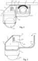
figure 2 shows a front view, in transparency, of a detail of said suction unit; -
figure 3 shows a front view of the same detail shown infigure 2 ; -
figure 4 shows an axonometric view of the same detail shown infigure 2 ; and -
figure 5 shows a further axonometric view of the same detail shown infigure 2 . - In the various figures, similar parts will be indicated with the same reference numbers.
- With reference to the attached figures, a machine M can be observed, with a
suction unit 1 according to the present invention, in particular a pass-through machine, for edging a piece P, for example, a wooden panel, comprising asuction unit 1, a workingunit 2, means 3 for handling said piece P, and a supportingplane 4 for said piece P. Machines of this type are also known in the sector as edge banding machines. - Said handling means 3 comprises a
conveyor belt 31, which allows the advancement of said piece P along an advancement direction X, so that said piece P can be subjected to various machining. In further embodiments said handling means 3 comprise a belt or transport rollers. In particular, in the edge banding machines M such as the one described in the present embodiment, the machining can be grinding, gluing the edge, end milling, trimming, gleaning the edge, rounding the edge, scraping the edge and scraping off any glue excess. These machining are carried out by specific working groups or units generally arranged in series on one side of theconveyor belt 31. In other embodiments, various series of different machining groups or units can be provided, according to the technical machining requirements. - In general, considering the woodworking machines, some working groups or units can provide for the generation of jets of shavings and dust, such as waste. In particular, said working
unit 2 comprises amachining tool 21, in particular a rotary tool, for example, a milling cutter, for machining at least one narrow side of said piece P, to perform, for example, the gleaning step, which generates a jet of waste material G during said machining. - Furthermore, near said working
unit 2 is saidsuction unit 1, to intercept, suck up and drag the machining residues, i.e., said shavings and dust, which constitute, as mentioned, said jet of waste material G. - Said
suction unit 1 comprises asuction hood 12, which has abody 121, internally hollow, so as to delineate a collection volume V, in which saidbody 121 has anentrance opening 1211, oriented so as to intercept said jet of waste material G coming, in use, from saidrotary tool 21, and arranged so as to partially surround saidrotary tool 21, an outlet opening 1212, from which said jet of waste material G is sucked, and aseat 1213 for housing saidrotary tool 21, so that saidrotary tool 21 and saidsuction hood 12 are integral, i.e. have common movement axes. - Said
suction hood 12 also comprises a deflection surface S, obtained on saidbody 121 and located so as to partially delimit said collection volume V. Said deflection surface S is inclined with respect to the direction of saidsupport surface 4, to divert said jet of waste material G, coming, when the machine M is in use, from saidrotary tool 21, towards said outlet opening 1212. - Said
suction hood 12 also comprises adiffusion unit 122, formed, in the embodiment illustrated, in saidbody 121, which has a nozzle 1221 for the entry of a flow of fluid A, in particular compressed air or air, and achamber 1222, equipped with a slottedsurface 1223, from which a diffused flow D of fluid, especially compressed air, comes out. - Said
slotted surface 1223 is oriented so that the diffused flow D is directed, in use, towards said deflection surface S, as better explained below. - In another embodiment said
diffusion unit 122 comprises a plurality of nozzles for the inlet of a fluid flow. - In a further embodiment, said
diffusion unit 122 comprises at least one nozzle, for the inlet of a fluid flow, which can be orientated, so as to vary the direction of said fluid flow. - Said
suction unit 1 also comprises anexit conduit 13, coupled to said outlet opening 1212. Furthermore, saidsuction unit 1 comprises apump 11, for sucking up said jet of waste material G, intercepted by said deflection surface S through saidexit conduit 13. - The operation of the machine M with the improved suction unit described above is as follows.
- Said piece P, which in the particular embodiment is a panel of wood or similar materials, is moved by said handling means 3 along said advancement direction X.
- In the embodiment described, the gleaning machining is of the discordant type, i.e. said
rotary tool 21, able to perform the gleaning of at least one narrow side of said piece P, rotates in the opposite direction with respect to the linear advancement motion of the panel P along the X direction, generating a jet of waste material G, therefore directed in the opposite direction with respect to the advancement direction of the panel. - Said jet of waste material G is sucked up by said
suction unit 1, through the actuation of thepump 11. In particular, the jet of waste material G enters thesuction hood 12 through theentrance opening 1211. - The jet of waste material G is thus intercepted, for the most part, by the deflection surface S, and is deflected towards the
outlet opening 1212. - Said jet of waste material G, in the embodiment illustrated, comprises chips mixed with glue used for the application of an edge to the panel P, therefore it can stick by adhesion inside the
suction hood 12, in particular on the deflection surface S. - Inside the
chamber 1222 of saiddiffusion unit 122, which, as mentioned, is integrated in thebody 121 of saidsuction hood 12, a flow of compressed air A is injected through the nozzle 1221. - Said
diffusion unit 122 diffuses said flow of compressed air A thorough said slottedsurface 1223, increasing its speed, due to the fact that the flow of compressed air A passes from a surface with a larger section, when it is in thechamber 1222, to a surface with a smaller section when it passes inside the slots of the slottedsurface 1223. - Outgoing from said slotted surface there is therefore a diffused flow D of compressed air, which is directed towards said deflection surface S of said
suction hood 12. - Said diffused flow D, impinging on said deflection surface S, ne removes any residues of said jet of waste material G, produced following processing by said
rotary tool 21, which represents a possible cause of clogging of saidsuction hood 12. - Furthermore, said diffused flow D facilitates the conveyance of said jet of waste material G, towards said
exit conduit 13 by saidpump 11, since it helps to direct it towards theopen outlet port 1212. - In a further embodiment, said deflection surface S, of said
suction hood 12, has a concavity, directed so as to intercept said jet of waste material G, to improve its deflection towards saidoutlet opening 1212 of saidsuction hood 12. - In another embodiment said
diffusion unit 122, included in saidsuction hood 12, is an element distinct from saidbody 121, made of the same material as thesuction hood 12 or in a different material. - The invention can also be used in machines of different types with respect to the one described, for example in machining centers for working pieces made of wood, plastic, composite material, or the like, in which said pieces are stationary, and at least one machining head, equipped of at least one tool, is movable in translation and/or rotation with respect to said pieces.
- An advantage of the present invention is that of avoiding the clogging of suction hoods associated with machines for processing pieces made of wood, plastic, composite materials, or other materials, equipped with rotary tools which generate a jet of waste material, such as chips, mixed with other materials, especially glue.
- Another advantage of the present invention is that of facilitating the conveyance of said jet of waste material by said suction hoods.
- The present invention has been described for illustrative but not limitative purposes, according to its preferred embodiments, but it is to be understood that modifications and/or changes can be introduced by those skilled in the art without departing from the relevant scope as defined in the enclosed claims.
Claims (14)
- Machine (M) for working a work piece (P), such as a piece made of wood, plastic, composite material or the like, comprisingat least one working tool (21), that generates a jet of waste material (G) during said working on said piece (P), andat least one suction unit (1) for suctioning said jet of waste material (G), wherein said suction unit (1) comprises a suction hood (12) havingan outlet opening (1212),a body (121), anda deflection surface (S), obtained on said body, arranged so as to intercept said jet of waste material (G),wherein said machine (M) is characterized in that said suction unit (1) comprises a diffusion unit (122) supplied by a flow of fluid (A), in particular air or compressed air, said diffusion unit (122) producing a diffused flow (D) of fluid, oriented towards said deflection surface (S), so as to remove from said deflection surface (S) any residual of said jet of waste material (G), and conveying said jet of waste material (G) towards said outlet opening (1212).
- Machine (M) according to the preceding claim, characterizedin that said body (121) defines a collection volume (V), andin that said diffusion unit (122) is arranged inside of said collection volume (V).
- Machine (M) according to any one of the preceding claims, characterized in that said suction hood (12) is arranged near said working tool (21), and has an entrance opening (1211), for collecting said jet of waste material (G).
- Machine (M) according to any one of the preceding claims, characterized in that said diffusion unit (122) comprises at least one nozzle (1221) for entering said fluid flow (A).
- Machine (M) according to any one of the preceding claims, characterized in that said diffusion unit (122) has a slotted surface (1223), for diffusing said fluid flow (A), producing said diffused flow (D) and orienting it towards said deflection surface (S), increasing its velocity.
- Machine (M) according to any one of the preceding claims, characterized in that said diffusion unit (122) has a chamber (1222).
- Machine (M) according to any one of the preceding claims, characterized in that said diffusion unit (122) is integrated in said suction hood (12).
- Machine (M) according to any one of the preceding claims, characterized in that said suction hood (1) comprisesan exit duct (13), connected to said outlet opening (1212) of said body (121) of said suction hood (12), anda pump (11) for suctioning said jet of waste material (G), intercepted by said deflection surface (S) and for conveying it towards said exit conduit (13).
- Machine (M) according to any one of the preceding claims, characterizedin that it comprises a supporting plane (4) for said piece (P), andin that said deflection surface (S) of said body (121) of said suction hood (12) is tilted with respect to said supporting plane (4) so as to deflect said jet of waste material (G) towards said outlet opening (1212).
- Machine (M) according to any one of the preceding claims, characterized in that said deflection surface (S) of said body (121) of said suction hood (12) is concave and is directed so as to intercept said jet of waste material (G) for deflecting it towards said outlet opening (1212).
- Machine (M) according to any one of the preceding claims, characterized in that said piece (P) and said working tool (21) have relative motion.
- Machine (M) according to any one of the preceding claims, characterized in that said body (121) has a seat (1213) for housing said working tool (21), so that said working tool (21) and said suction hood (12) are integral.
- Suction hood (12) for suctioning a jet of waste material (G), generated during working of pieces made of wood, plastic, composite material or the like by means of a working tool (21) havinga body (121), comprising a deflection surface (S), arranged so as to intercept, in use, said jet of waste material (G), andan entrance opening (1211) for collecting, in use, said jet of waste material (G) and an outlet opening (1212),characterized in that it comprisesa diffusion unit (122), capable of being supplied by a fluid flow (A) in particular air or compressed air, wherein said diffusion unit (122) diffuses, in use, said fluid flow (A), producing a diffused flow (D) and orienting said diffused flow (D) on said deflection surface (S), so as to remove from said deflection surface (S) any residual of said jet of waste material (G) produced as a result of the working of pieces made of wood, plastic, composite material or the like, and to convey said jet of waste material (G) towards said outlet opening (1212).
- Suction hood (12) according to the preceding claim, characterized in that said body (121) has a seat (1213) in which said working tool (21) can be housed, so that said working tool (21) and said suction hood (12) are integral.
Applications Claiming Priority (1)
| Application Number | Priority Date | Filing Date | Title |
|---|---|---|---|
| IT102021000031121A IT202100031121A1 (en) | 2021-12-13 | 2021-12-13 | Machine with improved extraction unit and improved extraction hood |
Publications (2)
| Publication Number | Publication Date |
|---|---|
| EP4194129A1 true EP4194129A1 (en) | 2023-06-14 |
| EP4194129B1 EP4194129B1 (en) | 2026-01-21 |
Family
ID=80461797
Family Applications (1)
| Application Number | Title | Priority Date | Filing Date |
|---|---|---|---|
| EP22211773.1A Active EP4194129B1 (en) | 2021-12-13 | 2022-12-06 | Suction hood and machine with suction unit |
Country Status (2)
| Country | Link |
|---|---|
| EP (1) | EP4194129B1 (en) |
| IT (1) | IT202100031121A1 (en) |
Cited By (1)
| Publication number | Priority date | Publication date | Assignee | Title |
|---|---|---|---|---|
| CN117283416A (en) * | 2023-10-13 | 2023-12-26 | 无锡盛达不锈钢热压模板有限公司 | A kind of polishing equipment for stainless steel hot pressing template processing |
Citations (4)
| Publication number | Priority date | Publication date | Assignee | Title |
|---|---|---|---|---|
| US20080006344A1 (en) * | 2006-06-20 | 2008-01-10 | Leitz Gmbh & Co. Kg | Machine tool with an exhaust hood |
| ITMO20070245A1 (en) * | 2007-07-25 | 2009-01-26 | Scm Group Spa | DEVICE |
| WO2015102906A1 (en) * | 2013-12-30 | 2015-07-09 | Robert Bosch Gmbh | Airflow managemnet system for a power tool |
| WO2020115599A1 (en) * | 2018-12-06 | 2020-06-11 | Zorka Sp. Z O.O. | A method of machining longitudinal wood-like components and a workstand to perform thereof |
-
2021
- 2021-12-13 IT IT102021000031121A patent/IT202100031121A1/en unknown
-
2022
- 2022-12-06 EP EP22211773.1A patent/EP4194129B1/en active Active
Patent Citations (4)
| Publication number | Priority date | Publication date | Assignee | Title |
|---|---|---|---|---|
| US20080006344A1 (en) * | 2006-06-20 | 2008-01-10 | Leitz Gmbh & Co. Kg | Machine tool with an exhaust hood |
| ITMO20070245A1 (en) * | 2007-07-25 | 2009-01-26 | Scm Group Spa | DEVICE |
| WO2015102906A1 (en) * | 2013-12-30 | 2015-07-09 | Robert Bosch Gmbh | Airflow managemnet system for a power tool |
| WO2020115599A1 (en) * | 2018-12-06 | 2020-06-11 | Zorka Sp. Z O.O. | A method of machining longitudinal wood-like components and a workstand to perform thereof |
Cited By (1)
| Publication number | Priority date | Publication date | Assignee | Title |
|---|---|---|---|---|
| CN117283416A (en) * | 2023-10-13 | 2023-12-26 | 无锡盛达不锈钢热压模板有限公司 | A kind of polishing equipment for stainless steel hot pressing template processing |
Also Published As
| Publication number | Publication date |
|---|---|
| EP4194129B1 (en) | 2026-01-21 |
| IT202100031121A1 (en) | 2023-06-13 |
Similar Documents
| Publication | Publication Date | Title |
|---|---|---|
| EP4194129B1 (en) | Suction hood and machine with suction unit | |
| CN101410222A (en) | Cutting or etching device with tool provided with impeller for suction of dust | |
| CN115502471B (en) | A self-cleaning dust-free table saw | |
| CN1700969A (en) | Hand-held machine tool comprising a dust box | |
| TWI393604B (en) | Machine tool with vacuum hood | |
| US20190091818A1 (en) | Apparatus with extraction device | |
| EP0458726B1 (en) | Woodworking machine, such as a traversing sanding machine | |
| CN1974093B (en) | Power tool having means for removing debris from workpiece | |
| CN210173724U (en) | Dust collector and processing machine having the same | |
| EP2022602B1 (en) | Device for removing chips in machine tools | |
| KR102173888B1 (en) | Wood processing apparatus capable of sequential cutting and grinding | |
| CN110653864A (en) | Cutter wheel cleaning mechanism and scribing device | |
| CN113613839B (en) | Dust hood device for power tool, use thereof, and dust collection method | |
| EP4129567A1 (en) | Machine for machining workpieces, with a blowing device | |
| JP3640483B2 (en) | Router processing equipment for the manufacture of gaming machines | |
| JP3210757U (en) | Wet cleaner suction head | |
| CN113732516A (en) | Machine for machining wooden workpieces comprising a laser system and method for operating the same | |
| CN108202365B (en) | Machine tool for machining edges of workpieces | |
| CN114144290A (en) | Apparatus for grooving and parting-cutting machining with chip guide function | |
| CN223998649U (en) | Linkage dust collection device | |
| US20260097443A1 (en) | Circular saw | |
| US20230138714A1 (en) | Chip guiding device | |
| JP2878668B2 (en) | Deburring method and apparatus by shot blast | |
| JPH04267107A (en) | Dicing device | |
| JPH0751250Y2 (en) | Sanding machine |
Legal Events
| Date | Code | Title | Description |
|---|---|---|---|
| PUAI | Public reference made under article 153(3) epc to a published international application that has entered the european phase |
Free format text: ORIGINAL CODE: 0009012 |
|
| STAA | Information on the status of an ep patent application or granted ep patent |
Free format text: STATUS: THE APPLICATION HAS BEEN PUBLISHED |
|
| AK | Designated contracting states |
Kind code of ref document: A1 Designated state(s): AL AT BE BG CH CY CZ DE DK EE ES FI FR GB GR HR HU IE IS IT LI LT LU LV MC ME MK MT NL NO PL PT RO RS SE SI SK SM TR |
|
| STAA | Information on the status of an ep patent application or granted ep patent |
Free format text: STATUS: REQUEST FOR EXAMINATION WAS MADE |
|
| 17P | Request for examination filed |
Effective date: 20231207 |
|
| RBV | Designated contracting states (corrected) |
Designated state(s): AL AT BE BG CH CY CZ DE DK EE ES FI FR GB GR HR HU IE IS IT LI LT LU LV MC ME MK MT NL NO PL PT RO RS SE SI SK SM TR |
|
| STAA | Information on the status of an ep patent application or granted ep patent |
Free format text: STATUS: EXAMINATION IS IN PROGRESS |
|
| 17Q | First examination report despatched |
Effective date: 20250218 |
|
| GRAP | Despatch of communication of intention to grant a patent |
Free format text: ORIGINAL CODE: EPIDOSNIGR1 |
|
| STAA | Information on the status of an ep patent application or granted ep patent |
Free format text: STATUS: GRANT OF PATENT IS INTENDED |
|
| INTG | Intention to grant announced |
Effective date: 20250924 |
|
| GRAS | Grant fee paid |
Free format text: ORIGINAL CODE: EPIDOSNIGR3 |
|
| GRAA | (expected) grant |
Free format text: ORIGINAL CODE: 0009210 |
|
| STAA | Information on the status of an ep patent application or granted ep patent |
Free format text: STATUS: THE PATENT HAS BEEN GRANTED |
|
| AK | Designated contracting states |
Kind code of ref document: B1 Designated state(s): AL AT BE BG CH CY CZ DE DK EE ES FI FR GB GR HR HU IE IS IT LI LT LU LV MC ME MK MT NL NO PL PT RO RS SE SI SK SM TR |
|
| REG | Reference to a national code |
Ref country code: CH Ref legal event code: F10 Free format text: ST27 STATUS EVENT CODE: U-0-0-F10-F00 (AS PROVIDED BY THE NATIONAL OFFICE) Effective date: 20260121 |
|
| REG | Reference to a national code |
Ref country code: DE Ref legal event code: R096 Ref document number: 602022028789 Country of ref document: DE |
|
| REG | Reference to a national code |
Ref country code: IE Ref legal event code: FG4D |