EP4194052A1 - Light irradiation device and light irradiation system - Google Patents
Light irradiation device and light irradiation system Download PDFInfo
- Publication number
- EP4194052A1 EP4194052A1 EP20948632.3A EP20948632A EP4194052A1 EP 4194052 A1 EP4194052 A1 EP 4194052A1 EP 20948632 A EP20948632 A EP 20948632A EP 4194052 A1 EP4194052 A1 EP 4194052A1
- Authority
- EP
- European Patent Office
- Prior art keywords
- light
- light irradiation
- irradiation device
- optical fiber
- optical path
- Prior art date
- Legal status (The legal status is an assumption and is not a legal conclusion. Google has not performed a legal analysis and makes no representation as to the accuracy of the status listed.)
- Withdrawn
Links
Images








Classifications
-
- A—HUMAN NECESSITIES
- A61—MEDICAL OR VETERINARY SCIENCE; HYGIENE
- A61N—ELECTROTHERAPY; MAGNETOTHERAPY; RADIATION THERAPY; ULTRASOUND THERAPY
- A61N5/00—Radiation therapy
- A61N5/06—Radiation therapy using light
- A61N5/0601—Apparatus for use inside the body
-
- A—HUMAN NECESSITIES
- A61—MEDICAL OR VETERINARY SCIENCE; HYGIENE
- A61N—ELECTROTHERAPY; MAGNETOTHERAPY; RADIATION THERAPY; ULTRASOUND THERAPY
- A61N5/00—Radiation therapy
- A61N5/06—Radiation therapy using light
- A61N5/0613—Apparatus adapted for a specific treatment
- A61N5/062—Photodynamic therapy, i.e. excitation of an agent
-
- A—HUMAN NECESSITIES
- A61—MEDICAL OR VETERINARY SCIENCE; HYGIENE
- A61B—DIAGNOSIS; SURGERY; IDENTIFICATION
- A61B18/00—Surgical instruments, devices or methods for transferring non-mechanical forms of energy to or from the body
- A61B18/18—Surgical instruments, devices or methods for transferring non-mechanical forms of energy to or from the body by applying electromagnetic radiation, e.g. microwaves
- A61B18/20—Surgical instruments, devices or methods for transferring non-mechanical forms of energy to or from the body by applying electromagnetic radiation, e.g. microwaves using laser
- A61B18/22—Surgical instruments, devices or methods for transferring non-mechanical forms of energy to or from the body by applying electromagnetic radiation, e.g. microwaves using laser the beam being directed along or through a flexible conduit, e.g. an optical fibre; Couplings or hand-pieces therefor
- A61B2018/2244—Features of optical fibre cables, e.g. claddings
-
- A—HUMAN NECESSITIES
- A61—MEDICAL OR VETERINARY SCIENCE; HYGIENE
- A61B—DIAGNOSIS; SURGERY; IDENTIFICATION
- A61B18/00—Surgical instruments, devices or methods for transferring non-mechanical forms of energy to or from the body
- A61B18/18—Surgical instruments, devices or methods for transferring non-mechanical forms of energy to or from the body by applying electromagnetic radiation, e.g. microwaves
- A61B18/20—Surgical instruments, devices or methods for transferring non-mechanical forms of energy to or from the body by applying electromagnetic radiation, e.g. microwaves using laser
- A61B18/22—Surgical instruments, devices or methods for transferring non-mechanical forms of energy to or from the body by applying electromagnetic radiation, e.g. microwaves using laser the beam being directed along or through a flexible conduit, e.g. an optical fibre; Couplings or hand-pieces therefor
- A61B2018/2255—Optical elements at the distal end of probe tips
- A61B2018/2272—Optical elements at the distal end of probe tips with reflective or refractive surfaces for deflecting the beam
-
- A—HUMAN NECESSITIES
- A61—MEDICAL OR VETERINARY SCIENCE; HYGIENE
- A61N—ELECTROTHERAPY; MAGNETOTHERAPY; RADIATION THERAPY; ULTRASOUND THERAPY
- A61N5/00—Radiation therapy
- A61N5/06—Radiation therapy using light
- A61N2005/063—Radiation therapy using light comprising light transmitting means, e.g. optical fibres
-
- A—HUMAN NECESSITIES
- A61—MEDICAL OR VETERINARY SCIENCE; HYGIENE
- A61N—ELECTROTHERAPY; MAGNETOTHERAPY; RADIATION THERAPY; ULTRASOUND THERAPY
- A61N5/00—Radiation therapy
- A61N5/06—Radiation therapy using light
- A61N2005/0632—Constructional aspects of the apparatus
-
- A—HUMAN NECESSITIES
- A61—MEDICAL OR VETERINARY SCIENCE; HYGIENE
- A61N—ELECTROTHERAPY; MAGNETOTHERAPY; RADIATION THERAPY; ULTRASOUND THERAPY
- A61N5/00—Radiation therapy
- A61N5/06—Radiation therapy using light
- A61N2005/0664—Details
- A61N2005/0665—Reflectors
Definitions
- the disclosed embodiments relate to a light irradiation device and a light irradiation system.
- PDT photodynamic therapy
- a photosensitizer is administered intravenously and then irradiated with light to generate active oxygen in cancer cells, thereby killing the cancer cells (e.g., refer to Non Patent Literature 1).
- PDT is not widely used as a treatment technique because of its low selective accumulation of photosensitizers in cancer cells and high side effects caused by intake of the photosensitizers into normal cells.
- NIR-PIT Near-infrared photoimmunotherapy
- This complex is selectively accumulated in the cancer cells in the body when administered intravenously.
- the complex is activated by being irradiated with light having an excitation wavelength (e.g., 690 nm) of the photosensitizer in the complex to exhibit an anticancer effect (e.g., refer to Patent Literature 1).
- an excitation wavelength e.g. 690 nm
- NIR-PIT In NIR-PIT, side effects can be reduced compared to PDT due to the selective accumulation of the antibodies into the cancer and local light irradiation. Further, in NIR-PIT, light irradiation (NIR irradiation) is performed in a near-infrared region of 690 nm, for example. As a result, NIR irradiation can be expected to act on the immune system (e.g., refer to Non Patent Literature 2).
- a specific wavelength range including 690 nm exemplified in the above is called the "biological optical window", and it is a wavelength range in which less light is absorbed by biological components than other wavelength ranges.
- the light irradiation from the body surface results in poor light penetration, causing a problem of not being able to apply the light to cancer deep inside the body.
- NIR-PIT in which light irradiation is performed at a position closer to cancer cells instead of performing the light irradiation from the body surface (e.g., refer to Non Patent Literature 3).
- Patent Literatures 2 and 3 disclose devices that can be used in such PDT and NIR-PIT.
- Patent Literature 4 discloses a device for obtaining a tomographic image of a biological tissue for the purpose of diagnosing the biological tissue by inserting the device into a biological lumen such as the blood vessel and emitting light transmitted via an optical fiber deep inside the body.
- an optical fiber transmits light by total reflection of light using a difference in refractive index between a core and a clad covering the outer peripheral surface of the core and emits the light from the core exposed at the distal end.
- a direction of the light irradiation is preferably a direction of the tissue surrounding the biological lumen, that is, a direction that intersects a central axis of the device (and the optical fiber).
- an optical element (prism) disposed on the distal side relative to the optical fiber is used to change an optical path of the light transmitted from the optical fiber, thereby making it possible to emit the light in the direction intersecting the central axis of the device.
- a reflection surface of the optical element used for changing the optical path is a boundary surface between the optical element and the air.
- the optical element needs to be formed in a shape sharpened from the proximal side to the distal side, causing a poor safety problem.
- the device described in Patent Literature 4 when the device is inserted into the blood vessel, for example, there is a risk of air embolism in the blood vessel. Further, when the blood enters inside the device, the air is replaced by the blood and the blood is then heated by absorption of light, which may cause blood coagulation.
- the device described in Patent Literature 4 has poor safety problems also in these points. Further, in the devices described in Patent Literature 2 and Patent Literature 3, no consideration is given for emitting the light in the direction intersecting the central axes of the devices.
- problems are not limited to PDT and NIR-PIT but are also common to all devices used in examination or treatments including a process of emitting light in the body (e.g., examination or treatments for cerebral aneurysm, arrhythmia, Alzheimer's disease, etc.).
- This light is not limited to the specific wavelength region including 690 nm as exemplified in the above but also includes infrared light in a wavelength region larger than 780 nm.
- problems are not limited to the devices inserted into the blood vessels but also common to all devices inserted into the biological lumens such as the vascular system, the lymphatic system, the biliary system, the urinary system, the respiratory system, the digestive system, the secretory glands, and the reproductive organs.
- the disclosed embodiments have been made to solve at least a part of the above-mentioned problems, and an object of the disclosed embodiments is to improve safety in a light irradiation device that can emit light from an optical fiber in a direction intersecting a central axis of the device.
- the light irradiation system separately includes the light irradiation device and the catheter having the light transmitting portion that transmits the light reflected by the boundary surface of the light irradiation device.
- the disclosed embodiments can be implemented in various aspects such as, for example, a guide wire as the light irradiation device, a catheter as the light irradiation device, a light irradiation system including the light irradiation system and the catheter, and production methods thereof.
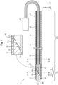
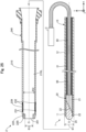
- Fig. 1 an explanatory diagram exemplifying a configuration of a light irradiation device 1 of a first embodiment.
- the light irradiation device 1 is used by being inserted into biological lumens such as the blood vessel system, the lymphatic system, the biliary system, the urinary system, the respiratory system, the digestive system, the secretory glands, and the reproductive organs.
- the light irradiation system is a device that emits light from inside the biological lumen toward the biological tissue. It is used in, for example, PDT (photodynamic therapy) and NIR-PIT (near-infrared photoimmunotherapy).
- the light irradiation device 1 of the present embodiment is a probe body including a light irradiation portion 100 that emits light LT in a lateral direction of the light irradiation device 1 (in other words, in a direction intersecting a central axis of the light irradiation device 1). As shown in Fig. 1 , the light irradiation device 1 includes the light irradiation portion 100 and an extending portion 200 from a distal side to a proximal side.
- an axis passing through the center of the light irradiation device 1 is represented by an axis O (a dash-dotted line).
- the axis O coincides with the axis passing through the center of the light irradiation device 1 and each constituent member thereof.
- the axis O may be different from the central axis of the light irradiation device 1 and each constituent member thereof.
- Fig. 1 shows mutually orthogonal X, Y, and Z axes.
- the X axis corresponds to the longitudinal direction of the light irradiation device 1 (direction of the axis O), the Y axis corresponds to the height direction of the light irradiation device 1, and the Z axis corresponds to the width direction of the light irradiation device 1.
- the left side (-X-axis direction) of Fig. 1 is referred to as a "distal side" of the light irradiation device 1 and each constituent member thereof, and the right side (+X-axis direction) of Fig. 1 is referred to as a "proximal side" of the light irradiation device 1 and each constituent member thereof.
- an end portion located on the distal side is referred to as a "distal end”, and the distal end and a vicinity thereof are referred to as a “distal portion”.
- an end portion located on the proximal side is referred to as a "proximal end”, and the proximal end and a vicinity thereof are referred to as a "proximal portion”.
- the distal side is inserted into the living body, and the proximal side is operated by an operator such as a medical doctor.
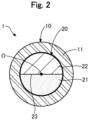
- Fig. 2 is an explanatory diagram exemplifying a cross-sectional configuration along a line A-A in Fig. 1 .
- the light irradiation portion 100 is a portion disposed on the distal side of the light irradiation device 1 and includes a light transmitting portion 11 and an optical path changing member 20.
- the optical path changing member 20 is a light transmissive member that changes an optical path of light entered from an optical fiber 80.
- the term "light transmissive” described herein means a property of transmitting light entered from the outside.
- the optical path changing member 20 is a solid, substantially cylindrical member that extends along the axis O of the light irradiation device 1 and has a substantially constant outer diameter from the proximal side to the distal side.
- the optical path changing member 20 is disposed in contact with a core of the optical fiber 80 on the distal side relative to the optical fiber 80.
- the term "contact” described herein means both a state in which the core of the optical fiber 80 and the optical path changing member 20 are disposed adjacent to each other and a state in which the core of the optical fiber 80 is embedded in the optical path changing member 20.
- the optical path changing member 20 includes a distal side member 22 and a proximal side member 21.
- the distal side member 22 is disposed on the distal side of the optical path changing member 20.
- a distal portion 24 of the distal side member 22 is formed in a curved shape having a certain radius R.
- R the radius of R given to the distal portion 24 can be freely changed, and the distal portion 24 does not have to be formed in the hemispherical shape.
- a proximal portion of the distal side member 22 has an inclined surface that is inclined relative to a vertical plane of the central axis O of the optical fiber 80 (i.e., the YZ plane along the line A-A in Fig. 1 ).
- the inclined surface of the distal side member 22 is a flat surface with no curvature.
- the distal side member 22 has a light transmitting property, and a refractive index n2 of the distal side member 22 is 1.3 or more. Note that the refractive index n2 may be less than 1.3 as long as it is greater than the refractive index of the air.
- the outer diameter and the length in the X-axis direction of the distal side member 22 can be freely determined.
- the proximal side member 21 is disposed on the proximal side of the optical path changing member 20.
- a distal portion of the proximal side member 21 has an inclined surface that is inclined, at the same angle and in the same direction as the distal side member 22, relative to the vertical plane of the central axis O of the optical fiber 80 (i.e., the YZ plane along the line A-A in Fig. 1 ).
- the inclined surface of the proximal side member 21 is a flat surface with no curvature.
- the inclined surface of the distal side member 22 and the inclined surface of the proximal side member 21 are in contact with each other to form a boundary surface 23.
- the boundary surface 23 is inclined relative to the vertical plane of the central axis O of the optical fiber 80 (i.e., the YZ plane along the line AA in Fig. 1 ).
- the core of the optical fiber 80 is in contact with a proximal portion of the proximal side member 21.
- the proximal side member 21 has the light transmitting property, and a refractive index n1 of the proximal side member 21 is 1.3 or more. Note that the refractive index n1 may be less than 1.3 as long as it is greater than the refractive index of the air.
- the outer diameter and the length in the X-axis direction of the proximal side member 21 can be freely determined. The outer diameter and the length of the proximal side member 21 may be the same as or different from those of the distal side member 22.
- an acute angle ⁇ b formed between the central axis O of the optical fiber 80 and the boundary surface 23 of the optical path changing member 20 is referred to as an "inclination angle ⁇ b of the boundary surface 23".
- the acute angle formed between the axis O and the boundary surface 23 is the same as an acute angle formed between the outer peripheral surface of the distal side member 22 and the boundary surface 23.
- either one of them may be illustrated and called the inclination angle ⁇ b of the boundary surface 23.
- the inclination angle ⁇ b of the boundary surface 23 is within a range of the following formula (1).
- NA is defined by the numerical aperture of the optical fiber 80
- n1 is defined by the refractive index of the proximal side member 21
- n2 is defined by the refractive index of the distal side member 22. 0 ⁇ ⁇ b ⁇ ⁇ /2 + arcsin NA/n1 ⁇ arcsin n2/n1
- the light transmitting portion 11 transmits the light LT reflected or refracted by the optical path changing member 20 and allows the light LT to be emitted in a direction intersecting the central axis O of the light irradiation device 1 (hereinafter also simply referred to as a "lateral direction").
- the light transmitting portion 11 is a light transmissive member formed in a substantially cylindrical shape having a substantially constant outer diameter from the proximal side to the distal side. As shown in Fig. 1 and Fig. 2 , the light transmitting portion 11 is disposed so as to cover the outer peripheral surface of the optical path changing member 20 (specifically, the distal side member 22 and the proximal side member 21).
- the outer peripheral surface of the optical path changing member 20 and the inner peripheral surface of the light transmitting portion 11 are in contact with each other. However, there may be a gap between the optical path changing member 20 and the light transmitting portion 11.
- the outer diameter and the inner diameter of the light transmitting portion 11 can be freely determined.
- the optical path changing member 20 can be formed by molding a transparent or translucent UV-curable resin into the above-mentioned shape and curing it with UV rays.
- UV curable resins having the different refractive indices may be used as materials.
- the optical path changing member 20 (the proximal side member 21 and the distal side member 22) may be achieved by an optical element such as a prism.
- the light transmitting portion 11 can be formed of a resin material having the light-transmitting property, for example, a polyolefin such as polyethylene, polypropylene, or an ethylene-propylene copolymer, a polyester such as polyethylene terephthalate, a thermoplastic resin such as polyvinyl chloride or polyurethane, or the like.
- a resin material having the light-transmitting property for example, a polyolefin such as polyethylene, polypropylene, or an ethylene-propylene copolymer, a polyester such as polyethylene terephthalate, a thermoplastic resin such as polyvinyl chloride or polyurethane, or the like.
- the optical path changing member 20 is preferably constituted as a transparent member from the viewpoint of improving the light transmitting property.
- transparent member described herein refers to a member that transmits light without absorbing or scattering the light.
- the optical path changing member 20 (the proximal side member 21 and the distal side member 22) may be constituted by using a material with the relatively large refractive indices n1 and n2, such as, for example, silicon or germanium.
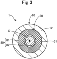
- Fig. 3 is an explanatory diagram exemplifying a cross-sectional configuration along a line B-B in Fig. 1 .
- the extending portion 200 is a portion disposed on the proximal side of the light irradiation device 1 (the proximal side relative to the light irradiation portion 100) and includes the optical fiber 80, a main body portion 12, and a joint portion 31.
- the optical fiber 80 transmits laser light (also simply referred to as "light") from a light source 3.
- the optical fiber 80 is a solid cable that extends along the axis O of the light irradiation device 1 and has a substantially constant outer diameter from the proximal side to the distal side.
- the optical fiber 80 includes a core 81 extending along the axis O and a clad 82 covering the outer peripheral surface of the core 81.
- the core 81 is disposed substantially in the center of the clad 82 and has the higher optical refractive index than the clad 82.
- the clad 82 has the uniform refractive index.
- the optical fiber 80 transmits the light from the light source 3 by total reflection of the light using the refractive index difference between the core 81 and the clad 82. As shown in Fig. 1 , at the distal end of the optical fiber 80, the optical fiber 80 is cut along a plane perpendicular to the axis O to expose the core 81. The distal portion of the optical fiber 80 is fixed with the exposed core 81 and the proximal side member 21 adjacent to each other. A proximal portion of the optical fiber 80 is connected to the light source 3 disposed outside via a connector, another optical fiber, or the like.
- the light source 3 is a laser light generator that generates laser light of any wavelength.
- the optical fiber 80 of the present embodiment is a plastic optical fiber in which both the core 81 and the clad 82 are made of a resin.
- the core 81 can be formed of, for example, polymethylmethacrylate (PMMA), polystyrene, polycarbonate, a deuterated polymer, a fluorine-based polymer, a silicon-based polymer, a norbornene-based polymer, or the like.
- PMMA polymethylmethacrylate
- the core 81 is classified into a single mode and a multimode according to the number of modes in which light propagates. Either of which may be used in the present embodiment. Further, in the case of multimode, it is classified into step index and graded index according to the refractive index distribution. Either of which may be used in the present embodiment.
- the clad 82 can be formed of, for example, a fluorine-based polymer.
- the optical fiber 80 instead of the plastic optical fiber, a quartz glass optical fiber or a multi-component glass optical fiber may be employed.
- the length of the optical fiber 80 can be freely determined. Further, the optical fiber 80 may be formed only with the core 81 or further include one or more protective layers covering the clad 82.
- the main body portion 12 covers the optical fiber 80.
- the main body portion 12 is a hollow member having an elongated outer shape and disposed along the axis O.
- the lumen of the main body portion 12 accommodates the entire optical fiber 80 except for the proximal side thereof.
- the main body portion 12 preferably has anti-thrombogenicity, flexibility, and biocompatibility and can be formed of a resin material or a metal material.
- the resin material for example, a polyamide resin, a polyolefin resin, a polyester resin, a polyurethane resin, a silicon resin, a fluorine resin, or the like can be adopted.
- the metal material for example, stainless-steel such as SUS304, a nickel-titanium alloy, a cobalt-chromium alloy, tungsten steel, or the like can be adopted.
- the outer diameter, the inner diameter, and the length of the main body portion 12 can be freely determined.
- the joint portion 31 fixes the optical fiber 80 inside the main body portion 12.
- the joint portion 31 is a layer of an adhesive filled between the inner peripheral surface of the main body portion 12 and the outer peripheral surface of the optical fiber 80.
- the joint portion 31 can be formed by any bonding agent, for example, metal solder such as silver solder, gold solder, zinc, an Sn-Ag alloy, or an Au-Sn alloy, or an adhesive such as an epoxy-based adhesive. Note that, in the example in Fig. 1 , the joint portion 31 is disposed over the entire main body portion 12 in the X-axis direction.
- the joint portion 31 may be disposed only in a part of the main body portion 12 in the X-axis direction (e.g., a part of the main body portion 12 on the distal side, a part of the main body portion 12 on the proximal side, etc.). Further, the joint portion 31 may be omitted.
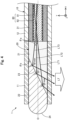
- Fig. 4 is a diagram illustrating how the light irradiation device 1 is used. Note that, for convenience of illustration, Fig. 4 shows only a fraction of the light entering the optical path changing member 20 from the optical fiber 80.
- the light irradiation device 1 is used, for example, as follows. First, an operator inserts the light irradiation device 1 into the biological lumen such as the blood vessel. The operator pushes the light irradiation device 1 forward in the biological lumen and delivers the light irradiation portion 100 to a target site for light irradiation. In this operation, the operator may deliver the light irradiation device 1 using a catheter, an endoscope, or the like, not shown. After that, the operator turns on the light source 3. Laser light generated by the light source 3 is transmitted from the proximal side to the distal side of the optical fiber 80 via the core 81 of the optical fiber 80.
- Fig. 4 shows a light LT2 that has entered the optical path changing member 20 in parallel with the axis O and lights LT1 and LT3 that have entered the optical path changing member 20 at the maximum divergence angles ⁇ a of the optical fiber 80 out of light transmitted via the optical fiber 80.
- the incident angle of the incident light LT2 parallel to the axis O relative to the boundary surface 23 is represented by ⁇ 1.
- the boundary surface 23 of the optical path changing member 20 is inclined from the -Y-axis direction toward the +Y-axis direction when viewed along the X-axis direction.
- the incident light LT1 that has been entered at the maximum divergence angle ⁇ a in the -Y-axis direction enters the boundary surface 23 at the maximum incident angle ⁇ max.
- the incident light LT3 that has been entered at the maximum divergence angle ⁇ a in the +Y-axis direction enters the boundary surface 23 at the minimum incident angle ⁇ min. That is, the incident angles of the lights LT1 to LT3 are in a range of ⁇ min ⁇ 1 ⁇ max.
- the actual value of the maximum divergence angle ⁇ a is determined by the numerical aperture NA of the optical fiber 80 and the refractive index n1 of the proximal side member 21.
- the incident lights LT1 to LT3 entering the boundary surface 23 are totally reflected by the boundary surface 23 when the incident angles ⁇ min, ⁇ 1, and ⁇ max are larger than a critical angle ⁇ c.
- the critical angle ⁇ c is determined by the refractive index n1 of the proximal side member 21 and the refractive index n2 of the distal side member 22 according to Snell's law.
- This can satisfy "minimum incident angle ⁇ min>critical angle ⁇ c", and, as a result, all the incident lights LT1 to LT3 from the optical fiber 80 are totally reflected by the boundary surface 23 and emitted to the lateral side of the light irradiation device 1 as the light LT. ( Fig. 4 ).
- the inclination angle ⁇ b is equal to or less than the upper limit value of the formula (1), it can satisfy "maximum incident angle ⁇ max>critical angle ⁇ c".
- the incident light LT1 with the maximum incident angle ⁇ max is totally reflected by the boundary surface 23 and emitted to the lateral side of the light irradiation device 1 as the light LT.
- the incident lights LT3 and LT2 with the minimum incident angle ⁇ min and the incident angle ⁇ 1, respectively, are not totally reflected but refracted by the boundary surface 23.
- the light irradiation device 1 of the present embodiment by setting the inclination angle ⁇ b of the boundary surface 23 within the range of the formula (1), some or all of the lights LT1 to LT3 entering the boundary surface 23 from the optical fiber 80 can be totally reflected and emitted to the lateral side of the light irradiation device 1.
- the actual value of the inclination angle ⁇ b will be examined in a case where the laser light generated by the light source 3 is the whole light including visible light and a case where it is infrared light.
- visible light described herein means light with a wavelength ⁇ in a range of 380 nm ⁇ wavelength ⁇ 780 nm
- infrared light means light with the wavelength ⁇ in a range of 780 nm ⁇ wavelength ⁇ 1 mm.
- Fig. 5 and Fig. 6 are diagrams for describing the inclination angle ⁇ b of the boundary surface in the case where the whole light including the visible light is used.
- the numerical aperture NA of the currently available optical fiber 80 is 0.1 or more and 0.5 or less regardless of modes (single mode and multimode).
- the refractive index of the optical path changing member 20 (the proximal side member 21 and the distal side member 22) capable of transmitting the whole light including the visible light needs to be 1.3 or more and 2.0 or less. Based on these, the following conditions a1 and a2 are assumed as preconditions here. 0.1 ⁇ NA ⁇ 0 .5 1.3 ⁇ n2 ⁇ n1 ⁇ 2 .0
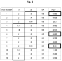
- Fig. 5 shows the inclination angles ⁇ b of the boundary surface 23 obtained by the formula (1) while changing the refractive index n1 of the proximal side member 21, the refractive index n2 of the distal side member 22, and the numerical aperture NA of the optical fiber 80 within the ranges of the conditions a1 and a2.
- Fig. 5 shows values rounded to second decimal places.
- the numerical aperture NA of the optical fiber 80 was set to the upper limit value of 0.5
- item number 7 to 12 the numerical aperture NA of the optical fiber 80 was set to the lower limit value of 0.1.
- the refractive index n1 of the proximal side member 21 was fixed at the upper limit value of 2, and the refractive index n2 of the distal side member 22 was changed within the range of the condition a2.
- the refractive index n2 of the distal side member 22 was fixed at the lower limit value of 1.3, and the refractive index n1 of the proximal side member 21 was changed within the range of the condition a2.
- the lower limit value of the inclination angle ⁇ b of the boundary surface 23 was obtained when the numerical aperture NA had the lower limit value of 0.1 and the difference between the refractive index n1 of the proximal side member 21 and the refractive index n2 of the distal side member 22 (n1-n2) was the smallest. Further, it was found that the lower limit value of the inclination angle ⁇ b of the boundary surface 23 was 8.59°.
- the numerical aperture NA and the refractive indices n1 and n2 are each obtained as values rounded to second decimal places, thus the obtained inclination angle ⁇ b is not a precise value.
- the inclination angle ⁇ b of the boundary surface 23 is preferably in a range of 0° ⁇ b ⁇ 64° in order for at least a fraction of the whole light including the visible light to be totally reflected by the boundary surface 23.
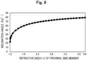
- Fig. 7 and Fig. 8 are diagrams for describing the inclination angle ⁇ b of the boundary surface when the infrared light is used.
- the numerical aperture NA of the currently available optical fiber 80 is 0.1 or more and 0.5 or less regardless of modes.
- the refractive index of the optical path changing member 20 (the proximal side member 21 and the distal side member 22) capable of transmitting the infrared light needs to be 1.3 or more and 4.0 or less.
- the following conditions b1 and b2 are assumed as preconditions here. 0.1 ⁇ NA ⁇ 0.5 1.3 ⁇ n2 ⁇ n1 ⁇ 4.0
- Fig. 7 shows the inclination angles ⁇ b of the boundary surface 23 obtained by the formula (1) while changing the refractive index n1 of the proximal side member 21, the refractive index n2 of the distal side member 22, and the numerical aperture NA of the optical fiber 80 within the ranges of the conditions b 1 and b2. Note that Fig. 7 shows values rounded to second decimal places. In item number 21 to 26, the numerical aperture NA of the optical fiber 80 was set to the upper limit value of 0.5, and, in item number 27 to 32, the numerical aperture NA of the optical fiber 80 was set to the lower limit value of 0.1.
- the refractive index n1 of the proximal side member 21 was fixed at the upper limit value of 4, and the refractive index n2 of the distal side member 22 was changed within the range of the condition b2.
- the refractive index n2 of the distal side member 22 was fixed at the lower limit value of 1.3, and the refractive index n1 of the proximal side member 21 was changed within the range of the condition b2.
- NA the numerical aperture NA and the refractive indices n1 and n2 are each obtained as values rounded to second decimal places, thus the obtained inclination angle ⁇ b is not a precise value.
- the inclination angle ⁇ b of the boundary surface 23 is preferably in a range of 0° ⁇ b ⁇ 79° in order for at least a fraction of the infrared light in the range of 780 nm ⁇ wavelength ⁇ 1 mm to be reflected by the boundary surface 23.
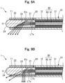
- Figs. 9A and 9B are diagrams for describing reflected light and refracted light according to the inclination angle ⁇ b of the boundary surface.
- Fig. 9A shows how all of the incident lights are totally reflected by the boundary surface 23
- Fig. 9B shows how some of the incident lights are totally reflected by the boundary surface 23.
- FIG. 9A shows how shown in FIG.
- the optical path changing member 20 includes the boundary surface 23 where the proximal side member 21 and the distal side member 22 are in contact with each other and which is inclined relative to the vertical plane of the central axis O of the optical fiber 80 (YZ plane along the line A-A in Fig. 1 ).
- the optical path changing member 20 changes the optical path of the light entered from the optical fiber 80 by using the boundary surface 23. In this manner, the light from the optical fiber 80 can be emitted in the direction intersecting the central axis O of the light irradiation device 1 without bending the optical fiber 80, in other words, while reducing the light loss that occurs when the optical fiber 80 is bent.
- the boundary surface 23 that changes the optical path of the light entered from the optical fiber 80 is a surface where the proximal side member 21 and the distal side member 22 are in contact with each other.
- the proximal side member 21 and the distal side member 22 are constituted by the member having the light transmitting property, there is no risk that the proximal side member 21 and the distal side member 22 absorb the light and generate heat.
- the device is excellent in safety.
- the distal portion 24 of the distal side member 22 is formed in the shape with high safety (e.g., a curved shape having a certain radius R as shown in Fig. 4 ), which can further improve the safety of the light irradiation device 1 inserted into the biological lumen.
- the optical path changing member 20 having the distal side member 22 on the distal side of the boundary surface 23 it is possible to improve the strength of the distal side of the optical path changing member 20 and prevent a damage to the optical path changing member 20.
- the boundary surface 23 that changes the optical path of the light entered from the optical fiber 80 is the flat surface inclined relative to the vertical plane of the central axis O of the optical fiber 80 (YZ plane along the line A-A in Fig. 1 ).
- the light entered from the optical fiber 80 can be easily totally reflected by the boundary surface 23 by adjusting the inclination angle ⁇ b of the boundary surface 23.
- the boundary surface 23, irradiated with the light from the optical fiber 80, is formed in the flat surface, so that there is little effect of axial misalignment of the optical fiber 80 in the light irradiation device 1, and the proximal side member 21 and the distal side member 22 can be easily produced.
- the distal portion 24 of the distal side member 22 disposed on the distal side of the boundary surface 23 is formed in the curved shape having a certain radius R.
- the safety of the light irradiation device 1 can be improved as compared with a case where the optical element is formed in a shape sharpened from the proximal side toward the distal side, for example.
- Fig. 10 is an explanatory diagram exemplifying a cross-sectional configuration of a light irradiation device 1A of a second embodiment along the line A-A ( Fig. 1 ).
- the light irradiation device 1A of the second embodiment includes an optical path changing member 20A instead of the optical path changing member 20 in the configuration of the first embodiment.
- the optical path changing member 20A is, as shown in the drawing, a substantially square prism-shaped solid member having a substantially constant outer diameter from the proximal side to the distal side.
- the optical path changing member 20A includes a distal side member 22A and a proximal side member 21A.
- the configurations of the distal side member 22A and the proximal side member 21A are the same as those of the first embodiment except for the shape.
- the configuration of the optical path changing member 20A can be modified in various ways, and the optical path changing member 20A may be formed in a shape other than the substantially cylindrical shape.
- the shape of the optical path changing member 20A may be the substantially square prism shape shown in Fig. 10 or a substantially polygonal prism shape.
- one of the proximal side member 21A and the distal side member 22A may be formed in the shape described in the first embodiment, and the other may be formed in the shape described in the second embodiment.
- the light irradiation device 1A of the second embodiment as described above, the same effects as those of the above-mentioned first embodiment can be achieved.
- the emission surface of the reflected light LT reflected by the boundary surface 23 can be made flat as shown in Fig. 10 , so that the emitted light can be dispersed.
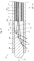
- Fig. 11 is an explanatory diagram exemplifying a configuration of a light irradiation device 1B of a third embodiment.
- the light irradiation device 1B of the third embodiment includes an optical path changing member 20B instead of the optical path changing member 20 in the configuration of the first embodiment.
- the optical path changing member 20B forms a boundary surface 23B by the contact between a distal side member 22B disposed on the distal side and a proximal side member 21B disposed on the proximal side.
- the boundary surface 23B has a flat surface in the central part and a curved surface in an outer peripheral part in the YZ-axis direction.
- the term "central part” described herein means a part irradiated with the incident light LT1 (light with the maximum incident angle ⁇ max), LT2 (light parallel to the axis O), and LT3 (light with the minimum incident angle ⁇ min) from the optical fiber 80.
- the "outer peripheral part” means a part not irradiated with the incident lights LT1 to LT3 from the optical fiber 80. That is, in the boundary surface 23B of the third embodiment, only the flat surface that is inclined relative to the vertical plane of the central axis O of the optical fiber 80 is irradiated with the light from the optical fiber 80.
- Fig. 11 shows a virtual line VL extended from the flat part of the boundary surface 23B to represent the inclination angle ⁇ b of the boundary surface 23B.
- the configuration of the optical path changing member 20B can be modified in various ways, and the optical path changing member 20B may be formed such that at least a part (central part) of the boundary surface 23B, irradiated with the lights LT1 to LT3 from the optical fiber 80, is made as a flat surface and other parts not irradiated with the lights LT1 to LT3 are made as a curved surface.
- the light irradiation device 1B of the third embodiment as described above, the same effects as those of the above-mentioned first embodiment can be achieved.
- the light irradiation device 1B of the third embodiment it is possible to increase the contact area between the proximal side member 21B and the distal side member 22B, making it possible to provide the optical path changing member 20B that is even less likely to be damaged.
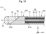
- Fig. 12 is an explanatory diagram exemplifying a configuration of a light irradiation device 1C of a fourth embodiment.
- the light irradiation device 1C of the fourth embodiment includes a shaft 10C instead of a shaft 10 and an optical path changing member 20C instead of the optical path changing member 20 in the configuration of the first embodiment.
- the shaft 10C does not include the light transmitting portion 11 ( Fig. 1 ) that covers the optical path changing member 20, and the optical path changing member 20C is exposed to the outside.
- an outer diameter ⁇ 10 of the shaft 10C (main body portion 12) is equal to an outer diameter ⁇ 20 of the optical path changing member 20C.
- the term "equal" means that a difference due to a manufacturing error is allowed.
- the outer diameter ⁇ 10 and the outer diameter ⁇ 20 may be different from each other.
- the configurations of the shaft 10C and the optical path changing member 20C can be modified in various ways.
- the shaft 10C may not cover the optical path changing member 20C and the optical path changing member 20C may be exposed to the outside.
- the same effects as those of the above-mentioned first embodiment can be achieved.
- the light irradiation device 1C of the fourth embodiment since the light is not transmitted through the light transmitting portion 11, it becomes possible to prevent the light loss due to the light being transmitted through the light transmitting portion 11, making it possible to increase the light output of the light emitted from the light irradiation device 1C to the biological tissue.
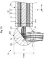
- Fig. 13 is an explanatory diagram exemplifying a configuration of a light irradiation device 1D of a fifth embodiment.
- the light irradiation device 1D of the fifth embodiment includes an optical path changing member 20D instead of the optical path changing member 20C in the configuration of the fourth embodiment.
- the optical path changing member 20D is formed in a substantially spherical shape configured by a hemispherical distal side member 22D and a hemispherical proximal side member 21D.
- a region 25 of the outer peripheral surface of the proximal side member 21D, through which the reflected light LTc reflected by the boundary surface 23 passes, is formed in a spherical shape.
- the reflected light LTc reflected by the boundary surface 23 is refracted in the spherical region 25 and condensed.
- the outer diameter ⁇ 10 of the shaft 10C (main body portion 12) is smaller than an outer diameter ⁇ 20D of the optical path changing member 20.
- the outer diameter ⁇ 10 and the outer diameter ⁇ 20D may be the same, or the outer diameter ⁇ 10 may be larger than the outer diameter ⁇ 20D.
- the configuration of the optical path changing member 20D can be modified in various ways, and the optical path changing member 20D may be formed in the substantially spherical shape.
- the same effects as those of the above-mentioned first embodiment and fourth embodiment can be achieved.
- the region 25 of the outer peripheral surface of the proximal side member 21D, through which the reflected light LTc reflected by the boundary surface 23 passes, is formed in the spherical shape, thus the reflected light LTc that has passed through the spherical surface can be condensed.
- the optical path changing member 20D formed in the substantially spherical shape can further reduce a risk of damaging the biological tissue, making it possible to further improve the safety.
- the reflected light LTc is condensed by using the spherical region 25.
- the reflected light LTc may be collimated (an optical adjustment to obtain parallel light) by using the spherical region 25.
- the light irradiation device 1D of the fifth embodiment it becomes possible to control the irradiation range of the light emitted to the biological tissue.
- Fig. 14 is an explanatory diagram exemplifying a configuration of a light irradiation device 1E of a sixth embodiment.
- the light irradiation device 1E of the sixth embodiment includes an optical path changing member 20E instead of the optical path changing member 20C in the configuration of the fourth embodiment.
- the optical path changing member 20E includes a proximal side member 21E instead of the proximal side member 21.
- the outer peripheral surface of the proximal side member 21E on the side through which the reflected light by the boundary surface 23 passes ( Fig. 14 : -Y-axis direction) is formed as a protruding portion 26 that protrudes in a spherical shape.
- the reflected light reflected by the boundary surface 23 is refracted and condensed on the surface of the protruding portion 26 as in Fig. 13 .
- the configuration of the optical path changing member 20E can be modified in various ways, and the proximal side member 21E of the optical path changing member 20E may include the protruding portion 26 that protrudes in the spherical shape.
- the protruding portion 26 is disposed only in a part of the outer peripheral surface of the proximal side member 21E ( Fig. 14 : -Y-axis direction).
- the protruding portion 26 may be disposed on the entire outer peripheral surface of the proximal side member 21E.
- Fig. 15 is an explanatory diagram exemplifying a configuration of a light irradiation device 1F of a seventh embodiment.
- the light irradiation device 1F of the seventh embodiment includes an optical path changing member 20F instead of the optical path changing member 20 in the configuration of the first embodiment and further includes a distal tip 32.
- the optical path changing member 20F includes a distal side member 22F instead of the distal side member 22.
- a distal portion of the distal side member 22F is not formed in a curved shape, and the distal portion of the distal side member 22F is formed in a flat surface parallel to the vertical plane of the central axis O of the optical fiber 80.
- the distal tip 32 joins the distal portion of the distal side member 22F and a distal portion of the shaft 10 (light transmitting portion 11) and holds them integrally.
- the distal tip 32 preferably has flexibility and can be formed of, for example, a resin material such as polyurethane or a polyurethane elastomer. Note that the distal tip 32 may be formed of a radiopaque material.
- the configuration of the light irradiation device 1F can be modified in various ways, and the light irradiation device 1F may include the distal tip 32 which joins the shaft 10 and the optical path changing member 20F and advances in the biological lumen ahead of the shaft 10 and the optical path changing member 20F.
- the distal tip 32 may be composed only of a resin member or may be composed of a combination of a coil body obtained by spirally winding a wire and a resin member.
- Fig. 16 is an explanatory diagram exemplifying a configuration of a light irradiation device 1G of an eighth embodiment.
- the light irradiation device 1G of the eighth embodiment includes a shaft 10G instead of the shaft 10 in the configuration of the first embodiment and further includes a marker 33.
- the shaft 10G includes a light transmitting portion 11G instead of the light transmitting portion 11.
- the radiopaque marker 33 is embedded in a thick part of the light transmitting portion 11G so as to surround in the circumferential direction (YZ-axis direction).
- the marker 33 is used to identify a distal portion of the light irradiation device 1G with an X-ray image.
- the marker 33 is preferably disposed in a part of the light transmitting portion 11G on the distal side.
- the marker 33 can be formed of a radiopaque resin material or metal material.
- the marker 33 in a case of using a resin material, can be formed by mixing a radiopaque material such as bismuth trioxide, tungsten, or barium sulfate with a polyamide resin, a polyolefin resin, a polyester resin, a polyurethane resin, a silicon resin, or a fluorine resin.
- a radiopaque material such as bismuth trioxide, tungsten, or barium sulfate
- a polyamide resin such as bismuth trioxide, tungsten, or barium sulfate
- a polyamide resin such as bismuth trioxide, tungsten, or barium sulfate
- a polyamide resin such as bismuth trioxide, tungsten, or barium sulfate
- a polyamide resin such as bismuth trioxide, tungsten, or barium sulfate
- the configuration of the light irradiation device 1G can be modified in various ways, and the light irradiation device 1G may include the marker 33.
- the shape of the marker 33 can be modified in various ways, and a spiral shape, a slit shape, a mesh shape, or the like can be adopted in addition to the annular shape shown in Fig. 16 .
- second and third markers may be disposed at a location different from the distal portion of the light transmitting portion 11G (e.g., the proximal portion of the light transmitting portion 11G, the distal portion of the main body portion 12, the substantially central part of the main body portion 12, etc.).
- the same effects as those of the above-mentioned first embodiment can be achieved. Further, according to the light irradiation device 1G of the eighth embodiment, the distal portion of the light irradiation device 1G can be identified with the X-ray image, so that the usability of the light irradiation device 1G can be improved.
- Fig. 17 is an explanatory diagram exemplifying a configuration of a light irradiation device 1H of a ninth embodiment.
- the light irradiation device 1H of the ninth embodiment includes a shaft 10H instead of the shaft 10 in the configuration of the first embodiment and further includes a coil body 40.
- the shaft 10H includes a main body portion 12H instead of the main body portion 12.
- the coil body 40 is embedded in a thick part of the main body portion 12H.
- the coil body 40 is formed by spirally winding an elongated wire 41 in the circumferential direction (YZ-axis direction).
- the coil body 40 is a single-strand coil formed by winding the single wire 41 into a single strand.
- the coil body 40 may be a multi-strand coil formed by winding a plurality of the wires 41 in multiple strands, a single strand twisted coil formed by winding a twisted wire consisting of multiple wires into a single strand, or a multi-strand twisted coil formed by winding multiple twisted wires each consisting of multiple wires in multiple strands.
- the wire 41 can be formed of, for example, a stainless-steel alloy such as SUS304 or SUS316, a super-elastic alloy such as a nickel-titanium alloy, a piano wire, a radiolucent alloy such as a nickel-chromium alloy or a cobalt alloy, or a radiopaque alloy such as, gold, platinum, tungsten, or an alloy containing these elements (e.g., a platinum-nickel alloy).
- the wire diameter of the wire 41 and the outer diameter and the inner diameter of the coil body 40 can be freely determined.
- the configuration of the light irradiation device 1H can be modified in various ways, and the light irradiation device 1H may include the coil body 40 to reinforce the shaft 10H.
- the coil body 40 is embedded in the thick part of the main body portion 12H.
- the coil body 40 may be embedded in a thick part of the light transmitting portion 11 or may be embedded in both the light transmitting portion 11 and the main body portion 12H.
- a mesh body formed by weaving the wires 41 may be provided.
- Fig. 18 is an explanatory diagram exemplifying a configuration of a light irradiation device 1I of a tenth embodiment.
- Fig. 19 is an explanatory diagram exemplifying a cross-sectional configuration along a line C-C in Fig. 18 .
- the light irradiation device 1I of the tenth embodiment further includes a core 50 in the configuration of the first embodiment.
- the core 50 is a reinforcing member that prevents bending of the light irradiation device 1I.
- the core 50 is an elongated wire extending along the axis O and disposed side by side with the optical fiber 80 inside the main body portion 12 ( Fig. 19 ).
- the core 50 may be formed of any hard resin material such as reinforced plastic (PEEK), or it may be formed of a stainless-steel alloy such as SUS304 or SUS316, a super-elastic alloy such as a nickel-titanium alloy, a piano wire, or a radiolucent alloy such as a nickel-chromium alloy or a cobalt alloy.
- PEEK reinforced plastic
- the configuration of the light irradiation device 1I can be modified in various ways, and the light irradiation device 1I may include the reinforcing member (core 50) for preventing the bending of the light irradiation device 1I.
- the core 50 may be a solid wire as shown in the drawing or a hollow tubular body.
- the bending of the light irradiation device 1I can be prevented, and, in addition, the torque transmissibility and durability of the light irradiation device 1I can be improved.
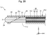
- Fig. 20 is an explanatory diagram exemplifying a configuration of a light irradiation device 1J of an eleventh embodiment.
- the light irradiation device 1J of the eleventh embodiment includes a shaft 10J instead of the shaft 10 in the configuration of the first embodiment.
- the shaft 10J includes a light transmitting portion 11J instead of the light transmitting portion 11 and a main body portion 12J instead of the main body portion 12.
- a distal side of the main body portion 12J covers a part of the outer peripheral surface of the optical path changing member 20 (specifically, the part excluding the light transmitting portion 11J).
- the light transmitting portion 11J is an opening formed in a part of the main body portion 12J on the distal side thereof covering the outer peripheral surface of the optical path changing member 20, through which the reflected light reflected by the boundary surface 23 passes.
- the reflected light reflected by the boundary surface 23 is emitted to the outside through the opening (i.e., the light transmitting portion 11J) of the main body portion 12J.
- the configuration of the shaft 10J can be modified in various ways, and the light transmitting portion 11J may be the opening formed in the main body portion 12J.
- the main body portion 12J may be formed of a light transmissive resin material, and a part of the main body portion 12J may function as the light transmitting portion 11J.
- a thin part (part with a small thickness) may be formed in the main body portion 12J, and the thin part may function as the light transmitting portion 11J.
- Fig. 21 is an explanatory diagram exemplifying a configuration of a light irradiation device 1K of a twelfth embodiment.
- Fig. 22 is an explanatory diagram exemplifying a cross-sectional configuration along a line D-D in Fig. 21 .
- the light irradiation device 1K of the twelfth embodiment further includes an inner shaft 60 in the configuration of the first embodiment.
- the inner shaft 60 is a member that constitutes a device lumen 60L for inserting a combined device such as a guide wire into the light irradiation device 1K.
- the inner shaft 60 is a substantially cylindrical member that extends along the axis O and has a substantially constant outer diameter from the proximal side to the distal side.
- the inner shaft 60 is disposed side by side with the optical fiber 80 inside the light transmitting portion 11 and the main body portion 12 ( Fig. 21 ).
- the inner shaft 60 preferably has anti-thrombogenicity, flexibility, and biocompatibility and can be formed of the same material as the main body portion 12, for example.
- the configuration of the light irradiation device 1K can be modified in various ways and, the light irradiation device 1K may include the device lumen 60L. Although one device lumen 60L is shown in the example in Fig. 21 , the light irradiation device 1K may include a plurality of the device lumens 60L. With the light irradiation device 1K of the twelfth embodiment as described above, the same effects as those of the above-mentioned first embodiment can be achieved.
- the light irradiation device 1K of the twelfth embodiment since the guide wire can be inserted into the device lumen 60L from a distal opening 61 of the device lumen 60L, the light irradiation device 1K can be easily delivered using the guide wire. As a result, the usability of the light irradiation device 1K can be improved.
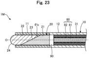
- Fig. 23 is an explanatory diagram exemplifying a configuration of a light irradiation device 1M of a thirteenth embodiment.
- the light irradiation device 1M of the thirteenth embodiment further includes a spacing portion 90 in the configuration of the first embodiment.
- the spacing portion 90 is a portion having the light transmitting property, which is disposed between the optical fiber 80 and the optical path changing member 20 in the longitudinal direction of the light irradiation device 1M.
- the spacing portion 90 transmits the light entered from the optical fiber 80 to the optical path changing member 20.
- the spacing portion 90 is a layer of the air.
- the spacing portion 90 can be formed of gas other than the air, liquid, a light transmissive resin, or the like. Further, it is preferable that both adjacent surfaces of the spacing portion 90 (i.e., a proximal surface of the proximal side member 21 and a distal surface of the core 81) are perpendicular to the central axis of the optical fiber 80.
- the configuration of the light irradiation device 1M can be modified in various ways, and the spacing portion 90 may be disposed between the optical fiber 80 and the optical path changing member 20.
- the spacing portion 90 is disposed inside the main body portion 12.
- the spacing portion 90 may be disposed inside the light transmitting portion 11.
- the same effects as those of the above-mentioned first embodiment can be achieved.
- the light irradiation device 1M of the thirteenth embodiment when a material having relatively low rigidity such as gas or liquid is used for the spacing portion 90, a part provided with the spacing portion 90 can be easily deformed. This can improve the followability of the light irradiation device 1M inside the curved biological lumen.
- a rigidity gap of the light irradiation device 1M can be made smaller than a case where the spacing portion 90 is not provided. Specifically, in the case where the spacing portion 90 is not provided, the rigidity of the light irradiation device 1 changes at the boundary between the optical fiber 80 and the optical path changing member 20. On the other hand, in the case of the present embodiment, the rigidity of the light irradiation device 1M changes at the boundary between the optical fiber 80 and the spacing portion 90, and the rigidity of the light irradiation device 1M changes at the boundary between the spacing portion 90 and the optical path changing member 20.
- the rigidity of the spacing portion 90 between the rigidity of the optical fiber 80 and the rigidity of the optical path changing member 20 can be gradually changed.
- stress concentration when the light irradiation device 1M is bent can be reduced, and a damage to the light irradiation device 1M can be prevented.
- the deformable amount of the light irradiation device 1M when the light irradiation device 1M is bent can be increased, the followability of the light irradiation device 1M in the curved biological lumen can be improved.
- Fig. 24 is an explanatory diagram exemplifying a configuration of a light irradiation device 1N of a fourteenth embodiment.
- the light irradiation device 1N of the 14th embodiment includes a spacing portion 90N instead of the spacing portion 90 in the configuration of the thirteenth embodiment.
- the spacing portion 90N includes a first spacing portion 91 disposed adjacent to the optical path changing member 20 and a second spacing portion 92 disposed adjacent to the optical fiber 80.
- the first spacing portion 91 and the second spacing portion 92 can be formed of any material with the light transmitting property.
- the first spacing portion 91 and the second spacing portion 92 may be formed of the air, gas other than the air, liquid, a light transmissive resin, or the like, as in the thirteenth embodiment.
- the rigidity of the first spacing portion 91 is preferably an intermediate value between the rigidity of the optical path changing member 20 and the rigidity of the second spacing portion 92.
- the rigidity of the second spacing portion 92 is preferably an intermediate value between the rigidity of the first spacing portion 91 and the rigidity of the optical fiber 80.
- the first spacing portion 91 and the second spacing portion 92 are each a substantially cylindrical member, and a boundary surface between the first spacing portion 91 and the second spacing portion 92 is perpendicular to the central axis of the optical fiber 80.
- the first spacing portion 91 and the second spacing portion 92 may be formed in any shape, and the boundary surface between the first spacing portion 91 and the second spacing portion 92 may be inclined relative to the vertical plane of the central axis of the optical fiber 80.
- Fig. 25 is an explanatory diagram exemplifying a configuration of a light irradiation system of a fifteenth embodiment.
- the light irradiation system includes the light irradiation device 1 described in the first embodiment and a catheter 2.
- the catheter 2 is formed in an elongated tubular shape and includes a main body portion 210, a distal tip 220, and a connector 240.
- the main body portion 210 is an elongated member extending along the axis O and formed in a hollow, substantially cylindrical shape with both distal and proximal ends opened.
- the main body portion 210 includes a lumen 210L inside.
- a diameter ⁇ 2 of the lumen 210L is larger than an outer diameter ⁇ 1 of the light irradiation device 1.
- the lumen 210L functions as a guide wire lumen for inserting a combined device such as a guide wire into the catheter 2 when the catheter 2 is delivered.
- the lumen 210L functions as a device lumen for inserting the light irradiation device 1 into the catheter 2 after the catheter 2 is delivered.
- the main body portion 210 can be formed of a resin material or a metal material, like the light transmitting portion 11 of the light irradiation device 1.
- the distal tip 220 is a member that is joined to the distal end of the main body portion 210 and advances through the biological lumen ahead of other members.
- the distal tip 220 has an outer shape whose diameter is reduced from the proximal side to the distal side in order to facilitate the advancement of the catheter 2 inside the biological lumen.
- a through hole 201 penetrating through the distal tip 220 in the direction of the axis O is formed in a substantially central part of the distal tip 220. In this configuration, a diameter ⁇ 3 of the through hole 201 is smaller than the diameter ⁇ 2 of the lumen 210L of the main body portion 210.
- a step is formed by protrusion of an inner surface 220i of the distal tip 220.
- the through hole 201 is used when a guide wire (not shown) is inserted into the catheter 2.
- the outer diameter and the length of the distal tip 220 can be freely determined.
- the distal tip 220 can be formed of a flexible resin material, like the distal tip 32 of the light irradiation device 1.
- the main body portion 210 is further provided with a light transmitting portion 239 and markers 231 and 232.
- the light transmitting portion 239 transmits the light inside the main body portion 210 to the outside.
- the light transmitting portion 239 is a hollow, substantially cylindrical member having an outer diameter that is substantially the same as the outer diameter of the main body portion 210 and an inner diameter that is substantially the same as the diameter ⁇ 2 of the lumen 210L of the main body portion 210.
- the light transmitting portion 239 is disposed over the entire circumferential direction (YZ-axis direction) and transmits the light inside the main body portion 210 to the outside over the entire circumferential direction.
- the light transmitting portion 239 is joined to the main body portion 210 on the proximal side and the distal side.
- the light transmitting portion 239 can be formed of a transparent resin material having the light transmitting property, such as, for example, an acrylic resin, polyethylene terephthalate, or polyvinyl chloride.
- the markers 231 and 232 function as an indicator indicating the position of the light transmitting portion 239.
- the marker 231 is disposed near a distal portion of the light transmitting portion 239 and functions as an indicator indicating the position of the distal portion of the light transmitting portion 239.
- the marker 232 is disposed near a proximal portion of the light transmitting portion 239 and functions as an indicator indicating the position of the proximal portion of the light transmitting portion 239.
- Each of the markers 231 and 232 is embedded in the outer surface of the main body portion 210 so as to surround the main body portion 210 in the circumferential direction.
- the markers 231 and 232 can be formed of a radiopaque resin or metal material.
- the connector 240 is a member disposed on the proximal side of the catheter 2 and held by an operator.
- the connector 240 can be formed of any resin material or the like.
- a method of using the light irradiation system of the twelfth embodiment will be described.
- an operator inserts a guide wire into the biological lumen.
- the operator inserts the proximal side of the guide wire into the lumen 210L from the through hole 201 of the catheter 2 shown in Fig. 25 , so that the guide wire is protruded from the proximal end of the connector 240.
- the operator pushes the catheter 2 along the guidewire into the biological lumen to deliver the light transmitting portion 239 of the catheter 2 to a target site for light irradiation.
- the guide wire By inserting the guide wire into the lumen 210L in this manner, the operator can easily deliver the catheter 2 to the target site inside the biological lumen.
- the operator can easily position the light transmitting portion 239 of the catheter 2 in the biological lumen by confirming the positions of the markers 231 and 232 disposed near the light transmitting portion 239 with an X-ray image. After that, the operator removes the guide wire from the catheter 2.
- the operator inserts the light irradiation device 1 from the proximal end of the connector 240 of the catheter 2.
- the operator pushes the light irradiation device 1 toward the distal side of the catheter 2 along the lumen 210L of the catheter 2.
- the distal portion of the light transmitting portion 11 is brought into contact with the step of the inner surface 220i of the distal tip 220, so that the light transmitting portion 239 is positioned at a position covering the outer peripheral surface of the proximal side member 21 of the optical path changing member 20 through the light transmitting portion 11.
- the operator turns on the light source 3.
- Laser light generated by the light source 3 enters the optical path changing member 20 from the optical fiber 80 of the light irradiation device 1 and is reflected by the boundary surface 23.
- the reflected light reflected by the boundary surface 23 is transmitted through the light transmitting portion 11, further transmitted through the light transmitting portion 239 of the catheter 2, and then emitted to the biological tissue from the lateral side of the light irradiation device 1 and the catheter 2.
- the light irradiation device 1 may be used in combination with the catheter 2 including the light transmitting portion 239 that transmits the light from the light irradiation device 1 to the outside.
- the configuration of the catheter 2 shown in Fig. 25 is only an example and can be modified in various ways. Further, the light irradiation device 1 may be used in combination with other medical devices such as an endoscope. With the light irradiation system of the fifteenth embodiment as described above, the same effects as those of the above-mentioned first embodiment can be achieved.
- the light irradiation device 1 and the catheter 2 including the light transmitting portion 239 that transmits the light reflected by the boundary surface 23 of the light irradiation device 1 are separately provided, which can improve flexibility in device design and expand a range of procedures.
- the configuration of the light irradiation device 1 can be modified in various ways.
- the outer peripheral surface of the shaft 10 may be coated with a hydrophilic or hydrophobic resin. This makes it possible to improve slidability of the light irradiation device 1 in the biological lumen.
- the outer peripheral surface of the shaft 10 may be coated with an antithrombotic material such as heparin. This makes it possible to prevent a decrease in laser output due to adhesion of thrombus caused by irradiation of the laser light.
- the light irradiation device 1 may include an expansion/contraction portion that can be expanded/contracted in the radial direction.
- the expansion/contraction portion for example, a balloon formed by a flexible thin film or a mesh body in which wires are formed in a mesh shape can be used.
- the expansion/contraction portion can be provided on at least one of the distal and proximal sides of the light transmitting portion 11 of the light irradiation device 1. In this manner, after positioning the light irradiation device 1 inside the biological lumen, the light irradiation device 1 can be fixed inside the biological lumen by expanding the expansion/contraction portion. Further, in a case where a balloon is used as the expansion/contraction portion, it becomes possible to block the blood flow at a light irradiation site, thereby preventing the blood flow from blocking the light.
- the configurations of the light irradiation devices 1, 1A to 1K, 1M, and 1N, and the catheter 2 of the first to fifteenth embodiments and the configurations of the light irradiation devices 1, 1A to 1K, 1M, and 1N of the above-mentioned first modification may be appropriately combined.
- a light irradiation system may be configured by combining the light irradiation devices 1A to 1K, 1M, and 1N of the second to fourteenth embodiments and the catheter 2 of the fifteenth embodiment.
- the optical path changing members 20A and 20B of the second and third embodiments may be applied to the light irradiation devices 1F to 1K, 1M and 1N having the configurations of the seventh to fourteenth embodiments.
- the optical path changing members 20C to 20E of the fourth to sixth embodiments may be covered with the shaft 10 as in the first embodiment.
Landscapes
- Health & Medical Sciences (AREA)
- Engineering & Computer Science (AREA)
- Biomedical Technology (AREA)
- Life Sciences & Earth Sciences (AREA)
- Pathology (AREA)
- Radiology & Medical Imaging (AREA)
- Nuclear Medicine, Radiotherapy & Molecular Imaging (AREA)
- Animal Behavior & Ethology (AREA)
- General Health & Medical Sciences (AREA)
- Public Health (AREA)
- Veterinary Medicine (AREA)
- Biophysics (AREA)
- Radiation-Therapy Devices (AREA)
- Laser Surgery Devices (AREA)
Abstract
Description
- The disclosed embodiments relate to a light irradiation device and a light irradiation system.
- In cancer treatments, surgical, radiological, and pharmacological (chemical) methods are used alone or in combination, and each technique has been developed in recent years. However, there are still many cancers for which satisfactory treatment techniques have not been found, and further development of treatment techniques is expected. A method called PDT (photodynamic therapy) is known as one of the cancer treatment techniques. In PDT, a photosensitizer is administered intravenously and then irradiated with light to generate active oxygen in cancer cells, thereby killing the cancer cells (e.g., refer to Non Patent Literature 1). However, PDT is not widely used as a treatment technique because of its low selective accumulation of photosensitizers in cancer cells and high side effects caused by intake of the photosensitizers into normal cells.
- Regarding this, NIR-PIT (Near-infrared photoimmunotherapy) is one of the treatment techniques that has been attracting attention in recent years. NIR-PIT uses a complex in which two compounds, an antibody against a cancer cell-specific antigen and a photosensitizer (e.g., IRDye700DX), are bound to each other. This complex is selectively accumulated in the cancer cells in the body when administered intravenously. After that, the complex is activated by being irradiated with light having an excitation wavelength (e.g., 690 nm) of the photosensitizer in the complex to exhibit an anticancer effect (e.g., refer to Patent Literature 1). In NIR-PIT, side effects can be reduced compared to PDT due to the selective accumulation of the antibodies into the cancer and local light irradiation. Further, in NIR-PIT, light irradiation (NIR irradiation) is performed in a near-infrared region of 690 nm, for example. As a result, NIR irradiation can be expected to act on the immune system (e.g., refer to Non Patent Literature 2).
- A specific wavelength range including 690 nm exemplified in the above is called the "biological optical window", and it is a wavelength range in which less light is absorbed by biological components than other wavelength ranges. However, the light irradiation from the body surface results in poor light penetration, causing a problem of not being able to apply the light to cancer deep inside the body. Thus, in recent years, research has been conducted on NIR-PIT in which light irradiation is performed at a position closer to cancer cells instead of performing the light irradiation from the body surface (e.g., refer to Non Patent Literature 3). For example,
Patent Literatures Patent Literature 4 discloses a device for obtaining a tomographic image of a biological tissue for the purpose of diagnosing the biological tissue by inserting the device into a biological lumen such as the blood vessel and emitting light transmitted via an optical fiber deep inside the body. -
- Patent Literature 1:
JP 2014-523907 W - Patent Literature 2:
JP 2018-867 A - Patent Literature 3:
JP 2007-528752 W - Patent Literature 4:
JP 2014-94122 A -
- Non Patent Literature 1: Makoto Mitsunaga, Mikako Ogawa, Nobuyuki Kosaka, Lauren T. Rosenblum, Peter L. Choyke, and Hisataka Kobayashi, Cancer Cell-Selective In Vivo Near Infrared Photoimmunotherapy Targeting Specific Membrane Molecules, Nature Medicine 2012 17(12): p.1685-1691.
- Non Patent Literature 2: Kazuhide Sato, Noriko Sato, Biying Xu, Yuko Nakamura, Tadanobu Nagaya, Peter L. Choyke, Yoshinori Hasegawa, and Hisataka Kobayashi, Spatially selective depletion of tumor-associated regulatory T cells with near-infrared photoimmunotherapy, Science Translational Medicine 2016 Vol.8 Issue 352, ra110.
- Non Patent Literature 3: Shuhei Okuyama, Tadanobu Nagaya, Kazuhide Sato, Fusa Ogata, Yasuhiro Maruoka, Peter L. Choyke, and Hisataka Kobayashi, Interstitial near-infrared photoimmunotherapy: effective treatment areas and light doses needed for use with fiber optic diffusers, Oncotarget 2018 Feb 16; 9(13): p.11159-11169.
- In general, an optical fiber transmits light by total reflection of light using a difference in refractive index between a core and a clad covering the outer peripheral surface of the core and emits the light from the core exposed at the distal end. On the other hand, in a device that is inserted into a biological lumen and emits light deep inside the body, a direction of the light irradiation is preferably a direction of the tissue surrounding the biological lumen, that is, a direction that intersects a central axis of the device (and the optical fiber). In this regard, in the device described in
Patent Literature 4, an optical element (prism) disposed on the distal side relative to the optical fiber is used to change an optical path of the light transmitted from the optical fiber, thereby making it possible to emit the light in the direction intersecting the central axis of the device. - However, in the device described in
Patent Literature 4, a reflection surface of the optical element used for changing the optical path is a boundary surface between the optical element and the air. Thus, in order to change the optical path of the light transmitted from the optical fiber and emit the light in the direction intersecting the central axis of the device, the optical element needs to be formed in a shape sharpened from the proximal side to the distal side, causing a poor safety problem. Further, with the device described inPatent Literature 4, when the device is inserted into the blood vessel, for example, there is a risk of air embolism in the blood vessel. Further, when the blood enters inside the device, the air is replaced by the blood and the blood is then heated by absorption of light, which may cause blood coagulation. The device described inPatent Literature 4 has poor safety problems also in these points. Further, in the devices described inPatent Literature 2 andPatent Literature 3, no consideration is given for emitting the light in the direction intersecting the central axes of the devices. - Note that such problems are not limited to PDT and NIR-PIT but are also common to all devices used in examination or treatments including a process of emitting light in the body (e.g., examination or treatments for cerebral aneurysm, arrhythmia, Alzheimer's disease, etc.). This light is not limited to the specific wavelength region including 690 nm as exemplified in the above but also includes infrared light in a wavelength region larger than 780 nm. Further, such problems are not limited to the devices inserted into the blood vessels but also common to all devices inserted into the biological lumens such as the vascular system, the lymphatic system, the biliary system, the urinary system, the respiratory system, the digestive system, the secretory glands, and the reproductive organs.
- The disclosed embodiments have been made to solve at least a part of the above-mentioned problems, and an object of the disclosed embodiments is to improve safety in a light irradiation device that can emit light from an optical fiber in a direction intersecting a central axis of the device.
-
- (1) According to one aspect of the disclosed embodiments, a light irradiation device is provided. This light irradiation device includes an optical fiber and a light transmissive optical path changing member for changing an optical path of light entered from the optical fiber, disposed on a distal side relative to the optical fiber. The optical path changing member includes a proximal side member disposed on a proximal side of the optical path changing member and a distal side member disposed on a distal side of the optical path changing member. The proximal side member and the distal side member are in contact with each other to form a boundary surface, and the boundary surface is inclined relative to a vertical plane of a central axis of the optical fiber.
According to this configuration, the optical path changing member includes the boundary surface where the proximal side member and the distal side member are in contact with each other and which is inclined relative to the vertical plane of the central axis of the optical fiber. The optical path changing member changes the optical path of the light entered from the optical fiber using this boundary surface. Thus, the light from the optical fiber can be emitted in the direction intersecting the central axis of the device without bending the optical fiber, in other words, while preventing a light loss that occurs when the optical fiber is bent. Further, the boundary surface that changes the optical path of the light entered from the optical fiber is the surface where the proximal side member and the distal side member are in contact with each other. Thus, even when the light irradiation device is inserted into the blood vessel, for example, there is no risk of air embolism in the blood vessel. Further, since both the proximal side member and the distal side member have a light transmitting property, there is no risk that the proximal side member or the distal side member absorbs the light and generates heat. Further, even if the blood enters inside the device, the air is not replaced with the blood, so that it becomes possible to reduce a risk of heating the blood and causing blood coagulation due to light absorption. Thus, the device is excellent in safety. Further, in the optical path changing member having the distal side member on the distal side of the boundary surface, a distal portion of the distal side member is formed in a shape with high safety (e.g., a curved shape having a certain radius R), which can further improve the safety of the light irradiation device inserted into the biological lumen. Further, in the optical path changing member having the distal side member on the distal side of the boundary surface, it is possible to improve the strength of the distal side of the optical path changing member and prevent a damage to the optical path changing member. - (2) In the light irradiation device of the above aspect, at least a part of the boundary surface, irradiated with the light from the optical fiber, may be a flat surface inclined relative to the vertical plane.
According to this configuration, at least a part of the boundary surface for changing the optical path of the light entered from the optical fiber, irradiated with the light from the optical fiber, is the flat surface inclined relative to the vertical plane. Thus, the light entered from the optical fiber can be easily totally reflected by adjusting an inclination angle of the boundary surface. Further, at least a part of the boundary surface, irradiated with the light from the optical fiber, is formed in the flat surface, so that there is little effect of axial misalignment of the optical fiber in the light irradiation device, and the proximal side member and the distal side member can be easily produced. - (3) In the light irradiation device of the above aspect, when NA is defined by the numerical aperture of the optical fiber, n1 is defined by the refractive index of the proximal side member, n2 is defined by the refractive index of the distal side member, and an inclination angle θb of the boundary surface is defined by an acute angle formed between the central axis of the optical fiber and the boundary surface in the longitudinal section of the optical path changing member, the inclination angle θb may be in a range of 0<θb≤π/2+[arcsin(NA/n1)]-[arcsin(n2/n1)].
According to this configuration, the inclination angle θb of the boundary surface in the longitudinal section of the optical path changing member (i.e., the acute angle θb formed between the central axis of the optical fiber and the boundary surface) is in the rage of 0<θb≤π/2+[arcsin(NA/n1)]-[arcsin(n2/n1)], so that at least a fraction of the light entering the boundary surface from the optical fiber can be totally reflected and emitted in the direction intersecting the central axis of the light irradiation device. - (4) In the light irradiation device of the above aspect, the inclination angle θb may be in a range of 0°<θb<64°, the numerical aperture NA may be in a range of 0.1≤NA≤0.5, and the refractive index n1 and the refractive index n2 may be in a range of 1.3≤n2<n1≤2.0.
According to this configuration, the whole light including visible light entered from the optical fiber can be transmitted in the optical path changing member (the proximal side member and the distal side member), and at least a fraction of the light entered from the optical fiber can be totally reflected on the boundary surface of the optical path changing member. - (5) In the light irradiation device of the above aspect, a wavelength λ of the light from the optical fiber may be in a range of 780 nm<λ<1 mm, the inclination angle θb may be in a range of 0°<θb<79°, the numerical aperture NA may be in a range of 0.1≤NA≤0.5, and the refractive index n1 and the refractive index n2 may be in a range of 1.3≤n2<n1≤4.0.
According to this configuration, infrared light (i.e., light with a wavelength in a range of 780 nm<wavelength λ<1 mm) entered from the optical fiber can be transmitted in the optical path changing member (the proximal side member and the distal side member), and at least a fraction of the light entered from optical fiber can be totally reflected by the boundary surface of the optical path changing member. - (6) In the light irradiation device of the above aspect, the distal portion of the distal side member may be formed in a curved shape having a certain radius R.
According to this configuration, the distal portion of the distal side member disposed on the distal side of the boundary surface is formed in the curved shape having a certain radius R. Thus, the safety of the light irradiation device can be improved as compared with a case where the optical element is formed in a shape sharpened from the proximal side toward the distal side, for example. - (7) In the light irradiation device of the above aspect, a region of the outer peripheral surface of the proximal side member, through which the light reflected by the boundary surface passes, may be formed in a spherical shape.
According to this configuration, the region of the outer peripheral surface of the proximal side member, through which the light reflected by the boundary surface passes, is formed in the spherical shape. Thus, it becomes possible to increase a light output of the light emitted from the light irradiation device to the biological tissue by condensing the reflected light that has passed through the spherical surface. Further, the reflected light that has passed through the spherical surface can be collimated, that is, the light beams emitted from the light irradiation device to the biological tissue can be formed in parallel. As described above, when the region of the outer peripheral surface of the proximal side member, through which the light reflected by the boundary surface passes, is formed in the spherical shape, it becomes possible to control an irradiation range of the light emitted from the light irradiation device to the biological tissue. - (8) The light irradiation device of the above aspect may further include a light transmissive spacing portion which is disposed between the optical fiber and the optical path changing member and transmits the light entered from the optical fiber to the optical path changing member.
According to this configuration, the light transmissive spacing portion is disposed between the optical fiber and the optical path changing member. Thus, the followability of the light irradiation device can be improved by adjusting the rigidity of the spacing portion. - (9) According to one aspect of the disclosed embodiments, a light irradiation system is provided. The light irradiation system includes the light irradiation device having the above configuration and a catheter into which the light irradiation device is inserted. The catheter includes a light transmitting portion which is disposed at a position covering the outer peripheral surface of the proximal side member and transmits the light reflected by the boundary surface when the light irradiation device is inserted into the catheter.
- According to this configuration, the light irradiation system separately includes the light irradiation device and the catheter having the light transmitting portion that transmits the light reflected by the boundary surface of the light irradiation device. Thus, it becomes possible to improve flexibility in device design and expand a range of procedures.
- Note that the disclosed embodiments can be implemented in various aspects such as, for example, a guide wire as the light irradiation device, a catheter as the light irradiation device, a light irradiation system including the light irradiation system and the catheter, and production methods thereof.
-
-
Fig. 1 an explanatory diagram exemplifying a configuration of a light irradiation device of a first embodiment. -
Fig. 2 is an explanatory diagram exemplifying a cross-sectional configuration along a line A-A inFig. 1 . -
Fig. 3 is an explanatory diagram exemplifying a cross-sectional configuration along a line B-B inFig. 1 . -
Fig. 4 is a diagram illustrating how the light irradiation device is used. -
Fig. 5 is a diagram for describing an inclination angle θb of a boundary surface in a case where the whole light including visible light is used. -
Fig. 6 is a diagram for describing the inclination angle θb of the boundary surface in the case where the whole light including the visible light is used. -
Fig. 7 is a diagram for describing the inclination angle θb of the boundary surface in a case where infrared light is use. -
Fig. 8 is a diagram for describing the inclination angle θb of the boundary surface in the case where the infrared light is use. -
Figs. 9A and 9B are diagrams for describing reflected light and refracted light according to the inclination angle θb of the boundary surface. -
Fig. 10 is an explanatory diagram exemplifying a cross-sectional configuration of a light irradiation device of a second embodiment along the line A-A (Fig. 1 ). -
Fig. 11 is an explanatory diagram exemplifying a configuration of a light irradiation device of a third embodiment. -
Fig. 12 is an explanatory diagram exemplifying a configuration of a light irradiation device of a fourth embodiment. -
Fig. 13 is an explanatory diagram exemplifying a configuration of a light irradiation device of a fifth embodiment. -
Fig. 14 is an explanatory diagram exemplifying a configuration of a light irradiation device of a sixth embodiment. -
Fig. 15 is an explanatory diagram exemplifying a configuration of a light irradiation device of a seventh embodiment. -
Fig. 16 is an explanatory diagram exemplifying a configuration of a light irradiation device of an eighth embodiment. -
Fig. 17 is an explanatory diagram exemplifying a configuration of a light irradiation device of a ninth embodiment. -
Fig. 18 is an explanatory diagram exemplifying a configuration of a light irradiation device of a tenth embodiment. -
Fig. 19 is an explanatory diagram exemplifying a cross-sectional configuration along a line C-C inFig. 18 . -
Fig. 20 is an explanatory diagram exemplifying a configuration of a light irradiation device of an eleventh embodiment. -
Fig. 21 is an explanatory diagram exemplifying a configuration of a light irradiation device of a twelfth embodiment. -
Fig. 22 is an explanatory diagram exemplifying a cross-sectional configuration along a line D-D inFig. 21 . -
Fig. 23 is an explanatory diagram exemplifying a configuration of a light irradiation device of a thirteenth embodiment. -
Fig. 24 is an explanatory diagram exemplifying a configuration of a light irradiation device of a fourteenth embodiment. -
Fig. 25 is an explanatory diagram exemplifying a configuration of a light irradiation system of a fifteenth embodiment. -
Fig. 1 an explanatory diagram exemplifying a configuration of alight irradiation device 1 of a first embodiment. Thelight irradiation device 1 is used by being inserted into biological lumens such as the blood vessel system, the lymphatic system, the biliary system, the urinary system, the respiratory system, the digestive system, the secretory glands, and the reproductive organs. The light irradiation system is a device that emits light from inside the biological lumen toward the biological tissue. It is used in, for example, PDT (photodynamic therapy) and NIR-PIT (near-infrared photoimmunotherapy). Thelight irradiation device 1 of the present embodiment is a probe body including alight irradiation portion 100 that emits light LT in a lateral direction of the light irradiation device 1 (in other words, in a direction intersecting a central axis of the light irradiation device 1). As shown inFig. 1 , thelight irradiation device 1 includes thelight irradiation portion 100 and an extendingportion 200 from a distal side to a proximal side. - In
Fig. 1 , an axis passing through the center of thelight irradiation device 1 is represented by an axis O (a dash-dotted line). In the example inFig. 1 , the axis O coincides with the axis passing through the center of thelight irradiation device 1 and each constituent member thereof. However, the axis O may be different from the central axis of thelight irradiation device 1 and each constituent member thereof.Fig. 1 shows mutually orthogonal X, Y, and Z axes. The X axis corresponds to the longitudinal direction of the light irradiation device 1 (direction of the axis O), the Y axis corresponds to the height direction of thelight irradiation device 1, and the Z axis corresponds to the width direction of thelight irradiation device 1. The left side (-X-axis direction) ofFig. 1 is referred to as a "distal side" of thelight irradiation device 1 and each constituent member thereof, and the right side (+X-axis direction) ofFig. 1 is referred to as a "proximal side" of thelight irradiation device 1 and each constituent member thereof. Regarding thelight irradiation device 1 and each constituent member thereof, an end portion located on the distal side is referred to as a "distal end", and the distal end and a vicinity thereof are referred to as a "distal portion". Further, an end portion located on the proximal side is referred to as a "proximal end", and the proximal end and a vicinity thereof are referred to as a "proximal portion". The distal side is inserted into the living body, and the proximal side is operated by an operator such as a medical doctor. These points are common inFig. 1 and subsequent drawings. -
Fig. 2 is an explanatory diagram exemplifying a cross-sectional configuration along a line A-A inFig. 1 . As shown inFig. 1 , thelight irradiation portion 100 is a portion disposed on the distal side of thelight irradiation device 1 and includes alight transmitting portion 11 and an opticalpath changing member 20. - The optical
path changing member 20 is a light transmissive member that changes an optical path of light entered from anoptical fiber 80. The term "light transmissive" described herein means a property of transmitting light entered from the outside. The opticalpath changing member 20 is a solid, substantially cylindrical member that extends along the axis O of thelight irradiation device 1 and has a substantially constant outer diameter from the proximal side to the distal side. The opticalpath changing member 20 is disposed in contact with a core of theoptical fiber 80 on the distal side relative to theoptical fiber 80. The term "contact" described herein means both a state in which the core of theoptical fiber 80 and the opticalpath changing member 20 are disposed adjacent to each other and a state in which the core of theoptical fiber 80 is embedded in the opticalpath changing member 20. - The optical
path changing member 20 includes adistal side member 22 and aproximal side member 21. Thedistal side member 22 is disposed on the distal side of the opticalpath changing member 20. Adistal portion 24 of thedistal side member 22 is formed in a curved shape having a certain radius R. In the illustrated example, thedistal portion 24 is formed in a hemispherical shape. However, the size of R given to thedistal portion 24 can be freely changed, and thedistal portion 24 does not have to be formed in the hemispherical shape. A proximal portion of thedistal side member 22 has an inclined surface that is inclined relative to a vertical plane of the central axis O of the optical fiber 80 (i.e., the YZ plane along the line A-A inFig. 1 ). In the illustrated example, the inclined surface of thedistal side member 22 is a flat surface with no curvature. Thedistal side member 22 has a light transmitting property, and a refractive index n2 of thedistal side member 22 is 1.3 or more. Note that the refractive index n2 may be less than 1.3 as long as it is greater than the refractive index of the air. The outer diameter and the length in the X-axis direction of thedistal side member 22 can be freely determined. - The
proximal side member 21 is disposed on the proximal side of the opticalpath changing member 20. A distal portion of theproximal side member 21 has an inclined surface that is inclined, at the same angle and in the same direction as thedistal side member 22, relative to the vertical plane of the central axis O of the optical fiber 80 (i.e., the YZ plane along the line A-A inFig. 1 ). The inclined surface of theproximal side member 21 is a flat surface with no curvature. Here, as shown inFig. 1 andFig. 2 , the inclined surface of thedistal side member 22 and the inclined surface of theproximal side member 21 are in contact with each other to form aboundary surface 23. That is, theboundary surface 23 is inclined relative to the vertical plane of the central axis O of the optical fiber 80 (i.e., the YZ plane along the line AA inFig. 1 ). The core of theoptical fiber 80 is in contact with a proximal portion of theproximal side member 21. Theproximal side member 21 has the light transmitting property, and a refractive index n1 of theproximal side member 21 is 1.3 or more. Note that the refractive index n1 may be less than 1.3 as long as it is greater than the refractive index of the air. The outer diameter and the length in the X-axis direction of theproximal side member 21 can be freely determined. The outer diameter and the length of theproximal side member 21 may be the same as or different from those of thedistal side member 22. - Here, in the longitudinal section shown in
Fig. 1 , an acute angle θb formed between the central axis O of theoptical fiber 80 and theboundary surface 23 of the opticalpath changing member 20 is referred to as an "inclination angle θb of theboundary surface 23". Note that, as shown in the enlarged sectional view in the rectangular frame at the top ofFig. 1 , in the longitudinal section shown inFig. 1 , the acute angle formed between the axis O and theboundary surface 23 is the same as an acute angle formed between the outer peripheral surface of thedistal side member 22 and theboundary surface 23. Thus, in the following drawings, either one of them may be illustrated and called the inclination angle θb of theboundary surface 23. In the present embodiment, the inclination angle θb of theboundary surface 23 is within a range of the following formula (1). In the formula (1), NA is defined by the numerical aperture of theoptical fiber 80, n1 is defined by the refractive index of theproximal side member 21, and n2 is defined by the refractive index of thedistal side member 22.
- The
light transmitting portion 11 transmits the light LT reflected or refracted by the opticalpath changing member 20 and allows the light LT to be emitted in a direction intersecting the central axis O of the light irradiation device 1 (hereinafter also simply referred to as a "lateral direction"). Thelight transmitting portion 11 is a light transmissive member formed in a substantially cylindrical shape having a substantially constant outer diameter from the proximal side to the distal side. As shown inFig. 1 andFig. 2 , thelight transmitting portion 11 is disposed so as to cover the outer peripheral surface of the optical path changing member 20 (specifically, thedistal side member 22 and the proximal side member 21). In the illustrated example, the outer peripheral surface of the opticalpath changing member 20 and the inner peripheral surface of thelight transmitting portion 11 are in contact with each other. However, there may be a gap between the opticalpath changing member 20 and thelight transmitting portion 11. The outer diameter and the inner diameter of thelight transmitting portion 11 can be freely determined. - The optical
path changing member 20 can be formed by molding a transparent or translucent UV-curable resin into the above-mentioned shape and curing it with UV rays. In order to achieve theproximal side member 21 and thedistal side member 22 having the different refractive indices n1 and n2, respectively, UV curable resins having the different refractive indices may be used as materials. Note that the optical path changing member 20 (theproximal side member 21 and the distal side member 22) may be achieved by an optical element such as a prism. Thelight transmitting portion 11 can be formed of a resin material having the light-transmitting property, for example, a polyolefin such as polyethylene, polypropylene, or an ethylene-propylene copolymer, a polyester such as polyethylene terephthalate, a thermoplastic resin such as polyvinyl chloride or polyurethane, or the like. Note that, when the light entered from theoptical fiber 80 is visible light, the optical path changing member 20 (theproximal side member 21 and the distal side member 22) is preferably constituted as a transparent member from the viewpoint of improving the light transmitting property. The term "transparent member" described herein refers to a member that transmits light without absorbing or scattering the light. However, some absorption or scattering may occur due to a manufacturing error or processing error of the opticalpath changing member 20. On the other hand, when the light entered from theoptical fiber 80 is infrared light, the optical path changing member 20 (theproximal side member 21 and the distal side member 22) may be constituted by using a material with the relatively large refractive indices n1 and n2, such as, for example, silicon or germanium. -
Fig. 3 is an explanatory diagram exemplifying a cross-sectional configuration along a line B-B inFig. 1 . As shown inFig. 1 , the extendingportion 200 is a portion disposed on the proximal side of the light irradiation device 1 (the proximal side relative to the light irradiation portion 100) and includes theoptical fiber 80, amain body portion 12, and ajoint portion 31. - The
optical fiber 80 transmits laser light (also simply referred to as "light") from alight source 3. Theoptical fiber 80 is a solid cable that extends along the axis O of thelight irradiation device 1 and has a substantially constant outer diameter from the proximal side to the distal side. As shown inFig. 3 , theoptical fiber 80 includes a core 81 extending along the axis O and a clad 82 covering the outer peripheral surface of thecore 81. Thecore 81 is disposed substantially in the center of the clad 82 and has the higher optical refractive index than the clad 82. The clad 82 has the uniform refractive index. Theoptical fiber 80 transmits the light from thelight source 3 by total reflection of the light using the refractive index difference between the core 81 and the clad 82. As shown inFig. 1 , at the distal end of theoptical fiber 80, theoptical fiber 80 is cut along a plane perpendicular to the axis O to expose thecore 81. The distal portion of theoptical fiber 80 is fixed with the exposedcore 81 and theproximal side member 21 adjacent to each other. A proximal portion of theoptical fiber 80 is connected to thelight source 3 disposed outside via a connector, another optical fiber, or the like. Thelight source 3 is a laser light generator that generates laser light of any wavelength. - Note that the
optical fiber 80 of the present embodiment is a plastic optical fiber in which both thecore 81 and the clad 82 are made of a resin. The core 81 can be formed of, for example, polymethylmethacrylate (PMMA), polystyrene, polycarbonate, a deuterated polymer, a fluorine-based polymer, a silicon-based polymer, a norbornene-based polymer, or the like. Thecore 81 is classified into a single mode and a multimode according to the number of modes in which light propagates. Either of which may be used in the present embodiment. Further, in the case of multimode, it is classified into step index and graded index according to the refractive index distribution. Either of which may be used in the present embodiment. The clad 82 can be formed of, for example, a fluorine-based polymer. Note that, as theoptical fiber 80, instead of the plastic optical fiber, a quartz glass optical fiber or a multi-component glass optical fiber may be employed. The length of theoptical fiber 80 can be freely determined. Further, theoptical fiber 80 may be formed only with the core 81 or further include one or more protective layers covering the clad 82. - The
main body portion 12 covers theoptical fiber 80. Themain body portion 12 is a hollow member having an elongated outer shape and disposed along the axis O. Themain body portion 12, which is formed in a substantially cylindrical shape, includes openings formed both at its distal and proximal ends and a lumen communicating both openings in its inside. The lumen of themain body portion 12 accommodates the entireoptical fiber 80 except for the proximal side thereof. Themain body portion 12 preferably has anti-thrombogenicity, flexibility, and biocompatibility and can be formed of a resin material or a metal material. As the resin material, for example, a polyamide resin, a polyolefin resin, a polyester resin, a polyurethane resin, a silicon resin, a fluorine resin, or the like can be adopted. As the metal material, for example, stainless-steel such as SUS304, a nickel-titanium alloy, a cobalt-chromium alloy, tungsten steel, or the like can be adopted. The outer diameter, the inner diameter, and the length of themain body portion 12 can be freely determined. - The
joint portion 31 fixes theoptical fiber 80 inside themain body portion 12. As shown inFig. 3 , thejoint portion 31 is a layer of an adhesive filled between the inner peripheral surface of themain body portion 12 and the outer peripheral surface of theoptical fiber 80. Thejoint portion 31 can be formed by any bonding agent, for example, metal solder such as silver solder, gold solder, zinc, an Sn-Ag alloy, or an Au-Sn alloy, or an adhesive such as an epoxy-based adhesive. Note that, in the example inFig. 1 , thejoint portion 31 is disposed over the entiremain body portion 12 in the X-axis direction. However, thejoint portion 31 may be disposed only in a part of themain body portion 12 in the X-axis direction (e.g., a part of themain body portion 12 on the distal side, a part of themain body portion 12 on the proximal side, etc.). Further, thejoint portion 31 may be omitted. -
Fig. 4 is a diagram illustrating how thelight irradiation device 1 is used. Note that, for convenience of illustration,Fig. 4 shows only a fraction of the light entering the opticalpath changing member 20 from theoptical fiber 80. Thelight irradiation device 1 is used, for example, as follows. First, an operator inserts thelight irradiation device 1 into the biological lumen such as the blood vessel. The operator pushes thelight irradiation device 1 forward in the biological lumen and delivers thelight irradiation portion 100 to a target site for light irradiation. In this operation, the operator may deliver thelight irradiation device 1 using a catheter, an endoscope, or the like, not shown. After that, the operator turns on thelight source 3. Laser light generated by thelight source 3 is transmitted from the proximal side to the distal side of theoptical fiber 80 via thecore 81 of theoptical fiber 80. -
Fig. 4 shows a light LT2 that has entered the opticalpath changing member 20 in parallel with the axis O and lights LT1 and LT3 that have entered the opticalpath changing member 20 at the maximum divergence angles θa of theoptical fiber 80 out of light transmitted via theoptical fiber 80. Here, the incident angle of the incident light LT2 parallel to the axis O relative to theboundary surface 23 is represented by θ1. In the illustrated example, theboundary surface 23 of the opticalpath changing member 20 is inclined from the -Y-axis direction toward the +Y-axis direction when viewed along the X-axis direction. Thus, the incident light LT1 that has been entered at the maximum divergence angle θa in the -Y-axis direction enters theboundary surface 23 at the maximum incident angle θmax. On the other hand, the incident light LT3 that has been entered at the maximum divergence angle θa in the +Y-axis direction enters theboundary surface 23 at the minimum incident angle θmin. That is, the incident angles of the lights LT1 to LT3 are in a range of θmin<θ1<θmax. Note that the actual value of the maximum divergence angle θa is determined by the numerical aperture NA of theoptical fiber 80 and the refractive index n1 of theproximal side member 21. - Here, the incident lights LT1 to LT3 entering the
boundary surface 23 are totally reflected by theboundary surface 23 when the incident angles θmin, θ1, and θmax are larger than a critical angle θc. The critical angle θc is determined by the refractive index n1 of theproximal side member 21 and the refractive index n2 of thedistal side member 22 according to Snell's law. Specifically, when he refractive index n1 of theproximal side member 21 is larger than the refractive index n2 of the distal side member 22 (n2<n1), the larger the difference between the refractive index n1 and the refractive index n2 (n1-n2), the smaller the critical angle θc and the easier it is for the incident lights LT1 to LT3 to be totally reflected by theboundary surface 23. That is, in order for all the incident lights LT1 to LT3 from theoptical fiber 80 to be totally reflected by theboundary surface 23, it needs to satisfy "minimum incident angle θmin>critical angle θc". On the other hand, in order for at least one of the incident lights LT1 to LT3 from theoptical fiber 80 to be totally reflected by theboundary surface 23, it only needs to satisfy "maximum incident angle θmax>critical angle θc". - In the longitudinal section shown in
Fig. 4 , when the inclination angle θb of the boundary surface 23 (the acute angle formed between the central axis O of theoptical fiber 80 and theboundary surface 23 of the optical path changing member 20) is within the range of the above-mentioned formula (1), at least one of the incident lights LT1 to LT3 from theoptical fiber 80 can be totally reflected by theboundary surface 23 by satisfying "maximum incident angle θmax>critical angle θc". - For example, the closer the inclination angle θb of the
boundary surface 23 is to the lower limit value (0°) of the formula (1), the larger the actual values of the minimum incident angle θmin, the incident angle θ1, and the maximum incident angle θmax. This can satisfy "minimum incident angle θmin>critical angle θc", and, as a result, all the incident lights LT1 to LT3 from theoptical fiber 80 are totally reflected by theboundary surface 23 and emitted to the lateral side of thelight irradiation device 1 as the light LT. (Fig. 4 ). - On the other hand, the closer the inclination angle θb of the
boundary surface 23 is to the upper limit value (π/2+[arcsin(NA/n1)]-[arcsin(n2/n1)]°) of the formula (1), the smaller the actual values of the minimum incident angle θmin, the incident angle θ1, and the maximum incident angle θmax. However, as long as the inclination angle θb is equal to or less than the upper limit value of the formula (1), it can satisfy "maximum incident angle θmax>critical angle θc". Thus, the incident light LT1 with the maximum incident angle θmax is totally reflected by theboundary surface 23 and emitted to the lateral side of thelight irradiation device 1 as the light LT. Note that, in this case, the incident lights LT3 and LT2 with the minimum incident angle θmin and the incident angle θ1, respectively, are not totally reflected but refracted by theboundary surface 23. - As described above, according to the
light irradiation device 1 of the present embodiment, by setting the inclination angle θb of theboundary surface 23 within the range of the formula (1), some or all of the lights LT1 to LT3 entering theboundary surface 23 from theoptical fiber 80 can be totally reflected and emitted to the lateral side of thelight irradiation device 1. - Next, the actual value of the inclination angle θb will be examined in a case where the laser light generated by the
light source 3 is the whole light including visible light and a case where it is infrared light. The term "visible light" described herein means light with a wavelength λ in a range of 380 nm<wavelength λ<780 nm, and the term "infrared light" means light with the wavelength λ in a range of 780 nm<wavelength λ<1 mm. -
Fig. 5 andFig. 6 are diagrams for describing the inclination angle θb of the boundary surface in the case where the whole light including the visible light is used. The numerical aperture NA of the currently availableoptical fiber 80 is 0.1 or more and 0.5 or less regardless of modes (single mode and multimode). Further, the refractive index of the optical path changing member 20 (theproximal side member 21 and the distal side member 22) capable of transmitting the whole light including the visible light needs to be 1.3 or more and 2.0 or less. Based on these, the following conditions a1 and a2 are assumed as preconditions here.

-
Fig. 5 shows the inclination angles θb of theboundary surface 23 obtained by the formula (1) while changing the refractive index n1 of theproximal side member 21, the refractive index n2 of thedistal side member 22, and the numerical aperture NA of theoptical fiber 80 within the ranges of the conditions a1 and a2. Note thatFig. 5 shows values rounded to second decimal places. Initem number 1 to 6, the numerical aperture NA of theoptical fiber 80 was set to the upper limit value of 0.5, and, initem number 7 to 12, the numerical aperture NA of theoptical fiber 80 was set to the lower limit value of 0.1. Initem number 1 to 3 anditem number 7 to 9, the refractive index n1 of theproximal side member 21 was fixed at the upper limit value of 2, and the refractive index n2 of thedistal side member 22 was changed within the range of the condition a2. Initem number 4 to 6 anditem number 10 to 12, the refractive index n2 of thedistal side member 22 was fixed at the lower limit value of 1.3, and the refractive index n1 of theproximal side member 21 was changed within the range of the condition a2. - As shown in
item number 1 and 6 (bold frame) inFig. 5 , it was found that the upper limit value of the inclination angle θb of theboundary surface 23 was obtained when the numerical aperture NA had the upper limit value of 0.5 and the difference between the refractive index n1 of theproximal side member 21 and the refractive index n2 of the distal side member 22 (n1-n2) was the largest. Further, it was found that the upper limit value of the inclination angle θb of theboundary surface 23 was 63.93°. On the other hand, as shown in item number 9 (bold frame) inFig. 5 , it was found that the lower limit value of the inclination angle θb of theboundary surface 23 was obtained when the numerical aperture NA had the lower limit value of 0.1 and the difference between the refractive index n1 of theproximal side member 21 and the refractive index n2 of the distal side member 22 (n1-n2) was the smallest. Further, it was found that the lower limit value of the inclination angle θb of theboundary surface 23 was 8.59°. -
Fig. 6 is a graph showing changes in the values of the inclination angle θb of theboundary surface 23 when the refractive index n1 of theproximal side member 21 is changed more finely initem number 4 to 6 (NA=0.5 and n2=1.3). In the examples inFig. 5 andFig. 6 , the numerical aperture NA and the refractive indices n1 and n2 are each obtained as values rounded to second decimal places, thus the obtained inclination angle θb is not a precise value. In consideration of this point, from the results inFig. 5 andFig. 6 , the inclination angle θb of theboundary surface 23 is preferably in a range of 0°<θb<64° in order for at least a fraction of the whole light including the visible light to be totally reflected by theboundary surface 23. -
Fig. 7 andFig. 8 are diagrams for describing the inclination angle θb of the boundary surface when the infrared light is used. As described above, the numerical aperture NA of the currently availableoptical fiber 80 is 0.1 or more and 0.5 or less regardless of modes. Further, the refractive index of the optical path changing member 20 (theproximal side member 21 and the distal side member 22) capable of transmitting the infrared light needs to be 1.3 or more and 4.0 or less. In consideration of these, the following conditions b1 and b2 are assumed as preconditions here.

-
Fig. 7 shows the inclination angles θb of theboundary surface 23 obtained by the formula (1) while changing the refractive index n1 of theproximal side member 21, the refractive index n2 of thedistal side member 22, and the numerical aperture NA of theoptical fiber 80 within the ranges of the conditions b 1 and b2. Note thatFig. 7 shows values rounded to second decimal places. Initem number 21 to 26, the numerical aperture NA of theoptical fiber 80 was set to the upper limit value of 0.5, and, initem number 27 to 32, the numerical aperture NA of theoptical fiber 80 was set to the lower limit value of 0.1. Initem number 21 to 23 anditem number 27 to 29, the refractive index n1 of theproximal side member 21 was fixed at the upper limit value of 4, and the refractive index n2 of thedistal side member 22 was changed within the range of the condition b2. Initem number 24 to 26 anditem number 30 to 32, the refractive index n2 of thedistal side member 22 was fixed at the lower limit value of 1.3, and the refractive index n1 of theproximal side member 21 was changed within the range of the condition b2. - As shown in
item number 21 and 26 (bold frame) inFig. 7 , it was found that the upper limit value of the inclination angle θb of theboundary surface 23 was obtained when the numerical aperture NA had the upper limit value of 0.5 and the difference between the refractive index n1 of theproximal side member 21 and the refractive index n2 of the distal side member 22 (n1-n2) was the largest. Further, it was found that the upper limit value of the inclination angle θb of theboundary surface 23 was 78.21°. On the other hand, as shown in item number 29 (bold frame) inFig. 7 , it was found that the lower limit value of the inclination angle θb of theboundary surface 23 was obtained when the numerical aperture NA had the lower limit value of 0.1 and the difference between the refractive index n1 of theproximal side member 21 and the refractive index n2 of the distal side member 22 (n1-n2) was the smallest. Further, it was found that the lower limit value of the inclination angle θb of theboundary surface 23 was 5.48°. -
Fig. 8 is a graph showing changes in the values of the inclination angle θb of theboundary surface 23 when the refractive index n1 of theproximal side member 21 is changed more finely initem number 24 to 26 (NA=0.5 and n2=1.3). In the examples inFig. 7 andFig. 8 , the numerical aperture NA and the refractive indices n1 and n2 are each obtained as values rounded to second decimal places, thus the obtained inclination angle θb is not a precise value. In consideration of this point, from the results inFig. 7 andFig. 8 , the inclination angle θb of theboundary surface 23 is preferably in a range of 0°<θb<79° in order for at least a fraction of the infrared light in the range of 780 nm<wavelength λ<1 mm to be reflected by theboundary surface 23. -
Figs. 9A and 9B are diagrams for describing reflected light and refracted light according to the inclination angle θb of the boundary surface.Fig. 9A shows how all of the incident lights are totally reflected by theboundary surface 23 andFig. 9B shows how some of the incident lights are totally reflected by theboundary surface 23. As shown inFig. 9A , the smaller the inclination angle θb of theboundary surface 23, the more likely it is for all the incident light LTa entering the opticalpath changing member 20 to be totally reflected by theboundary surface 23. On the other hand, as shown inFIG. 9B , when the inclination angle θb of theboundary surface 23 increases, the incident light LTb with the angle near the minimum incident angle θmin is not totally reflected but refracted by theboundary surface 23. The proportion of the incident light LTb that is not totally reflected by theboundary surface 23 increases as the inclination angle θb of theboundary surface 23 increases. The upper limit value of the inclination angle θb of theboundary surface 23 causing the total reflection in this manner is 64° for the whole light including the visible light and 79° for the infrared light as described inFig. 5 to Fig. 8 . - As described above, according to the
light irradiation device 1 of the first embodiment, the opticalpath changing member 20 includes theboundary surface 23 where theproximal side member 21 and thedistal side member 22 are in contact with each other and which is inclined relative to the vertical plane of the central axis O of the optical fiber 80 (YZ plane along the line A-A inFig. 1 ). The opticalpath changing member 20 changes the optical path of the light entered from theoptical fiber 80 by using theboundary surface 23. In this manner, the light from theoptical fiber 80 can be emitted in the direction intersecting the central axis O of thelight irradiation device 1 without bending theoptical fiber 80, in other words, while reducing the light loss that occurs when theoptical fiber 80 is bent. Further, theboundary surface 23 that changes the optical path of the light entered from theoptical fiber 80 is a surface where theproximal side member 21 and thedistal side member 22 are in contact with each other. Thus, even when thelight irradiation device 1 is inserted into the blood vessel, for example, there is no risk of air embolism in the blood vessel. Further, since both theproximal side member 21 and thedistal side member 22 are constituted by the member having the light transmitting property, there is no risk that theproximal side member 21 and thedistal side member 22 absorb the light and generate heat. Further, even if the blood enters inside thelight irradiation device 1, the air is not replaced with the blood, so that it becomes possible to reduce the risk of heating the blood and causing blood coagulation due to light absorption. Thus, the device is excellent in safety. Further, in the opticalpath changing member 20 having thedistal side member 22 on the distal side of theboundary surface 23, thedistal portion 24 of thedistal side member 22 is formed in the shape with high safety (e.g., a curved shape having a certain radius R as shown inFig. 4 ), which can further improve the safety of thelight irradiation device 1 inserted into the biological lumen. Further, in the opticalpath changing member 20 having thedistal side member 22 on the distal side of theboundary surface 23, it is possible to improve the strength of the distal side of the opticalpath changing member 20 and prevent a damage to the opticalpath changing member 20. - Further, according to the
light irradiation device 1 of the first embodiment, theboundary surface 23 that changes the optical path of the light entered from theoptical fiber 80 is the flat surface inclined relative to the vertical plane of the central axis O of the optical fiber 80 (YZ plane along the line A-A inFig. 1 ). Thus, the light entered from theoptical fiber 80 can be easily totally reflected by theboundary surface 23 by adjusting the inclination angle θb of theboundary surface 23. Further, at least a part of theboundary surface 23, irradiated with the light from theoptical fiber 80, is formed in the flat surface, so that there is little effect of axial misalignment of theoptical fiber 80 in thelight irradiation device 1, and theproximal side member 21 and thedistal side member 22 can be easily produced. - Further, according to the
light irradiation device 1 of the first embodiment, thedistal portion 24 of thedistal side member 22 disposed on the distal side of theboundary surface 23 is formed in the curved shape having a certain radius R. Thus, the safety of thelight irradiation device 1 can be improved as compared with a case where the optical element is formed in a shape sharpened from the proximal side toward the distal side, for example. -
Fig. 10 is an explanatory diagram exemplifying a cross-sectional configuration of alight irradiation device 1A of a second embodiment along the line A-A (Fig. 1 ). Thelight irradiation device 1A of the second embodiment includes an opticalpath changing member 20A instead of the opticalpath changing member 20 in the configuration of the first embodiment. The opticalpath changing member 20A is, as shown in the drawing, a substantially square prism-shaped solid member having a substantially constant outer diameter from the proximal side to the distal side. The opticalpath changing member 20A includes adistal side member 22A and aproximal side member 21A. The configurations of thedistal side member 22A and theproximal side member 21A are the same as those of the first embodiment except for the shape. - As described above, the configuration of the optical
path changing member 20A can be modified in various ways, and the opticalpath changing member 20A may be formed in a shape other than the substantially cylindrical shape. The shape of the opticalpath changing member 20A may be the substantially square prism shape shown inFig. 10 or a substantially polygonal prism shape. Further, one of theproximal side member 21A and thedistal side member 22A may be formed in the shape described in the first embodiment, and the other may be formed in the shape described in the second embodiment. With thelight irradiation device 1A of the second embodiment as described above, the same effects as those of the above-mentioned first embodiment can be achieved. Further, according to thelight irradiation device 1A of the second embodiment, the emission surface of the reflected light LT reflected by theboundary surface 23 can be made flat as shown inFig. 10 , so that the emitted light can be dispersed. -
Fig. 11 is an explanatory diagram exemplifying a configuration of a light irradiation device 1B of a third embodiment. The light irradiation device 1B of the third embodiment includes an opticalpath changing member 20B instead of the opticalpath changing member 20 in the configuration of the first embodiment. The opticalpath changing member 20B forms aboundary surface 23B by the contact between adistal side member 22B disposed on the distal side and aproximal side member 21B disposed on the proximal side. - The
boundary surface 23B has a flat surface in the central part and a curved surface in an outer peripheral part in the YZ-axis direction. The term "central part" described herein means a part irradiated with the incident light LT1 (light with the maximum incident angle θmax), LT2 (light parallel to the axis O), and LT3 (light with the minimum incident angle θmin) from theoptical fiber 80. The "outer peripheral part" means a part not irradiated with the incident lights LT1 to LT3 from theoptical fiber 80. That is, in theboundary surface 23B of the third embodiment, only the flat surface that is inclined relative to the vertical plane of the central axis O of theoptical fiber 80 is irradiated with the light from theoptical fiber 80. Note thatFig. 11 shows a virtual line VL extended from the flat part of theboundary surface 23B to represent the inclination angle θb of theboundary surface 23B. - As described above, the configuration of the optical
path changing member 20B can be modified in various ways, and the opticalpath changing member 20B may be formed such that at least a part (central part) of theboundary surface 23B, irradiated with the lights LT1 to LT3 from theoptical fiber 80, is made as a flat surface and other parts not irradiated with the lights LT1 to LT3 are made as a curved surface. With the light irradiation device 1B of the third embodiment as described above, the same effects as those of the above-mentioned first embodiment can be achieved. Further, according to the light irradiation device 1B of the third embodiment, it is possible to increase the contact area between theproximal side member 21B and thedistal side member 22B, making it possible to provide the opticalpath changing member 20B that is even less likely to be damaged. -
Fig. 12 is an explanatory diagram exemplifying a configuration of alight irradiation device 1C of a fourth embodiment. Thelight irradiation device 1C of the fourth embodiment includes ashaft 10C instead of ashaft 10 and an opticalpath changing member 20C instead of the opticalpath changing member 20 in the configuration of the first embodiment. Theshaft 10C does not include the light transmitting portion 11 (Fig. 1 ) that covers the opticalpath changing member 20, and the opticalpath changing member 20C is exposed to the outside. In the illustrated example, an outer diameter Φ10 of theshaft 10C (main body portion 12) is equal to an outer diameter Φ20 of the opticalpath changing member 20C. Note that the term "equal" means that a difference due to a manufacturing error is allowed. The outer diameter Φ10 and the outer diameter Φ20 may be different from each other. - As described above, the configurations of the
shaft 10C and the opticalpath changing member 20C can be modified in various ways. Theshaft 10C may not cover the opticalpath changing member 20C and the opticalpath changing member 20C may be exposed to the outside. With thelight irradiation device 1C of the fourth embodiment as described above, the same effects as those of the above-mentioned first embodiment can be achieved. Further, according to thelight irradiation device 1C of the fourth embodiment, since the light is not transmitted through thelight transmitting portion 11, it becomes possible to prevent the light loss due to the light being transmitted through thelight transmitting portion 11, making it possible to increase the light output of the light emitted from thelight irradiation device 1C to the biological tissue. -
Fig. 13 is an explanatory diagram exemplifying a configuration of alight irradiation device 1D of a fifth embodiment. Thelight irradiation device 1D of the fifth embodiment includes an opticalpath changing member 20D instead of the opticalpath changing member 20C in the configuration of the fourth embodiment. As shown inFig. 13 , the opticalpath changing member 20D is formed in a substantially spherical shape configured by a hemisphericaldistal side member 22D and a hemisphericalproximal side member 21D. In this configuration, aregion 25 of the outer peripheral surface of theproximal side member 21D, through which the reflected light LTc reflected by theboundary surface 23 passes, is formed in a spherical shape. As shown inFig. 13 , the reflected light LTc reflected by theboundary surface 23 is refracted in thespherical region 25 and condensed. Note that, in the illustrated example, the outer diameter Φ10 of theshaft 10C (main body portion 12) is smaller than an outer diameter Φ20D of the opticalpath changing member 20. However, the outer diameter Φ10 and the outer diameter Φ20D may be the same, or the outer diameter Φ10 may be larger than the outer diameter Φ20D. - As described above, the configuration of the optical
path changing member 20D can be modified in various ways, and the opticalpath changing member 20D may be formed in the substantially spherical shape. With thelight irradiation device 1D of the fifth embodiment as described above, the same effects as those of the above-mentioned first embodiment and fourth embodiment can be achieved. Further, according to thelight irradiation device 1D of the fifth embodiment, theregion 25 of the outer peripheral surface of theproximal side member 21D, through which the reflected light LTc reflected by theboundary surface 23 passes, is formed in the spherical shape, thus the reflected light LTc that has passed through the spherical surface can be condensed. As a result, it becomes possible to increase the light output of the light emitted from thelight irradiation device 1D to the biological tissue. Further, the opticalpath changing member 20D formed in the substantially spherical shape can further reduce a risk of damaging the biological tissue, making it possible to further improve the safety. Note that, in the example inFig. 13 , the reflected light LTc is condensed by using thespherical region 25. However, the reflected light LTc may be collimated (an optical adjustment to obtain parallel light) by using thespherical region 25. As described above, according to thelight irradiation device 1D of the fifth embodiment, it becomes possible to control the irradiation range of the light emitted to the biological tissue. -
Fig. 14 is an explanatory diagram exemplifying a configuration of alight irradiation device 1E of a sixth embodiment. Thelight irradiation device 1E of the sixth embodiment includes an opticalpath changing member 20E instead of the opticalpath changing member 20C in the configuration of the fourth embodiment. As shown inFig. 14 , the opticalpath changing member 20E includes aproximal side member 21E instead of theproximal side member 21. The outer peripheral surface of theproximal side member 21E on the side through which the reflected light by theboundary surface 23 passes (Fig. 14 : -Y-axis direction) is formed as a protrudingportion 26 that protrudes in a spherical shape. The reflected light reflected by theboundary surface 23 is refracted and condensed on the surface of the protrudingportion 26 as inFig. 13 . - As described above, the configuration of the optical
path changing member 20E can be modified in various ways, and theproximal side member 21E of the opticalpath changing member 20E may include the protrudingportion 26 that protrudes in the spherical shape. In the illustrated example, the protrudingportion 26 is disposed only in a part of the outer peripheral surface of theproximal side member 21E (Fig. 14 : -Y-axis direction). However, the protrudingportion 26 may be disposed on the entire outer peripheral surface of theproximal side member 21E. With thelight irradiation device 1E of the sixth embodiment as described above, the same effects as those of the above-mentioned first, fourth, and fifth embodiments can be achieved. -
Fig. 15 is an explanatory diagram exemplifying a configuration of alight irradiation device 1F of a seventh embodiment. Thelight irradiation device 1F of the seventh embodiment includes an opticalpath changing member 20F instead of the opticalpath changing member 20 in the configuration of the first embodiment and further includes adistal tip 32. The opticalpath changing member 20F includes adistal side member 22F instead of thedistal side member 22. A distal portion of thedistal side member 22F is not formed in a curved shape, and the distal portion of thedistal side member 22F is formed in a flat surface parallel to the vertical plane of the central axis O of theoptical fiber 80. Thedistal tip 32 joins the distal portion of thedistal side member 22F and a distal portion of the shaft 10 (light transmitting portion 11) and holds them integrally. Thedistal tip 32 preferably has flexibility and can be formed of, for example, a resin material such as polyurethane or a polyurethane elastomer. Note that thedistal tip 32 may be formed of a radiopaque material. - As described above, the configuration of the
light irradiation device 1F can be modified in various ways, and thelight irradiation device 1F may include thedistal tip 32 which joins theshaft 10 and the opticalpath changing member 20F and advances in the biological lumen ahead of theshaft 10 and the opticalpath changing member 20F. As shown inFig. 15 , thedistal tip 32 may be composed only of a resin member or may be composed of a combination of a coil body obtained by spirally winding a wire and a resin member. With thelight irradiation device 1F of the seventh embodiment as described above, the same effects as those of the above-mentioned first embodiment can be achieved. Further, according to thelight irradiation device 1F of the seventh embodiment, the safety of thelight irradiation device 1F can be further improved. -
Fig. 16 is an explanatory diagram exemplifying a configuration of alight irradiation device 1G of an eighth embodiment. Thelight irradiation device 1G of the eighth embodiment includes ashaft 10G instead of theshaft 10 in the configuration of the first embodiment and further includes amarker 33. Theshaft 10G includes alight transmitting portion 11G instead of thelight transmitting portion 11. Theradiopaque marker 33 is embedded in a thick part of thelight transmitting portion 11G so as to surround in the circumferential direction (YZ-axis direction). Themarker 33 is used to identify a distal portion of thelight irradiation device 1G with an X-ray image. Thus, themarker 33 is preferably disposed in a part of thelight transmitting portion 11G on the distal side. - The
marker 33 can be formed of a radiopaque resin material or metal material. For example, in a case of using a resin material, themarker 33 can be formed by mixing a radiopaque material such as bismuth trioxide, tungsten, or barium sulfate with a polyamide resin, a polyolefin resin, a polyester resin, a polyurethane resin, a silicon resin, or a fluorine resin. For example, in a case of using a metal material, themarker 33 can be formed of a radiopaque material such as gold, platinum, tungsten, or an alloy containing these elements (e.g., a platinum-nickel alloy). - As described above, the configuration of the
light irradiation device 1G can be modified in various ways, and thelight irradiation device 1G may include themarker 33. The shape of themarker 33 can be modified in various ways, and a spiral shape, a slit shape, a mesh shape, or the like can be adopted in addition to the annular shape shown inFig. 16 . Further, second and third markers may be disposed at a location different from the distal portion of thelight transmitting portion 11G (e.g., the proximal portion of thelight transmitting portion 11G, the distal portion of themain body portion 12, the substantially central part of themain body portion 12, etc.). With thelight irradiation device 1G of the eighth embodiment as described above, the same effects as those of the above-mentioned first embodiment can be achieved. Further, according to thelight irradiation device 1G of the eighth embodiment, the distal portion of thelight irradiation device 1G can be identified with the X-ray image, so that the usability of thelight irradiation device 1G can be improved. -
Fig. 17 is an explanatory diagram exemplifying a configuration of alight irradiation device 1H of a ninth embodiment. Thelight irradiation device 1H of the ninth embodiment includes ashaft 10H instead of theshaft 10 in the configuration of the first embodiment and further includes acoil body 40. Theshaft 10H includes amain body portion 12H instead of themain body portion 12. Thecoil body 40 is embedded in a thick part of themain body portion 12H. - The
coil body 40 is formed by spirally winding anelongated wire 41 in the circumferential direction (YZ-axis direction). In the example inFig. 17 , thecoil body 40 is a single-strand coil formed by winding thesingle wire 41 into a single strand. However, thecoil body 40 may be a multi-strand coil formed by winding a plurality of thewires 41 in multiple strands, a single strand twisted coil formed by winding a twisted wire consisting of multiple wires into a single strand, or a multi-strand twisted coil formed by winding multiple twisted wires each consisting of multiple wires in multiple strands. Thewire 41 can be formed of, for example, a stainless-steel alloy such as SUS304 or SUS316, a super-elastic alloy such as a nickel-titanium alloy, a piano wire, a radiolucent alloy such as a nickel-chromium alloy or a cobalt alloy, or a radiopaque alloy such as, gold, platinum, tungsten, or an alloy containing these elements (e.g., a platinum-nickel alloy). The wire diameter of thewire 41 and the outer diameter and the inner diameter of thecoil body 40 can be freely determined. - As described above, the configuration of the
light irradiation device 1H can be modified in various ways, and thelight irradiation device 1H may include thecoil body 40 to reinforce theshaft 10H. In the illustrated example, thecoil body 40 is embedded in the thick part of themain body portion 12H. However, thecoil body 40 may be embedded in a thick part of thelight transmitting portion 11 or may be embedded in both thelight transmitting portion 11 and themain body portion 12H. Further, instead of thecoil body 40, a mesh body formed by weaving thewires 41 may be provided. With thelight irradiation device 1H of the ninth embodiment as described above, the same effects as those of the above-mentioned first embodiment can be achieved. Further, according to thelight irradiation device 1H of the ninth embodiment, by providing thecoil body 40, the torque transmissibility and durability of thelight irradiation device 1H can be improved. -
Fig. 18 is an explanatory diagram exemplifying a configuration of a light irradiation device 1I of a tenth embodiment.Fig. 19 is an explanatory diagram exemplifying a cross-sectional configuration along a line C-C inFig. 18 . The light irradiation device 1I of the tenth embodiment further includes a core 50 in the configuration of the first embodiment. Thecore 50 is a reinforcing member that prevents bending of the light irradiation device 1I. Thecore 50 is an elongated wire extending along the axis O and disposed side by side with theoptical fiber 80 inside the main body portion 12 (Fig. 19 ). The core 50 may be formed of any hard resin material such as reinforced plastic (PEEK), or it may be formed of a stainless-steel alloy such as SUS304 or SUS316, a super-elastic alloy such as a nickel-titanium alloy, a piano wire, or a radiolucent alloy such as a nickel-chromium alloy or a cobalt alloy. - As described above, the configuration of the light irradiation device 1I can be modified in various ways, and the light irradiation device 1I may include the reinforcing member (core 50) for preventing the bending of the light irradiation device 1I. One or
multiple cores 50 may be provided. Further, thecore 50 may be a solid wire as shown in the drawing or a hollow tubular body. With the light irradiation device 1I of the tenth embodiment as described above, the same effects as those of the above-mentioned first embodiment can be achieved. Further, according to the light irradiation device 1I of the tenth embodiment, by providing thecore 50, the bending of the light irradiation device 1I can be prevented, and, in addition, the torque transmissibility and durability of the light irradiation device 1I can be improved. -
Fig. 20 is an explanatory diagram exemplifying a configuration of alight irradiation device 1J of an eleventh embodiment. Thelight irradiation device 1J of the eleventh embodiment includes ashaft 10J instead of theshaft 10 in the configuration of the first embodiment. Theshaft 10J includes alight transmitting portion 11J instead of thelight transmitting portion 11 and amain body portion 12J instead of themain body portion 12. A distal side of themain body portion 12J covers a part of the outer peripheral surface of the optical path changing member 20 (specifically, the part excluding thelight transmitting portion 11J). Thelight transmitting portion 11J is an opening formed in a part of themain body portion 12J on the distal side thereof covering the outer peripheral surface of the opticalpath changing member 20, through which the reflected light reflected by theboundary surface 23 passes. In thelight irradiation device 1J, the reflected light reflected by theboundary surface 23 is emitted to the outside through the opening (i.e., thelight transmitting portion 11J) of themain body portion 12J. - As described above, the configuration of the
shaft 10J can be modified in various ways, and thelight transmitting portion 11J may be the opening formed in themain body portion 12J. Further, instead of forming the opening in themain body portion 12J, themain body portion 12J may be formed of a light transmissive resin material, and a part of themain body portion 12J may function as thelight transmitting portion 11J. Further, instead of forming the opening in themain body portion 12J, a thin part (part with a small thickness) may be formed in themain body portion 12J, and the thin part may function as thelight transmitting portion 11J. With thelight irradiation device 1J of the eleventh embodiment as described above, the same effects as those of the above-mentioned first embodiment can be achieved. Further, according to thelight irradiation device 1J of the eleventh embodiment, theshaft 10J can be configured in various ways. -
Fig. 21 is an explanatory diagram exemplifying a configuration of alight irradiation device 1K of a twelfth embodiment.Fig. 22 is an explanatory diagram exemplifying a cross-sectional configuration along a line D-D inFig. 21 . Thelight irradiation device 1K of the twelfth embodiment further includes aninner shaft 60 in the configuration of the first embodiment. Theinner shaft 60 is a member that constitutes adevice lumen 60L for inserting a combined device such as a guide wire into thelight irradiation device 1K. Theinner shaft 60 is a substantially cylindrical member that extends along the axis O and has a substantially constant outer diameter from the proximal side to the distal side. Theinner shaft 60 is disposed side by side with theoptical fiber 80 inside thelight transmitting portion 11 and the main body portion 12 (Fig. 21 ). Theinner shaft 60 preferably has anti-thrombogenicity, flexibility, and biocompatibility and can be formed of the same material as themain body portion 12, for example. - As described above, the configuration of the
light irradiation device 1K can be modified in various ways and, thelight irradiation device 1K may include thedevice lumen 60L. Although onedevice lumen 60L is shown in the example inFig. 21 , thelight irradiation device 1K may include a plurality of thedevice lumens 60L. With thelight irradiation device 1K of the twelfth embodiment as described above, the same effects as those of the above-mentioned first embodiment can be achieved. Further, according to thelight irradiation device 1K of the twelfth embodiment, since the guide wire can be inserted into thedevice lumen 60L from adistal opening 61 of thedevice lumen 60L, thelight irradiation device 1K can be easily delivered using the guide wire. As a result, the usability of thelight irradiation device 1K can be improved. -
Fig. 23 is an explanatory diagram exemplifying a configuration of alight irradiation device 1M of a thirteenth embodiment. Thelight irradiation device 1M of the thirteenth embodiment further includes aspacing portion 90 in the configuration of the first embodiment. The spacingportion 90 is a portion having the light transmitting property, which is disposed between theoptical fiber 80 and the opticalpath changing member 20 in the longitudinal direction of thelight irradiation device 1M. The spacingportion 90 transmits the light entered from theoptical fiber 80 to the opticalpath changing member 20. In the example inFig. 23 , the spacingportion 90 is a layer of the air. However, any material with the light transmitting property can be used for the spacingportion 90, and the spacingportion 90 can be formed of gas other than the air, liquid, a light transmissive resin, or the like. Further, it is preferable that both adjacent surfaces of the spacing portion 90 (i.e., a proximal surface of theproximal side member 21 and a distal surface of the core 81) are perpendicular to the central axis of theoptical fiber 80. - As described above, the configuration of the
light irradiation device 1M can be modified in various ways, and the spacingportion 90 may be disposed between theoptical fiber 80 and the opticalpath changing member 20. In the illustrated example, the spacingportion 90 is disposed inside themain body portion 12. However, the spacingportion 90 may be disposed inside thelight transmitting portion 11. With thelight irradiation device 1M of the thirteenth embodiment as described above, the same effects as those of the above-mentioned first embodiment can be achieved. Further, according to thelight irradiation device 1M of the thirteenth embodiment, when a material having relatively low rigidity such as gas or liquid is used for the spacingportion 90, a part provided with the spacingportion 90 can be easily deformed. This can improve the followability of thelight irradiation device 1M inside the curved biological lumen. - Further, when a light transmissive resin or the like is used for the spacing
portion 90, a rigidity gap of thelight irradiation device 1M can be made smaller than a case where the spacingportion 90 is not provided. Specifically, in the case where the spacingportion 90 is not provided, the rigidity of thelight irradiation device 1 changes at the boundary between theoptical fiber 80 and the opticalpath changing member 20. On the other hand, in the case of the present embodiment, the rigidity of thelight irradiation device 1M changes at the boundary between theoptical fiber 80 and the spacingportion 90, and the rigidity of thelight irradiation device 1M changes at the boundary between the spacingportion 90 and the opticalpath changing member 20. In this manner, by setting the rigidity of the spacingportion 90 between the rigidity of theoptical fiber 80 and the rigidity of the opticalpath changing member 20, the rigidity of thelight irradiation device 1M can be gradually changed. As a result, stress concentration when thelight irradiation device 1M is bent can be reduced, and a damage to thelight irradiation device 1M can be prevented. Further, since the deformable amount of thelight irradiation device 1M when thelight irradiation device 1M is bent can be increased, the followability of thelight irradiation device 1M in the curved biological lumen can be improved. -
Fig. 24 is an explanatory diagram exemplifying a configuration of alight irradiation device 1N of a fourteenth embodiment. Thelight irradiation device 1N of the 14th embodiment includes aspacing portion 90N instead of the spacingportion 90 in the configuration of the thirteenth embodiment. Thespacing portion 90N includes afirst spacing portion 91 disposed adjacent to the opticalpath changing member 20 and asecond spacing portion 92 disposed adjacent to theoptical fiber 80. - The
first spacing portion 91 and thesecond spacing portion 92 can be formed of any material with the light transmitting property. Thefirst spacing portion 91 and thesecond spacing portion 92 may be formed of the air, gas other than the air, liquid, a light transmissive resin, or the like, as in the thirteenth embodiment. Note that, as described in the thirteenth embodiment, from the viewpoint of reducing the rigidity gap of thelight irradiation device 1N, the rigidity of thefirst spacing portion 91 is preferably an intermediate value between the rigidity of the opticalpath changing member 20 and the rigidity of thesecond spacing portion 92. Similarly, the rigidity of thesecond spacing portion 92 is preferably an intermediate value between the rigidity of thefirst spacing portion 91 and the rigidity of theoptical fiber 80. - In the illustrated example, the
first spacing portion 91 and thesecond spacing portion 92 are each a substantially cylindrical member, and a boundary surface between thefirst spacing portion 91 and thesecond spacing portion 92 is perpendicular to the central axis of theoptical fiber 80. However, thefirst spacing portion 91 and thesecond spacing portion 92 may be formed in any shape, and the boundary surface between thefirst spacing portion 91 and thesecond spacing portion 92 may be inclined relative to the vertical plane of the central axis of theoptical fiber 80. With thelight irradiation device 1N of the fourteenth embodiment as described above, the same effects as those of the above-mentioned first and thirteenth embodiments can be achieved. -
Fig. 25 is an explanatory diagram exemplifying a configuration of a light irradiation system of a fifteenth embodiment. The light irradiation system includes thelight irradiation device 1 described in the first embodiment and acatheter 2. Thecatheter 2 is formed in an elongated tubular shape and includes amain body portion 210, adistal tip 220, and aconnector 240. - The
main body portion 210 is an elongated member extending along the axis O and formed in a hollow, substantially cylindrical shape with both distal and proximal ends opened. Themain body portion 210 includes alumen 210L inside. A diameter Φ2 of thelumen 210L is larger than an outer diameter Φ1 of thelight irradiation device 1. Thelumen 210L functions as a guide wire lumen for inserting a combined device such as a guide wire into thecatheter 2 when thecatheter 2 is delivered. Thelumen 210L functions as a device lumen for inserting thelight irradiation device 1 into thecatheter 2 after thecatheter 2 is delivered. Themain body portion 210 can be formed of a resin material or a metal material, like thelight transmitting portion 11 of thelight irradiation device 1. - The
distal tip 220 is a member that is joined to the distal end of themain body portion 210 and advances through the biological lumen ahead of other members. Thedistal tip 220 has an outer shape whose diameter is reduced from the proximal side to the distal side in order to facilitate the advancement of thecatheter 2 inside the biological lumen. A throughhole 201 penetrating through thedistal tip 220 in the direction of the axis O is formed in a substantially central part of thedistal tip 220. In this configuration, a diameter Φ3 of the throughhole 201 is smaller than the diameter Φ2 of thelumen 210L of themain body portion 210. Thus, at the boundary between themain body portion 210 and thedistal tip 220, a step is formed by protrusion of aninner surface 220i of thedistal tip 220. The throughhole 201 is used when a guide wire (not shown) is inserted into thecatheter 2. The outer diameter and the length of thedistal tip 220 can be freely determined. Thedistal tip 220 can be formed of a flexible resin material, like thedistal tip 32 of thelight irradiation device 1. - The
main body portion 210 is further provided with alight transmitting portion 239 andmarkers light transmitting portion 239 transmits the light inside themain body portion 210 to the outside. Thelight transmitting portion 239 is a hollow, substantially cylindrical member having an outer diameter that is substantially the same as the outer diameter of themain body portion 210 and an inner diameter that is substantially the same as the diameter Φ2 of thelumen 210L of themain body portion 210. In other words, thelight transmitting portion 239 is disposed over the entire circumferential direction (YZ-axis direction) and transmits the light inside themain body portion 210 to the outside over the entire circumferential direction. Thelight transmitting portion 239 is joined to themain body portion 210 on the proximal side and the distal side. Thelight transmitting portion 239 can be formed of a transparent resin material having the light transmitting property, such as, for example, an acrylic resin, polyethylene terephthalate, or polyvinyl chloride. - The
markers light transmitting portion 239. Themarker 231 is disposed near a distal portion of thelight transmitting portion 239 and functions as an indicator indicating the position of the distal portion of thelight transmitting portion 239. Themarker 232 is disposed near a proximal portion of thelight transmitting portion 239 and functions as an indicator indicating the position of the proximal portion of thelight transmitting portion 239. Each of themarkers main body portion 210 so as to surround themain body portion 210 in the circumferential direction. Themarkers - The
connector 240 is a member disposed on the proximal side of thecatheter 2 and held by an operator. Theconnector 240 can be formed of any resin material or the like. - A method of using the light irradiation system of the twelfth embodiment will be described. First, an operator inserts a guide wire into the biological lumen. Next, the operator inserts the proximal side of the guide wire into the
lumen 210L from the throughhole 201 of thecatheter 2 shown inFig. 25 , so that the guide wire is protruded from the proximal end of theconnector 240. Next, the operator pushes thecatheter 2 along the guidewire into the biological lumen to deliver thelight transmitting portion 239 of thecatheter 2 to a target site for light irradiation. By inserting the guide wire into thelumen 210L in this manner, the operator can easily deliver thecatheter 2 to the target site inside the biological lumen. Further, the operator can easily position thelight transmitting portion 239 of thecatheter 2 in the biological lumen by confirming the positions of themarkers light transmitting portion 239 with an X-ray image. After that, the operator removes the guide wire from thecatheter 2. - Next, the operator inserts the
light irradiation device 1 from the proximal end of theconnector 240 of thecatheter 2. The operator pushes thelight irradiation device 1 toward the distal side of thecatheter 2 along thelumen 210L of thecatheter 2. In thelight irradiation device 1, the distal portion of thelight transmitting portion 11 is brought into contact with the step of theinner surface 220i of thedistal tip 220, so that thelight transmitting portion 239 is positioned at a position covering the outer peripheral surface of theproximal side member 21 of the opticalpath changing member 20 through thelight transmitting portion 11. After that, the operator turns on thelight source 3. Laser light generated by thelight source 3 enters the opticalpath changing member 20 from theoptical fiber 80 of thelight irradiation device 1 and is reflected by theboundary surface 23. The reflected light reflected by theboundary surface 23 is transmitted through thelight transmitting portion 11, further transmitted through thelight transmitting portion 239 of thecatheter 2, and then emitted to the biological tissue from the lateral side of thelight irradiation device 1 and thecatheter 2. - As described above, the
light irradiation device 1 may be used in combination with thecatheter 2 including thelight transmitting portion 239 that transmits the light from thelight irradiation device 1 to the outside. The configuration of thecatheter 2 shown inFig. 25 is only an example and can be modified in various ways. Further, thelight irradiation device 1 may be used in combination with other medical devices such as an endoscope. With the light irradiation system of the fifteenth embodiment as described above, the same effects as those of the above-mentioned first embodiment can be achieved. Further, according to the light irradiation system of the fifteenth embodiment, thelight irradiation device 1 and thecatheter 2 including thelight transmitting portion 239 that transmits the light reflected by theboundary surface 23 of thelight irradiation device 1 are separately provided, which can improve flexibility in device design and expand a range of procedures. - The disclosed embodiments are not limited to the above-mentioned embodiments and can be implemented in various aspects without departing from the scope of the invention. For example, the following modifications can be made.
- In the above first to fifteenth embodiments, examples of the configurations of the
light irradiation devices light irradiation device 1 can be modified in various ways. For example, the outer peripheral surface of theshaft 10 may be coated with a hydrophilic or hydrophobic resin. This makes it possible to improve slidability of thelight irradiation device 1 in the biological lumen. Further, the outer peripheral surface of theshaft 10 may be coated with an antithrombotic material such as heparin. This makes it possible to prevent a decrease in laser output due to adhesion of thrombus caused by irradiation of the laser light. - For example, the
light irradiation device 1 may include an expansion/contraction portion that can be expanded/contracted in the radial direction. As the expansion/contraction portion, for example, a balloon formed by a flexible thin film or a mesh body in which wires are formed in a mesh shape can be used. The expansion/contraction portion can be provided on at least one of the distal and proximal sides of thelight transmitting portion 11 of thelight irradiation device 1. In this manner, after positioning thelight irradiation device 1 inside the biological lumen, thelight irradiation device 1 can be fixed inside the biological lumen by expanding the expansion/contraction portion. Further, in a case where a balloon is used as the expansion/contraction portion, it becomes possible to block the blood flow at a light irradiation site, thereby preventing the blood flow from blocking the light. - The configurations of the
light irradiation devices catheter 2 of the first to fifteenth embodiments and the configurations of thelight irradiation devices light irradiation devices 1A to 1K, 1M, and 1N of the second to fourteenth embodiments and thecatheter 2 of the fifteenth embodiment. For example, the opticalpath changing members light irradiation devices 1F to 1K, 1M and 1N having the configurations of the seventh to fourteenth embodiments. For example, the opticalpath changing members 20C to 20E of the fourth to sixth embodiments may be covered with theshaft 10 as in the first embodiment. - The aspects have been described above based on the embodiments and modifications. However, the embodiments described above as aspects are provided to facilitate understanding of the aspects and not to limit the aspects. The aspects may be modified and improved without departing from the spirit of the aspects and the scope of the claims, and equivalents thereof are included in the aspects. Further, unless the technical features are described as essential in the present specification, they may be omitted as appropriate.
-
- 1, 1A~1K, 1M, 1N Light irradiation device
- 2 Catheter
- 3 Light source
- 10, 10C, 10G, 10H, 10J Shaft
- 11, 11G, 11J Light transmitting portion
- 12, 12H, 12J Main body portion
- 20, 20A to 20F Optical path changing member
- 21, 21A, 21B, 21D, 21E Proximal side member
- 22, 22A, 22B, 22D, 22F Distal side member
- 23, 23B Boundary surface
- 24 Distal portion
- 26 Protruding portion
- 31 Joint portion
- 32 Distal tip
- 33 Marker
- 40 Coil body
- 41 Wire
- 50 Core
- 60 Inner shaft
- 80 Optical fiber
- 81 Core
- 82 Clad
- 90 Spacing portion
- 91 First spacing portion
- 92 Second spacing portion
- 100 Light irradiation portion
- 200 Extending portion
- 201 Through hole
- 210 Main body portion
- 220 Distal tip
- 231, 232 Marker
- 239 Light transmitting portion
- 240 Connector
Claims (9)
- A light irradiation device comprising:an optical fiber; anda light transmissive optical path changing member for changing an optical path of light entered from the optical fiber, disposed on a distal side relative to the optical fiber, wherein:the optical path changing member includes a proximal side member disposed on a proximal side of the optical path changing member and a distal side member disposed on a distal side of the optical path changing member; andthe proximal side member and the distal side member are in contact with each other to form a boundary surface, and the boundary surface is inclined relative to a vertical plane of a central axis of the optical fiber.
- The light irradiation device according to claim 1, wherein at least a part of the boundary surface, irradiated with the light from the optical fiber, is a flat surface inclined relative to the vertical plane.
- The light irradiation device according to claim 2, wherein when:NA is defined by a numerical aperture of the optical fiber;n1 is defined by a refractive index of the proximal side member;n2 is defined by the refractive index of the distal side member; andan inclination angle θb of the boundary surface is defined by an acute angle formed between the central axis of the optical fiber and the boundary surface in a longitudinal section of the optical path changing member,then the inclination angle θb is in a range of

- The light irradiation device according to claim 3, wherein:the inclination angle θb is in a range of 0°<6b<64°;the numerical aperture NAis in a range of 0.1≤NA≤0.5; andthe refractive index n1 and the refractive index n2 are in a range of 1.3≤n2<n1≤2.0.
- The light irradiation device according to claim 3, wherein:a wavelength λ of the light from the optical fiber is in a range of 780 nm<λ<1 mm;the inclination angle θb is in a range of 0°<θb<79°;the numerical aperture NA is in a range of 0.1≤NA≤0.5; andthe refractive index n1 and the refractive index n2 are in a range of 1.3≤n2<n1≤4.0.
- The light irradiation device according to any one of claims 1 to 5, wherein a distal portion of the distal side member is formed in a curved shape having a certain radius R.
- The light irradiation device according to any one of claims 1 to 6, wherein a region of an outer peripheral surface of the proximal side member, through which light reflected by the boundary surface passes, is formed in a spherical shape.
- The light irradiation device according to any one of claims 1 to 7, further comprising a light transmissive spacing portion that is disposed between the optical fiber and the optical path changing member and transmits the light entered from the optical fiber to the optical path changing member.
- A light irradiation system comprising:the light irradiation device according to any one of claims 1 to 8; anda catheter into which the light irradiation device is inserted, whereinthe catheter includes a light transmitting portion that is disposed at a position covering the outer peripheral surface of the proximal side member and transmits the light reflected by the boundary surface when the light irradiation device is inserted into the catheter.
Applications Claiming Priority (1)
| Application Number | Priority Date | Filing Date | Title |
|---|---|---|---|
| PCT/JP2020/029974 WO2022029920A1 (en) | 2020-08-05 | 2020-08-05 | Light irradiation device and light irradiation system |
Publications (2)
| Publication Number | Publication Date |
|---|---|
| EP4194052A1 true EP4194052A1 (en) | 2023-06-14 |
| EP4194052A4 EP4194052A4 (en) | 2024-05-08 |
Family
ID=80117750
Family Applications (1)
| Application Number | Title | Priority Date | Filing Date |
|---|---|---|---|
| EP20948632.3A Withdrawn EP4194052A4 (en) | 2020-08-05 | 2020-08-05 | LIGHT IRRADIATION DEVICE AND SYSTEM |
Country Status (5)
| Country | Link |
|---|---|
| US (1) | US12496459B2 (en) |
| EP (1) | EP4194052A4 (en) |
| JP (1) | JP7466653B2 (en) |
| CN (1) | CN116157181A (en) |
| WO (1) | WO2022029920A1 (en) |
Families Citing this family (2)
| Publication number | Priority date | Publication date | Assignee | Title |
|---|---|---|---|---|
| WO2024059880A2 (en) * | 2022-09-16 | 2024-03-21 | Prometheus Therapeutics Inc. | Devices and methods for repair and rapid healing of internal body structures using photobiomodulation therapy |
| WO2025182974A1 (en) * | 2024-02-26 | 2025-09-04 | イルミメディカル株式会社 | Light irradiation device and light irradiation system |
Family Cites Families (28)
| Publication number | Priority date | Publication date | Assignee | Title |
|---|---|---|---|---|
| US4846154A (en) * | 1988-06-13 | 1989-07-11 | Macanally Richard B | Dual view endoscope |
| US5163935A (en) * | 1991-02-20 | 1992-11-17 | Reliant Laser Corporation | Surgical laser endoscopic focusing guide with an optical fiber link |
| EP0610991A3 (en) * | 1993-02-08 | 1995-04-19 | Xintec Corp | Device for laser assisted transurethral resection of the prostate(TURP). |
| US5354294A (en) * | 1993-05-26 | 1994-10-11 | Xintec Corporation | Combination reflectance fiber optic laser beam angle delivery |
| US5562657A (en) * | 1994-09-19 | 1996-10-08 | Griffin; Stephen E. | Side fire laser catheter method and apparatus |
| JPH1090553A (en) * | 1996-09-13 | 1998-04-10 | Sumitomo Electric Ind Ltd | Optical fiber and optical isolator with collimator |
| US6360039B1 (en) | 1998-07-17 | 2002-03-19 | Lightpath Technologies, Inc. | Fabrication of collimators employing optical fibers fusion-spliced to optical elements of substantially larger cross-sectional areas |
| US6615072B1 (en) * | 1999-02-04 | 2003-09-02 | Olympus Optical Co., Ltd. | Optical imaging device |
| JP2003302557A (en) | 2002-04-12 | 2003-10-24 | Namiki Precision Jewel Co Ltd | Optical axis correction lens integrated ferrule and method of manufacturing the same |
| WO2005007216A2 (en) | 2003-07-09 | 2005-01-27 | Light Sciences Corporaion | Device for distal protection and treatment of blood vessels |
| JP2006215007A (en) * | 2005-02-07 | 2006-08-17 | Fujinon Corp | Probe unit |
| JPWO2008081653A1 (en) * | 2006-12-28 | 2010-04-30 | テルモ株式会社 | Optical probe |
| KR100906287B1 (en) * | 2007-08-22 | 2009-07-06 | 광주과학기술원 | Fiber-Optic Probes and Fiber-Optic Probe Manufacturing Method |
| JP5192247B2 (en) * | 2008-01-29 | 2013-05-08 | 並木精密宝石株式会社 | OCT probe |
| US20110255828A1 (en) * | 2008-12-22 | 2011-10-20 | Ams Research Corporation | Sapphire-based delivery tip for optic fiber |
| WO2010075368A1 (en) | 2008-12-22 | 2010-07-01 | Ams Research Corporation | Side-firing optic fiber tip with length-based beam diameter |
| CA2781215A1 (en) * | 2009-11-18 | 2011-05-26 | Boston Scientific Scimed, Inc. | Methods and apparatus related to a side-fire member having a doped silica component |
| JP5635868B2 (en) | 2010-10-19 | 2014-12-03 | 株式会社トプコン | Optical tomographic imaging system |
| JP2012229976A (en) * | 2011-04-26 | 2012-11-22 | Hoya Corp | Optical scanning probe |
| CA2841120C (en) | 2011-07-11 | 2020-10-27 | The United States Of America, As Represented By The Secretary, Department Of Health And Human Services | Antibody-ir700 conjugates for photodynamic therapy |
| JP2014094122A (en) | 2012-11-09 | 2014-05-22 | Konica Minolta Inc | Light transmission device, and optical element |
| DE112014006116T5 (en) * | 2014-01-06 | 2016-10-06 | Namiki Seimitsu Houseki Kabushiki Kaisha | Optical imaging probe |
| JP2016097078A (en) | 2014-11-21 | 2016-05-30 | アイハート・メディカル株式会社 | Catheter for blood vessel treatment and penetration method for blood vessel lateral branch occlusion lesion |
| WO2017024145A1 (en) * | 2015-08-05 | 2017-02-09 | Canon U.S.A., Inc. | Forward and angle view endoscope |
| US10603109B2 (en) * | 2015-11-07 | 2020-03-31 | Douglas A. Pinnow | Apparatus and methods for side-fire optical fiber assembly suitable for medical applications |
| US10092356B2 (en) * | 2015-11-18 | 2018-10-09 | InnovaQuartz LLC | Radial emissions from optical fibers |
| US9662173B1 (en) * | 2015-12-24 | 2017-05-30 | Cyclone Biosciences LLC | Lateral delivery device with active cooling |
| JP2018000867A (en) | 2016-07-08 | 2018-01-11 | 株式会社アライ・メッドフォトン研究所 | Catheter tube |
-
2020
- 2020-08-05 JP JP2022541403A patent/JP7466653B2/en active Active
- 2020-08-05 WO PCT/JP2020/029974 patent/WO2022029920A1/en not_active Ceased
- 2020-08-05 CN CN202080104525.3A patent/CN116157181A/en not_active Withdrawn
- 2020-08-05 EP EP20948632.3A patent/EP4194052A4/en not_active Withdrawn
-
2023
- 2023-01-31 US US18/103,738 patent/US12496459B2/en active Active
Also Published As
| Publication number | Publication date |
|---|---|
| JP7466653B2 (en) | 2024-04-12 |
| EP4194052A4 (en) | 2024-05-08 |
| CN116157181A (en) | 2023-05-23 |
| US20230166123A1 (en) | 2023-06-01 |
| US12496459B2 (en) | 2025-12-16 |
| JPWO2022029920A1 (en) | 2022-02-10 |
| WO2022029920A1 (en) | 2022-02-10 |
Similar Documents
| Publication | Publication Date | Title |
|---|---|---|
| US11874455B2 (en) | Light irradiation device and light irradiation system | |
| CN113950353B (en) | Phototherapy and diagnostic device and working method thereof | |
| US12343555B2 (en) | Light irradiation system, catheter, and light irradiation device | |
| US12257447B2 (en) | Light irradiation device and light irradiation system | |
| US12496459B2 (en) | Light irradiation device and light irradiation system | |
| US12357842B2 (en) | Light irradiation device and light irradiation system | |
| JP2021090503A (en) | Light radiation device | |
| JP7624650B2 (en) | Light irradiation device and light irradiation system | |
| US12415088B2 (en) | Light irradiation device and light irradiation system | |
| JP2021019968A (en) | Catheter and light irradiation system | |
| JP7741622B2 (en) | Light irradiation device and light irradiation system | |
| WO2020230519A1 (en) | Light irradiation system, catheter, and light irradiation device | |
| WO2021075141A1 (en) | Light irradiation device and light irradiation system | |
| JP7795318B2 (en) | Light irradiation system | |
| JP2021090504A (en) | Light radiation device | |
| JP7312605B2 (en) | Light irradiation system, catheter, and light irradiation device | |
| JP2021083661A (en) | Light irradiation device | |
| WO2023281917A1 (en) | Light-emitting medical apparatus | |
| JP2021122374A (en) | Medical device |
Legal Events
| Date | Code | Title | Description |
|---|---|---|---|
| STAA | Information on the status of an ep patent application or granted ep patent |
Free format text: STATUS: THE INTERNATIONAL PUBLICATION HAS BEEN MADE |
|
| PUAI | Public reference made under article 153(3) epc to a published international application that has entered the european phase |
Free format text: ORIGINAL CODE: 0009012 |
|
| STAA | Information on the status of an ep patent application or granted ep patent |
Free format text: STATUS: REQUEST FOR EXAMINATION WAS MADE |
|
| 17P | Request for examination filed |
Effective date: 20230123 |
|
| AK | Designated contracting states |
Kind code of ref document: A1 Designated state(s): AL AT BE BG CH CY CZ DE DK EE ES FI FR GB GR HR HU IE IS IT LI LT LU LV MC MK MT NL NO PL PT RO RS SE SI SK SM TR |
|
| DAV | Request for validation of the european patent (deleted) | ||
| DAX | Request for extension of the european patent (deleted) | ||
| A4 | Supplementary search report drawn up and despatched |
Effective date: 20240408 |
|
| RIC1 | Information provided on ipc code assigned before grant |
Ipc: A61B 18/22 20060101ALN20240402BHEP Ipc: A61N 5/067 20060101ALI20240402BHEP Ipc: A61N 5/06 20060101AFI20240402BHEP |
|
| STAA | Information on the status of an ep patent application or granted ep patent |
Free format text: STATUS: EXAMINATION IS IN PROGRESS |
|
| 17Q | First examination report despatched |
Effective date: 20250916 |
|
| STAA | Information on the status of an ep patent application or granted ep patent |
Free format text: STATUS: THE APPLICATION HAS BEEN WITHDRAWN |
|
| 18W | Application withdrawn |
Effective date: 20251030 |