EP4194047A1 - Vagus nerve stimulation device - Google Patents
Vagus nerve stimulation device Download PDFInfo
- Publication number
- EP4194047A1 EP4194047A1 EP21895914.6A EP21895914A EP4194047A1 EP 4194047 A1 EP4194047 A1 EP 4194047A1 EP 21895914 A EP21895914 A EP 21895914A EP 4194047 A1 EP4194047 A1 EP 4194047A1
- Authority
- EP
- European Patent Office
- Prior art keywords
- electrode
- fixing part
- vagus nerve
- electrode fixing
- nerve stimulator
- Prior art date
- Legal status (The legal status is an assumption and is not a legal conclusion. Google has not performed a legal analysis and makes no representation as to the accuracy of the status listed.)
- Granted
Links
Images


Classifications
-
- A—HUMAN NECESSITIES
- A61—MEDICAL OR VETERINARY SCIENCE; HYGIENE
- A61N—ELECTROTHERAPY; MAGNETOTHERAPY; RADIATION THERAPY; ULTRASOUND THERAPY
- A61N1/00—Electrotherapy; Circuits therefor
- A61N1/18—Applying electric currents by contact electrodes
- A61N1/32—Applying electric currents by contact electrodes alternating or intermittent currents
- A61N1/36—Applying electric currents by contact electrodes alternating or intermittent currents for stimulation
- A61N1/36014—External stimulators, e.g. with patch electrodes
- A61N1/36025—External stimulators, e.g. with patch electrodes for treating a mental or cerebral condition
-
- A—HUMAN NECESSITIES
- A61—MEDICAL OR VETERINARY SCIENCE; HYGIENE
- A61M—DEVICES FOR INTRODUCING MEDIA INTO, OR ONTO, THE BODY; DEVICES FOR TRANSDUCING BODY MEDIA OR FOR TAKING MEDIA FROM THE BODY; DEVICES FOR PRODUCING OR ENDING SLEEP OR STUPOR
- A61M21/00—Other devices or methods to cause a change in the state of consciousness; Devices for producing or ending sleep by mechanical, optical, or acoustical means, e.g. for hypnosis
- A61M21/02—Other devices or methods to cause a change in the state of consciousness; Devices for producing or ending sleep by mechanical, optical, or acoustical means, e.g. for hypnosis for inducing sleep or relaxation, e.g. by direct nerve stimulation, hypnosis, analgesia
-
- A—HUMAN NECESSITIES
- A61—MEDICAL OR VETERINARY SCIENCE; HYGIENE
- A61N—ELECTROTHERAPY; MAGNETOTHERAPY; RADIATION THERAPY; ULTRASOUND THERAPY
- A61N1/00—Electrotherapy; Circuits therefor
- A61N1/02—Details
- A61N1/04—Electrodes
- A61N1/0404—Electrodes for external use
- A61N1/0408—Use-related aspects
- A61N1/0456—Specially adapted for transcutaneous electrical nerve stimulation [TENS]
-
- A—HUMAN NECESSITIES
- A61—MEDICAL OR VETERINARY SCIENCE; HYGIENE
- A61N—ELECTROTHERAPY; MAGNETOTHERAPY; RADIATION THERAPY; ULTRASOUND THERAPY
- A61N1/00—Electrotherapy; Circuits therefor
- A61N1/02—Details
- A61N1/04—Electrodes
- A61N1/0404—Electrodes for external use
- A61N1/0472—Structure-related aspects
-
- A—HUMAN NECESSITIES
- A61—MEDICAL OR VETERINARY SCIENCE; HYGIENE
- A61N—ELECTROTHERAPY; MAGNETOTHERAPY; RADIATION THERAPY; ULTRASOUND THERAPY
- A61N1/00—Electrotherapy; Circuits therefor
- A61N1/02—Details
- A61N1/04—Electrodes
- A61N1/0404—Electrodes for external use
- A61N1/0472—Structure-related aspects
- A61N1/0476—Array electrodes (including any electrode arrangement with more than one electrode for at least one of the polarities)
-
- A—HUMAN NECESSITIES
- A61—MEDICAL OR VETERINARY SCIENCE; HYGIENE
- A61N—ELECTROTHERAPY; MAGNETOTHERAPY; RADIATION THERAPY; ULTRASOUND THERAPY
- A61N1/00—Electrotherapy; Circuits therefor
- A61N1/02—Details
- A61N1/04—Electrodes
- A61N1/0404—Electrodes for external use
- A61N1/0472—Structure-related aspects
- A61N1/0484—Garment electrodes worn by the patient
-
- A—HUMAN NECESSITIES
- A61—MEDICAL OR VETERINARY SCIENCE; HYGIENE
- A61N—ELECTROTHERAPY; MAGNETOTHERAPY; RADIATION THERAPY; ULTRASOUND THERAPY
- A61N1/00—Electrotherapy; Circuits therefor
- A61N1/02—Details
- A61N1/04—Electrodes
- A61N1/05—Electrodes for implantation or insertion into the body, e.g. heart electrode
- A61N1/0551—Spinal or peripheral nerve electrodes
-
- A—HUMAN NECESSITIES
- A61—MEDICAL OR VETERINARY SCIENCE; HYGIENE
- A61N—ELECTROTHERAPY; MAGNETOTHERAPY; RADIATION THERAPY; ULTRASOUND THERAPY
- A61N1/00—Electrotherapy; Circuits therefor
- A61N1/18—Applying electric currents by contact electrodes
- A61N1/32—Applying electric currents by contact electrodes alternating or intermittent currents
- A61N1/36—Applying electric currents by contact electrodes alternating or intermittent currents for stimulation
- A61N1/36014—External stimulators, e.g. with patch electrodes
-
- A—HUMAN NECESSITIES
- A61—MEDICAL OR VETERINARY SCIENCE; HYGIENE
- A61N—ELECTROTHERAPY; MAGNETOTHERAPY; RADIATION THERAPY; ULTRASOUND THERAPY
- A61N1/00—Electrotherapy; Circuits therefor
- A61N1/18—Applying electric currents by contact electrodes
- A61N1/32—Applying electric currents by contact electrodes alternating or intermittent currents
- A61N1/36—Applying electric currents by contact electrodes alternating or intermittent currents for stimulation
- A61N1/36036—Applying electric currents by contact electrodes alternating or intermittent currents for stimulation of the outer, middle or inner ear
-
- H—ELECTRICITY
- H04—ELECTRIC COMMUNICATION TECHNIQUE
- H04R—LOUDSPEAKERS, MICROPHONES, GRAMOPHONE PICK-UPS OR LIKE ACOUSTIC ELECTROMECHANICAL TRANSDUCERS; ELECTRIC HEARING AIDS; PUBLIC ADDRESS SYSTEMS
- H04R1/00—Details of transducers, loudspeakers or microphones
- H04R1/02—Casings; Cabinets ; Supports therefor; Mountings therein
- H04R1/028—Casings; Cabinets ; Supports therefor; Mountings therein associated with devices performing functions other than acoustics, e.g. electric candles
-
- A—HUMAN NECESSITIES
- A61—MEDICAL OR VETERINARY SCIENCE; HYGIENE
- A61H—PHYSICAL THERAPY APPARATUS, e.g. DEVICES FOR LOCATING OR STIMULATING REFLEX POINTS IN THE BODY; ARTIFICIAL RESPIRATION; MASSAGE; BATHING DEVICES FOR SPECIAL THERAPEUTIC OR HYGIENIC PURPOSES OR SPECIFIC PARTS OF THE BODY
- A61H39/00—Devices for locating or stimulating specific reflex points of the body for physical therapy, e.g. acupuncture
-
- A—HUMAN NECESSITIES
- A61—MEDICAL OR VETERINARY SCIENCE; HYGIENE
- A61M—DEVICES FOR INTRODUCING MEDIA INTO, OR ONTO, THE BODY; DEVICES FOR TRANSDUCING BODY MEDIA OR FOR TAKING MEDIA FROM THE BODY; DEVICES FOR PRODUCING OR ENDING SLEEP OR STUPOR
- A61M21/00—Other devices or methods to cause a change in the state of consciousness; Devices for producing or ending sleep by mechanical, optical, or acoustical means, e.g. for hypnosis
- A61M2021/0005—Other devices or methods to cause a change in the state of consciousness; Devices for producing or ending sleep by mechanical, optical, or acoustical means, e.g. for hypnosis by the use of a particular sense, or stimulus
- A61M2021/0072—Other devices or methods to cause a change in the state of consciousness; Devices for producing or ending sleep by mechanical, optical, or acoustical means, e.g. for hypnosis by the use of a particular sense, or stimulus with application of electrical currents
-
- A—HUMAN NECESSITIES
- A61—MEDICAL OR VETERINARY SCIENCE; HYGIENE
- A61M—DEVICES FOR INTRODUCING MEDIA INTO, OR ONTO, THE BODY; DEVICES FOR TRANSDUCING BODY MEDIA OR FOR TAKING MEDIA FROM THE BODY; DEVICES FOR PRODUCING OR ENDING SLEEP OR STUPOR
- A61M2205/00—General characteristics of the apparatus
- A61M2205/05—General characteristics of the apparatus combined with other kinds of therapy
- A61M2205/054—General characteristics of the apparatus combined with other kinds of therapy with electrotherapy
-
- A—HUMAN NECESSITIES
- A61—MEDICAL OR VETERINARY SCIENCE; HYGIENE
- A61M—DEVICES FOR INTRODUCING MEDIA INTO, OR ONTO, THE BODY; DEVICES FOR TRANSDUCING BODY MEDIA OR FOR TAKING MEDIA FROM THE BODY; DEVICES FOR PRODUCING OR ENDING SLEEP OR STUPOR
- A61M2210/00—Anatomical parts of the body
- A61M2210/06—Head
- A61M2210/0662—Ears
-
- A—HUMAN NECESSITIES
- A61—MEDICAL OR VETERINARY SCIENCE; HYGIENE
- A61N—ELECTROTHERAPY; MAGNETOTHERAPY; RADIATION THERAPY; ULTRASOUND THERAPY
- A61N1/00—Electrotherapy; Circuits therefor
- A61N1/02—Details
- A61N1/04—Electrodes
- A61N1/05—Electrodes for implantation or insertion into the body, e.g. heart electrode
- A61N1/0526—Head electrodes
- A61N1/0529—Electrodes for brain stimulation
-
- A—HUMAN NECESSITIES
- A61—MEDICAL OR VETERINARY SCIENCE; HYGIENE
- A61N—ELECTROTHERAPY; MAGNETOTHERAPY; RADIATION THERAPY; ULTRASOUND THERAPY
- A61N1/00—Electrotherapy; Circuits therefor
- A61N1/02—Details
- A61N1/04—Electrodes
- A61N1/05—Electrodes for implantation or insertion into the body, e.g. heart electrode
- A61N1/0526—Head electrodes
- A61N1/0541—Cochlear electrodes
-
- H—ELECTRICITY
- H04—ELECTRIC COMMUNICATION TECHNIQUE
- H04R—LOUDSPEAKERS, MICROPHONES, GRAMOPHONE PICK-UPS OR LIKE ACOUSTIC ELECTROMECHANICAL TRANSDUCERS; ELECTRIC HEARING AIDS; PUBLIC ADDRESS SYSTEMS
- H04R5/00—Stereophonic arrangements
- H04R5/033—Headphones for stereophonic communication
Definitions
- the present disclosure relates generally to a device for vagus nerve stimulation. More particularly, the present disclosure relates to a vagus nerve stimulator that is developed so that an electrode for applying electrical stimulation to the vagus nerve located in the ear can easily make close contact with a desired position.
- the vagus nerve is one of the cranial nerves and is also called the 10th cranial nerve.
- the vagus nerve runs from the brain through the face and thorax to the abdomen. It is a mixed nerve that contains parasympathetic fibers and is involved in the regulation of parasympathetic nerves acting on the heart, lungs, and digestive tract. It has the longest and most complex of the 12 pairs of cranial nerves, and contains both sensory and motor nerve fibers.
- vagus nerve stimulator for the treatment of epilepsy and depression has been approved by the US Food and Drug Administration (FDA), and it targets the cervical branch of the vagus nerve located in the neck.
- FDA US Food and Drug Administration
- this electrical stimulation of the cervical branch of the vagus nerve is a surgical procedure involving making an incision in the skin to expose the cervical branch of the vagus nerve, winding a coil, which is an electrical body, around the cervical branch, and grafting a microchip therein. Thus, it cannot be used in the field of self-treatment by the general public.
- the human ear is considered as a body part where electrical stimulation can be applied to the vagus nerve by externally applying electrical stimulation to the vagus nerve because it is the main path through which the vagus nerve passes and is the region where the vagus nerve is located close to the skin surface.
- a method of treating diseases by ear acupuncture has been used. Since the ear is where the auricular branch of the vagus nerve is located, it can be said that the principle of ear acupuncture therapy is based on stimulation of the vagus nerve.
- the use of acupuncture is problematic in that it is not applicable to the general public.
- an objective of the present disclosure is to provide a vagus nerve stimulator in which an electrode is disposed to facilitate stimulation of the vagus nerve located in the ear.
- a vagus nerve stimulator having at least two electrodes that are configured to be worn on at least one of the left and right ears and are configured to generate electrical stimulation on the vagus nerve in the auricle
- the vagus nerve stimulator including: a body part configured to be located on a side of a wearer's ear; a first electrode configured to be inserted into and make contact with the external acoustic meatus of the wearer's ear; a second electrode configured to make contact with the cymba concha of the wearer's ear; a first electrode fixing part protruding from the body part and having a first electrode at an end thereof; and a second electrode fixing part protruding from the body part and having a second electrode at an end thereof.
- an angle between a protruding direction of the second electrode fixing part and the protruding direction of the first electrode fixing part may be in a range of 10° to 20° on the xz plane and in a range of 35° to 45° on the xy plane.
- the angle between the protruding direction of the second electrode fixing part and the protruding direction of the first electrode fixing part may be 14.812° on the xz plane and 39.7 ⁇ 2° on the xy plane.
- An interval between a position where the first electrode fixing part protrudes from the body part and a position where the second electrode fixing part protrudes from the body part may be 14.5 ⁇ 2 mm.
- a protruding length of the first electrode fixing part from the body part may be equal to or larger than 6 mm.
- a protruding length of the second electrode fixing part from the body part may be equal to or larger than 5 mm.
- the first electrode may be made of a flexible conductive polymer.
- the second electrode may be made of a flexible conductive polymer.
- the body part may include a forming surface from which the first electrode fixing part and the second electrode fixing part protrude, and the second electrode fixing part may be disposed at an angle of 80° to 90° with respect to a reference plane of the forming surface.
- the body part may be configured as a pair of body parts respectively corresponding to the left and right ears.
- the pair of body parts may be configured such that the respective second electrode fixing parts and the respective first electrode fixing parts protrude in a mirror-symmetrical shape with respect to the wearer's head.
- the vagus nerve stimulator may further include a connection part connecting the pair of body parts to each other.
- the connection part may apply a force in a direction in which the body parts make close contact with the wearer's head.
- Each of the body parts may include a forming surface from which the first electrode fixing part and the second electrode fixing part protrude, and the second electrode fixing part may be disposed at an angle of 80° to 90° with respect to a reference plane of the forming surface.
- the formation position of a second electrode with respect to an electrode inserted into the external acoustic meatus of the ear as a position where contact of the second electrode with the cymba concha of the ear is facilitated, it is possible to provide a vagus nerve stimulator having improved contact characteristics with the cymba concha.
- the electrodes are configured to make contact with the cymba concha as the body part makes close contact with the ear.
- first, second, etc. may be used herein to describe various elements, but these elements should not be limited by these terms. These terms are only used to distinguish one element from another element. For instance, a first element discussed below could be termed a second element, and the second element could also be termed the first element.
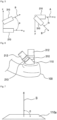
- FIG. 1 is a schematic view of a typical human ear illustrating the contact position of an electrode in a vagus nerve stimulator.
- the inventors of the present disclosure have developed a neuromodulation technique using the vagus nerve, unlike a transcranial magnetic stimulation method or a transcranial electrical stimulation method, in developing a neuromodulation technique for brain function activation.
- it is a technology that activates the limbic system and the cerebral cortex through multiple central nerve nuclei by stimulating the afferent sensory nerves non-invasively by the use of auricular vagus nerve stimulation.
- the cerebral cortex is stimulated from the outside, but in the case of the vagus nerve stimulation according to the present disclosure, it is a technology that can effectively stimulate the brainstem and the deep cerebral structures by stimulating the deep structures of the brain through the vagus nerve, which is the 10th cranial nerve.
- the locations where the vagus nerve passes are the external acoustic meatus and the cymba concha.
- the helicis crus which is a cartilage structure leading from the helix, is located horizontally, and separates the cavum concha, which is the entrance to the external acoustic meatus, and the cymba concha.
- an external acoustic meatus insertion-type structure has been developed in earphones and the like, and thus it is easy to construct an electrode making contact with the external acoustic meatus.
- the cymba concha which is a concave portion lying above the helicis crus, it is not easy to construct an electrode making contact with the cymba concha.
- an objective of the present disclosure is to provide a vagus nerve stimulator capable of closely attaching a first electrode and a second electrode to the ear simultaneously by specifying the positional relationship between the first electrode making contact with the external acoustic meatus and the second electrode making contact with the cymba concha.
- FIG. 2 is a perspective view illustrating the configuration of a vagus nerve stimulator according to an embodiment of the present disclosure.
- the vagus nerve stimulator includes a body part 100, a first electrode 200, a second electrode 300, and a connection part 400.
- the body part 100 corresponds to a body that is located on a side of a wearer's ear and is for forming the first electrode 200 and the second electrode 300 for transmitting electrical stimulation to the vagus nerve of the wearer.
- one body part 100 may be provided to be worn on one ear, or two body parts 100 may be provided to be worn on both ears.
- two body parts 100 are provided, and the first electrode 200 and the second electrode 300 are formed on each of the body parts 100.
- the first electrode 200 is an electrode that is inserted into and makes contact with the external acoustic meatus of the wearer's ear through the cavum concha of the wearer's ear. Since it is inserted into and makes contact with the external acoustic meatus leading from the outside to the inside of the ear, the first electrode 200 is formed to protrude from the body part 100.
- the first electrode 200 making contact with the external acoustic meatus is made of a conductive polymer having flexibility and elastic restoring force, it may be appropriately deformed according to the size of the external acoustic meatus that is anatomically different from person to person while conducting electricity, and may exert an increased contact force against the external acoustic meatus.
- the electrode may be restored to its original shape and size after being removed from the external acoustic meatus, and any problem due to deformation does not occur during repeated use.
- a configuration for sealing and close contact by using a polymer in earphones and the like may be applied.
- the first electrode 200 to which the conductive polymer is applied may be manufactured in a detachable shape so that only the electrode is replaced, and may be manufactured in various sizes to be used interchangeably by wearers, and only the electrode may be replaced when the electrode is damaged.
- sound or sound waves may be transmitted through the first electrode 200 inserted into the external acoustic meatus.
- music or sound for stabilizing purposes in a treatment process and sound waves for treatment may be transmitted.
- a sound unit for generating sound is provided in the body part 100, and a passage through which sound moves is formed in a space leading from the body part 100 to the first electrode 200 and in the first electrode 200.
- the activity of the cerebral cortex may be controlled through sound stimulation generated from the sound unit, and this effect can promote changes by influencing neural synapses related to degenerative brain diseases on the basis of neural plasticity.
- Non-invasive vagus nerve stimulation stimulates the cerebral cortex through the nucleus tractus solitarius, the locus coeruleus, and the nucleus basalis, thereby improving neural plasticity of the brain.
- it is possible to promote the formation of synapses, leading to improved learning ability.
- Changes in cerebral synapses caused by sound stimulation can improve the therapeutic efficacy in synergy with the improvement of neural plasticity by non-invasive vagus nerve stimulation according to the present disclosure.
- the second electrode 300 is an electrode that makes contact with the cymba concha of the wearer's ear.
- the vagus nerve stimulator according to the present disclosure is characterized by having the electrodes that transmit electrical stimulation by respectively making contact with the external acoustic meatus and the cymba concha.
- the second electrode 300 transmits electrical stimulation by making contact with the cymba concha.
- the second electrode 300 is formed to protrude from the body part 100.
- the second electrode 300 making contact with the cymba concha is made of a conductive polymer having flexibility and elastic restoring force, it may be appropriately deformed according to the structure and size of the cymba concha that is anatomically different from person to person while conducting electricity, and may exert an increased contact force against the cymba concha.
- almost the same effect as the case where the first electrode 200 is made of the conductive polymer can be obtained, and thus a detailed description thereof will be omitted.
- the first electrode 200 inserted into and making contact with the external acoustic meatus and the second electrode 300 making contact with the cymba concha which is a concave portion lying above the helicis crus, both protrude from the body part 100.
- the protruding structure and direction of the first electrode 200 and the second electrode 300 are not appropriate, they may interfere with each other and thus may fail to make close contact with the external acoustic meatus and the cymba concha. Accordingly, the present disclosure specifies the protruding structure and direction of the first electrode 200 and the second electrode 300, which will be described in more detail later.
- connection part 400 is a configuration that connects the two body parts 100 to each other. It is preferable that the connection part 400 is configured to not only connect the two body parts 100 to each other, but also exert elasticity to apply a force to the body parts 100 to make close contact with the wearer's ears.
- connection part 400 The force of causing the body parts 100 to make close contact with the ears by the connection part 400 enables the vagus nerve stimulator according to the present embodiment to be firmly attached to the wearer, and causes the first electrode 200 and the second electrode 300 formed on the body part 100 to make close contact with the wearer's skin, thereby making it easy for electrical stimulation to be transmitted to the vagus nerve in the ear through the electrodes.
- FIG. 3 is a partially enlarged view illustrating the configuration of the vagus nerve stimulator according to the embodiment of the present disclosure.
- FIG. 3 illustrates an enlarged view of a body part worn on the left ear among the two body parts 100.
- both the first electrode 200 and the second electrode 300 have to be formed to protrude from a forming surface 110 formed on each of the body parts 100 and located in a direction toward the wearer's head.
- the present disclosure adopts a structure in which the first electrode 200 made of the conductive polymer is attached to an end of a first electrode fixing part 210 protruding from the body part 100 and the second electrode 300 made of the conductive polymer is attached to an end of a second electrode fixing part 310 protruding from the body part 100.
- the protruding directions of the first electrode fixing part 210 and the second electrode fixing part 310 due to the positional relationship between the external acoustic meatus and the cymba concha.
- the protruding directions thereof have to be precisely defined so that the first electrode 200 and the second electrode 300 can make close contact with the external acoustic meatus and the cymba concha, respectively.
- the first electrode 200 inserted into and making contact with the external acoustic meatus has a forward protruding direction.
- the protruding direction and angle of the first electrode fixing part 210 to be inserted into the external acoustic meatus those proposed in the technical field of earphones and the like may be employed.
- the second electrode 300 that has to make contact with the cymba concha is not a configuration that is generally employed and has to be disposed obliquely upward with respect to the first electrode 200. For this reason, there is a problem in that the second electrode 300 may fail to make close contact with the cymba concha when it is designed incorrectly. Meanwhile, conventionally, in earphone-related technology, a structure that is rest on the cymba concha was employed for the purpose of holding earphones against ears, but this technique cannot be applied to the second electrode 300 and the second electrode fixing part 310 that transmit electrical stimulation.
- the inventors of the present disclosure have developed a vagus nerve stimulator in which the protruding direction of the second electrode fixing part 310 is optimized on the basis of the protruding direction of the first electrode fixing part 210 to which existing techniques are applicable.
- FIGS. 4 to 5 are schematic views illustrating the angular relationship between electrodes in the vagus nerve stimulator according to the embodiment of the present disclosure.
- the first electrode fixing part 210 is disposed so that the protruding direction thereof coincides with the x-axis
- the second electrode fixing part 310 is disposed so that the starting point thereof is on the z-axis. Then, the angle between a vector A with respect to the protruding direction of the first electrode fixing part 210 and a vector B with respect to the protruding direction of the second electrode fixing part 310 is specified with respect to the xy plane and the xz plane.
- An angle a between the vector A with respect to the protruding direction of the first electrode fixing part 210 and the vector B with respect to the protruding direction of the second electrode fixing part 310 on the xz plane is in the range of 10° to 20°. This is an angle slightly upward when the protruding direction of the first electrode fixing part 210 is a horizontal direction. In this angular range, the second electrode 300 can make close contact with the cymba concha, which lies above the helicis crus, without being interfered with by the helicis crus. More preferably, the angle a between the vector A with respect to the protruding direction of the first electrode fixing part 210 and the vector B with respect to the protruding direction of the second electrode fixing part 310 on the xz plane is 14.8 ⁇ 2°.
- An angle b between the vector A with respect to the protruding direction of the first electrode fixing part 210 and the vector B with respect to the protruding direction of the second electrode fixing part 310 on the xy plane is in the range of 35° to 45°.
- the second electrode fixing part 310 since the external acoustic meatus is disposed obliquely to the front of the face, the second electrode fixing part 310 has to be disposed so that the protruding direction thereof is oriented to the back of the face compared to the protruding direction of the first electrode fixing part 210.
- the direction in which the first electrode 200 is inserted into and makes contact with the external acoustic meatus and the direction in which the second electrode 300 makes contact with the cymba concha do not interfere with each other.
- the angle b between the vector A with respect to the protruding direction of the first electrode fixing part 210 and the vector B with respect to the protruding direction of the second electrode fixing part 310 on the xy plane is 39.7 ⁇ 2°.
- the electrodes are designed by specifying the angle between the vector A with respect to the protruding direction of the first electrode fixing part 210 and the vector B with respect to the protruding direction of the second electrode fixing part 310, it is possible to obtain the effect that the first electrode 200 is inserted into and makes close contact with the external acoustic meatus while the second electrode 200 makes close contact with the cymba concha.
- a problem occurs in that either one of the first electrode or the second electrode fails to make close contact with the ear or is difficult to wear.
- the first electrode fixing part 210 and the second electrode fixing part 310 have to be formed to protrude from the body part 100.
- the protruding length of the first electrode fixing part 210 from the body part 100 has to be equal to or larger than 6 mm
- the protruding length of the second electrode fixing part 310 from the body part 100 has to be equal to or larger than 5 mm.
- the distance from the body part 100 to an end of the first electrode 200 may be larger than the protruding length of the first electrode fixing part 210, and the size of the first electrode 200 made of the conductive polymer has to be taken into consideration in the final design process.
- the distance from the body part 100 to an end of the second electrode 300 may be larger than the protruding length of the second electrode fixing part 310, and the size of the second electrode 300 made of the conductive polymer has to be taken into consideration in the final design process.
- the first electrode fixing part 210 protrudes at a position spaced apart from the position where the second electrode fixing part 310 protrudes.
- the interval between the position where the first electrode fixing part 210 protrudes and the position where the second electrode fixing part 310 protrudes is 14.512 mm. This is a measurement of the closest distance between the first electrode fixing part 210 and the second electrode fixing part 310, and may be appropriately adjusted depending on the width of the first electrode fixing part 210 and the second electrode fixing part 310.
- FIGS. 6 to 7 are views illustrating the angular relationship between the second electrode and the body part in the vagus nerve stimulator according to the embodiment of the present disclosure.
- FIG. 6 illustrates a state in which the conductive polymer electrodes are removed from the first electrode fixing part 210 and the second electrode fixing part 310.
- Conductive portions 212 and 312 formed by exposing a conductive material are provided at respective portions of the first and second electrode fixing parts being in contact with the electrodes so that electricity passes through the electrodes attached to the respective ends thereof.
- the vagus nerve stimulator according to the present disclosure is configure such that the first electrode 200 and the second electrode 300 are formed to protrude from the forming surface 110 of each of the body parts 100, and the opposite body parts 100 make close contact with the wearer's face (ears) by the elasticity of the connection part 400. In this case, a force is applied in a direction in which the forming surface 110 of the body part 100 makes close contact with the wearer's ears.
- the force caused by the elasticity of the connection part 400 may be applied in a direction in which the first electrode 200 and the second electrode 300 make close contact with the external acoustic meatus and the cymba concha.
- a reference plane 110a which is a plane for setting an angle between the forming surface 110 and the first electrode fixing part 210 and the second electrode fixing part 310, is defined in the design process.
- the reference plane 110a is a plane corresponding to the forming surface 110 of the body part 100.
- it is preferable that a force is applied by the elasticity of the connection part 400 in a direction in which the reference plane 110a is parallel to the side of the wearer's face and makes close contact with the wearer's face (ear).
- a force may be applied in the protruding direction of the second electrode fixing part 310.
- the angle between the vector B with respect to the protruding direction of the second electrode fixing part 310 and the reference plane 110a is designed to be in the range of 80° to 90°, it is possible to obtain the effect that the force caused by the elasticity of the connection part 400 is applied in a direction in which the second electrode 300 makes close contact with the cymba concha, thereby enabling close contact between the second electrode 300 and the cymba concha.
Landscapes
- Health & Medical Sciences (AREA)
- Life Sciences & Earth Sciences (AREA)
- Engineering & Computer Science (AREA)
- Veterinary Medicine (AREA)
- Public Health (AREA)
- General Health & Medical Sciences (AREA)
- Animal Behavior & Ethology (AREA)
- Biomedical Technology (AREA)
- Nuclear Medicine, Radiotherapy & Molecular Imaging (AREA)
- Radiology & Medical Imaging (AREA)
- Heart & Thoracic Surgery (AREA)
- Psychology (AREA)
- Anesthesiology (AREA)
- Otolaryngology (AREA)
- Acoustics & Sound (AREA)
- Physics & Mathematics (AREA)
- Neurology (AREA)
- Biophysics (AREA)
- Pain & Pain Management (AREA)
- Hospice & Palliative Care (AREA)
- Developmental Disabilities (AREA)
- Psychiatry (AREA)
- Social Psychology (AREA)
- Child & Adolescent Psychology (AREA)
- Hematology (AREA)
- Neurosurgery (AREA)
- Orthopedic Medicine & Surgery (AREA)
- Cardiology (AREA)
- Signal Processing (AREA)
- Electrotherapy Devices (AREA)
Abstract
Description
- The present disclosure relates generally to a device for vagus nerve stimulation. More particularly, the present disclosure relates to a vagus nerve stimulator that is developed so that an electrode for applying electrical stimulation to the vagus nerve located in the ear can easily make close contact with a desired position.
- The vagus nerve is one of the cranial nerves and is also called the 10th cranial nerve. The vagus nerve runs from the brain through the face and thorax to the abdomen. It is a mixed nerve that contains parasympathetic fibers and is involved in the regulation of parasympathetic nerves acting on the heart, lungs, and digestive tract. It has the longest and most complex of the 12 pairs of cranial nerves, and contains both sensory and motor nerve fibers.
- It is known that a vagus nerve stimulator for the treatment of epilepsy and depression has been approved by the US Food and Drug Administration (FDA), and it targets the cervical branch of the vagus nerve located in the neck. However, this electrical stimulation of the cervical branch of the vagus nerve is a surgical procedure involving making an incision in the skin to expose the cervical branch of the vagus nerve, winding a coil, which is an electrical body, around the cervical branch, and grafting a microchip therein. Thus, it cannot be used in the field of self-treatment by the general public.
- Meanwhile, the human ear is considered as a body part where electrical stimulation can be applied to the vagus nerve by externally applying electrical stimulation to the vagus nerve because it is the main path through which the vagus nerve passes and is the region where the vagus nerve is located close to the skin surface. In oriental medicine, a method of treating diseases by ear acupuncture has been used. Since the ear is where the auricular branch of the vagus nerve is located, it can be said that the principle of ear acupuncture therapy is based on stimulation of the vagus nerve. However, the use of acupuncture is problematic in that it is not applicable to the general public.
- Accordingly, a technique for applying electrical stimulation by contacting a wearer's ear with an electrode has been developed. However, there is a drawback in that the electrode is manufactured in a shape that is difficult to wear and has a low wearing comfort.
- Accordingly, the present disclosure has been made keeping in mind the above problems occurring in the related art, and an objective of the present disclosure is to provide a vagus nerve stimulator in which an electrode is disposed to facilitate stimulation of the vagus nerve located in the ear.
- In order to achieve the above objective, according to one aspect of the present disclosure, there is provided a vagus nerve stimulator having at least two electrodes that are configured to be worn on at least one of the left and right ears and are configured to generate electrical stimulation on the vagus nerve in the auricle, the vagus nerve stimulator including: a body part configured to be located on a side of a wearer's ear; a first electrode configured to be inserted into and make contact with the external acoustic meatus of the wearer's ear; a second electrode configured to make contact with the cymba concha of the wearer's ear; a first electrode fixing part protruding from the body part and having a first electrode at an end thereof; and a second electrode fixing part protruding from the body part and having a second electrode at an end thereof. Here, when a protruding direction of the first electrode fixing part coincides with the x-axis of a three-dimensional coordinate system, an angle between a protruding direction of the second electrode fixing part and the protruding direction of the first electrode fixing part may be in a range of 10° to 20° on the xz plane and in a range of 35° to 45° on the xy plane.
- The angle between the protruding direction of the second electrode fixing part and the protruding direction of the first electrode fixing part may be 14.812° on the xz plane and 39.7±2° on the xy plane.
- An interval between a position where the first electrode fixing part protrudes from the body part and a position where the second electrode fixing part protrudes from the body part may be 14.5±2 mm.
- A protruding length of the first electrode fixing part from the body part may be equal to or larger than 6 mm.
- A protruding length of the second electrode fixing part from the body part may be equal to or larger than 5 mm.
- The first electrode may be made of a flexible conductive polymer.
- The second electrode may be made of a flexible conductive polymer.
- The body part may include a forming surface from which the first electrode fixing part and the second electrode fixing part protrude, and the second electrode fixing part may be disposed at an angle of 80° to 90° with respect to a reference plane of the forming surface.
- Furthermore, the body part may be configured as a pair of body parts respectively corresponding to the left and right ears. Here, the pair of body parts may be configured such that the respective second electrode fixing parts and the respective first electrode fixing parts protrude in a mirror-symmetrical shape with respect to the wearer's head.
- The vagus nerve stimulator may further include a connection part connecting the pair of body parts to each other. Here, the connection part may apply a force in a direction in which the body parts make close contact with the wearer's head.
- Each of the body parts may include a forming surface from which the first electrode fixing part and the second electrode fixing part protrude, and the second electrode fixing part may be disposed at an angle of 80° to 90° with respect to a reference plane of the forming surface.
- According to the present disclosure configured as described above, by specifying the formation position of a second electrode with respect to an electrode inserted into the external acoustic meatus of the ear as a position where contact of the second electrode with the cymba concha of the ear is facilitated, it is possible to provide a vagus nerve stimulator having improved contact characteristics with the cymba concha.
- In addition, by adjusting the angle of electrodes and a body part where the electrodes are formed, the electrodes are configured to make contact with the cymba concha as the body part makes close contact with the ear. Thus, it is possible to achieve close contact between the electrodes and the cymba concha by a configuration for fixing the body part.
-
-
FIG. 1 is a schematic view of a typical human ear illustrating the contact position of an electrode in a vagus nerve stimulator. -
FIG. 2 is a perspective view illustrating the configuration of a vagus nerve stimulator according to an embodiment of the present disclosure. -
FIG. 3 is a partially enlarged view illustrating the configuration of the vagus nerve stimulator according to the embodiment of the present disclosure. -
FIGS. 4 to 5 are schematic views illustrating the angular relationship between electrodes in the vagus nerve stimulator according to the embodiment of the present disclosure. -
FIGS. 6 to 7 are views illustrating the angular relationship between a second electrode and a body part in the vagus nerve stimulator according to the embodiment of the present disclosure. -
- 100:
- body part
- 110:
- forming surface
- 110a:
- reference plane
- 200:
- first electrode
- 210:
- first electrode fixing part
- 212:
- conductive portion
- 300:
- second electrode
- 310:
- second electrode fixing part
- 312:
- conductive portion
- 400:
- connection part
- Reference will now be made in detail to an exemplary embodiment of the present disclosure, examples of which are illustrated in the accompanying drawings.
- Various changes to the following embodiment are possible and the scope of the present disclosure is not limited to the following embodiment. In the drawings, the shape and size of elements may be exaggeratedly drawn to provide an easily understood description of the structure of the present disclosure. Wherever possible, the same reference numerals will be used throughout the drawings and the description to refer to the same or like elements or parts.
- Also, when an element is referred to as being "connected" to another element, it can be "directly connected" to the other element or can be "electrically connected" to the other element with one or more intervening elements therebetween. It will be understood that terms such as "comprise", "include", and "have", when used herein, specify the presence of stated features, integers, steps, operations, elements, components, or combinations thereof, but do not preclude the presence or addition of one or more other features, integers, steps, operations, elements, components, or combinations thereof.
- Further, the terms "first", "second", etc. may be used herein to describe various elements, but these elements should not be limited by these terms. These terms are only used to distinguish one element from another element. For instance, a first element discussed below could be termed a second element, and the second element could also be termed the first element.
-
FIG. 1 is a schematic view of a typical human ear illustrating the contact position of an electrode in a vagus nerve stimulator. - The inventors of the present disclosure have developed a neuromodulation technique using the vagus nerve, unlike a transcranial magnetic stimulation method or a transcranial electrical stimulation method, in developing a neuromodulation technique for brain function activation. In particular, it is a technology that activates the limbic system and the cerebral cortex through multiple central nerve nuclei by stimulating the afferent sensory nerves non-invasively by the use of auricular vagus nerve stimulation.
- In the case of transcranial magnetic stimulation or transcranial electrical stimulation, the cerebral cortex is stimulated from the outside, but in the case of the vagus nerve stimulation according to the present disclosure, it is a technology that can effectively stimulate the brainstem and the deep cerebral structures by stimulating the deep structures of the brain through the vagus nerve, which is the 10th cranial nerve.
- In the human ear, the locations where the vagus nerve passes are the external acoustic meatus and the cymba concha. Here, the helicis crus, which is a cartilage structure leading from the helix, is located horizontally, and separates the cavum concha, which is the entrance to the external acoustic meatus, and the cymba concha.
- In the case of the external acoustic meatus, an external acoustic meatus insertion-type structure has been developed in earphones and the like, and thus it is easy to construct an electrode making contact with the external acoustic meatus. However, due to the positional characteristics and morphological characteristics of the cymba concha, which is a concave portion lying above the helicis crus, it is not easy to construct an electrode making contact with the cymba concha.
- In particular, when an electrode making contact with the external acoustic meatus and an electrode making contact with the cymba concha are provided simultaneously, there is a drawback in that the electrode making contact with the cymba concha fails to make close contact with the skin and thus fails to accurately transmit electrical stimulation. In an effort to solve this problem, the inventors of the present disclosure have researched a vagus nerve stimulator in a form that allows the position or height of an electrode making contact with the cymba concha to be adjusted so that an electrode making contact with the external acoustic meatus and the electrode making contact with the cymba concha can make close contact with the ear simultaneously, and have filed an application for patent. However, in the process including a configuration for adjusting the position of the electrode, the structure of the stimulator became complicated, resulting in an increase in manufacturing costs, and a problem of frequent failures during use.
- In order to solve such problems, an objective of the present disclosure is to provide a vagus nerve stimulator capable of closely attaching a first electrode and a second electrode to the ear simultaneously by specifying the positional relationship between the first electrode making contact with the external acoustic meatus and the second electrode making contact with the cymba concha.
-
FIG. 2 is a perspective view illustrating the configuration of a vagus nerve stimulator according to an embodiment of the present disclosure. - The vagus nerve stimulator according to the present embodiment includes a
body part 100, afirst electrode 200, asecond electrode 300, and aconnection part 400. - The
body part 100 corresponds to a body that is located on a side of a wearer's ear and is for forming thefirst electrode 200 and thesecond electrode 300 for transmitting electrical stimulation to the vagus nerve of the wearer. In this case, onebody part 100 may be provided to be worn on one ear, or twobody parts 100 may be provided to be worn on both ears. In the present embodiment, twobody parts 100 are provided, and thefirst electrode 200 and thesecond electrode 300 are formed on each of thebody parts 100. - The
first electrode 200 is an electrode that is inserted into and makes contact with the external acoustic meatus of the wearer's ear through the cavum concha of the wearer's ear. Since it is inserted into and makes contact with the external acoustic meatus leading from the outside to the inside of the ear, thefirst electrode 200 is formed to protrude from thebody part 100. - In this case, when the
first electrode 200 making contact with the external acoustic meatus is made of a conductive polymer having flexibility and elastic restoring force, it may be appropriately deformed according to the size of the external acoustic meatus that is anatomically different from person to person while conducting electricity, and may exert an increased contact force against the external acoustic meatus. In addition, the electrode may be restored to its original shape and size after being removed from the external acoustic meatus, and any problem due to deformation does not occur during repeated use. As for the structure and shape of thefirst electrode 200 to which the conductive polymer is applied, a configuration for sealing and close contact by using a polymer in earphones and the like may be applied. In addition, thefirst electrode 200 to which the conductive polymer is applied may be manufactured in a detachable shape so that only the electrode is replaced, and may be manufactured in various sizes to be used interchangeably by wearers, and only the electrode may be replaced when the electrode is damaged. - Meanwhile, sound or sound waves may be transmitted through the
first electrode 200 inserted into the external acoustic meatus. For example, music or sound for stabilizing purposes in a treatment process and sound waves for treatment may be transmitted. To this end, a sound unit for generating sound is provided in thebody part 100, and a passage through which sound moves is formed in a space leading from thebody part 100 to thefirst electrode 200 and in thefirst electrode 200. The activity of the cerebral cortex may be controlled through sound stimulation generated from the sound unit, and this effect can promote changes by influencing neural synapses related to degenerative brain diseases on the basis of neural plasticity. Non-invasive vagus nerve stimulation according to the present disclosure stimulates the cerebral cortex through the nucleus tractus solitarius, the locus coeruleus, and the nucleus basalis, thereby improving neural plasticity of the brain. Thus, it is possible to promote the formation of synapses, leading to improved learning ability. Changes in cerebral synapses caused by sound stimulation can improve the therapeutic efficacy in synergy with the improvement of neural plasticity by non-invasive vagus nerve stimulation according to the present disclosure. - The
second electrode 300 is an electrode that makes contact with the cymba concha of the wearer's ear. The vagus nerve stimulator according to the present disclosure is characterized by having the electrodes that transmit electrical stimulation by respectively making contact with the external acoustic meatus and the cymba concha. Thesecond electrode 300 transmits electrical stimulation by making contact with the cymba concha. Here, due to the concave shape of the cymba concha lying above the helicis crus, thesecond electrode 300 is formed to protrude from thebody part 100. - In this case, when the
second electrode 300 making contact with the cymba concha is made of a conductive polymer having flexibility and elastic restoring force, it may be appropriately deformed according to the structure and size of the cymba concha that is anatomically different from person to person while conducting electricity, and may exert an increased contact force against the cymba concha. In addition, almost the same effect as the case where thefirst electrode 200 is made of the conductive polymer can be obtained, and thus a detailed description thereof will be omitted. - Meanwhile, the
first electrode 200 inserted into and making contact with the external acoustic meatus and thesecond electrode 300 making contact with the cymba concha, which is a concave portion lying above the helicis crus, both protrude from thebody part 100. In this case, when the protruding structure and direction of thefirst electrode 200 and thesecond electrode 300 are not appropriate, they may interfere with each other and thus may fail to make close contact with the external acoustic meatus and the cymba concha. Accordingly, the present disclosure specifies the protruding structure and direction of thefirst electrode 200 and thesecond electrode 300, which will be described in more detail later. - The
connection part 400 is a configuration that connects the twobody parts 100 to each other. It is preferable that theconnection part 400 is configured to not only connect the twobody parts 100 to each other, but also exert elasticity to apply a force to thebody parts 100 to make close contact with the wearer's ears. - The force of causing the
body parts 100 to make close contact with the ears by theconnection part 400 enables the vagus nerve stimulator according to the present embodiment to be firmly attached to the wearer, and causes thefirst electrode 200 and thesecond electrode 300 formed on thebody part 100 to make close contact with the wearer's skin, thereby making it easy for electrical stimulation to be transmitted to the vagus nerve in the ear through the electrodes. -
FIG. 3 is a partially enlarged view illustrating the configuration of the vagus nerve stimulator according to the embodiment of the present disclosure. -
FIG. 3 illustrates an enlarged view of a body part worn on the left ear among the twobody parts 100. As described above, since thefirst electrode 200 has to be inserted into the external acoustic meatus and thesecond electrode 300 has to make contact with the cymba concha, both thefirst electrode 200 and thesecond electrode 300 have to be formed to protrude from a formingsurface 110 formed on each of thebody parts 100 and located in a direction toward the wearer's head. Thus, the present disclosure adopts a structure in which thefirst electrode 200 made of the conductive polymer is attached to an end of a firstelectrode fixing part 210 protruding from thebody part 100 and thesecond electrode 300 made of the conductive polymer is attached to an end of a secondelectrode fixing part 310 protruding from thebody part 100. In this case, there is a difference in the protruding directions of the firstelectrode fixing part 210 and the secondelectrode fixing part 310 due to the positional relationship between the external acoustic meatus and the cymba concha. Thus, the protruding directions thereof have to be precisely defined so that thefirst electrode 200 and thesecond electrode 300 can make close contact with the external acoustic meatus and the cymba concha, respectively. - Since it is widely known that the external acoustic meatus of the human ear lies at an oblique angle to the front, it is preferable that the
first electrode 200 inserted into and making contact with the external acoustic meatus has a forward protruding direction. Here, as the protruding direction and angle of the firstelectrode fixing part 210 to be inserted into the external acoustic meatus, those proposed in the technical field of earphones and the like may be employed. - On the other hand, the
second electrode 300 that has to make contact with the cymba concha is not a configuration that is generally employed and has to be disposed obliquely upward with respect to thefirst electrode 200. For this reason, there is a problem in that thesecond electrode 300 may fail to make close contact with the cymba concha when it is designed incorrectly. Meanwhile, conventionally, in earphone-related technology, a structure that is rest on the cymba concha was employed for the purpose of holding earphones against ears, but this technique cannot be applied to thesecond electrode 300 and the secondelectrode fixing part 310 that transmit electrical stimulation. - As a solution for the above problem, the inventors of the present disclosure have developed a vagus nerve stimulator in which the protruding direction of the second
electrode fixing part 310 is optimized on the basis of the protruding direction of the firstelectrode fixing part 210 to which existing techniques are applicable. -
FIGS. 4 to 5 are schematic views illustrating the angular relationship between electrodes in the vagus nerve stimulator according to the embodiment of the present disclosure. - First, as illustrated in
FIG. 4 , in a three-dimensional coordinate system, the firstelectrode fixing part 210 is disposed so that the protruding direction thereof coincides with the x-axis, and the secondelectrode fixing part 310 is disposed so that the starting point thereof is on the z-axis. Then, the angle between a vector A with respect to the protruding direction of the firstelectrode fixing part 210 and a vector B with respect to the protruding direction of the secondelectrode fixing part 310 is specified with respect to the xy plane and the xz plane. - An angle a between the vector A with respect to the protruding direction of the first
electrode fixing part 210 and the vector B with respect to the protruding direction of the secondelectrode fixing part 310 on the xz plane is in the range of 10° to 20°. This is an angle slightly upward when the protruding direction of the firstelectrode fixing part 210 is a horizontal direction. In this angular range, thesecond electrode 300 can make close contact with the cymba concha, which lies above the helicis crus, without being interfered with by the helicis crus. More preferably, the angle a between the vector A with respect to the protruding direction of the firstelectrode fixing part 210 and the vector B with respect to the protruding direction of the secondelectrode fixing part 310 on the xz plane is 14.8±2°. - An angle b between the vector A with respect to the protruding direction of the first
electrode fixing part 210 and the vector B with respect to the protruding direction of the secondelectrode fixing part 310 on the xy plane is in the range of 35° to 45°. As described above, since the external acoustic meatus is disposed obliquely to the front of the face, the secondelectrode fixing part 310 has to be disposed so that the protruding direction thereof is oriented to the back of the face compared to the protruding direction of the firstelectrode fixing part 210. In this angular range, the direction in which thefirst electrode 200 is inserted into and makes contact with the external acoustic meatus and the direction in which thesecond electrode 300 makes contact with the cymba concha do not interfere with each other. More preferably, the angle b between the vector A with respect to the protruding direction of the firstelectrode fixing part 210 and the vector B with respect to the protruding direction of the secondelectrode fixing part 310 on the xy plane is 39.7±2°. - As such, when the electrodes are designed by specifying the angle between the vector A with respect to the protruding direction of the first
electrode fixing part 210 and the vector B with respect to the protruding direction of the secondelectrode fixing part 310, it is possible to obtain the effect that thefirst electrode 200 is inserted into and makes close contact with the external acoustic meatus while thesecond electrode 200 makes close contact with the cymba concha. When being out of the above ranges, a problem occurs in that either one of the first electrode or the second electrode fails to make close contact with the ear or is difficult to wear. - In this case, as described above, due to the structural characteristics of the external acoustic meatus and the cymba concha, the first
electrode fixing part 210 and the secondelectrode fixing part 310 have to be formed to protrude from thebody part 100. The protruding length of the firstelectrode fixing part 210 from thebody part 100 has to be equal to or larger than 6 mm, and the protruding length of the secondelectrode fixing part 310 from thebody part 100 has to be equal to or larger than 5 mm. When the protruding length is shorter than these ranges, it becomes difficult for the electrodes to make close contact with the external acoustic meatus and the cymba concha. Meanwhile, due to thefirst electrode 200 made of the conductive polymer and attached to the end of the firstelectrode fixing part 210, the distance from thebody part 100 to an end of thefirst electrode 200 may be larger than the protruding length of the firstelectrode fixing part 210, and the size of thefirst electrode 200 made of the conductive polymer has to be taken into consideration in the final design process. Similarly, due to thesecond electrode 300 made of the conductive polymer and attached to the end of the secondelectrode fixing part 310, the distance from thebody part 100 to an end of thesecond electrode 300 may be larger than the protruding length of the secondelectrode fixing part 310, and the size of thesecond electrode 300 made of the conductive polymer has to be taken into consideration in the final design process. When being out of the above ranges, a problem occurs in that either one of the first electrode or the second electrode fails to make close contact with the ear or is difficult to wear. - Furthermore, on the
body part 100, the firstelectrode fixing part 210 protrudes at a position spaced apart from the position where the secondelectrode fixing part 310 protrudes. Preferably, the interval between the position where the firstelectrode fixing part 210 protrudes and the position where the secondelectrode fixing part 310 protrudes is 14.512 mm. This is a measurement of the closest distance between the firstelectrode fixing part 210 and the secondelectrode fixing part 310, and may be appropriately adjusted depending on the width of the firstelectrode fixing part 210 and the secondelectrode fixing part 310. -
FIGS. 6 to 7 are views illustrating the angular relationship between the second electrode and the body part in the vagus nerve stimulator according to the embodiment of the present disclosure. -
FIG. 6 illustrates a state in which the conductive polymer electrodes are removed from the firstelectrode fixing part 210 and the secondelectrode fixing part 310.Conductive portions - As described above, the vagus nerve stimulator according to the present disclosure is configure such that the
first electrode 200 and thesecond electrode 300 are formed to protrude from the formingsurface 110 of each of thebody parts 100, and theopposite body parts 100 make close contact with the wearer's face (ears) by the elasticity of theconnection part 400. In this case, a force is applied in a direction in which the formingsurface 110 of thebody part 100 makes close contact with the wearer's ears. When the protruding directions of the firstelectrode fixing part 210 and the secondelectrode fixing part 310 are appropriately configured, the force caused by the elasticity of theconnection part 400 may be applied in a direction in which thefirst electrode 200 and thesecond electrode 300 make close contact with the external acoustic meatus and the cymba concha. - Here, since the forming
surface 110 of thebody part 100 is not a perfect plane, areference plane 110a, which is a plane for setting an angle between the formingsurface 110 and the firstelectrode fixing part 210 and the secondelectrode fixing part 310, is defined in the design process. Thereference plane 110a is a plane corresponding to the formingsurface 110 of thebody part 100. In designing the simulator, it is preferable that a force is applied by the elasticity of theconnection part 400 in a direction in which thereference plane 110a is parallel to the side of the wearer's face and makes close contact with the wearer's face (ear). Thus, as the angle between the vector B with respect to the protruding direction of the secondelectrode fixing part 310 and thereference plane 110a is closer to vertical, a force may be applied in the protruding direction of the secondelectrode fixing part 310. In view of this, when the angle between the vector B with respect to the protruding direction of the secondelectrode fixing part 310 and thereference plane 110a is designed to be in the range of 80° to 90°, it is possible to obtain the effect that the force caused by the elasticity of theconnection part 400 is applied in a direction in which thesecond electrode 300 makes close contact with the cymba concha, thereby enabling close contact between thesecond electrode 300 and the cymba concha. - While the exemplary embodiment of the present disclosure has been described above, the embodiment is only an example of the present disclosure, and it will be understood by those skilled in the art that the present disclosure can be modified in various forms without departing from the technical spirit of the present disclosure. Therefore, the scope of the present disclosure should be determined on the basis of the descriptions in the appended claims, not any specific embodiment, and all equivalents thereof should belong to the scope of the present disclosure.
Claims (11)
- A vagus nerve stimulator having at least two electrodes that are configured to be worn on at least one of the left and right ears and are configured to generate electrical stimulation on the vagus nerve in the auricle, the vagus nerve stimulator comprising:a body part configured to be located on a side of a wearer's ear;a first electrode configured to be inserted into and make contact with the external acoustic meatus of the wearer's ear;a second electrode configured to make contact with the cymba concha of the wearer's ear;a first electrode fixing part protruding from the body part and having a first electrode at an end thereof; anda second electrode fixing part protruding from the body part and having a second electrode at an end thereof,wherein when a protruding direction of the first electrode fixing part coincides with the x-axis of a three-dimensional coordinate system, an angle between a protruding direction of the second electrode fixing part and the protruding direction of the first electrode fixing part is in a range of 10° to 20° on the xz plane and in a range of 35° to 45° on the xy plane.
- The vagus nerve stimulator of claim 1, wherein the angle between the protruding direction of the second electrode fixing part and the protruding direction of the first electrode fixing part is 14.8±2° on the xz plane and 39.7±2° on the xy plane.
- The vagus nerve stimulator of claim 1, wherein an interval between a position where the first electrode fixing part protrudes from the body part and a position where the second electrode fixing part protrudes from the body part is 14.512 mm.
- The vagus nerve stimulator of claim 1, wherein a protruding length of the first electrode fixing part from the body part is equal to or larger than 6 mm.
- The vagus nerve stimulator of claim 1, wherein a protruding length of the second electrode fixing part from the body part is equal to or larger than 5 mm.
- The vagus nerve stimulator of claim 1, wherein the first electrode is made of a flexible conductive polymer.
- The vagus nerve stimulator of claim 1, wherein the second electrode is made of a flexible conductive polymer.
- The vagus nerve stimulator of claim 1, wherein the body part comprises a forming surface from which the first electrode fixing part and the second electrode fixing part protrude, and
the second electrode fixing part is disposed at an angle of 80° to 90° with respect to a reference plane of the forming surface. - The vagus nerve stimulator of claim 1, wherein the body part is configured as a pair of body parts respectively corresponding to the left and right ears,
wherein the pair of body parts are configured such that the respective second electrode fixing parts and the respective first electrode fixing parts protrude in a mirror-symmetrical shape with respect to the wearer's head. - The vagus nerve stimulator of claim 9, further comprising a connection part connecting the pair of body parts to each other,
wherein the connection part applies a force in a direction in which the body parts make close contact with the wearer's head. - The vagus nerve stimulator of claim 10, wherein each of the body parts comprises a forming surface from which the first electrode fixing part and the second electrode fixing part protrude, and
the second electrode fixing part is disposed at an angle of 80° to 90° with respect to a reference plane of the forming surface.
Applications Claiming Priority (2)
| Application Number | Priority Date | Filing Date | Title |
|---|---|---|---|
| KR1020210138039A KR102649949B1 (en) | 2021-10-18 | 2021-10-18 | Stimulation apparatus for vagus nerve |
| PCT/KR2021/017969 WO2023068442A1 (en) | 2021-10-18 | 2021-12-01 | Vagus nerve stimulation device |
Publications (3)
| Publication Number | Publication Date |
|---|---|
| EP4194047A1 true EP4194047A1 (en) | 2023-06-14 |
| EP4194047A4 EP4194047A4 (en) | 2024-04-17 |
| EP4194047B1 EP4194047B1 (en) | 2025-10-29 |
Family
ID=86059234
Family Applications (1)
| Application Number | Title | Priority Date | Filing Date |
|---|---|---|---|
| EP21895914.6A Active EP4194047B1 (en) | 2021-10-18 | 2021-12-01 | Vagus nerve stimulation device |
Country Status (6)
| Country | Link |
|---|---|
| US (1) | US20240173543A1 (en) |
| EP (1) | EP4194047B1 (en) |
| JP (1) | JP7719554B2 (en) |
| KR (1) | KR102649949B1 (en) |
| CN (1) | CN116472087A (en) |
| WO (1) | WO2023068442A1 (en) |
Families Citing this family (2)
| Publication number | Priority date | Publication date | Assignee | Title |
|---|---|---|---|---|
| WO2025255535A1 (en) * | 2024-06-06 | 2025-12-11 | Aurenar, Inc. | Wearable devices with adjustment mechanisms |
| WO2026010350A1 (en) * | 2024-07-05 | 2026-01-08 | 주식회사 케이티앤지 | Electrical stimulation device and electrical stimulation method using same |
Family Cites Families (13)
| Publication number | Priority date | Publication date | Assignee | Title |
|---|---|---|---|---|
| KR100596540B1 (en) | 2004-11-03 | 2006-07-06 | 정종필 | Vagus Nerve Stimulator |
| DE202010014951U1 (en) * | 2010-05-28 | 2011-11-25 | Cerbomed Gmbh | electrode assembly |
| CA2981044A1 (en) * | 2015-03-27 | 2016-10-06 | Elwha Llc | Ear stimulation method and system |
| CN109069297A (en) * | 2015-11-23 | 2018-12-21 | 通用医疗公司 | System and method for the percutaneous vagal stimulation of auricle formula |
| CN206566348U (en) * | 2016-12-26 | 2017-10-20 | 江西心之乐医疗科技有限公司 | It is a kind of to be used to stimulate ear's electrode of nervus auricularis vagi |
| JP2020525252A (en) * | 2017-06-26 | 2020-08-27 | ヴォルソ コープ | Peripheral nerve stimulator for influencing sympathetic nerve and sympathetic nerve activity to obtain therapeutic effect |
| KR102152084B1 (en) | 2018-01-18 | 2020-09-04 | 고려대학교 산학협력단 | Nerve stimulation device |
| US10695568B1 (en) * | 2018-12-10 | 2020-06-30 | Spark Biomedical, Inc. | Device and method for the treatment of substance use disorders |
| KR102163194B1 (en) | 2019-08-23 | 2020-10-08 | (주)웰튠 | Bone Conduction Earphone with Assist Device for Improving Audibility |
| US11571563B2 (en) * | 2019-09-11 | 2023-02-07 | Bose Corporation | Electrically conductive ear tips |
| AU2020347872B2 (en) | 2019-09-20 | 2026-04-16 | Neurotone Australia Pty Ltd | Medical treatment device and method of operation thereof |
| KR102185269B1 (en) | 2020-03-20 | 2020-12-01 | 충남대학교산학협력단 | Apparatus, method, computer-readable storage medium and computer program for personalized tinnitus treatments |
| CN111603682B (en) * | 2020-06-28 | 2023-10-27 | 江苏鱼跃医疗设备股份有限公司 | Improved ear vagus nerve stimulator |
-
2021
- 2021-10-18 KR KR1020210138039A patent/KR102649949B1/en active Active
- 2021-12-01 WO PCT/KR2021/017969 patent/WO2023068442A1/en not_active Ceased
- 2021-12-01 JP JP2024547391A patent/JP7719554B2/en active Active
- 2021-12-01 US US17/789,954 patent/US20240173543A1/en active Pending
- 2021-12-01 EP EP21895914.6A patent/EP4194047B1/en active Active
- 2021-12-01 CN CN202180007280.7A patent/CN116472087A/en active Pending
Also Published As
| Publication number | Publication date |
|---|---|
| EP4194047A4 (en) | 2024-04-17 |
| EP4194047B1 (en) | 2025-10-29 |
| US20240173543A1 (en) | 2024-05-30 |
| JP7719554B2 (en) | 2025-08-06 |
| KR102649949B1 (en) | 2024-03-22 |
| KR20230054937A (en) | 2023-04-25 |
| CN116472087A (en) | 2023-07-21 |
| WO2023068442A1 (en) | 2023-04-27 |
| JP2024536934A (en) | 2024-10-08 |
Similar Documents
| Publication | Publication Date | Title |
|---|---|---|
| JP4961016B2 (en) | Device for applying a stimulus percutaneously or detecting a parameter percutaneously | |
| EP3154626B1 (en) | Transcutaneous electrostimulator | |
| JP2022009757A (en) | Device and method for non-invasive capacitive electric stimulation and use thereof for stimulating vagas nerve on neck of patient | |
| US12551700B2 (en) | Adjustable auricular nerve stimulation devices, and associated systems and methods | |
| JP2023075350A (en) | Auricular nerve field stimulation device | |
| MX2012004050A (en) | Devices, systems and methods for treatment of neuropsychiatric disorders. | |
| WO2024031086A1 (en) | Devices and methods for neural stimulation | |
| EP4194047B1 (en) | Vagus nerve stimulation device | |
| WO2017091705A1 (en) | System and method for ear-arranged transcutaneous vagus nerve stimulation | |
| CN106137710A (en) | For preventing the virtual reality control system of senile dementia | |
| JP2015231511A (en) | Electrotherapy apparatus | |
| US20250108223A1 (en) | Housing arrangements for magnet rotation | |
| US20250010071A1 (en) | Method for controlling complex stimulation and complex stimulation device | |
| CN211132719U (en) | Percutaneous cranium ear electric stimulation instrument | |
| CN112295103A (en) | Percutaneous cranium ear electric stimulation instrument | |
| CN119255837A (en) | Vestibular stimulation for movement disorders | |
| US20240374896A1 (en) | Method for controlling vagus nerve stimulation | |
| CN222018756U (en) | Electrotherapy earplugs and portable human acupoint massager | |
| US20250381392A1 (en) | Methods And Apparatuses For Inhibiting Movement Of Implanted Magnetic Devices | |
| US20250381420A1 (en) | Ultrasonic auricular vagus nerve stimulator with cannabinoid coupling | |
| US20250352815A1 (en) | Methods, systems, apparatuses, and devices for suppression of the chronic inflammatory response through vagal nerve simulation | |
| US20240066302A1 (en) | Adaptive neural interface | |
| TWI638670B (en) | Brain healthy device |
Legal Events
| Date | Code | Title | Description |
|---|---|---|---|
| STAA | Information on the status of an ep patent application or granted ep patent |
Free format text: STATUS: UNKNOWN |
|
| STAA | Information on the status of an ep patent application or granted ep patent |
Free format text: STATUS: THE INTERNATIONAL PUBLICATION HAS BEEN MADE |
|
| PUAI | Public reference made under article 153(3) epc to a published international application that has entered the european phase |
Free format text: ORIGINAL CODE: 0009012 |
|
| STAA | Information on the status of an ep patent application or granted ep patent |
Free format text: STATUS: REQUEST FOR EXAMINATION WAS MADE |
|
| 17P | Request for examination filed |
Effective date: 20220530 |
|
| AK | Designated contracting states |
Kind code of ref document: A1 Designated state(s): AL AT BE BG CH CY CZ DE DK EE ES FI FR GB GR HR HU IE IS IT LI LT LU LV MC MK MT NL NO PL PT RO RS SE SI SK SM TR |
|
| RAP1 | Party data changed (applicant data changed or rights of an application transferred) |
Owner name: KOREA UNIVERSITY RESEARCH AND BUSINESS FOUNDATION Owner name: NEURIVE CO., LTD. |
|
| RAP1 | Party data changed (applicant data changed or rights of an application transferred) |
Owner name: NEURIVE CO., LTD. |
|
| A4 | Supplementary search report drawn up and despatched |
Effective date: 20240315 |
|
| RIC1 | Information provided on ipc code assigned before grant |
Ipc: H04R 5/033 20060101ALN20240311BHEP Ipc: H04R 1/02 20060101ALI20240311BHEP Ipc: A61N 1/05 20060101ALI20240311BHEP Ipc: A61H 39/00 20060101ALI20240311BHEP Ipc: A61M 21/00 20060101ALI20240311BHEP Ipc: A61M 21/02 20060101ALI20240311BHEP Ipc: A61N 1/04 20060101ALI20240311BHEP Ipc: A61N 1/36 20060101AFI20240311BHEP |
|
| DAV | Request for validation of the european patent (deleted) | ||
| DAX | Request for extension of the european patent (deleted) | ||
| GRAP | Despatch of communication of intention to grant a patent |
Free format text: ORIGINAL CODE: EPIDOSNIGR1 |
|
| STAA | Information on the status of an ep patent application or granted ep patent |
Free format text: STATUS: GRANT OF PATENT IS INTENDED |
|
| RIC1 | Information provided on ipc code assigned before grant |
Ipc: H04R 5/033 20060101ALN20250507BHEP Ipc: H04R 1/02 20060101ALI20250507BHEP Ipc: A61N 1/05 20060101ALI20250507BHEP Ipc: A61H 39/00 20060101ALI20250507BHEP Ipc: A61M 21/00 20060101ALI20250507BHEP Ipc: A61M 21/02 20060101ALI20250507BHEP Ipc: A61N 1/04 20060101ALI20250507BHEP Ipc: A61N 1/36 20060101AFI20250507BHEP |
|
| INTG | Intention to grant announced |
Effective date: 20250519 |
|
| RIN1 | Information on inventor provided before grant (corrected) |
Inventor name: HONG, KI HWAN Inventor name: CHOI, HYUK Inventor name: JUNG, YONG HO Inventor name: KIM, GUK HAN Inventor name: SONG, JAE JUN |
|
| GRAS | Grant fee paid |
Free format text: ORIGINAL CODE: EPIDOSNIGR3 |
|
| GRAA | (expected) grant |
Free format text: ORIGINAL CODE: 0009210 |
|
| STAA | Information on the status of an ep patent application or granted ep patent |
Free format text: STATUS: THE PATENT HAS BEEN GRANTED |
|
| AK | Designated contracting states |
Kind code of ref document: B1 Designated state(s): AL AT BE BG CH CY CZ DE DK EE ES FI FR GB GR HR HU IE IS IT LI LT LU LV MC MK MT NL NO PL PT RO RS SE SI SK SM TR |
|
| REG | Reference to a national code |
Ref country code: CH Ref legal event code: F10 Free format text: ST27 STATUS EVENT CODE: U-0-0-F10-F00 (AS PROVIDED BY THE NATIONAL OFFICE) Effective date: 20251029 Ref country code: GB Ref legal event code: FG4D |
|
| REG | Reference to a national code |
Ref country code: DE Ref legal event code: R096 Ref document number: 602021041550 Country of ref document: DE |
|
| REG | Reference to a national code |
Ref country code: IE Ref legal event code: FG4D |
|
| PGFP | Annual fee paid to national office [announced via postgrant information from national office to epo] |
Ref country code: DE Payment date: 20251105 Year of fee payment: 5 |
|
| PGFP | Annual fee paid to national office [announced via postgrant information from national office to epo] |
Ref country code: GB Payment date: 20251218 Year of fee payment: 5 |
|
| PGFP | Annual fee paid to national office [announced via postgrant information from national office to epo] |
Ref country code: AT Payment date: 20260113 Year of fee payment: 5 |
|
| PGFP | Annual fee paid to national office [announced via postgrant information from national office to epo] |
Ref country code: FR Payment date: 20251218 Year of fee payment: 5 |
|
| REG | Reference to a national code |
Ref country code: NL Ref legal event code: MP Effective date: 20251029 |
|
| PG25 | Lapsed in a contracting state [announced via postgrant information from national office to epo] |
Ref country code: ES Free format text: LAPSE BECAUSE OF FAILURE TO SUBMIT A TRANSLATION OF THE DESCRIPTION OR TO PAY THE FEE WITHIN THE PRESCRIBED TIME-LIMIT Effective date: 20251029 |
|
| REG | Reference to a national code |
Ref country code: LT Ref legal event code: MG9D |
|
| PG25 | Lapsed in a contracting state [announced via postgrant information from national office to epo] |
Ref country code: NO Free format text: LAPSE BECAUSE OF FAILURE TO SUBMIT A TRANSLATION OF THE DESCRIPTION OR TO PAY THE FEE WITHIN THE PRESCRIBED TIME-LIMIT Effective date: 20260129 |
|
| PG25 | Lapsed in a contracting state [announced via postgrant information from national office to epo] |
Ref country code: AT Free format text: LAPSE BECAUSE OF FAILURE TO SUBMIT A TRANSLATION OF THE DESCRIPTION OR TO PAY THE FEE WITHIN THE PRESCRIBED TIME-LIMIT Effective date: 20251029 Ref country code: FI Free format text: LAPSE BECAUSE OF FAILURE TO SUBMIT A TRANSLATION OF THE DESCRIPTION OR TO PAY THE FEE WITHIN THE PRESCRIBED TIME-LIMIT Effective date: 20251029 Ref country code: HR Free format text: LAPSE BECAUSE OF FAILURE TO SUBMIT A TRANSLATION OF THE DESCRIPTION OR TO PAY THE FEE WITHIN THE PRESCRIBED TIME-LIMIT Effective date: 20251029 |
|
| REG | Reference to a national code |
Ref country code: AT Ref legal event code: MK05 Ref document number: 1850936 Country of ref document: AT Kind code of ref document: T Effective date: 20251029 |
|
| PG25 | Lapsed in a contracting state [announced via postgrant information from national office to epo] |
Ref country code: NL Free format text: LAPSE BECAUSE OF FAILURE TO SUBMIT A TRANSLATION OF THE DESCRIPTION OR TO PAY THE FEE WITHIN THE PRESCRIBED TIME-LIMIT Effective date: 20251029 |
|
| PG25 | Lapsed in a contracting state [announced via postgrant information from national office to epo] |
Ref country code: RS Free format text: LAPSE BECAUSE OF FAILURE TO SUBMIT A TRANSLATION OF THE DESCRIPTION OR TO PAY THE FEE WITHIN THE PRESCRIBED TIME-LIMIT Effective date: 20260129 |
|
| PG25 | Lapsed in a contracting state [announced via postgrant information from national office to epo] |
Ref country code: IS Free format text: LAPSE BECAUSE OF FAILURE TO SUBMIT A TRANSLATION OF THE DESCRIPTION OR TO PAY THE FEE WITHIN THE PRESCRIBED TIME-LIMIT Effective date: 20260228 |
|
| PG25 | Lapsed in a contracting state [announced via postgrant information from national office to epo] |
Ref country code: PT Free format text: LAPSE BECAUSE OF FAILURE TO SUBMIT A TRANSLATION OF THE DESCRIPTION OR TO PAY THE FEE WITHIN THE PRESCRIBED TIME-LIMIT Effective date: 20260302 |
|
| PG25 | Lapsed in a contracting state [announced via postgrant information from national office to epo] |
Ref country code: PL Free format text: LAPSE BECAUSE OF FAILURE TO SUBMIT A TRANSLATION OF THE DESCRIPTION OR TO PAY THE FEE WITHIN THE PRESCRIBED TIME-LIMIT Effective date: 20251029 |
|
| PG25 | Lapsed in a contracting state [announced via postgrant information from national office to epo] |
Ref country code: LV Free format text: LAPSE BECAUSE OF FAILURE TO SUBMIT A TRANSLATION OF THE DESCRIPTION OR TO PAY THE FEE WITHIN THE PRESCRIBED TIME-LIMIT Effective date: 20251029 |
|
| PG25 | Lapsed in a contracting state [announced via postgrant information from national office to epo] |
Ref country code: BG Free format text: LAPSE BECAUSE OF FAILURE TO SUBMIT A TRANSLATION OF THE DESCRIPTION OR TO PAY THE FEE WITHIN THE PRESCRIBED TIME-LIMIT Effective date: 20251029 |