EP4193964A1 - Heart valve assembly and preparation method therefor - Google Patents
Heart valve assembly and preparation method therefor Download PDFInfo
- Publication number
- EP4193964A1 EP4193964A1 EP21853961.7A EP21853961A EP4193964A1 EP 4193964 A1 EP4193964 A1 EP 4193964A1 EP 21853961 A EP21853961 A EP 21853961A EP 4193964 A1 EP4193964 A1 EP 4193964A1
- Authority
- EP
- European Patent Office
- Prior art keywords
- heart valve
- fabric layer
- valve assembly
- body portion
- skirt body
- Prior art date
- Legal status (The legal status is an assumption and is not a legal conclusion. Google has not performed a legal analysis and makes no representation as to the accuracy of the status listed.)
- Granted
Links
Images



Classifications
-
- D—TEXTILES; PAPER
- D03—WEAVING
- D03D—WOVEN FABRICS; METHODS OF WEAVING; LOOMS
- D03D3/00—Woven fabrics characterised by their shape
- D03D3/02—Tubular fabrics
-
- A—HUMAN NECESSITIES
- A61—MEDICAL OR VETERINARY SCIENCE; HYGIENE
- A61F—FILTERS IMPLANTABLE INTO BLOOD VESSELS; PROSTHESES; DEVICES PROVIDING PATENCY TO, OR PREVENTING COLLAPSING OF, TUBULAR STRUCTURES OF THE BODY, e.g. STENTS; ORTHOPAEDIC, NURSING OR CONTRACEPTIVE DEVICES; FOMENTATION; TREATMENT OR PROTECTION OF EYES OR EARS; BANDAGES, DRESSINGS OR ABSORBENT PADS; FIRST-AID KITS
- A61F2/00—Filters implantable into blood vessels; Prostheses, i.e. artificial substitutes or replacements for parts of the body; Appliances for connecting them with the body; Devices providing patency to, or preventing collapsing of, tubular structures of the body, e.g. stents
- A61F2/02—Prostheses implantable into the body
- A61F2/24—Heart valves ; Vascular valves, e.g. venous valves; Heart implants, e.g. passive devices for improving the function of the native valve or the heart muscle; Transmyocardial revascularisation [TMR] devices; Valves implantable in the body
- A61F2/2409—Support rings therefor, e.g. for connecting valves to tissue
-
- A—HUMAN NECESSITIES
- A61—MEDICAL OR VETERINARY SCIENCE; HYGIENE
- A61F—FILTERS IMPLANTABLE INTO BLOOD VESSELS; PROSTHESES; DEVICES PROVIDING PATENCY TO, OR PREVENTING COLLAPSING OF, TUBULAR STRUCTURES OF THE BODY, e.g. STENTS; ORTHOPAEDIC, NURSING OR CONTRACEPTIVE DEVICES; FOMENTATION; TREATMENT OR PROTECTION OF EYES OR EARS; BANDAGES, DRESSINGS OR ABSORBENT PADS; FIRST-AID KITS
- A61F2/00—Filters implantable into blood vessels; Prostheses, i.e. artificial substitutes or replacements for parts of the body; Appliances for connecting them with the body; Devices providing patency to, or preventing collapsing of, tubular structures of the body, e.g. stents
- A61F2/02—Prostheses implantable into the body
- A61F2/24—Heart valves ; Vascular valves, e.g. venous valves; Heart implants, e.g. passive devices for improving the function of the native valve or the heart muscle; Transmyocardial revascularisation [TMR] devices; Valves implantable in the body
- A61F2/2412—Heart valves ; Vascular valves, e.g. venous valves; Heart implants, e.g. passive devices for improving the function of the native valve or the heart muscle; Transmyocardial revascularisation [TMR] devices; Valves implantable in the body with soft flexible valve members, e.g. tissue valves shaped like natural valves
-
- A—HUMAN NECESSITIES
- A61—MEDICAL OR VETERINARY SCIENCE; HYGIENE
- A61F—FILTERS IMPLANTABLE INTO BLOOD VESSELS; PROSTHESES; DEVICES PROVIDING PATENCY TO, OR PREVENTING COLLAPSING OF, TUBULAR STRUCTURES OF THE BODY, e.g. STENTS; ORTHOPAEDIC, NURSING OR CONTRACEPTIVE DEVICES; FOMENTATION; TREATMENT OR PROTECTION OF EYES OR EARS; BANDAGES, DRESSINGS OR ABSORBENT PADS; FIRST-AID KITS
- A61F2/00—Filters implantable into blood vessels; Prostheses, i.e. artificial substitutes or replacements for parts of the body; Appliances for connecting them with the body; Devices providing patency to, or preventing collapsing of, tubular structures of the body, e.g. stents
- A61F2/02—Prostheses implantable into the body
- A61F2/24—Heart valves ; Vascular valves, e.g. venous valves; Heart implants, e.g. passive devices for improving the function of the native valve or the heart muscle; Transmyocardial revascularisation [TMR] devices; Valves implantable in the body
- A61F2/2412—Heart valves ; Vascular valves, e.g. venous valves; Heart implants, e.g. passive devices for improving the function of the native valve or the heart muscle; Transmyocardial revascularisation [TMR] devices; Valves implantable in the body with soft flexible valve members, e.g. tissue valves shaped like natural valves
- A61F2/2415—Manufacturing methods
-
- A—HUMAN NECESSITIES
- A61—MEDICAL OR VETERINARY SCIENCE; HYGIENE
- A61F—FILTERS IMPLANTABLE INTO BLOOD VESSELS; PROSTHESES; DEVICES PROVIDING PATENCY TO, OR PREVENTING COLLAPSING OF, TUBULAR STRUCTURES OF THE BODY, e.g. STENTS; ORTHOPAEDIC, NURSING OR CONTRACEPTIVE DEVICES; FOMENTATION; TREATMENT OR PROTECTION OF EYES OR EARS; BANDAGES, DRESSINGS OR ABSORBENT PADS; FIRST-AID KITS
- A61F2/00—Filters implantable into blood vessels; Prostheses, i.e. artificial substitutes or replacements for parts of the body; Appliances for connecting them with the body; Devices providing patency to, or preventing collapsing of, tubular structures of the body, e.g. stents
- A61F2/02—Prostheses implantable into the body
- A61F2/24—Heart valves ; Vascular valves, e.g. venous valves; Heart implants, e.g. passive devices for improving the function of the native valve or the heart muscle; Transmyocardial revascularisation [TMR] devices; Valves implantable in the body
- A61F2/2412—Heart valves ; Vascular valves, e.g. venous valves; Heart implants, e.g. passive devices for improving the function of the native valve or the heart muscle; Transmyocardial revascularisation [TMR] devices; Valves implantable in the body with soft flexible valve members, e.g. tissue valves shaped like natural valves
- A61F2/2418—Scaffolds therefor, e.g. support stents
-
- D—TEXTILES; PAPER
- D03—WEAVING
- D03D—WOVEN FABRICS; METHODS OF WEAVING; LOOMS
- D03D1/00—Woven fabrics designed to make specified articles
-
- D—TEXTILES; PAPER
- D03—WEAVING
- D03D—WOVEN FABRICS; METHODS OF WEAVING; LOOMS
- D03D11/00—Double or multi-ply fabrics not otherwise provided for
-
- D—TEXTILES; PAPER
- D03—WEAVING
- D03D—WOVEN FABRICS; METHODS OF WEAVING; LOOMS
- D03D15/00—Woven fabrics characterised by the material, structure or properties of the fibres, filaments, yarns, threads or other warp or weft elements used
- D03D15/20—Woven fabrics characterised by the material, structure or properties of the fibres, filaments, yarns, threads or other warp or weft elements used characterised by the material of the fibres or filaments constituting the yarns or threads
- D03D15/283—Woven fabrics characterised by the material, structure or properties of the fibres, filaments, yarns, threads or other warp or weft elements used characterised by the material of the fibres or filaments constituting the yarns or threads synthetic polymer-based, e.g. polyamide or polyester fibres
-
- D—TEXTILES; PAPER
- D03—WEAVING
- D03D—WOVEN FABRICS; METHODS OF WEAVING; LOOMS
- D03D25/00—Woven fabrics not otherwise provided for
- D03D25/005—Three-dimensional woven fabrics
-
- D—TEXTILES; PAPER
- D03—WEAVING
- D03D—WOVEN FABRICS; METHODS OF WEAVING; LOOMS
- D03D5/00—Selvedges
-
- A—HUMAN NECESSITIES
- A61—MEDICAL OR VETERINARY SCIENCE; HYGIENE
- A61F—FILTERS IMPLANTABLE INTO BLOOD VESSELS; PROSTHESES; DEVICES PROVIDING PATENCY TO, OR PREVENTING COLLAPSING OF, TUBULAR STRUCTURES OF THE BODY, e.g. STENTS; ORTHOPAEDIC, NURSING OR CONTRACEPTIVE DEVICES; FOMENTATION; TREATMENT OR PROTECTION OF EYES OR EARS; BANDAGES, DRESSINGS OR ABSORBENT PADS; FIRST-AID KITS
- A61F2240/00—Manufacturing or designing of prostheses classified in groups A61F2/00 - A61F2/26 or A61F2/82 or A61F9/00 or A61F11/00 or subgroups thereof
- A61F2240/001—Designing or manufacturing processes
-
- A—HUMAN NECESSITIES
- A61—MEDICAL OR VETERINARY SCIENCE; HYGIENE
- A61F—FILTERS IMPLANTABLE INTO BLOOD VESSELS; PROSTHESES; DEVICES PROVIDING PATENCY TO, OR PREVENTING COLLAPSING OF, TUBULAR STRUCTURES OF THE BODY, e.g. STENTS; ORTHOPAEDIC, NURSING OR CONTRACEPTIVE DEVICES; FOMENTATION; TREATMENT OR PROTECTION OF EYES OR EARS; BANDAGES, DRESSINGS OR ABSORBENT PADS; FIRST-AID KITS
- A61F2250/00—Special features of prostheses classified in groups A61F2/00 - A61F2/26 or A61F2/82 or A61F9/00 or A61F11/00 or subgroups thereof
- A61F2250/0058—Additional features; Implant or prostheses properties not otherwise provided for
- A61F2250/0069—Sealing means
-
- D—TEXTILES; PAPER
- D10—INDEXING SCHEME ASSOCIATED WITH SUBLASSES OF SECTION D, RELATING TO TEXTILES
- D10B—INDEXING SCHEME ASSOCIATED WITH SUBLASSES OF SECTION D, RELATING TO TEXTILES
- D10B2321/00—Fibres made from polymers obtained by reactions only involving carbon-to-carbon unsaturated bonds
- D10B2321/02—Fibres made from polymers obtained by reactions only involving carbon-to-carbon unsaturated bonds polyolefins
- D10B2321/021—Fibres made from polymers obtained by reactions only involving carbon-to-carbon unsaturated bonds polyolefins polyethylene
- D10B2321/0211—Fibres made from polymers obtained by reactions only involving carbon-to-carbon unsaturated bonds polyolefins polyethylene high-strength or high-molecular-weight polyethylene, e.g. ultra-high molecular weight polyethylene [UHMWPE]
-
- D—TEXTILES; PAPER
- D10—INDEXING SCHEME ASSOCIATED WITH SUBLASSES OF SECTION D, RELATING TO TEXTILES
- D10B—INDEXING SCHEME ASSOCIATED WITH SUBLASSES OF SECTION D, RELATING TO TEXTILES
- D10B2331/00—Fibres made from polymers obtained otherwise than by reactions only involving carbon-to-carbon unsaturated bonds, e.g. polycondensation products
- D10B2331/04—Fibres made from polymers obtained otherwise than by reactions only involving carbon-to-carbon unsaturated bonds, e.g. polycondensation products polyesters, e.g. polyethylene terephthalate [PET]
-
- D—TEXTILES; PAPER
- D10—INDEXING SCHEME ASSOCIATED WITH SUBLASSES OF SECTION D, RELATING TO TEXTILES
- D10B—INDEXING SCHEME ASSOCIATED WITH SUBLASSES OF SECTION D, RELATING TO TEXTILES
- D10B2331/00—Fibres made from polymers obtained otherwise than by reactions only involving carbon-to-carbon unsaturated bonds, e.g. polycondensation products
- D10B2331/06—Fibres made from polymers obtained otherwise than by reactions only involving carbon-to-carbon unsaturated bonds, e.g. polycondensation products polyethers
- D10B2331/061—Fibres made from polymers obtained otherwise than by reactions only involving carbon-to-carbon unsaturated bonds, e.g. polycondensation products polyethers polyetherketones, polyetheretherketones, e.g. PEEK
-
- D—TEXTILES; PAPER
- D10—INDEXING SCHEME ASSOCIATED WITH SUBLASSES OF SECTION D, RELATING TO TEXTILES
- D10B—INDEXING SCHEME ASSOCIATED WITH SUBLASSES OF SECTION D, RELATING TO TEXTILES
- D10B2331/00—Fibres made from polymers obtained otherwise than by reactions only involving carbon-to-carbon unsaturated bonds, e.g. polycondensation products
- D10B2331/10—Fibres made from polymers obtained otherwise than by reactions only involving carbon-to-carbon unsaturated bonds, e.g. polycondensation products polyurethanes
-
- D—TEXTILES; PAPER
- D10—INDEXING SCHEME ASSOCIATED WITH SUBLASSES OF SECTION D, RELATING TO TEXTILES
- D10B—INDEXING SCHEME ASSOCIATED WITH SUBLASSES OF SECTION D, RELATING TO TEXTILES
- D10B2509/00—Medical; Hygiene
-
- D—TEXTILES; PAPER
- D10—INDEXING SCHEME ASSOCIATED WITH SUBLASSES OF SECTION D, RELATING TO TEXTILES
- D10B—INDEXING SCHEME ASSOCIATED WITH SUBLASSES OF SECTION D, RELATING TO TEXTILES
- D10B2509/00—Medical; Hygiene
- D10B2509/06—Vascular grafts; stents
Definitions
- the skirt body portion, the integrated anchoring ring, and the leaflet body are made of the same or different materials, which is a biocompatible polymer.
- the biocompatible polymer is one or more selected from ultrahigh molecular weight polyethylene (UHMWPE), polyethylene terephthalate (PET), polyether ether ketone (PEEK), thermoplastic polyurethane elastomer rubber (TPU), polyglycolic acid (PGA), polylactic acid-glycolic acid copolymer (PLGA), polylactic acid (PLA), poly-L-lactide (PLLA's), polydioxanone (PDO), polyhydroxyalkanoate (PHA's), and poly-glycerol-sebacate polyurethane (PGSU).
- UHMWPE ultrahigh molecular weight polyethylene
- PET polyethylene terephthalate
- PEEK polyether ether ketone
- TPU thermoplastic polyurethane elastomer rubber
- PGA polyglycolic acid
- the skirt body portion 1, the leaflet bodies 2, and the integrated anchoring rings 3 are all made of a biocompatible polymer UHMWPE.
- the method step for fixing the stent 13 on the heart valve assembly includes: hanging free ends of the anchoring rings at predetermined anchoring points 14 of the stent; and manipulating the respective integrated anchoring rings to predetermined anchoring positions on a stent frame by utilizing concentrating lines, and then removing the concentrating lines 5.
- the connecting process is simplified.
- the stent can be more conveniently aligned and positioned, so that mounting can be more accurate, simpler and more convenient, and the subjectivity is lower.
Landscapes
- Health & Medical Sciences (AREA)
- Engineering & Computer Science (AREA)
- Biomedical Technology (AREA)
- Cardiology (AREA)
- Oral & Maxillofacial Surgery (AREA)
- Transplantation (AREA)
- Heart & Thoracic Surgery (AREA)
- Vascular Medicine (AREA)
- Life Sciences & Earth Sciences (AREA)
- Animal Behavior & Ethology (AREA)
- General Health & Medical Sciences (AREA)
- Public Health (AREA)
- Veterinary Medicine (AREA)
- Textile Engineering (AREA)
- Manufacturing & Machinery (AREA)
- Prostheses (AREA)
Abstract
Description
- The present disclosure relates to the field of medical instruments, and particularly relates to a heart valve assembly and a preparation method therefor.
- At present, there are three types of heart valves: 1, a mechanical valve; 2, a biovalve; and 3, a synthetic polymer valve.
- The mechanical valves are all composed of one or more valves, these valves are mounted on an eccentric shaft, and then fixed on a safety valve seat on a heart muscle. These mechanical valves are very high in operation reliability, but are liable to cause blood flow disturbance and increase the risk of thrombosis. Therefore, a patient implanted with the mechanical valve needs to take anticoagulant drugs for life. Moreover, a valve assembly of the mechanical valve cannot be sufficiently compressed into a catheter, resulting in that the mechanical valve cannot be fed into a mounting position in a minimally invasive implanting manner of the catheter, and thus, the mechanical valve requires extremely invasive intracardiac implantation, resulting in that many elderly patients cannot use the mechanical valve due to complications.
- The biovalve is a valve prosthesis produced by human organ tissues (homotransplants) or animal-derived tissues (autotransplants). The biological tissues of these valve prostheses generally can be well combined with the heart and have the additional advantage of supporting transcatheter transportation, and thus, the biovalve can overcome the above-mentioned defects of the mechanical valve and can be more widely applied. However, the biovalve is composed of organic tissues, and thus may easily naturally age and degenerate. In order to avoid natural aging and degeneration, these biological tissues commonly need to be subjected to bulk chemical treatment so as to ensure biocompatibility and prevent superficial calcification. Moreover, these biological tissues need to be mounted on one seat so as to be effectively fixed in the heart, and the arrangement of such a seat may also generate a disadvantageous flow condition inside the biovalve.
- For the synthetic polymer valve, an integral valve prosthesis is produced by adopting a synthetic material, and is generally formed by adopting polyurethane or silica gel. These formed valves can effectively solve the problems related to material fatigue, and meanwhile keep natural blood flow. However, with passage of time, these synthetic polymer valves have the risk of rupture at a bent region due to the cyclic stress. In recent years, the development of the three-dimensional printing technology further increases the attempts in this field, i.e., various printable polymers are utilized to replicate the shape of a native heart valve in a more and more accurate manner. However, up to now, due to limitations of the product design and structural materials, these valves have little success clinically or commercially. Based on the cyclic stress, people have tried repeatedly to produce "full textile" heart prostheses by a weaving technology, but the full textile heart prostheses disclosed in the prior art still suffer from the problems that the prostheses have a failure due to overfatigue at the bent region, or the material and the shape cannot meet demands.
- Another challenge of the current heart valve technology is the difficulty in connecting a valve leaflet material to a stent, and generally, the valve leaflet material is connected to the stent in a manual suturing manner. Such method requires highly trained and skilled technical personnel to connect various components (a valve leaflet, a suturing ring, an auxiliary valve sealing ring, and the like) of the heart valve to the stent or a frame. This process has the inherent uncertainty due to different technical personnel for suturing and the inherent subjectivity of the assembling process.
- Therefore, in order to solve the problems that a prosthetic heart valve in the prior art is liable to age and it is difficult to connect a valve leaflet material to a stent, the present disclosure provides a heart valve assembly, a prosthetic valve device, and a preparation method for the heart valve assembly.
- According to an aspect of the present disclosure, provided is a heart valve assembly, including: a skirt body portion which is of a tubular structure, at least two leaflet bodies disposed on the inner wall of the skirt body portion, and a plurality of integrated anchoring rings arranged on the exterior of the skirt body portion. One end of the integrated anchoring ring is fixedly arranged on the exterior of the skirt body portion, and the other end of the integrated anchoring ring is a free end. The skirt body portion, the leaflet bodies, and the integrated anchoring rings form an integral valve structure.
- Further, one end of the integrated anchoring ring is arranged at an edge of the skirt body portion, or arranged at a random position on the exterior of the skirt body portion in the width direction thereof, or arranged in an interweaving region between the skirt body portion and one of the leaflet bodies.
- Further, the skirt body portion, the integrated anchoring ring, and the leaflet body are made of the same or different materials, which is a biocompatible polymer. The biocompatible polymer is one or more selected from ultrahigh molecular weight polyethylene (UHMWPE), polyethylene terephthalate (PET), polyether ether ketone (PEEK), thermoplastic polyurethane elastomer rubber (TPU), polyglycolic acid (PGA), polylactic acid-glycolic acid copolymer (PLGA), polylactic acid (PLA), poly-L-lactide (PLLA's), polydioxanone (PDO), polyhydroxyalkanoate (PHA's), and poly-glycerol-sebacate polyurethane (PGSU). Preferably, the skirt body portion, the integrated anchoring ring, and the leaflet body are all made of ultrahigh molecular weight polyethylene.
- Further, the integrated anchoring ring has a length of 2 mm to 50 mm.
- A distance between the upper and lower sides of the skirt body portion is 1 mm to 50 mm.
- The heart valve assembly further includes an auxiliary valve sealing ring. The skirt body portion, the leaflet bodies, the integrated anchoring rings, and the auxiliary valve sealing ring form an integral valve structure.
- Further, the skirt body portion, the integrated anchoring rings, the leaflet bodies and the auxiliary valve sealing ring are made of same or different materials.
- Further, the skirt body portion is of a cylinder or cylinder-like shape.
- According to an aspect of the present disclosure, provided is a prosthetic valve device, including the above heart valve assembly and further including a stent mounted on the heart valve assembly.
- According to an aspect of the present disclosure, provided is a preparation method for a heart valve assembly. A fabric is formed by using a shuttle narrow-width electronic jacquard loom. The fabric includes three fabric layers, a first fabric layer thereof forms a skirt body portion, a second fabric layer thereof forms leaflet bodies, and a third fabric layer thereof forms rings which are integrated anchoring rings. These layers are interwoven together in a seamless manner at predetermined positions along the length direction of the fabric.
- A method step for forming the second fabric layer includes: at a certain point along the width direction of the first fabric layer, integrally weaving the second fabric layer into the first fabric layer by using any existing weaving mode, so as to form seamless connection between two fabric layers.
- Further, the shuttle narrow-width electronic jacquard loom is MEGEBA SSLMV (German).
- Further, the method step for forming the second fabric layer includes: at a certain point along the width direction of the first fabric layer, integrally weaving the second fabric layer into the first fabric layer by using one of a plurality of existing weaving modes, so as to form seamless connection between two fabric layers. The existing weaving mode may be a double-layer plain orthogonal weaving mode.
- Further, a specific method step for forming the integrated anchoring ring includes: guiding a weft yarn to extend in a transverse direction from an interweaving point with a selvage of the first fabric layer by a certain distance of 2 mm to 50 mm; and at a predetermined point, interweaving the weft yarn with one single warp yarn which is highly tightened to form the integrated anchoring ring. The transverse direction is the width direction of the first fabric layer.
- Further, the weft yarn extends in the transverse direction from the interweaving point with the selvage of the first fabric layer by a certain distance of 2 mm.
- The integral valve structure is formed in a weaving manner.
- Further, two longitudinal (along the length direction of the first fabric layer) end portions of the first fabric layer may be connected by any suturing method. The suturing method includes suturing, ultrasonic welding, heat bonding, etc., and the assembly is formed to be of a cylinder or cylinder-like shape.
- The one single warp yarn which is highly tightened is a concentrating line that plays the role of assisting in forming the integrated anchoring ring. When the heart valve is fixed to the stent, each anchoring ring is manipulated to a predetermined anchoring position on a stent frame by the concentrating line, thereby simplifying the connecting process.
- Further, the stent is a surgical heart valve stent/self-expandable catheter transportation heart valve stent or a balloon dilatation catheter heart valve stent.
- Further, the fineness of the yarns of the second to fourth fabric layers is 5 to 100 deniers.
- The technical solution of the present application has the following advantages:
- 1. According to the heart valve assembly disclosed by the present application, the assembling process is simplified by significantly reducing the requirement on precise suturing for connecting the valve assembly to the stent. The uncertainty of the current suturing technology may also be reduced.
- 2. The heart valve assembly and the preparation method therefor disclosed by the present application promote application of artificial synthetic materials to surgical and transcatheter heart valves.
- 3. By using the heart valve assembly disclosed by the present application, the service life of a heart valve using animal-derived tissues can be prolonged.
- 4. The anchoring rings are integrated in a seamless manner on the exterior of the skirt body portion, which is helpful for simplifying the assembling process and reducing total time required for manufacturing the valve, so that the total cost of a manufacturing device is potentially reduced.
- 5. According to the heart valve assembly disclosed by the present application, the stent can be more rapidly placed and can be more rapidly assembled onto the skirt portion and the valve leaflet component, so that the accuracy and repeatability are higher, thereby reducing the requirements on well-trained assembling technical personnel.
- 6. The heart valve assembly disclosed by the present application can accommodate any number of leaves with any geometrical shape, and these geometrical shapes can be optimized into ideal flowing dynamics when various composite materials are used.
- 7. After being improved, the preparation method disclosed by the present application can be used for preparing biological textile materials required in the field of other medical instruments besides the heart valve.
- In order to more clearly illustrate the technical solutions of the specific embodiments of the present application or the prior art, the drawings of the specific embodiments or description in the prior art will be briefly described below. It is obvious that the described drawings are only related to some embodiments of the present application, and those of ordinary skill in the art also can obtain other drawings according to the drawings, without any inventive work.
-
Fig.1 is a structural schematic diagram of a heart valve assembly inEmbodiment 1; -
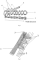
Fig. 2 is a section view of three fabric layers with integrated anchoring rings; -
Fig. 3 is a schematic diagram showing a concentrating line assisting in forming the integrated anchoring ring, wherein the main objective is to display how to form the anchoring ring, thereference sign 9 represents multiple fabric layers and specifically, may be a first fabric layer and/or a second fabric layer and/or a fourth fabric layer, without distinction being made to the specific fabric layers; -
Fig. 4 shows a three-layer fabric including the integrated anchoring ring; -
Fig. 5 is a cross section of the three-layer fabric including the integrated anchoring ring inFig. 4 , wherein thereference sign 8 represents an interweaving region among three fabric layers; -
Fig. 6 shows the three-layer fabric (with the integrated anchoring ring) in which the first fabric layer is matched with an outline of a stent, wherein thereference sign 11 represents a clipping region of the first fabric layer; -
Fig. 7 shows a fabric (which is integrated with an auxiliary valve sealing ring on the basis ofFig. 6 ) including four fabric layers inEmbodiment 2, wherein the first fabric layer is matched with an outline of the stent, and thereference sign 12 represents the auxiliary valve sealing ring; -
Fig. 8 is a cross section of the fabric inFig. 7 , wherein thereference sign 8 represents an interweaving region among four fabric layers; -
Fig. 9 is a typical surgical heart valve assembly in the prior art; -
Fig. 10 is a schematic diagram of a prosthetic valve device inEmbodiment 3, and illustrates that a heart valve assembly is assembled with a stent as a whole, wherein some components are not marked; -
Fig. 11 is an enlarged view of an A portion inFig. 10 ; and -
Fig. 12 shows the stent inEmbodiment 3, wherein the circle is not a structure on the stent, but is added for more clearly displaying a predetermined anchoring point, and thereference sign 14 represents the predetermined anchoring point. - The "" shape in the above drawings represents textile fabrics.

- 1-skirt body portion; 2-leaflet body; 3-integrated anchoring ring; 4-joint; 5-concentrating line; 6-weft yarn; 7-warp yarn; 8-interweaving region between two fabric layers or among multiple fabric layers; 9-multiple fabric layers; 10-connecting region between the leaflet body and the skirt body portion; 11-clipping region; 12-auxiliary valve sealing ring; 13-stent; 14-predetermined anchoring point.
- The technical solutions of the present application will be described in a clearly and fully understandable way in connection with the drawings. It is obvious that the described embodiments are just a part but not all of the embodiments of the present application. Based on the embodiments of the present application, those of ordinary skill in the art can obtain other embodiments, without any inventive work, which all should be within the scope of protection of the present application.
- In the description of the present application, it should be noted that directional or positional relationships indicated by terms such as "center", "upper", "lower", "left", "right", "vertical", "horizontal", "inner", and "outer" are directional or positional relationships as shown in the drawings, which are only used to facilitate description of the present application and simplify the description, but do not indicate or imply that the devices or components must have specific directions, or be constructed or operated in the specific directions, and thus cannot be construed as limiting the present application. In addition, terms such as "first", "second", and "third" are only used for description, but should not be construed as limiting or implying relative importance.
- In the description of the present application, it should be noted that unless expressly specified or defined otherwise, terms "mount", "connect" and "link" should be broadly understood. For example, connect may be fixed connection, detachable connection, or integral connection, may also be mechanical connection or electrical connection, or may be direct connection, indirect connection by a medium, or internal communication between two components. Those of ordinary skill in the art can understand specific meanings of the above terms in the present application according to specific conditions.
- In addition, the technical features involved in different embodiments of the present disclosure as described below may be combined with each other as long as they do not conflict with each other.
- A heart valve assembly, as shown in
Fig. 1 , includes askirt body portion 1 which is of a tubular structure, at least twoleaflet bodies 2 connected to the inner wall of theskirt body portion 1, and a plurality of integrated anchoring rings 3 arranged on the exterior of theskirt body portion 1. Theskirt body portion 1, theleaflet bodies 2, and the integrated anchoring rings 3 form an integral valve structure. - The
skirt body portion 1 has selvages on upper and lower sides. Two opposite sides of theleaflet body 2 respectively are an interweaving side and a free side. The interweaving side is fixed between two selvages of theskirt body portion 1 by a weaving method, and the free side is a selvage. Two opposite sides of theintegrated anchoring ring 3 respectively are an interweaving side and a free side, and the interweaving side is fixed between two selvages on the exterior of theskirt body portion 1 by the weaving method. - In the embodiment, the number of the
leaflet bodies 2 is set to be 3. - The
skirt body portion 1 provides a safe anchoring point for a valve leaflet, thereby preventing heart tissues around a valve from growing to the interior of the valve and disturbing functions of the leaflet and meanwhile, preventing perivalvular leakage. - The
integrated anchoring ring 3 plays the role of anchoring the valve assembly onto a stent. - In the embodiment, the
skirt body portion 1, theleaflet bodies 2, and the integrated anchoring rings 3 are all made of a biocompatible polymer UHMWPE. - A preparation method for the heart valve assembly (referring to
Figs. 1-6 ) is as follows. - 1) A fabric is formed by using a shuttle narrow-width electronic jacquard loom (MEGEBASSLMV). The fabric includes three fabric layers, a base layer (a first fabric layer) thereof forms the
skirt body portion 1, a second fabric layer thereof forms theleaflet bodies 2, and a third fabric layer thereof comprises rings, i.e., the anchoring rings 3, which form stent anchoring components. These layers are interwoven together in a seamless manner at predetermined positions along the length direction of the fabric. - The
synthetic leaflet bodies 2 are connected to the fabric base layer (the first fabric layer), and in the process of forming the first fabric layer, a weft yarn passes along two edges of the first fabric layer in the premise of not being cut off, so as to form the selvage. - The first fabric layer has a width of 1 mm to 50 mm, which depends on a length of a joint of the formed skirt body portion (a length of a connecting region between the
leaflet bodies 2 and the first fabric layer). The yarn used by the first fabric layer has the fineness of 5-100 deniers, which depends on a thickness and a density required by the first fabric layer. In the embodiment, the first fabric layer has the width of 50 mm, and the yarn used by the first fabric layer has the fineness of 100 deniers. - 2) At a certain point along the width direction of the first fabric layer, the second fabric layer is integrally woven into the first fabric layer by using one of a plurality of existing weaving modes (a double-layer plain orthogonal weaving mode is used in the embodiment) so as to form seamless connection between two fabric layers.
- The second fabric layer forms the synthetic leaflet bodies 2 (valve leaflets), and the
leaflet bodies 2 are formed by interweaving warp yarns with weft yarns. - At some points along the length direction of the first fabric layer, the second fabric layer and the first fabric layer are integrally connected to form attachment points. These points can be changed in the weaving process to establish a random number of geometric figures, thereby achieving the optimum performance of the valve leaflet. In the embodiment, this figure is of a straight line shape (see
Fig. 4 andFig. 6 ). - In the embodiment, the shapes of the first fabric layer and the second fabric layer are as shown in
Fig. 4 , that is, the first fabric layer is of a rectangle shape. As an alternative embodiment, the first fabric layer can be modified by cutting to form a specific shape matched with the shape of the stent (seeFig. 6 ), and meanwhile, the modifiedskirt body portion 1 can still satisfy connection with theleaflet bodies 2. - 3) On the basis of the first fabric layer and the second fabric layer, the third fabric layer is added structurally, and the third fabric layer is the
integrated anchoring ring 3 formed by the weft yarns. These weft yarn rings can be interwoven with an interweaving region between the first fabric layer and the second fabric layer along one selvage of the first fabric layer, or these weft yarn rings can be interwoven with the first fabric layer along one selvage of the first fabric layer. Staggered weaving may also be carried out at different points along the width direction of the first fabric layer. Such weft yarns extend in a transverse direction (the transverse direction herein refers to the width direction of the first fabric layer) from an interweaving point with the first fabric layer and/or the second fabric layer to a predetermined length, and these rings can be anchored on anchoring points on the surface of the stent. - In the embodiment, a specific method step for forming the
integrated anchoring ring 3 includes: guiding the weft yarn to extend in the transverse direction from the interweaving point with the selvage of the first fabric layer by a certain distance of 2 mm; and at a predetermined point, interweaving the weft yarn with one single warp yarn which is highly tightened to form one integrated anchoring ring. The one single warp yarn which is highly tightened is called as a concentrating line 5 (seeFig. 2 and Fig. 3 ). A plurality of integrated anchoring rings can be formed by repeating the above steps. The concentrating line may be made of fibers, yarns or steel wires, and in this embodiment, the concentrating line is made of the fibers. - As an alternative embodiment, the weft yarn extends in the transverse direction from the interweaving point with the selvage of the first fabric layer by a distance of 2 mm to 50 mm.
- One single concentrating
line 5 intersects with the weft yarn at a fixed point along the length direction of the first fabric layer. These concentratinglines 5 are used for assisting in forming the integrated anchoring rings, and the length of each integrated anchoring ring is finally decided by the position of the corresponding anchoring point on the stent, i.e., a final position on the stent where a prosthetic valve is attached. - Interfaces among the first fabric layer, the second fabric layer and the third fabric layer (the anchoring rings) form the seamless and integrated valve assembly. The valve assembly subsequently can be anchored onto a stent frame in a rapid and repeatable manner.
- 4) After the required numbers of valves, valve leaflets and anchoring rings are woven, a woven structure is taken down from the loom, and meanwhile, the concentrating
lines 5 maintain sufficient tension so as to ensure that the integrated anchoring rings 3 are supported and maintained. Two longitudinal (along the length direction of the first fabric layer) end portions of the first fabric layer may be connected by any suturing method, which is shown as the joint 4 inFig. 1 . The suturing method includes suturing, ultrasonic welding, heat bonding, etc. The assembly is formed to be of a cylinder or cylinder-like shape, as shown inFig. 1 . -
Embodiment 2 differs fromEmbodiment 1 in that, the heart valve assembly further includes an auxiliaryvalve sealing ring 12, and the auxiliaryvalve sealing ring 12, theskirt body portion 1, theleaflet bodies 2, and the integrated anchoring rings 3 form an integral valve structure (seeFig. 7 andFig. 8 ). A fabric is formed by using the shuttle narrow-width electronic jacquard loom. The fabric includes four fabric layers; a base layer (a first fabric layer) thereof forms theskirt body portion 1; a second fabric layer thereof forms theleaflet bodies 2; a third fabric layer thereof includes rings, i.e., the anchoring rings 3, which form stent anchoring components; and a fourth layer thereof forms a suturing ring or the auxiliaryvalve sealing ring 12 and has an interweaving side and a free side, as shown inFig. 7 . In the embodiment, along an interweaving region between the first fabric layer and the second fabric layer, the interweaving side of the fourth fabric layer is integrally woven into the interweaving region by using one of a plurality of existing weaving modes (, a double-layer plain orthogonal weaving mode is used in the embodiment) so as to form seamless connection among the four fabric layers. The fourth fabric layer is of a square shape. These layers are interwoven together in a seamless manner at predetermined positions along the length direction of the fabric. The auxiliaryvalve sealing ring 12 plays the role of making extruded contact with biological tissues around a valve prosthesis so as to ensure that perivalvular leakage cannot occur during the implant positioning and the entire service life. Tissues can also be promoted to grow to the interior of the auxiliaryvalve sealing ring 12, which will further reduce the possibility of leakage and improve the anchoring stability of the valve with passage of time. - In the embodiment, the first fabric layer is modified by cutting to form a specific shape matched with the shape of a stent (see
Fig. 7 ), and meanwhile, the modifiedskirt body portion 1 can still satisfy connection with theleaflet bodies 2. - A prosthetic valve device includes the heart valve assembly manufactured in
Embodiment 1 orEmbodiment 2 and further includes astent 13 mounted on the heart valve assembly. The stent is a surgical heart valve stent (which is configured for thoracotomy), a self-expandable catheter transportation heart valve stent (which is configured for a minimally invasive operation/TAVR), or a balloon dilatation catheter heart valve stent (which is configured for the minimally invasive operation/TAVR). In the embodiment, after being manufactured, the heart valve assembly can be treated by any post-treatment technology such as thermal forming, embedded molding, ultrasonic welding, solvent treatment, and scouring (washing with a solvent) to construct a final geometrical shape; and after construction, the heart valve assembly and the stent can be fixed. A method step for fixing the stent on the heart valve assembly depends on the geometrical shape of the stent and the structure of the heart valve assembly, and fixing between the heart valve assembly and the stent is implemented by the anchoring rings (seeFig. 10 to Fig. 12 ). In the embodiment, the method step for fixing thestent 13 on the heart valve assembly includes: hanging free ends of the anchoring rings at predetermined anchoring points 14 of the stent; and manipulating the respective integrated anchoring rings to predetermined anchoring positions on a stent frame by utilizing concentrating lines, and then removing the concentratinglines 5. The connecting process is simplified. - By adopting the heart valve assembly provided in the present application, the stent can be more conveniently aligned and positioned, so that mounting can be more accurate, simpler and more convenient, and the subjectivity is lower.
- Once the heart valve assembly is anchored onto the stent, a method for fixing the stent onto other components will depend on the shape of the stent, expected application (i.e., an aortic valve, a mitral valve, and the like) and an operating method (i.e., transcatheter transportation, open heart surgery, and the like). The rest of valve components can be fixed by various methods including, but not limited to, suturing, welding, selection placement of an adhesive, the design of a "pocket" at the skirt body portion, so as to reinforce anchoring with the stent.
- Obviously, the foregoing embodiments merely are examples for clear illustration, but not intended to limit the embodiments. Those of ordinary skill in the art also can make other different forms of variations or changes on the basis of the illustration above. It is unnecessary and impossible to enumerate all embodiments herein. The apparent variations or changes made on the basis of the embodiments of the present disclosure are still within the scope of protection of the present application.
Claims (10)
- A heart valve assembly, comprising: a skirt body portion which is of a tubular structure, at least two leaflet bodies disposed on the inner wall of the skirt body portion, and a plurality of integrated anchoring rings arranged on the exterior of the skirt body portion; one end of the integrated anchoring ring being fixedly arranged on the exterior of the skirt body portion, and the other end of the integrated anchoring ring being a free end; and the skirt body portion, the leaflet bodies and the integrated anchoring rings forming an integral valve structure.
- The heart valve assembly of claim 1, wherein one end of the integrated anchoring ring is arranged at an edge of the skirt body portion, or arranged at a random position on the exterior of the skirt body portion in the width direction thereof, or arranged in an interweaving region between the skirt body portion and one of the leaflet bodies.
- The heart valve assembly of claim 1 or 2, wherein the skirt body portion, the integrated anchoring ring and the leaflet body are made of the same or different materials, which is a biocompatible polymer; preferably, the biocompatible polymer is one or more selected from ultrahigh molecular weight polyethylene, polyethylene terephthalate, polyether ether ketone, thermoplastic polyurethane elastomer rubber, polyglycolic acid, polylactic acid-glycolic acid copolymer, polylactic acid, poly-L-lactide, polydioxanone, polyhydroxyalkanoate, and poly-glycerol-sebacate polyurethane; and more preferably, the skirt body portion, the integrated anchoring ring and the leaflet body are all made of ultrahigh molecular weight polyethylene.
- The heart valve assembly of claim 1 or 2, wherein the integrated anchoring ring has a length of 2 mm to 50 mm; and preferably, a distance between the upper and lower sides of the skirt body portion is 1 mm to 50 mm.
- The heart valve assembly of any one of claims 1-4, further comprising an auxiliary valve sealing ring, wherein the skirt body portion, the leaflet bodies, the integrated anchoring rings and the auxiliary valve sealing ring form an integral valve structure.
- A preparation method for a heart valve assembly, wherein a fabric is formed by using a shuttle narrow-width electronic jacquard loom; the fabric comprises three fabric layers, a first fabric layer thereof forms a skirt body portion, a second fabric layer thereof forms leaflet bodies, and a third fabric layer thereof forms rings which are integrated anchoring rings; and these layers are interwoven together in a seamless manner at predetermined positions along the length direction of the fabric.
- The preparation method for the heart valve assembly of claim 6, wherein a method step for forming the second fabric layer comprises: at a certain point along the width direction of the first fabric layer, integrally weaving the second fabric layer into the first fabric layer by using any existing weaving mode, so as to form seamless connection between two fabric layers.
- The preparation method for the heart valve assembly of claim 6 or 7, wherein a specific method step for forming the integrated anchoring ring comprises: guiding a weft yarn to extend in a transverse direction from an interweaving point with a selvage of the first fabric layer by a certain distance of 2 mm to 50 mm; and at a predetermined point, interweaving the weft yarn with one single warp yarn which is highly tightened to form the integrated anchoring ring; wherein the transverse direction is the width direction of the first fabric layer.
- The preparation method for the heart valve assembly of claim 8, wherein the weft yarn extends in the transverse direction from the interweaving point with the selvage of the first fabric layer by a certain distance of 2 mm.
- A prosthetic valve device, comprising the heart valve assembly of any one of claims 1-5 or a heart valve assembly produced by the preparation method of any one of claims 6-9, and further comprising a stent mounted on the heart valve assembly.
Applications Claiming Priority (2)
| Application Number | Priority Date | Filing Date | Title |
|---|---|---|---|
| CN202010790457.2A CN114052988A (en) | 2020-08-07 | 2020-08-07 | Heart valve assembly and preparation method thereof |
| PCT/CN2021/111111 WO2022028564A1 (en) | 2020-08-07 | 2021-08-06 | Heart valve assembly and preparation method therefor |
Publications (3)
| Publication Number | Publication Date |
|---|---|
| EP4193964A1 true EP4193964A1 (en) | 2023-06-14 |
| EP4193964A4 EP4193964A4 (en) | 2024-01-24 |
| EP4193964B1 EP4193964B1 (en) | 2025-10-01 |
Family
ID=80117073
Family Applications (1)
| Application Number | Title | Priority Date | Filing Date |
|---|---|---|---|
| EP21853961.7A Active EP4193964B1 (en) | 2020-08-07 | 2021-08-06 | Heart valve assembly and preparation method therefor |
Country Status (5)
| Country | Link |
|---|---|
| US (1) | US20230263625A1 (en) |
| EP (1) | EP4193964B1 (en) |
| JP (1) | JP7504516B2 (en) |
| CN (1) | CN114052988A (en) |
| WO (1) | WO2022028564A1 (en) |
Families Citing this family (1)
| Publication number | Priority date | Publication date | Assignee | Title |
|---|---|---|---|---|
| EP4239115B1 (en) * | 2017-08-11 | 2025-08-20 | Edwards Lifesciences Corporation | Sealing element for prosthetic heart valve |
Family Cites Families (16)
| Publication number | Priority date | Publication date | Assignee | Title |
|---|---|---|---|---|
| US4222126A (en) * | 1978-12-14 | 1980-09-16 | The United States Of America As Represented By The Secretary Of The Department Of Health, Education & Welfare | Unitized three leaflet heart valve |
| JP2001505807A (en) * | 1996-12-10 | 2001-05-08 | パーデュー・リサーチ・ファウンデーション | Artificial vascular valve |
| WO2010020660A1 (en) * | 2008-08-19 | 2010-02-25 | Dsm Ip Assets B.V. | Implantable valve prosthesis and method for manufacturing such a valve |
| US8795357B2 (en) * | 2011-07-15 | 2014-08-05 | Edwards Lifesciences Corporation | Perivalvular sealing for transcatheter heart valve |
| US11202704B2 (en) * | 2011-10-19 | 2021-12-21 | Twelve, Inc. | Prosthetic heart valve devices, prosthetic mitral valves and associated systems and methods |
| CN103006352B (en) * | 2012-12-24 | 2015-05-13 | 杭州启明医疗器械有限公司 | Prosthesis valve and prosthesis valve device |
| US20150209141A1 (en) * | 2014-01-24 | 2015-07-30 | St. Jude Medical, Cardiology Division, Inc. | Stationary intra-annular halo designs for paravalvular leak (pvl) reduction-passive channel filling cuff designs |
| EP3139861B1 (en) * | 2014-05-06 | 2020-05-27 | DSM IP Assets B.V. | Method of making a prosthetic valve and valve obtained therewith |
| CN110090094B (en) * | 2014-05-06 | 2021-09-14 | 帝斯曼知识产权资产管理有限公司 | Prosthetic valve and method of manufacturing a prosthetic valve |
| CA2975361A1 (en) * | 2015-02-02 | 2016-08-11 | Symetis Sa | Stent seals and method of production |
| US10588741B2 (en) * | 2015-11-06 | 2020-03-17 | Micor Limited | Mitral valve prosthesis |
| CN105581858B (en) * | 2015-12-15 | 2018-04-10 | 先健科技(深圳)有限公司 | Prosthetic heart valve holder and heart valve prosthesis |
| CN108245281A (en) * | 2016-12-28 | 2018-07-06 | 上海微创心通医疗科技有限公司 | Valve prosthesis |
| EP4239115B1 (en) * | 2017-08-11 | 2025-08-20 | Edwards Lifesciences Corporation | Sealing element for prosthetic heart valve |
| CN111195166A (en) * | 2020-01-14 | 2020-05-26 | 启晨(上海)医疗器械有限公司 | Knittable heart valve device and manufacturing method and using method thereof |
| CN212940074U (en) * | 2020-08-07 | 2021-04-13 | 山前(珠海)生物材料科技有限公司 | Heart valve assembly and heart valve device |
-
2020
- 2020-08-07 CN CN202010790457.2A patent/CN114052988A/en active Pending
-
2021
- 2021-08-06 US US18/020,100 patent/US20230263625A1/en active Pending
- 2021-08-06 EP EP21853961.7A patent/EP4193964B1/en active Active
- 2021-08-06 JP JP2023508056A patent/JP7504516B2/en active Active
- 2021-08-06 WO PCT/CN2021/111111 patent/WO2022028564A1/en not_active Ceased
Also Published As
| Publication number | Publication date |
|---|---|
| CN114052988A (en) | 2022-02-18 |
| JP2023537029A (en) | 2023-08-30 |
| US20230263625A1 (en) | 2023-08-24 |
| WO2022028564A1 (en) | 2022-02-10 |
| JP7504516B2 (en) | 2024-06-24 |
| EP4193964B1 (en) | 2025-10-01 |
| EP4193964A4 (en) | 2024-01-24 |
Similar Documents
| Publication | Publication Date | Title |
|---|---|---|
| US11266498B2 (en) | Method of making a prosthetic valve and valve obtained therewith | |
| JP6690834B2 (en) | Artificial valve and method of manufacturing artificial valve | |
| US10583003B2 (en) | Method of making a prosthetic valve and valve obtained therewith | |
| EP3139863B1 (en) | Prosthetic valve and method for making same | |
| EP4137093B1 (en) | Heart valve prosthesis, artificial valve formed by same, and preparation method therefor | |
| CN212940074U (en) | Heart valve assembly and heart valve device | |
| CN220512957U (en) | Implantable medical device | |
| EP4193964B1 (en) | Heart valve assembly and preparation method therefor | |
| CN212913479U (en) | Heart valve prosthesis and artificial valve formed by same | |
| CN110090094B (en) | Prosthetic valve and method of manufacturing a prosthetic valve | |
| EP4497412A1 (en) | Aortic implant with proximal anchoring layer |
Legal Events
| Date | Code | Title | Description |
|---|---|---|---|
| STAA | Information on the status of an ep patent application or granted ep patent |
Free format text: STATUS: THE INTERNATIONAL PUBLICATION HAS BEEN MADE |
|
| PUAI | Public reference made under article 153(3) epc to a published international application that has entered the european phase |
Free format text: ORIGINAL CODE: 0009012 |
|
| STAA | Information on the status of an ep patent application or granted ep patent |
Free format text: STATUS: REQUEST FOR EXAMINATION WAS MADE |
|
| 17P | Request for examination filed |
Effective date: 20230210 |
|
| AK | Designated contracting states |
Kind code of ref document: A1 Designated state(s): AL AT BE BG CH CY CZ DE DK EE ES FI FR GB GR HR HU IE IS IT LI LT LU LV MC MK MT NL NO PL PT RO RS SE SI SK SM TR |
|
| DAV | Request for validation of the european patent (deleted) | ||
| DAX | Request for extension of the european patent (deleted) | ||
| A4 | Supplementary search report drawn up and despatched |
Effective date: 20240102 |
|
| RIC1 | Information provided on ipc code assigned before grant |
Ipc: A61F 2/24 20060101AFI20231220BHEP |
|
| GRAP | Despatch of communication of intention to grant a patent |
Free format text: ORIGINAL CODE: EPIDOSNIGR1 |
|
| STAA | Information on the status of an ep patent application or granted ep patent |
Free format text: STATUS: GRANT OF PATENT IS INTENDED |
|
| INTG | Intention to grant announced |
Effective date: 20241220 |
|
| GRAJ | Information related to disapproval of communication of intention to grant by the applicant or resumption of examination proceedings by the epo deleted |
Free format text: ORIGINAL CODE: EPIDOSDIGR1 |
|
| STAA | Information on the status of an ep patent application or granted ep patent |
Free format text: STATUS: REQUEST FOR EXAMINATION WAS MADE |
|
| INTC | Intention to grant announced (deleted) | ||
| GRAP | Despatch of communication of intention to grant a patent |
Free format text: ORIGINAL CODE: EPIDOSNIGR1 |
|
| STAA | Information on the status of an ep patent application or granted ep patent |
Free format text: STATUS: GRANT OF PATENT IS INTENDED |
|
| INTG | Intention to grant announced |
Effective date: 20250526 |
|
| GRAS | Grant fee paid |
Free format text: ORIGINAL CODE: EPIDOSNIGR3 |
|
| GRAA | (expected) grant |
Free format text: ORIGINAL CODE: 0009210 |
|
| STAA | Information on the status of an ep patent application or granted ep patent |
Free format text: STATUS: THE PATENT HAS BEEN GRANTED |
|
| AK | Designated contracting states |
Kind code of ref document: B1 Designated state(s): AL AT BE BG CH CY CZ DE DK EE ES FI FR GB GR HR HU IE IS IT LI LT LU LV MC MK MT NL NO PL PT RO RS SE SI SK SM TR |
|
| REG | Reference to a national code |
Ref country code: GB Ref legal event code: FG4D Ref country code: CH Ref legal event code: F10 Free format text: ST27 STATUS EVENT CODE: U-0-0-F10-F00 (AS PROVIDED BY THE NATIONAL OFFICE) Effective date: 20251001 |
|
| REG | Reference to a national code |
Ref country code: DE Ref legal event code: R096 Ref document number: 602021039745 Country of ref document: DE |
|
| REG | Reference to a national code |
Ref country code: IE Ref legal event code: FG4D |
|
| REG | Reference to a national code |
Ref country code: NL Ref legal event code: MP Effective date: 20251001 |
|
| REG | Reference to a national code |
Ref country code: AT Ref legal event code: MK05 Ref document number: 1841783 Country of ref document: AT Kind code of ref document: T Effective date: 20251001 |
|
| PG25 | Lapsed in a contracting state [announced via postgrant information from national office to epo] |
Ref country code: NL Free format text: LAPSE BECAUSE OF FAILURE TO SUBMIT A TRANSLATION OF THE DESCRIPTION OR TO PAY THE FEE WITHIN THE PRESCRIBED TIME-LIMIT Effective date: 20251001 |
|
| PG25 | Lapsed in a contracting state [announced via postgrant information from national office to epo] |
Ref country code: ES Free format text: LAPSE BECAUSE OF FAILURE TO SUBMIT A TRANSLATION OF THE DESCRIPTION OR TO PAY THE FEE WITHIN THE PRESCRIBED TIME-LIMIT Effective date: 20251001 |
|
| REG | Reference to a national code |
Ref country code: LT Ref legal event code: MG9D |
|
| PG25 | Lapsed in a contracting state [announced via postgrant information from national office to epo] |
Ref country code: NO Free format text: LAPSE BECAUSE OF FAILURE TO SUBMIT A TRANSLATION OF THE DESCRIPTION OR TO PAY THE FEE WITHIN THE PRESCRIBED TIME-LIMIT Effective date: 20260101 |
|
| PG25 | Lapsed in a contracting state [announced via postgrant information from national office to epo] |
Ref country code: HR Free format text: LAPSE BECAUSE OF FAILURE TO SUBMIT A TRANSLATION OF THE DESCRIPTION OR TO PAY THE FEE WITHIN THE PRESCRIBED TIME-LIMIT Effective date: 20251001 Ref country code: FI Free format text: LAPSE BECAUSE OF FAILURE TO SUBMIT A TRANSLATION OF THE DESCRIPTION OR TO PAY THE FEE WITHIN THE PRESCRIBED TIME-LIMIT Effective date: 20251001 Ref country code: AT Free format text: LAPSE BECAUSE OF FAILURE TO SUBMIT A TRANSLATION OF THE DESCRIPTION OR TO PAY THE FEE WITHIN THE PRESCRIBED TIME-LIMIT Effective date: 20251001 |
|
| PG25 | Lapsed in a contracting state [announced via postgrant information from national office to epo] |
Ref country code: RS Free format text: LAPSE BECAUSE OF FAILURE TO SUBMIT A TRANSLATION OF THE DESCRIPTION OR TO PAY THE FEE WITHIN THE PRESCRIBED TIME-LIMIT Effective date: 20260101 |
|
| PG25 | Lapsed in a contracting state [announced via postgrant information from national office to epo] |
Ref country code: IS Free format text: LAPSE BECAUSE OF FAILURE TO SUBMIT A TRANSLATION OF THE DESCRIPTION OR TO PAY THE FEE WITHIN THE PRESCRIBED TIME-LIMIT Effective date: 20260201 |
|
| PG25 | Lapsed in a contracting state [announced via postgrant information from national office to epo] |
Ref country code: PT Free format text: LAPSE BECAUSE OF FAILURE TO SUBMIT A TRANSLATION OF THE DESCRIPTION OR TO PAY THE FEE WITHIN THE PRESCRIBED TIME-LIMIT Effective date: 20260202 Ref country code: CZ Free format text: LAPSE BECAUSE OF FAILURE TO SUBMIT A TRANSLATION OF THE DESCRIPTION OR TO PAY THE FEE WITHIN THE PRESCRIBED TIME-LIMIT Effective date: 20251001 |
|
| PG25 | Lapsed in a contracting state [announced via postgrant information from national office to epo] |
Ref country code: PL Free format text: LAPSE BECAUSE OF FAILURE TO SUBMIT A TRANSLATION OF THE DESCRIPTION OR TO PAY THE FEE WITHIN THE PRESCRIBED TIME-LIMIT Effective date: 20251001 |
|
| PG25 | Lapsed in a contracting state [announced via postgrant information from national office to epo] |
Ref country code: LV Free format text: LAPSE BECAUSE OF FAILURE TO SUBMIT A TRANSLATION OF THE DESCRIPTION OR TO PAY THE FEE WITHIN THE PRESCRIBED TIME-LIMIT Effective date: 20251001 |
|
| PG25 | Lapsed in a contracting state [announced via postgrant information from national office to epo] |
Ref country code: BG Free format text: LAPSE BECAUSE OF FAILURE TO SUBMIT A TRANSLATION OF THE DESCRIPTION OR TO PAY THE FEE WITHIN THE PRESCRIBED TIME-LIMIT Effective date: 20251001 |