EP4192646B1 - Machine tool with two independent carriages - Google Patents
Machine tool with two independent carriages Download PDFInfo
- Publication number
- EP4192646B1 EP4192646B1 EP21765706.3A EP21765706A EP4192646B1 EP 4192646 B1 EP4192646 B1 EP 4192646B1 EP 21765706 A EP21765706 A EP 21765706A EP 4192646 B1 EP4192646 B1 EP 4192646B1
- Authority
- EP
- European Patent Office
- Prior art keywords
- carriages
- axis
- slide
- motor
- machine tool
- Prior art date
- Legal status (The legal status is an assumption and is not a legal conclusion. Google has not performed a legal analysis and makes no representation as to the accuracy of the status listed.)
- Active
Links
Images



Classifications
-
- B—PERFORMING OPERATIONS; TRANSPORTING
- B23—MACHINE TOOLS; METAL-WORKING NOT OTHERWISE PROVIDED FOR
- B23Q—DETAILS, COMPONENTS, OR ACCESSORIES FOR MACHINE TOOLS, e.g. ARRANGEMENTS FOR COPYING OR CONTROLLING; MACHINE TOOLS IN GENERAL CHARACTERISED BY THE CONSTRUCTION OF PARTICULAR DETAILS OR COMPONENTS; COMBINATIONS OR ASSOCIATIONS OF METAL-WORKING MACHINES, NOT DIRECTED TO A PARTICULAR RESULT
- B23Q1/00—Members which are comprised in the general build-up of a form of machine, particularly relatively large fixed members
- B23Q1/01—Frames, beds, pillars or like members; Arrangement of ways
- B23Q1/012—Portals
-
- B—PERFORMING OPERATIONS; TRANSPORTING
- B23—MACHINE TOOLS; METAL-WORKING NOT OTHERWISE PROVIDED FOR
- B23Q—DETAILS, COMPONENTS, OR ACCESSORIES FOR MACHINE TOOLS, e.g. ARRANGEMENTS FOR COPYING OR CONTROLLING; MACHINE TOOLS IN GENERAL CHARACTERISED BY THE CONSTRUCTION OF PARTICULAR DETAILS OR COMPONENTS; COMBINATIONS OR ASSOCIATIONS OF METAL-WORKING MACHINES, NOT DIRECTED TO A PARTICULAR RESULT
- B23Q1/00—Members which are comprised in the general build-up of a form of machine, particularly relatively large fixed members
- B23Q1/01—Frames, beds, pillars or like members; Arrangement of ways
- B23Q1/017—Arrangements of ways
-
- B—PERFORMING OPERATIONS; TRANSPORTING
- B23—MACHINE TOOLS; METAL-WORKING NOT OTHERWISE PROVIDED FOR
- B23Q—DETAILS, COMPONENTS, OR ACCESSORIES FOR MACHINE TOOLS, e.g. ARRANGEMENTS FOR COPYING OR CONTROLLING; MACHINE TOOLS IN GENERAL CHARACTERISED BY THE CONSTRUCTION OF PARTICULAR DETAILS OR COMPONENTS; COMBINATIONS OR ASSOCIATIONS OF METAL-WORKING MACHINES, NOT DIRECTED TO A PARTICULAR RESULT
- B23Q1/00—Members which are comprised in the general build-up of a form of machine, particularly relatively large fixed members
- B23Q1/25—Movable or adjustable work or tool supports
- B23Q1/44—Movable or adjustable work or tool supports using particular mechanisms
- B23Q1/56—Movable or adjustable work or tool supports using particular mechanisms with sliding pairs only, the sliding pairs being the first two elements of the mechanism
- B23Q1/60—Movable or adjustable work or tool supports using particular mechanisms with sliding pairs only, the sliding pairs being the first two elements of the mechanism two sliding pairs only, the sliding pairs being the first two elements of the mechanism
- B23Q1/62—Movable or adjustable work or tool supports using particular mechanisms with sliding pairs only, the sliding pairs being the first two elements of the mechanism two sliding pairs only, the sliding pairs being the first two elements of the mechanism with perpendicular axes, e.g. cross-slides
- B23Q1/621—Movable or adjustable work or tool supports using particular mechanisms with sliding pairs only, the sliding pairs being the first two elements of the mechanism two sliding pairs only, the sliding pairs being the first two elements of the mechanism with perpendicular axes, e.g. cross-slides a single sliding pair followed perpendicularly by a single sliding pair
-
- B—PERFORMING OPERATIONS; TRANSPORTING
- B23—MACHINE TOOLS; METAL-WORKING NOT OTHERWISE PROVIDED FOR
- B23Q—DETAILS, COMPONENTS, OR ACCESSORIES FOR MACHINE TOOLS, e.g. ARRANGEMENTS FOR COPYING OR CONTROLLING; MACHINE TOOLS IN GENERAL CHARACTERISED BY THE CONSTRUCTION OF PARTICULAR DETAILS OR COMPONENTS; COMBINATIONS OR ASSOCIATIONS OF METAL-WORKING MACHINES, NOT DIRECTED TO A PARTICULAR RESULT
- B23Q5/00—Driving or feeding mechanisms; Control arrangements therefor
- B23Q5/22—Feeding members carrying tools or work
- B23Q5/34—Feeding other members supporting tools or work, e.g. saddles, tool-slides, through mechanical transmission
- B23Q5/38—Feeding other members supporting tools or work, e.g. saddles, tool-slides, through mechanical transmission feeding continuously
- B23Q5/385—Feeding other members supporting tools or work, e.g. saddles, tool-slides, through mechanical transmission feeding continuously using a gear and rack mechanism or a friction wheel co-operating with a rail
-
- B—PERFORMING OPERATIONS; TRANSPORTING
- B23—MACHINE TOOLS; METAL-WORKING NOT OTHERWISE PROVIDED FOR
- B23C—MILLING
- B23C1/00—Milling machines not designed for particular work or special operations
- B23C1/002—Gantry-type milling machines
-
- B—PERFORMING OPERATIONS; TRANSPORTING
- B23—MACHINE TOOLS; METAL-WORKING NOT OTHERWISE PROVIDED FOR
- B23Q—DETAILS, COMPONENTS, OR ACCESSORIES FOR MACHINE TOOLS, e.g. ARRANGEMENTS FOR COPYING OR CONTROLLING; MACHINE TOOLS IN GENERAL CHARACTERISED BY THE CONSTRUCTION OF PARTICULAR DETAILS OR COMPONENTS; COMBINATIONS OR ASSOCIATIONS OF METAL-WORKING MACHINES, NOT DIRECTED TO A PARTICULAR RESULT
- B23Q5/00—Driving or feeding mechanisms; Control arrangements therefor
- B23Q5/54—Arrangements or details not restricted to group B23Q5/02 or group B23Q5/22 respectively, e.g. control handles
- B23Q5/56—Preventing backlash
-
- Y—GENERAL TAGGING OF NEW TECHNOLOGICAL DEVELOPMENTS; GENERAL TAGGING OF CROSS-SECTIONAL TECHNOLOGIES SPANNING OVER SEVERAL SECTIONS OF THE IPC; TECHNICAL SUBJECTS COVERED BY FORMER USPC CROSS-REFERENCE ART COLLECTIONS [XRACs] AND DIGESTS
- Y10—TECHNICAL SUBJECTS COVERED BY FORMER USPC
- Y10T—TECHNICAL SUBJECTS COVERED BY FORMER US CLASSIFICATION
- Y10T409/00—Gear cutting, milling, or planing
- Y10T409/30—Milling
- Y10T409/30784—Milling including means to adustably position cutter
- Y10T409/307952—Linear adjustment
- Y10T409/308288—Linear adjustment including gantry-type cutter-carrier
-
- Y—GENERAL TAGGING OF NEW TECHNOLOGICAL DEVELOPMENTS; GENERAL TAGGING OF CROSS-SECTIONAL TECHNOLOGIES SPANNING OVER SEVERAL SECTIONS OF THE IPC; TECHNICAL SUBJECTS COVERED BY FORMER USPC CROSS-REFERENCE ART COLLECTIONS [XRACs] AND DIGESTS
- Y10—TECHNICAL SUBJECTS COVERED BY FORMER USPC
- Y10T—TECHNICAL SUBJECTS COVERED BY FORMER US CLASSIFICATION
- Y10T409/00—Gear cutting, milling, or planing
- Y10T409/30—Milling
- Y10T409/309576—Machine frame
Definitions
- the invention relates to a machine tool.
- the invention has its preferred application in a computerized numerical control (CNC) milling machine having members that are movable along coordinated axes in order to move a milling tool within a work volume, to which reference will be made in the description below without because of this loosing in generality.
- CNC computerized numerical control
- CNC milling machines were developed, which are provided with movable members with different degrees of freedom, so as to allow for a great flexibility in the machining of a piece to be processed.
- known milling machines can be programmed so as to carry out a wide range of different machining operations, depending on special needs.
- US 2014/020526 , EP 1750899 and EP 1362664 disclose respective examples of milling machines and documents US 2902875 and JP H10228317 disclose respective high-precision drive and transmission assembly to avoid backslashes.
- the machine tool of US 2014/020526 comprises two carriages arranged at a fixed distance with respect to each other and slidable together along a guide element; and a slide interposed between the two carriages, carried by the two carriages and slidable in relation to the two carriages; wherein said carriages are independent and mechanically linked together solely by said slide.
- known milling machines comprise a plurality of members that are movable according to coordinated axes.
- These members can comprise, for example, a carriage that can slide along a guide in a first direction, for example a horizontal one, and a slide carried by the carriage in a projecting manner and movable, relative to the latter, along a second direction perpendicular to the first direction, for example a vertical one.
- the carriage typically has a "cross-like" shape, since it has, on a first face of its, a first seat along an axis for the coupling to the guide and, on a second face of its opposite the first one, a second seat orthogonal to the first seat for the coupling to the slide.
- the object of the invention is to at least partly overcome the drawbacks of the prior art.
- the object of the invention is to provide a lighter machine tool with a smaller cost, which is capable of carrying out high-speed machining operations, ensuring at the same time a suitable quality of the machining.
- a machine tool comprising:
- the bending moment acting upon the guide element is limited by the fact that the slide is arranged between the two carriages and, hence, can be placed close to the guide element.
- the required precision being the same, the weight and the cost of the machine can be reduced.
- the two motors are controlled so as to exert opposite torques with a high modulus upon the respective toothed wheels so as to obtain a high-stiffness connection between the carriages and the slide.
- the two motors are configured to exert opposite torques with a smaller modulus upon the respective toothed wheels so as to obtain a connection between the carriages and the slide with a smaller stiffness, thus limiting wear.
- the slide carries a machining head.
- the guide element comprises at least one rail extending in a direction parallel to the first axis and each one of the carriages comprises at least one runner coupled to the rail in a sliding manner along the direction of the first axis and in a rigid manner in a direction perpendicular to the first axis.
- the slide comprises a second rack extending in a direction substantially parallel to the second axis; at least one of the two carriages comprising at least one motor provided with a toothed wheel, which meshes with the second rack so as to control the sliding of the slide along the second rack.
- one of the two carriages comprises a third motor and a fourth motor, which are provided with respective toothed wheels, which mesh with the second rack and are configured to exert respective torques in opposite direction upon the respective toothed wheels.
- one of the two carriages comprises a third motor and the other one of the two carriages comprises a fourth motor, said third and fourth motor being provided with respective toothed wheels, which mesh with the second rack and are configured to exert respective torques in opposite directions upon the respective toothed wheels.
- number 1 indicates, as a whole, a machine tool, in particular a milling machine, preferably a CNC milling machine.
- the milling machine 1 comprises a substantially straight guide element 2 extending along an axis A1, for example a horizontal one; two carriages 3 and 4, which are arranged at a fixed distance D from one another along the guide element 2 and are capable of sliding together along the guide element 2; a slide 5, which is interposed between the carriages 3 and 4, is carried by the carriages 3 and 4 and can slide relative to the carriages 3 and 4 along an axis A2 perpendicular to the axis A1, in particular a vertical one; and a milling head 6, which is carried by the slide 5 and is configured to carry a milling tool (which is not shown in the accompanying Figures).
- the guide element 2 is supported by a fixed or movable support structure, which is not shown in the accompanying figures because it is not part of the invention.
- said support structure can assume different configurations.
- the support structure comprises two vertical supports, each fixed to a respective end of the guide element 2, so as to define a gantry milling machine 1.
- the guide element 2 comprises a rail 7 and a rail 8, each extending in a direction that is substantially parallel to the axis A1.
- the rails 7 and 8 have a section shaped like a dovetail.
- the guide element 2 can comprise only one rail extending in a direction parallel to the axis A1.
- the number of rails of the guide element 2 can change and is not limited by the invention.
- the guide element 2 comprises a rack 9 extending in a direction that is parallel to the axis A1 and, hence, parallel to the rails 7 and 8.
- each one of the carriages 3 and 4 comprises four runners 10, two of them being configured to slide on the rail 7 and the other two being configured to slide on the rail 8.
- each runner 10 is shaped so as to be coupled to the dovetail-shaped section of the rails 7 and 8 in a sliding manner along the direction of the axis A1 and in a rigid manner in the directions orthogonal to the axis A1, so as to only allow the carriages 3 and 4 to slide along the rails 7 and 8 and avoid the relative movement of the carriages 3 and 4 relative to the guide element 2 in all other directions.
- each carriage 3 and 4 is provided with only two runners 10, one of them being configured to slide on the rail 7 and the other one being configured to slide on the rail 8.
- the number of runners 10 of the two carriages 3 and 4 can change and is not limited by the invention.
- the carriage 3 comprises an electric motor 11 and the carriage 4 comprises an electric motor 12.
- Each electric motor 11, 12 is provided with a respective toothed wheel 13 ( Figures 3 and 5 ), which meshes with the rack 9 ( Figures 3 and 5 ).
- the motors 11 and 12 are configured to exert respective torques in opposite directions upon the respective toothed wheels 13 ( Figures 3 and 5 ) so as to limit the clearances of the coupling between the toothed wheels 13 ( Figures 3 and 5 ) and the rack 9 ( Figures 3 and 5 ).
- the slide 5 is oblong in the direction A2, has a substantially rectangular section and comprises at least two rails 14 and 15, each facing the respective carriage 3, 4 and extending in a direction that is parallel to the axis A2.
- the rails 14 and 15 have a section shaped like a dovetail.
- Each carriage 3, 4 comprises at least one slider 16, which is configured to slide along the respective rail 14, 15.
- each slider 16 is shaped so as to be coupled to the dovetail-shaped section of the rails 14 and 15 in a sliding manner along the direction of the axis A2 and in a rigid manner in the directions orthogonal to the axis A2, so as to only allow the slide 5 to slide along the axis A2 and avoid the relative movement of the slide 5 relative to the carriages 3 and 4 in all other directions.
- the slide 5 comprises two rails 14 and two rails 15.
- the carriage 3 comprises eight sliders 16, four of them being configured to slide on one of the two rails 14 and four of them being configured to slide on the other one of the two rails 14.
- the carriage 4 comprises eight sliders 16, four of them being configured to slide on one of the two rails 15 and four of them being configured to slide on the other one of the two rails 15.
- the number of rails 14 and 15 and of sliders 16 can change and is not limited by the invention.
- the slide 5 comprises two racks 17, each extending in a direction that is parallel to the axis A2 and, hence, parallel to the rails 14 and 15.
- the carriage 3 comprises an electric motor 18 and the carriage 4 comprises an electric motor 19.
- Each electric motor 18, 19 is provided with a respective toothed wheel 20, which meshes with the respective rack 17.
- the motors 18 and 19 are configured to exert respective torques in opposite directions upon the respective toothed wheels 20 so as to limit the clearances of the coupling between the toothed wheels 20 and the rack 17.
- the sole carriage 3 comprises a motor.
- the milling head 6 comprises two bodies 21 and 22, which are articulated to one another, and a milling tool, which is carried by the body 22 and is not shown in the accompanying Figures.
- the body 21 is connected to the slide 5 so as to rotate relative to the slide 5 around the axis A2 and the body 22 is connected to the body 21 so as to slide relative to the body 21 around an axis A3 that is perpendicular to the axis A2.
- the milling head 6 comprises motors and/or actuators, which are not shown in the accompanying Figures and are configured to move the bodies 21 and 22 and to start the rotation of the milling tool, which is not shown in the accompanying Figures.
- the axis A1 of the guide element 2 is horizontal and the axis A2 is vertical; according to a variant of the invention, which is not shown in the accompanying Figures, the axis A1 could be vertical and the axis A2 could be horizontal.
- the motors 11 and 12 start the sliding of the carriages 3 and 4 along the guide element 2.
- the power of one of the motors 11 and 12 is increased so as to increase the torque of one of the two motors 11 and 12 compared to the other one of the two motors 11 and 12.
- the power of the other one of the two motors 11 and 12 is increased.
- the motors 11 and 12 control, in a coordinated manner, the torques exerted upon the respective toothed wheels 13 so as to modulate the stiffness of the connection between the carriages 3, 4 and the slide 5 depending on the forces involved.
- the motors 18 and 19 start the sliding of the slide 5 relative to the carriages 3 and 4 in the direction of the axis A2.
- the bodies 21 and 22 are oriented so as to move the milling tool, which is not shown in the accompanying Figures, within a work volume based on the specific machining needs.
- Figures 7 shows a variant in which the slide 5 has a tapered section, instead of a substantially rectangular one; therefore, the two rails 14 and the two rails 15 on the opposite sides of the slide 5 are not coplanar to one another, but are staggered in a direction parallel to the axis A1.
- the carriages 3, 4 are shaped in a corresponding manner, on their side facing the slide 5, and the sliders 16 of each carriage 3, 4 are arranged on planes which, in turn, are staggered in order to cooperate with the corresponding rails 14 or 15.
- the motors controlling the movement of the carriages 3, 4 along the axis A1 and the sliding of the slide 5 along the axis A2 could be hydraulic or pneumatic motors.
Landscapes
- Engineering & Computer Science (AREA)
- Mechanical Engineering (AREA)
- Machine Tool Units (AREA)
Description
- The invention relates to a machine tool.
- The invention has its preferred application in a computerized numerical control (CNC) milling machine having members that are movable along coordinated axes in order to move a milling tool within a work volume, to which reference will be made in the description below without because of this loosing in generality.
- In the last decades, CNC milling machines were developed, which are provided with movable members with different degrees of freedom, so as to allow for a great flexibility in the machining of a piece to be processed. In particular, known milling machines can be programmed so as to carry out a wide range of different machining operations, depending on special needs.
- Documents
US 2014/020526 ,EP 1750899 andEP 1362664 disclose respective examples of milling machines and documentsUS 2902875 andJP H10228317 US 2014/020526 comprises two carriages arranged at a fixed distance with respect to each other and slidable together along a guide element; and a slide interposed between the two carriages, carried by the two carriages and slidable in relation to the two carriages; wherein said carriages are independent and mechanically linked together solely by said slide. - In order to fulfil the requirements mentioned above, known milling machines comprise a plurality of members that are movable according to coordinated axes. These members can comprise, for example, a carriage that can slide along a guide in a first direction, for example a horizontal one, and a slide carried by the carriage in a projecting manner and movable, relative to the latter, along a second direction perpendicular to the first direction, for example a vertical one.
- Hence, the carriage typically has a "cross-like" shape, since it has, on a first face of its, a first seat along an axis for the coupling to the guide and, on a second face of its opposite the first one, a second seat orthogonal to the first seat for the coupling to the slide.
- Since the two seats cannot intersect one another, this necessarily leads to a projecting arrangement of the slide (and, hence, of the milling head) relative to the guide of the carriage. As a consequence, the weight of the carriage and of the slide, as well as the forces exchanged with the piece during the machining, determine significant bending moments relative to the guide, with potentially negative effects on the machining precision. In order to avoid these effects, the members of the machine need to be properly sized so as to ensure the necessary stiffness thereof, which leads to an increase in the weight and in the cost of the components as well as to dynamic problems.
- The object of the invention is to at least partly overcome the drawbacks of the prior art.
- In particular, the object of the invention is to provide a lighter machine tool with a smaller cost, which is capable of carrying out high-speed machining operations, ensuring at the same time a suitable quality of the machining.
- According to the invention, there is provided a machine tool comprising:
- a substantially straight guide element extending along a first axis and comprising a first rack extending in a direction parallel to the first axis;
- two carriages, which are arranged at a fixed distance from one another along the guide element and are capable of sliding together along the guide element, at least one of the two carriages comprising at least one motor fitted with a toothed wheel which engages with the first rack; and
- a slide, which is interposed between the two carriages, is carried by the two carriages and can slide relative to the two carriages along a second axis substantially perpendicular to the first axis;
- wherein said carriages are independent and are mechanically connected to one another solely by means of said slide;
- wherein one of the two carriages comprises a first motor and the other of the two carriages comprises a second motor, the first and second motors being fitted with respective toothed wheels which mesh with the first rack and are configured to exert respective torques in opposite directions upon the respective toothed wheels; and
- wherein the first and the second motor are configured to control, in a coordinated manner, the torques exerted upon the respective toothed wheels so as to modulate the stiffness of the connection between the carriages and the slide in a direction substantially parallel to the first axis.
- Thanks to the invention, the bending moment acting upon the guide element is limited by the fact that the slide is arranged between the two carriages and, hence, can be placed close to the guide element.
- In this way, the guide element and the relative support structure are not subjected to significant deformations, thus ensuring better performances in terms of machining precision.
- Alternatively, the required precision being the same, the weight and the cost of the machine can be reduced.
- Furthermore, thanks to the fact that the two carriages are independent of one another, by controlling the sliding of the two carriages along the guide element it is possible to ensure an adequate stiffness of the machine in order to fulfil requirements set by different operating conditions.
- Basically, during rough-milling operations involving great forces, the two motors are controlled so as to exert opposite torques with a high modulus upon the respective toothed wheels so as to obtain a high-stiffness connection between the carriages and the slide.
- During superficial finishing operations involving smaller forces, the two motors are configured to exert opposite torques with a smaller modulus upon the respective toothed wheels so as to obtain a connection between the carriages and the slide with a smaller stiffness, thus limiting wear.
- The technical advantages described above are more evident in large-sized machine tools designed according to the invention.
- According to a preferred embodiment of the invention, the slide carries a machining head.
- According to an embodiment of the invention, the guide element comprises at least one rail extending in a direction parallel to the first axis and each one of the carriages comprises at least one runner coupled to the rail in a sliding manner along the direction of the first axis and in a rigid manner in a direction perpendicular to the first axis.
- In this way, the space taken up by the guide system is minimized, since the guide system does not require further constraint elements in the other directions.
- In particular, the slide comprises a second rack extending in a direction substantially parallel to the second axis; at least one of the two carriages comprising at least one motor provided with a toothed wheel, which meshes with the second rack so as to control the sliding of the slide along the second rack.
- In particular, one of the two carriages comprises a third motor and a fourth motor, which are provided with respective toothed wheels, which mesh with the second rack and are configured to exert respective torques in opposite direction upon the respective toothed wheels.
- In this way, the clearances of the coupling between the toothed wheels and the second rack can be limited and a suitable precision in the movement of the slide can be ensured.
- Alternatively, one of the two carriages comprises a third motor and the other one of the two carriages comprises a fourth motor, said third and fourth motor being provided with respective toothed wheels, which mesh with the second rack and are configured to exert respective torques in opposite directions upon the respective toothed wheels.
- In this configuration, the clearances between the toothed wheels and the rack are limited by the weight force of the slide.
- Further features and advantages of the invention will be best understood upon perusal of the following description of a non-limiting embodiment thereof, with reference to the accompanying Figures, wherein:
-
Figure 1 is a perspective, partial view of a machine tool according to the invention; -
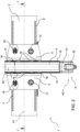
Figure 2 is a front view of the machine tool ofFigure 1 ; -
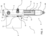
Figure 3 is a side elevation view of the machine tool ofFigure 1 ; -
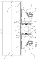
Figure 4 is a top view of the machine tool ofFigure 1 ; -
Figure 5 is a sectional view of the machine tool ofFigure 1 along section lines V-V; -
Figure 6 is a sectional view of the machine tool ofFigure 1 along section lines VI-VI; and -
Figure 7 is a partially sectional, plan view of a further variant of the machine tool ofFigure 1 . - With reference to
Figures 1 and2 ,number 1 indicates, as a whole, a machine tool, in particular a milling machine, preferably a CNC milling machine. Themilling machine 1 comprises a substantiallystraight guide element 2 extending along an axis A1, for example a horizontal one; twocarriages guide element 2 and are capable of sliding together along theguide element 2; aslide 5, which is interposed between thecarriages carriages carriages milling head 6, which is carried by theslide 5 and is configured to carry a milling tool (which is not shown in the accompanying Figures). - The
guide element 2 is supported by a fixed or movable support structure, which is not shown in the accompanying figures because it is not part of the invention. In particular, said support structure can assume different configurations. By way of example, the support structure comprises two vertical supports, each fixed to a respective end of theguide element 2, so as to define agantry milling machine 1. - With reference to
Figures 1-3 , theguide element 2 comprises arail 7 and arail 8, each extending in a direction that is substantially parallel to the axis A1. In particular, therails - According to a variant of the invention, which is not shown in the accompanying Figures, the
guide element 2 can comprise only one rail extending in a direction parallel to the axis A1. The number of rails of theguide element 2 can change and is not limited by the invention. - With reference to
Figures 3 and5 , theguide element 2 comprises arack 9 extending in a direction that is parallel to the axis A1 and, hence, parallel to therails - With reference to
Figures 3 ,4 and6 , each one of thecarriages runners 10, two of them being configured to slide on therail 7 and the other two being configured to slide on therail 8. In particular, eachrunner 10 is shaped so as to be coupled to the dovetail-shaped section of therails carriages rails carriages guide element 2 in all other directions. - According to a variant of the invention, which is not shown in the accompanying Figures, each
carriage runners 10, one of them being configured to slide on therail 7 and the other one being configured to slide on therail 8. The number ofrunners 10 of the twocarriages - With reference to
Figures 1-5 , thecarriage 3 comprises anelectric motor 11 and thecarriage 4 comprises anelectric motor 12. Eachelectric motor Figures 3 and5 ), which meshes with the rack 9 (Figures 3 and5 ). - In particular, the
motors Figures 3 and5 ) so as to limit the clearances of the coupling between the toothed wheels 13 (Figures 3 and5 ) and the rack 9 (Figures 3 and5 ). - With reference to
Figures 1-7 , theslide 5 is oblong in the direction A2, has a substantially rectangular section and comprises at least tworails respective carriage rails - Each
carriage slider 16, which is configured to slide along therespective rail slider 16 is shaped so as to be coupled to the dovetail-shaped section of therails slide 5 to slide along the axis A2 and avoid the relative movement of theslide 5 relative to thecarriages - In the specific case described and shown herein, the
slide 5 comprises tworails 14 and tworails 15. Thecarriage 3 comprises eightsliders 16, four of them being configured to slide on one of the tworails 14 and four of them being configured to slide on the other one of the tworails 14. Thecarriage 4 comprises eightsliders 16, four of them being configured to slide on one of the tworails 15 and four of them being configured to slide on the other one of the tworails 15. The number ofrails sliders 16 can change and is not limited by the invention. - With reference to
Figure 4 , theslide 5 comprises tworacks 17, each extending in a direction that is parallel to the axis A2 and, hence, parallel to therails - Furthermore, the
carriage 3 comprises anelectric motor 18 and thecarriage 4 comprises anelectric motor 19. Eachelectric motor toothed wheel 20, which meshes with therespective rack 17. - In particular, the
motors toothed wheels 20 so as to limit the clearances of the coupling between thetoothed wheels 20 and therack 17. - According to a variant of the invention, which is not shown in accompanying Figures, the
sole carriage 3 comprises a motor. - With reference to
Figures 1-3 , the millinghead 6 comprises twobodies body 22 and is not shown in the accompanying Figures. - In particular, the
body 21 is connected to theslide 5 so as to rotate relative to theslide 5 around the axis A2 and thebody 22 is connected to thebody 21 so as to slide relative to thebody 21 around an axis A3 that is perpendicular to the axis A2. - Furthermore, the milling
head 6 comprises motors and/or actuators, which are not shown in the accompanying Figures and are configured to move thebodies - In
Figures 1-7 , the axis A1 of theguide element 2 is horizontal and the axis A2 is vertical; according to a variant of the invention, which is not shown in the accompanying Figures, the axis A1 could be vertical and the axis A2 could be horizontal. - In use and with reference to
Figures 1-4 , themotors carriages guide element 2. In particular, in order to start the sliding of thecarriages motors motors motors carriages motors - In particular, the
motors
the torques exerted upon the respectivetoothed wheels 13 so as to modulate the stiffness of the connection between thecarriages slide 5 depending on the forces involved. - Similarly, the
motors slide 5 relative to thecarriages - The
bodies -
Figures 7 shows a variant in which theslide 5 has a tapered section, instead of a substantially rectangular one; therefore, the tworails 14 and the tworails 15 on the opposite sides of theslide 5 are not coplanar to one another, but are staggered in a direction parallel to the axis A1. Thecarriages slide 5, and thesliders 16 of eachcarriage corresponding rails - Finally, the invention can evidently be subjected to further variants to the embodiments described herein, though without going beyond the scope of protection set forth in the appended claims.
- For example, the motors controlling the movement of the
carriages slide 5 along the axis A2 could be hydraulic or pneumatic motors.
Claims (7)
- Machine tool comprising:- a substantially straight guide element (2) extending along a first axis (A1) and comprising a first rack (9) extending in a direction parallel to the first axis (A1);- two carriages (3, 4) arranged at a fixed distance (D) with respect to each other along the guide element (2) and slidable together along the guide element (2), at least one of the two carriages (3, 4) comprising at least one motor (11; 12) fitted with a toothed wheel (13) which engages with the first rack (9); and- a slide (5) interposed between the two carriages (3, 4), carried by the two carriages (3, 4) and slidable in relation to the two carriages (3, 4) along a second axis (A2) perpendicular to the first axis (A1);wherein said carriages (3, 4) are independent and mechanically linked together solely by said slide (5);wherein one of the two carriages (3, 4) comprises a first motor (11) and the other of the two carriages (3, 4) comprises a second motor (12), the first and second motors (11, 12) being fitted with respective toothed wheels (13) which mesh with the first rack (9) and are configured to exert respective torques in opposite directions upon the respective toothed wheels (13); andwherein the first and the second motor (11, 12) are configured to control, in a coordinated manner, the torques exerted upon the respective toothed wheels (13) so as to modulate the stiffness of the connection between the carriages (3, 4) and the slide (5) in a direction substantially parallel to the first axis (A1).
- Machine tool as claimed in claim 1, comprising a machining head (6) carried by the slide (5) and configured to carry a machining tool.
- Machine tool as claimed in one of the above claims, where the guide element (2) comprises at least one rail (7; 8) extending in a direction parallel to the first axis (A1), and each of the carriages (3, 4) comprises at least one runner (10) coupled to the rail (7, 8) slidably along the direction of the first axis (A1) and rigidly in a direction perpendicular to the first axis (A1).
- Machine tool as claimed in any of the above claims, wherein the slide (5) comprises at least two rails (14, 15), each of which is facing the respective carriage (3; 4) and extends in a direction parallel to the second axis (A2); each carriage (3; 4) being fitted with at least one slider (16) coupled to the respective rail (14, 15) in a sliding way along the direction of the second axis (A2) and substantially rigid in a direction perpendicular to the second axis (A2).
- Machine tool as claimed in any of the above claims, wherein the slide (5) comprises a second rack (17) extending in the direction parallel to the second axis (A2); at least one of the two carriages (3; 4) comprising at least one motor (18; 19) fitted with a toothed wheel (20) which engages with the second rack (17).
- Machine tool as claimed in claim 5, wherein one of the two carriages (3; 4) comprises a third motor (18) and a fourth motor (19), which are fitted with their respective toothed wheels (20) which engage with the second rack (17) and are configured to exert their respective torques in opposite direction upon the respective toothed wheels (20).
- Machine tool as claimed in claim 5, wherein one of the two carriages (3, 4) comprises a third motor (18) and the other of the two carriages (3, 4) comprises a fourth motor (19), said third and fourth motors (18, 19) being fitted with respective toothed wheels (20) which mesh with the second rack (17) and are designed to exert respective torques in opposite directions upon the respective toothed wheels (20).
Applications Claiming Priority (2)
| Application Number | Priority Date | Filing Date | Title |
|---|---|---|---|
| IT202000019342 | 2020-08-05 | ||
| PCT/IB2021/057200 WO2022029678A1 (en) | 2020-08-05 | 2021-08-05 | Machine tool with two independent carriages |
Publications (2)
| Publication Number | Publication Date |
|---|---|
| EP4192646A1 EP4192646A1 (en) | 2023-06-14 |
| EP4192646B1 true EP4192646B1 (en) | 2025-04-30 |
Family
ID=72886022
Family Applications (1)
| Application Number | Title | Priority Date | Filing Date |
|---|---|---|---|
| EP21765706.3A Active EP4192646B1 (en) | 2020-08-05 | 2021-08-05 | Machine tool with two independent carriages |
Country Status (5)
| Country | Link |
|---|---|
| US (1) | US20230294225A1 (en) |
| EP (1) | EP4192646B1 (en) |
| CN (1) | CN116745065A (en) |
| ES (1) | ES3032944T3 (en) |
| WO (1) | WO2022029678A1 (en) |
Families Citing this family (1)
| Publication number | Priority date | Publication date | Assignee | Title |
|---|---|---|---|---|
| IT202200013180A1 (en) * | 2022-06-22 | 2023-12-22 | Fidia Spa | MACHINE TOOL WITH INNOVATIVE CARRIAGE GEOMETRY |
Citations (3)
| Publication number | Priority date | Publication date | Assignee | Title |
|---|---|---|---|---|
| DE19645324A1 (en) * | 1996-11-04 | 1998-05-14 | Doerries Scharmann Gmbh | Machine tool for machining large components |
| EP1362664A2 (en) * | 2002-05-16 | 2003-11-19 | Soraluce, S. Coop | High speed milling machine |
| EP1750899B1 (en) * | 2004-04-07 | 2008-02-27 | Hpt Sinergy S.R.L. | Horizontal milling-boring machine with mobile column |
Family Cites Families (11)
| Publication number | Priority date | Publication date | Assignee | Title |
|---|---|---|---|---|
| US2902875A (en) * | 1957-01-07 | 1959-09-08 | Detroit Broach & Machine Compa | Means for reciprocating elements of machine tools and the like |
| US4550626A (en) * | 1983-03-14 | 1985-11-05 | Frans Brouwer | Servo-motor assembly for machine slides |
| JPH10228317A (en) * | 1997-02-14 | 1998-08-25 | Namu:Kk | Positioning device |
| DE10032552A1 (en) * | 2000-06-29 | 2002-01-17 | Werkzeugmaschinenfabrik Und Gi | Guide system for a coordinate carriage of a machine tool |
| DE602007006034D1 (en) * | 2006-09-21 | 2010-06-02 | Airbus Operations Sas | DEVICE FOR OVERHEAD MACHINING OF FIXED ELEMENTS |
| DE102008034728B4 (en) * | 2008-07-25 | 2014-02-13 | Deckel Maho Seebach Gmbh | Carrying device for workpieces or tools of a machine tool |
| DE102009013356A1 (en) * | 2009-03-16 | 2010-09-23 | P + L Gmbh & Co. Kg | Machine tool guide block assembly |
| CN103567461A (en) * | 2012-07-20 | 2014-02-12 | 鸿准精密模具(昆山)有限公司 | Turning device |
| CN103567465B (en) * | 2012-07-20 | 2019-10-29 | 鸿准精密模具(昆山)有限公司 | Turning equipment |
| CN102990479B (en) * | 2012-12-10 | 2015-01-14 | 山东大学 | High-speed and high-efficiency machining center for large aluminum members |
| CN108526914B (en) * | 2018-03-20 | 2020-05-15 | 诺伯特智能装备(山东)有限公司 | Movable cross beam locking device of five-axis gantry machine |
-
2021
- 2021-08-05 ES ES21765706T patent/ES3032944T3/en active Active
- 2021-08-05 US US18/019,588 patent/US20230294225A1/en active Pending
- 2021-08-05 EP EP21765706.3A patent/EP4192646B1/en active Active
- 2021-08-05 WO PCT/IB2021/057200 patent/WO2022029678A1/en not_active Ceased
- 2021-08-05 CN CN202180062905.XA patent/CN116745065A/en active Pending
Patent Citations (3)
| Publication number | Priority date | Publication date | Assignee | Title |
|---|---|---|---|---|
| DE19645324A1 (en) * | 1996-11-04 | 1998-05-14 | Doerries Scharmann Gmbh | Machine tool for machining large components |
| EP1362664A2 (en) * | 2002-05-16 | 2003-11-19 | Soraluce, S. Coop | High speed milling machine |
| EP1750899B1 (en) * | 2004-04-07 | 2008-02-27 | Hpt Sinergy S.R.L. | Horizontal milling-boring machine with mobile column |
Also Published As
| Publication number | Publication date |
|---|---|
| ES3032944T3 (en) | 2025-07-29 |
| EP4192646A1 (en) | 2023-06-14 |
| WO2022029678A1 (en) | 2022-02-10 |
| CN116745065A (en) | 2023-09-12 |
| US20230294225A1 (en) | 2023-09-21 |
Similar Documents
| Publication | Publication Date | Title |
|---|---|---|
| JP6227184B1 (en) | Flexible multiple table device | |
| EP0583085B1 (en) | Positioning apparatus for multiple-spindle machining | |
| CN102821911B (en) | Modular multifunctional machine tools for comprehensive machining processes | |
| RU2562189C2 (en) | Method and device for machining of oblong rotary-asymmetric blanks shaped to turbine blades | |
| JP5030606B2 (en) | Machining center | |
| US6449848B1 (en) | Flexible fixture method | |
| KR101430047B1 (en) | Saddle for gantry roader and the gantry roader using the same | |
| DE69901301T2 (en) | KINEMATIC PARALLEL STRUCTURE OF A MACHINE TOOL | |
| EP3616832A1 (en) | Machine tool, in particular lathe | |
| JP5389213B2 (en) | Machining center | |
| CN102699685A (en) | Numerical control gantry milling machine of fixed beam | |
| US8182313B2 (en) | Carriage arrangement for a machine tool | |
| KR102818369B1 (en) | Machine tool and method for machining a rotary part having a grooved profile by a forming method | |
| DE102016115447A1 (en) | machine tool | |
| CN110774015B (en) | Series-parallel machine tool with overconstrained few-degree-of-freedom parallel modules and movement method | |
| EP2412475B1 (en) | Compensation system for a machine tool | |
| US20230294225A1 (en) | Machine tool with two independent carriages | |
| EP1166953B1 (en) | Machine tool with Guiding system for a body with motion in three orthogonal directions | |
| KR101713439B1 (en) | Machining center for multi-spindle | |
| US7721410B2 (en) | Machine tool comprising a clamping device on both sides | |
| CN202701766U (en) | Fixation-girder numerical control gantry milling machine | |
| JP2025524225A (en) | machine tools | |
| EP2371502A1 (en) | Multifunctional machining head | |
| EP2944419A1 (en) | Machining center with separable workpiece supporting table | |
| EP4341038B1 (en) | Machine tool for machining semi-finished aluminum or titanium alloy products |
Legal Events
| Date | Code | Title | Description |
|---|---|---|---|
| STAA | Information on the status of an ep patent application or granted ep patent |
Free format text: STATUS: UNKNOWN |
|
| STAA | Information on the status of an ep patent application or granted ep patent |
Free format text: STATUS: THE INTERNATIONAL PUBLICATION HAS BEEN MADE |
|
| PUAI | Public reference made under article 153(3) epc to a published international application that has entered the european phase |
Free format text: ORIGINAL CODE: 0009012 |
|
| STAA | Information on the status of an ep patent application or granted ep patent |
Free format text: STATUS: REQUEST FOR EXAMINATION WAS MADE |
|
| 17P | Request for examination filed |
Effective date: 20230224 |
|
| AK | Designated contracting states |
Kind code of ref document: A1 Designated state(s): AL AT BE BG CH CY CZ DE DK EE ES FI FR GB GR HR HU IE IS IT LI LT LU LV MC MK MT NL NO PL PT RO RS SE SI SK SM TR |
|
| DAV | Request for validation of the european patent (deleted) | ||
| DAX | Request for extension of the european patent (deleted) | ||
| GRAP | Despatch of communication of intention to grant a patent |
Free format text: ORIGINAL CODE: EPIDOSNIGR1 |
|
| STAA | Information on the status of an ep patent application or granted ep patent |
Free format text: STATUS: GRANT OF PATENT IS INTENDED |
|
| INTG | Intention to grant announced |
Effective date: 20241108 |
|
| GRAS | Grant fee paid |
Free format text: ORIGINAL CODE: EPIDOSNIGR3 |
|
| GRAA | (expected) grant |
Free format text: ORIGINAL CODE: 0009210 |
|
| STAA | Information on the status of an ep patent application or granted ep patent |
Free format text: STATUS: THE PATENT HAS BEEN GRANTED |
|
| AK | Designated contracting states |
Kind code of ref document: B1 Designated state(s): AL AT BE BG CH CY CZ DE DK EE ES FI FR GB GR HR HU IE IS IT LI LT LU LV MC MK MT NL NO PL PT RO RS SE SI SK SM TR |
|
| REG | Reference to a national code |
Ref country code: CH Ref legal event code: EP Ref country code: GB Ref legal event code: FG4D |
|
| REG | Reference to a national code |
Ref country code: DE Ref legal event code: R096 Ref document number: 602021030061 Country of ref document: DE |
|
| REG | Reference to a national code |
Ref country code: IE Ref legal event code: FG4D |
|
| REG | Reference to a national code |
Ref country code: ES Ref legal event code: FG2A Ref document number: 3032944 Country of ref document: ES Kind code of ref document: T3 Effective date: 20250729 |
|
| REG | Reference to a national code |
Ref country code: AT Ref legal event code: MK05 Ref document number: 1789607 Country of ref document: AT Kind code of ref document: T Effective date: 20250430 |
|
| PG25 | Lapsed in a contracting state [announced via postgrant information from national office to epo] |
Ref country code: FI Free format text: LAPSE BECAUSE OF FAILURE TO SUBMIT A TRANSLATION OF THE DESCRIPTION OR TO PAY THE FEE WITHIN THE PRESCRIBED TIME-LIMIT Effective date: 20250430 Ref country code: PT Free format text: LAPSE BECAUSE OF FAILURE TO SUBMIT A TRANSLATION OF THE DESCRIPTION OR TO PAY THE FEE WITHIN THE PRESCRIBED TIME-LIMIT Effective date: 20250901 |
|
| PGFP | Annual fee paid to national office [announced via postgrant information from national office to epo] |
Ref country code: ES Payment date: 20250916 Year of fee payment: 5 |
|
| PGFP | Annual fee paid to national office [announced via postgrant information from national office to epo] |
Ref country code: DE Payment date: 20250827 Year of fee payment: 5 |
|
| REG | Reference to a national code |
Ref country code: LT Ref legal event code: MG9D |
|
| PG25 | Lapsed in a contracting state [announced via postgrant information from national office to epo] |
Ref country code: GR Free format text: LAPSE BECAUSE OF FAILURE TO SUBMIT A TRANSLATION OF THE DESCRIPTION OR TO PAY THE FEE WITHIN THE PRESCRIBED TIME-LIMIT Effective date: 20250731 Ref country code: NO Free format text: LAPSE BECAUSE OF FAILURE TO SUBMIT A TRANSLATION OF THE DESCRIPTION OR TO PAY THE FEE WITHIN THE PRESCRIBED TIME-LIMIT Effective date: 20250730 |
|
| PG25 | Lapsed in a contracting state [announced via postgrant information from national office to epo] |
Ref country code: PL Free format text: LAPSE BECAUSE OF FAILURE TO SUBMIT A TRANSLATION OF THE DESCRIPTION OR TO PAY THE FEE WITHIN THE PRESCRIBED TIME-LIMIT Effective date: 20250430 Ref country code: NL Free format text: LAPSE BECAUSE OF FAILURE TO SUBMIT A TRANSLATION OF THE DESCRIPTION OR TO PAY THE FEE WITHIN THE PRESCRIBED TIME-LIMIT Effective date: 20250430 |
|
| PGFP | Annual fee paid to national office [announced via postgrant information from national office to epo] |
Ref country code: IT Payment date: 20250714 Year of fee payment: 5 |
|
| PG25 | Lapsed in a contracting state [announced via postgrant information from national office to epo] |
Ref country code: BG Free format text: LAPSE BECAUSE OF FAILURE TO SUBMIT A TRANSLATION OF THE DESCRIPTION OR TO PAY THE FEE WITHIN THE PRESCRIBED TIME-LIMIT Effective date: 20250430 |
|
| PG25 | Lapsed in a contracting state [announced via postgrant information from national office to epo] |
Ref country code: HR Free format text: LAPSE BECAUSE OF FAILURE TO SUBMIT A TRANSLATION OF THE DESCRIPTION OR TO PAY THE FEE WITHIN THE PRESCRIBED TIME-LIMIT Effective date: 20250430 |
|
| PG25 | Lapsed in a contracting state [announced via postgrant information from national office to epo] |
Ref country code: AT Free format text: LAPSE BECAUSE OF FAILURE TO SUBMIT A TRANSLATION OF THE DESCRIPTION OR TO PAY THE FEE WITHIN THE PRESCRIBED TIME-LIMIT Effective date: 20250430 |
|
| PGFP | Annual fee paid to national office [announced via postgrant information from national office to epo] |
Ref country code: FR Payment date: 20250825 Year of fee payment: 5 |
|
| PG25 | Lapsed in a contracting state [announced via postgrant information from national office to epo] |
Ref country code: RS Free format text: LAPSE BECAUSE OF FAILURE TO SUBMIT A TRANSLATION OF THE DESCRIPTION OR TO PAY THE FEE WITHIN THE PRESCRIBED TIME-LIMIT Effective date: 20250731 |
|
| PG25 | Lapsed in a contracting state [announced via postgrant information from national office to epo] |
Ref country code: IS Free format text: LAPSE BECAUSE OF FAILURE TO SUBMIT A TRANSLATION OF THE DESCRIPTION OR TO PAY THE FEE WITHIN THE PRESCRIBED TIME-LIMIT Effective date: 20250830 |
|
| PG25 | Lapsed in a contracting state [announced via postgrant information from national office to epo] |
Ref country code: LV Free format text: LAPSE BECAUSE OF FAILURE TO SUBMIT A TRANSLATION OF THE DESCRIPTION OR TO PAY THE FEE WITHIN THE PRESCRIBED TIME-LIMIT Effective date: 20250430 |
|
| PG25 | Lapsed in a contracting state [announced via postgrant information from national office to epo] |
Ref country code: DK Free format text: LAPSE BECAUSE OF FAILURE TO SUBMIT A TRANSLATION OF THE DESCRIPTION OR TO PAY THE FEE WITHIN THE PRESCRIBED TIME-LIMIT Effective date: 20250430 Ref country code: SM Free format text: LAPSE BECAUSE OF FAILURE TO SUBMIT A TRANSLATION OF THE DESCRIPTION OR TO PAY THE FEE WITHIN THE PRESCRIBED TIME-LIMIT Effective date: 20250430 |
|
| PG25 | Lapsed in a contracting state [announced via postgrant information from national office to epo] |
Ref country code: CZ Free format text: LAPSE BECAUSE OF FAILURE TO SUBMIT A TRANSLATION OF THE DESCRIPTION OR TO PAY THE FEE WITHIN THE PRESCRIBED TIME-LIMIT Effective date: 20250430 |
|
| PG25 | Lapsed in a contracting state [announced via postgrant information from national office to epo] |
Ref country code: EE Free format text: LAPSE BECAUSE OF FAILURE TO SUBMIT A TRANSLATION OF THE DESCRIPTION OR TO PAY THE FEE WITHIN THE PRESCRIBED TIME-LIMIT Effective date: 20250430 |
|
| PG25 | Lapsed in a contracting state [announced via postgrant information from national office to epo] |
Ref country code: SK Free format text: LAPSE BECAUSE OF FAILURE TO SUBMIT A TRANSLATION OF THE DESCRIPTION OR TO PAY THE FEE WITHIN THE PRESCRIBED TIME-LIMIT Effective date: 20250430 |
|
| REG | Reference to a national code |
Ref country code: DE Ref legal event code: R097 Ref document number: 602021030061 Country of ref document: DE |
|
| PG25 | Lapsed in a contracting state [announced via postgrant information from national office to epo] |
Ref country code: RO Free format text: LAPSE BECAUSE OF FAILURE TO SUBMIT A TRANSLATION OF THE DESCRIPTION OR TO PAY THE FEE WITHIN THE PRESCRIBED TIME-LIMIT Effective date: 20250430 |
|
| PLBE | No opposition filed within time limit |
Free format text: ORIGINAL CODE: 0009261 |
|
| STAA | Information on the status of an ep patent application or granted ep patent |
Free format text: STATUS: NO OPPOSITION FILED WITHIN TIME LIMIT |
|
| REG | Reference to a national code |
Ref country code: CH Ref legal event code: L10 Free format text: ST27 STATUS EVENT CODE: U-0-0-L10-L00 (AS PROVIDED BY THE NATIONAL OFFICE) Effective date: 20260311 |
|
| REG | Reference to a national code |
Ref country code: CH Ref legal event code: H13 Free format text: ST27 STATUS EVENT CODE: U-0-0-H10-H13 (AS PROVIDED BY THE NATIONAL OFFICE) Effective date: 20260324 |
|
| PG25 | Lapsed in a contracting state [announced via postgrant information from national office to epo] |
Ref country code: MC Free format text: LAPSE BECAUSE OF FAILURE TO SUBMIT A TRANSLATION OF THE DESCRIPTION OR TO PAY THE FEE WITHIN THE PRESCRIBED TIME-LIMIT Effective date: 20250430 |
|
| 26N | No opposition filed |
Effective date: 20260202 |
|
| PG25 | Lapsed in a contracting state [announced via postgrant information from national office to epo] |
Ref country code: LU Free format text: LAPSE BECAUSE OF NON-PAYMENT OF DUE FEES Effective date: 20250805 |
|
| PG25 | Lapsed in a contracting state [announced via postgrant information from national office to epo] |
Ref country code: CH Free format text: LAPSE BECAUSE OF NON-PAYMENT OF DUE FEES Effective date: 20250831 |
|
| GBPC | Gb: european patent ceased through non-payment of renewal fee |
Effective date: 20250805 |